US8251863B2 - Continuously variable transmission with multiple outputs - Google Patents
Continuously variable transmission with multiple outputsDownload PDFInfo
- Publication number
- US8251863B2 US8251863B2US11/849,953US84995307AUS8251863B2US 8251863 B2US8251863 B2US 8251863B2US 84995307 AUS84995307 AUS 84995307AUS 8251863 B2US8251863 B2US 8251863B2
- Authority
- US
- United States
- Prior art keywords
- continuously variable
- input shaft
- variable transmission
- central input
- transmission units
- Prior art date
- Legal status (The legal status is an assumption and is not a legal conclusion. Google has not performed a legal analysis and makes no representation as to the accuracy of the status listed.)
- Expired - Fee Related, expires
Links
Images


Classifications
- F—MECHANICAL ENGINEERING; LIGHTING; HEATING; WEAPONS; BLASTING
- F16—ENGINEERING ELEMENTS AND UNITS; GENERAL MEASURES FOR PRODUCING AND MAINTAINING EFFECTIVE FUNCTIONING OF MACHINES OR INSTALLATIONS; THERMAL INSULATION IN GENERAL
- F16H—GEARING
- F16H15/00—Gearings for conveying rotary motion with variable gear ratio, or for reversing rotary motion, by friction between rotary members
- F16H15/02—Gearings for conveying rotary motion with variable gear ratio, or for reversing rotary motion, by friction between rotary members without members having orbital motion
- F16H15/04—Gearings providing a continuous range of gear ratios
- F16H15/40—Gearings providing a continuous range of gear ratios in which two members co-operative by means of balls, or rollers of uniform effective diameter, not mounted on shafts
- Y—GENERAL TAGGING OF NEW TECHNOLOGICAL DEVELOPMENTS; GENERAL TAGGING OF CROSS-SECTIONAL TECHNOLOGIES SPANNING OVER SEVERAL SECTIONS OF THE IPC; TECHNICAL SUBJECTS COVERED BY FORMER USPC CROSS-REFERENCE ART COLLECTIONS [XRACs] AND DIGESTS
- Y10—TECHNICAL SUBJECTS COVERED BY FORMER USPC
- Y10T—TECHNICAL SUBJECTS COVERED BY FORMER US CLASSIFICATION
- Y10T74/00—Machine element or mechanism
- Y10T74/20—Control lever and linkage systems
- Y10T74/20207—Multiple controlling elements for single controlled element
- Y10T74/20305—Robotic arm
Definitions
- Passive robots intended for collaboration with a human operatorwhich are sometimes called “cobots,” move in response to a force that a user manually applies to its end point.
- Limits or constraints placed on the end point positiondetermine the end point trajectory, while the energy to move the end point along the trajectory is supplied by the user. These limits collectively define “virtual surfaces” which separate a workspace into free regions, in which a user may freely move the end point of the cobot, and restricted regions, in which the user cannot freely move the end point.
- cobotsmay utilize motors, the motors are not used to move the end point along the trajectory.
- the joints of a cobotinclude nonholonomic elements.
- Revolute joints in cobotsare commonly formed using continuously variable transmissions as a nonholonomic element.
- a continuously variable transmission (CVT)is one that can vary its transmission ratio over a continuous, predefined range of values.
- a continuously variable transmission that can vary its transmission ratio over a continuous range of values including zero and including reversal (negative values)is sometimes referred to as an infinitely variable transmission.
- a transmission or actuatorincludes an input driving multiple outputs, each output having an independently and continuously variable transmission ratio.
- This transmissionpermits a single, powered actuator to be shared for driving multiple outputs, permitting more efficient utilization of power and savings of weight and space without sacrificing the ability to independently control each output with, for example, a computer.
- Such a transmissionis particularly useful and used to advantage in robotic systems, such as cobots, requiring the establishment of mechanically constrained velocity ratios among several degrees of freedom in a workspace, with the velocity ratios being continuously adjustable under computer control.
- the transmissionestablishes the necessary velocity ratios and allows them to be independently varied under computer control.
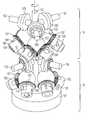
- FIG. 1illustrates certain components of a transmission having a single drive shaft coupled with a plurality of CVTs, with support structures omitted.
- FIG. 2illustrates certain components a single CVT from FIG. 1 . Support and other structures have been omitted in order to explain the kinematics of the CVT.
- FIG. 3illustrates the CVT of FIG. 2 , with the additional synchronization gears and bearings, and a cable pulley coupled with its output.
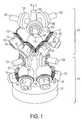
- FIG. 4is a perspective illustration of one layer of the transmission of FIG. 1 with support structures shown.
- FIG. 5is a perspective illustration of the transmission of FIG. 1 with support structures shown.
- a plurality of continuously variable transmission unitsare arrayed circumferentially around a common rotating shaft.
- the shaftis connected to a source of input rotational motion, for example an electric motor. Additional arrays can be distributed along the length of the common shaft.
- Each CVTenables rapid, accurate and independent adjustment of the transmission ratio of each output by means of a computer.
- the transmissionthus easily permits relating output speeds one to another under computer control, making possible the establishment of virtual surfaces and other haptic effects in a multidimensional workspace to which the transmission outputs are kinematically linked.
- An example of such a workspaceis that of a robotic or prosthetic hand.
- each CVTfurther enables extending the range of capabilities of the input motor beyond the range of speed and torque otherwise available with a fixed ratio transmission, which is desirable for many applications.
- a CVT unitis comprised of a sphere which conveys motion from the common rotating shaft to an output roller, with the axis of rotation of the output roller orthogonal to the axis of rotation of the common rotating shaft.
- the axis of rotation of the spheredetermines the transmission ratio from the common rotating shaft to output roller.
- the sphere's axis of rotationis determined by the axes of rotation of two steering rollers that also contact the sphere. These rollers are preferably passive (non-driven). Steering the rollers changes the transmission ratio from common rotating shaft to the output roller. Four points of contact of the sphere with the two shafts and two rollers are sufficient, in this example, to fully constrain the sphere except for rotation.
- the common rotating shaft, sphere, output roller, and steering rollersare preferably made of hard materials. In a preferred embodiment they are made of steel. Surface coatings may be used to enhance the hardness of the surface, its wear resistance, and rolling traction. Ceramic materials or coatings may also be used for these purposes. Traction fluids may also be used to increase rolling traction.
- each CVTalso independently possesses the ability to adjust its backdrivability, or impedance as seen at the output, varying from completely locked to completely free.
- Eachmay be independently locked by setting their speed to zero with minimal dissipation of heat.
- jointscan be clutched under heavy loads, or unlocked under power failure, without the presence of additional clutch or brake actuators.
- the transmissionpermits a wide range of mechanical impedances to be rendered to n degrees of freedom, using n+1 actuators and n continuously variable transmissions.
- such transmissionstend to exhibit low reflected inertia, as ascertained from an actuated joint connected to one of its outputs, and, due to the absence of gear teeth, to operate with little vibration and sound.
- common rotating shaft 102may be driven by a rotational actuator 101 , such as an electric motor, preferably a DC brushless servomotor.
- a rotational actuator 101such as an electric motor, preferably a DC brushless servomotor.
- common rotating shaft 102is not driven by a rotational actuator.
- the angular orientation of common rotating shaft 102is measured by an orientation measuring device, for example an optical encoder. This device is not illustrated. Use of such devices for this purpose is well known.
- the angular velocity of common rotating shaft 102may also be measured. The angular velocity can be measured or determined in any of a variety of well known ways. In a preferred embodiment the angular position is measured by an encoder, and the angular velocity is derived from the angular position by numerical differentiation.
- Common rotating shaft 102is rotatably supported in a stationary support structure, such as a body of the transmission, by bearings. Neither the body nor the bearings are shown in FIG. 1 .
- Common rotating shaft 102contacts a plurality of spheres 103 .
- the spheresare in rolling contact with the shaft, such that rotation of the shaft causes rotation of each sphere 103 about its center.
- At least two, and preferably three or more, of the plurality spheres 103are arrayed preferably symmetrically around the axis of the shaft in a layer 110 .
- the centers of the spheres in a single layerpreferably lie within a common plane. Additional layers may be disposed along common rotating shaft 102 . In the example shown in FIG. 1 , there are two layers each containing three spheres 103 .
- Each sphere 103is also in rolling contact with two steering rollers 104 , such that the orientations of the axes of rotation of the two steering rollers 104 constrain the orientation of the axis of rotation of sphere 103 that the two steering rollers contact. These rollers are preferably not driven, and thus completely passive.
- Each steering roller 104is rotatably attached to an axle 105 within a steering cup 106 .
- Steering cup 106is rotatably attached to the body (not shown in FIG. 1 ) of the transmission by bearings, such that the contact point between steering roller 104 and sphere 103 is stationary as steering cup 106 rotates.
- Each pair of steering cups 106 contacting a single sphere 103are synchronized in their orientations by a synchronization mechanism, which may be mechanical or electromechanical.
- a pair synchronization gears 107each coupled with a respective steering cup, mesh with each other.
- the two synchronization gears 107are 45 degree bevel gears.
- the steering of the two rollers contacting one sphereis driven by one or two motors. These motors are preferably under computer control. (The computer is not shown in the figures.) In a preferred embodiment the steering angles of the two rollers are synchronized by gears and thus only one motor is needed.
- Each sphere 103is also in rolling contact with output roller 108 , such that rotation of sphere 103 causes rotation of output roller 108 .
- Output roller 108is rotatably supported to the body of the transmission (not shown in FIG. 1 ) by bearings.
- Each sphere 103 , pair of contacting steering rollers 104 , and contacting output roller 108comprises an example of a preferred form of continuously variable transmission (CVT), having a transmission ratio between the common rotating shaft 102 and the output roller 108 determined by the steering angles of the steering rollers 104 .
- CVTcontinuously variable transmission
- FIG. 2which illustrates a single CVT as shown in FIG. 1 , the rotational axis of each component is shown as a dashed line.
- the axis 208 of output roller 108is perpendicular to the axis 202 of common rotating shaft 102 .
- the axes 206 of the two steering cups 106intersect at the center of sphere 103 , and preferably are perpendicular to one another.
- the axis of each steering cup 106differs from the axis of common rotating shaft 102 by 45 degrees, and is skew to it.
- Each sphere 103is also in rolling contact with output roller 108 affixed to shaft 109 , such that rotation of sphere 103 causes rotation of output roller 108 and shaft 109 .
- Shaft 109is rotatably attached to the body (not shown) of the transmission or other support structure by bearings.
- Synchronization gears 107cause steering cups 106 to turn in opposite direction, such that steering rollers 104 within steering cups 106 properly determine the axis of rotation of sphere 103 .
- An actuator 312may drive the orientation of steering cup 106 .
- the actuatormay be an ultrasonic motor, the rotor of which is shown in FIG. 3 as rotor 306 .
- synchronizationcould be accomplished by separately actuating the two steering cups 106 .
- a sensor 313is preferred for reading the angle of at least one steering cup 106 for each CVT, and for providing feedback to a control computer or motor controller in order to accurately control the angle and angular velocity of steering cup 106 .
- the sensormay be any of the many known types of rotational sensor.
- One preferred exampleis a sensor comprising a magnet mounted to the steering cup and a pair of analog Hall sensors, which give output voltages proportional to the sine and cosine of the angle of the magnet, and thus of steering cup 106 .
- a sensormight not be needed, for instance if rotor 306 is part of a stepper motor.
- Output roller 108produces a rotational output.
- the rotational outputpulls a cable, which may communicate to, for example, a joint of a prosthetic or robotic hand.
- the rotational outputis increased in torque and decreased in speed by a gear reduction 308 which drives a pulley 309 , upon which said cable is wrapped.
- bearings 307support steering cups 106 and synchronization gears 107 .
- Bearing 310supports output roller 108 .
- Bearings 311support pulley 309 .
- an example of support structure for each layer of CVTs 110is a body formed of two disk-shaped structures, referred to herein as “disks.”
- an upper disk 405 and a lower disk 406are held together by bolts 404 with belleville washers 403 , such that belleville washers 403 serve to maintain a tension for pulling disks 405 and 406 together.
- belleville washers 403serve to maintain a tension for pulling disks 405 and 406 together.
- One advantage of this structureis that pulling the two disks together preloads all the frictional rolling contacts—the steering rollers and output roller against the sphere—in each of the several CVTs in the layer.
- other or additional methods and structures of preloadingcan be substituted or used.
- Each slots 401gives access for a cable wound around a pulley 309 .
- Stator 402 of a motor which drives steering cup 106may be seen in this figure, for a preferred embodiment in which one ultrasonic motor drives one of each pair of steering cups 106 .
- the foregoing transmissionis particularly useful for, and used advantageously in, cobots requiring the establishment of mechanically constrained velocity ratios among several degrees of freedom in a workspace control.
- the ratioscan, preferably, be made continuously variable between positive and negative values, including zero, and may be varied by electromechanical actuators under computer control.
- the transmissionrelates the output speeds one to another under computer control, and thus makes possible the establishment of virtual surfaces and other haptic effects in a multidimensional workspace to which the transmission outputs are kinematically linked.
- One exemplary application of the transmissionis for prosthetic or robotic limbs, such as arms and fingers.
- the transmission or actuatorcan be made small enough to fit inside of, for example, a prosthetic or robotic wrist.
Landscapes
- Engineering & Computer Science (AREA)
- General Engineering & Computer Science (AREA)
- Mechanical Engineering (AREA)
- Manipulator (AREA)
Abstract
Description
Claims (19)
Priority Applications (1)
| Application Number | Priority Date | Filing Date | Title |
|---|---|---|---|
| US11/849,953US8251863B2 (en) | 2006-09-01 | 2007-09-04 | Continuously variable transmission with multiple outputs |
Applications Claiming Priority (2)
| Application Number | Priority Date | Filing Date | Title |
|---|---|---|---|
| US84171006P | 2006-09-01 | 2006-09-01 | |
| US11/849,953US8251863B2 (en) | 2006-09-01 | 2007-09-04 | Continuously variable transmission with multiple outputs |
Publications (2)
| Publication Number | Publication Date |
|---|---|
| US20080081728A1 US20080081728A1 (en) | 2008-04-03 |
| US8251863B2true US8251863B2 (en) | 2012-08-28 |
Family
ID=39261766
Family Applications (1)
| Application Number | Title | Priority Date | Filing Date |
|---|---|---|---|
| US11/849,953Expired - Fee RelatedUS8251863B2 (en) | 2006-09-01 | 2007-09-04 | Continuously variable transmission with multiple outputs |
Country Status (1)
| Country | Link |
|---|---|
| US (1) | US8251863B2 (en) |
Cited By (9)
| Publication number | Priority date | Publication date | Assignee | Title |
|---|---|---|---|---|
| US20120067166A1 (en)* | 2009-06-08 | 2012-03-22 | Tangent Robotics Llc | Spherical gear |
| US9366323B1 (en) | 2014-05-28 | 2016-06-14 | Google Inc. | Variable transmission system |
| US9914003B2 (en) | 2013-03-05 | 2018-03-13 | Alterg, Inc. | Monocolumn unweighting systems |
| US10265565B2 (en) | 2013-03-14 | 2019-04-23 | Alterg, Inc. | Support frame and related unweighting system |
| US10342461B2 (en) | 2007-10-15 | 2019-07-09 | Alterg, Inc. | Method of gait evaluation and training with differential pressure system |
| US10493309B2 (en) | 2013-03-14 | 2019-12-03 | Alterg, Inc. | Cantilevered unweighting systems |
| US10859142B2 (en) | 2017-11-02 | 2020-12-08 | Stephen Douglas Williams | Slip-modulated proprioceptive infinitely variable transmission and robotic power distribution system |
| US11806564B2 (en) | 2013-03-14 | 2023-11-07 | Alterg, Inc. | Method of gait evaluation and training with differential pressure system |
| US11957954B2 (en) | 2017-10-18 | 2024-04-16 | Alterg, Inc. | Gait data collection and analytics system and methods for operating unweighting training systems |
Families Citing this family (40)
| Publication number | Priority date | Publication date | Assignee | Title |
|---|---|---|---|---|
| US7011600B2 (en) | 2003-02-28 | 2006-03-14 | Fallbrook Technologies Inc. | Continuously variable transmission |
| AU2005294611B2 (en) | 2004-10-05 | 2011-10-06 | Enviolo B.V. | Continuously variable transmission |
| KR101831822B1 (en) | 2005-10-28 | 2018-02-23 | 폴브룩 인텔렉츄얼 프로퍼티 컴퍼니 엘엘씨 | Electromotive drives |
| ES2424652T3 (en) | 2005-11-22 | 2013-10-07 | Fallbrook Intellectual Property Company Llc | Continuously variable transmission |
| EP1963713B1 (en) | 2005-12-09 | 2015-02-25 | Fallbrook Intellectual Property Company LLC | Continuously variable transmission |
| EP1811202A1 (en)* | 2005-12-30 | 2007-07-25 | Fallbrook Technologies, Inc. | A continuously variable gear transmission |
| US7882762B2 (en) | 2006-01-30 | 2011-02-08 | Fallbrook Technologies Inc. | System for manipulating a continuously variable transmission |
| CN102278200B (en)* | 2006-06-26 | 2014-05-14 | 福博科知识产权有限责任公司 | Continuously variable transmission |
| US8376903B2 (en) | 2006-11-08 | 2013-02-19 | Fallbrook Intellectual Property Company Llc | Clamping force generator |
| US8738255B2 (en)* | 2007-02-01 | 2014-05-27 | Fallbrook Intellectual Property Company Llc | Systems and methods for control of transmission and/or prime mover |
| CN104121345B (en) | 2007-02-12 | 2017-01-11 | 福博科知识产权有限责任公司 | Continuously variable transmission and method therefor |
| EP2122198B1 (en) | 2007-02-16 | 2014-04-16 | Fallbrook Intellectual Property Company LLC | Method and assembly |
| EP2573424A3 (en) | 2007-04-24 | 2017-07-26 | Fallbrook Intellectual Property Company LLC | Electric traction drives |
| US8641577B2 (en) | 2007-06-11 | 2014-02-04 | Fallbrook Intellectual Property Company Llc | Continuously variable transmission |
| CA2983530A1 (en) | 2007-07-05 | 2009-01-08 | Fallbrook Intellectual Property Company, Llc | Continuously variable transmission |
| WO2009065055A2 (en) | 2007-11-16 | 2009-05-22 | Fallbrook Technologies Inc. | Controller for variable transmission |
| CN105197177B (en) | 2007-12-21 | 2019-05-07 | 福博科知识产权有限责任公司 | Automatic transmission and method for it |
| CA2716908C (en) | 2008-02-29 | 2017-06-27 | Fallbrook Technologies Inc. | Continuously and/or infinitely variable transmissions and methods therefor |
| US8317651B2 (en) | 2008-05-07 | 2012-11-27 | Fallbrook Intellectual Property Company Llc | Assemblies and methods for clamping force generation |
| CN102112778B (en) | 2008-06-06 | 2013-10-16 | 福博科技术公司 | Infinitely variable transmission, continuously variable transmission, methods, assemblies, subassemblies and components therefor |
| EP3270006B1 (en) | 2008-06-23 | 2020-12-30 | Fallbrook Intellectual Property Company LLC | Continuously variable transmission |
| US8818661B2 (en) | 2008-08-05 | 2014-08-26 | Fallbrook Intellectual Property Company Llc | Methods for control of transmission and prime mover |
| US8469856B2 (en) | 2008-08-26 | 2013-06-25 | Fallbrook Intellectual Property Company Llc | Continuously variable transmission |
| US8167759B2 (en) | 2008-10-14 | 2012-05-01 | Fallbrook Technologies Inc. | Continuously variable transmission |
| EP2419658B1 (en) | 2009-04-16 | 2013-10-02 | Fallbrook Intellectual Property Company LLC | Stator assembly and shifting mechanism for a continuously variable transmission |
| CA2783542C (en) | 2009-12-14 | 2015-10-13 | Hdt Robotics, Inc. | One motor finger mechanism |
| US8512195B2 (en) | 2010-03-03 | 2013-08-20 | Fallbrook Intellectual Property Company Llc | Infinitely variable transmissions, continuously variable transmissions, methods, assemblies, subassemblies, and components therefor |
| US8888643B2 (en) | 2010-11-10 | 2014-11-18 | Fallbrook Intellectual Property Company Llc | Continuously variable transmission |
| AU2012240435B2 (en) | 2011-04-04 | 2016-04-28 | Fallbrook Intellectual Property Company Llc | Auxiliary power unit having a continuously variable transmission |
| EP2769122A4 (en) | 2011-10-20 | 2017-07-05 | Paul D. Okulov | Infinitely variable traction drive employing alternate steerable rollers |
| MX350737B (en) | 2012-01-23 | 2017-09-15 | Fallbrook Ip Co Llc | Infinitely variable transmissions, continuously variable transmissions methods, assemblies, subassemblies, and components therefor. |
| CA2909565A1 (en) | 2013-04-19 | 2014-10-23 | Fallbrook Intellectual Property Company Llc | Continuously variable transmission |
| JP6003943B2 (en)* | 2014-04-28 | 2016-10-05 | トヨタ自動車株式会社 | Hybrid vehicle and control method of hybrid vehicle |
| JP6241427B2 (en)* | 2015-01-27 | 2017-12-06 | トヨタ自動車株式会社 | Hybrid vehicle |
| US10035511B2 (en)* | 2015-07-27 | 2018-07-31 | Cummins Inc. | Method and system for controlling operation of an engine powered device having cyclical duty cycles |
| US10047861B2 (en) | 2016-01-15 | 2018-08-14 | Fallbrook Intellectual Property Company Llc | Systems and methods for controlling rollback in continuously variable transmissions |
| EP3430287B1 (en) | 2016-03-18 | 2020-12-23 | Fallbrook Intellectual Property Company LLC | Continuously variable transmissions systems and methods |
| US10023266B2 (en) | 2016-05-11 | 2018-07-17 | Fallbrook Intellectual Property Company Llc | Systems and methods for automatic configuration and automatic calibration of continuously variable transmissions and bicycles having continuously variable transmissions |
| US11215268B2 (en) | 2018-11-06 | 2022-01-04 | Fallbrook Intellectual Property Company Llc | Continuously variable transmissions, synchronous shifting, twin countershafts and methods for control of same |
| US11174922B2 (en) | 2019-02-26 | 2021-11-16 | Fallbrook Intellectual Property Company Llc | Reversible variable drives and systems and methods for control in forward and reverse directions |
Citations (11)
| Publication number | Priority date | Publication date | Assignee | Title |
|---|---|---|---|---|
| US1229879A (en)* | 1916-03-14 | 1917-06-12 | William E Buffat | Friction-gearing. |
| US1374049A (en)* | 1920-03-03 | 1921-04-05 | Charles J White | Tractor |
| US2002585A (en)* | 1933-08-16 | 1935-05-28 | Ford Instr Co Inc | Variable speed mechanism |
| US2234337A (en)* | 1940-05-15 | 1941-03-11 | Ford Instr Co Inc | Variable speed device |
| US2727396A (en)* | 1950-03-07 | 1955-12-20 | Geoffroy Delore Soc | Variable speed drive transmissions of the frictional type |
| US5303796A (en)* | 1991-12-05 | 1994-04-19 | Nsk Ltd. | Toroidal type continuously variable transmission |
| US5496226A (en)* | 1994-05-17 | 1996-03-05 | Dixon Industries, Inc. | Friction drive unit for riding lawn mowers and the like |
| US5923139A (en) | 1996-02-23 | 1999-07-13 | Northwestern University | Passive robotic constraint devices using non-holonomic transmission elements |
| US5952796A (en) | 1996-02-23 | 1999-09-14 | Colgate; James E. | Cobots |
| US6471618B2 (en)* | 2000-05-16 | 2002-10-29 | Visteon Global Technologies, Inc. | Torque biasing device, speed matching device and control methods |
| US6686911B1 (en) | 1996-11-26 | 2004-02-03 | Immersion Corporation | Control knob with control modes and force feedback |
- 2007
- 2007-09-04USUS11/849,953patent/US8251863B2/ennot_activeExpired - Fee Related
Patent Citations (11)
| Publication number | Priority date | Publication date | Assignee | Title |
|---|---|---|---|---|
| US1229879A (en)* | 1916-03-14 | 1917-06-12 | William E Buffat | Friction-gearing. |
| US1374049A (en)* | 1920-03-03 | 1921-04-05 | Charles J White | Tractor |
| US2002585A (en)* | 1933-08-16 | 1935-05-28 | Ford Instr Co Inc | Variable speed mechanism |
| US2234337A (en)* | 1940-05-15 | 1941-03-11 | Ford Instr Co Inc | Variable speed device |
| US2727396A (en)* | 1950-03-07 | 1955-12-20 | Geoffroy Delore Soc | Variable speed drive transmissions of the frictional type |
| US5303796A (en)* | 1991-12-05 | 1994-04-19 | Nsk Ltd. | Toroidal type continuously variable transmission |
| US5496226A (en)* | 1994-05-17 | 1996-03-05 | Dixon Industries, Inc. | Friction drive unit for riding lawn mowers and the like |
| US5923139A (en) | 1996-02-23 | 1999-07-13 | Northwestern University | Passive robotic constraint devices using non-holonomic transmission elements |
| US5952796A (en) | 1996-02-23 | 1999-09-14 | Colgate; James E. | Cobots |
| US6686911B1 (en) | 1996-11-26 | 2004-02-03 | Immersion Corporation | Control knob with control modes and force feedback |
| US6471618B2 (en)* | 2000-05-16 | 2002-10-29 | Visteon Global Technologies, Inc. | Torque biasing device, speed matching device and control methods |
Non-Patent Citations (15)
| Title |
|---|
| "Development of a 6 Power-Roller Half-Toroidal CVT-Mechanism and Efficiency," Hirohisa Tanaka, et al.; 2004 International Continuously Variable and Hybrid Transmission Congress, Sep. 23-25, 2004, San Francisco, CA; (6 pages). |
| "Development of a 6 Power-Roller Half-Toroidal CVT—Mechanism and Efficiency," Hirohisa Tanaka, et al.; 2004 International Continuously Variable and Hybrid Transmission Congress, Sep. 23-25, 2004, San Francisco, CA; (6 pages). |
| Book, W., R. Charles, et al. (1996). The concept and implementation of a passive trajectory enhancing robot. International Mechanical Engineering Congress and Exposition, ASME. |
| Carl A. Moore, Continuously Variable Transmission for Serial Link Cobot Architectures, Degree of Masters of Science in Mechanical Engineering, Northwestern University, Mar. 17, 1997, 81 pages. |
| Carl Moore, Michael A. Peshkin, J. Edward Colgate, (2003),Cobot Implementation of Virtual Paths and 3D Virtual Surfaces, IEEE Transactions on Robotics and Automation, 19(2), p. 347-351, Apr. 2003. |
| Carl. A. Moore, Michael A. Peshkin, J. Edward Colgate, Design of a 3R Cobot Using Continuously Variable Transmissions, 1999 International Conference on Robotics and Automation, Detroit, MI. |
| Colgate, J. and J. Brown, (May 1994), Factors Affecting the Z-Width of a Haptic Display. IEEE International Conference on Robotics & Automation, pp. 3205-3210, San Diego, CA. |
| Eric Faulring; J. Edward Colgate; Michael A. Peshkin (2005), High Performance Cobotics, IEEE 9th International Conference on Rehabilitation Robotics, Jun. 28, 2005. |
| Eric L. Faulring, J. Edward Colgate and Michael A. Peshkin, (2004), A High Performance 6-DOF Haptic Cobot. IEEE International Conference on Robotics and Automation. |
| Gillespie, R.B.; Colgate, J.E.; Peshkin, M.A., (2001), A general framework for cobot control, IEEE Transactions on Robotics and Automation, 17(4) p. 391, Aug. 2001. |
| Greg Paula, Cobots for the Assembly Line, 1997 American Society of Mechanical Engineers, 7 pages. |
| James E. Colgate, Michael A. Peshkin, Witaya Wannasuphoprasit, Nonholonomic Haptic Display, Proceedings of the IEEE 1996 International Conference on Robotics and Automation, Philadelphia. |
| Mantriota, Giacomo, "Performances of a series infintely variable transmission with type I power flow," Mechanism and Machine Theory 37 (2002) 579-597 (19 pages). |
| Michael A. Peshkin, J. Edward Colgate, Witaya Wannasuphoprasit, Carl Moore, Brent Gillespie, (2001), Cobot architecture, IEEE Transactions on Robotics and Automation, 17(4), p. 377, Aug. 2001. |
| R. Brent Gillespie, Carl A. Moore, Michael Peshkin, J. Edward Colgate, Kinematic Creep in a Continuously Variable Transmission: Traction Drive Mechanics for Cobots, Journal of Mechanical Design, Dec. 2002, vol. 124, p. 713-722. |
Cited By (10)
| Publication number | Priority date | Publication date | Assignee | Title |
|---|---|---|---|---|
| US10342461B2 (en) | 2007-10-15 | 2019-07-09 | Alterg, Inc. | Method of gait evaluation and training with differential pressure system |
| US20120067166A1 (en)* | 2009-06-08 | 2012-03-22 | Tangent Robotics Llc | Spherical gear |
| US9027441B2 (en)* | 2009-06-08 | 2015-05-12 | Tangent Robotics Llc | Spherical gear |
| US9914003B2 (en) | 2013-03-05 | 2018-03-13 | Alterg, Inc. | Monocolumn unweighting systems |
| US10265565B2 (en) | 2013-03-14 | 2019-04-23 | Alterg, Inc. | Support frame and related unweighting system |
| US10493309B2 (en) | 2013-03-14 | 2019-12-03 | Alterg, Inc. | Cantilevered unweighting systems |
| US11806564B2 (en) | 2013-03-14 | 2023-11-07 | Alterg, Inc. | Method of gait evaluation and training with differential pressure system |
| US9366323B1 (en) | 2014-05-28 | 2016-06-14 | Google Inc. | Variable transmission system |
| US11957954B2 (en) | 2017-10-18 | 2024-04-16 | Alterg, Inc. | Gait data collection and analytics system and methods for operating unweighting training systems |
| US10859142B2 (en) | 2017-11-02 | 2020-12-08 | Stephen Douglas Williams | Slip-modulated proprioceptive infinitely variable transmission and robotic power distribution system |
Also Published As
| Publication number | Publication date |
|---|---|
| US20080081728A1 (en) | 2008-04-03 |
Similar Documents
| Publication | Publication Date | Title |
|---|---|---|
| US8251863B2 (en) | Continuously variable transmission with multiple outputs | |
| US7472622B2 (en) | Linkage system | |
| US9427866B2 (en) | Gear mechanism, speed reducer, and robot arm | |
| US5816105A (en) | Three degree of freedom parallel mechanical linkage | |
| US5355743A (en) | Robot and robot actuator module therefor | |
| JP6502115B2 (en) | Articulated Robot with Link Actuator | |
| US9249869B2 (en) | Link actuating device | |
| JP6289973B2 (en) | Parallel link mechanism and link actuator | |
| US5243873A (en) | Two-axis motion mechanism | |
| JP7022008B2 (en) | Link actuator | |
| JP6305076B2 (en) | Gear mechanism, transmission, and articulated robot arm | |
| US20080028881A1 (en) | Linkage System | |
| JP2019513568A (en) | Variable stiffness series elastic actuator | |
| US20110130212A1 (en) | Variable Axial-Angle Coupling | |
| WO1993020982A1 (en) | Six degree of freedom motion device | |
| WO2020196164A1 (en) | Parallel link mechanism and link operation device | |
| JP2722345B2 (en) | 2-DOF drive mechanism for industrial robot wrist | |
| JP2024045487A (en) | Driving device, robot, control method, detection device, article manufacturing method, processing method, program and recording medium | |
| US20060213306A1 (en) | Apparatus for multi-axis rotation and translation | |
| JP2004009276A (en) | Link operating device | |
| JP7089852B2 (en) | Link actuator | |
| JP2020192625A (en) | Parallel link robot | |
| JP6352054B2 (en) | Parallel link mechanism and link actuator | |
| EP4144492B1 (en) | Joint device for robot | |
| JPH11287303A (en) | Parallel link mechanism |
Legal Events
| Date | Code | Title | Description |
|---|---|---|---|
| AS | Assignment | Owner name:KINEA DESIGN, L.L.C., ILLINOIS Free format text:ASSIGNMENT OF ASSIGNORS INTEREST;ASSIGNORS:FAULRING, ERIC L.;MOYER, THOMAS;SANTOS-MUNNE, JULIO;AND OTHERS;REEL/FRAME:020265/0496;SIGNING DATES FROM 20071204 TO 20071210 Owner name:KINEA DESIGN, L.L.C., ILLINOIS Free format text:ASSIGNMENT OF ASSIGNORS INTEREST;ASSIGNORS:FAULRING, ERIC L.;MOYER, THOMAS;SANTOS-MUNNE, JULIO;AND OTHERS;SIGNING DATES FROM 20071204 TO 20071210;REEL/FRAME:020265/0496 | |
| AS | Assignment | Owner name:BEAR STEARNS CORPORATE LENDING INC., AS ADMINISTRA Free format text:FIRST LIEN PATENT SECURITY AGREEMENT;ASSIGNOR:KINEA DESIGN, L.L.C.;REEL/FRAME:027423/0230 Effective date:20111220 Owner name:BEAR STEARNS CORPORATE LENDING INC., AS ADMINISTRA Free format text:SECOND LIEN PATENT SECURITY AGREEMENT;ASSIGNOR:KINEA DESIGN, L.L.C.;REEL/FRAME:027423/0248 Effective date:20111220 | |
| ZAAA | Notice of allowance and fees due | Free format text:ORIGINAL CODE: NOA | |
| ZAAB | Notice of allowance mailed | Free format text:ORIGINAL CODE: MN/=. | |
| AS | Assignment | Owner name:HDT ROBOTICS, INC., VIRGINIA Free format text:MERGER;ASSIGNOR:KINEA DESIGN, L.L.C.;REEL/FRAME:028253/0759 Effective date:20111222 | |
| STCF | Information on status: patent grant | Free format text:PATENTED CASE | |
| AS | Assignment | Owner name:SUNTRUST BANK, AS ADMINISTRATIVE AGENT, GEORGIA Free format text:NOTICE OF GRANT OF SECURITY INTEREST IN PATENTS (FIRST LIEN);ASSIGNOR:HDT ROBOTICS, INC.;REEL/FRAME:033473/0175 Effective date:20140805 | |
| AS | Assignment | Owner name:HDT TACTICAL SYSTEMS, INC. (FORMERLY KNOWN AS HUNT Free format text:RELEASE OF SECURITY INTEREST IN PATENT COLLATERAL (FIRST LIEN);ASSIGNOR:JPMORGAN CHASE BANK, N.A. (AS SUCCESSOR TO BEAR STEARNS CORPORATE LENDING INC.), AS ADMINISTRATIVE AGENT;REEL/FRAME:033482/0422 Effective date:20140805 Owner name:HDT EXPEDITIONARY SYSTEMS, INC. (FORMERLY KNOWN AS Free format text:RELEASE OF SECURITY INTEREST IN PATENT COLLATERAL (FIRST LIEN);ASSIGNOR:JPMORGAN CHASE BANK, N.A. (AS SUCCESSOR TO BEAR STEARNS CORPORATE LENDING INC.), AS ADMINISTRATIVE AGENT;REEL/FRAME:033482/0422 Effective date:20140805 Owner name:BLACKROCK KELSO CAPITAL CORPORATION, AS SECOND LIE Free format text:SECURITY INTEREST;ASSIGNOR:HDT ROBOTICS, INC.;REEL/FRAME:033487/0033 Effective date:20140805 Owner name:VERTIGO, INC., OHIO Free format text:RELEASE OF SECURITY INTEREST IN PATENT COLLATERAL (FIRST LIEN);ASSIGNOR:JPMORGAN CHASE BANK, N.A. (AS SUCCESSOR TO BEAR STEARNS CORPORATE LENDING INC.), AS ADMINISTRATIVE AGENT;REEL/FRAME:033482/0422 Effective date:20140805 Owner name:HUNTER DEFENSE TECHNOLOGIES, INC., OHIO Free format text:RELEASE OF SECURITY INTEREST IN PATENT COLLATERAL (FIRST LIEN);ASSIGNOR:JPMORGAN CHASE BANK, N.A. (AS SUCCESSOR TO BEAR STEARNS CORPORATE LENDING INC.), AS ADMINISTRATIVE AGENT;REEL/FRAME:033482/0422 Effective date:20140805 Owner name:HDT EXPEDITIONARY SYSTEMS, INC. (FORMERLY KNOWN AS Free format text:RELEASE OF SECURITY INTEREST IN PATENT COLLATERAL (SECOND LIEN);ASSIGNOR:JPMORGAN CHASE BANK, N.A. (AS SUCCESSOR TO BEAR STEARNS CORPORATE LENDING INC.), AS ADMINISTRATIVE AGENT;REEL/FRAME:033481/0458 Effective date:20140805 Owner name:HDT ROBOTICS, INC. (SUCCESSOR-IN-INTEREST TO KINEA Free format text:RELEASE OF SECURITY INTEREST IN PATENT COLLATERAL (SECOND LIEN);ASSIGNOR:JPMORGAN CHASE BANK, N.A. (AS SUCCESSOR TO BEAR STEARNS CORPORATE LENDING INC.), AS ADMINISTRATIVE AGENT;REEL/FRAME:033481/0458 Effective date:20140805 Owner name:HDT TACTICAL SYSTEMS, INC. (FORMERLY KNOWN AS HUNT Free format text:RELEASE OF SECURITY INTEREST IN PATENT COLLATERAL (SECOND LIEN);ASSIGNOR:JPMORGAN CHASE BANK, N.A. (AS SUCCESSOR TO BEAR STEARNS CORPORATE LENDING INC.), AS ADMINISTRATIVE AGENT;REEL/FRAME:033481/0458 Effective date:20140805 Owner name:HDT ROBOTICS, INC. (SUCCESSOR-IN-INTEREST TO KINEA Free format text:RELEASE OF SECURITY INTEREST IN PATENT COLLATERAL (FIRST LIEN);ASSIGNOR:JPMORGAN CHASE BANK, N.A. (AS SUCCESSOR TO BEAR STEARNS CORPORATE LENDING INC.), AS ADMINISTRATIVE AGENT;REEL/FRAME:033482/0422 Effective date:20140805 Owner name:VERTIGO, INC., OHIO Free format text:RELEASE OF SECURITY INTEREST IN PATENT COLLATERAL (SECOND LIEN);ASSIGNOR:JPMORGAN CHASE BANK, N.A. (AS SUCCESSOR TO BEAR STEARNS CORPORATE LENDING INC.), AS ADMINISTRATIVE AGENT;REEL/FRAME:033481/0458 Effective date:20140805 Owner name:HUNTER DEFENSE TECHNOLOGIES, INC., OHIO Free format text:RELEASE OF SECURITY INTEREST IN PATENT COLLATERAL (SECOND LIEN);ASSIGNOR:JPMORGAN CHASE BANK, N.A. (AS SUCCESSOR TO BEAR STEARNS CORPORATE LENDING INC.), AS ADMINISTRATIVE AGENT;REEL/FRAME:033481/0458 Effective date:20140805 | |
| AS | Assignment | Owner name:HDT EXPEDITIONARY SYSTEMS, INC., OHIO Free format text:ASSIGNMENT OF ASSIGNORS INTEREST;ASSIGNOR:HDT ROBOTICS, INC.;REEL/FRAME:033904/0418 Effective date:20141007 | |
| FPAY | Fee payment | Year of fee payment:4 | |
| AS | Assignment | Owner name:HDT ROBOTICS, INC., OHIO Free format text:RELEASE BY SECURED PARTY;ASSIGNOR:BLACKROCK CAPITAL INVESTMENT CORPORATION (F/K/A BLACKROCK KELSO CAPITAL CORPORATION);REEL/FRAME:039074/0096 Effective date:20160701 | |
| MAFP | Maintenance fee payment | Free format text:PAYMENT OF MAINTENANCE FEE, 8TH YEAR, LARGE ENTITY (ORIGINAL EVENT CODE: M1552); ENTITY STATUS OF PATENT OWNER: LARGE ENTITY Year of fee payment:8 | |
| AS | Assignment | Owner name:ROYAL BANK OF CANADA, CANADA Free format text:SECURITY AGREEMENT;ASSIGNORS:HUNTER DEFENSE TECHNOLOGIES, INC.;HDT EXPEDITIONARY SYSTEMS, INC.;BERG COMPANIES, INC.;AND OTHERS;REEL/FRAME:056804/0211 Effective date:20210708 | |
| FEPP | Fee payment procedure | Free format text:MAINTENANCE FEE REMINDER MAILED (ORIGINAL EVENT CODE: REM.); ENTITY STATUS OF PATENT OWNER: LARGE ENTITY | |
| LAPS | Lapse for failure to pay maintenance fees | Free format text:PATENT EXPIRED FOR FAILURE TO PAY MAINTENANCE FEES (ORIGINAL EVENT CODE: EXP.); ENTITY STATUS OF PATENT OWNER: LARGE ENTITY | |
| STCH | Information on status: patent discontinuation | Free format text:PATENT EXPIRED DUE TO NONPAYMENT OF MAINTENANCE FEES UNDER 37 CFR 1.362 | |
| FP | Lapsed due to failure to pay maintenance fee | Effective date:20240828 |