US8251597B2 - Aerial support structure for capturing an image of a target - Google Patents
Aerial support structure for capturing an image of a targetDownload PDFInfo
- Publication number
- US8251597B2 US8251597B2US12/905,700US90570010AUS8251597B2US 8251597 B2US8251597 B2US 8251597B2US 90570010 AUS90570010 AUS 90570010AUS 8251597 B2US8251597 B2US 8251597B2
- Authority
- US
- United States
- Prior art keywords
- frame
- support
- platform
- camera
- image capturing
- Prior art date
- Legal status (The legal status is an assumption and is not a legal conclusion. Google has not performed a legal analysis and makes no representation as to the accuracy of the status listed.)
- Expired - Fee Related, expires
Links
- 239000000835fiberSubstances0.000claimsdescription4
- 238000004891communicationMethods0.000claimsdescription2
- NJPPVKZQTLUDBO-UHFFFAOYSA-NnovaluronChemical compoundC1=C(Cl)C(OC(F)(F)C(OC(F)(F)F)F)=CC=C1NC(=O)NC(=O)C1=C(F)C=CC=C1FNJPPVKZQTLUDBO-UHFFFAOYSA-N0.000description11
- 230000001133accelerationEffects0.000description2
- 206010029216NervousnessDiseases0.000description1
- 229910000831SteelInorganic materials0.000description1
- 238000010276constructionMethods0.000description1
- 238000010586diagramMethods0.000description1
- 230000000694effectsEffects0.000description1
- 230000007613environmental effectEffects0.000description1
- 230000005484gravityEffects0.000description1
- 231100001261hazardousToxicity0.000description1
- 230000008676importEffects0.000description1
- 238000012423maintenanceMethods0.000description1
- 238000012986modificationMethods0.000description1
- 230000004048modificationEffects0.000description1
- 238000012544monitoring processMethods0.000description1
- 230000003287optical effectEffects0.000description1
- 239000007787solidSubstances0.000description1
- 239000010959steelSubstances0.000description1
- 239000000725suspensionSubstances0.000description1
Images


Classifications
- G—PHYSICS
- G03—PHOTOGRAPHY; CINEMATOGRAPHY; ANALOGOUS TECHNIQUES USING WAVES OTHER THAN OPTICAL WAVES; ELECTROGRAPHY; HOLOGRAPHY
- G03B—APPARATUS OR ARRANGEMENTS FOR TAKING PHOTOGRAPHS OR FOR PROJECTING OR VIEWING THEM; APPARATUS OR ARRANGEMENTS EMPLOYING ANALOGOUS TECHNIQUES USING WAVES OTHER THAN OPTICAL WAVES; ACCESSORIES THEREFOR
- G03B17/00—Details of cameras or camera bodies; Accessories therefor
Definitions
- the present inventionis directed to an aerial support structure for capturing an image of a target and, more particularly, to an aerial support structure having only a single vertical actuator to selectively and vertically raise and lower a camera platform with respect to a support platform in a stable manner.
- aerial support structuresare well-known.
- a camerais mounted to a horizontally moving platform to provide various vantage points for capturing images using the camera.
- a camerais suspended from various cables in a venue to provide variable vantage points for capturing images.
- These prior art aerial support structureshave several independent components, such as actuators or winches. These aerial support structures are thus often difficult and time-consuming to construct and install and, therefore, are expensive to produce and maintain.
- conventional aerial support structures installed at a venueare often a distraction or obstacle for observers in specific types of settings.
- an aerial support structurethat is relatively inexpensive to construct, install and operate. Further, it is desirable to create an aerial support structure that (i) is capable of being at least partially prefabricated and then permanently installed in a venue, (ii) is able to quickly and safely move about the venue to capture images, (iii) is unobtrusive to viewing an event at the venue, and (iv) provides stable images from a camera. Specifically, it would be desirable to produce an aerial support structure that includes a single actuator or winch operatively connected to a plurality of cables to selectively and raise and/or lower a camera platform in a stable manner.
- the present inventionis directed to an aerial support structure for capturing an image of a target via a camera mounted thereon.
- the aerial support structureincludes a support platform, a frame mounted to the support platform and a beam movably attached to the frame.
- a camera platformsuspends and is axially spaced from the support platform by a plurality of support cables.
- An actuatoris mounted to one of the support platform and the frame, and the actuator is associated with each of the plurality of support cables. Operation of the actuator causes the beam to move with respect to the frame, thereby moving the camera platform relative to the support platform.
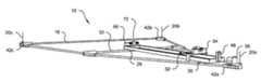
- FIG. 1is a top perspective view of a portion of an aerial support structure in accordance with a preferred embodiment of the present invention, with certain support cables and cords omitted for clarity;
- FIG. 2is a schematic top plan view of a portion of the aerial support structure shown in FIG. 1 , with certain support cables and cords omitted for clarity;
- FIG. 3is a schematic top plan view of a portion of the aerial support structure shown in FIG. 1 , with a camera platform and support cables shown in a modified location for ease of illustration and explanation;
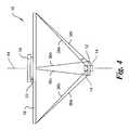
- FIG. 4is a side elevation view of the aerial support structure shown in FIG. 1 mounted in a venue;
- FIG. 5is an enlarged top perspective view of a portion of the aerial support structure shown in FIG. 1 ;
- FIG. 6is an enlarged top perspective view of a portion of the aerial support structure shown in FIG. 1 , with certain support cords omitted for clarity;
- FIG. 7is an enlarged top perspective view of a portion of the aerial support structure shown in FIG. 1 ;
- FIG. 8is an enlarged top plan view of several pulleys of the aerial support structure shown in FIG. 1 ;
- FIG. 9is an enlarged perspective view of yet another portion of the aerial support structure shown in FIG. 1 ;
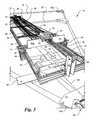
- FIG. 10is a top perspective view of a portion of the aerial support structure shown in FIG. 1 ;
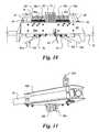
- FIG. 11is a bottom perspective view of a portion of the aerial support structure shown in FIG. 1 ;
- FIG. 12is an enlarged bottom perspective view of a portion of the aerial support structure shown in FIG. 1 ;
- FIG. 13is a block diagram of a control system of the aerial support structure shown in FIG. 1 .
- FIGS. 1-13there is shown in FIGS. 1-13 an aerial support structure, generally designated as “ 10 ,” in accordance with a preferred embodiment of the present invention.
- the aerial support structure 10provides for the selective and stable vertical raising and/or lowering of a platform, such as a camera platform 12 supporting a camera 14 (shown in phantom above and/or below the camera platform 12 in FIG. 4 ), with respect to a ground surface (not shown) (i.e., the floor of a gymnasium) and/or a support platform 18 spaced a predetermined distance above the ground surface.
- a platformsuch as a camera platform 12 supporting a camera 14 (shown in phantom above and/or below the camera platform 12 in FIG. 4 ), with respect to a ground surface (not shown) (i.e., the floor of a gymnasium) and/or a support platform 18 spaced a predetermined distance above the ground surface.
- a ground surfacenot shown
- portions of the aerial support structure 10can be prefabricated and/or pre
- the support platform 18preferably defines a generally equilateral triangle when viewed from above or below ( FIGS. 2 and 3 ).
- three spaced-apart vertices or assembled joints 42 a , 42 b , 42 c of the support platform 18provide an inherently stable structure from which to suspend the camera platform 12 .
- the shape of the support platform 18provides a Steward platform that allows for six degrees of freedom of the camera platform 12 (x, y, z, pitch, roll and yaw).
- the support platform 18is constructed of a plurality of bars or rods that, when properly assembled, form a type of push-pin construction, which is generally inexpensive to produce and simple for a technician to assemble and may be prefabricated away from the venue.
- the platform 18is not limited to such a configuration, as the support platform 18 may be a generally solid or integral piece.
- the support platform 18is mounted to a portion of a ceiling, roof, rafter, joist or girder (not shown) of a venue or arena.
- each vertex 42 a , 42 b , 42 c of the support platform 18may be attached or connected to the ceiling of a venue by a vertically-extending tension cable 20 a , 20 b , 20 c that allows the support platform 18 to be selectively raised and/or lowered in parallel with respect to the ceiling, such that maintenance may be performed on the aerial support structure 10 at the ground surface 16 (see FIG. 1 ).
- the support platform 18is not limited to being a separate structure from the ceiling, roof or rafters of the venue.
- the support platform 18may simply be constructed from three generally equally spaced-apart points on the ceiling, roof or rafters, which generally form an equilateral triangle when viewed from above or below.
- the aerial support structure 10preferably includes a frame or tray 22 mounted to the support platform 18 .
- the frame 22has a generally rectangular configuration when viewed from above or below, but the frame 22 is not limited to such a shape.
- a first end 24 of the frame 22is positioned generally proximate or adjacent to one of the three vertices 42 , and preferably the first vertex 42 a , of the support platform 18 .
- a second end 26 of the frame 22which is generally opposite the first end 24 , is preferably positioned generally proximate or adjacent to a geometric center 28 of the support platform 18 .
- the first end 24 of the frame 22is fixedly attached to a first crossbar 30 that extends between an approximate end-portion of two of the rods of the support platform 18 .
- a second crossbar 32which extends generally between an approximate mid-portion of the same two rods of the support platform 18 to which the first crossbar 30 is attached, preferably supports the second end 26 of the frame 22 on the support platform 18 .
- the aerial support structure 10preferably includes a beam 34 movably attached to the frame 22 .
- opposing end portions of the beam 34are attached or connected to the frame 22 by at least one roller or bearing 40 ( FIGS. 5 and 6 ), such that the beam 34 is slidable on the frame 22 from a first position (see FIG. 5 ), generally proximate or adjacent to the first end 22 of the frame 22 , to a second position (not shown), generally proximate or adjacent to the second end 26 of the frame 22 .
- a longitudinal axis of the beam 34is preferably generally perpendicular to a longitudinal axis of the frame 22 .
- the frame 22may include one or more stops or abutments 46 to prevent or inhibit movement of the beam 34 beyond the first and second positions.
- the camera platform 12is preferably suspended and axially spaced from the support platform 18 by a plurality of spaced-apart support cables 36 .
- the support cables 36are typically held in tension by the force of gravity due to the suspension of the camera platform 12 from the support platform 18 .
- the plurality of support cables 36are comprised of a first support cable 36 a , a second support cable 36 b , a third support cable 36 c , a fourth support cable 36 d , a fifth support cable 36 e and a sixth support cable 36 f ( FIGS. 3 , 4 and 7 - 12 ).
- the six support cables 36provide stability between the support platform 18 and the camera platform 12 and provide safety in suspending the camera platform 12 from the support platform 18 , such that even if five of the six support cables 36 are severed, the remaining support cable 36 will continue to support the camera platform 12 relative to the support platform 18 .
- the camera platform 12is not limited to being suspended from the support platform 18 by the six support cables 36 , but may be suspended from the support platform 18 by a lesser or greater number support cables 36 .
- the camera platform 12may be suspended from some other arena structure, such as a scoreboard, that permits vertical movement of the camera platform 12 between a raised or storage position and a lowered or deployed position.
- the support cables 36are relatively thin and may be approximately one millimeter (mm) or less in diameter.
- the support cables 36may be constructed of a clear monofilament line, similar to that used as fishing line or may be comprised of fiber optic cables to transmit signals to and from the camera platform 12 , a controller 86 ( FIG. 13 ) or any other payload on the support platform 18 or related to the aerial support structure 10 .
- the camera platform 12has the shape of a generally equilateral triangle (see FIG. 3 ), when viewed from above or below, to match the preferred shape of the support platform 18 .
- a geometric center of the camera platform 12is preferably generally directly below the geometric center 28 of the support platform 18 .
- the support platform 18 and camera platform 12are coaxially mounted on a camera axis 44 ( FIG. 4 ), which is a vertical imaginary axis that extends through the geometric center of both the support platform 18 and the camera platform 12 . As shown in FIG.
- each vertex of the camera platform 12preferably points toward generally a mid-point of a direct line between two vertices 42 of the support platform 18 .
- an overall size and/or a top surface area of the camera platform 12be considerably smaller than that of the support platform 18 to increase the stability of the camera platform 12 .
- the camera 14is designed to capture images of a desired target.
- the camera 14may be a still camera for taking still images, a video camera for taking video images, or a combined still and video camera for taking still and video images.
- the camera 14may be preferably moveably mounted to the camera platform 12 to provide flexibility and adaptability to a user in selecting areas within the venue to target for image capture.
- the camera 14is able to pan, tilt and zoom for capturing images virtually anywhere in the venue or wherever the aerial support structure 10 is mounted to capture images.
- the aerial support structure 10preferably includes an actuator 38 mounted to one of the support platform 18 and the frame 22 to effectuate vertical movement of the camera platform 12 via the support cables 36 .
- movement of the actuator 38causes the beam 34 to move with respect to the frame 22 , thereby moving the camera platform 12 relative to the support platform 18 .
- the combination of the single actuator 38 and beam 34increases an effective length of each support cable 36 without having to increase the actual length of each support cable 36 .
- a smaller aerial support structure 10is produced with support cables 36 of shorter length, as compared to the prior art.
- the actuator 38operatively controls a cord 58 ( FIGS. 5 and 6 ) that allows a user to selectively effectuate sliding movement of the beam 34 on the frame 22 , which, in turn, effectuates vertical movement of the camera platform 12 relative to the support platform 18 .
- the single actuator 38is attached to the vertex 42 a of the support platform 18 proximate the first end 24 of the frame 22 and is operatively connected to each of the plurality of support cables 36 .
- the actuator 38is preferably a winch, but may be virtually any device that can selectively raise and/or lower the camera platform 12 .
- the actuator 38may be mechanically/electrically driven or may be manually driven by an operator located on the support platform 18 or ground surface 16 .
- a guide pulley 52is rotatably mounted to the frame 22 between generally the first and second ends 24 , 26 thereof.
- the guide pulley 52is preferably positioned above the frame 22 and is offset from the longitudinal axis of the frame 22 .
- the guide pulley 52may be located in virtually any location, such as below the frame 22 , that accomplishes the functions of the guide pulley 52 discussed herein.
- the guide pulley 52preferably includes a wheel with a single groove therein, but the guide pulley 52 may have two or more wheels and/or grooves as deemed necessary.
- the wheel(s) and groove(s) of the guide pulley 52are preferably generally parallel to the longitudinal axis of the frame 22 , but may be angled slightly with respect to the longitudinal axis of the frame 22 .
- a first end of the cord 58is fixedly attached to the actuator 38 and a portion of the cord 58 extends from the actuator 38 and around at least a portion of the guide pulley 52 .
- FIG. 1A first end of the cord 58 is fixedly attached to the actuator 38 and a portion of the cord 58 extends from the actuator 38 and around at least a portion of the guide pulley 52 .
- the cord 58wraps around a portion of the groove(s) of the guide pulley 52 such that the guide pulley 52 redirects the cord 58 back toward actuator 38 at a slight angle, such as five degrees, offset from a plane defined by the taut cord 58 extending between the actuator 38 and the guide pulley 52 .
- a set pulley 53be rotatably mounted to the frame 22 generally at or proximate to the first end 24 thereof.
- the set pulley 53is preferably positioned above the frame 22 and is located generally along the longitudinal axis of the frame 22 .
- the set pulley 53may be located in virtually any location, such as below the frame 22 , that accomplishes the functions of the set pulley 53 discussed herein. It is preferred that the set pulley 53 includes a wheel with a single groove therein, but the set pulley 53 may have two or more wheels and/or grooves as deemed necessary.
- the wheel(s) and groove(s) of the set pulley 53are preferably generally parallel to the longitudinal axis of the frame 22 , but may be angled slightly with respect to the longitudinal axis of the frame 22 .
- a portion of the cord 58extends from the guide pulley 52 and wraps around at least a portion of the set pulley 53 . Specifically, as shown in FIGS.
- the cord 58wraps around a portion of the groove(s) of the set pulley 53 such that the set pulley 53 redirects the cord 58 back toward the second end 26 of the frame 22 at a slight angle, such as five degrees, offset from a plane defined by the taut cord 58 extending between the guide pulley 52 and the set pulley 53 .
- a preferred embodiment of the aerial support structure 10includes a brace 48 that extends vertically from the first end 24 of the frame 22 .
- a first or lower end of the brace 48is fixedly attached to the frame 22 and a second or upper end of the brace 48 includes at least one base pulley 50 rotatably attached thereto.
- the base pulley 50may be comprised of a single wheel with a groove therein or a plurality of wheels, in parallel or in a side-by-side configuration, each having a groove therein.
- the wheel(s) and groove(s) of the base pulley 50are preferably generally parallel to the longitudinal axis of the frame 22 , but the wheel(s) and groove(s) may be angled slightly with respect to the longitudinal axis of the frame 22 .
- a first bracket 54is mounted to a top surface of the beam 34 .
- a generally planar first sidewall 60 a of the first bracket 54which preferably faces toward the actuator 38 , includes at least one pedestal pulley 56 rotatably mounted thereto. It is preferred that the pedestal pulley 56 includes the same number of wheels and grooves as the base pulley 50 .
- the cord 58extends from the set pulley 53 on the frame 22 and wraps around at least a portion of the pedestal pulley 56 .
- the taut cord 58engages at least a portion of one of the grooves of the pedestal pulley 56 , such that the groove(s) redirect(s) the cord 58 at a slight angle, such as five degrees, offset from a plane defined by the taut cord 58 extending between the set pulley 53 and the pedestal pulley 56 . From there, the taut cord 58 extends to and around at least a portion of the base pulley 50 on the brace 48 .
- the cord 58extends to and around at least a portion of the pedestal pulley 56 and then back to and around the base pulley 50 , such that the cord 58 is wrapped or looped around the pedestal pulley 56 and base pulley 50 .
- the consecutive groove-by-groove wrapping or looping of the cord 58preferably occurs several times, such as seven iterations.
- a second end of the cord 58is preferably fixed to a portion of the pedestal pulley 56 , such as in one of the end grooves of the pedestal pulley 56 .
- rotation of the actuator 38reels in or reels out the cord 58 , which extends around at least a portion of the guide pulley 52 , which then extends around at least a portion of the set pulley 53 , which then consecutively extends around at least a portion of the pedestal pulley 56 and base pulley 50 , which, in turn, causes the beam 34 to slide with respect to the frame 22 .
- a generally planar second sidewall 60 b ( FIG. 6 ) of the first bracket 54which generally opposes the first sidewall 60 a , includes at least one first transport pulley 62 rotatably mounted thereto.
- the at least one first transport pulley 62may be comprised of a single wheel with a groove therein or a plurality of wheels in a side-by-side or co-linear configuration, each having a groove therein.
- the wheel(s) and groove(s) of the first transport pulley(s) 62are preferably generally parallel to the longitudinal axis of the frame 22 , but the wheels(s) and groove(s) may be angled slightly with respect to the longitudinal axis of the frame 22 .
- six independent first transport pulleys 62are placed in parallel or in a side-by-side configuration.
- the aerial support structure 10may contain a greater or fewer number of first transport pulleys 62 as deemed necessary.
- At least one first central pulley 64is rotatably attached to the second sidewall 60 b of the first bracket 54 and divides the six independent first transport pulleys 62 in half, such that three first transport pulleys 62 are located on either side of the first central pulley 64 .
- the first central pulley 64 and each of the six first transport pulleys 62share a common axis of rotation 74 ( FIG. 7 ).
- a second bracket 66is mounted to a top surface of the frame 22 proximate the second end 26 thereof.
- the second bracket 66is preferably substantially similar to the first bracket 54 , but has the opposite orientation as that of the first bracket 54 .
- a generally planar first sidewall 68 a of the second bracket 66faces away from the actuator 38
- a generally planar second sidewall 68 b of the second bracket 66faces toward the actuator 38 and the second sidewall 60 b of the first bracket 54 .
- the second sidewall 68 b of the second bracket 66which generally opposes the first sidewall 68 a , preferably includes at least one second transport pulley 70 rotatably mounted thereto.
- the at least one second transport pulley 70may be comprised of a single wheel with a groove therein or a plurality of wheels in a side-by-side or co-linear configuration, each having a groove therein.
- the groove(s) of the second transport pulley(s) 70is/are preferably generally parallel to the longitudinal axis of the frame 22 , but the groove(s) may be angled slightly with respect to the longitudinal axis of the frame 22 .
- each of the six second transport pulleys 70are placed in parallel or in a side-by-side configuration.
- the aerial support structure 10may contain a greater or fewer number of second transport pulleys 70 as deemed necessary.
- at least one second central pulley 72is rotatably attached to the second sidewall 68 b of the second bracket 66 and divides the six independent second transport pulleys 70 in half, such that three second transport pulleys 70 are located on either side of the second central pulley 72 .
- the second central pulley 72 and each of the six second transport pulleys 70share a common axis of rotation 76 ( FIG. 9 ).
- a first end of each of the six support cables 36 a , 36 b , 36 c , 36 d , 36 e , 36 fis preferably fixedly attached to one of the six first transport pulleys 62 , such as in an end groove of one of the six first transport pulleys 62 .
- a second end of each of the six support cables 36 a , 36 b , 36 c , 36 d , 36 e , 36 fis preferably fixedly attached to one vertex of the camera platform 12 .
- each of the six support cables 36 a , 36 b , 36 c , 36 d , 36 e , 36 fpreferably wraps or loops around one of the six first transport pulleys 62 and the six second transport pulleys 70 similar in manner to the wrapping of the cord 58 around the pedestal pulley 56 and base pulley 50 described above.
- the aerial support structure 10preferable includes at least one directional pulley 78 mounted to a lower or bottom side of the frame 22 proximate the second end 26 thereof.
- a directional pulley 78mounted to a lower or bottom side of the frame 22 proximate the second end 26 thereof.
- six independent directional pulleys 78are rotatably mounted on the bottom side of the frame 22 , each directional pulley 78 being mounted generally vertically below one of the six second transport pulleys 70 .
- an axis of rotation of each directional pulley 78extends generally in a direction that is non-parallel to or offset from the axis of rotation 74 of each of second transport pulleys 70 . As shown in FIG.
- the offset angle between a cooperating pair of directional pulleys 78 and the second transport pulleys 70is greater for the two outside pair of directional pulleys 78 (corresponding to support cables 36 a , 36 b and 36 e , 36 f , respectively) than it is for the pair of middle directional pulleys 78 (corresponding to support cables 36 c , 36 d ).
- At least one opening or passageway 80extends through a portion of the second end 26 of the frame 22 and/or a lower end of the second bracket 66 .
- six spaced-apart openings 80extend generally across the second end 26 of the frame 22 .
- Each opening 80is preferably positioned vertically below an end groove of each of the six second transport pulleys 70 and is sized and shaped to receive at least a portion of one of the six support cables 36 a , 36 b , 36 c , 36 d , 36 e , 36 f therethrough.
- each of the six support cables 36 a , 36 b , 36 c , 36 d , 36 e , 36 fpreferably extends, wraps or loops around both the first and second transport pulleys 62 , 70 four times, such that each support cable 36 wraps or loops around the first and second transport pulleys 62 , 70 and rests or sits within a separate and consecutive groove of each transport pulley 62 , 70 .
- each support cable 36 a , 36 b , 36 c , 36 d , 36 e , 36 fextends around a portion of the fourth or end groove of the second transport pulley 72
- each support cable 36 a , 36 b , 36 c , 36 d , 36 e , 36 fextends through one of the openings 80 to one of the six directional pulleys 78 .
- each of the six directional pulley 78is preferably angled toward one of the vertexes (vertices) of the camera platform 12 .
- the center pair of directional pulleys 78(corresponding to support cables 36 c , 36 d ) are angled or directed toward the same vertex of the camera platform 12 .
- the two outside pairs of directional pulleys 78(corresponding to support cables 36 a , 36 b and 36 e , 36 f , respectively) are also angled or directed toward the same vertex of the camera platform 12 .
- each support cable 36extends at an angle ⁇ with respect to vertical camera axis 44 . The angle ⁇ provides increased stability to the camera platform 12 .
- a transport cable 82extends, wraps or loops around both the first and second central pulleys 64 , 72 several times, such that the transport cable 82 wraps or loops around the first and second central pulleys 64 , 72 and rests or sits within a separate and consecutive groove of each pulley 64 , 72 .
- a first end of the transport cable 82is operatively connected to a circuit board 84 mounted to one of the frame 22 and support platform 18
- a second end of the transport cable 82is operatively connected to one of the camera 14 and camera platform 12 .
- the transport cable 82preferably sends electrical operational signals to the camera 14 and/or camera platform 12 .
- the preferred transport cable 82is comprised of a fiber optic cable that provides signals, such as control information, transmits signals, such as images, and/or provides power to the camera 14 .
- the transport cable 82may be constructed of a steel cable, for example, that is mounted directly to the first central pulley 64 and/or the support platform 18 at one end, and the camera 14 at an opposite end to provide a fail-safe or safety cable in the event that each of the support cables 36 are severed, thereby preventing the camera 14 and camera platform 12 from falling or becoming disengaged from the support platform 18 .
- the controller 86which is preferably mounted to one of the frame 22 and support platform 18 , is operatively connected to at least one of the camera 14 , the actuator 38 , a radio frequency device 88 , a battery 90 , a sensor 92 , a broadcast truck or control room 94 and an advertising medium 96 .
- the advertising medium 96may be mounted to the support platform 18 and/or the camera platform 12 , and is comprised of, for example, a banner with a printed advertisement thereon.
- the advertising mediummay be signage with a backlit image, a projector that projects images onto a banner, the venue, the camera platform 12 or the support platform 18 , an electronically controlled sign or nearly any other advertising medium that is able to convey an advertising message to persons, such as patrons within the venue.
- the battery 90is mounted to one of the support platform 18 and the frame 22 to provide power to at least the camera 14 .
- the controller 86 and radio frequency device(s) 88are mounted to the support platform 18 or frame 22 for storing images captured by the camera 14 and transmitting images from the camera 14 to the controller 86 , respectively.
- the radio frequency device(s) 88may also be utilized to transmit command signals from the controller 86 to the camera 14 or command signals from the controller 86 to the actuator 38 or the advertising medium 96 .
- the aerial support structure 10is not limited to the inclusion of a controller 86 , radio frequency device 88 and advertising medium 96 , but these structures may be mounted to other portions of the aerial support structure 10 or nearly anywhere inside or outside of the venue.
- the controller 86may provide stability to the images for the aerial support structure 10 by controlling the acceleration and deceleration of the actuator 38 and movement of the camera 14 during various conditions. For example, controlling the rate of acceleration and deceleration of the movement of the camera platform 12 relative to the support platform 18 through the actuator 38 will typically increase stability by reducing any jumpiness or vibration between the camera platform 12 and the support platform 18 .
- the controller 86may be in communication with the sensor(s) 92 , which include optical sensors, accelerometers, inertial sensors, inclinometers, anemometers, thermometers, vibration meters, strain gauges or other similar sensors and are able to sense movement of the camera 14 , camera platform 12 and/or support platform 18 or various environmental conditions. As a result, the controller 86 is able to react to the information received from the sensor(s) 92 to stabilize the aerial support structure 10 .
- the aerial support structure 10is preferably mounted in the venue, typically a sporting arena.
- the arenapreferably includes an observed area, a seating area and a line of sight from the seating area to the observed area.
- the support platform 18 and camera platform 12are preferably mounted outside of each line of sight or are programmed to prevent movement into each of the lines of sight of the venue or arena. Accordingly, persons, such as patrons in the seating area, are able to observe events or other activities occurring in all portions of the observed area within their line of sight without their view being obstructed by the support platform 18 and/or camera platform 12 .
- the preferred embodiments of the aerial support structure 10may capture video and still images at sporting events, providing security, video and still images at conventions, aquatic observation and monitoring of hazardous clean-up sites or other similar uses. It is understood, therefore, that this invention is not limited to the particular embodiments disclosed, but is intended to cover modifications within the spirit and scope of the present invention as defined by the present disclosure and/or the appended claims.
Landscapes
- Physics & Mathematics (AREA)
- General Physics & Mathematics (AREA)
- Studio Devices (AREA)
Abstract
Description
Claims (15)
Priority Applications (1)
| Application Number | Priority Date | Filing Date | Title |
|---|---|---|---|
| US12/905,700US8251597B2 (en) | 2009-10-16 | 2010-10-15 | Aerial support structure for capturing an image of a target |
Applications Claiming Priority (2)
| Application Number | Priority Date | Filing Date | Title |
|---|---|---|---|
| US27915509P | 2009-10-16 | 2009-10-16 | |
| US12/905,700US8251597B2 (en) | 2009-10-16 | 2010-10-15 | Aerial support structure for capturing an image of a target |
Publications (2)
| Publication Number | Publication Date |
|---|---|
| US20110091196A1 US20110091196A1 (en) | 2011-04-21 |
| US8251597B2true US8251597B2 (en) | 2012-08-28 |
Family
ID=43879374
Family Applications (1)
| Application Number | Title | Priority Date | Filing Date |
|---|---|---|---|
| US12/905,700Expired - Fee RelatedUS8251597B2 (en) | 2009-10-16 | 2010-10-15 | Aerial support structure for capturing an image of a target |
Country Status (1)
| Country | Link |
|---|---|
| US (1) | US8251597B2 (en) |
Cited By (4)
| Publication number | Priority date | Publication date | Assignee | Title |
|---|---|---|---|---|
| US8544788B1 (en)* | 2010-07-07 | 2013-10-01 | Captures, LLC | Aerostat assembly |
| US20140312808A1 (en)* | 2013-04-19 | 2014-10-23 | Randall Lee Szarzynski | Multi-dimensional positioning of an object |
| US20160184719A1 (en)* | 2014-12-24 | 2016-06-30 | Verity Studios Ag | Flexibly supported movable platform |
| US11435649B2 (en) | 2009-12-23 | 2022-09-06 | Cablecam, Llc | Apparatus and method for calibrating an aerial movement system |
Families Citing this family (4)
| Publication number | Priority date | Publication date | Assignee | Title |
|---|---|---|---|---|
| US8199197B2 (en)* | 2008-02-20 | 2012-06-12 | Actioncam. LLC | Aerial camera system |
| US9477141B2 (en) | 2011-08-31 | 2016-10-25 | Cablecam, Llc | Aerial movement system having multiple payloads |
| US9337949B2 (en) | 2011-08-31 | 2016-05-10 | Cablecam, Llc | Control system for an aerially moved payload |
| CN112345537B (en)* | 2020-11-02 | 2024-03-15 | 上海交大海科检测技术有限公司 | Appearance detection platform suitable for tunnel |
Citations (70)
| Publication number | Priority date | Publication date | Assignee | Title |
|---|---|---|---|---|
| US367610A (en) | 1887-08-02 | James faieman | ||
| US1300716A (en) | 1918-08-22 | 1919-04-15 | John Frolek | Observation-camera mount. |
| WO1984002199A1 (en) | 1982-12-01 | 1984-06-07 | Garrett W Brown | Improved suspension system for supporting and conveying equipment, such as a camera |
| US4657267A (en)* | 1984-09-19 | 1987-04-14 | Sachtler Gmbh Filmtechnische Geraete | Motion picture or television camera stand |
| US4858000A (en) | 1988-09-14 | 1989-08-15 | A. C. Nielsen Company | Image recognition audience measurement system and method |
| US5034759A (en)* | 1989-11-28 | 1991-07-23 | Ronald Watson | Photo device |
| US5225863A (en) | 1991-08-15 | 1993-07-06 | Weir Jones Iain | Remotely operated camera system with battery recharging system |
| US5224426A (en) | 1991-11-13 | 1993-07-06 | Cablecam Systems Ltd. | Aerial cableway and method for filming subjects in motion |
| WO1995019903A1 (en) | 1994-01-21 | 1995-07-27 | James Rodnunsky | Novel aerial cableway and method for filming subjects in motion |
| WO1995023053A1 (en) | 1994-02-28 | 1995-08-31 | Mcdonnell Douglas Corporation | Tendon suspended platform robot |
| US5448290A (en) | 1991-08-23 | 1995-09-05 | Go-Video Inc. | Video security system with motion sensor override, wireless interconnection, and mobile cameras |
| US5508737A (en) | 1994-07-06 | 1996-04-16 | Sony Corporation | Remote video viewing and recording system for remotely occurring events |
| US5568189A (en)* | 1994-06-21 | 1996-10-22 | Kneller; Paul J. | Aerial support platform mechanism with five axes of motion |
| US5602760A (en) | 1994-02-02 | 1997-02-11 | Hughes Electronics | Image-based detection and tracking system and processing method employing clutter measurements and signal-to-clutter ratios |
| EP0764927A1 (en) | 1995-09-22 | 1997-03-26 | C.P. Synergie | Video surveillance system |
| US5655053A (en) | 1994-03-08 | 1997-08-05 | Renievision, Inc. | Personal video capture system including a video camera at a plurality of video locations |
| US5751885A (en) | 1995-12-19 | 1998-05-12 | O'loughlin; Maureen | Centralized video system |
| US5752088A (en)* | 1997-02-03 | 1998-05-12 | Desselle; Alex S. | Aerial photography device |
| US5771307A (en) | 1992-12-15 | 1998-06-23 | Nielsen Media Research, Inc. | Audience measurement system and method |
| US5784966A (en) | 1996-06-19 | 1998-07-28 | Garrett W. Brown | Stabilized lightweight equipment transport system |
| USRE36041E (en) | 1990-11-01 | 1999-01-12 | Massachusetts Institute Of Technology | Face recognition system |
| US5946444A (en) | 1993-08-24 | 1999-08-31 | Lucent Technologies, Inc. | System and method for creating personalized image collections from multiple locations by using a communications network |
| JP2000032325A (en) | 1998-07-10 | 2000-01-28 | Fuji Photo Optical Co Ltd | Photographing device |
| US6145679A (en) | 1996-02-07 | 2000-11-14 | Walters; Victor | Shiftable tail-block logging skyline |
| US6359647B1 (en) | 1998-08-07 | 2002-03-19 | Philips Electronics North America Corporation | Automated camera handoff system for figure tracking in a multiple camera system |
| JP2002152720A (en) | 2000-11-15 | 2002-05-24 | Matsushita Electric Ind Co Ltd | Video recording device |
| US20020085762A1 (en) | 2000-11-02 | 2002-07-04 | Image Id Ltd. | Mass event image identification |
| US20020149681A1 (en) | 2001-03-28 | 2002-10-17 | Kahn Richard Oliver | Automatic image capture |
| US6490409B1 (en) | 1996-10-08 | 2002-12-03 | Verizon Laboratories Inc. | System and method for making a personal photographic collection |
| US20020197074A1 (en) | 1997-10-22 | 2002-12-26 | Adrian Gluck & Associates, Inc. | Imaging system and method |
| US20030023452A1 (en) | 2001-07-30 | 2003-01-30 | Eastman Kodak Company | System and process for offering imaging services |
| JP2003030833A (en) | 2001-07-13 | 2003-01-31 | Matsushita Electric Ind Co Ltd | Optical recording medium, recording method for optical recording medium, and recording apparatus for optical recording medium |
| US20030040943A1 (en) | 2001-08-22 | 2003-02-27 | International Business Machines Corporation | System and method for selecting arena seat locations for display |
| US6532345B1 (en) | 1994-08-02 | 2003-03-11 | L. N. C. J. Limited | Imaging system and method |
| US6542621B1 (en) | 1998-08-31 | 2003-04-01 | Texas Instruments Incorporated | Method of dealing with occlusion when tracking multiple objects and people in video sequences |
| GB2380883A (en) | 2001-06-20 | 2003-04-16 | Roke Manor Research | Location and identification of participants in a sporting event by means of optically readable tags |
| JP2003125320A (en) | 2001-10-12 | 2003-04-25 | Ricoh Co Ltd | Digital camera image output method |
| JP2003143350A (en) | 2001-08-24 | 2003-05-16 | Matsushita Electric Ind Co Ltd | Photographed image transmission system and photographed image transmission method |
| US6591068B1 (en) | 2000-10-16 | 2003-07-08 | Disney Enterprises, Inc | Method and apparatus for automatic image capture |
| US6608563B2 (en) | 2000-01-26 | 2003-08-19 | Creative Kingdoms, Llc | System for automated photo capture and retrieval |
| WO2003069821A1 (en) | 2002-02-14 | 2003-08-21 | American Management Systems,Inc. | A user authentication system and methods thereof |
| JP2003244685A (en) | 2002-02-15 | 2003-08-29 | Mitsubishi Heavy Ind Ltd | Monitor device and monitor method |
| US6618075B2 (en) | 1996-12-09 | 2003-09-09 | Sony Corporation | Amusement ride camera system for shooting pictures |
| US20030190076A1 (en) | 2002-04-05 | 2003-10-09 | Bruno Delean | Vision-based operating method and system |
| US6690374B2 (en) | 1999-05-12 | 2004-02-10 | Imove, Inc. | Security camera system for tracking moving objects in both forward and reverse directions |
| US20040028391A1 (en) | 2002-06-13 | 2004-02-12 | David Black | Internet video surveillance camera system and method |
| US6697502B2 (en) | 2000-12-14 | 2004-02-24 | Eastman Kodak Company | Image processing method for detecting human figures in a digital image |
| US20040085334A1 (en) | 2002-10-30 | 2004-05-06 | Mark Reaney | System and method for creating and displaying interactive computer charcters on stadium video screens |
| US20040135902A1 (en) | 2003-01-09 | 2004-07-15 | Eventshots.Com Incorporated | Image association process |
| US6775411B2 (en) | 2002-10-18 | 2004-08-10 | Alan D. Sloan | Apparatus and method for image recognition |
| US20040193493A1 (en) | 1999-10-08 | 2004-09-30 | King Budde B. | Advertising system and method |
| ES2215454A1 (en) | 2002-04-19 | 2004-10-01 | Valero Vision, S.A. | Suspension system for controlling mobility of film camera i.e. video camera, in e.g. theaters, has pulleys attached with support assemblies, and motor placed at floor level for convergingdifferent wires in auxiliary stabilizer of chamber |
| JP2004289434A (en) | 2003-03-20 | 2004-10-14 | Fuji Photo Film Co Ltd | Photographing system |
| US20040201738A1 (en) | 2001-11-13 | 2004-10-14 | Tabula Rasa, Inc. | Method and apparatus for providing automatic access to images captured at diverse recreational venues |
| US6809495B2 (en) | 2003-07-28 | 2004-10-26 | Cablecam International Inc. | System and method for moving objects within three-dimensional space |
| US6809762B1 (en) | 2001-01-22 | 2004-10-26 | Brett James Donnelly | Multiple photograph service method and apparatus |
| US20040218918A1 (en) | 1994-08-02 | 2004-11-04 | Media Technologies Licensing Llc | Imaging system and method |
| US6819783B2 (en) | 1996-09-04 | 2004-11-16 | Centerframe, Llc | Obtaining person-specific images in a public venue |
| JP2004356683A (en) | 2003-05-27 | 2004-12-16 | Fuji Photo Film Co Ltd | Image management system |
| US20050024005A1 (en) | 2003-07-28 | 2005-02-03 | Jim Rodnunsky | System and method for facilitating fluid three-dimensional movement of an object via directional force |
| US20050024004A1 (en) | 2003-07-28 | 2005-02-03 | Cablecam International Inc. | Cabling system and method for facilitating fluid three-dimensional movement of a suspended camera |
| WO2005027023A1 (en) | 2003-09-12 | 2005-03-24 | Stratech Systems Limited | A method and system for monitoring the movement of people |
| US6873355B1 (en) | 1998-08-07 | 2005-03-29 | Skycam, Llc | Three-dimensional moving camera assembly with an informational cover housing |
| US20050068165A1 (en) | 2003-09-26 | 2005-03-31 | General Electric Company | System and method of providing security for a site |
| US6886471B2 (en) | 2003-02-18 | 2005-05-03 | Cablecam International Inc. | Traveling highline system |
| WO2005042385A2 (en) | 2003-10-25 | 2005-05-12 | Cablecam International Inc. | A mounting system reeved to move an object in two-dimensions and methods relating to same |
| US20070047949A1 (en) | 1996-02-27 | 2007-03-01 | Media Technologies Licensing, Inc. | Imaging system and method |
| WO2007030665A2 (en) | 2005-09-07 | 2007-03-15 | Ablaze Development Corporation | Aerial support structure and method for image capture |
| US20070064208A1 (en)* | 2005-09-07 | 2007-03-22 | Ablaze Development Corporation | Aerial support structure and method for image capture |
| US20090103909A1 (en)* | 2007-10-17 | 2009-04-23 | Live Event Media, Inc. | Aerial camera support structure |
- 2010
- 2010-10-15USUS12/905,700patent/US8251597B2/ennot_activeExpired - Fee Related
Patent Citations (75)
| Publication number | Priority date | Publication date | Assignee | Title |
|---|---|---|---|---|
| US367610A (en) | 1887-08-02 | James faieman | ||
| US1300716A (en) | 1918-08-22 | 1919-04-15 | John Frolek | Observation-camera mount. |
| WO1984002199A1 (en) | 1982-12-01 | 1984-06-07 | Garrett W Brown | Improved suspension system for supporting and conveying equipment, such as a camera |
| US4710819A (en) | 1982-12-01 | 1987-12-01 | Brown Garrett W | Suspension system for supporting and conveying equipment, such as a camera |
| US4657267A (en)* | 1984-09-19 | 1987-04-14 | Sachtler Gmbh Filmtechnische Geraete | Motion picture or television camera stand |
| US4858000A (en) | 1988-09-14 | 1989-08-15 | A. C. Nielsen Company | Image recognition audience measurement system and method |
| US5034759A (en)* | 1989-11-28 | 1991-07-23 | Ronald Watson | Photo device |
| USRE36041E (en) | 1990-11-01 | 1999-01-12 | Massachusetts Institute Of Technology | Face recognition system |
| US5225863A (en) | 1991-08-15 | 1993-07-06 | Weir Jones Iain | Remotely operated camera system with battery recharging system |
| US5448290A (en) | 1991-08-23 | 1995-09-05 | Go-Video Inc. | Video security system with motion sensor override, wireless interconnection, and mobile cameras |
| US5224426A (en) | 1991-11-13 | 1993-07-06 | Cablecam Systems Ltd. | Aerial cableway and method for filming subjects in motion |
| US5771307A (en) | 1992-12-15 | 1998-06-23 | Nielsen Media Research, Inc. | Audience measurement system and method |
| US5946444A (en) | 1993-08-24 | 1999-08-31 | Lucent Technologies, Inc. | System and method for creating personalized image collections from multiple locations by using a communications network |
| WO1995019903A1 (en) | 1994-01-21 | 1995-07-27 | James Rodnunsky | Novel aerial cableway and method for filming subjects in motion |
| US5602760A (en) | 1994-02-02 | 1997-02-11 | Hughes Electronics | Image-based detection and tracking system and processing method employing clutter measurements and signal-to-clutter ratios |
| WO1995023053A1 (en) | 1994-02-28 | 1995-08-31 | Mcdonnell Douglas Corporation | Tendon suspended platform robot |
| US5655053A (en) | 1994-03-08 | 1997-08-05 | Renievision, Inc. | Personal video capture system including a video camera at a plurality of video locations |
| US5568189A (en)* | 1994-06-21 | 1996-10-22 | Kneller; Paul J. | Aerial support platform mechanism with five axes of motion |
| US5508737A (en) | 1994-07-06 | 1996-04-16 | Sony Corporation | Remote video viewing and recording system for remotely occurring events |
| US20040218918A1 (en) | 1994-08-02 | 2004-11-04 | Media Technologies Licensing Llc | Imaging system and method |
| US6532345B1 (en) | 1994-08-02 | 2003-03-11 | L. N. C. J. Limited | Imaging system and method |
| US7077581B2 (en) | 1994-08-02 | 2006-07-18 | Media Technologies Licensing Llc | Imaging system and method |
| EP0764927A1 (en) | 1995-09-22 | 1997-03-26 | C.P. Synergie | Video surveillance system |
| US5751885A (en) | 1995-12-19 | 1998-05-12 | O'loughlin; Maureen | Centralized video system |
| US6145679A (en) | 1996-02-07 | 2000-11-14 | Walters; Victor | Shiftable tail-block logging skyline |
| US20070047949A1 (en) | 1996-02-27 | 2007-03-01 | Media Technologies Licensing, Inc. | Imaging system and method |
| US5784966A (en) | 1996-06-19 | 1998-07-28 | Garrett W. Brown | Stabilized lightweight equipment transport system |
| US6819783B2 (en) | 1996-09-04 | 2004-11-16 | Centerframe, Llc | Obtaining person-specific images in a public venue |
| US6490409B1 (en) | 1996-10-08 | 2002-12-03 | Verizon Laboratories Inc. | System and method for making a personal photographic collection |
| US6618075B2 (en) | 1996-12-09 | 2003-09-09 | Sony Corporation | Amusement ride camera system for shooting pictures |
| US5752088A (en)* | 1997-02-03 | 1998-05-12 | Desselle; Alex S. | Aerial photography device |
| US20020197074A1 (en) | 1997-10-22 | 2002-12-26 | Adrian Gluck & Associates, Inc. | Imaging system and method |
| US6698943B2 (en) | 1997-10-22 | 2004-03-02 | Media Technologies Licensing, Llc. | Imaging system and method |
| JP2000032325A (en) | 1998-07-10 | 2000-01-28 | Fuji Photo Optical Co Ltd | Photographing device |
| US6873355B1 (en) | 1998-08-07 | 2005-03-29 | Skycam, Llc | Three-dimensional moving camera assembly with an informational cover housing |
| US6359647B1 (en) | 1998-08-07 | 2002-03-19 | Philips Electronics North America Corporation | Automated camera handoff system for figure tracking in a multiple camera system |
| US6542621B1 (en) | 1998-08-31 | 2003-04-01 | Texas Instruments Incorporated | Method of dealing with occlusion when tracking multiple objects and people in video sequences |
| US6690374B2 (en) | 1999-05-12 | 2004-02-10 | Imove, Inc. | Security camera system for tracking moving objects in both forward and reverse directions |
| US20040193493A1 (en) | 1999-10-08 | 2004-09-30 | King Budde B. | Advertising system and method |
| US6608563B2 (en) | 2000-01-26 | 2003-08-19 | Creative Kingdoms, Llc | System for automated photo capture and retrieval |
| US6591068B1 (en) | 2000-10-16 | 2003-07-08 | Disney Enterprises, Inc | Method and apparatus for automatic image capture |
| US20020085762A1 (en) | 2000-11-02 | 2002-07-04 | Image Id Ltd. | Mass event image identification |
| JP2002152720A (en) | 2000-11-15 | 2002-05-24 | Matsushita Electric Ind Co Ltd | Video recording device |
| US6697502B2 (en) | 2000-12-14 | 2004-02-24 | Eastman Kodak Company | Image processing method for detecting human figures in a digital image |
| US6809762B1 (en) | 2001-01-22 | 2004-10-26 | Brett James Donnelly | Multiple photograph service method and apparatus |
| US20020149681A1 (en) | 2001-03-28 | 2002-10-17 | Kahn Richard Oliver | Automatic image capture |
| GB2380883A (en) | 2001-06-20 | 2003-04-16 | Roke Manor Research | Location and identification of participants in a sporting event by means of optically readable tags |
| JP2003030833A (en) | 2001-07-13 | 2003-01-31 | Matsushita Electric Ind Co Ltd | Optical recording medium, recording method for optical recording medium, and recording apparatus for optical recording medium |
| US20030023452A1 (en) | 2001-07-30 | 2003-01-30 | Eastman Kodak Company | System and process for offering imaging services |
| US20030040943A1 (en) | 2001-08-22 | 2003-02-27 | International Business Machines Corporation | System and method for selecting arena seat locations for display |
| JP2003143350A (en) | 2001-08-24 | 2003-05-16 | Matsushita Electric Ind Co Ltd | Photographed image transmission system and photographed image transmission method |
| JP2003125320A (en) | 2001-10-12 | 2003-04-25 | Ricoh Co Ltd | Digital camera image output method |
| US20040201738A1 (en) | 2001-11-13 | 2004-10-14 | Tabula Rasa, Inc. | Method and apparatus for providing automatic access to images captured at diverse recreational venues |
| WO2003069821A1 (en) | 2002-02-14 | 2003-08-21 | American Management Systems,Inc. | A user authentication system and methods thereof |
| JP2003244685A (en) | 2002-02-15 | 2003-08-29 | Mitsubishi Heavy Ind Ltd | Monitor device and monitor method |
| US20030190076A1 (en) | 2002-04-05 | 2003-10-09 | Bruno Delean | Vision-based operating method and system |
| ES2215454A1 (en) | 2002-04-19 | 2004-10-01 | Valero Vision, S.A. | Suspension system for controlling mobility of film camera i.e. video camera, in e.g. theaters, has pulleys attached with support assemblies, and motor placed at floor level for convergingdifferent wires in auxiliary stabilizer of chamber |
| US20040028391A1 (en) | 2002-06-13 | 2004-02-12 | David Black | Internet video surveillance camera system and method |
| US6775411B2 (en) | 2002-10-18 | 2004-08-10 | Alan D. Sloan | Apparatus and method for image recognition |
| US20040085334A1 (en) | 2002-10-30 | 2004-05-06 | Mark Reaney | System and method for creating and displaying interactive computer charcters on stadium video screens |
| US20040135902A1 (en) | 2003-01-09 | 2004-07-15 | Eventshots.Com Incorporated | Image association process |
| US6886471B2 (en) | 2003-02-18 | 2005-05-03 | Cablecam International Inc. | Traveling highline system |
| JP2004289434A (en) | 2003-03-20 | 2004-10-14 | Fuji Photo Film Co Ltd | Photographing system |
| JP2004356683A (en) | 2003-05-27 | 2004-12-16 | Fuji Photo Film Co Ltd | Image management system |
| US20050024005A1 (en) | 2003-07-28 | 2005-02-03 | Jim Rodnunsky | System and method for facilitating fluid three-dimensional movement of an object via directional force |
| WO2005013195A2 (en) | 2003-07-28 | 2005-02-10 | Cablecam International Inc. | System for a three dimensional movement |
| US20050024004A1 (en) | 2003-07-28 | 2005-02-03 | Cablecam International Inc. | Cabling system and method for facilitating fluid three-dimensional movement of a suspended camera |
| US6809495B2 (en) | 2003-07-28 | 2004-10-26 | Cablecam International Inc. | System and method for moving objects within three-dimensional space |
| WO2005027023A1 (en) | 2003-09-12 | 2005-03-24 | Stratech Systems Limited | A method and system for monitoring the movement of people |
| US20050068165A1 (en) | 2003-09-26 | 2005-03-31 | General Electric Company | System and method of providing security for a site |
| WO2005042385A2 (en) | 2003-10-25 | 2005-05-12 | Cablecam International Inc. | A mounting system reeved to move an object in two-dimensions and methods relating to same |
| US20050160936A1 (en) | 2003-10-25 | 2005-07-28 | Cablecam International Inc. | Object movement system and method |
| WO2007030665A2 (en) | 2005-09-07 | 2007-03-15 | Ablaze Development Corporation | Aerial support structure and method for image capture |
| US20070064208A1 (en)* | 2005-09-07 | 2007-03-22 | Ablaze Development Corporation | Aerial support structure and method for image capture |
| US20090103909A1 (en)* | 2007-10-17 | 2009-04-23 | Live Event Media, Inc. | Aerial camera support structure |
Non-Patent Citations (7)
| Title |
|---|
| "Java Advanced Imaging (JAI) API", printout from web site: http:/java.sun.com/products/java-media/jai/, printout date: Sep. 4, 2006, 2 pages. |
| "What is Java Advanced Imaging?", printout from web site: http://java.sun.com/products/java-media/jai/whatis.html, printout date: Sep. 4, 2006, 2 pages. |
| Event Pictures Search input screen, printout from web site: http://www.eventpictures.com/app/event/searchEventAdvanced, printout date: Sep. 6, 2006, 1 page. |
| Event Pictures-Sell Photos online, printout from web site: http://www.eventpictures.com/info/sell-photos-online.html, printout date: Sep. 6, 2006, 2 pages. |
| Extended European Search Report, dated Jun. 23, 2009, in EP Application No. 06803158.2, 5 pages. |
| International Search Report and The Written Opinion in Int'l Application No. PCT/US06/34941, dated Sep. 4, 2007, 11 pages. |
| Int'l Preliminary Report on Patentability for PCT/US06/34941, dated Jun. 20, 2008, 9 pages. |
Cited By (7)
| Publication number | Priority date | Publication date | Assignee | Title |
|---|---|---|---|---|
| US11435649B2 (en) | 2009-12-23 | 2022-09-06 | Cablecam, Llc | Apparatus and method for calibrating an aerial movement system |
| US12153326B2 (en) | 2009-12-23 | 2024-11-26 | Cablecam, Llc | Apparatus and method for calibrating an aerial movement system |
| US8544788B1 (en)* | 2010-07-07 | 2013-10-01 | Captures, LLC | Aerostat assembly |
| US20140312808A1 (en)* | 2013-04-19 | 2014-10-23 | Randall Lee Szarzynski | Multi-dimensional positioning of an object |
| US9048779B2 (en)* | 2013-04-19 | 2015-06-02 | Randall Lee Szarzynski | Multi-dimensional positioning of an object |
| US20160184719A1 (en)* | 2014-12-24 | 2016-06-30 | Verity Studios Ag | Flexibly supported movable platform |
| US10143930B2 (en)* | 2014-12-24 | 2018-12-04 | Verity Studios Ag | Flexibly supported movable platform having an actuator to move a display |
Also Published As
| Publication number | Publication date |
|---|---|
| US20110091196A1 (en) | 2011-04-21 |
Similar Documents
| Publication | Publication Date | Title |
|---|---|---|
| US8251597B2 (en) | Aerial support structure for capturing an image of a target | |
| US7088071B2 (en) | Cabling system and method for facilitating fluid three-dimensional movement of a suspended camera | |
| EP1654185B1 (en) | System and method for three-dimensional movement of an object subject to a directional force | |
| US6809495B2 (en) | System and method for moving objects within three-dimensional space | |
| US5568189A (en) | Aerial support platform mechanism with five axes of motion | |
| US20090103909A1 (en) | Aerial camera support structure | |
| AU2006287438B2 (en) | Aerial support structure and method for image capture | |
| US20070064208A1 (en) | Aerial support structure and method for image capture | |
| JP2007509299A (en) | Mounting device using pulley to move object two-dimensionally and related method | |
| US9109741B2 (en) | Flying platform with visually transparent flexible support members | |
| US20040206715A1 (en) | Dual highline system and method | |
| CA2157105A1 (en) | Aerial camera platform and signal transmission and reception system | |
| CN209054284U (en) | Cableway two-wheel curved surface mobile system and camera system | |
| KR102012006B1 (en) | Unmanned Appearance Inspection Devices and Methods of High-Rise Buildings Using Guide Cables | |
| KR102314665B1 (en) | Watchtower vehicle | |
| KR100852248B1 (en) | Crane for Camera | |
| JP2000032325A (en) | Photographing device | |
| KR20160066270A (en) | IMAGE MONITORING SYSTEM USING JIMBAl | |
| JP3253299U (en) | Shooting System | |
| JP7506874B2 (en) | Slope inspection device | |
| KR20240048888A (en) | A mobile monitoring device capable of stable monitoring activities | |
| JP2025159113A (en) | Winch System | |
| JP2023099877A (en) | Imaging apparatus and monitoring system | |
| GB2620568A (en) | Drive apparatus for image capture devices | |
| KR20200021352A (en) | Separate housing having structure connection shade and drone carrying the same |
Legal Events
| Date | Code | Title | Description |
|---|---|---|---|
| AS | Assignment | Owner name:WAVECAM MEDIA, INC., PENNSYLVANIA Free format text:ASSIGNMENT OF ASSIGNORS INTEREST;ASSIGNORS:DOUGHERTY, EDMOND J.;GIEGERICH, GARY D.;BAYER, MAURY;REEL/FRAME:025196/0712 Effective date:20101012 | |
| AS | Assignment | Owner name:SKYCAM, LLC, TEXAS Free format text:ASSIGNMENT OF ASSIGNORS INTEREST;ASSIGNOR:WAVECAM MEDIA, INC.;REEL/FRAME:029846/0286 Effective date:20130215 | |
| AS | Assignment | Owner name:SKYCAM, LLC, TEXAS Free format text:ASSIGNMENT OF ASSIGNORS INTEREST;ASSIGNOR:WAVECAM MEDIA, INC.;REEL/FRAME:030088/0782 Effective date:20130228 | |
| AS | Assignment | Owner name:DEUTSCHE BANK TRUST COMPANY AMERICAS, NEW YORK Free format text:SECURITY INTEREST;ASSIGNOR:SKYCAM, LLC;REEL/FRAME:034646/0120 Effective date:20141106 | |
| REMI | Maintenance fee reminder mailed | ||
| AS | Assignment | Owner name:SKYCAM, LLC, COLORADO Free format text:RELEASE BY SECURED PARTY;ASSIGNOR:DEUTSCHE BANK TRUST COMPANY AMERICAS;REEL/FRAME:039295/0649 Effective date:20160729 | |
| LAPS | Lapse for failure to pay maintenance fees | ||
| STCH | Information on status: patent discontinuation | Free format text:PATENT EXPIRED DUE TO NONPAYMENT OF MAINTENANCE FEES UNDER 37 CFR 1.362 | |
| FP | Lapsed due to failure to pay maintenance fee | Effective date:20160828 |