US8251297B2 - Multi-stage boiler system control methods and devices - Google Patents
Multi-stage boiler system control methods and devicesDownload PDFInfo
- Publication number
- US8251297B2 US8251297B2US10/826,416US82641604AUS8251297B2US 8251297 B2US8251297 B2US 8251297B2US 82641604 AUS82641604 AUS 82641604AUS 8251297 B2US8251297 B2US 8251297B2
- Authority
- US
- United States
- Prior art keywords
- stage
- boiler
- firing rate
- heat exchanger
- temperature
- Prior art date
- Legal status (The legal status is an assumption and is not a legal conclusion. Google has not performed a legal analysis and makes no representation as to the accuracy of the status listed.)
- Expired - Fee Related, expires
Links
- 238000000034methodMethods0.000titleclaimsabstractdescription35
- 238000010304firingMethods0.000claimsabstractdescription65
- 239000012530fluidSubstances0.000claimsdescription22
- 238000009833condensationMethods0.000claimsdescription14
- 230000005494condensationEffects0.000claimsdescription14
- 238000010438heat treatmentMethods0.000claimsdescription4
- 230000003213activating effectEffects0.000claims6
- XLYOFNOQVPJJNP-UHFFFAOYSA-NwaterSubstancesOXLYOFNOQVPJJNP-UHFFFAOYSA-N0.000description21
- 238000010586diagramMethods0.000description8
- 239000000446fuelSubstances0.000description4
- 239000007789gasSubstances0.000description3
- 238000002485combustion reactionMethods0.000description2
- 238000010926purgeMethods0.000description2
- 230000007704transitionEffects0.000description2
- 238000009423ventilationMethods0.000description2
- UGFAIRIUMAVXCW-UHFFFAOYSA-NCarbon monoxideChemical compound[O+]#[C-]UGFAIRIUMAVXCW-UHFFFAOYSA-N0.000description1
- 238000009825accumulationMethods0.000description1
- 238000004458analytical methodMethods0.000description1
- 238000004364calculation methodMethods0.000description1
- 230000001351cycling effectEffects0.000description1
- 238000005516engineering processMethods0.000description1
- 239000003546flue gasSubstances0.000description1
- 239000003517fumeSubstances0.000description1
- 238000004519manufacturing processMethods0.000description1
- 238000012544monitoring processMethods0.000description1
- 230000004044responseEffects0.000description1
- 238000012163sequencing techniqueMethods0.000description1
- 239000002915spent fuel radioactive wasteSubstances0.000description1
- 238000013022ventingMethods0.000description1
Images


Classifications
- F—MECHANICAL ENGINEERING; LIGHTING; HEATING; WEAPONS; BLASTING
- F24—HEATING; RANGES; VENTILATING
- F24D—DOMESTIC- OR SPACE-HEATING SYSTEMS, e.g. CENTRAL HEATING SYSTEMS; DOMESTIC HOT-WATER SUPPLY SYSTEMS; ELEMENTS OR COMPONENTS THEREFOR
- F24D12/00—Other central heating systems
- F24D12/02—Other central heating systems having more than one heat source
- F—MECHANICAL ENGINEERING; LIGHTING; HEATING; WEAPONS; BLASTING
- F23—COMBUSTION APPARATUS; COMBUSTION PROCESSES
- F23N—REGULATING OR CONTROLLING COMBUSTION
- F23N5/00—Systems for controlling combustion
- F—MECHANICAL ENGINEERING; LIGHTING; HEATING; WEAPONS; BLASTING
- F23—COMBUSTION APPARATUS; COMBUSTION PROCESSES
- F23N—REGULATING OR CONTROLLING COMBUSTION
- F23N2231/00—Fail safe
- F23N2231/30—Representation of working time
- F—MECHANICAL ENGINEERING; LIGHTING; HEATING; WEAPONS; BLASTING
- F23—COMBUSTION APPARATUS; COMBUSTION PROCESSES
- F23N—REGULATING OR CONTROLLING COMBUSTION
- F23N2237/00—Controlling
- F23N2237/02—Controlling two or more burners
- F—MECHANICAL ENGINEERING; LIGHTING; HEATING; WEAPONS; BLASTING
- F24—HEATING; RANGES; VENTILATING
- F24D—DOMESTIC- OR SPACE-HEATING SYSTEMS, e.g. CENTRAL HEATING SYSTEMS; DOMESTIC HOT-WATER SUPPLY SYSTEMS; ELEMENTS OR COMPONENTS THEREFOR
- F24D2200/00—Heat sources or energy sources
- F24D2200/04—Gas or oil fired boiler
- F24D2200/043—More than one gas or oil fired boiler
- Y—GENERAL TAGGING OF NEW TECHNOLOGICAL DEVELOPMENTS; GENERAL TAGGING OF CROSS-SECTIONAL TECHNOLOGIES SPANNING OVER SEVERAL SECTIONS OF THE IPC; TECHNICAL SUBJECTS COVERED BY FORMER USPC CROSS-REFERENCE ART COLLECTIONS [XRACs] AND DIGESTS
- Y02—TECHNOLOGIES OR APPLICATIONS FOR MITIGATION OR ADAPTATION AGAINST CLIMATE CHANGE
- Y02B—CLIMATE CHANGE MITIGATION TECHNOLOGIES RELATED TO BUILDINGS, e.g. HOUSING, HOUSE APPLIANCES OR RELATED END-USER APPLICATIONS
- Y02B30/00—Energy efficient heating, ventilation or air conditioning [HVAC]
Definitions
- the present inventionis related to the field of heating and/or hot water boilers, and more particularly, to methods and devices for controlling multi-stage boiler systems.
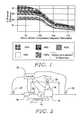
- FIG. 1is an illustrative graph of efficiency data for an example commercial boiler. It can be seen that efficiency may improve as return water temperature drops, while efficiency may drop as the percentage of total output capacity increases. It should be noted that a minimum firing rate is also sometimes needed for stability and safety purposes. Meanwhile, difficulties can arise with return water temperatures at low firing rates, as explained by Pouchak, et al., in U.S. Pat. No. 6,694,927, which is incorporated herein by reference.
- the built-in deadband of a systemcreates a delay between an increase in load and an increase in system capacity. For example, if all boilers are off and a call for heat occurs in a lightly loaded situation, the deadband typically causes the system to wait before turning on a first boiler. By the time the first boiler comes on, however, system temperatures may be relatively far from their setpoints, and the firing rate of the first boiler turned on will quickly ramp up. If the heat load is small, however, the load can be quickly met and the boiler turned off. This cycle is inefficient and may create undesired system temperature variations.
- the present inventionin an illustrative embodiment, includes methods of controlling boilers newly added to the operating set of a multi-boiler system.
- a derivative action controlis used reduce the likelihood of overshoot.
- a newly active boileris held at a low firing rate for a predetermined period of time.
- the predetermined period of timemay be cut short under certain conditions.
- FIG. 1is a graph of efficiency data for an example commercial boiler
- FIG. 2is a schematic diagram of an illustrative high efficiency condensing boiler
- FIG. 3is a schematic diagram of an illustrative boiler system incorporating more than one boiler
- FIGS. 4A-4Bshow a block diagram for an illustrative boiler control system
- FIG. 5is a block diagram for an illustrative firing rate control for a boiler
- FIG. 6shows in block form an illustrative stage control
- FIGS. 7-8show illustrative configurations of system/stage control for a boiler system.
- FIG. 1is a graph of efficiency data for an example commercial high efficiency condensing boiler. It can be seen that as input water temperatures drop, efficiency generally improves. Further, as the firing rate drops, efficiency also improves. Due to exhaust/ventilation needs, however, the boiler may have a minimum firing rate level. For the commercial boiler of FIG. 1 , a minimum firing rate occurs at about 25% of heat output capacity. Reducing blower output, fan speeds, and gas feed below this level can create potential hazards including the poor venting and accumulation of fumes resulting from spent fuel. A minimum firing rate is typically set for the boiler such that there is a minimum heat output for the boiler.
- FIG. 2is a schematic diagram of a high efficiency condensing boiler.
- the systemincludes a pump 12 for moving water through a primary heat exchanger 14 .
- Flue gasses 17 from the primary heat exchanger 14are directed to a secondary heat exchanger 16 placed in the return water path for the system.
- Firing rate and flue gas flowsare controlled using a combustion/purge blower 18 .
- the firing ratemay also be controlled using various valves for controlling fuel flow, fuel/air mixers, etc. (not shown).
- a bypass valve 20is used to direct output water back to the return flow before it enters the primary heat exchanger 14 , as needed, to keep the temperature of fluid entering the primary heat exchanger 14 above a predefined set point.
- Several sensors 22 , 24 , 26may be provided to relay signals to a controller 28 .
- the controller 28may control several system components including the pump 12 , blower 18 , and bypass valve 20 , and other boiler components such as gas valves, ignition controls, fuel/air mixers, etc.
- the combustion/purge blower 18may be a variable frequency drive unit that can provide a variable firing rate for the boiler.
- the variable frequency drive of the blower 18operates at an increased level, the blower 18 increases the heating output of the boiler and forces a greater amount of flue gasses 17 to the secondary heat exchanger 16 .
- the blower 18works in conjunction, typically, with other devices for mixing air and fuel, controlling ventilation, etc.
- the secondary heat exchanger 16typically warms inlet water before it enters the primary heat exchanger 14 by heat exchange with flue gasses 17 . As the flue gasses 17 pass through the secondary heat exchanger 16 , condensate can form inside the secondary heat exchanger 16 .
- the secondary heat exchanger 16is usually designed or adapted to handle condensation without becoming damaged.
- the sensor that senses the fluid temperature prior to the secondary heat exchanger 16may be referred to as the inlet sensor 24 .
- the sensor that senses the fluid temperature of the mix of circulating fluid coming from the secondary heat exchanger 16 and fluid passed back through the bypass valve before it enters the primary heat exchanger 14may be referred to as the bypass sensor 26 .
- the sensor that senses the fluid temperature after the primary heat exchanger 14may be referred to as the output sensor 22 .
- condensationmay occur in the primary heat exchanger 14 .
- Such condensationmay occur when the bypass temperature falls below one-hundred thirty degrees Fahrenheit (fifty-five degrees Celsius), and some times blow around one-hundred twenty degrees Fahrenheit (forty-nine degrees Celsius).
- Such condensation in the primary heat exchangercan, in some cases, damage the primary heat exchanger 14 .
- the bypass valve 20may open to a greater degree to allow heated output water to feed back to the return flow and warm the temperature sensed at the bypass temperature sensor 26 .
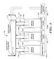
- FIG. 3is a schematic diagram for a boiler system incorporating more than one boiler.
- the illustrative system 100includes a number of modular boilers 102 which may, in terms of the system 100 , be referred to as “stages” of the system 100 .
- each boiler 102includes a boiler control 104 , which is coupled to a corresponding temperature sensor 106 for monitoring fluid temperatures to and from the corresponding boiler 102 .
- the boiler controls 104are connected via a bus (E-bus) to a boiler system controller 108 .
- a pump 110may be provided separate of the internal pumps of the modular boilers 102 to help provide consistent fluid flow regardless of how may of the boiler stages 102 are currently active.
- the boiler system controller 108may also be coupled to and help control the pump 110 , if desired.
- the boiler system controller 108is coupled to a system supply temperature sensor 112 and a system return temperature sensor 114 .
- the outputs of either or both of the sensors 112 , 114may be used by the boiler system controller 108 to determine the present load conditions.
- Various other sensorsmay also be used independently or in conjunction with sensors 112 , 114 .
- the system return temperature sensor 114provides a return temperature signal that can be compared to a desired return temperature set point, and the operation of the system 100 may be adjusted by the boiler system controller 108 to meet the desired return temperature set point.
- the boiler system controller 108sends both enable/disable (or active/inactive) control signals as well as an output capacity or firing rate signal to each of the boiler controllers 104 via the E-bus.
- the boiler system controller 108calls for a selected boiler 102 to be active, the corresponding boiler controller 104 activates the selected boiler 102 .
- the circulating fluidenters the selected boiler 102 , is heated, and is pumped out by the pump 110 . While a parallel configuration is illustrated in FIG. 3 , any of a number of parallel, series, or combination parallel/series boiler configurations may be used and still be within the scope of the present invention.
- FIGS. 4A-4Bshow a block diagram of an illustrative boiler control system.
- the illustrative boiler control systemis divided into two main blocks, a system control block 150 and a stage control block 152 .
- a system sensor block 154provides a sensed temperature to temperature control block 156 , which may be configured to calculate an error signal, which may relate, for example, a proportional and integral derivative error.
- the temperature control blockmay simply look up an error signal via a look-up table or the like.
- the temperature control block 156sends a percent error or demand signal to an analog stage control block 158 and a stager block 160 , as shown.
- the analog stage control block 158generates a percent demand signal that is sent to the stager block 160 as well as a system derivative action block 162 .
- the stager block 160determines how many stages should be called, and determines whether to add or remove stages in response to the error signal.
- the illustrative embodimentalso shows that the stager block 160 may create a signal indicating whether a new stage should be called, and may provide that signal to the system derivative action block 162 .
- the stager block 160only provides this signal if a transition from no active stages to one active stage occurs. If the system derivative action block 162 is enabled, and determines that limited firing rates may be appropriate, the percent control signal received from the analog stage control block 158 may be modified before it is sent to the network interface block 164 . Illustrative methods for making such a determination are further explained below with reference to FIGS. 5 and 6 .
- the system derivative action block 162may generate a signal to reduce the percent control signal received from the analog stage control block 158 to a level that is selected to limit the firing rate of a newly activated stage. In another illustrative configuration, the system derivative action block 162 may not be enabled, and the control signal received from the analog stage control block 158 is passed unchanged to the network interface block 164 .
- a sequencer block 166may identify which stages to call/activate/enable to equalize runtime among the stages.
- the sequencer block 166also may send a signal to the network interface block 164 indicating how many and which stages to activate/enable. If a other settings are desired the sequencer block 166 may enable such settings, for example to identify which stages to activate or de-activate to create first-on/first-off or first-on/last-off sequencing.
- the network interface block 164 of the system block 150may be coupled to a network interface block 168 in each boiler stage 152 .
- the connectionsmay be serial or parallel connections, as desired.
- One illustrative systemmakes use of an Echelon LonworksTM compatible bus, which is a relatively simple two wire bus system.
- the network interface block 168 in boiler stage 152is coupled to a stage on/off network mode block 170 and a modulation rate control block 172 .
- the stage on/off network mode block 170controls whether the boiler stage 152 is on or off.
- the stage on/off network mode block 170also provides a signal to the flame safety control block 174 , which in turn operates and monitors an ignition source 176 and a gas valve 178 .
- the stage on/off network mode block 170may also provide a signal to a stage derivative action block 180 .
- the stage derivative action block 180is disabled and, the system derivative action block 162 of system control block 150 may control stage firing rates by, for example, artificially lowering the analog stage control signal as desired or when needed.
- the derivative action block 180may be enabled. In such cases, signals may be taken from the stage on/off network mode block 170 to determine whether the boiler stage 152 is newly called and, optionally, whether the stage 152 is a first-called stage. If the derivative action block 180 determines that derivative action is proper under the circumstances (again, examples of the decisions made in the derivative action block 180 are explained below with reference to FIGS. 5 and 6 ), then the derivative action block 180 may, for example, check a stage configuration signal to determine whether the timer 186 is enabled, as well as determine the settings for derivative action since these may also be configured by a user.
- the derivative action block 180may also receive signals from a temperature sensor 184 to determine if derivative action block 180 should be disabled due to temperature variations in the circulating/working fluid of the boiler system. Also, the derivative action block 180 may check a timer 186 to determine if the period for action has expired.
- Some example conditions where derivative action is enabledinclude: operation within a set time period after a first stage is added along with operation while temperatures of the circulating/working fluid of the boiler system are not dropping quickly. If the conditions for action are all met, then the derivative action block 180 may send a signal to logic block 188 indicating that the firing rate should remain low. This signal is used to override the signal sent to logic block 188 from modulation rate control block 172 to provide a desired heat output level or firing rate.
- the boiler stage 152may further include a bypass control system 190 that provides one or more signals to both a cold water draw block 192 and the stage on/off network mode block 170 .
- the bypass control system 190is further illustrated in FIG. 4B , which is further described below.
- the stage on/off network mode block 170may disable the derivative action block 180 if commanded by the bypass control system 190 .
- the bypass control system 190may signal to logic block 188 , via the cold water draw block 192 , that the derivative action block 180 may be overridden.
- Logic block 188makes the determination of what the variable firing rate demand 194 should be to control the firing rate of the stage 152 .
- a first source for the logic block 188may be the modulation rate control block 172 , which provides a heat load signal related to the load signal generated by the analog stage control 158 as modified (potentially) by the system derivative action 162 .
- the signal from block 172may be overridden or modified by either the bypass control system 190 or the derivative action block 180 , when enabled.
- the bypass control system 190receives highest priority because it is responsible for protecting the boiler or stage 152 from damage caused by, for example, condensation in the primary heat exchanger.
- FIG. 4Bshows several features of an illustrative bypass temperature control block 190 .
- a sensed bypass temperature 200is compared to a set point (not shown) and/or sent to a lookup table 202 (this may include calculating a rate or integral error on the bypass temperature 200 , if desired), and the resulting signal or signals are sent to a bypass temperature control block 204 which is adapted to determine the desired position of the bypass valve 208 .
- the bypass temperature control 204receives configuration settings 206 that may include the current position of the bypass valve 208 , system operation history analysis, system settings, user preferences, and/or any other settings, parameters and/or characteristics, as desired.
- the bypass temperature control 204may send a signal to change the position of the bypass valve 208 .
- the signal for changing the position of the bypass valve 208may also be received and recorded by a position accumulator 210 .
- the position accumulator 210may provide a signal that indicates a current position of the bypass valve 208 .
- the position accumulator 210may indicate that the bypass valve 208 is open by a certain percentage, or by some other scale as desired.
- bypass temperature control 204may call for the bypass valve 208 to partly or fully close.
- the bypass temperature control 204may call for opening the bypass valve 208 further from its current position. If the bypass valve 208 is already fully open, the bypass temperature control 204 may call for an increase in the stage firing rate to increase the temperature of the water that is fed back to the water return.
- the bypass temperature controlmay include or operate in parallel with an inlet temperature sensor.
- the firing ratemay be raised right away, rather than waiting for the bypass valve to open completely.
- the call for increased firing ratemay override a derivative action call for reduced firing rate.
- FIG. 5is a flow diagram showing an illustrative method for performing firing rate control for a boiler that is adapted to limit the firing rate of the boiler during a time period after a stage is first activated.
- the control methodis illustrated as a number of steps, and may be implemented in several ways by allocating control steps to different parts of a boiler system including a system controller and/or a stage controller. Two illustrative allocations of control using both a system controller and a stage controller are illustrated in FIGS. 7-8 .
- the method shown in FIG. 5is repetitively executed at a predetermined interval, each time beginning at start block 250 .
- the predetermined intervalmay vary as desired.
- the predetermined intervalis chosen to be shorter than a staging/modulation control interval at which overall staging and modulation are calculated and performed.
- the predetermined intervalmay be about five seconds, while the interval for the overall staging/modulation control may be about fifteen seconds.
- the overall stagingmay have a first interval
- modulationmay have a second interval
- the firing rate controlmay have a third interval shorter than the first and/or second intervals.
- the first intervalis about fifteen seconds
- the second intervalis about five seconds
- the third intervalis about five seconds or less.
- Other valuesmay be used, as desired. As the intervals decrease in time, the system accuracy may increase, however, efficiency may be reduced due to accelerated cycling.
- controlis passed to block 260 , which determines if the system is transitioning from no active stages to one active stage. If so, control is passed to block 262 , which sets a timer to a timer setpoint.
- the timer setpointmay represent a delay that must occur before the firing rate may be increased for a newly activated first stage. In one embodiment, the timer setpoint may be set to about two minutes, while greater and lesser values may be used as desired.
- the methodcontinues by setting the error as the difference between a desired set point and a measured temperature value.
- the measured temperature valuecorrespond to the system return temperature or the system supply temperature (e.g. sensors 114 , 112 , respectively, in FIG. 3 ).
- the methodchecks to see whether the timer is less than or equal to zero, as shown at 266 . If the timer is not less than or equal to zero, the timer has not yet expired, and control is passed to block 262 . If the timer is less than or equal to zero, the timer is set to zero as shown at 268 (avoiding possible overflow errors), and control is passed to block 254 where the normal firing rate is used as shown at 254 , and control is passed to end block 256 .
- the methoddetermines whether the stage is a standalone boiler as shown at 276 (i.e. whether the system is not a multi-boiler or multi-stage system). If the stage is a stand alone boiler, the firing rate is set to a minimum value at block 278 . In some cases, the minimum value may correspond to a minimum firing rate for the boiler. Several commercial boilers have a minimum firing rate of about 25% of their maximum firing rate, but other minimum values may also be used.
- the other stagesare set to off because at decision block 260 , it was determined that the system is transitioning from no active stages to one active stage.
- the timeris decremented as shown at block 282 . Then, the method comes to end block at shown at 256 and waits for the beginning of the next interval.
- the various stepsmay be performed by controllers, sensors, and/or logic at either a system control level or a stage control level, or a combination thereof, as desired.
- FIGS. 7 and 8illustrate two example configurations.
- FIG. 6shows in block form an illustrative stage control method for disabling derivative control.
- the method 300begins with an error calculation 302 which takes the output of a temperature sensor 304 and compares it to a desired set point 306 .
- An old measured value 308is also read in.
- the erroris set to the difference between the set point 306 and the measured value, and a rate value is set as the difference between the measured value and the old measured value 308 , as shown at 302 .
- a comparison step 310comes next.
- the derivative actionis disabled as shown at 312 . If the output of the comparison step 310 is a “no”, or after the disable step 312 , control is passed to the derivative action block 314 .
- the derivative action block 314receives signals from a stager on/off block 316 and a timer 318 .
- the stager on/off block 316provides a signal indicating if derivative action 314 is otherwise appropriate, such as if the current stage is being activated and, in one embodiment, if the current stage is the first stage activated.
- the timer 318is used by the derivative action 314 to determine how long derivative action should continue. Using these signals to indicate whether derivative action is enabled, appropriate, and should continue, the derivative action block 314 sends a signal to logic 320 .
- logic 320receives signals from each of the derivative action block 314 , cold water draw control 322 , and modulation control 324 , and uses these signals to determine a firing rate demand to send to the VFD 326 .
- the cold water draw logic 322may generate a call for increased firing rate to avoid condensation in a boiler.
- the modulation control 324may be controlled in various ways. Some illustrative modulation control methods are shown in copending U.S. patent application Ser. No. 10/809,115 entitled MULTI-STAGE BOILER CONTROL STAGING AND MODULATION METHODS AND CONTROLLERS, published as US 2005-0230490 A1, which is incorporated herein by reference.
- FIGS. 7-8illustrate configurations for system and stage control for a multi-stage boiler system.
- the system controller 350 and stage controller 352interact in several illustrative fashions. Commands, status and information are exchanged between system configuration 354 and stage configuration 356 .
- the example shownillustrates that the system controller 352 may send a stage command to the stage controller 352 indicating whether a boiler stage should be on or off.
- the system controller 350may send a stage modulation signal that is used in the stage controller 352 by firing rate control logic to control the firing rate of the stage.
- the stage controller 352may send status indications to a status memory in the system controller 350 .
- the system controller 350 and stage controller 352are configured to allocate derivative action control to the level of the system controller 350 .
- the system controller 350is configured with derivative action control to keep the heat demand signal relatively low for a predefined time period, with certain exceptions, as shown at 358 .
- Some illustrative exceptionsincluding: a continuing drop in circulating fluid temperatures after a boiler stage is activated; whether or not a stage newly activated is the first stage activated; and user overrides.
- system controller 350may receive calls for heat from multiple sensors, certain calls may be of a type indicating that derivative action control is either not needed or undesirable.
- a systemmay receive a call for heat from a small area (single office heat) and a large area (gymnasium heat). The system may elect to use derivative action only when the small area calls for heat.
- stage controller 352may be optionally configured with a cold water bypass control override as shown at 360 , and may not have a derivative action block enabled, though such functionality may be programmed (or hardwired, as desired) into the stage controller 352 .
- the configuration of FIG. 8operates differently.
- the system controller 370while having a set of stage and status commands and memory shown at 374 , interacts with the stage controller 372 , also having certain command receiving and status indicators.
- the system controller 370simply indicates whether the stage controller 372 is the first stage activated or not, as shown at 378 .
- the stage controller 372as shown at 380 , has the derivative action control which is enabled if the stage is the first stage called, and in the illustrative embodiment, also retains the optional cold water bypass control override.
- the controllers 350 , 352 , 370 , 372may be readily adjusted for either configuration. When so provided, this may allow the individual components to be used with a variety of systems.
- the system controller 350may be operated in conjunction with a boiler/stage controller lacking the derivative action control. In some cases, this may allow the system controller 350 to be provided as a retrofit controller onto an existing system.
Landscapes
- Engineering & Computer Science (AREA)
- Chemical & Material Sciences (AREA)
- Combustion & Propulsion (AREA)
- Mechanical Engineering (AREA)
- General Engineering & Computer Science (AREA)
- Physics & Mathematics (AREA)
- Thermal Sciences (AREA)
- Control Of Steam Boilers And Waste-Gas Boilers (AREA)
Abstract
Description
Claims (10)
Priority Applications (1)
| Application Number | Priority Date | Filing Date | Title |
|---|---|---|---|
| US10/826,416US8251297B2 (en) | 2004-04-16 | 2004-04-16 | Multi-stage boiler system control methods and devices |
Applications Claiming Priority (1)
| Application Number | Priority Date | Filing Date | Title |
|---|---|---|---|
| US10/826,416US8251297B2 (en) | 2004-04-16 | 2004-04-16 | Multi-stage boiler system control methods and devices |
Publications (2)
| Publication Number | Publication Date |
|---|---|
| US20050230491A1 US20050230491A1 (en) | 2005-10-20 |
| US8251297B2true US8251297B2 (en) | 2012-08-28 |
Family
ID=35095280
Family Applications (1)
| Application Number | Title | Priority Date | Filing Date |
|---|---|---|---|
| US10/826,416Expired - Fee RelatedUS8251297B2 (en) | 2004-04-16 | 2004-04-16 | Multi-stage boiler system control methods and devices |
Country Status (1)
| Country | Link |
|---|---|
| US (1) | US8251297B2 (en) |
Cited By (7)
| Publication number | Priority date | Publication date | Assignee | Title |
|---|---|---|---|---|
| US20100276502A1 (en)* | 2006-02-17 | 2010-11-04 | Heat Energy & Associated Technology Limited | Method And Apparatus For Commissioning And Balancing A Wet Central Heating System |
| US20120160472A1 (en)* | 2010-10-21 | 2012-06-28 | Kim Si-Hwan | Method for controlling a parallel operation of a multi-water heater |
| CN105465822A (en)* | 2015-12-09 | 2016-04-06 | 深圳粤通新能源环保技术有限公司 | Boiler automatic control system and method |
| US20160187029A1 (en)* | 2014-12-25 | 2016-06-30 | Rinnai Corporation | Connected hot-water supply system |
| US20170299200A1 (en)* | 2016-04-13 | 2017-10-19 | Paul D Mercier, SR. | Enhanced convection, differential temperature managed, hydronic heating appliance |
| US9927190B2 (en)* | 2012-01-12 | 2018-03-27 | Lacon Systems Ltd. | Method of controlling a chiller |
| US20230204225A1 (en)* | 2015-11-06 | 2023-06-29 | Mestek, Inc. | Networked boiler system |
Families Citing this family (7)
| Publication number | Priority date | Publication date | Assignee | Title |
|---|---|---|---|---|
| US7506617B2 (en)* | 2007-03-09 | 2009-03-24 | Lochinvar Corporation | Control system for modulating water heater |
| US8141623B2 (en)* | 2007-05-01 | 2012-03-27 | Blecker Joseph G | Automatic switching two pipe hydronic system |
| US8479689B2 (en)* | 2008-07-10 | 2013-07-09 | Heat-Timer Corporation | Optimizing multiple boiler plant systems with mixed condensing and non-condensing boilers |
| JP5228700B2 (en)* | 2008-08-25 | 2013-07-03 | 三浦工業株式会社 | Control program, control device and boiler system |
| US10101048B2 (en)* | 2013-03-15 | 2018-10-16 | Honeywell International Inc. | Supervisory controller for HVAC systems |
| CN107289632B (en)* | 2016-11-11 | 2020-02-04 | 广东美的暖通设备有限公司 | Intelligent water return control method, controller and control system |
| CA3107299A1 (en) | 2020-01-31 | 2021-07-31 | Rinnai America Corporation | Vent attachment for a tankless water heater |
Citations (37)
| Publication number | Priority date | Publication date | Assignee | Title |
|---|---|---|---|---|
| US3162430A (en)* | 1961-12-29 | 1964-12-22 | Hupp Corp | Oven control |
| US3362637A (en)* | 1964-12-03 | 1968-01-09 | Brunswick Corp | Car heater system |
| US3865306A (en)* | 1971-08-13 | 1975-02-11 | Eberspaecher J | Means for controlling the course of operation of an auxiliary heating system in motor vehicles or ships |
| US3997109A (en)* | 1974-01-24 | 1976-12-14 | Amana Refrigeration, Inc. | Heat exchange control system |
| US4373663A (en) | 1981-12-10 | 1983-02-15 | Honeywell Inc. | Condition control system for efficient transfer of energy to and from a working fluid |
| US4513910A (en) | 1984-09-17 | 1985-04-30 | Honeywell Inc. | Adaptive low fire hold control system |
| US4519540A (en)* | 1981-08-27 | 1985-05-28 | Societe Anonyme Saunier Duval Eau Chaude Chauffage - S.D.E.C.C. | Sealed gas heater with forced draft and regulation by microprocessor |
| US4638767A (en)* | 1984-07-03 | 1987-01-27 | Stone Allen Limited | Heating system |
| US4716858A (en)* | 1986-12-18 | 1988-01-05 | Honeywell Inc. | Automatic firing rate control mode means for a boiler |
| US4787554A (en)* | 1988-02-01 | 1988-11-29 | Honeywell Inc. | Firing rate control system for a fuel burner |
| US4841918A (en)* | 1986-11-06 | 1989-06-27 | Babcock-Hitachi Kabushiki Kaisha | Boiler control system |
| EP0325356A2 (en) | 1988-01-21 | 1989-07-26 | Honeywell Inc. | Multiple fuel burner control system |
| US4930488A (en)* | 1988-08-18 | 1990-06-05 | Gas Research Institute | Processor-controlled gas appliances and microprocessor-actuated valves for use therein |
| US4931948A (en)* | 1987-02-12 | 1990-06-05 | Parker Electronics, Inc. | Method and system for controlling a single zone HVAC supplying multiple zones |
| US5016577A (en)* | 1990-04-17 | 1991-05-21 | Hunt Thomas C | Heat exchanger |
| US5042431A (en)* | 1990-04-09 | 1991-08-27 | Heat Timer Corporation | Multiple boiler control system and method of operation |
| US5053978A (en)* | 1989-05-26 | 1991-10-01 | Jeffrey Solomon | Automatic boiler room equipment monitoring system |
| US5172654A (en) | 1992-02-10 | 1992-12-22 | Century Controls, Inc. | Microprocessor-based boiler controller |
| EP0614047A1 (en) | 1993-03-05 | 1994-09-07 | Landis & Gyr Technology Innovation AG | Electronic control device for gas burners of heating installations |
| US5350114A (en)* | 1993-07-21 | 1994-09-27 | The Budd Company | Microprocessor controller for diesel fuel fired heater |
| US5452687A (en)* | 1994-05-23 | 1995-09-26 | Century Controls, Inc. | Microprocessor-based boiler sequencer |
| US5667374A (en)* | 1992-10-16 | 1997-09-16 | Process Combustion Corporation | Premix single stage low NOx burner |
| US5713515A (en) | 1995-12-05 | 1998-02-03 | Pvi Industries, Inc. | Method and system in a fluid heating apparatus for efficiently controlling combustion |
| US5971745A (en)* | 1995-11-13 | 1999-10-26 | Gas Research Institute | Flame ionization control apparatus and method |
| US6021752A (en)* | 1995-09-12 | 2000-02-08 | J. Eberspacher Gmbh & Co. | Vehicle heater independent of the engine |
| US6062485A (en)* | 1998-04-22 | 2000-05-16 | Erie Manufacturing Company | Radiant heating system reset control |
| US6089855A (en)* | 1998-07-10 | 2000-07-18 | Thermo Power Corporation | Low NOx multistage combustor |
| US6109339A (en)* | 1996-07-15 | 2000-08-29 | First Company, Inc. | Heating system |
| WO2001094847A2 (en) | 2000-06-08 | 2001-12-13 | Honeywell International Inc. | Distributed appliance control system having fault isolation |
| US20020193890A1 (en) | 2000-12-15 | 2002-12-19 | Pouchak Michael A. | Fault-tolerant multi-node stage sequencer and method for energy systems |
| US6536678B2 (en) | 2000-12-15 | 2003-03-25 | Honeywell International Inc. | Boiler control system and method |
| US6540148B1 (en)* | 2001-07-27 | 2003-04-01 | Johnson Controls Technology Company | Method and apparatus for sequencing multistage systems of known relative capacities |
| US6598397B2 (en)* | 2001-08-10 | 2003-07-29 | Energetix Micropower Limited | Integrated micro combined heat and power system |
| US6647302B2 (en)* | 2000-12-15 | 2003-11-11 | Honeywell International Inc. | Human interface panel for boiler control system |
| US6694927B1 (en)* | 2003-02-18 | 2004-02-24 | Honeywell International Inc. | Cold water draw bypass valve and variable firing boiler control |
| US6904874B1 (en)* | 2004-03-25 | 2005-06-14 | Honeywell International Inc. | Forward calculation energy augmentation method |
| US7819334B2 (en)* | 2004-03-25 | 2010-10-26 | Honeywell International Inc. | Multi-stage boiler staging and modulation control methods and controllers |
- 2004
- 2004-04-16USUS10/826,416patent/US8251297B2/ennot_activeExpired - Fee Related
Patent Citations (38)
| Publication number | Priority date | Publication date | Assignee | Title |
|---|---|---|---|---|
| US3162430A (en)* | 1961-12-29 | 1964-12-22 | Hupp Corp | Oven control |
| US3362637A (en)* | 1964-12-03 | 1968-01-09 | Brunswick Corp | Car heater system |
| US3865306A (en)* | 1971-08-13 | 1975-02-11 | Eberspaecher J | Means for controlling the course of operation of an auxiliary heating system in motor vehicles or ships |
| US3997109A (en)* | 1974-01-24 | 1976-12-14 | Amana Refrigeration, Inc. | Heat exchange control system |
| US4519540A (en)* | 1981-08-27 | 1985-05-28 | Societe Anonyme Saunier Duval Eau Chaude Chauffage - S.D.E.C.C. | Sealed gas heater with forced draft and regulation by microprocessor |
| US4373663A (en) | 1981-12-10 | 1983-02-15 | Honeywell Inc. | Condition control system for efficient transfer of energy to and from a working fluid |
| US4638767A (en)* | 1984-07-03 | 1987-01-27 | Stone Allen Limited | Heating system |
| US4513910A (en) | 1984-09-17 | 1985-04-30 | Honeywell Inc. | Adaptive low fire hold control system |
| US4841918A (en)* | 1986-11-06 | 1989-06-27 | Babcock-Hitachi Kabushiki Kaisha | Boiler control system |
| US4716858A (en)* | 1986-12-18 | 1988-01-05 | Honeywell Inc. | Automatic firing rate control mode means for a boiler |
| US4931948A (en)* | 1987-02-12 | 1990-06-05 | Parker Electronics, Inc. | Method and system for controlling a single zone HVAC supplying multiple zones |
| EP0325356A2 (en) | 1988-01-21 | 1989-07-26 | Honeywell Inc. | Multiple fuel burner control system |
| US4787554A (en)* | 1988-02-01 | 1988-11-29 | Honeywell Inc. | Firing rate control system for a fuel burner |
| US4930488A (en)* | 1988-08-18 | 1990-06-05 | Gas Research Institute | Processor-controlled gas appliances and microprocessor-actuated valves for use therein |
| US5053978A (en)* | 1989-05-26 | 1991-10-01 | Jeffrey Solomon | Automatic boiler room equipment monitoring system |
| US5042431A (en)* | 1990-04-09 | 1991-08-27 | Heat Timer Corporation | Multiple boiler control system and method of operation |
| US5016577A (en)* | 1990-04-17 | 1991-05-21 | Hunt Thomas C | Heat exchanger |
| US5172654A (en) | 1992-02-10 | 1992-12-22 | Century Controls, Inc. | Microprocessor-based boiler controller |
| US5667374A (en)* | 1992-10-16 | 1997-09-16 | Process Combustion Corporation | Premix single stage low NOx burner |
| EP0614047A1 (en) | 1993-03-05 | 1994-09-07 | Landis & Gyr Technology Innovation AG | Electronic control device for gas burners of heating installations |
| US5350114A (en)* | 1993-07-21 | 1994-09-27 | The Budd Company | Microprocessor controller for diesel fuel fired heater |
| US5452687A (en)* | 1994-05-23 | 1995-09-26 | Century Controls, Inc. | Microprocessor-based boiler sequencer |
| US6021752A (en)* | 1995-09-12 | 2000-02-08 | J. Eberspacher Gmbh & Co. | Vehicle heater independent of the engine |
| US5971745A (en)* | 1995-11-13 | 1999-10-26 | Gas Research Institute | Flame ionization control apparatus and method |
| US5713515A (en) | 1995-12-05 | 1998-02-03 | Pvi Industries, Inc. | Method and system in a fluid heating apparatus for efficiently controlling combustion |
| US6109339A (en)* | 1996-07-15 | 2000-08-29 | First Company, Inc. | Heating system |
| US6062485A (en)* | 1998-04-22 | 2000-05-16 | Erie Manufacturing Company | Radiant heating system reset control |
| US6089855A (en)* | 1998-07-10 | 2000-07-18 | Thermo Power Corporation | Low NOx multistage combustor |
| WO2001094847A2 (en) | 2000-06-08 | 2001-12-13 | Honeywell International Inc. | Distributed appliance control system having fault isolation |
| US20020193890A1 (en) | 2000-12-15 | 2002-12-19 | Pouchak Michael A. | Fault-tolerant multi-node stage sequencer and method for energy systems |
| US6536678B2 (en) | 2000-12-15 | 2003-03-25 | Honeywell International Inc. | Boiler control system and method |
| US6647302B2 (en)* | 2000-12-15 | 2003-11-11 | Honeywell International Inc. | Human interface panel for boiler control system |
| US6745085B2 (en)* | 2000-12-15 | 2004-06-01 | Honeywell International Inc. | Fault-tolerant multi-node stage sequencer and method for energy systems |
| US6540148B1 (en)* | 2001-07-27 | 2003-04-01 | Johnson Controls Technology Company | Method and apparatus for sequencing multistage systems of known relative capacities |
| US6598397B2 (en)* | 2001-08-10 | 2003-07-29 | Energetix Micropower Limited | Integrated micro combined heat and power system |
| US6694927B1 (en)* | 2003-02-18 | 2004-02-24 | Honeywell International Inc. | Cold water draw bypass valve and variable firing boiler control |
| US6904874B1 (en)* | 2004-03-25 | 2005-06-14 | Honeywell International Inc. | Forward calculation energy augmentation method |
| US7819334B2 (en)* | 2004-03-25 | 2010-10-26 | Honeywell International Inc. | Multi-stage boiler staging and modulation control methods and controllers |
Non-Patent Citations (9)
| Title |
|---|
| Ashrae Applications Handbook, "Service Water Heating", pp. 48.21-48.22, 1999. |
| Ashrae Systems and Equipment Handbook, "Boilers", Chapter 27, pp. 27.1-27.6, 1996. |
| Engineering Manual of Automatic Control, "Chiller, Boiler, and Distribution System Control Applications", pp. 332-335, prior to filed of current application. |
| ES Engineered Systems, "Features Item: A New Look At Modular Boiler Systems," 10 pages, Mar. 2001. |
| Lochinvar Corporation, "LonWorks System Integrator Guide for the Intelli-Fin Boiler Interface Controller", Version LOCH SIG-01, pp. 1-59, Jun. 2001. |
| Lochinvar, "Intelli-Fin Gas Fired Boilers," 6 pages, Apr. 2003. |
| Lochinvar, "Intelli-Fin Sequencing Options Mean New Levels of Building Efficiency," 2 pages, Nov. 2002. |
| Slant Fin Terra Thelma, Typical Applications, 15 pages, Feb. 2002. |
| Triad Boiler Systems Inc., "Modular Steel Firetube Packaged Boiler Systems," 3 pages, Mar. 12, 2004. |
Cited By (10)
| Publication number | Priority date | Publication date | Assignee | Title |
|---|---|---|---|---|
| US20100276502A1 (en)* | 2006-02-17 | 2010-11-04 | Heat Energy & Associated Technology Limited | Method And Apparatus For Commissioning And Balancing A Wet Central Heating System |
| US20120160472A1 (en)* | 2010-10-21 | 2012-06-28 | Kim Si-Hwan | Method for controlling a parallel operation of a multi-water heater |
| US9513018B2 (en)* | 2010-10-21 | 2016-12-06 | Kyungdong One Corporation | Method for controlling a parallel operation of a multi-water heater |
| US9927190B2 (en)* | 2012-01-12 | 2018-03-27 | Lacon Systems Ltd. | Method of controlling a chiller |
| US20160187029A1 (en)* | 2014-12-25 | 2016-06-30 | Rinnai Corporation | Connected hot-water supply system |
| US10107521B2 (en)* | 2014-12-25 | 2018-10-23 | Rinnai Corporation | Connected hot-water supply system |
| US20230204225A1 (en)* | 2015-11-06 | 2023-06-29 | Mestek, Inc. | Networked boiler system |
| CN105465822A (en)* | 2015-12-09 | 2016-04-06 | 深圳粤通新能源环保技术有限公司 | Boiler automatic control system and method |
| US20170299200A1 (en)* | 2016-04-13 | 2017-10-19 | Paul D Mercier, SR. | Enhanced convection, differential temperature managed, hydronic heating appliance |
| US10690356B2 (en)* | 2016-04-13 | 2020-06-23 | Paul D Mercier, SR. | Enhanced convection, differential temperature managed, hydronic heating appliance |
Also Published As
| Publication number | Publication date |
|---|---|
| US20050230491A1 (en) | 2005-10-20 |
Similar Documents
| Publication | Publication Date | Title |
|---|---|---|
| US7819334B2 (en) | Multi-stage boiler staging and modulation control methods and controllers | |
| US8251297B2 (en) | Multi-stage boiler system control methods and devices | |
| CA2671149C (en) | Optimizing multiple boiler plant systems with mixed condensing and non-condensing boilers | |
| US7644869B2 (en) | Auxiliary stage control of multistage thermostats | |
| US6729390B1 (en) | Control for heat pump with auxiliary heat source | |
| US8204628B2 (en) | Setpoint recovery with utility time of day pricing | |
| US6694927B1 (en) | Cold water draw bypass valve and variable firing boiler control | |
| KR101436071B1 (en) | Individual heating system and method for controlling the same | |
| Taylor | Increasing efficiency with VAV system static pressure setpoint reset | |
| KR100660565B1 (en) | Condensing Boiler and its Control Method | |
| JP5515166B2 (en) | Heat source system | |
| EP0684426B1 (en) | Microprocessor-based boiler sequencer | |
| JP5227247B2 (en) | Heat source system operating method and heat source system | |
| KR101961565B1 (en) | Optimal operation of heating cascade system operation control method | |
| KR101749125B1 (en) | heating water suppling system and controlling method thereof | |
| EP3525060B1 (en) | Flow control module and method for controlling the flow in a hydronic system | |
| KR100633593B1 (en) | Boiler interlocking temperature control system and heating water return pipe for boiler used in the system | |
| EP2122261B1 (en) | Boiler for a heating system, in particular for domestic use | |
| KR101476645B1 (en) | Method for controlling heating temperature for each room in the heating system for each room | |
| JP2011247487A (en) | Water heater | |
| CN114322252B (en) | Combined air conditioning unit and control method thereof | |
| JP3865861B2 (en) | Automatic control method for air conditioning equipment | |
| KR101007514B1 (en) | Heating distributor and heating control method, and the heating water distributor used to control the heating | |
| JP2008121970A (en) | Multi-type air conditioner | |
| JP7500143B2 (en) | Control device, control method and program for heat source device in air conditioning system |
Legal Events
| Date | Code | Title | Description |
|---|---|---|---|
| AS | Assignment | Owner name:HONEYWELL INTERNATIONAL INC., NEW JERSEY Free format text:ASSIGNMENT OF ASSIGNORS INTEREST;ASSIGNORS:POUCHAK, MICHAEL A.;HAMMER, JEFFREY M.;REEL/FRAME:015230/0884;SIGNING DATES FROM 20040408 TO 20040415 Owner name:HONEYWELL INTERNATIONAL INC., NEW JERSEY Free format text:ASSIGNMENT OF ASSIGNORS INTEREST;ASSIGNORS:POUCHAK, MICHAEL A.;HAMMER, JEFFREY M.;SIGNING DATES FROM 20040408 TO 20040415;REEL/FRAME:015230/0884 | |
| ZAAA | Notice of allowance and fees due | Free format text:ORIGINAL CODE: NOA | |
| ZAAB | Notice of allowance mailed | Free format text:ORIGINAL CODE: MN/=. | |
| STCF | Information on status: patent grant | Free format text:PATENTED CASE | |
| FPAY | Fee payment | Year of fee payment:4 | |
| MAFP | Maintenance fee payment | Free format text:PAYMENT OF MAINTENANCE FEE, 8TH YEAR, LARGE ENTITY (ORIGINAL EVENT CODE: M1552); ENTITY STATUS OF PATENT OWNER: LARGE ENTITY Year of fee payment:8 | |
| FEPP | Fee payment procedure | Free format text:MAINTENANCE FEE REMINDER MAILED (ORIGINAL EVENT CODE: REM.); ENTITY STATUS OF PATENT OWNER: LARGE ENTITY | |
| LAPS | Lapse for failure to pay maintenance fees | Free format text:PATENT EXPIRED FOR FAILURE TO PAY MAINTENANCE FEES (ORIGINAL EVENT CODE: EXP.); ENTITY STATUS OF PATENT OWNER: LARGE ENTITY | |
| STCH | Information on status: patent discontinuation | Free format text:PATENT EXPIRED DUE TO NONPAYMENT OF MAINTENANCE FEES UNDER 37 CFR 1.362 | |
| FP | Lapsed due to failure to pay maintenance fee | Effective date:20240828 |