US8249298B2 - Ultrasonic camera tracking system and associated methods - Google Patents
Ultrasonic camera tracking system and associated methodsDownload PDFInfo
- Publication number
- US8249298B2 US8249298B2US11/872,303US87230307AUS8249298B2US 8249298 B2US8249298 B2US 8249298B2US 87230307 AUS87230307 AUS 87230307AUS 8249298 B2US8249298 B2US 8249298B2
- Authority
- US
- United States
- Prior art keywords
- ultrasound
- camera
- source
- signals
- receivers
- Prior art date
- Legal status (The legal status is an assumption and is not a legal conclusion. Google has not performed a legal analysis and makes no representation as to the accuracy of the status listed.)
- Active, expires
Links
Images


Classifications
- G—PHYSICS
- G01—MEASURING; TESTING
- G01S—RADIO DIRECTION-FINDING; RADIO NAVIGATION; DETERMINING DISTANCE OR VELOCITY BY USE OF RADIO WAVES; LOCATING OR PRESENCE-DETECTING BY USE OF THE REFLECTION OR RERADIATION OF RADIO WAVES; ANALOGOUS ARRANGEMENTS USING OTHER WAVES
- G01S5/00—Position-fixing by co-ordinating two or more direction or position line determinations; Position-fixing by co-ordinating two or more distance determinations
- G01S5/18—Position-fixing by co-ordinating two or more direction or position line determinations; Position-fixing by co-ordinating two or more distance determinations using ultrasonic, sonic, or infrasonic waves
- G01S5/22—Position of source determined by co-ordinating a plurality of position lines defined by path-difference measurements
- G—PHYSICS
- G01—MEASURING; TESTING
- G01S—RADIO DIRECTION-FINDING; RADIO NAVIGATION; DETERMINING DISTANCE OR VELOCITY BY USE OF RADIO WAVES; LOCATING OR PRESENCE-DETECTING BY USE OF THE REFLECTION OR RERADIATION OF RADIO WAVES; ANALOGOUS ARRANGEMENTS USING OTHER WAVES
- G01S3/00—Direction-finders for determining the direction from which infrasonic, sonic, ultrasonic, or electromagnetic waves, or particle emission, not having a directional significance, are being received
- G01S3/80—Direction-finders for determining the direction from which infrasonic, sonic, ultrasonic, or electromagnetic waves, or particle emission, not having a directional significance, are being received using ultrasonic, sonic or infrasonic waves
- G01S3/802—Systems for determining direction or deviation from predetermined direction
- G01S3/808—Systems for determining direction or deviation from predetermined direction using transducers spaced apart and measuring phase or time difference between signals therefrom, i.e. path-difference systems
- H—ELECTRICITY
- H04—ELECTRIC COMMUNICATION TECHNIQUE
- H04N—PICTORIAL COMMUNICATION, e.g. TELEVISION
- H04N7/00—Television systems
- H04N7/14—Systems for two-way working
- H04N7/15—Conference systems
Definitions
- Presenterstypically use hand-held remotes to control a camera of a videoconferencing system.
- a goal for videoconferencingis to produce a natural experience for participants. Therefore, it is not desirable to require the presenter or other participants to spend a great deal of time controlling the camera and handling complex input devices.
- U.S. Pat. No. 6,980,485 assigned to Polycom, Inc.discloses an automatic camera tracking technique that uses beamforming.
- Polycomoffers a voice tracking system called Automatic Camera Positioning or ACP for its VSX videoconferencing system.
- ACPAutomatic Camera Positioning
- Another prior art systemuses color code-based tracking and vision analysis to track a target with a camera.
- the cameramay point to a wall or a table from time to time due to reflection or other causes.
- the cameramay not be able to track someone while moving if that person is not speaking.
- these prior art techniquerun into problems in situations where there are multiple voices or different color codes.
- the subject matter of the present disclosureis directed to overcoming, or at least reducing the effects of, one or more of the problems set forth above.
- a camera tracking systemincludes a controllable camera, an array of microphones, and a controller.
- the microphonesare positioned adjacent the controllable camera and are at least responsive to ultrasound emitted from a source.
- the microphonesmay additionally be capable of responding to sound in an audible spectrum.
- the controllerreceives ultrasound signals communicated from the microphones in response to ultrasound emitted from the source and processes the ultrasound signals to determine an at least approximate location of the source. Then, the controller sends one or more command signals to the controllable camera to direct it at least approximately at the determined location of the source.
- the camera tracking systemtracks the source as it moves and continues to emit ultrasound.
- the sourcecan be an emitter pack worn by a person.
- the emitter packcan have one or more ultrasound transducers that produce an ultrasound tone that sweeps form about 24-kHz to about 40-kHz.
- FIG. 1illustrates one embodiment of a camera tracking system according to certain teachings of the present disclosure.
- FIG. 2illustrates one embodiment of a software framework for a control unit of the camera tracking system of FIG. 1 .
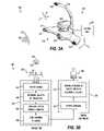
- FIG. 3Aillustrates one embodiment of a camera unit for a camera tracking system.
- FIG. 3Billustrates one embodiment of a signal chain for the camera tracking system of FIG. 3A .
- FIG. 4Aillustrates one embodiment of a down-sampling process to reduce ultrasonic signals to an audible range for the disclosed camera tracking system.
- FIG. 4Billustrate graphs of signal spectra during stages of the down-sampling process of FIG. 4A .
- FIGS. 5A-5Billustrate one embodiment of a position determination algorithm to estimate a candidate location of a targeted source for the disclosed camera tracking system.
- FIGS. 6A-6Billustrate other embodiments of camera tracking systems.
- FIGS. 7A-7Billustrate alternative embodiments of emitter units for the disclosed camera tracking systems.
- the camera tracking system 100includes a camera unit 120 , a control unit 130 , and an emitter unit 140 .
- a presenterwears or carries the emitter unit 140 that acts as a beacon so that the camera unit 120 can follow the presenter by detecting the emitted beacon signal.
- the camera tracking system 100can be used with a remote control 150 and can be used with an external device 160 , such as a videoconferencing system or other system.
- the camera unit 120 and the control unit 130can be separate components as shown, or they can be integrated into one unit.
- the external device 160is shown as a separate component, either one or both of the camera unit 120 and control unit 130 can be integrated with the external device 160 .
- control unit 130controls camera tracking and other features of the system 100 .
- the control unit 130includes a processor (not shown) for performing necessary calculations to perform the camera tracking techniques disclosed herein.
- the processorcan be any device that can make the necessary calculations such as a Central Processing Unit (CPU), Field Programmable Gated Array (FPGA), and the like.
- the control unit 130can receive standard NTSC, PAL s-video or other type of video sent from the camera unit 120 via a first connection 110 .
- the control unit 130also receives a plurality of channels (e.g., four) of line level audio from the camera unit 120 via the connection 110 .
- the control unit 130can communicate controls for the camera unit 120 .
- the control unit 130can connect to the external device 160 , such as a videoconferencing unit.
- This third connection 114can allow can be used for sending video, audio, and other signals to the external device 160 .
- This third connection 114can also allow the external device 160 to use and control the camera unit 120 for videoconferencing.
- the control unit 130can support a PowerCam Application Programming Interface (API) or a Sony EVI D-100 API so the control unit 130 can pass packets back and forth between the external device 160 and the camera unit 120 .
- the third connection 114 and a fourth connection 116can be used to output video that can just contain the video from the camera unit 120 or that can contain the video plus any overlay of a graphical user interface added by the control unit 130 .
- the camera unit 120includes a controllable camera 122 and an array 124 of microphones 126 .
- the controllable camera 122can be capable of panning, tilting, and zooming and can be a mechanical or electronic pan-tilt-zoom camera.
- the controllable camera 122is a Polycom PowerCam Plus capable of panning about ⁇ 45-degrees and tilting +10 degrees and ⁇ 30 degrees from a center point.
- the camera unit 120provides an s-video (PAL or NTSC) or other form of video signal to the control unit 130 via connection 110 .
- the camera unit 120also responds to commands communicated from the control unit 130 via connection 112 to change the pan, tilt, and/or zoom of the controllable camera 122 .
- the camera unit 122can include an IR receiver 125 and can send signals received from the IR remote control 150 to the control unit 130 via connection 110 .
- the array 124includes four microphones 126 .
- At least two microphones 126can have a horizontal arrangement for determining location of the emitter unit 140 to control the panning of the camera 122 along a horizontal axis.
- at least two microphones 126can have a vertical arrangement for determining location of the emitter unit 140 to control the tilting of the camera 122 along a vertical axis.
- two of the microphones 126can be arranged substantially horizontal to an acceptable tolerance recognizable by one skilled in the art that enables sufficient horizontal tracking.
- two of the microphones 126can be arranged substantially vertical to an acceptable tolerance recognizable by one skilled in the art that enables sufficient vertical tracking.
- the microphones 126 of the array 124respond to ultrasound in an ultrasonic spectrum emitted by the emitter unit 140 .
- the microphones 126 of the array 124may be particularly configured for response in an ultrasonic spectrum so that the system 100 may have additional microphones for responding to sound in an audible spectrum, which in general can be about 20-Hz to 20,000-Hz.
- each microphone 126 of the array 124may be responsive to an audible spectrum and may provide a suitable frequency response for an ultrasonic spectrum as well so the microphones 126 can be used for regular audio of a videoconference and for camera tracking based on ultrasound 180 .
- the camera unit 120can use the dual-use microphones 126 in conjunction with voice tracking techniques associated with videoconferencing systems, such as disclosed in incorporated U.S. Pat. No. 6,980,485 or used in Polycom's iPower, VSX, and HDX series of products.
- the emitter unit 140has a signal generator circuit 142 , a power amplifier 143 , a rechargeable battery 144 , and one or more transducers or speakers 146 and 148 .
- the emitter unit 140is carried or worn by the person that the camera 122 is intended to track. Accordingly, the emitter unit 140 can have a belt, a clip, lanyard, or other means (not shown) for it to be worn or carried by a person.
- the emitter unit 140When operated, the emitter unit 140 generates an ultrasound 180 that is detected by the microphones 126 of the array 124 .
- the ultrasound 180is a repeating tone that sweeps through frequencies from 24-kHz to 40-kHz over a 100-ms interval and that has a short silent interval of about 100-ms between tones.
- the sampling frequency of the signal generator circuit 142can be at 96-kHz, and the signal generator circuit 142 can include a clock oscillator that oscillates at 24.576-MHz at 50-ppm, such as an EPSON SG-710ECK24.5760MB, RALTRON C04305-24.5760, SARONIX S 1613B-24.5760T.
- the emitter unit 140has a Low Pass Filter for a Digital to Analog converter of the unit 140 , and at least a 60 dB stopband attenuation is preferably used at 56-kHz and above.
- the transition bandis 40 kHz to 56 kHz
- the Digital to Analog convertercan be an AK4386 from AKM Semiconductor, Inc.
- the emitter unit 140can have only one ultrasonic transducer 146 or can have two or more ultrasonic transducers 146 and 148 . Either way, the ultrasonic transducer 146 / 148 is connected to the emitter unit 140 by wire and can be a piezoelectric transducer (piezoelectric crystals can change shape for producing sound when subjected to a voltage) or a magnetostrictive transducer (magnetostrictive materials convert magnetic energy into mechanical energy and vice versa). In embodiments where the emitter unit 140 includes more than one transducer 146 and 148 , for example, the presenter can wear one of the transducers 146 on the front of the body and can wear the other transducer 148 on the back of the body.
- one of the transducers 146 and 148can be worn on each shoulder.
- each transducer 146 and 148can be synchronized to emit identical signals of ultrasound 180 .
- the transducer 146 and 148can emit distinct signals of ultrasound 180 that may enhance the ability of the camera 122 to track a person for the various ways in which the person's body can be oriented with respect to the array 124 of microphones 126 .
- the camera unit 120sends ultrasound signals for each microphone 126 to the control unit 130 via connection 110 .
- the control unit 130processes the received signals to determine an at least approximate location of emitter unit 140 where the sound originated.
- software of the control unit 130processes the received signals to locate the emitter unit 140 .
- the control unit 130sends one or more command signals to the camera unit 120 to control the camera 22 to at least approximately track the emitter unit 140 .
- Determining the location of the emitter unit 140can be approximate within acceptable degrees of pan, tilt, and/or zoom recognizable by one skilled in the art that will enable the camera 22 to be sufficiently directed at the presenter wearing the unit 140 .
- directing the camera 22 at the presenter with the emitter unit 140 and tracking that presentercan be approximate within acceptable degrees of pan, tilt, and/or zoom recognizable by one skilled in the art that will enable a sufficient image of the presenter to be captured by the camera 22 .
- at least four microphones 126are set at two orthogonal axes that can vary according to acceptable tolerances.
- the control unit 100can further set up to operate the system in only a defined tracking area outside of which the camera 22 will not be pointed.
- control unit 100can be set up to operate the camera 22 such that it offers a tight or wide view of the presenter and offers a view in which the presenter (i.e., emitter location) is either located in the center, right, or left of the captured image.
- the control unit 130controls the camera 122 to track the person wearing the emitter unit 140 .
- the speed of the camera 122 's movemente.g., pan and tilt
- the camera 122may come to rest and point at the person within a 2-seconds time period to make the camera motion smoother and to prevent jerky movement in the event the person starts moving again.
- the control unit 130can determine the view angle of the camera 122 and can correlate the view angle with the determined location of the person. Based on the correlation, the control unit 130 can determine whether the person has moved outside a frame of the camera 122 before initiating commands to move the camera 122 to track the person. In addition, when the person does move outside of the camera 122 's frame, the camera 122 may not be move until a delay period of about 500-ms has passed.
- a control unit's software framework 200includes a user interface module 210 , a message handler 220 , a camera control module 230 , an audio subsystem 240 , a configuration module 250 , a storage module 255 , a serial driver 260 , an audio hardware manager 265 , a TCP/IP module 270 , and a Field Programmable Gateway Array (FPGA) 280 .
- a user interface module 210includes a user interface module 210 , a message handler 220 , a camera control module 230 , an audio subsystem 240 , a configuration module 250 , a storage module 255 , a serial driver 260 , an audio hardware manager 265 , a TCP/IP module 270 , and a Field Programmable Gateway Array (FPGA) 280 .
- FPGAField Programmable Gateway Array
- the UI module 210sends command message strings to the other modules and subsystems of the framework 200 via the message handler 220 .
- the user interface (UI) module 210handles IR remote button presses from a user and overlays text and graphics on video output for displaying an on-screen menu system for the user.
- the UI module 210can handle user inputs for setting and recalling presets, turning auto tracking on and off, and selecting menu mode.
- the UI module 210can generate various warning screen, setup screens, calibration screens, informational screens, and other visuals on screens for display to users.
- the audio subsystem 240receives the ultrasound input from the camera's microphones 126 via interface 286 , the FPGA 280 , and audio hardware manager driver 265 . Using techniques discussed in more detail below, the audio subsystem 240 filters and analyzes the ultrasound signals from the microphones 126 to determine the angular position of the ultrasound emitter (not shown) of the source in both a horizontal and vertical direction. The audio subsystem 240 also determines an approximate distance of the emitter from the camera 122 (or alternatively the microphones 126 positioned adjacent the camera 122 ). The audio subsystem 240 periodically sends this position information to the camera control module 230 so that the camera control module 230 can control the camera 122 accordingly.
- the camera control module 230handles all camera-related motion for both manual and automatic modes of operation.
- the camera control module 230receives the position information associated with the source from the audio subsystem 240 and converts that position information into camera movement commands.
- the camera control module 230then sends the camera movement commands to the camera 122 via the serial driver 260 , FPGA 280 , and interface 284 .
- the commandspreferably obtain smooth camera motion to follow the targeted source.
- an optional interface 282is used for an external device (e.g., videoconferencing unit 160 )
- the camera control module 230can forward camera serial commands received from the external device 160 to the camera 122 via another interface 284 and can also return the camera 120 's responses back to the external device 160 .
- FIG. 3AWith an understanding of software for a control unit, we now turn to FIG. 3A to discuss a preferred embodiment of a camera unit 310 illustrated relative to components of a camera tracking system 300 .
- the camera unit 310is communicatively coupled to the control unit 360 .
- the control unit 360may or may not be connected to an external device (not shown), such as a videoconferencing unit, a video monitor, computer, etc.
- the camera unit 310has a housing 312 for various components, a boom 318 connected to the housing 312 , a plurality of microphone receivers 320 arranged in an array, a moveable camera 340 atop the housing 312 , and other components not shown.
- Three of the microphone receivers 320are arranged horizontally on the housing 312 .
- one of the microphone receivers 320i.e., receiver 328
- the position of the ultrasonic transducer 350 in space relative to the camera unit 310can be characterized using a Cartesian coordinate system (X, Y, Z).
- the ultrasonic transducer 350emits ultrasound 352 that the microphone receivers 320 pick up.
- Processing performed at least in part by the control unit 360determines the position of the ultrasonic transducer 350 and moves the camera 340 to track the ultrasonic transducer 350 's position.
- phase differences in the ultrasound 352 received by the horizontally arranged microphone receivers 322 , 324 , and 326determines the ultrasonic transducer 350 's horizontal position relative to the camera unit 310 , which corresponds to a pan position P for the camera 340 .
- Phase differences in the ultrasound 352 received by the vertically arranged microphone receivers 324 and 328determine the ultrasonic transducer 310 's vertical position relative to the camera unit 310 , which corresponds to a tilt position T of the camera 340 .
- accuracy of about 0.125-degrees in both the pan and tilt positionsmay be achieved using the position determination algorithm discussed below.
- the wavefront curvature of the ultrasound 352 received by the horizontally arranged microphone receivers 322 , 324 , and 326can be used to determine the ultrasonic transducer 310 's distance from the camera unit 310 , which corresponds to the zoom position Z of the camera 340 .
- other techniquescan be used to determine the distance that the ultrasonic transducer 350 is from the the camera unit 310 .
- Radio Frequency (RF) signals and wireless microphone signalscan be used.
- the focus of the camera 340can be controlled using techniques known in the art.
- the signal chain for the camera tracking system 300 of FIG. 3Ais diagrammatically illustrated.
- the ultrasonic transducer 350emits ultrasound 352 as the targeted source (i.e., user) wearing or carrying the transducer 350 moves relative to the microphone receivers 320 .
- the signals of the ultrasound 352 received by each of the microphone receivers 320are then sent to the control unit 360 so that the control unit 360 receives four channels of input signals.
- the control unit 330which can have one or more digital signal processors, processes the signals (Block 362 ). Some details of the processing are discussed later with reference to FIGS. 4A-4B .
- the control unit 360uses a position determination algorithm to determine approximately the vertical position, the horizontal position, and the distance (e.g., X, Y, Z) of the ultrasonic transducer 350 relative to the receivers 320 (Block 364 ).
- the position determination algorithmis discussed in detail later with reference to FIG. 5 .
- the control unit 360configures camera control commands (Block 366 ) and sends those commands to the camera (Block 368 ).
- the control unit 360may convert the determined position (e.g., X, Y, Z) of the ultrasonic transducer 350 into pan, tilt, and zoom information for actuators, servos, or the like 342 of the camera 340 .
- the camera components 330receive the commands and uses them to direct the camera 340 at the determined position of the ultrasonic transducer 350 (Block 344 ).
- the ultrasonic transducer 350 for the disclosed tracking system 350is preferably a piezoelectric ultrasonic transducer having a wide bandwidth, good sensitivity, low distortion, and a small thickness.
- the ultrasonic transducer 350has a reasonably flat frequency response in a frequency range of 24-kHz to 40-kHz, but it will be appreciated that the camera tracking system 300 is not limited to the bandwidth of 24-kHz to 40-kHz.
- the frequency responsemay fluctuate within ⁇ 5% of its given level or within some other suitable tolerance depending on the implementation.
- the limits of the bandwith of 24-kHz to 40-kHzcan differ by plus or minus several kHz or some other suitable amount depending on the implementation.
- the ultrasonic receivers 320preferably have a substantially flat frequency response at least up to 40-khz.
- a suitable ultrasonic receiver 320 for the disclosed camera tracking system 300are the WM61B and WM64 receivers from Panasonic that have a substantially flat frequency response up to 40-kHz. How flat the frequency response is or would need to be for a given implementation falls within the relative skill of one in the art having the benefit of the present disclosure.
- FIG. 4Ashows a block diagram of down-sampling and filtering operations 400 for reducing the ultrasound signal to the audible range and improving signal attributes.
- the ultrasonic transducer ( 350 )emits ultrasound that sweeps within the 24-kHz to 40-kHz range. In a first stage 401 , this sweep tone is picked up by each of the microphone receivers ( 320 ).
- the sweep tone signalmakes the ultrasonic transducer ( 350 ) less audible to people due to non-linear distortion.
- the use of the sweep toneyields a higher signal-to-noise ratio than a white noise signal.
- the 24-kHz to 40-kHz sweep tone signal picked up by each of the microphone receivers ( 321 )is digitally sampled at 96-kHz, as shown by graph 410 of FIG. 4B .
- the control unit 360can perform some processing separately on the signals from each of the microphone receivers ( 320 ) and can perform additional processing on the summation of the signals from all of the receivers ( 320 ). In the following stages, however, it is preferred that the processing be performed separately on the signals from each of the receivers ( 320 ). It is not until initial processing is completed that the signals will be summed together.
- a two-to-one resampler and modulation module of the control unit ( 360 )shifts the spectrum of the sampled sweep tone signals from 24 ⁇ 48-kHz to 0 ⁇ 24-kHz and produces an output sampling rate of 48-kHz, as shown in graph 420 of FIG. 4B .
- a three-to-two resampler of the control unit ( 360 )produces a signal with a frequency range from 0-kHz to 16-kHz, as shown by graph 430 of FIG. 4B .
- the output of the three-to-two resamplercarries the same information as the original received signals at stage 401 , however, the output at this stage 403 is at much lower sampling rate of 32-kHz that helps reduce computations required during later processing.
- a match filtercompresses the energy in each of the sweep tone signals over a time interval so that the energy is concentrated in an impulse-like waveform for each of the signals of the receivers ( 320 ). In this way, the match filtering can enhance the signal-to-noise ratio and can increase the potential tracking range of the system ( 300 ). Matching filtering techniques are known in the art and are not detailed herein.
- the ideal output signal after the match filter stage 404is an impulse waveform or a waveform that is very close to an impulse.
- impulse waveform or a waveformthat is very close to an impulse.
- a reflection removal algorithmremoves portions of the impulsive-like waveform outputs after match filtering in stage 404 that may be caused by reflection.
- the reflection removal algorithmpreferably keeps the impulse of the signals that substantially correspond to a direct path to the ultrasonic transducer ( 350 ) and removes any part of the signals that follow the impulse for a specific amount of time.
- the reflection removalmay keep 0.5-ms of the impulse of the signals and may zero-out about 39-ms of time following the impulse.
- the reflection removal algorithmuses a dynamic threshold to identify the impulse of the signals that correspond to the direct path to the transducer ( 350 ) because the dynamic range of the time-domain signal can vary.
- Variance in the dynamic range over timecan result when the ultrasonic transducer ( 350 ) moves about in a large room and turns with respect to the microphone receivers ( 320 ) from time to time.
- the reflection removal algorithmfirst tracks maximum values of the signals in short periods of time that have just passed and sets the dynamic thresholds to be about one-eighth those maximum values.
- the waveforms of the signals received from the match filter stage 404be equalized.
- the output signals from match filter stage 404may be more complex than impulse waveforms due to imperfect frequency responses and other causes.
- waveform equalizationis preferably performed on the signals to compensate for the imperfect frequency responses of the ultrasonic transducer ( 350 ) and the receivers ( 320 ).
- the microphone receivers ( 320 )may also pick up some spurious ultrasonic tones in the background that can be as much as 20 to 30 dB above the noise floor.
- the background noisemay be generated by surrounding electronic equipment, such as desktops, computers, TV sets, etc., and can reduce the measurement accuracy to some degree.
- the control unit ( 360 )preferably uses a background noise estimator and an adaptive notch filter to remove some of the background noise.
- the estimatordetects automatically whether the ultrasonic transducer ( 350 ) is turned on or off and hence emitting ultrasound by analyzing the received signals statistically. At various intervals, the estimator captures the signal to estimate the background noise level. This process may only take about one second.
- the adaptive notch filteris preferably used to remove at least some of the background tones.
- the processed signals from the microphone receivers ( 320 )are input into a position determination algorithm 500 .
- the position determination algorithm 500estimates a maximum likelihood that the ultrasonic transducer ( 350 ) is located in a candidate location of a plurality of possible locations.
- the location of the ultrasonic transducer ( 350 )is initially hypothesized to be at each of many possible candidate locations in its environment (e.g., a room).
- the signals from the microphone receivers ( 320 )are appropriately delayed relative to one another and are summed together using a delay-sum operation. The result yields the maximum possible beam energy for any of the available frequencies.
- a whitening filteris used across each frequency and each microphone receiver ( 320 ) so that each frequency and each receiver ( 320 ) is equally important in adding to the total energy.
- various candidate locationsare searched for the one candidate location that yields the maximum beam energy of all the hypothesized candidate locations.
- This candidate locationis declared as the estimated location of the transducer ( 350 ).
- the various time delays needed to sum samples from the microphone receivers ( 320 )are fractional values, and there may be hundreds or thousands of candidate locations to search.
- the search for candidate locationsuses a computationally efficient process.
- FIG. 5AOne embodiment of a position determination algorithm 500 to estimate a candidate location of an ultrasonic transducer ( 350 ) is shown in FIG. 5A in flowchart form.
- the algorithm 500receives four channels of signals as input (Block 502 ). In the present embodiment, each channel corresponds to the down-sampled and filtered portion of the received signals of ultrasound ( 352 ) from the four microphone receivers ( 320 ).
- the algorithm 500determines the phase difference for the horizontal channels (i.e., each horizontally arranged microphone receivers ( 320 )) that produces the maximum normalized beam energy (Block 504 ).
- the steps of (Block 504 )are discussed in more detail with reference to FIG. 5B .
- this determined phase differenceis then used to determine the horizontal position of the transducer ( 350 ) and hence the pan position for the camera ( 340 ) (Block 506 ).
- the algorithm 500determines the phase difference for vertical channels (i.e., each vertically arranged microphone receivers ( 320 )) that produces the maximum normalized beam energy (Block 508 ) by repeating the steps of FIG. 5B for the vertical receivers 320 . This determined phase difference is then used to determine the vertical position of the transducer ( 350 ) and hence the tilt position for the camera ( 340 ) (Block 510 ).
- the algorithm 500calculates the curvature of the wavefront of the ultrasound ( 352 ) detected at the horizontally arranged microphone receivers ( 320 ) (Block 512 ) and uses the curvature to calculate the distance of the transducer ( 350 ) and hence the zoom position for the camera ( 340 ) (Block 514 ). Finally, the control unit ( 360 ) instructs the camera ( 340 ) to direct at the determined location of the emitter ( 350 ) (Block 516 ).
- steps 550are illustrated for determining the phase difference of channels that produces the maximum normalized beam energy.
- filtering analysisis performed on each channel (Block 552 ).
- the summed beam energyis then computed in each sub-band of all of the channels (Block 554 ).
- the summed energyis compared with a predetermined threshold (Block 556 ) to determine if the number of bands is greater than number required (Block 558 ). If not, then the subroutine is bypassed altogether because there may not be enough signal information to process (Block 560 ).
- the sub-band signalsare normalized across the band and the channel (Block 562 ).
- a sweeping search in an angular range of phasesis made to get beam energy at a plurality of first phase angles (Block 564 ). From that search, the first phase angle corresponding to the maximum normalized beam energy is found (Block 566 ). Then, a sweeping search is made in a more refined angular range of phase angles about the previously found first phase angle to get beam energy at a plurality of second phase angles (Block 568 ). From that refined search, the second phase angle corresponding to the maximum normalized beam energy is found (Block 670 ). At the finial Block 572 , this second phase angle is then returned either to Block 504 or 508 of FIG. 5A depending on whether horizontal or vertical arrangement is being analyzed.
- the filter-bank outputs H m (k)are complex having a real and an imaginary component.
- kis a frequency band that can be translated to a frequency bin number. Every time a block of N samples occurs in a predetermined time domain, a new set of filter-bank outputs H m (k) is produced. If the input signal for a given ultrasonic receiver X m (n) is a sine wave of a frequency centered in one of the bands, call it k′, of the filter-bank output H m (k), then filter-bank output H m (k) for that centered band k′ would be large in magnitude while all the other H m (k) for k ⁇ k′ will be smaller in magnitude.
- Equation (3)computes the normalized signals so that only the phase angle of the complex signals will be used in calculating the beam energy:
- a delay-and-sum operation alluded to aboveis performed on each frequency domain. If a sub-band is narrow enough, it may be viewed as a sinusoid, so that a time-delay may be approximated by multiplying the complex signal by a phasor e j ⁇ so that:
- ⁇is the appropriate phase angle that would occur if the sine wave were delayed by the desired amount of time.
- ⁇ mrepresents a particular phase angle that would maximize the magnitude of the summed value of G x,y,z (k) given a hypothetical location of the transducer ( 350 ) at a location (x, y, z). Because sound arrives at the microphone receivers ( 320 ) with different time-of-arrivals, equation (5) attempts to compensate for these different times so that the different ultrasonic receiver signals can be added up as if the signals arrived at all the microphone receivers ( 320 ) at exactly the same time (i.e., the signals did not arrive out of phase).
- ⁇ m⁇ 2 ⁇ (24,000 +kb ) ⁇ m v (8)
- ⁇ m⁇ m (9)
- ⁇ m in equation (9)will be different for each frequency bin, of the band k, and each ultrasonic receiver m.
- Each hypothetical position G x,y,z (k) of the transducer ( 350 ) in equation (5)is found for the band k ranging from the lowest frequency bin to the highest frequency bin (i.e., spanning the range from 24-kHz to 40-kHz that translates to 0 to 639 in frequency bin number).
- the following location weighting functionis finally determined:
- the candidate position (x, y, z) for the transducer ( 350 ) that produces the maximum value for the location weighing function W(x, y, z) in equation (10)is determined to be the estimated position of the transducer ( 350 ).
- the location weighting function W(x, y, z) in equation (10)is computed only occasionally (e.g., every P blocks).
- Pis 5, which corresponds to a calculation about every 0.1 seconds.
- the frequency sub-band data, H m (k)can be trimmed both in time and frequency so that only the most useful data that occurred over the last P blocks is used to calculate the location weighting function W(x, y, z) at the end of the time period of P blocks.
- the data from the Multrasonic receivers ( 320 )may be characterized by:
- H m p ′ ⁇ ( k )is chosen in a particular time period of p′, where the magnitude
- Equation (12)is then used in equation (10) to find the maximum value of the location weighting function W(x, y, z). For some frequency bins of the bands k where the signal energy is close to the noise energy, then the position G x,y,z (k) will be zero. If the number of the non-zero frequency bins is too small, the entire computation is bypassed because the data of the last P blocks is probably only attributable to noise.
- the phasor term e j ⁇ mis a transcendental function and has an imaginary part and a real part, which are different for each frequency bin k and each hypothesized source position x, y, z. Accordingly, it would be inefficient to compute it at run-time with the control unit ( 360 ).
- valuesare pre-computed and stored in one or more lookup tables in memory so the control unit ( 360 ) can access the tables to perform calculations during run-time.
- the number of frequency binscan also be 640
- the frequently span from low to highcan be all 640 frequencies
- the number of ultrasonic receivers Mcan be 4
- the number of hypothesized source positionscan be 8640 (i.e., 180-degrees in 1 ⁇ 4 degree increments at 48 distances).
- a first pre-computed lookup table D(r, m)is produced for the camera tracking system ( 300 ), where r is an index uniquely specifying a hypothetical position (x, y, z) of the transducer ( 350 ) in 3-Dimensional space and where m is the ultrasonic receiver index.
- control unit ( 360 )preferably uses these two tables D(r, m) and cos_table(i) to compute a solution for cos( ⁇ m ) of equation (14).
- the D(r, m) tablehas 8640 ⁇ 4 or 34,560 locations
- the cos_table(i) tablehas 512 locations.
- sin( ⁇ m )a similar procedure to equation (17) is used to produce another table, called sin_table(i), that has 512 locations.
- the tableshave 35,584 entries in total, which may be a practical size for a given implementation of the camera tracking system.
- the resulting values for cos( ⁇ m ) and sin( ⁇ m ) determined by the lookup tablesare then used to estimate the phasor term e j ⁇ m in equation (12) to calculate a candidate position G x,y,z (k) for a given frequency bin k.
- the value of the candidate position G x,y,z (k)is used in the location weighting function W(x, y, z) equation (10) to calculating the location weight for a candidate position.
- the position (x, y, z) that yields the maximum value of the location weighting function W(x, y, z) for equation (10)is declared as an estimated position of the transducer ( 350 ).
- this estimated position of the transducer ( 350 )can be used for tracking the source with the camera of the camera unit ( 310 ).
- a first searchis made to determine beam energy at a first plurality of candidate locations using the equations and techniques discussed above.
- this first searchis coarse to reduce computational costs so that a coarse estimate of an at least approximate location of the transducer ( 350 ) can be determined at Block 566 .
- the first coarse searchis then followed by a more refined second search focused about the coarse estimate in Block 564 to find a refined location with the greatest normalized beam energy using the equations and techniques discussed above.
- the searchesare performed for both the horizontal arrangement of microphone receivers ( 320 ) and the vertical arrangement of receivers ( 320 ) to determine the location of the transducer ( 350 ) relative to the pan and tilt angles of the camera unit respectively.
- the camera of the camera unit ( 310 )can then be operated to direct (i.e., pan, tilt, and zoom) at the determined location.
- FIGS. 6A-6Bsome additional and alternative embodiments of camera tracking systems of the present disclosure will be discussed.
- the embodiments of the camera tracking system discussed previouslyhave described the camera unit, such as unit 310 of FIG. 3A , as having four microphone receivers 320 .
- the tracking range from the receivers 320may be determined by how close together they are on the camera unit 310 . Therefore, one embodiment of the camera unit 310 can have an increased size so that the microphone receivers 320 can be space farther apart. In other embodiments, more than four microphone receivers 320 , for example 8 or more, can be used so that the receivers 320 may be able cover greater areas, such as areas of about 75 ⁇ 75 ft.
- embodiments of the ultrasound camera tracking systemcan also use voice tracking techniques, such as disclosed in U.S. Pat. No. 6,980,485, which is incorporated herein by reference.
- FIG. 6Ashows one embodiment of a camera tracking system 600 A having an ultrasonic receiver system 620 in conjunction with the camera unit 610 , control unit 630 , and emitter unit 640 .
- the ultrasonic receiver system 620has a three or more receiver units 622 , 624 , 626 positioned around a room as opposed to having a small array of microphones on the control unit 630 .
- the receiver units 622 , 624 , 626can be at fixed, calculated distances from one another and can use wireless or wired communications with the control unit 630 .
- Radio Frequency (RF) signals from one or more RF device 650 connected to the emitter unit 640can be synced with the ultrasound from the transducers 642 , 644 so the receiver units 622 , 624 , 626 can determine the distance of the emitter 640 from them. Synchronized use of RF signals and ultrasound with multiple receiver units 622 , 624 , 626 positioned around a room may lead to a more accurate position calculation of the emitter 640 . For example, the RF signal synced with the ultrasound signal can improve accuracy of range detection of the transducers 642 , 644 , thereby improving the camera unit 610 's automatic zoom.
- an RF wireless microphonecan be intergrated into the emitter unit 640 and can transmit RF signals used not only for voice in a videoconference or presentation but also for tracking and range detection.
- FIG. 7Ashows an emitter unit 700 A having one or more transducers 702 , 704 , an RF transmitter 710 , and an integrated microphone 720 , which can be a lapel microphone.
- the RF signalscan be used to transmit a presenter's voice and also can be used for range detection of the emitter unit 700 A.
- Having the integrate lapel microphone 720also allows for a number of other alternatives.
- the system 600 A of FIG. 6Acan direct the camera of the camera unit 610 based on voice mic gating techniques in combination with ultrasound from the transducers 642 , 644 that are enabled when the integrated lapel microphone ( 720 ) detects the presenter's voice.
- the presentercan have transducers 642 , 644 on the front and back so the camera tracking system 600 A can track the presenter in situations where the presenter turns.
- the presentercan have the transducers 642 , 644 on each shoulder so the camera tracking system 600 A can track the presenter in situations where the presenter turns.
- FIG. 6Billustrate a camera tracking system 600 B for use with multiple emitter units 640 -A, 640 -B.
- the system 600 Bhas the camera unit 610 , the ultrasound receivers 620 , and the control unit 630 .
- the multiple emitter units 640 -A, 640 -Beach include at least one ultrasound transducer 642 .
- the emitter unit 640 -A, 640 -Bis activated either automatically or manually to emit ultrasound so that the camera unit 610 will track the presenter with the activated transducers 642 .
- the emitter unit 640 -A, 640 -Bcan be activated when a presenter speaks.
- the emitter unit 700 A of FIG. 7Amay be activated when the integrated microphone 720 picks up the presenter speaking.
- an emitter unit 700 B shown in FIG. 7Bmay have a button on a tag 730 or the like that the presenter can press to activate the unit 700 B and have the transducers 702 , 704 emit ultrasound.
- more than one of the emitter units 640 -A, 640 Bmay be actively emitting at the same time.
- the emitter units 640 -A, 640 -Bmay be activated to emit ultrasound when the participant is speaking as detected by a lapel microphone.
- the control unit 630in one embodiment can control the camera unit 610 to frame both of the presenters having active emitter units 640 -A, 640 -B.
- the emitter units 640 -A, 640 -Bmay be able to communicate with each other or with the control unit 630 using RF or IR signals so that only one emitter unit 640 -A or 640 -B is emitting ultrasound at one time.
- the actuated emitter unit 640 -Amay send an RF signal to the other emitter unit 640 -B, which may then stop emitting ultrasound.
- the system 600 -Bmay include an RF unit 670 coupled to the control unit 630 .
- an RF signalmay be transmitted from an RF transmitter (not shown) on the emitter unit 640 -A to the RF unit 670 so that the control unit 630 knows that this particular presenter will now be tracked.
- the control unit 630can then relay an RF signal from the RF unit to the other emitter unit 640 -B to stop it from emitting ultrasound. In this way, only one emitter unit 640 -A will produce ultrasound at one time, and the control unit 630 need not try to differentiate to ultrasound from two or more emitter units 640 .
- RF signalsIR signals or others could also be used to communicate.
- the control unit 630may be able to differentiate multiple sources of ultrasound from the emitter units 640 -A, 640 -B depending on the characteristics of the ultrasound emitted. For example, each emitter unit 640 may emit ultrasound in only a distinct frequency range from the others so that the units 640 can be isolated from one another. Alternatively, each emitter unit 640 may emit ultrasound at distinct time intervals from the others so that the units 640 can be isolated from one another. When multiple emitters 640 -A, 640 -B operate simultaneously, the control unit 630 may need to receive an RF signal identifying which emitter unit 640 is activated to be tracked even though both of the emitter units 640 -A, 640 -B may continue emitting ultrasound.
- multiple independent tracking systems 600 Bmay be used in the same environment with one intended to track one presenter and another intended to track another presenters.
- Each of the independent systems 600 Bcan have different seeds using Phase Shift Keying (PSK)/Frequency Shift Keying (FSK) to distinguish the ultrasound associated with them.
- PSKPhase Shift Keying
- FSKFrequency Shift Keying
Landscapes
- Engineering & Computer Science (AREA)
- Physics & Mathematics (AREA)
- General Physics & Mathematics (AREA)
- Radar, Positioning & Navigation (AREA)
- Remote Sensing (AREA)
- Multimedia (AREA)
- Signal Processing (AREA)
- Measurement Of Velocity Or Position Using Acoustic Or Ultrasonic Waves (AREA)
- Studio Devices (AREA)
- Transducers For Ultrasonic Waves (AREA)
Abstract
Description
Xm(n) (1)
Hm(k)→Xm(n) (2)
Δm=Dm−Dm′ (7)
φm=−2π(24,000+kb)Δmv (8)
θm=φm (9)
is chosen in a particular time period of p′, where the magnitude
is greatest over p=0,1, . . . , P−1 for a single ultrasonic receiver m′ and the index p′, where p′ can range from 0 to P−1. This magnitude is compared to the background noise magnitude for the frequency bin. If this magnitude is too close to the background noise in strength, then the normalized signal
for all m, since inclusion of this data would simply make the result more erroneous. Thus, for a given frequency bin k, the hypothetical position is characterized by:
No. of Entries=2×640×16×8640=176,947,200 (13)
cos(θm)=cos(2π·kbΔmv) and cos θm=cos(kΔmc) (14)
D(r,m)=b×(0.001/13.54)×Δr,m×512 (15)
cos_table(i)=cos(π×i/256), wherei=0, . . . 512 (16)
cos(θm)=cos_table[0x1FF& int(k×D(r, m))] (17)
Claims (25)
Priority Applications (1)
| Application Number | Priority Date | Filing Date | Title |
|---|---|---|---|
| US11/872,303US8249298B2 (en) | 2006-10-19 | 2007-10-15 | Ultrasonic camera tracking system and associated methods |
Applications Claiming Priority (2)
| Application Number | Priority Date | Filing Date | Title |
|---|---|---|---|
| US86213206P | 2006-10-19 | 2006-10-19 | |
| US11/872,303US8249298B2 (en) | 2006-10-19 | 2007-10-15 | Ultrasonic camera tracking system and associated methods |
Publications (2)
| Publication Number | Publication Date |
|---|---|
| US20080095401A1 US20080095401A1 (en) | 2008-04-24 |
| US8249298B2true US8249298B2 (en) | 2012-08-21 |
Family
ID=38961489
Family Applications (1)
| Application Number | Title | Priority Date | Filing Date |
|---|---|---|---|
| US11/872,303Active2031-05-01US8249298B2 (en) | 2006-10-19 | 2007-10-15 | Ultrasonic camera tracking system and associated methods |
Country Status (6)
| Country | Link |
|---|---|
| US (1) | US8249298B2 (en) |
| EP (1) | EP1914563B1 (en) |
| JP (1) | JP4469887B2 (en) |
| CN (1) | CN101277422B (en) |
| AU (1) | AU2007221976B2 (en) |
| DE (1) | DE602007004549D1 (en) |
Cited By (5)
| Publication number | Priority date | Publication date | Assignee | Title |
|---|---|---|---|---|
| US20140270187A1 (en)* | 2013-03-15 | 2014-09-18 | Aliphcom | Filter selection for delivering spatial audio |
| US20150207961A1 (en)* | 2014-01-17 | 2015-07-23 | James Albert Gavney, Jr. | Automated dynamic video capturing |
| US20150378001A1 (en)* | 2014-06-26 | 2015-12-31 | Denso Corporation | Indoor position information providing apparatus, position notifier apparatus and program |
| US9596549B2 (en) | 2011-01-05 | 2017-03-14 | Koninklijke Philips N.V. | Audio system and method of operation therefor |
| USD788725S1 (en)* | 2015-09-11 | 2017-06-06 | Polycom, Inc. | Videoconferencing unit |
Families Citing this family (37)
| Publication number | Priority date | Publication date | Assignee | Title |
|---|---|---|---|---|
| JP5705548B2 (en)* | 2008-01-03 | 2015-04-22 | クアルコム,インコーポレイテッド | Ultrasonic digitizer and host |
| US20090177302A1 (en)* | 2008-01-07 | 2009-07-09 | Sony Corporation | Sensor information obtaining apparatus, sensor device, information presenting apparatus, mobile information apparatus, sensor control method, sensor processing method, and information presenting method |
| CN101567969B (en)* | 2009-05-21 | 2013-08-21 | 上海交通大学 | Intelligent video director method based on microphone array sound guidance |
| CN102157058A (en)* | 2010-02-11 | 2011-08-17 | 上海科斗电子科技有限公司 | Ultrasonic telecontrol system |
| US9723260B2 (en) | 2010-05-18 | 2017-08-01 | Polycom, Inc. | Voice tracking camera with speaker identification |
| US8842161B2 (en) | 2010-05-18 | 2014-09-23 | Polycom, Inc. | Videoconferencing system having adjunct camera for auto-framing and tracking |
| US8395653B2 (en) | 2010-05-18 | 2013-03-12 | Polycom, Inc. | Videoconferencing endpoint having multiple voice-tracking cameras |
| US8248448B2 (en) | 2010-05-18 | 2012-08-21 | Polycom, Inc. | Automatic camera framing for videoconferencing |
| DE102010033210A1 (en)* | 2010-08-03 | 2012-02-09 | Valeo Schalter Und Sensoren Gmbh | Method for operating an ultrasonic sensor of a driver assistance system in a motor vehicle, driver assistance system and motor vehicle |
| JP5562810B2 (en)* | 2010-11-18 | 2014-07-30 | 本田技研工業株式会社 | Distance measurement method |
| CN102572382B (en)* | 2010-12-29 | 2015-04-08 | 南陵县生产力促进中心有限公司 | Camera system and method for playing images and sound synchronously thereof |
| CN102739372A (en)* | 2011-04-02 | 2012-10-17 | 国民技术股份有限公司 | Device and method for triggering information interaction by using sound as carrier |
| US9491404B2 (en) | 2011-10-27 | 2016-11-08 | Polycom, Inc. | Compensating for different audio clocks between devices using ultrasonic beacon |
| US9001621B2 (en) | 2012-04-20 | 2015-04-07 | Symbol Technologies, Inc. | Dual frequency ultrasonic locationing system |
| US9151826B2 (en) | 2012-06-08 | 2015-10-06 | Symbol Technologies, Llc | Locationing via phase difference correlation between two frequency pulses derived from a single frequency emitter ultrasonic burst |
| US9843903B2 (en)* | 2013-03-15 | 2017-12-12 | Pelco, Inc. | Method and apparatus for mobile device localization |
| US9591426B2 (en)* | 2013-11-22 | 2017-03-07 | Voyetra Turtle Beach, Inc. | Method and apparatus for an ultrasonic emitter system floor audio unit |
| US20150365750A1 (en)* | 2014-06-16 | 2015-12-17 | Mediatek Inc. | Activating Method and Electronic Device Using the Same |
| CN104486536B (en)* | 2014-07-18 | 2018-07-20 | 吴莉 | A kind of automatic image shooting system and its implementation |
| CN104457633B (en)* | 2014-11-18 | 2019-11-08 | 合肥工业大学 | A Detection Method for Improving the Accuracy of Ultrasonic Displacement Measurement |
| GB2540224A (en)* | 2015-07-08 | 2017-01-11 | Nokia Technologies Oy | Multi-apparatus distributed media capture for playback control |
| FI129137B (en)* | 2016-09-22 | 2021-08-13 | Noiseless Acoustics Oy | Acoustic camera and method for detecting acoustic emissions from various locations and devices |
| GB2555422B (en)* | 2016-10-26 | 2021-12-01 | Xmos Ltd | Capturing and processing sound signals |
| US10545219B2 (en) | 2016-11-23 | 2020-01-28 | Chirp Microsystems | Three dimensional object-localization and tracking using ultrasonic pulses |
| CN106604191A (en)* | 2016-12-20 | 2017-04-26 | 广州视源电子科技股份有限公司 | Sound amplification method and sound amplification system |
| GB201708100D0 (en) | 2017-05-19 | 2017-07-05 | Sintef | Input device |
| US10749920B2 (en) | 2017-06-09 | 2020-08-18 | FG Innovation Company Limited | Monitoring system and wireless communication system equipped therewith |
| US10349025B2 (en)* | 2017-07-27 | 2019-07-09 | Seiko Epson Corporation | Projector and method of controlling projector |
| KR102558865B1 (en)* | 2017-07-28 | 2023-07-25 | 엘모스 세미컨덕터 에스이 | How to detect at least one object around the vehicle |
| JP6976131B2 (en)* | 2017-10-16 | 2021-12-08 | 三菱重工サーマルシステムズ株式会社 | Air conditioning system and air conditioning control method |
| JP6922821B2 (en)* | 2018-04-13 | 2021-08-18 | オムロン株式会社 | Image analyzers, methods and programs |
| US10446941B1 (en)* | 2018-05-18 | 2019-10-15 | Sling Media Pvt. Ltd. | Wireless camera tracking system |
| CN109959445B (en)* | 2019-03-29 | 2020-10-16 | 武汉理工大学 | Intelligent Sound Intensity Scanning System |
| CN114095687B (en)* | 2020-07-30 | 2025-07-04 | 杭州中天微系统有限公司 | Audio and video conference equipment, terminal equipment, sound source localization method and medium |
| CN112887594B (en)* | 2021-01-13 | 2022-07-15 | 随锐科技集团股份有限公司 | Method and system for improving video conference security |
| US11825200B2 (en) | 2021-12-30 | 2023-11-21 | Microsoft Technology Licensing, Llc | Framing an image of a user requesting to speak in a network-based communication session |
| EP4390435A1 (en)* | 2022-12-22 | 2024-06-26 | GN Audio A/S | Audio device with ultrasound movement detection |
Citations (97)
| Publication number | Priority date | Publication date | Assignee | Title |
|---|---|---|---|---|
| US3601530A (en) | 1969-04-29 | 1971-08-24 | Bell Telephone Labor Inc | Video conference system using voice-switched cameras |
| US4264928A (en) | 1979-11-05 | 1981-04-28 | Schober Gary W | Conference video system |
| US4400724A (en) | 1981-06-08 | 1983-08-23 | The United States Of America As Represented By The Secretary Of The Army | Virtual space teleconference system |
| US4494144A (en) | 1982-06-28 | 1985-01-15 | At&T Bell Laboratories | Reduced bandwidth video transmission |
| US4516156A (en) | 1982-03-15 | 1985-05-07 | Satellite Business Systems | Teleconferencing method and system |
| US4529840A (en) | 1983-10-26 | 1985-07-16 | At&T Bell Laboratories | Multilocation video conference terminal including controllable conference location reconfiguration |
| US4531024A (en) | 1983-10-25 | 1985-07-23 | At&T Bell Laboratories | Multilocation video conference terminal including video switching contention control |
| US4536887A (en) | 1982-10-18 | 1985-08-20 | Nippon Telegraph & Telephone Public Corporation | Microphone-array apparatus and method for extracting desired signal |
| US4581758A (en) | 1983-11-04 | 1986-04-08 | At&T Bell Laboratories | Acoustic direction identification system |
| US4596041A (en) | 1983-06-17 | 1986-06-17 | Mack John L | Participant-identification recording and playback system |
| JPS6292687A (en) | 1985-10-18 | 1987-04-28 | Toshiba Corp | Video camera |
| US4688045A (en) | 1985-03-21 | 1987-08-18 | Knudsen Donald C | Digital delay generator for sonar and radar beam formers |
| US4847829A (en) | 1985-04-08 | 1989-07-11 | Datapoint Corporation | Video conferencing network |
| US4858012A (en) | 1987-03-19 | 1989-08-15 | Hiromasa Hino | Camera having automatically controllable shooting features |
| EP0356105A2 (en) | 1988-08-17 | 1990-02-28 | Fujitsu Limited | Image processing system for teleconference system |
| US4924387A (en) | 1988-06-20 | 1990-05-08 | Jeppesen John C | Computerized court reporting system |
| US4961211A (en) | 1987-06-30 | 1990-10-02 | Nec Corporation | Television conference system including many television monitors and method for controlling the same |
| US4965819A (en) | 1988-09-22 | 1990-10-23 | Docu-Vision, Inc. | Video conferencing system for courtroom and other applications |
| US4975960A (en) | 1985-06-03 | 1990-12-04 | Petajan Eric D | Electronic facial tracking and detection system and method and apparatus for automated speech recognition |
| US4995071A (en) | 1988-07-08 | 1991-02-19 | Telenorma Telefonbau Und Normalzeit Gmbh | Video conference installation |
| US5012522A (en) | 1988-12-08 | 1991-04-30 | The United States Of America As Represented By The Secretary Of The Air Force | Autonomous face recognition machine |
| US5034986A (en) | 1989-03-01 | 1991-07-23 | Siemens Aktiengesellschaft | Method for detecting and tracking moving objects in a digital image sequence having a stationary background |
| US5058170A (en) | 1989-02-03 | 1991-10-15 | Matsushita Electric Industrial Co., Ltd. | Array microphone |
| US5068735A (en) | 1989-08-22 | 1991-11-26 | Fuji Photo Optical Co., Ltd. | System for controlling the aiming direction, focus, zooming, and/or position of a television camera |
| US5099510A (en) | 1990-06-11 | 1992-03-24 | Communications Network Enhancement Inc. | Teleconferencing with bridge partitioning and other features |
| JPH04122184A (en) | 1990-09-13 | 1992-04-22 | Nec Corp | Video conference system |
| US5179421A (en) | 1990-08-20 | 1993-01-12 | Parkervision, Inc. | Remote tracking system particularly for moving picture cameras and method |
| JPH0583809A (en) | 1991-03-22 | 1993-04-02 | Magnet Bahn Gmbh | Linear motor |
| US5206721A (en) | 1990-03-08 | 1993-04-27 | Fujitsu Limited | Television conference system |
| US5268734A (en) | 1990-05-31 | 1993-12-07 | Parkervision, Inc. | Remote tracking system for moving picture cameras and method |
| GB2267755A (en) | 1987-09-01 | 1993-12-15 | Thomson Csf | Passive accoustic range finding method |
| US5272526A (en) | 1990-05-30 | 1993-12-21 | Sony Corporation | Television conference system |
| US5280530A (en) | 1990-09-07 | 1994-01-18 | U.S. Philips Corporation | Method and apparatus for tracking a moving object |
| JPH06105306A (en) | 1992-09-16 | 1994-04-15 | Funai Denki Kenkyusho:Kk | Video conference system |
| US5323470A (en) | 1992-05-08 | 1994-06-21 | Atsushi Kara | Method and apparatus for automatically tracking an object |
| US5335011A (en) | 1993-01-12 | 1994-08-02 | Bell Communications Research, Inc. | Sound localization system for teleconferencing using self-steering microphone arrays |
| WO1994017636A1 (en) | 1993-01-29 | 1994-08-04 | Bell Communications Research, Inc. | Automatic tracking camera control system |
| US5340309A (en) | 1990-09-06 | 1994-08-23 | Robertson James G | Apparatus and method for recording jaw motion |
| US5347306A (en) | 1993-12-17 | 1994-09-13 | Mitsubishi Electric Research Laboratories, Inc. | Animated electronic meeting place |
| US5355163A (en) | 1992-09-28 | 1994-10-11 | Sony Corporation | Video camera that automatically maintains size and location of an image within a frame |
| US5382972A (en) | 1988-09-22 | 1995-01-17 | Kannes; Deno | Video conferencing system for courtroom and other applications |
| EP0635983A2 (en) | 1993-07-19 | 1995-01-25 | AT&T Corp. | Method and means for detecting people in image sequences |
| US5396287A (en) | 1992-02-25 | 1995-03-07 | Fuji Photo Optical Co., Ltd. | TV camera work control apparatus using tripod head |
| US5416513A (en) | 1992-03-31 | 1995-05-16 | Victor Company Of Japan, Ltd. | Method for automatically pursuing object by video camera |
| US5430809A (en) | 1992-07-10 | 1995-07-04 | Sony Corporation | Human face tracking system |
| US5432864A (en) | 1992-10-05 | 1995-07-11 | Daozheng Lu | Identification card verification system |
| US5438357A (en) | 1993-11-23 | 1995-08-01 | Mcnelley; Steve H. | Image manipulating teleconferencing system |
| US5465302A (en) | 1992-10-23 | 1995-11-07 | Istituto Trentino Di Cultura | Method for the location of a speaker and the acquisition of a voice message, and related system |
| US5473369A (en) | 1993-02-25 | 1995-12-05 | Sony Corporation | Object tracking apparatus |
| US5497430A (en) | 1994-11-07 | 1996-03-05 | Physical Optics Corporation | Method and apparatus for image recognition using invariant feature signals |
| US5500671A (en) | 1994-10-25 | 1996-03-19 | At&T Corp. | Video conference system and method of providing parallax correction and a sense of presence |
| US5512939A (en) | 1994-04-06 | 1996-04-30 | At&T Corp. | Low bit rate audio-visual communication system having integrated perceptual speech and video coding |
| US5528289A (en) | 1993-10-20 | 1996-06-18 | Videoconferencing Systems, Inc. | Method for automatically adjusting a videoconferencing system camera to center an object |
| US5546125A (en) | 1993-07-14 | 1996-08-13 | Sony Corporation | Video signal follow-up processing system |
| US5550754A (en) | 1994-05-13 | 1996-08-27 | Videoptic Research | Teleconferencing camcorder |
| US5550928A (en) | 1992-12-15 | 1996-08-27 | A.C. Nielsen Company | Audience measurement system and method |
| US5552823A (en) | 1992-02-15 | 1996-09-03 | Sony Corporation | Picture processing apparatus with object tracking |
| US5561519A (en) | 1990-05-31 | 1996-10-01 | Parkervision, Inc. | Remote-controlled tracking system for tracking a remote control unit and positioning and operating a camera and method |
| US5561718A (en) | 1992-01-17 | 1996-10-01 | U.S. Philips Corporation | Classifying faces |
| US5574498A (en) | 1993-09-25 | 1996-11-12 | Sony Corporation | Target tracking system |
| US5581620A (en) | 1994-04-21 | 1996-12-03 | Brown University Research Foundation | Methods and apparatus for adaptive beamforming |
| US5625410A (en) | 1993-04-21 | 1997-04-29 | Kinywa Washino | Video monitoring and conferencing system |
| US5631699A (en) | 1992-10-22 | 1997-05-20 | Konica Corporation | Video camera system for use in fixed and free modes in which, when coupled to a base in the fixed mode, video functions are automatically set by a control |
| US5631697A (en) | 1991-11-27 | 1997-05-20 | Hitachi, Ltd. | Video camera capable of automatic target tracking |
| FR2747003A1 (en) | 1996-03-27 | 1997-10-03 | Pompier Denis | Tracking system enabling spotlight to follow actor on stage |
| US5684528A (en) | 1995-03-17 | 1997-11-04 | Fujitsu Limited | Camera controlling apparatus for television conference system |
| US5686957A (en) | 1994-07-27 | 1997-11-11 | International Business Machines Corporation | Teleconferencing imaging system with automatic camera steering |
| JPH1021047A (en) | 1996-07-05 | 1998-01-23 | Nippon Telegr & Teleph Corp <Ntt> | Noise suppression sound pickup device |
| US5714997A (en) | 1995-01-06 | 1998-02-03 | Anderson; David P. | Virtual reality television system |
| US5715325A (en) | 1995-08-30 | 1998-02-03 | Siemens Corporate Research, Inc. | Apparatus and method for detecting a face in a video image |
| US5719622A (en) | 1996-02-23 | 1998-02-17 | The Regents Of The University Of Michigan | Visual control selection of remote mechanisms |
| US5737431A (en) | 1995-03-07 | 1998-04-07 | Brown University Research Foundation | Methods and apparatus for source location estimation from microphone-array time-delay estimates |
| EP0836326A2 (en) | 1996-10-08 | 1998-04-15 | Lucent Technologies Inc. | Skin area detection for video image systems |
| US5742329A (en) | 1992-10-26 | 1998-04-21 | Canon Kabushiki Kaisha | Image pickup system and communication system for use in video conference system or the like |
| US5778082A (en)* | 1996-06-14 | 1998-07-07 | Picturetel Corporation | Method and apparatus for localization of an acoustic source |
| US5844599A (en) | 1994-06-20 | 1998-12-01 | Lucent Technologies Inc. | Voice-following video system |
| US5852669A (en) | 1994-04-06 | 1998-12-22 | Lucent Technologies Inc. | Automatic face and facial feature location detection for low bit rate model-assisted H.261 compatible coding of video |
| US5859663A (en) | 1994-09-15 | 1999-01-12 | Intel Corporation | Audio control system for video teleconferencing |
| JPH1141577A (en) | 1997-07-18 | 1999-02-12 | Fujitsu Ltd | Speaker position detection device |
| US5900907A (en) | 1997-10-17 | 1999-05-04 | Polycom, Inc. | Integrated videoconferencing unit |
| US5940118A (en) | 1997-12-22 | 1999-08-17 | Nortel Networks Corporation | System and method for steering directional microphones |
| US5940188A (en) | 1995-12-26 | 1999-08-17 | Minolta Co., Ltd. | Image processing and communicating apparatus that allows processing according to function of external apparatus and image communication method |
| US5959667A (en) | 1996-05-09 | 1999-09-28 | Vtel Corporation | Voice activated camera preset selection system and method of operation |
| US6005610A (en) | 1998-01-23 | 1999-12-21 | Lucent Technologies Inc. | Audio-visual object localization and tracking system and method therefor |
| US6008837A (en) | 1995-10-05 | 1999-12-28 | Canon Kabushiki Kaisha | Camera control apparatus and method |
| US6014167A (en) | 1996-01-26 | 2000-01-11 | Sony Corporation | Tracking apparatus and tracking method |
| US6188777B1 (en) | 1997-08-01 | 2001-02-13 | Interval Research Corporation | Method and apparatus for personnel detection and tracking |
| US20010055059A1 (en) | 2000-05-26 | 2001-12-27 | Nec Corporation | Teleconferencing system, camera controller for a teleconferencing system, and camera control method for a teleconferencing system |
| US6469732B1 (en)* | 1998-11-06 | 2002-10-22 | Vtel Corporation | Acoustic source location using a microphone array |
| US6590604B1 (en) | 2000-04-07 | 2003-07-08 | Polycom, Inc. | Personal videoconferencing system having distributed processing architecture |
| US6593956B1 (en)* | 1998-05-15 | 2003-07-15 | Polycom, Inc. | Locating an audio source |
| US6710797B1 (en)* | 1995-09-20 | 2004-03-23 | Videotronic Systems | Adaptable teleconferencing eye contact terminal |
| US6731334B1 (en) | 1995-07-31 | 2004-05-04 | Forgent Networks, Inc. | Automatic voice tracking camera system and method of operation |
| US6912178B2 (en) | 2002-04-15 | 2005-06-28 | Polycom, Inc. | System and method for computing a location of an acoustic source |
| US6980485B2 (en) | 2001-10-25 | 2005-12-27 | Polycom, Inc. | Automatic camera tracking using beamforming |
| US7209160B2 (en)* | 1995-09-20 | 2007-04-24 | Mcnelley Steve H | Versatile teleconferencing eye contact terminal |
| US7623156B2 (en)* | 2004-07-16 | 2009-11-24 | Polycom, Inc. | Natural pan tilt zoom camera motion to preset camera positions |
Family Cites Families (4)
| Publication number | Priority date | Publication date | Assignee | Title |
|---|---|---|---|---|
| US550754A (en)* | 1895-12-03 | James iialpin | ||
| DE19513975A1 (en)* | 1995-04-13 | 1996-10-17 | Bosch Gmbh Robert | Device for determining a load signal in an internal combustion engine |
| US7852369B2 (en)* | 2002-06-27 | 2010-12-14 | Microsoft Corp. | Integrated design for omni-directional camera and microphone array |
| NO318096B1 (en)* | 2003-05-08 | 2005-01-31 | Tandberg Telecom As | Audio source location and method |
- 2007
- 2007-10-12AUAU2007221976Apatent/AU2007221976B2/ennot_activeCeased
- 2007-10-15USUS11/872,303patent/US8249298B2/enactiveActive
- 2007-10-18JPJP2007271854Apatent/JP4469887B2/ennot_activeExpired - Fee Related
- 2007-10-19EPEP07020491Apatent/EP1914563B1/ennot_activeNot-in-force
- 2007-10-19CNCN2007101691365Apatent/CN101277422B/ennot_activeExpired - Fee Related
- 2007-10-19DEDE602007004549Tpatent/DE602007004549D1/enactiveActive
Patent Citations (99)
| Publication number | Priority date | Publication date | Assignee | Title |
|---|---|---|---|---|
| US3601530A (en) | 1969-04-29 | 1971-08-24 | Bell Telephone Labor Inc | Video conference system using voice-switched cameras |
| US4264928A (en) | 1979-11-05 | 1981-04-28 | Schober Gary W | Conference video system |
| US4400724A (en) | 1981-06-08 | 1983-08-23 | The United States Of America As Represented By The Secretary Of The Army | Virtual space teleconference system |
| US4516156A (en) | 1982-03-15 | 1985-05-07 | Satellite Business Systems | Teleconferencing method and system |
| US4494144A (en) | 1982-06-28 | 1985-01-15 | At&T Bell Laboratories | Reduced bandwidth video transmission |
| US4536887A (en) | 1982-10-18 | 1985-08-20 | Nippon Telegraph & Telephone Public Corporation | Microphone-array apparatus and method for extracting desired signal |
| US4596041A (en) | 1983-06-17 | 1986-06-17 | Mack John L | Participant-identification recording and playback system |
| US4531024A (en) | 1983-10-25 | 1985-07-23 | At&T Bell Laboratories | Multilocation video conference terminal including video switching contention control |
| US4529840A (en) | 1983-10-26 | 1985-07-16 | At&T Bell Laboratories | Multilocation video conference terminal including controllable conference location reconfiguration |
| US4581758A (en) | 1983-11-04 | 1986-04-08 | At&T Bell Laboratories | Acoustic direction identification system |
| US4688045A (en) | 1985-03-21 | 1987-08-18 | Knudsen Donald C | Digital delay generator for sonar and radar beam formers |
| US4847829A (en) | 1985-04-08 | 1989-07-11 | Datapoint Corporation | Video conferencing network |
| US4975960A (en) | 1985-06-03 | 1990-12-04 | Petajan Eric D | Electronic facial tracking and detection system and method and apparatus for automated speech recognition |
| JPS6292687A (en) | 1985-10-18 | 1987-04-28 | Toshiba Corp | Video camera |
| US4858012A (en) | 1987-03-19 | 1989-08-15 | Hiromasa Hino | Camera having automatically controllable shooting features |
| US4961211A (en) | 1987-06-30 | 1990-10-02 | Nec Corporation | Television conference system including many television monitors and method for controlling the same |
| GB2267755A (en) | 1987-09-01 | 1993-12-15 | Thomson Csf | Passive accoustic range finding method |
| US4924387A (en) | 1988-06-20 | 1990-05-08 | Jeppesen John C | Computerized court reporting system |
| US4995071A (en) | 1988-07-08 | 1991-02-19 | Telenorma Telefonbau Und Normalzeit Gmbh | Video conference installation |
| EP0356105A2 (en) | 1988-08-17 | 1990-02-28 | Fujitsu Limited | Image processing system for teleconference system |
| US4965819A (en) | 1988-09-22 | 1990-10-23 | Docu-Vision, Inc. | Video conferencing system for courtroom and other applications |
| US5382972A (en) | 1988-09-22 | 1995-01-17 | Kannes; Deno | Video conferencing system for courtroom and other applications |
| US5012522A (en) | 1988-12-08 | 1991-04-30 | The United States Of America As Represented By The Secretary Of The Air Force | Autonomous face recognition machine |
| US5058170A (en) | 1989-02-03 | 1991-10-15 | Matsushita Electric Industrial Co., Ltd. | Array microphone |
| US5034986A (en) | 1989-03-01 | 1991-07-23 | Siemens Aktiengesellschaft | Method for detecting and tracking moving objects in a digital image sequence having a stationary background |
| US5068735A (en) | 1989-08-22 | 1991-11-26 | Fuji Photo Optical Co., Ltd. | System for controlling the aiming direction, focus, zooming, and/or position of a television camera |
| US5206721A (en) | 1990-03-08 | 1993-04-27 | Fujitsu Limited | Television conference system |
| US5272526A (en) | 1990-05-30 | 1993-12-21 | Sony Corporation | Television conference system |
| US5268734A (en) | 1990-05-31 | 1993-12-07 | Parkervision, Inc. | Remote tracking system for moving picture cameras and method |
| US5561519A (en) | 1990-05-31 | 1996-10-01 | Parkervision, Inc. | Remote-controlled tracking system for tracking a remote control unit and positioning and operating a camera and method |
| US5099510A (en) | 1990-06-11 | 1992-03-24 | Communications Network Enhancement Inc. | Teleconferencing with bridge partitioning and other features |
| US5179421A (en) | 1990-08-20 | 1993-01-12 | Parkervision, Inc. | Remote tracking system particularly for moving picture cameras and method |
| US5340309A (en) | 1990-09-06 | 1994-08-23 | Robertson James G | Apparatus and method for recording jaw motion |
| US5280530A (en) | 1990-09-07 | 1994-01-18 | U.S. Philips Corporation | Method and apparatus for tracking a moving object |
| JPH04122184A (en) | 1990-09-13 | 1992-04-22 | Nec Corp | Video conference system |
| JPH0583809A (en) | 1991-03-22 | 1993-04-02 | Magnet Bahn Gmbh | Linear motor |
| US5631697A (en) | 1991-11-27 | 1997-05-20 | Hitachi, Ltd. | Video camera capable of automatic target tracking |
| US5561718A (en) | 1992-01-17 | 1996-10-01 | U.S. Philips Corporation | Classifying faces |
| US5552823A (en) | 1992-02-15 | 1996-09-03 | Sony Corporation | Picture processing apparatus with object tracking |
| US5396287A (en) | 1992-02-25 | 1995-03-07 | Fuji Photo Optical Co., Ltd. | TV camera work control apparatus using tripod head |
| US5416513A (en) | 1992-03-31 | 1995-05-16 | Victor Company Of Japan, Ltd. | Method for automatically pursuing object by video camera |
| US5323470A (en) | 1992-05-08 | 1994-06-21 | Atsushi Kara | Method and apparatus for automatically tracking an object |
| US5430809A (en) | 1992-07-10 | 1995-07-04 | Sony Corporation | Human face tracking system |
| JPH06105306A (en) | 1992-09-16 | 1994-04-15 | Funai Denki Kenkyusho:Kk | Video conference system |
| US5355163A (en) | 1992-09-28 | 1994-10-11 | Sony Corporation | Video camera that automatically maintains size and location of an image within a frame |
| US5432864A (en) | 1992-10-05 | 1995-07-11 | Daozheng Lu | Identification card verification system |
| US5631699A (en) | 1992-10-22 | 1997-05-20 | Konica Corporation | Video camera system for use in fixed and free modes in which, when coupled to a base in the fixed mode, video functions are automatically set by a control |
| US5465302A (en) | 1992-10-23 | 1995-11-07 | Istituto Trentino Di Cultura | Method for the location of a speaker and the acquisition of a voice message, and related system |
| US5742329A (en) | 1992-10-26 | 1998-04-21 | Canon Kabushiki Kaisha | Image pickup system and communication system for use in video conference system or the like |
| US5550928A (en) | 1992-12-15 | 1996-08-27 | A.C. Nielsen Company | Audience measurement system and method |
| US5335011A (en) | 1993-01-12 | 1994-08-02 | Bell Communications Research, Inc. | Sound localization system for teleconferencing using self-steering microphone arrays |
| WO1994017636A1 (en) | 1993-01-29 | 1994-08-04 | Bell Communications Research, Inc. | Automatic tracking camera control system |
| US5473369A (en) | 1993-02-25 | 1995-12-05 | Sony Corporation | Object tracking apparatus |
| US5625410A (en) | 1993-04-21 | 1997-04-29 | Kinywa Washino | Video monitoring and conferencing system |
| US5546125A (en) | 1993-07-14 | 1996-08-13 | Sony Corporation | Video signal follow-up processing system |
| EP0635983A2 (en) | 1993-07-19 | 1995-01-25 | AT&T Corp. | Method and means for detecting people in image sequences |
| US5574498A (en) | 1993-09-25 | 1996-11-12 | Sony Corporation | Target tracking system |
| US5583565A (en) | 1993-10-20 | 1996-12-10 | Videoconferencing Systems, Inc. | Method for automatically adjusting the pan and tilt of a video conferencing system camera |
| US5528289A (en) | 1993-10-20 | 1996-06-18 | Videoconferencing Systems, Inc. | Method for automatically adjusting a videoconferencing system camera to center an object |
| US5568183A (en) | 1993-10-20 | 1996-10-22 | Videoconferencing Systems, Inc. | Network videoconferencing system |
| US5438357A (en) | 1993-11-23 | 1995-08-01 | Mcnelley; Steve H. | Image manipulating teleconferencing system |
| US5347306A (en) | 1993-12-17 | 1994-09-13 | Mitsubishi Electric Research Laboratories, Inc. | Animated electronic meeting place |
| US5852669A (en) | 1994-04-06 | 1998-12-22 | Lucent Technologies Inc. | Automatic face and facial feature location detection for low bit rate model-assisted H.261 compatible coding of video |
| US5512939A (en) | 1994-04-06 | 1996-04-30 | At&T Corp. | Low bit rate audio-visual communication system having integrated perceptual speech and video coding |
| US5581620A (en) | 1994-04-21 | 1996-12-03 | Brown University Research Foundation | Methods and apparatus for adaptive beamforming |
| US5550754A (en) | 1994-05-13 | 1996-08-27 | Videoptic Research | Teleconferencing camcorder |
| US5844599A (en) | 1994-06-20 | 1998-12-01 | Lucent Technologies Inc. | Voice-following video system |
| US5686957A (en) | 1994-07-27 | 1997-11-11 | International Business Machines Corporation | Teleconferencing imaging system with automatic camera steering |
| US5859663A (en) | 1994-09-15 | 1999-01-12 | Intel Corporation | Audio control system for video teleconferencing |
| US5500671A (en) | 1994-10-25 | 1996-03-19 | At&T Corp. | Video conference system and method of providing parallax correction and a sense of presence |
| US5497430A (en) | 1994-11-07 | 1996-03-05 | Physical Optics Corporation | Method and apparatus for image recognition using invariant feature signals |
| US5714997A (en) | 1995-01-06 | 1998-02-03 | Anderson; David P. | Virtual reality television system |
| US5737431A (en) | 1995-03-07 | 1998-04-07 | Brown University Research Foundation | Methods and apparatus for source location estimation from microphone-array time-delay estimates |
| US5684528A (en) | 1995-03-17 | 1997-11-04 | Fujitsu Limited | Camera controlling apparatus for television conference system |
| US6731334B1 (en) | 1995-07-31 | 2004-05-04 | Forgent Networks, Inc. | Automatic voice tracking camera system and method of operation |
| US5715325A (en) | 1995-08-30 | 1998-02-03 | Siemens Corporate Research, Inc. | Apparatus and method for detecting a face in a video image |
| US6710797B1 (en)* | 1995-09-20 | 2004-03-23 | Videotronic Systems | Adaptable teleconferencing eye contact terminal |
| US7209160B2 (en)* | 1995-09-20 | 2007-04-24 | Mcnelley Steve H | Versatile teleconferencing eye contact terminal |
| US6008837A (en) | 1995-10-05 | 1999-12-28 | Canon Kabushiki Kaisha | Camera control apparatus and method |
| US5940188A (en) | 1995-12-26 | 1999-08-17 | Minolta Co., Ltd. | Image processing and communicating apparatus that allows processing according to function of external apparatus and image communication method |
| US6014167A (en) | 1996-01-26 | 2000-01-11 | Sony Corporation | Tracking apparatus and tracking method |
| US5719622A (en) | 1996-02-23 | 1998-02-17 | The Regents Of The University Of Michigan | Visual control selection of remote mechanisms |
| FR2747003A1 (en) | 1996-03-27 | 1997-10-03 | Pompier Denis | Tracking system enabling spotlight to follow actor on stage |
| US5959667A (en) | 1996-05-09 | 1999-09-28 | Vtel Corporation | Voice activated camera preset selection system and method of operation |
| US5778082A (en)* | 1996-06-14 | 1998-07-07 | Picturetel Corporation | Method and apparatus for localization of an acoustic source |
| JPH1021047A (en) | 1996-07-05 | 1998-01-23 | Nippon Telegr & Teleph Corp <Ntt> | Noise suppression sound pickup device |
| EP0836326A2 (en) | 1996-10-08 | 1998-04-15 | Lucent Technologies Inc. | Skin area detection for video image systems |
| JPH1141577A (en) | 1997-07-18 | 1999-02-12 | Fujitsu Ltd | Speaker position detection device |
| US6188777B1 (en) | 1997-08-01 | 2001-02-13 | Interval Research Corporation | Method and apparatus for personnel detection and tracking |
| US5900907A (en) | 1997-10-17 | 1999-05-04 | Polycom, Inc. | Integrated videoconferencing unit |
| US5940118A (en) | 1997-12-22 | 1999-08-17 | Nortel Networks Corporation | System and method for steering directional microphones |
| US6005610A (en) | 1998-01-23 | 1999-12-21 | Lucent Technologies Inc. | Audio-visual object localization and tracking system and method therefor |
| US6593956B1 (en)* | 1998-05-15 | 2003-07-15 | Polycom, Inc. | Locating an audio source |
| US6469732B1 (en)* | 1998-11-06 | 2002-10-22 | Vtel Corporation | Acoustic source location using a microphone array |
| US6590604B1 (en) | 2000-04-07 | 2003-07-08 | Polycom, Inc. | Personal videoconferencing system having distributed processing architecture |
| US20010055059A1 (en) | 2000-05-26 | 2001-12-27 | Nec Corporation | Teleconferencing system, camera controller for a teleconferencing system, and camera control method for a teleconferencing system |
| US6980485B2 (en) | 2001-10-25 | 2005-12-27 | Polycom, Inc. | Automatic camera tracking using beamforming |
| US6912178B2 (en) | 2002-04-15 | 2005-06-28 | Polycom, Inc. | System and method for computing a location of an acoustic source |
| US7623156B2 (en)* | 2004-07-16 | 2009-11-24 | Polycom, Inc. | Natural pan tilt zoom camera motion to preset camera positions |
Non-Patent Citations (31)
| Title |
|---|
| "Intelligent Working Spaces;" Chapter 5; 2002 (downloaded from www.itc.it/abstracts2002/chapter5.pdf). |
| Adcock et al.; "Practical Issues in the Use of a Frequency-Domain Delay Estimator for Microphone-Array Applications;" Nov. 1994 (published at http://www.lems.brown.edu/array/papers/). |
| Brandstein et al.; "A Closed-Form Location Estimator for Use with Room Environment Microphone Arrays;" Jan. 1997 (published at http://www.lems.brown.edu/array/papers/). |
| Brandstein et al.; "A Closed-Form Method for Finding Source Locations from Microphone-Array Time-Delay Estimates;" Jan. 1997 (published at http://www.lems.brown.edu/array/papers/). |
| Brandstein et al.; "A Localization-Error Based Method for Microphone-Array Design;" May 1996 (published at http://www.lems.brown.edu/array/papers/). |
| Brandstein et al.; "A Practical Time-Delay Estimator for Localizing Speech Sources with a Microphone Array;" Sep. 1995 (published at http://www.lems.brown.edu/array/papers/). |
| Brandstein et al.; "A Robust Method for Speech Signal Time-Delay Estimation in Reverberant Rooms;" Apr. 1997 (published at http://www.lems.brown.edu/array/papers/). |
| Brandstein et al.; "Microphone Array Localization Error Estimation with Application to Sensor Placement;" Jun. 1996 (published at http://www.lems.brown.edu/array/papers/). |
| Brandstein et al.; "Microphone Arrays: Signal Processing Techniques and Applications;" pp. 157-201 (Springer, 2001). |
| Computer-generated English translation of Written Description obtained from JPO for Japanese Utility Model Application No. H04-018699 (Japanese Laid-Open Utility Model Pub No. H05-083809). |
| English Translation of Abstract for Japanese Utility Model Application No. H04-018699 (Japanese Laid-Open Utility Model Pub No. H05-083809). |
| European Search Report for Appl. No. 07020491.2-2220, dated May 2, 2008, 7-pgs. |
| Information regarding PictureTel's 760XL Videoconferencing System (2000), downloaded from www.polycom.com/common/-pw-item-show-doc/0,1449,427,00.pdf. |
| Information regarding PictureTel's Limelight product (1998), downloaded from www.polycom.com/common/pw-item-show-doc/0,1449,538,00.pdf. |
| J. E. Adcock; "Microphone-Array Speech Recognition via Incremental MAP Training;" May 1996 (published at http://www.lems.brown.edu/array/papers/). |
| J. E. Adcock; "Optimal Filtering and Speech Recognition with Microphone Arrays;" Doctoral Thesis, Brown University; May 2001 (published at http://www.lems.brown.edu/array/papers/). |
| M. S. Brandstein; Abstract of "A Framework for Speech Source Localization Using Sensor Arrays" Doctoral Thesis Brown University; May 1995 (published at http://www.lems.brown.edu/array/papers/). |
| Meuse et al.; "Characterization of Talker Radiation Pattern Using a Microphone-Array;" May 1996 (published at http://www.lems.brown.edu/array/papers/). |
| Notification of Second Office Action in Chinese Counterpart Appl. No. 200710169136.5, dated Aug. 31, 2011. |
| Office Action in Chinese counterpart application No. 200710169136.5, dated Aug. 21, 2009. |
| Office Action in Japanese counterpart application No. 2007-271854, dated Aug. 11, 2009. |
| PictureTel's "Concorde 4500 and System 400EX/ZX Troubleshooting Guide;" (1997) downloaded from www.polycom.com/common/pw-item-show-doc/0,1449,444,00.pdf. |
| PictureTel's "Concorde 4500 Software Version 6.11 Release Bulletin;" (1996) downloaded from www.polycom.com/common/pw-item-show-doc/0,1449,438,00.pdf. |
| PictureTel's "Venue2000 User's Notebook;" (1999) downloaded from www.polycom.com/common/pw-item-show-doc/0,1449,675,00.pdf. |
| Silverman et al.; "The Huge Microphone Array (HMA);" May 1996 (published at http://www.lems.brown.edu/array/papers/). |
| Sturim et al.; " Tracking Multiple Talkers Using Microphone Array Measurements;" Apr. 1997; (published at http://www.lems.brown.edu/array/papers/). |
| Translation of FR 2 747 003 to Pompier, 6-pgs. |
| Vahedian et al.; "Estimation of Speaker Position Using Audio Information;" vol. 1, Dec. 2, 1997; pp. 181-184. |
| Various materials regarding Aethra's Vega Star Gold product; downloaded from www.if2000.de/daten/ae/vi/vegastargolden.pdf; Jun. 2003 and www.aethra.com/eng/producctsservices/videocommunication/vegastargold.asp. |
| Various materials regarding Vtel's "SmartTrak" product (1998), downloaded from www.vtel.com/support/catchall/smrtracks.htm; www.vtel.com/support/catchall/smartra.htm; www.vtel.com/support/catchall/strakgde.htm; and www.vtel.com/support/catchall/strkins.htm. |
| Wang et al.; "A Hybrid Real-Time Face Tracking System;" ICASSP '98 Proceedings, IEEE International Conference on Acoustics, Speech, and Signal Processing, vol. 6 of 6 Communications Audio . . . (1998). |
Cited By (11)
| Publication number | Priority date | Publication date | Assignee | Title |
|---|---|---|---|---|
| US9596549B2 (en) | 2011-01-05 | 2017-03-14 | Koninklijke Philips N.V. | Audio system and method of operation therefor |
| US20140270187A1 (en)* | 2013-03-15 | 2014-09-18 | Aliphcom | Filter selection for delivering spatial audio |
| US20140270188A1 (en)* | 2013-03-15 | 2014-09-18 | Aliphcom | Spatial audio aggregation for multiple sources of spatial audio |
| WO2014145991A3 (en)* | 2013-03-15 | 2014-11-27 | Aliphcom | Filter selection for delivering spatial audio |
| US10827292B2 (en)* | 2013-03-15 | 2020-11-03 | Jawb Acquisition Llc | Spatial audio aggregation for multiple sources of spatial audio |
| US11140502B2 (en)* | 2013-03-15 | 2021-10-05 | Jawbone Innovations, Llc | Filter selection for delivering spatial audio |
| US20220116723A1 (en)* | 2013-03-15 | 2022-04-14 | Jawbone Innovations, Llc | Filter selection for delivering spatial audio |
| US20150207961A1 (en)* | 2014-01-17 | 2015-07-23 | James Albert Gavney, Jr. | Automated dynamic video capturing |
| US20150378001A1 (en)* | 2014-06-26 | 2015-12-31 | Denso Corporation | Indoor position information providing apparatus, position notifier apparatus and program |
| US9869747B2 (en)* | 2014-06-26 | 2018-01-16 | Denso Corporation | Indoor position information providing apparatus, position notifier apparatus and program |
| USD788725S1 (en)* | 2015-09-11 | 2017-06-06 | Polycom, Inc. | Videoconferencing unit |
Also Published As
| Publication number | Publication date |
|---|---|
| AU2007221976B2 (en) | 2009-12-24 |
| EP1914563B1 (en) | 2010-01-27 |
| EP1914563A1 (en) | 2008-04-23 |
| DE602007004549D1 (en) | 2010-03-18 |
| HK1110943A1 (en) | 2008-07-25 |
| AU2007221976A1 (en) | 2008-05-08 |
| JP4469887B2 (en) | 2010-06-02 |
| CN101277422A (en) | 2008-10-01 |
| CN101277422B (en) | 2012-06-27 |
| JP2008113431A (en) | 2008-05-15 |
| US20080095401A1 (en) | 2008-04-24 |
Similar Documents
| Publication | Publication Date | Title |
|---|---|---|
| US8249298B2 (en) | Ultrasonic camera tracking system and associated methods | |
| US6185152B1 (en) | Spatial sound steering system | |
| JP4296197B2 (en) | Arrangement and method for sound source tracking | |
| US10491809B2 (en) | Optimal view selection method in a video conference | |
| US10122972B2 (en) | System and method for localizing a talker using audio and video information | |
| US5940118A (en) | System and method for steering directional microphones | |
| US5959667A (en) | Voice activated camera preset selection system and method of operation | |
| CA2257444C (en) | Method and apparatus for localization of an acoustic source | |
| US20040037436A1 (en) | System and process for locating a speaker using 360 degree sound source localization | |
| US8717402B2 (en) | Satellite microphone array for video conferencing | |
| US9723260B2 (en) | Voice tracking camera with speaker identification | |
| US20090167867A1 (en) | Camera control system capable of positioning and tracking object in space and method thereof | |
| Kapralos et al. | Audiovisual localization of multiple speakers in a video teleconferencing setting | |
| US6959095B2 (en) | Method and apparatus for providing multiple output channels in a microphone | |
| HK1110943B (en) | Ultrasonic camera tracking system and associated methods | |
| JP4198915B2 (en) | Spatial sonic steering system | |
| JP2025021511A (en) | Camera system, imaging method, and computer program | |
| JPH06217304A (en) | Three-dimensional coordinate automatic measurement system in voice tracking automatic sighting system | |
| Vahedian et al. | Improving videophone subjective quality using audio information | |
| Brandstein et al. | Hong Wang Peter Chu PictureTel Corporation M/S 635, 100 Minuteman Road, Andover, MA 01810-1031 |
Legal Events
| Date | Code | Title | Description |
|---|---|---|---|
| AS | Assignment | Owner name:POLYCOM, INC., CALIFORNIA Free format text:ASSIGNMENT OF ASSIGNORS INTEREST;ASSIGNORS:SALEH, YOUSSEF;CHU, PETER;FENG, JINWEI;AND OTHERS;REEL/FRAME:019963/0776;SIGNING DATES FROM 20071005 TO 20071010 Owner name:POLYCOM, INC., CALIFORNIA Free format text:ASSIGNMENT OF ASSIGNORS INTEREST;ASSIGNORS:SALEH, YOUSSEF;CHU, PETER;FENG, JINWEI;AND OTHERS;SIGNING DATES FROM 20071005 TO 20071010;REEL/FRAME:019963/0776 | |
| STCF | Information on status: patent grant | Free format text:PATENTED CASE | |
| CC | Certificate of correction | ||
| AS | Assignment | Owner name:MORGAN STANLEY SENIOR FUNDING, INC., NEW YORK Free format text:SECURITY AGREEMENT;ASSIGNORS:POLYCOM, INC.;VIVU, INC.;REEL/FRAME:031785/0592 Effective date:20130913 | |
| FPAY | Fee payment | Year of fee payment:4 | |
| AS | Assignment | Owner name:MACQUARIE CAPITAL FUNDING LLC, AS COLLATERAL AGENT, NEW YORK Free format text:GRANT OF SECURITY INTEREST IN PATENTS - FIRST LIEN;ASSIGNOR:POLYCOM, INC.;REEL/FRAME:040168/0094 Effective date:20160927 Owner name:MACQUARIE CAPITAL FUNDING LLC, AS COLLATERAL AGENT, NEW YORK Free format text:GRANT OF SECURITY INTEREST IN PATENTS - SECOND LIEN;ASSIGNOR:POLYCOM, INC.;REEL/FRAME:040168/0459 Effective date:20160927 Owner name:POLYCOM, INC., CALIFORNIA Free format text:RELEASE BY SECURED PARTY;ASSIGNOR:MORGAN STANLEY SENIOR FUNDING, INC.;REEL/FRAME:040166/0162 Effective date:20160927 Owner name:VIVU, INC., CALIFORNIA Free format text:RELEASE BY SECURED PARTY;ASSIGNOR:MORGAN STANLEY SENIOR FUNDING, INC.;REEL/FRAME:040166/0162 Effective date:20160927 Owner name:MACQUARIE CAPITAL FUNDING LLC, AS COLLATERAL AGENT Free format text:GRANT OF SECURITY INTEREST IN PATENTS - FIRST LIEN;ASSIGNOR:POLYCOM, INC.;REEL/FRAME:040168/0094 Effective date:20160927 Owner name:MACQUARIE CAPITAL FUNDING LLC, AS COLLATERAL AGENT Free format text:GRANT OF SECURITY INTEREST IN PATENTS - SECOND LIEN;ASSIGNOR:POLYCOM, INC.;REEL/FRAME:040168/0459 Effective date:20160927 | |
| AS | Assignment | Owner name:POLYCOM, INC., COLORADO Free format text:RELEASE BY SECURED PARTY;ASSIGNOR:MACQUARIE CAPITAL FUNDING LLC;REEL/FRAME:046472/0815 Effective date:20180702 Owner name:POLYCOM, INC., COLORADO Free format text:RELEASE BY SECURED PARTY;ASSIGNOR:MACQUARIE CAPITAL FUNDING LLC;REEL/FRAME:047247/0615 Effective date:20180702 | |
| AS | Assignment | Owner name:WELLS FARGO BANK, NATIONAL ASSOCIATION, NORTH CAROLINA Free format text:SECURITY AGREEMENT;ASSIGNORS:PLANTRONICS, INC.;POLYCOM, INC.;REEL/FRAME:046491/0915 Effective date:20180702 Owner name:WELLS FARGO BANK, NATIONAL ASSOCIATION, NORTH CARO Free format text:SECURITY AGREEMENT;ASSIGNORS:PLANTRONICS, INC.;POLYCOM, INC.;REEL/FRAME:046491/0915 Effective date:20180702 | |
| MAFP | Maintenance fee payment | Free format text:PAYMENT OF MAINTENANCE FEE, 8TH YEAR, LARGE ENTITY (ORIGINAL EVENT CODE: M1552); ENTITY STATUS OF PATENT OWNER: LARGE ENTITY Year of fee payment:8 | |
| AS | Assignment | Owner name:POLYCOM, INC., CALIFORNIA Free format text:RELEASE OF PATENT SECURITY INTERESTS;ASSIGNOR:WELLS FARGO BANK, NATIONAL ASSOCIATION;REEL/FRAME:061356/0366 Effective date:20220829 Owner name:PLANTRONICS, INC., CALIFORNIA Free format text:RELEASE OF PATENT SECURITY INTERESTS;ASSIGNOR:WELLS FARGO BANK, NATIONAL ASSOCIATION;REEL/FRAME:061356/0366 Effective date:20220829 | |
| AS | Assignment | Owner name:HEWLETT-PACKARD DEVELOPMENT COMPANY, L.P., TEXAS Free format text:NUNC PRO TUNC ASSIGNMENT;ASSIGNOR:POLYCOM, INC.;REEL/FRAME:064056/0894 Effective date:20230622 | |
| MAFP | Maintenance fee payment | Free format text:PAYMENT OF MAINTENANCE FEE, 12TH YEAR, LARGE ENTITY (ORIGINAL EVENT CODE: M1553); ENTITY STATUS OF PATENT OWNER: LARGE ENTITY Year of fee payment:12 |