US8248884B2 - Method of controlling a memory device having multiple power modes - Google Patents
Method of controlling a memory device having multiple power modesDownload PDFInfo
- Publication number
- US8248884B2 US8248884B2US12/975,322US97532210AUS8248884B2US 8248884 B2US8248884 B2US 8248884B2US 97532210 AUS97532210 AUS 97532210AUS 8248884 B2US8248884 B2US 8248884B2
- Authority
- US
- United States
- Prior art keywords
- mode
- interface
- power
- command
- memory device
- Prior art date
- Legal status (The legal status is an assumption and is not a legal conclusion. Google has not performed a legal analysis and makes no representation as to the accuracy of the status listed.)
- Expired - Fee Related, expires
Links
Images


Classifications
- G—PHYSICS
- G11—INFORMATION STORAGE
- G11C—STATIC STORES
- G11C7/00—Arrangements for writing information into, or reading information out from, a digital store
- G11C7/22—Read-write [R-W] timing or clocking circuits; Read-write [R-W] control signal generators or management
- G—PHYSICS
- G06—COMPUTING OR CALCULATING; COUNTING
- G06F—ELECTRIC DIGITAL DATA PROCESSING
- G06F1/00—Details not covered by groups G06F3/00 - G06F13/00 and G06F21/00
- G06F1/26—Power supply means, e.g. regulation thereof
- G06F1/32—Means for saving power
- G06F1/3203—Power management, i.e. event-based initiation of a power-saving mode
- G06F1/3206—Monitoring of events, devices or parameters that trigger a change in power modality
- G06F1/3215—Monitoring of peripheral devices
- G06F1/3225—Monitoring of peripheral devices of memory devices
- G—PHYSICS
- G06—COMPUTING OR CALCULATING; COUNTING
- G06F—ELECTRIC DIGITAL DATA PROCESSING
- G06F1/00—Details not covered by groups G06F3/00 - G06F13/00 and G06F21/00
- G06F1/26—Power supply means, e.g. regulation thereof
- G06F1/32—Means for saving power
- G06F1/3203—Power management, i.e. event-based initiation of a power-saving mode
- G06F1/3234—Power saving characterised by the action undertaken
- G06F1/324—Power saving characterised by the action undertaken by lowering clock frequency
- G—PHYSICS
- G06—COMPUTING OR CALCULATING; COUNTING
- G06F—ELECTRIC DIGITAL DATA PROCESSING
- G06F1/00—Details not covered by groups G06F3/00 - G06F13/00 and G06F21/00
- G06F1/26—Power supply means, e.g. regulation thereof
- G06F1/32—Means for saving power
- G06F1/3203—Power management, i.e. event-based initiation of a power-saving mode
- G06F1/3234—Power saving characterised by the action undertaken
- G06F1/325—Power saving in peripheral device
- G06F1/3275—Power saving in memory, e.g. RAM, cache
- G—PHYSICS
- G06—COMPUTING OR CALCULATING; COUNTING
- G06F—ELECTRIC DIGITAL DATA PROCESSING
- G06F9/00—Arrangements for program control, e.g. control units
- G06F9/06—Arrangements for program control, e.g. control units using stored programs, i.e. using an internal store of processing equipment to receive or retain programs
- G06F9/30—Arrangements for executing machine instructions, e.g. instruction decode
- G06F9/38—Concurrent instruction execution, e.g. pipeline or look ahead
- G06F9/3867—Concurrent instruction execution, e.g. pipeline or look ahead using instruction pipelines
- G06F9/3869—Implementation aspects, e.g. pipeline latches; pipeline synchronisation and clocking
- G—PHYSICS
- G11—INFORMATION STORAGE
- G11C—STATIC STORES
- G11C7/00—Arrangements for writing information into, or reading information out from, a digital store
- G11C7/10—Input/output [I/O] data interface arrangements, e.g. I/O data control circuits, I/O data buffers
- G11C7/1015—Read-write modes for single port memories, i.e. having either a random port or a serial port
- G11C7/1039—Read-write modes for single port memories, i.e. having either a random port or a serial port using pipelining techniques, i.e. using latches between functional memory parts, e.g. row/column decoders, I/O buffers, sense amplifiers
- G—PHYSICS
- G11—INFORMATION STORAGE
- G11C—STATIC STORES
- G11C7/00—Arrangements for writing information into, or reading information out from, a digital store
- G11C7/10—Input/output [I/O] data interface arrangements, e.g. I/O data control circuits, I/O data buffers
- G11C7/1072—Input/output [I/O] data interface arrangements, e.g. I/O data control circuits, I/O data buffers for memories with random access ports synchronised on clock signal pulse trains, e.g. synchronous memories, self timed memories
- Y—GENERAL TAGGING OF NEW TECHNOLOGICAL DEVELOPMENTS; GENERAL TAGGING OF CROSS-SECTIONAL TECHNOLOGIES SPANNING OVER SEVERAL SECTIONS OF THE IPC; TECHNICAL SUBJECTS COVERED BY FORMER USPC CROSS-REFERENCE ART COLLECTIONS [XRACs] AND DIGESTS
- Y02—TECHNOLOGIES OR APPLICATIONS FOR MITIGATION OR ADAPTATION AGAINST CLIMATE CHANGE
- Y02D—CLIMATE CHANGE MITIGATION TECHNOLOGIES IN INFORMATION AND COMMUNICATION TECHNOLOGIES [ICT], I.E. INFORMATION AND COMMUNICATION TECHNOLOGIES AIMING AT THE REDUCTION OF THEIR OWN ENERGY USE
- Y02D10/00—Energy efficient computing, e.g. low power processors, power management or thermal management
- Y—GENERAL TAGGING OF NEW TECHNOLOGICAL DEVELOPMENTS; GENERAL TAGGING OF CROSS-SECTIONAL TECHNOLOGIES SPANNING OVER SEVERAL SECTIONS OF THE IPC; TECHNICAL SUBJECTS COVERED BY FORMER USPC CROSS-REFERENCE ART COLLECTIONS [XRACs] AND DIGESTS
- Y02—TECHNOLOGIES OR APPLICATIONS FOR MITIGATION OR ADAPTATION AGAINST CLIMATE CHANGE
- Y02D—CLIMATE CHANGE MITIGATION TECHNOLOGIES IN INFORMATION AND COMMUNICATION TECHNOLOGIES [ICT], I.E. INFORMATION AND COMMUNICATION TECHNOLOGIES AIMING AT THE REDUCTION OF THEIR OWN ENERGY USE
- Y02D30/00—Reducing energy consumption in communication networks
- Y02D30/50—Reducing energy consumption in communication networks in wire-line communication networks, e.g. low power modes or reduced link rate
Definitions
- the present inventionrelates to power domains, and in particular to clock power domains in memory systems such as dynamic random access memories (DRAMs).
- DRAMsdynamic random access memories
- Power consumptionis a constraint on computer systems both by virtue of limited power available in portable, battery-operated systems, and also limited heat dissipation for high power devices. As devices are made faster by increasing their clock speed, the power requirements also increase since clock signal lines, receivers, and other clock circuits consume more power and generate more heat as device clock rates increase.
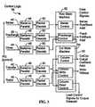
- FIG. 1shows a memory core 11 and a memory interface 13 .
- a first domainconsists of the control circuitry 15
- a second domainis the write path 17 into the memory core.
- a third pathis read data path 19 .
- Table 1indicates which clock domains are on for different power modes. The clock power to all three domains can be turned off in a standby mode.
- the control domainis turned on to enter an active mode.
- the write data path 17is additionally turned on when needed for a write operation, an active write mode.
- Read data path 19is turned on for a read operation, an active read mode.
- the present inventionprovides a memory device with multiple clock domains. Separate clocks to different portions of the control circuitry create different clock domains. The different domains are sequentially turned on as needed to limit the power consumed. The turn on time of the domains is overlapped with the latency for the memory access to make the power control transparent to the user access of the memory core.
- the present inventionseparates out the RAS control logic into a separate clock domain from the CAS control logic. This smaller amount of RAS control logic can then be left on in a standby power mode to eliminate any visible latency from a RAS signal through to data access.
- the power controlis implicit and transparent to the user.
- a RAS signalwill cause the control logic associated with the RAS control logic to activate the CAS clock domain an appropriate latency after receipt of the RAS signal without any further control over the memory interface required.
- a CAS read or write signalis received, that will implicitly, or automatically, cause the read or write clock domain to be turned on an appropriate latency after the CAS signal.
- the memory devicecan dynamically switch between a fast and a slow clock depending upon the needed data bandwidth.
- the data bandwidth across the memory interfacecan be monitored by the memory controller, and when it drops below a certain threshold, a slower clock can be used.
- the clock speedcan be dynamically increased as the bandwidth demand increases.
- clock speedcan be switched automatically depending upon data access bandwidth requirements.
- FIG. 1is a block diagram of a prior art memory system with multiple clock domains.
- FIG. 2Ais a block diagram of a memory system according to one embodiment of the invention.
- FIG. 2Bis a diagram illustrating memory operation pipelining in accordance with the invention.
- FIG. 3is a block diagram of one embodiment of the segmentation of the control logic into clock domains according to the access pipelining of FIG. 2 .
- FIG. 4is a block diagram of an alternate embodiment of FIG. 3 wherein the control logic is broken into two clock domains.
- FIG. 5is a block diagram of multiple control and data access clock domains according to one embodiment of the invention.
- FIG. 6is a timing diagram illustrating the sequencing of the clock domains of FIG. 5 .
- FIGS. 7 , 8 and 9illustrate three embodiments for dynamically varying the clock speed in accordance with data bandwidth.
- FIG. 2Ashows a memory system 10 which is controlled by a controller 12 over an interconnect bus 14 to a series of RDRAMs (Rambus dynamic random access memories) 16 .
- the interconnect bus 14includes two nine bit data busses 18 (BusDataA and BusDataB), and an eight bit primary control bus (RQ) 20 .
- a clock 22is provided in one direction along a transmit line 24 (TClk), and loops back along a receive clock line 26 (RClk).
- a low power, serial daisy-chained control interfaceis provided with daisy-chained segments 28 and a return segment 30 .
- the control sideband 28 , 30may be a bus instead of daisy-chained.
- the primary control bus and data bussescan be turned off with communication being initiated using the control sideband 28 , 30 .
- Each RDRAM 16includes multiple banks 32 of memory, each with associated core control logic 34 .
- each chipincludes interconnect logic 36 .
- FIG. 2Billustrates the pipelining of memory operations used in the present invention.
- the memory operationsare broken up into five steps: precharge, sense, transfer, data and close.
- prechargeBy breaking up the control and data transfer of a memory access operation in this manner, the operations can be pipelined to increase throughput.
- FIG. 3is a diagram illustrating one embodiment of interconnect logic 36 in a RDRAM.
- the control logicis broken up into segments, corresponding to the pipeline stages of FIG. 2B .
- the data pipeline of FIG. 2Bis not shown, since FIG. 3 shows only control logic.
- FIG. 3additionally shows a retire input 46 .
- This retire inputis used for a two-stage write operation, in which data is first written to an internal buffer, and is then written from the buffer into the memory core upon receipt of a “retire” command from the memory controller.
- Each of the control inputsis provided on a serial line which is converted into parallel with a respective converter 48 .
- the control signalsare sent as a packet, which is decoded in respective packet decode logic 50 . From there, decoded control signals are sent to either a row state machine 52 , or a column state machine 54 . The state machine will then send the appropriate control signals to the memory core control logic.
- each of the segments of FIG. 3can be made a separate clock domain, with the clock to the domain turned on and off as necessary.
- a sense operationturns on the clock domain for both the precharge control and close logic.
- a transfer operation(by the column control logic, also sometimes called the CAS control logic) turns on the retire logic (i.e., labeled the column write control logic in FIG. 3 ).
- a precharge operationcan turn on the column control logic, or parts of it.
- Signal line 55 in FIGS. 3 and 4indicates that the control column logic activates the precharge control logic so as to restart precharging (i.e., of the sense amplifiers in the memory core) after the column state machine 54 has completed transfer of information between the sense amplifiers and the data input/output buffers.
- Implicit controlis also used to turn off clock domains not needed for later steps in a particular operation sequence. For example, a close operation can turn off secondary control domains, such as the transfer and retire logic in the column state machine.
- FIG. 4shows an alternate embodiment of the invention in which the control logic 36 is broken down into two clock domains, sense clock domain 56 and column clock domain 58 .
- Row clock domain 56receives and processes row control packets while column clock domain 58 receives and processes column control packets.
- Row control packetsspecify a row address and bank address for a sense operation (also known as a RAS operation), while the column control packets indicate column address and the type of column access operation (e.g., read or write), also known as a CAS operation, to be performed.
- a sense operationalso known as a RAS operation
- the column control packetsindicate column address and the type of column access operation (e.g., read or write), also known as a CAS operation, to be performed.
- CAS operationcolumn address and the type of column access operation
- FIG. 5is a block diagram of one embodiment of the invention illustrating the different clock domains.
- FIG. 5shows a RAS clock domain 60 including control logic 62 for the RAS signal and PCH (precharge) control logic.
- a clock receiver 64is shown which connects to control bus line 66 .
- a second, CAS clock domain 68includes CAS control logic 70 and a receiver 72 .
- a write data clock domain 74includes a write input pipeline 76 and a receiver 78 .
- a read clock domain 80includes a read output pipeline 82 .
- a clock receiver 84for the main clock used for the main control bus, lines 24 and 26 of FIG. 2A .
- This clockis synchronized with a delay lock loop (DLL) 86 .
- DLLdelay lock loop
- a sideband control logic block 88is shown.
- sideband control logic 88will always be on, even in a power down mode.
- DLL 86 and clock receiver 84can be turned off via a control line 90 .
- an intermediate power modecalled a “nap” mode is used in which receiver 84 is on, but DLL 86 is in a low power configuration that provides faster synchronization time than when the DLL is entirely off.
- a memory accesscan be initiated with an appropriate control signal over sideband control line 28 .
- the sideband control logic 88also receives RAS, or RAS and CAS control data for initiating the memory access, since clock domain 60 will be off when the memory access is initiated.
- the sideband control logic 88receives RAS, but not CAS, control data, the sideband control logic 88 will turn on CAS clock domain 68 so that it is ready when the subsequent CAS signal is sent.
- the signal on line 96is sent after a period of time corresponding to the latency of the CAS signal with respect to the RAS signal. This period of time can be stored in a register in RAS control logic 62 or can be determined by the memory controller.
- the signal on line 96activates receiver 72 , and also turns on the CAS clock domain 68 by activating AND gate 98 .
- CAS control logic 70When a CAS signal is received, it will either be a CASR (CAS read) or a CASW (CAS write) signal. If it is a CASW, CAS control logic 70 will activate the write data domain 74 via control line 100 , after an appropriate latency corresponding to when the write data will be received from bus 18 . Control line 100 turns on receiver 78 , and also enables AND gate 102 to provide the clock signal to write data domain 74 .
- main control busseswhen the main control busses are in standby mode, memory accesses can be performed over the fast main control bus, with power mode transitions being implicitly controlled to make the power mode transitions transparent.
- core access latenciesare overlapped with power turn-on latencies.
- CAS-W signal 128For a write operation, similar latencies apply, as illustrated by CAS-W signal 128 . This will initiate a column write operation as illustrated by arrow 130 , and concurrently will provide a control signal as illustrated by line 132 to turn on the write data path.
- the dataFor a write operation, the data is coming in, and thus, the write data path must be turned on at a time 134 in advance of when the write data 136 is received over the data bus. Again, the latency of the power domain turn on of the write data path is transparent or hidden behind the latency of the write data arriving.
- the write data arrivingis also pipelined so that it is not provided until needed for a column write in the memory core, as illustrated by arrow 137 .
- a slower clock speedresults in lower power because the AC power to switch the capacitive load connected to the clocks is reduced proportionately to the frequency. Also, at reduced clock speeds, the device may not require a high power phase compensation circuit (DLL or PLL), which is typically required for high speed operation. Depending on the slow clock frequency, the interface may operate without phase compensation or use a lesser performance phase compensation circuit which consumes less power.
- DLLphase compensation circuit
- PLLphase compensation circuit
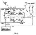
- FIG. 7illustrates one embodiment in which a memory 140 has an interface 142 with a slow clock input circuit 144 and a fast clock input circuit 146 .
- Each input circuitincludes a clock receiver 148 and a DLL or PLL 150 .
- a multiplexer 152selects whether a fast or slow clock is being used via a select control line 154 .
- the clock source 155itself provides both a fast clock and slow clock through a multiplexer 156 .
- a circuit 158 for selecting between the slow and fast clocksis preferably provided either in the controller or in a memory interconnect or some other device connected to the bus.
- the monitor circuit 158By monitoring bus traffic, the amount of bandwidth being used is determined by a monitor circuit 158 . When bus traffic exceeds a predefined threshold (i.e., more than a predefined number of memory accesses per second), the monitor circuit selects the fast clock, and otherwise it selects the slow clock. Depending on which clock is used, the fast or slow DLL or PLL and the unused receiver are preferably turned off to conserve power.
- the monitor circuit 158may be implemented using a programmed microprocessor, external to the memory circuit.
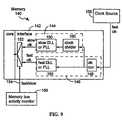
- FIG. 8is a variation of the circuit of FIG. 7 where two separate clock inputs are used, rather than a single, multiplexed line for the clock input.
Landscapes
- Engineering & Computer Science (AREA)
- Theoretical Computer Science (AREA)
- Physics & Mathematics (AREA)
- General Engineering & Computer Science (AREA)
- General Physics & Mathematics (AREA)
- Software Systems (AREA)
- Dram (AREA)
Abstract
Description
This application is a continuation of U.S. patent application Ser. No. 12/608,209, filed Oct. 29, 2009 now U.S. Pat. No. 7,986,584, which is a continuation of U.S. patent application Ser. No. 11/107,504, filed Apr. 15, 2005, now U.S. Pat. No. 7,626,880, which is continuation of U.S. patent application Ser. No. 10/742,327 filed Dec. 18, 2003, now U.S. Pat. No. 7,320,082, which is a continuation of U.S. patent application Ser. No. 09/887,181 filed Jun. 21, 2001, now U.S. Pat. No. 6,701,446, which is a continuation of U.S. patent application Ser. No. 09/169,378 filed Oct. 9, 1998, now U.S. Pat. No. 6,263,448, which claims the benefit of U.S. Provisional Application Ser. No. 60/061,664 filed Oct. 10, 1997, which are incorporated by reference in their entirety.
A related application was filed on May 7, 1996, Ser. No. 08/648,300, entitled “Asynchronous Request/Synchronous Data Dynamic Random Access Memory”, assigned to the same assignee as this application, hereby incorporated by reference as background information.
The present invention relates to power domains, and in particular to clock power domains in memory systems such as dynamic random access memories (DRAMs).
Power consumption is a constraint on computer systems both by virtue of limited power available in portable, battery-operated systems, and also limited heat dissipation for high power devices. As devices are made faster by increasing their clock speed, the power requirements also increase since clock signal lines, receivers, and other clock circuits consume more power and generate more heat as device clock rates increase.
Some memory systems operate asynchronously. Other memory systems, to increase the speed and bandwidth, operate synchronously using a clock signal. For these synchronous systems, clock power becomes an important issue at high frequencies. High power consumption by the clock signal can exceed thermal cooling limits of the package or system or cause excessive battery drain in portable devices.
In a prior Rambus dynamic random access memory (DRAM) system, illustrated inFIG. 1 , three clock domains are used to control clock power use.FIG. 1 shows amemory core 11 and amemory interface 13. A first domain consists of thecontrol circuitry 15, and a second domain is thewrite path 17 into the memory core. A third path is readdata path 19. Table 1 indicates which clock domains are on for different power modes. The clock power to all three domains can be turned off in a standby mode. The control domain is turned on to enter an active mode. Thewrite data path 17 is additionally turned on when needed for a write operation, an active write mode. Readdata path 19 is turned on for a read operation, an active read mode. In a read operation, the control domain is turned on first, to allow the control signals for the read to be provided to the memory core. Since there will be some delay before the data is available, the output data path for the data to be read need not have its clock turned on until some period of time later. Thus, there is a latency between when the control logic is turned on and provided the clock signal to when the read data output path is turned on.
| TABLE 1 | |||
| Clock Domains | |||
| power modes | rclk | sclk | tclk | ||
| standby | off | off | off | ||
| active | on | off | off | ||
| active read | on | off | on | ||
| active write | on | on | off | ||
In a prior Rambus system, the read data path is turned on automatically by the control logic when the control logic is activated for a read. Thus, a separate control signal does not need to be sent over the interface to turn on the read data path. A register will store a count corresponding to the latency from a RAS control signal to when read data will be available from the memory core, and this register value is used to control the latency of the clock turn-on for the read data path.
One disadvantage of the prior Rambus system is the additional latency required for turning on the control logic to exit the standby power mode. Since the interface control logic and datapath must be on before an incoming command can be processed and a memory operation started, the turn-on latency of the control logic and datapath directly adds to the memory access latency. This provides a power versus latency trade off.
Another method of limiting clock power consumption is to use a slower clock signal. This is done in microprocessors which have a low power or sleep mode. Typically, these are used in laptop computers in which the user can select a lower power mode, or the laptop will automatically enter the lower power or sleep mode in the absence of any user input within a predefined period of time.
The present invention provides a memory device with multiple clock domains. Separate clocks to different portions of the control circuitry create different clock domains. The different domains are sequentially turned on as needed to limit the power consumed. The turn on time of the domains is overlapped with the latency for the memory access to make the power control transparent to the user access of the memory core.
In one embodiment, the present invention separates out the RAS control logic into a separate clock domain from the CAS control logic. This smaller amount of RAS control logic can then be left on in a standby power mode to eliminate any visible latency from a RAS signal through to data access.
The write and read data paths are also in separate clock domains to further conserve power depending upon whether an operation is a read or write operation.
In one embodiment, the power control is implicit and transparent to the user. In a standby mode, a RAS signal will cause the control logic associated with the RAS control logic to activate the CAS clock domain an appropriate latency after receipt of the RAS signal without any further control over the memory interface required. When a CAS read or write signal is received, that will implicitly, or automatically, cause the read or write clock domain to be turned on an appropriate latency after the CAS signal.
In yet another embodiment of the invention, the memory device can dynamically switch between a fast and a slow clock depending upon the needed data bandwidth. The data bandwidth across the memory interface can be monitored by the memory controller, and when it drops below a certain threshold, a slower clock can be used. The clock speed can be dynamically increased as the bandwidth demand increases. Thus, rather than a coarse switch between a slow or fast clock speed depending upon user activity, clock speed can be switched automatically depending upon data access bandwidth requirements.
For a further understanding of the nature and advantages of the invention, reference should be made to the following description taken in conjunction with the accompanying drawings.
In addition a low power, serial daisy-chained control interface is provided with daisy-chainedsegments 28 and areturn segment 30. In other embodiments, thecontrol sideband control sideband
EachRDRAM 16 includesmultiple banks 32 of memory, each with associatedcore control logic 34. In addition, each chip includesinterconnect logic 36.
Each of the control inputs is provided on a serial line which is converted into parallel with arespective converter 48. The control signals are sent as a packet, which is decoded in respective packet decodelogic 50. From there, decoded control signals are sent to either arow state machine 52, or acolumn state machine 54. The state machine will then send the appropriate control signals to the memory core control logic.
Not all of the control logic segments shown inFIG. 3 need to be operating at the same time. Even in a tightly pipelined operation, if reads and writes are alternating, for example, only one of the column read and column write control logic needs to be operating each cycle. Accordingly, each of the segments ofFIG. 3 can be made a separate clock domain, with the clock to the domain turned on and off as necessary.
The turning off of clock domains as they are not needed significantly reduces power consumption and heat generation of the memory chip. As will be described below with respect toFIGS. 5 and 6 , turning on and off of each clock domain is done with timing such that it is transparent to a memory access. In other words, the memory access will take no more time to complete than if all the clocks were left on all the time. An example of how the latency of the clock domain turn on is hidden behind the normal latency of the pipeline is set forth below with respect toFIGS. 5 and 6 .
In one embodiment, a sense operation turns on the clock domain for both the precharge control and close logic. A transfer operation (by the column control logic, also sometimes called the CAS control logic) turns on the retire logic (i.e., labeled the column write control logic inFIG. 3 ). A precharge operation can turn on the column control logic, or parts of it.Signal line 55 inFIGS. 3 and 4 indicates that the control column logic activates the precharge control logic so as to restart precharging (i.e., of the sense amplifiers in the memory core) after thecolumn state machine 54 has completed transfer of information between the sense amplifiers and the data input/output buffers.
Implicit control is also used to turn off clock domains not needed for later steps in a particular operation sequence. For example, a close operation can turn off secondary control domains, such as the transfer and retire logic in the column state machine.
A second,CAS clock domain 68 includesCAS control logic 70 and areceiver 72. A writedata clock domain 74 includes awrite input pipeline 76 and areceiver 78. Aread clock domain 80 includes a readoutput pipeline 82.
In the middle ofFIG. 5 is shown aclock receiver 84 for the main clock used for the main control bus, lines24 and26 ofFIG. 2A . This clock is synchronized with a delay lock loop (DLL)86. Finally, a sidebandcontrol logic block 88 is shown.
In operation,sideband control logic 88 will always be on, even in a power down mode. In a power down mode,DLL 86 andclock receiver 84 can be turned off via acontrol line 90. Because of the significant latency required to turn onclock receiver 84 andDLL 86, an intermediate power mode, called a “nap” mode is used in whichreceiver 84 is on, butDLL 86 is in a low power configuration that provides faster synchronization time than when the DLL is entirely off. When in the nap mode, a memory access can be initiated with an appropriate control signal oversideband control line 28.
In an alternate embodiment, thesideband control logic 88 also receives RAS, or RAS and CAS control data for initiating the memory access, sinceclock domain 60 will be off when the memory access is initiated. When thesideband control logic 88 receives RAS, but not CAS, control data, thesideband control logic 88 will turn onCAS clock domain 68 so that it is ready when the subsequent CAS signal is sent.
A standby power mode is initiated by an appropriate control packet to sidebandlogic 88. This will causeDLL 86 to transition from the nap mode to an ON mode via a control signal online 92. At the same time,RAS clock domain 60 will be turned on by thesame line 92 by enabling the gating of the clock signal through ANDgate 94. Thus, in standby mode,clock receiver 84 andDLL 86 are on as well asRAS clock domain 60. When a RAS signal is received, it can be immediately processed byRAS logic 62. In anticipation of the subsequent CAS signal,control logic 62 will provide a signal on aline 96 to turn onCAS clock domain 68. This will automatically, or implicitly, turn on the CAS clock domain. Thus, the user need not send special commands to turn on and off the clock domains but rather it is done automatically in accordance with the initiation of a memory access at the appropriate time. The signal online 96 is sent after a period of time corresponding to the latency of the CAS signal with respect to the RAS signal. This period of time can be stored in a register inRAS control logic 62 or can be determined by the memory controller. The signal online 96 activatesreceiver 72, and also turns on theCAS clock domain 68 by activating ANDgate 98.
The registers for setting the latency for implicit control of clock power domains can be programmed upon device initialization, or can by dynamically varied. Alternately, instead of a register, the latency can simply be designed into the circuit.
When a CAS signal is received, it will either be a CASR (CAS read) or a CASW (CAS write) signal. If it is a CASW,CAS control logic 70 will activate thewrite data domain 74 viacontrol line 100, after an appropriate latency corresponding to when the write data will be received frombus 18.Control line 100 turns onreceiver 78, and also enables ANDgate 102 to provide the clock signal to writedata domain 74.
Similarly, for a CASR operation,CAS control logic 70 activates ANDgate 106, via a signal online 104, to provide a clock signal (TCLK) to readclock domain 80.
Thus, in the present invention, when the main control busses are in standby mode, memory accesses can be performed over the fast main control bus, with power mode transitions being implicitly controlled to make the power mode transitions transparent. In this way, core access latencies are overlapped with power turn-on latencies. By automatically turning on certain interface power modes when a particular core operation command is given, implicit power control is provided which minimizes latency and saves valuable control bandwidth (no explicit power control is needed). This will efficiently integrate power control into the memory access pipeline stream.
For a write operation, similar latencies apply, as illustrated by CAS-W signal 128. This will initiate a column write operation as illustrated byarrow 130, and concurrently will provide a control signal as illustrated by line132 to turn on the write data path. For a write operation, the data is coming in, and thus, the write data path must be turned on at a time134 in advance of when thewrite data 136 is received over the data bus. Again, the latency of the power domain turn on of the write data path is transparent or hidden behind the latency of the write data arriving. The write data arriving is also pipelined so that it is not provided until needed for a column write in the memory core, as illustrated byarrow 137.
Slow Clock
A slower clock speed results in lower power because the AC power to switch the capacitive load connected to the clocks is reduced proportionately to the frequency. Also, at reduced clock speeds, the device may not require a high power phase compensation circuit (DLL or PLL), which is typically required for high speed operation. Depending on the slow clock frequency, the interface may operate without phase compensation or use a lesser performance phase compensation circuit which consumes less power.
Theclock source 155 itself provides both a fast clock and slow clock through amultiplexer 156.
Acircuit 158 for selecting between the slow and fast clocks is preferably provided either in the controller or in a memory interconnect or some other device connected to the bus.
By monitoring bus traffic, the amount of bandwidth being used is determined by amonitor circuit 158. When bus traffic exceeds a predefined threshold (i.e., more than a predefined number of memory accesses per second), the monitor circuit selects the fast clock, and otherwise it selects the slow clock. Depending on which clock is used, the fast or slow DLL or PLL and the unused receiver are preferably turned off to conserve power. In one embodiment, themonitor circuit 158 may be implemented using a programmed microprocessor, external to the memory circuit.
As referred to above, on a transition from a slow clock to a fast clock usage, during the latency of the fast clock turn on, operations can be occurring using the slow clock.
As will be understood by those skilled in the art, the present invention may be embodied in other specific forms without departing from the spirit or central characteristics thereof. Accordingly, the foregoing description is intended to be illustrative, but not limiting, of the scope of the invention which is set forth in the following claims.
Claims (28)
1. A method of controlling a memory device that includes a clock receiver, a command interface, and a data interface, the method being carried out by a memory controller, the method comprising:
providing to the command interface, a command that specifies a write operation;
after a programmable latency period transpires from providing the command, providing to the data interface, data associated with the write operation, wherein the data interface is separate from the command interface; and
providing power mode information that controls transitions between a plurality of power modes, wherein for each power mode of the plurality of power modes, less power is consumed than the amount of power consumed during the write operation, the power modes comprising:
a mode in which the clock receiver is on and the data interface is off; and
a mode in which the clock receiver is off and the data interface is off.
2. The method ofclaim 1 , wherein:
the mode in which the clock receiver is on and the data interface is off is a nap mode; and
the mode in which the clock receiver is off and the data interface is off is a power down mode.
3. The method ofclaim 2 wherein the memory controller controls a memory device having a locked loop circuit, wherein:
during the nap mode, the locked loop circuit is in a lower power consumption configuration than when the locked loop circuit is on; and
during the power down mode, the locked loop circuit is off.
4. The method ofclaim 1 , further comprising providing, to the memory device via the command interface, address information associated with the write operation.
5. The method ofclaim 4 , wherein the command that specifies the write operation and the address information are both included in a column control packet.
6. The method ofclaim 1 , wherein the power mode information is provided in a control packet via a sideband interface to the memory device.
7. A method of controlling a memory device that includes a memory core, a clock receiver, a command interface and a data interface, the method being carried out by a memory controller, the method comprising:
providing to the command interface, a command that specifies a write operation during which the memory device inputs data, the write operation consuming an amount of power;
providing the data, associated with the write operation, to the data interface, after a programmable latency period from when the command is provided, wherein the data interface is separate from the command interface; and
indicating to the memory device, a transition to an operating mode in which less power is consumed than the amount of power consumed during the write operation, wherein the transition is one of a plurality of transitions comprising:
a transition in which, while the clock receiver is on, the command interface is turned off and the data interface is turned off; and
a transition in which the clock receiver is turned off, the command interface is turned off, and the data interface is turned off.
8. The method ofclaim 7 , wherein:
the transition in which, while the clock receiver is on, the command interface is turned off and the data interface is turned off is a transition from an active mode to a nap mode; and
the transition in which the clock receiver is turned off, the command interface is turned off, and the data interface is turned off is a transition from an active mode to a power down mode.
9. The method ofclaim 8 , wherein the memory controller controls a memory device having a locked loop circuit, wherein:
during the nap mode, the locked loop circuit is in a lower power consumption configuration than when the locked loop circuit is on; and
during the power down mode, the locked loop circuit is off.
10. The method ofclaim 7 , further comprising providing, to the memory device via the command interface, address information associated with the write operation.
11. The method ofclaim 10 , wherein the command that specifies the write operation and the address information are both included in a column control packet.
12. A method of controlling a memory device that includes a clock receiver, a locked loop circuit, a command interface and a data interface, the method being carried out by a memory controller, the method comprising:
providing to the command interface, a command that specifies a write operation during which the memory device inputs data, the write operation consuming an amount of power;
providing the data, associated with the write operation, to the data interface, after a programmable latency period from when the command is provided, wherein the data interface is separate from the command interface; and
providing information that controls transitions between a plurality of power modes, the power modes comprising:
a mode in which the clock receiver is on, the data interface is off and the locked loop circuit is on; and
a mode in which the clock receiver is off, the data interface is off, the locked loop circuit is off, and the command interface is off.
13. The method ofclaim 12 , wherein:
the mode in which the clock receiver is on, the data interface is off, and the locked loop circuit is on is a standby mode; and
the mode in which the clock receiver is off, the data interface is off, and the locked loop circuit is off is a power down mode.
14. The method ofclaim 12 , further comprising providing, to the memory device via the command interface, address information associated with the write operation.
15. The method ofclaim 14 , wherein the command that specifies the write operation and the address information are both included in a column control packet.
16. The method ofclaim 12 , wherein information that controls transitions between a plurality of power modes is provided in a control packet via a sideband interface to the memory device.
17. A method of controlling a memory device comprising a memory core, a locked loop circuit, and a clock receiver circuit to receive an external clock signal, the method being carried out by a memory controller, the method comprising:
providing to a first interface of the memory device, a command that specifies a write operation;
after a programmable latency period transpires from when the command is provided to the first interface, providing to a second interface of the memory device that is separate from the first interface, write data associated with the write operation; and
providing power mode information to the memory device, wherein the power mode information specifies a mode selected from the group of modes comprising:
a first mode in which the clock receiver, the first interface, and the second interface are off;
a second mode in which the clock receiver is on, the first interface and the second interface are off, and the locked loop circuit is in a first power state; and
a third mode in which the clock receiver is on, second interface is off, and the locked loop circuit is in a second power state.
18. The method ofclaim 17 , wherein:
the first mode is a power down mode;
the second mode is a nap mode; and
the third mode is a standby mode.
19. The method ofclaim 17 , wherein:
the first power state of the locked loop circuit is a low power mode; and
the second power state of the locked loop circuit is an on state.
20. The method ofclaim 17 , further comprising providing, to the memory device via the first interface, address information associated with the write operation.
21. The method ofclaim 20 , wherein the command that specifies the write operation and the address information are both included in a column control packet.
22. The method ofclaim 17 , wherein the power mode information is provided in a control packet via a sideband interface to the memory device.
23. A method of controlling a memory device comprising a memory core, a locked loop circuit, and a clock receiver circuit to receive an external clock signal, the method being carried out by a memory controller, the method comprising:
providing to a command interface of the memory device, a command that specifies a write operation;
after a programmable latency period transpires from when the command is provided to the command interface, providing to a data interface of the memory device, write data associated with the write operation; and
providing power mode information to the memory device, wherein the power mode information specifies a mode selected from the group of modes comprising:
a first mode in which the clock receiver, the command interface, and the data interface are off;
a second mode in which the clock receiver is on, the command interface and the data interface are off, and the locked loop circuit is in a first power state; and
a third mode in which the clock receiver is on, the data interface is off, and the locked loop circuit is in a second power state.
24. The method ofclaim 23 , wherein:
the first mode is a power down mode;
the second mode is a nap mode; and
the third mode is a standby mode.
25. The method ofclaim 23 , wherein:
the first power state of the locked loop circuit is a low power mode; and
the second power state of the locked loop circuit is an on state.
26. The method ofclaim 23 , further comprising providing, to the memory device via the command interface, address information associated with the write operation.
27. The method ofclaim 26 , wherein the command that specifies the write operation and the address information are both included in a column control packet.
28. The method ofclaim 23 , wherein the power mode information is provided in a control packet via a sideband interface to the memory device.
Priority Applications (3)
| Application Number | Priority Date | Filing Date | Title |
|---|---|---|---|
| US12/975,322US8248884B2 (en) | 1997-10-10 | 2010-12-21 | Method of controlling a memory device having multiple power modes |
| US13/253,911US20120057424A1 (en) | 1997-10-10 | 2011-10-05 | Memory Device Having Multiple Power Modes |
| US13/352,177US8305839B2 (en) | 1997-10-10 | 2012-01-17 | Memory device having multiple power modes |
Applications Claiming Priority (7)
| Application Number | Priority Date | Filing Date | Title |
|---|---|---|---|
| US6166497P | 1997-10-10 | 1997-10-10 | |
| US09/169,378US6263448B1 (en) | 1997-10-10 | 1998-10-09 | Power control system for synchronous memory device |
| US09/887,181US6701446B2 (en) | 1997-10-10 | 2001-06-21 | Power control system for synchronous memory device |
| US10/742,327US7320082B2 (en) | 1997-10-10 | 2003-12-18 | Power control system for synchronous memory device |
| US11/107,504US7626880B2 (en) | 1997-10-10 | 2005-04-15 | Memory device having a read pipeline and a delay locked loop |
| US12/608,209US7986584B2 (en) | 1997-10-10 | 2009-10-29 | Memory device having multiple power modes |
| US12/975,322US8248884B2 (en) | 1997-10-10 | 2010-12-21 | Method of controlling a memory device having multiple power modes |
Related Parent Applications (1)
| Application Number | Title | Priority Date | Filing Date |
|---|---|---|---|
| US12/608,209ContinuationUS7986584B2 (en) | 1997-10-10 | 2009-10-29 | Memory device having multiple power modes |
Related Child Applications (2)
| Application Number | Title | Priority Date | Filing Date |
|---|---|---|---|
| US13/253,911ContinuationUS20120057424A1 (en) | 1997-10-10 | 2011-10-05 | Memory Device Having Multiple Power Modes |
| US13/352,177ContinuationUS8305839B2 (en) | 1997-10-10 | 2012-01-17 | Memory device having multiple power modes |
Publications (2)
| Publication Number | Publication Date |
|---|---|
| US20110090755A1 US20110090755A1 (en) | 2011-04-21 |
| US8248884B2true US8248884B2 (en) | 2012-08-21 |
Family
ID=22037289
Family Applications (9)
| Application Number | Title | Priority Date | Filing Date |
|---|---|---|---|
| US09/169,378Expired - LifetimeUS6263448B1 (en) | 1997-10-10 | 1998-10-09 | Power control system for synchronous memory device |
| US09/887,181Expired - LifetimeUS6701446B2 (en) | 1997-10-10 | 2001-06-21 | Power control system for synchronous memory device |
| US10/742,327Expired - Fee RelatedUS7320082B2 (en) | 1997-10-10 | 2003-12-18 | Power control system for synchronous memory device |
| US11/107,504Expired - Fee RelatedUS7626880B2 (en) | 1997-10-10 | 2005-04-15 | Memory device having a read pipeline and a delay locked loop |
| US11/856,661AbandonedUS20080002516A1 (en) | 1997-10-10 | 2007-09-17 | Memory Device Having a Delay Locked Loop and Multiple Power Modes |
| US12/608,209Expired - Fee RelatedUS7986584B2 (en) | 1997-10-10 | 2009-10-29 | Memory device having multiple power modes |
| US12/975,322Expired - Fee RelatedUS8248884B2 (en) | 1997-10-10 | 2010-12-21 | Method of controlling a memory device having multiple power modes |
| US13/253,911AbandonedUS20120057424A1 (en) | 1997-10-10 | 2011-10-05 | Memory Device Having Multiple Power Modes |
| US13/352,177Expired - Fee RelatedUS8305839B2 (en) | 1997-10-10 | 2012-01-17 | Memory device having multiple power modes |
Family Applications Before (6)
| Application Number | Title | Priority Date | Filing Date |
|---|---|---|---|
| US09/169,378Expired - LifetimeUS6263448B1 (en) | 1997-10-10 | 1998-10-09 | Power control system for synchronous memory device |
| US09/887,181Expired - LifetimeUS6701446B2 (en) | 1997-10-10 | 2001-06-21 | Power control system for synchronous memory device |
| US10/742,327Expired - Fee RelatedUS7320082B2 (en) | 1997-10-10 | 2003-12-18 | Power control system for synchronous memory device |
| US11/107,504Expired - Fee RelatedUS7626880B2 (en) | 1997-10-10 | 2005-04-15 | Memory device having a read pipeline and a delay locked loop |
| US11/856,661AbandonedUS20080002516A1 (en) | 1997-10-10 | 2007-09-17 | Memory Device Having a Delay Locked Loop and Multiple Power Modes |
| US12/608,209Expired - Fee RelatedUS7986584B2 (en) | 1997-10-10 | 2009-10-29 | Memory device having multiple power modes |
Family Applications After (2)
| Application Number | Title | Priority Date | Filing Date |
|---|---|---|---|
| US13/253,911AbandonedUS20120057424A1 (en) | 1997-10-10 | 2011-10-05 | Memory Device Having Multiple Power Modes |
| US13/352,177Expired - Fee RelatedUS8305839B2 (en) | 1997-10-10 | 2012-01-17 | Memory device having multiple power modes |
Country Status (3)
| Country | Link |
|---|---|
| US (9) | US6263448B1 (en) |
| AU (1) | AU9798798A (en) |
| WO (1) | WO1999019874A1 (en) |
Families Citing this family (141)
| Publication number | Priority date | Publication date | Assignee | Title |
|---|---|---|---|---|
| US6401167B1 (en)* | 1997-10-10 | 2002-06-04 | Rambus Incorporated | High performance cost optimized memory |
| WO1999019805A1 (en) | 1997-10-10 | 1999-04-22 | Rambus Incorporated | Method and apparatus for two step memory write operations |
| US6263448B1 (en) | 1997-10-10 | 2001-07-17 | Rambus Inc. | Power control system for synchronous memory device |
| US6154821A (en)* | 1998-03-10 | 2000-11-28 | Rambus Inc. | Method and apparatus for initializing dynamic random access memory (DRAM) devices by levelizing a read domain |
| US6657634B1 (en) | 1999-02-25 | 2003-12-02 | Ati International Srl | Dynamic graphics and/or video memory power reducing circuit and method |
| JP4077979B2 (en)* | 1999-05-27 | 2008-04-23 | 株式会社日立製作所 | Semiconductor integrated circuit device |
| US6848058B1 (en)* | 1999-06-04 | 2005-01-25 | Ati International Srl | Power reduction circuit and method with multi clock branch control |
| US6571333B1 (en)* | 1999-11-05 | 2003-05-27 | Intel Corporation | Initializing a memory controller by executing software in second memory to wakeup a system |
| KR100575864B1 (en)* | 1999-12-30 | 2006-05-03 | 주식회사 하이닉스반도체 | Lambeth Dram |
| US7010642B2 (en) | 2000-01-05 | 2006-03-07 | Rambus Inc. | System featuring a controller device and a memory module that includes an integrated circuit buffer device and a plurality of integrated circuit memory devices |
| US7363422B2 (en) | 2000-01-05 | 2008-04-22 | Rambus Inc. | Configurable width buffered module |
| IL134512A0 (en)* | 2000-02-13 | 2001-04-30 | Dspc Tech Ltd | Offline acquisition method for cdma |
| KR100322546B1 (en)* | 2000-05-08 | 2002-03-18 | 윤종용 | Interface system between memory and memory controller using independent supply voltage |
| JP3878431B2 (en)* | 2000-06-16 | 2007-02-07 | 株式会社ルネサステクノロジ | Semiconductor integrated circuit device |
| US7007187B1 (en)* | 2000-06-30 | 2006-02-28 | Intel Corporation | Method and apparatus for an integrated circuit having flexible-ratio frequency domain cross-overs |
| US6934785B2 (en) | 2000-12-22 | 2005-08-23 | Micron Technology, Inc. | High speed interface with looped bus |
| US7301987B2 (en)* | 2001-02-08 | 2007-11-27 | Intel Corporation | Background processing and searching for a communication channel |
| US6791380B2 (en)* | 2001-11-27 | 2004-09-14 | Winbond Electronics Corporation | Universal clock generator |
| US6910145B2 (en)* | 2001-12-13 | 2005-06-21 | Emc Corporation | Data transmission across asynchronous clock domains |
| US7076674B2 (en)* | 2001-12-19 | 2006-07-11 | Hewlett-Packard Development Company L.P. | Portable computer having dual clock mode |
| US6859868B2 (en) | 2002-02-07 | 2005-02-22 | Sun Microsystems, Inc. | Object addressed memory hierarchy |
| DE10219652B4 (en)* | 2002-05-02 | 2007-01-11 | Infineon Technologies Ag | Memory circuit and method for operating a memory circuit |
| US6950105B2 (en)* | 2002-06-03 | 2005-09-27 | Ati Technologies Inc. | Power consumption management in a video graphics accelerator |
| US7076681B2 (en)* | 2002-07-02 | 2006-07-11 | International Business Machines Corporation | Processor with demand-driven clock throttling power reduction |
| US6948043B2 (en)* | 2002-08-12 | 2005-09-20 | Hewlett-Packard Development Company, L.P. | Management of a memory subsystem |
| KR100546319B1 (en)* | 2003-02-26 | 2006-01-26 | 삼성전자주식회사 | I / O data pipeline circuit of a semiconductor memory device and the semiconductor memory device |
| CN100399262C (en)* | 2003-08-26 | 2008-07-02 | 国际商业机器公司 | Processor with demand-driven clock throttling for power reduction |
| US7343508B2 (en)* | 2004-03-05 | 2008-03-11 | Ati Technologies Inc. | Dynamic clock control circuit for graphics engine clock and memory clock and method |
| US7500123B2 (en)* | 2004-06-28 | 2009-03-03 | Ati Technologies Ulc | Apparatus and method for reducing power consumption in a graphics processing device |
| US7827424B2 (en)* | 2004-07-29 | 2010-11-02 | Ati Technologies Ulc | Dynamic clock control circuit and method |
| US7226857B2 (en) | 2004-07-30 | 2007-06-05 | Micron Technology, Inc. | Front-end processing of nickel plated bond pads |
| JP4662536B2 (en) | 2004-12-28 | 2011-03-30 | パナソニック株式会社 | Timing adjustment method and apparatus |
| US7782805B1 (en) | 2005-02-08 | 2010-08-24 | Med Belhadj | High speed packet interface and method |
| US7401245B2 (en)* | 2005-04-29 | 2008-07-15 | Hewlett-Packard Development Company, L.P. | Count calibration for synchronous data transfer between clock domains |
| US7800621B2 (en) | 2005-05-16 | 2010-09-21 | Ati Technologies Inc. | Apparatus and methods for control of a memory controller |
| US7421599B2 (en)* | 2005-06-09 | 2008-09-02 | International Business Machines Corporation | Power management server and method for managing power consumption |
| US7467311B2 (en)* | 2005-06-09 | 2008-12-16 | International Business Machines Corporation | Distributed system and method for managing power usage among server data processing systems |
| US7664968B2 (en)* | 2005-06-09 | 2010-02-16 | International Business Machines Corporation | System and method for managing power usage of a data processing system subsystem |
| US7509506B2 (en)* | 2005-06-09 | 2009-03-24 | International Business Machines Corporation | Hierarchical system and method for managing power usage among server data processing systems |
| US7386743B2 (en) | 2005-06-09 | 2008-06-10 | International Business Machines Corporation | Power-managed server and method for managing power consumption |
| US7332950B2 (en)* | 2005-06-14 | 2008-02-19 | Micron Technology, Inc. | DLL measure initialization circuit for high frequency operation |
| US8386722B1 (en) | 2008-06-23 | 2013-02-26 | Google Inc. | Stacked DIMM memory interface |
| US7386656B2 (en) | 2006-07-31 | 2008-06-10 | Metaram, Inc. | Interface circuit system and method for performing power management operations in conjunction with only a portion of a memory circuit |
| US20080028136A1 (en) | 2006-07-31 | 2008-01-31 | Schakel Keith R | Method and apparatus for refresh management of memory modules |
| US9507739B2 (en) | 2005-06-24 | 2016-11-29 | Google Inc. | Configurable memory circuit system and method |
| US8244971B2 (en) | 2006-07-31 | 2012-08-14 | Google Inc. | Memory circuit system and method |
| US8359187B2 (en) | 2005-06-24 | 2013-01-22 | Google Inc. | Simulating a different number of memory circuit devices |
| US8055833B2 (en) | 2006-10-05 | 2011-11-08 | Google Inc. | System and method for increasing capacity, performance, and flexibility of flash storage |
| US10013371B2 (en)* | 2005-06-24 | 2018-07-03 | Google Llc | Configurable memory circuit system and method |
| US7609567B2 (en) | 2005-06-24 | 2009-10-27 | Metaram, Inc. | System and method for simulating an aspect of a memory circuit |
| KR101377305B1 (en)* | 2005-06-24 | 2014-03-25 | 구글 인코포레이티드 | An integrated memory core and memory interface circuit |
| US9171585B2 (en) | 2005-06-24 | 2015-10-27 | Google Inc. | Configurable memory circuit system and method |
| US8130560B1 (en) | 2006-11-13 | 2012-03-06 | Google Inc. | Multi-rank partial width memory modules |
| US8327104B2 (en) | 2006-07-31 | 2012-12-04 | Google Inc. | Adjusting the timing of signals associated with a memory system |
| US8111566B1 (en) | 2007-11-16 | 2012-02-07 | Google, Inc. | Optimal channel design for memory devices for providing a high-speed memory interface |
| US8081474B1 (en) | 2007-12-18 | 2011-12-20 | Google Inc. | Embossed heat spreader |
| US7392338B2 (en)* | 2006-07-31 | 2008-06-24 | Metaram, Inc. | Interface circuit system and method for autonomously performing power management operations in conjunction with a plurality of memory circuits |
| US8397013B1 (en) | 2006-10-05 | 2013-03-12 | Google Inc. | Hybrid memory module |
| US7580312B2 (en) | 2006-07-31 | 2009-08-25 | Metaram, Inc. | Power saving system and method for use with a plurality of memory circuits |
| US8060774B2 (en) | 2005-06-24 | 2011-11-15 | Google Inc. | Memory systems and memory modules |
| US8438328B2 (en) | 2008-02-21 | 2013-05-07 | Google Inc. | Emulation of abstracted DIMMs using abstracted DRAMs |
| US7590796B2 (en) | 2006-07-31 | 2009-09-15 | Metaram, Inc. | System and method for power management in memory systems |
| US8090897B2 (en) | 2006-07-31 | 2012-01-03 | Google Inc. | System and method for simulating an aspect of a memory circuit |
| US8077535B2 (en) | 2006-07-31 | 2011-12-13 | Google Inc. | Memory refresh apparatus and method |
| US9542352B2 (en) | 2006-02-09 | 2017-01-10 | Google Inc. | System and method for reducing command scheduling constraints of memory circuits |
| US20080082763A1 (en) | 2006-10-02 | 2008-04-03 | Metaram, Inc. | Apparatus and method for power management of memory circuits by a system or component thereof |
| US8335894B1 (en) | 2008-07-25 | 2012-12-18 | Google Inc. | Configurable memory system with interface circuit |
| US8089795B2 (en) | 2006-02-09 | 2012-01-03 | Google Inc. | Memory module with memory stack and interface with enhanced capabilities |
| US8041881B2 (en)* | 2006-07-31 | 2011-10-18 | Google Inc. | Memory device with emulated characteristics |
| US8796830B1 (en) | 2006-09-01 | 2014-08-05 | Google Inc. | Stackable low-profile lead frame package |
| EP1742143B1 (en)* | 2005-07-06 | 2018-11-21 | STMicroelectronics Srl | Method and system for power consumption management, and corresponding computer program product |
| US7660183B2 (en)* | 2005-08-01 | 2010-02-09 | Rambus Inc. | Low power memory device |
| WO2007028109A2 (en) | 2005-09-02 | 2007-03-08 | Metaram, Inc. | Methods and apparatus of stacking drams |
| US11328764B2 (en) | 2005-09-26 | 2022-05-10 | Rambus Inc. | Memory system topologies including a memory die stack |
| US7562271B2 (en) | 2005-09-26 | 2009-07-14 | Rambus Inc. | Memory system topologies including a buffer device and an integrated circuit memory device |
| US7464225B2 (en) | 2005-09-26 | 2008-12-09 | Rambus Inc. | Memory module including a plurality of integrated circuit memory devices and a plurality of buffer devices in a matrix topology |
| US7415581B2 (en)* | 2005-10-04 | 2008-08-19 | Infineon Technologies Ag | Semiconductor memory chip |
| US9632929B2 (en) | 2006-02-09 | 2017-04-25 | Google Inc. | Translating an address associated with a command communicated between a system and memory circuits |
| DE102006009026A1 (en)* | 2006-02-27 | 2007-08-30 | Infineon Technologies Ag | Memory arrangement for computer system, comprises two packet processing devices present for coding or decoding the packets, where different memory bank access devices are assigned to two packet processing devices |
| DE102006009027A1 (en)* | 2006-02-27 | 2007-08-30 | Infineon Technologies Ag | Memory arrangement comprises interface, two memory banks with one memory cell, and two memory bank access devices, intermediate storage devices are provided for intermediate saving of data |
| US7617404B2 (en)* | 2006-03-28 | 2009-11-10 | Advanced Micro Devices, Inc. | In-band power management in a communication link |
| US7607031B2 (en)* | 2006-03-28 | 2009-10-20 | Advanced Micro Devices, Inc. | Power management in a communication link |
| US20080028135A1 (en)* | 2006-07-31 | 2008-01-31 | Metaram, Inc. | Multiple-component memory interface system and method |
| US7724589B2 (en) | 2006-07-31 | 2010-05-25 | Google Inc. | System and method for delaying a signal communicated from a system to at least one of a plurality of memory circuits |
| US20080201588A1 (en)* | 2007-02-16 | 2008-08-21 | Mosaid Technologies Incorporated | Semiconductor device and method for reducing power consumption in a system having interconnected devices |
| US7908501B2 (en)* | 2007-03-23 | 2011-03-15 | Silicon Image, Inc. | Progressive power control of a multi-port memory device |
| US7881147B2 (en)* | 2007-05-31 | 2011-02-01 | Qualcomm Incorporated | Clock and control signal generation for high performance memory devices |
| TW200849087A (en)* | 2007-06-01 | 2008-12-16 | Holtek Semiconductor Inc | Method of accelerating the excution of repeatative commands and its micro controller |
| US8209479B2 (en) | 2007-07-18 | 2012-06-26 | Google Inc. | Memory circuit system and method |
| US7899983B2 (en) | 2007-08-31 | 2011-03-01 | International Business Machines Corporation | Buffered memory module supporting double the memory device data width in the same physical space as a conventional memory module |
| US8086936B2 (en)* | 2007-08-31 | 2011-12-27 | International Business Machines Corporation | Performing error correction at a memory device level that is transparent to a memory channel |
| US7865674B2 (en)* | 2007-08-31 | 2011-01-04 | International Business Machines Corporation | System for enhancing the memory bandwidth available through a memory module |
| US8082482B2 (en)* | 2007-08-31 | 2011-12-20 | International Business Machines Corporation | System for performing error correction operations in a memory hub device of a memory module |
| US7818497B2 (en)* | 2007-08-31 | 2010-10-19 | International Business Machines Corporation | Buffered memory module supporting two independent memory channels |
| US7840748B2 (en)* | 2007-08-31 | 2010-11-23 | International Business Machines Corporation | Buffered memory module with multiple memory device data interface ports supporting double the memory capacity |
| US7584308B2 (en)* | 2007-08-31 | 2009-09-01 | International Business Machines Corporation | System for supporting partial cache line write operations to a memory module to reduce write data traffic on a memory channel |
| US7861014B2 (en)* | 2007-08-31 | 2010-12-28 | International Business Machines Corporation | System for supporting partial cache line read operations to a memory module to reduce read data traffic on a memory channel |
| US7558887B2 (en)* | 2007-09-05 | 2009-07-07 | International Business Machines Corporation | Method for supporting partial cache line read and write operations to a memory module to reduce read and write data traffic on a memory channel |
| US8019919B2 (en)* | 2007-09-05 | 2011-09-13 | International Business Machines Corporation | Method for enhancing the memory bandwidth available through a memory module |
| US8080874B1 (en) | 2007-09-14 | 2011-12-20 | Google Inc. | Providing additional space between an integrated circuit and a circuit board for positioning a component therebetween |
| KR100873624B1 (en)* | 2007-11-09 | 2008-12-12 | 주식회사 하이닉스반도체 | Power down mode control device and DLL circuit including the same |
| US8208593B2 (en)* | 2007-11-19 | 2012-06-26 | Rambus Inc. | Partial-rate transfer mode for fixed-clock-rate interface |
| US7930470B2 (en)* | 2008-01-24 | 2011-04-19 | International Business Machines Corporation | System to enable a memory hub device to manage thermal conditions at a memory device level transparent to a memory controller |
| US8140936B2 (en)* | 2008-01-24 | 2012-03-20 | International Business Machines Corporation | System for a combined error correction code and cyclic redundancy check code for a memory channel |
| US7930469B2 (en) | 2008-01-24 | 2011-04-19 | International Business Machines Corporation | System to provide memory system power reduction without reducing overall memory system performance |
| US7925826B2 (en)* | 2008-01-24 | 2011-04-12 | International Business Machines Corporation | System to increase the overall bandwidth of a memory channel by allowing the memory channel to operate at a frequency independent from a memory device frequency |
| US7925825B2 (en)* | 2008-01-24 | 2011-04-12 | International Business Machines Corporation | System to support a full asynchronous interface within a memory hub device |
| US7770077B2 (en)* | 2008-01-24 | 2010-08-03 | International Business Machines Corporation | Using cache that is embedded in a memory hub to replace failed memory cells in a memory subsystem |
| US7925824B2 (en)* | 2008-01-24 | 2011-04-12 | International Business Machines Corporation | System to reduce latency by running a memory channel frequency fully asynchronous from a memory device frequency |
| KR100940838B1 (en)* | 2008-06-04 | 2010-02-04 | 주식회사 하이닉스반도체 | Apparatus and method for generating clock signal of semiconductor integrated circuit |
| KR100945802B1 (en) | 2008-06-24 | 2010-03-08 | 주식회사 하이닉스반도체 | Semiconductor Integrated Circuits Generate Clock |
| US8135972B2 (en)* | 2009-03-10 | 2012-03-13 | Cortina Systems, Inc. | Data interface power consumption control |
| DE202010017690U1 (en) | 2009-06-09 | 2012-05-29 | Google, Inc. | Programming dimming terminating resistor values |
| US9760333B2 (en)* | 2009-08-24 | 2017-09-12 | Ati Technologies Ulc | Pixel clocking method and apparatus |
| US9348355B2 (en) | 2009-08-24 | 2016-05-24 | Ati Technologies Ulc | Display link clocking method and apparatus |
| KR101622195B1 (en)* | 2009-11-05 | 2016-05-18 | 삼성전자주식회사 | Apparatus and method for adaptive frequency scaling |
| US8269525B2 (en)* | 2009-11-17 | 2012-09-18 | Ati Technologies Ulc | Logic cell having reduced spurious toggling |
| US9041720B2 (en)* | 2009-12-18 | 2015-05-26 | Advanced Micro Devices, Inc. | Static image retiling and power management method and circuit |
| US8805590B2 (en)* | 2009-12-24 | 2014-08-12 | International Business Machines Corporation | Fan speed control of rack devices where sum of device airflows is greater than maximum airflow of rack |
| US8266471B2 (en)* | 2010-02-09 | 2012-09-11 | Mosys, Inc. | Memory device including a memory block having a fixed latency data output |
| US8438410B2 (en)* | 2010-06-23 | 2013-05-07 | Intel Corporation | Memory power management via dynamic memory operation states |
| US8327172B2 (en)* | 2010-06-23 | 2012-12-04 | Intel Corporation | Adaptive memory frequency scaling |
| US8799685B2 (en) | 2010-08-25 | 2014-08-05 | Advanced Micro Devices, Inc. | Circuits and methods for providing adjustable power consumption |
| KR101796116B1 (en) | 2010-10-20 | 2017-11-10 | 삼성전자 주식회사 | Semiconductor device, memory module and memory system having the same and operating method thereof |
| WO2012115839A1 (en) | 2011-02-23 | 2012-08-30 | Rambus Inc. | Protocol for memory power-mode control |
| US9098281B2 (en) | 2011-03-09 | 2015-08-04 | Rambus Inc. | Power-management for integrated circuits |
| US20130148447A1 (en)* | 2011-12-07 | 2013-06-13 | Ian P. Shaeffer | Reducing Power Consumption in a Memory System |
| US8804449B2 (en)* | 2012-09-06 | 2014-08-12 | Micron Technology, Inc. | Apparatus and methods to provide power management for memory devices |
| US9568980B2 (en) | 2012-09-11 | 2017-02-14 | Rambus Inc. | Using dynamic bursts to support frequency-agile memory interfaces |
| US9158679B2 (en) | 2012-10-10 | 2015-10-13 | Rambus Inc. | Data buffer with a strobe-based primary interface and a strobe-less secondary interface |
| KR102012904B1 (en)* | 2012-11-30 | 2019-08-21 | 삼성전자주식회사 | Semiconductor integrated chip and operating method thereof |
| US20140289446A1 (en)* | 2013-03-21 | 2014-09-25 | Kabushiki Kaisha Toshiba | Memory system and memory |
| KR102086719B1 (en)* | 2014-03-11 | 2020-03-09 | 삼성전자주식회사 | Memory controller and memory system including the same |
| KR20170049193A (en) | 2015-10-28 | 2017-05-10 | 삼성전자주식회사 | Delay locked loop circuit and semiconductor memory device including the same |
| US10447461B2 (en)* | 2015-12-01 | 2019-10-15 | Infineon Technologies Austria Ag | Accessing data via different clocks |
| US10175905B2 (en) | 2016-09-13 | 2019-01-08 | Apple Inc. | Systems and methods for dynamically switching memory performance states |
| US9740267B1 (en) | 2016-10-31 | 2017-08-22 | International Business Machines Corporation | Adjusting power management controls of a memory based on traffic |
| US11417370B2 (en)* | 2020-08-12 | 2022-08-16 | Taiwan Semiconductor Manufacturing Company, Ltd. | Memory device |
| US12056394B2 (en) | 2020-08-13 | 2024-08-06 | Cadence Design Systems, Inc. | Memory interface training |
| US12142344B2 (en) | 2021-10-19 | 2024-11-12 | Nvidia Corporation | Techniques for reducing DRAM power usage in performing read and write operations |
| DE112022005040T5 (en)* | 2021-10-19 | 2024-08-14 | Nvidia Corporation | TECHNIQUES TO REDUCE POWER CONSUMPTION WHEN PERFORMING READ AND WRITE OPERATIONS |
Citations (134)
| Publication number | Priority date | Publication date | Assignee | Title |
|---|---|---|---|---|
| US4293932A (en) | 1980-02-11 | 1981-10-06 | Texas Instruments Incorporated | Refresh operations for semiconductor memory |
| US4334295A (en) | 1979-05-08 | 1982-06-08 | Nippon Electric Co., Ltd. | Memory device |
| US4388686A (en) | 1980-10-20 | 1983-06-14 | General Electric Company | Communication system for distributed control arrangement |
| EP0112140A1 (en) | 1982-12-13 | 1984-06-27 | Magna International Inc. | Drive system for an electrically operated remote control rearview mirror |
| US4484308A (en) | 1982-09-23 | 1984-11-20 | Motorola, Inc. | Serial data mode circuit for a memory |
| US4485461A (en) | 1982-04-12 | 1984-11-27 | Nippon Electric Co., Ltd. | Memory circuit |
| US4528661A (en) | 1983-02-14 | 1985-07-09 | Prime Computer, Inc. | Ring communications system |
| US4617647A (en) | 1982-12-14 | 1986-10-14 | Nec Corporation | Memory circuit |
| US4649522A (en) | 1985-02-11 | 1987-03-10 | At&T Bell Laboratories | Fast column access memory |
| US4694197A (en) | 1986-01-06 | 1987-09-15 | Rca Corporation | Control signal generator |
| US4734880A (en) | 1983-04-12 | 1988-03-29 | Sony Corporation | Dynamic random access memory arrangements having WE, RAS, and CAS derived from a single system clock |
| US4744062A (en) | 1985-04-23 | 1988-05-10 | Hitachi, Ltd. | Semiconductor integrated circuit with nonvolatile memory |
| US4792929A (en) | 1987-03-23 | 1988-12-20 | Zenith Electronics Corporation | Data processing system with extended memory access |
| US4792926A (en) | 1985-12-09 | 1988-12-20 | Kabushiki Kaisha Toshiba | High speed memory system for use with a control bus bearing contiguous segmentially intermixed data read and data write request signals |
| US4800530A (en) | 1986-08-19 | 1989-01-24 | Kabushiki Kasiha Toshiba | Semiconductor memory system with dynamic random access memory cells |
| US4823324A (en) | 1985-09-23 | 1989-04-18 | Ncr Corporation | Page mode operation of main system memory in a medium scale computer |
| US4825411A (en) | 1986-06-24 | 1989-04-25 | Mitsubishi Denki Kabushiki Kaisha | Dual-port memory with asynchronous control of serial data memory transfer |
| US4831597A (en) | 1986-11-25 | 1989-05-16 | Kabushiki Kaisha Toshiba | Dynamic random access semiconductor memory wherein the RAS and CAS strobes respectively select the bit line and word line pairs |
| US4833656A (en) | 1986-11-11 | 1989-05-23 | Mitsubishi Denki Kabushiki Kaisha | Fast access circuit for dynamic type semiconductor memory device |
| US4839856A (en) | 1985-12-23 | 1989-06-13 | Kabushiki Kaisha Toshiba | Memory access control circuit |
| US4875192A (en) | 1983-12-23 | 1989-10-17 | Hitachi, Ltd. | Semiconductor memory with an improved nibble mode arrangement |
| US4901282A (en) | 1985-10-31 | 1990-02-13 | Mitsubishi Denki Kabushiki Kaisha | Power efficient static-column DRAM |
| US4970690A (en) | 1989-07-31 | 1990-11-13 | Atari Games Corporation | Memory cell arrangement supporting bit-serial arithmetic |
| US4979145A (en) | 1986-05-01 | 1990-12-18 | Motorola, Inc. | Structure and method for improving high speed data rate in a DRAM |
| US5007028A (en) | 1988-01-19 | 1991-04-09 | Kabushiki Kaisha Toshiba | Multiport memory with improved timing of word line selection |
| US5034917A (en) | 1988-05-26 | 1991-07-23 | Bland Patrick M | Computer system including a page mode memory with decreased access time and method of operation thereof |
| US5077693A (en) | 1990-08-06 | 1991-12-31 | Motorola, Inc. | Dynamic random access memory |
| US5083296A (en) | 1989-08-28 | 1992-01-21 | Hitachi, Ltd. | Semiconductor memory with alternately multiplexed row and column addressing |
| US5088062A (en) | 1989-03-15 | 1992-02-11 | Matsushita Electronics Corporation | Memory device having common data lines for reading and writing |
| US5111386A (en) | 1987-12-02 | 1992-05-05 | Mitsubishi Denki Kabushiki Kaisha | Cache contained type semiconductor memory device and operating method therefor |
| US5124589A (en) | 1990-06-19 | 1992-06-23 | Mitsubishi Denki Kabushiki Kaisha | Semiconductor integrated circuit capable of synchronous and asynchronous operations and operating method therefor |
| US5150329A (en) | 1989-07-21 | 1992-09-22 | Nec Corporation | Dynamic memory with a refresh control circuit |
| US5173878A (en) | 1987-11-25 | 1992-12-22 | Kabushiki Kaisha Toshiba | Semiconductor memory including address multiplexing circuitry for changing the order of supplying row and column addresses between read and write cycles |
| US5179687A (en) | 1987-09-26 | 1993-01-12 | Mitsubishi Denki Kabushiki Kaisha | Semiconductor memory device containing a cache and an operation method thereof |
| US5185719A (en) | 1989-10-14 | 1993-02-09 | International Business Machines Corp. | High speed dynamic, random access memory with extended reset/precharge time |
| US5193072A (en) | 1990-12-21 | 1993-03-09 | Vlsi Technology, Inc. | Hidden refresh of a dynamic random access memory |
| US5202857A (en) | 1990-11-07 | 1993-04-13 | Emc Corporation | System for generating memory timing and reducing memory access time |
| US5218686A (en) | 1989-11-03 | 1993-06-08 | Compaq Computer Corporation | Combined synchronous and asynchronous memory controller |
| US5218572A (en) | 1991-06-14 | 1993-06-08 | Samsung Electronics Co., Ltd. | Semiconductor memory device |
| US5226147A (en) | 1987-11-06 | 1993-07-06 | Mitsubishi Denki Kabushiki Kaisha | Semiconductor memory device for simple cache system |
| US5249282A (en) | 1990-11-21 | 1993-09-28 | Benchmarq Microelectronics, Inc. | Integrated cache memory system with primary and secondary cache memories |
| US5249277A (en) | 1990-08-08 | 1993-09-28 | Compuadd Corporation | Optimized performance memory method and system |
| US5251178A (en) | 1991-03-06 | 1993-10-05 | Childers Jimmie D | Low-power integrated circuit memory |
| US5258953A (en) | 1991-06-27 | 1993-11-02 | Nec Corporation | Semiconductor memory device |
| US5260905A (en) | 1990-09-03 | 1993-11-09 | Matsushita Electric Industrial Co., Ltd. | Multi-port memory |
| US5267200A (en) | 1988-08-31 | 1993-11-30 | Mitsubishi Denki Kabushiki Kaisha | Semiconductor memory device and operating method thereof with transfer transistor used as a holding means |
| US5268639A (en) | 1992-06-05 | 1993-12-07 | Rambus, Inc. | Testing timing parameters of high speed integrated circuit devices |
| US5268865A (en) | 1990-07-25 | 1993-12-07 | Oki Electric Industry Co., Ltd. | Synchronous burst-access memory |
| US5274788A (en) | 1990-02-26 | 1993-12-28 | Nec Corporation | High speed memory access for a data processor |
| US5276858A (en) | 1991-12-26 | 1994-01-04 | Intel Corporation | Memory controller with integrated delay line circuitry |
| US5278792A (en) | 1991-01-28 | 1994-01-11 | Mitsubishi Denki Kabushiki Kaisha | Semiconductor memory device with dummy cycle operation |
| US5278789A (en) | 1990-12-12 | 1994-01-11 | Mitsubishi Denki Kabushiki Kaisha | Semiconductor memory device with improved buffer for generating internal write designating signal and operating method thereof |
| US5287327A (en) | 1990-11-20 | 1994-02-15 | Oki Electric Industry Co., Ltd. | Synchronous dynamic random access memory |
| US5291444A (en) | 1991-12-23 | 1994-03-01 | Texas Instruments Incorporated | Combination DRAM and SRAM memory array |
| US5293340A (en) | 1991-04-19 | 1994-03-08 | Nec Corporation | Dynamic random access memory device with multiple word line selector used in burn-in test |
| US5299169A (en) | 1991-06-25 | 1994-03-29 | Mitsubishi Denki Kabushiki Kaisha | Multiport memory device comprising random access port and serial access port |
| US5305278A (en) | 1990-12-18 | 1994-04-19 | Mitsubishi Denki Kabushiki Kaisha | Semiconductor memory device having block write function |
| US5307320A (en) | 1992-09-23 | 1994-04-26 | Intel Corporation | High integration DRAM controller |
| US5307469A (en) | 1989-05-05 | 1994-04-26 | Wang Laboratories, Inc. | Multiple mode memory module |
| US5311483A (en) | 1990-11-20 | 1994-05-10 | Oki Electric Industry Co., Ltd. | Synchronous type semiconductor memory |
| EP0308132B1 (en) | 1987-09-14 | 1994-06-08 | Nec Corporation | Paging receiver with a display function |
| US5335206A (en) | 1989-11-07 | 1994-08-02 | Fujitsu Limited | Semiconductor storage device |
| US5337285A (en) | 1993-05-21 | 1994-08-09 | Rambus, Inc. | Method and apparatus for power control in devices |
| US5359722A (en) | 1990-07-23 | 1994-10-25 | International Business Machines Corporation | Method for shortening memory fetch time relative to memory store time and controlling recovery in a DRAM |
| US5384737A (en) | 1994-03-08 | 1995-01-24 | Motorola Inc. | Pipelined memory having synchronous and asynchronous operating modes |
| EP0638858A1 (en) | 1993-08-03 | 1995-02-15 | Nec Corporation | Pipeline data processing apparatus having small power consumption |
| US5432468A (en) | 1993-11-17 | 1995-07-11 | Nec Corporation | Clock generator circuit for use in a personal computer system |
| US5440515A (en) | 1994-03-08 | 1995-08-08 | Motorola Inc. | Delay locked loop for detecting the phase difference of two signals having different frequencies |
| US5444667A (en) | 1993-04-02 | 1995-08-22 | Nec Corporation | Semiconductor synchronous memory device having input circuit for producing constant main control signal operative to allow timing generator to latch command signals |
| US5452401A (en) | 1992-03-31 | 1995-09-19 | Seiko Epson Corporation | Selective power-down for high performance CPU/system |
| US5455923A (en) | 1992-07-30 | 1995-10-03 | Kaplinsky; Cecil H. | Memory system for loading peripherals on power up |
| US5457790A (en) | 1989-12-15 | 1995-10-10 | Hitachi, Ltd. | Low power consumption semiconductor integrated circuit device and microprocessor |
| US5471425A (en) | 1993-03-10 | 1995-11-28 | Fujitsu Limited | Dynamic random access memory having sense amplifier control circuit supplied with external sense amplifier activating signal |
| US5471607A (en) | 1993-04-22 | 1995-11-28 | Analog Devices, Inc. | Multi-phase multi-access pipeline memory system |
| US5481731A (en) | 1991-10-17 | 1996-01-02 | Intel Corporation | Method and apparatus for invalidating a cache while in a low power state |
| US5498990A (en) | 1991-11-05 | 1996-03-12 | Monolithic System Technology, Inc. | Reduced CMOS-swing clamping circuit for bus lines |
| US5524249A (en) | 1994-01-27 | 1996-06-04 | Compaq Computer Corporation | Video subsystem power management apparatus and method |
| US5566108A (en)* | 1994-09-30 | 1996-10-15 | Nec Corporation | Synchronized semiconductor memory |
| US5579263A (en) | 1994-12-22 | 1996-11-26 | Sgs-Thomson Microelectronics, Inc. | Post-fabrication selectable registered and non-registered memory |
| US5581512A (en) | 1994-09-30 | 1996-12-03 | Nec Corporation | Synchronized semiconductor memory |
| US5585745A (en) | 1995-02-14 | 1996-12-17 | Vlsi Technology, Inc. | Method and apparatus for reducing power consumption in digital electronic circuits |
| US5586332A (en) | 1993-03-24 | 1996-12-17 | Intel Corporation | Power management for low power processors through the use of auto clock-throttling |
| US5598376A (en) | 1994-12-23 | 1997-01-28 | Micron Technology, Inc. | Distributed write data drivers for burst access memories |
| US5615169A (en) | 1995-08-31 | 1997-03-25 | Monolithic System Technology, Inc. | Method and structure for controlling internal operations of a DRAM array |
| US5615376A (en) | 1994-08-03 | 1997-03-25 | Neomagic Corp. | Clock management for power reduction in a video display sub-system |
| US5623677A (en) | 1994-05-13 | 1997-04-22 | Apple Computer, Inc. | Apparatus and method for reducing power consumption in a computer system |
| US5625796A (en) | 1989-10-02 | 1997-04-29 | Motorola, Inc. | Method and apparatus for concurrently accessing multiple memories with different timing requirements |
| US5629897A (en) | 1994-11-22 | 1997-05-13 | Mitsubishi Denki Kabushiki Kaisha | Synchronous semiconductor memory device having a mode requiring an internal clock signal and a mode not requiring the internal clock signal |
| EP0778575A2 (en) | 1995-12-06 | 1997-06-11 | International Business Machines Corporation | Dynamic random access memory |
| US5655113A (en) | 1994-07-05 | 1997-08-05 | Monolithic System Technology, Inc. | Resynchronization circuit for a memory system and method of operating same |
| US5666324A (en) | 1996-03-15 | 1997-09-09 | Mitsubishi Denki Kabushiki Kaisha | Clock synchronous semiconductor memory device having current consumption reduced |
| US5666322A (en) | 1995-09-21 | 1997-09-09 | Nec Electronics, Inc. | Phase-locked loop timing controller in an integrated circuit memory |
| US5673398A (en) | 1994-01-21 | 1997-09-30 | Hitachi, Ltd. | Data transfer control method, and peripheral circuit, data processor and data processing system for the method |
| US5677849A (en) | 1993-11-08 | 1997-10-14 | Cirrus Logic, Inc. | Selective low power clocking apparatus and method |
| US5687183A (en) | 1991-12-18 | 1997-11-11 | Sun Microsystems, Inc. | Memory access system with overwrite prevention for overlapping write operations |
| US5696729A (en) | 1993-12-17 | 1997-12-09 | Nec Corporation | Power reducing circuit for synchronous semiconductor device |
| US5726650A (en) | 1995-06-07 | 1998-03-10 | Silicon Systems, Inc. | Adaptive manchester decoding with adjustable delay and power saving mode |
| US5742194A (en) | 1995-03-14 | 1998-04-21 | Nec Corporation | Internal clock generator for a synchronous dynamic RAM |
| US5754838A (en) | 1994-12-27 | 1998-05-19 | Hitachi, Ltd. | Synchronous dynamic memory device capable of operating over wide range of operation frequencies |
| US5758132A (en) | 1995-03-29 | 1998-05-26 | Telefonaktiebolaget Lm Ericsson | Clock control system and method using circuitry operating at lower clock frequency for selecting and synchronizing the switching of higher frequency clock signals |
| US5768213A (en) | 1995-06-30 | 1998-06-16 | Samsung Electronics Co., Ltd. | Clock generating circuit for use in semiconductor memory device |
| US5790839A (en) | 1996-12-20 | 1998-08-04 | International Business Machines Corporation | System integration of DRAM macros and logic cores in a single chip architecture |
| US5793227A (en) | 1995-08-10 | 1998-08-11 | International Business Machines Corporation | Synchronizing logic avoiding metastability |
| US5796673A (en) | 1994-10-06 | 1998-08-18 | Mosaid Technologies Incorporated | Delay locked loop implementation in a synchronous dynamic random access memory |
| US5796995A (en) | 1997-02-28 | 1998-08-18 | Texas Instruments Incorporated | Circuit and method for translating signals between clock domains in a microprocessor |
| US5802356A (en) | 1996-11-13 | 1998-09-01 | Integrated Device Technology, Inc. | Configurable drive clock |
| US5815462A (en) | 1996-06-27 | 1998-09-29 | Mitsubishi Denki Kabushiki Kaisha | Synchronous semiconductor memory device and synchronous memory module |
| US5815693A (en) | 1995-12-15 | 1998-09-29 | National Semiconductor Corporation | Processor having a frequency modulated core clock based on the criticality of program activity |
| US5822255A (en) | 1996-08-13 | 1998-10-13 | Fujitsu Limited | Semiconductor integrated circuit for supplying a control signal to a plurality of object circuits |
| US5845108A (en) | 1995-12-22 | 1998-12-01 | Samsung Electronics, Co., Ltd. | Semiconductor memory device using asynchronous signal |
| US5860125A (en) | 1995-11-08 | 1999-01-12 | Advanced Micro Devices, Inc. | Integrated circuit including a real time clock, configuration RAM, and memory controller in a core section which receives an asynchronous partial reset and an asynchronous master reset |
| US5880998A (en) | 1996-01-17 | 1999-03-09 | Mitsubishi Denki Kabushiki Kaisha | Synchronous semiconductor memory device in which current consumed by input buffer circuit is reduced |
| US5884100A (en) | 1996-06-06 | 1999-03-16 | Sun Microsystems, Inc. | Low-latency, high-throughput, integrated cache coherent I/O system for a single-chip processor |
| US5886946A (en) | 1996-04-26 | 1999-03-23 | Mitsubishi Denki Kabushiki Kaisha | Semiconductor memory device allowing reduction in power consumption during standby |
| US5890195A (en) | 1997-03-13 | 1999-03-30 | Silicon Aquarius, Inc. | Dram with integral sram comprising a plurality of sets of address latches each associated with one of a plurality of sram |
| US5910930A (en) | 1997-06-03 | 1999-06-08 | International Business Machines Corporation | Dynamic control of power management circuitry |
| US5918058A (en) | 1997-02-20 | 1999-06-29 | Arm Limited | Routing of clock signals in a data processing circuit with a power saving mode of operation |
| US5917760A (en) | 1996-09-20 | 1999-06-29 | Sldram, Inc. | De-skewing data signals in a memory system |
| US5930197A (en) | 1994-07-08 | 1999-07-27 | Hitachi, Ltd. | Semiconductor memory device |
| US5955904A (en) | 1997-03-21 | 1999-09-21 | Fujitsu Limited | Semiconductor integrated circuit with appropriate data output timing and reduced power consumption |
| US5987620A (en) | 1997-09-19 | 1999-11-16 | Thang Tran | Method and apparatus for a self-timed and self-enabled distributed clock |
| US6014339A (en) | 1997-04-03 | 2000-01-11 | Fujitsu Limited | Synchronous DRAM whose power consumption is minimized |
| US6037813A (en) | 1997-01-20 | 2000-03-14 | Fujitsu Limited | Semiconductor device capable of selecting operation mode based on clock frequency |
| US6088774A (en) | 1996-09-20 | 2000-07-11 | Advanced Memory International, Inc. | Read/write timing for maximum utilization of bidirectional read/write bus |
| US6128700A (en) | 1995-05-17 | 2000-10-03 | Monolithic System Technology, Inc. | System utilizing a DRAM array as a next level cache memory and method for operating same |
| US6134638A (en) | 1997-08-13 | 2000-10-17 | Compaq Computer Corporation | Memory controller supporting DRAM circuits with different operating speeds |
| US6209071B1 (en) | 1996-05-07 | 2001-03-27 | Rambus Inc. | Asynchronous request/synchronous data dynamic random access memory |
| US6226723B1 (en) | 1996-09-20 | 2001-05-01 | Advanced Memory International, Inc. | Bifurcated data and command/address communication bus architecture for random access memories employing synchronous communication protocols |
| US6259288B1 (en) | 1996-12-13 | 2001-07-10 | Fujitsu Limited | Semiconductor integrated circuit having a DLL circuit and a special power supply circuit for the DLL circuit |
| US6263448B1 (en) | 1997-10-10 | 2001-07-17 | Rambus Inc. | Power control system for synchronous memory device |
| US6442644B1 (en) | 1997-08-11 | 2002-08-27 | Advanced Memory International, Inc. | Memory system having synchronous-link DRAM (SLDRAM) devices and controller |
| US20080291749A1 (en) | 2004-12-28 | 2008-11-27 | Matsushita Electric Industrial Co., Ltd. | Method and apparatus for timing adjustment |
| US20090091987A1 (en) | 2007-10-09 | 2009-04-09 | Derrick Sai-Tang Butt | Multiple memory standard physical layer macro function |
| US7593285B2 (en) | 2006-08-31 | 2009-09-22 | Hynix Semiconductor, Inc. | Semiconductor memory device with delay locked loop |
Family Cites Families (11)
| Publication number | Priority date | Publication date | Assignee | Title |
|---|---|---|---|---|
| JPS61160129A (en) | 1985-01-08 | 1986-07-19 | Nec Corp | Timing generating circuit |
| JPS61160130A (en) | 1985-01-08 | 1986-07-19 | Nec Corp | Timing generating circuit |
| JPS61245255A (en) | 1985-04-23 | 1986-10-31 | Hitachi Ltd | Nonvolatile memory device |
| JPH01163849A (en) | 1987-12-21 | 1989-06-28 | Hitachi Micro Comput Eng Ltd | Semiconductor integrated circuit |
| DE69327119T2 (en)* | 1992-01-24 | 2000-06-21 | Novatel Inc., Calgary | Pseudo-random noise receiver that compensates for multipath distortion by dynamically adjusting the time delay between early and late correlators |
| US5673416A (en)* | 1995-06-07 | 1997-09-30 | Seiko Epson Corporation | Memory request and control unit including a mechanism for issuing and removing requests for memory access |
| US5796839A (en)* | 1995-10-16 | 1998-08-18 | Sony Corporation | Encryption method, encryption apparatus, recording method, decoding method, decoding apparatus and recording medium |
| US5614602A (en)* | 1996-07-09 | 1997-03-25 | Betzdearborn Inc. | Process for the preparation of aqueous dispersion polymers |
| US6134468A (en)* | 1996-12-31 | 2000-10-17 | Agilent Technologies, Inc. | Method and apparatus for reducing defibrillation energy |
| US6103153A (en)* | 1999-06-02 | 2000-08-15 | Park; Chul B. | Production of foamed low-density polypropylene by rotational molding |
| US20100138684A1 (en)* | 2008-12-02 | 2010-06-03 | International Business Machines Corporation | Memory system with dynamic supply voltage scaling |
- 1998
- 1998-10-09USUS09/169,378patent/US6263448B1/ennot_activeExpired - Lifetime
- 1998-10-09WOPCT/US1998/021449patent/WO1999019874A1/enactiveApplication Filing
- 1998-10-09AUAU97987/98Apatent/AU9798798A/ennot_activeAbandoned
- 2001
- 2001-06-21USUS09/887,181patent/US6701446B2/ennot_activeExpired - Lifetime
- 2003
- 2003-12-18USUS10/742,327patent/US7320082B2/ennot_activeExpired - Fee Related
- 2005
- 2005-04-15USUS11/107,504patent/US7626880B2/ennot_activeExpired - Fee Related
- 2007
- 2007-09-17USUS11/856,661patent/US20080002516A1/ennot_activeAbandoned
- 2009
- 2009-10-29USUS12/608,209patent/US7986584B2/ennot_activeExpired - Fee Related
- 2010
- 2010-12-21USUS12/975,322patent/US8248884B2/ennot_activeExpired - Fee Related
- 2011
- 2011-10-05USUS13/253,911patent/US20120057424A1/ennot_activeAbandoned
- 2012
- 2012-01-17USUS13/352,177patent/US8305839B2/ennot_activeExpired - Fee Related
Patent Citations (134)
| Publication number | Priority date | Publication date | Assignee | Title |
|---|---|---|---|---|
| US4334295A (en) | 1979-05-08 | 1982-06-08 | Nippon Electric Co., Ltd. | Memory device |
| US4293932A (en) | 1980-02-11 | 1981-10-06 | Texas Instruments Incorporated | Refresh operations for semiconductor memory |
| US4388686A (en) | 1980-10-20 | 1983-06-14 | General Electric Company | Communication system for distributed control arrangement |
| US4485461A (en) | 1982-04-12 | 1984-11-27 | Nippon Electric Co., Ltd. | Memory circuit |
| US4484308A (en) | 1982-09-23 | 1984-11-20 | Motorola, Inc. | Serial data mode circuit for a memory |
| EP0112140A1 (en) | 1982-12-13 | 1984-06-27 | Magna International Inc. | Drive system for an electrically operated remote control rearview mirror |
| US4617647A (en) | 1982-12-14 | 1986-10-14 | Nec Corporation | Memory circuit |
| US4528661A (en) | 1983-02-14 | 1985-07-09 | Prime Computer, Inc. | Ring communications system |
| US4734880A (en) | 1983-04-12 | 1988-03-29 | Sony Corporation | Dynamic random access memory arrangements having WE, RAS, and CAS derived from a single system clock |
| US4875192A (en) | 1983-12-23 | 1989-10-17 | Hitachi, Ltd. | Semiconductor memory with an improved nibble mode arrangement |
| US4649522A (en) | 1985-02-11 | 1987-03-10 | At&T Bell Laboratories | Fast column access memory |
| US4744062A (en) | 1985-04-23 | 1988-05-10 | Hitachi, Ltd. | Semiconductor integrated circuit with nonvolatile memory |
| US4823324A (en) | 1985-09-23 | 1989-04-18 | Ncr Corporation | Page mode operation of main system memory in a medium scale computer |
| US4901282A (en) | 1985-10-31 | 1990-02-13 | Mitsubishi Denki Kabushiki Kaisha | Power efficient static-column DRAM |
| US4792926A (en) | 1985-12-09 | 1988-12-20 | Kabushiki Kaisha Toshiba | High speed memory system for use with a control bus bearing contiguous segmentially intermixed data read and data write request signals |
| US4839856A (en) | 1985-12-23 | 1989-06-13 | Kabushiki Kaisha Toshiba | Memory access control circuit |
| US4694197A (en) | 1986-01-06 | 1987-09-15 | Rca Corporation | Control signal generator |
| US4979145A (en) | 1986-05-01 | 1990-12-18 | Motorola, Inc. | Structure and method for improving high speed data rate in a DRAM |
| US4825411A (en) | 1986-06-24 | 1989-04-25 | Mitsubishi Denki Kabushiki Kaisha | Dual-port memory with asynchronous control of serial data memory transfer |
| US4800530A (en) | 1986-08-19 | 1989-01-24 | Kabushiki Kasiha Toshiba | Semiconductor memory system with dynamic random access memory cells |
| US4833656A (en) | 1986-11-11 | 1989-05-23 | Mitsubishi Denki Kabushiki Kaisha | Fast access circuit for dynamic type semiconductor memory device |
| US4831597A (en) | 1986-11-25 | 1989-05-16 | Kabushiki Kaisha Toshiba | Dynamic random access semiconductor memory wherein the RAS and CAS strobes respectively select the bit line and word line pairs |
| US4792929A (en) | 1987-03-23 | 1988-12-20 | Zenith Electronics Corporation | Data processing system with extended memory access |
| EP0308132B1 (en) | 1987-09-14 | 1994-06-08 | Nec Corporation | Paging receiver with a display function |
| US5179687A (en) | 1987-09-26 | 1993-01-12 | Mitsubishi Denki Kabushiki Kaisha | Semiconductor memory device containing a cache and an operation method thereof |
| US5226147A (en) | 1987-11-06 | 1993-07-06 | Mitsubishi Denki Kabushiki Kaisha | Semiconductor memory device for simple cache system |
| US5173878A (en) | 1987-11-25 | 1992-12-22 | Kabushiki Kaisha Toshiba | Semiconductor memory including address multiplexing circuitry for changing the order of supplying row and column addresses between read and write cycles |
| US5111386A (en) | 1987-12-02 | 1992-05-05 | Mitsubishi Denki Kabushiki Kaisha | Cache contained type semiconductor memory device and operating method therefor |
| US5007028A (en) | 1988-01-19 | 1991-04-09 | Kabushiki Kaisha Toshiba | Multiport memory with improved timing of word line selection |
| US5034917A (en) | 1988-05-26 | 1991-07-23 | Bland Patrick M | Computer system including a page mode memory with decreased access time and method of operation thereof |
| US5267200A (en) | 1988-08-31 | 1993-11-30 | Mitsubishi Denki Kabushiki Kaisha | Semiconductor memory device and operating method thereof with transfer transistor used as a holding means |
| US5088062A (en) | 1989-03-15 | 1992-02-11 | Matsushita Electronics Corporation | Memory device having common data lines for reading and writing |
| US5307469A (en) | 1989-05-05 | 1994-04-26 | Wang Laboratories, Inc. | Multiple mode memory module |
| US5150329A (en) | 1989-07-21 | 1992-09-22 | Nec Corporation | Dynamic memory with a refresh control circuit |
| US4970690A (en) | 1989-07-31 | 1990-11-13 | Atari Games Corporation | Memory cell arrangement supporting bit-serial arithmetic |
| US5083296A (en) | 1989-08-28 | 1992-01-21 | Hitachi, Ltd. | Semiconductor memory with alternately multiplexed row and column addressing |
| US5625796A (en) | 1989-10-02 | 1997-04-29 | Motorola, Inc. | Method and apparatus for concurrently accessing multiple memories with different timing requirements |
| US5185719A (en) | 1989-10-14 | 1993-02-09 | International Business Machines Corp. | High speed dynamic, random access memory with extended reset/precharge time |
| US5218686A (en) | 1989-11-03 | 1993-06-08 | Compaq Computer Corporation | Combined synchronous and asynchronous memory controller |
| US5335206A (en) | 1989-11-07 | 1994-08-02 | Fujitsu Limited | Semiconductor storage device |
| US5457790A (en) | 1989-12-15 | 1995-10-10 | Hitachi, Ltd. | Low power consumption semiconductor integrated circuit device and microprocessor |
| US5274788A (en) | 1990-02-26 | 1993-12-28 | Nec Corporation | High speed memory access for a data processor |
| US5124589A (en) | 1990-06-19 | 1992-06-23 | Mitsubishi Denki Kabushiki Kaisha | Semiconductor integrated circuit capable of synchronous and asynchronous operations and operating method therefor |
| US5359722A (en) | 1990-07-23 | 1994-10-25 | International Business Machines Corporation | Method for shortening memory fetch time relative to memory store time and controlling recovery in a DRAM |
| US5268865A (en) | 1990-07-25 | 1993-12-07 | Oki Electric Industry Co., Ltd. | Synchronous burst-access memory |
| US5077693A (en) | 1990-08-06 | 1991-12-31 | Motorola, Inc. | Dynamic random access memory |
| US5249277A (en) | 1990-08-08 | 1993-09-28 | Compuadd Corporation | Optimized performance memory method and system |
| US5260905A (en) | 1990-09-03 | 1993-11-09 | Matsushita Electric Industrial Co., Ltd. | Multi-port memory |
| US5202857A (en) | 1990-11-07 | 1993-04-13 | Emc Corporation | System for generating memory timing and reducing memory access time |
| US5287327A (en) | 1990-11-20 | 1994-02-15 | Oki Electric Industry Co., Ltd. | Synchronous dynamic random access memory |
| US5311483A (en) | 1990-11-20 | 1994-05-10 | Oki Electric Industry Co., Ltd. | Synchronous type semiconductor memory |
| US5249282A (en) | 1990-11-21 | 1993-09-28 | Benchmarq Microelectronics, Inc. | Integrated cache memory system with primary and secondary cache memories |
| US5278789A (en) | 1990-12-12 | 1994-01-11 | Mitsubishi Denki Kabushiki Kaisha | Semiconductor memory device with improved buffer for generating internal write designating signal and operating method thereof |
| US5305278A (en) | 1990-12-18 | 1994-04-19 | Mitsubishi Denki Kabushiki Kaisha | Semiconductor memory device having block write function |
| US5193072A (en) | 1990-12-21 | 1993-03-09 | Vlsi Technology, Inc. | Hidden refresh of a dynamic random access memory |
| US5278792A (en) | 1991-01-28 | 1994-01-11 | Mitsubishi Denki Kabushiki Kaisha | Semiconductor memory device with dummy cycle operation |
| US5251178A (en) | 1991-03-06 | 1993-10-05 | Childers Jimmie D | Low-power integrated circuit memory |
| US5293340A (en) | 1991-04-19 | 1994-03-08 | Nec Corporation | Dynamic random access memory device with multiple word line selector used in burn-in test |
| US5218572A (en) | 1991-06-14 | 1993-06-08 | Samsung Electronics Co., Ltd. | Semiconductor memory device |
| US5299169A (en) | 1991-06-25 | 1994-03-29 | Mitsubishi Denki Kabushiki Kaisha | Multiport memory device comprising random access port and serial access port |
| US5258953A (en) | 1991-06-27 | 1993-11-02 | Nec Corporation | Semiconductor memory device |
| US5481731A (en) | 1991-10-17 | 1996-01-02 | Intel Corporation | Method and apparatus for invalidating a cache while in a low power state |
| US5498990A (en) | 1991-11-05 | 1996-03-12 | Monolithic System Technology, Inc. | Reduced CMOS-swing clamping circuit for bus lines |
| US5687183A (en) | 1991-12-18 | 1997-11-11 | Sun Microsystems, Inc. | Memory access system with overwrite prevention for overlapping write operations |
| US5291444A (en) | 1991-12-23 | 1994-03-01 | Texas Instruments Incorporated | Combination DRAM and SRAM memory array |
| US5276858A (en) | 1991-12-26 | 1994-01-04 | Intel Corporation | Memory controller with integrated delay line circuitry |
| US5452401A (en) | 1992-03-31 | 1995-09-19 | Seiko Epson Corporation | Selective power-down for high performance CPU/system |
| US5268639A (en) | 1992-06-05 | 1993-12-07 | Rambus, Inc. | Testing timing parameters of high speed integrated circuit devices |
| US5455923A (en) | 1992-07-30 | 1995-10-03 | Kaplinsky; Cecil H. | Memory system for loading peripherals on power up |
| US5307320A (en) | 1992-09-23 | 1994-04-26 | Intel Corporation | High integration DRAM controller |
| US5471425A (en) | 1993-03-10 | 1995-11-28 | Fujitsu Limited | Dynamic random access memory having sense amplifier control circuit supplied with external sense amplifier activating signal |
| US5586332A (en) | 1993-03-24 | 1996-12-17 | Intel Corporation | Power management for low power processors through the use of auto clock-throttling |
| US5444667A (en) | 1993-04-02 | 1995-08-22 | Nec Corporation | Semiconductor synchronous memory device having input circuit for producing constant main control signal operative to allow timing generator to latch command signals |
| US5471607A (en) | 1993-04-22 | 1995-11-28 | Analog Devices, Inc. | Multi-phase multi-access pipeline memory system |
| US5337285A (en) | 1993-05-21 | 1994-08-09 | Rambus, Inc. | Method and apparatus for power control in devices |
| EP0638858A1 (en) | 1993-08-03 | 1995-02-15 | Nec Corporation | Pipeline data processing apparatus having small power consumption |
| US5677849A (en) | 1993-11-08 | 1997-10-14 | Cirrus Logic, Inc. | Selective low power clocking apparatus and method |
| US5432468A (en) | 1993-11-17 | 1995-07-11 | Nec Corporation | Clock generator circuit for use in a personal computer system |
| US5696729A (en) | 1993-12-17 | 1997-12-09 | Nec Corporation | Power reducing circuit for synchronous semiconductor device |
| US5673398A (en) | 1994-01-21 | 1997-09-30 | Hitachi, Ltd. | Data transfer control method, and peripheral circuit, data processor and data processing system for the method |
| US5524249A (en) | 1994-01-27 | 1996-06-04 | Compaq Computer Corporation | Video subsystem power management apparatus and method |
| US5384737A (en) | 1994-03-08 | 1995-01-24 | Motorola Inc. | Pipelined memory having synchronous and asynchronous operating modes |
| US5440515A (en) | 1994-03-08 | 1995-08-08 | Motorola Inc. | Delay locked loop for detecting the phase difference of two signals having different frequencies |
| US5623677A (en) | 1994-05-13 | 1997-04-22 | Apple Computer, Inc. | Apparatus and method for reducing power consumption in a computer system |
| US5655113A (en) | 1994-07-05 | 1997-08-05 | Monolithic System Technology, Inc. | Resynchronization circuit for a memory system and method of operating same |
| US5930197A (en) | 1994-07-08 | 1999-07-27 | Hitachi, Ltd. | Semiconductor memory device |
| US5615376A (en) | 1994-08-03 | 1997-03-25 | Neomagic Corp. | Clock management for power reduction in a video display sub-system |
| US5566108A (en)* | 1994-09-30 | 1996-10-15 | Nec Corporation | Synchronized semiconductor memory |
| US5581512A (en) | 1994-09-30 | 1996-12-03 | Nec Corporation | Synchronized semiconductor memory |
| US5796673A (en) | 1994-10-06 | 1998-08-18 | Mosaid Technologies Incorporated | Delay locked loop implementation in a synchronous dynamic random access memory |
| US5629897A (en) | 1994-11-22 | 1997-05-13 | Mitsubishi Denki Kabushiki Kaisha | Synchronous semiconductor memory device having a mode requiring an internal clock signal and a mode not requiring the internal clock signal |
| US5579263A (en) | 1994-12-22 | 1996-11-26 | Sgs-Thomson Microelectronics, Inc. | Post-fabrication selectable registered and non-registered memory |
| US5598376A (en) | 1994-12-23 | 1997-01-28 | Micron Technology, Inc. | Distributed write data drivers for burst access memories |
| US5754838A (en) | 1994-12-27 | 1998-05-19 | Hitachi, Ltd. | Synchronous dynamic memory device capable of operating over wide range of operation frequencies |
| US5585745A (en) | 1995-02-14 | 1996-12-17 | Vlsi Technology, Inc. | Method and apparatus for reducing power consumption in digital electronic circuits |
| US5742194A (en) | 1995-03-14 | 1998-04-21 | Nec Corporation | Internal clock generator for a synchronous dynamic RAM |
| US5758132A (en) | 1995-03-29 | 1998-05-26 | Telefonaktiebolaget Lm Ericsson | Clock control system and method using circuitry operating at lower clock frequency for selecting and synchronizing the switching of higher frequency clock signals |
| US6128700A (en) | 1995-05-17 | 2000-10-03 | Monolithic System Technology, Inc. | System utilizing a DRAM array as a next level cache memory and method for operating same |
| US5726650A (en) | 1995-06-07 | 1998-03-10 | Silicon Systems, Inc. | Adaptive manchester decoding with adjustable delay and power saving mode |
| US5768213A (en) | 1995-06-30 | 1998-06-16 | Samsung Electronics Co., Ltd. | Clock generating circuit for use in semiconductor memory device |
| US5793227A (en) | 1995-08-10 | 1998-08-11 | International Business Machines Corporation | Synchronizing logic avoiding metastability |
| US5615169A (en) | 1995-08-31 | 1997-03-25 | Monolithic System Technology, Inc. | Method and structure for controlling internal operations of a DRAM array |
| US5666322A (en) | 1995-09-21 | 1997-09-09 | Nec Electronics, Inc. | Phase-locked loop timing controller in an integrated circuit memory |
| US5860125A (en) | 1995-11-08 | 1999-01-12 | Advanced Micro Devices, Inc. | Integrated circuit including a real time clock, configuration RAM, and memory controller in a core section which receives an asynchronous partial reset and an asynchronous master reset |
| EP0778575A2 (en) | 1995-12-06 | 1997-06-11 | International Business Machines Corporation | Dynamic random access memory |
| US5815693A (en) | 1995-12-15 | 1998-09-29 | National Semiconductor Corporation | Processor having a frequency modulated core clock based on the criticality of program activity |
| US5845108A (en) | 1995-12-22 | 1998-12-01 | Samsung Electronics, Co., Ltd. | Semiconductor memory device using asynchronous signal |
| US5880998A (en) | 1996-01-17 | 1999-03-09 | Mitsubishi Denki Kabushiki Kaisha | Synchronous semiconductor memory device in which current consumed by input buffer circuit is reduced |
| US5666324A (en) | 1996-03-15 | 1997-09-09 | Mitsubishi Denki Kabushiki Kaisha | Clock synchronous semiconductor memory device having current consumption reduced |
| US5886946A (en) | 1996-04-26 | 1999-03-23 | Mitsubishi Denki Kabushiki Kaisha | Semiconductor memory device allowing reduction in power consumption during standby |
| US6209071B1 (en) | 1996-05-07 | 2001-03-27 | Rambus Inc. | Asynchronous request/synchronous data dynamic random access memory |
| US5884100A (en) | 1996-06-06 | 1999-03-16 | Sun Microsystems, Inc. | Low-latency, high-throughput, integrated cache coherent I/O system for a single-chip processor |
| US5815462A (en) | 1996-06-27 | 1998-09-29 | Mitsubishi Denki Kabushiki Kaisha | Synchronous semiconductor memory device and synchronous memory module |
| US5822255A (en) | 1996-08-13 | 1998-10-13 | Fujitsu Limited | Semiconductor integrated circuit for supplying a control signal to a plurality of object circuits |
| US5917760A (en) | 1996-09-20 | 1999-06-29 | Sldram, Inc. | De-skewing data signals in a memory system |
| US6226723B1 (en) | 1996-09-20 | 2001-05-01 | Advanced Memory International, Inc. | Bifurcated data and command/address communication bus architecture for random access memories employing synchronous communication protocols |
| US6088774A (en) | 1996-09-20 | 2000-07-11 | Advanced Memory International, Inc. | Read/write timing for maximum utilization of bidirectional read/write bus |
| US5802356A (en) | 1996-11-13 | 1998-09-01 | Integrated Device Technology, Inc. | Configurable drive clock |
| US6259288B1 (en) | 1996-12-13 | 2001-07-10 | Fujitsu Limited | Semiconductor integrated circuit having a DLL circuit and a special power supply circuit for the DLL circuit |
| US5790839A (en) | 1996-12-20 | 1998-08-04 | International Business Machines Corporation | System integration of DRAM macros and logic cores in a single chip architecture |
| US6037813A (en) | 1997-01-20 | 2000-03-14 | Fujitsu Limited | Semiconductor device capable of selecting operation mode based on clock frequency |
| US5918058A (en) | 1997-02-20 | 1999-06-29 | Arm Limited | Routing of clock signals in a data processing circuit with a power saving mode of operation |
| US5796995A (en) | 1997-02-28 | 1998-08-18 | Texas Instruments Incorporated | Circuit and method for translating signals between clock domains in a microprocessor |
| US5890195A (en) | 1997-03-13 | 1999-03-30 | Silicon Aquarius, Inc. | Dram with integral sram comprising a plurality of sets of address latches each associated with one of a plurality of sram |
| US5955904A (en) | 1997-03-21 | 1999-09-21 | Fujitsu Limited | Semiconductor integrated circuit with appropriate data output timing and reduced power consumption |
| US6014339A (en) | 1997-04-03 | 2000-01-11 | Fujitsu Limited | Synchronous DRAM whose power consumption is minimized |
| US5910930A (en) | 1997-06-03 | 1999-06-08 | International Business Machines Corporation | Dynamic control of power management circuitry |
| US6442644B1 (en) | 1997-08-11 | 2002-08-27 | Advanced Memory International, Inc. | Memory system having synchronous-link DRAM (SLDRAM) devices and controller |
| US6134638A (en) | 1997-08-13 | 2000-10-17 | Compaq Computer Corporation | Memory controller supporting DRAM circuits with different operating speeds |
| US5987620A (en) | 1997-09-19 | 1999-11-16 | Thang Tran | Method and apparatus for a self-timed and self-enabled distributed clock |
| US6263448B1 (en) | 1997-10-10 | 2001-07-17 | Rambus Inc. | Power control system for synchronous memory device |
| US20080291749A1 (en) | 2004-12-28 | 2008-11-27 | Matsushita Electric Industrial Co., Ltd. | Method and apparatus for timing adjustment |
| US7593285B2 (en) | 2006-08-31 | 2009-09-22 | Hynix Semiconductor, Inc. | Semiconductor memory device with delay locked loop |
| US20090091987A1 (en) | 2007-10-09 | 2009-04-09 | Derrick Sai-Tang Butt | Multiple memory standard physical layer macro function |
Non-Patent Citations (41)
| Title |
|---|
| "Chips & Technologies: Chips Introduces First IBM," Jul. 20, 1987, del 30-compatible Visi Chipset. |
| "IEEE Standard for High-Bandwidth Memory Interface Based on Scalable Coherent Interface SCI Signaling Technology (RamLink)" 1996. |
| Bursky, "Memory-CPU Interface Speeds Up Data Transfers," Electronic Design, pp. 137-142, Mar. 19, 1992. |
| Choi, "16Mbit Synchronous DRAM with 125Mbyte/sec Data Rate," Symposium on VLSI Circuits, Digest of Technical Papers, pp. 65-66, 1993. |
| Gary et al., "The PowerPC(TM) 603 Microprocessor: A Low-Power Design for Portable Applications," IEEE Design & Test of Computers, Winter, 1994. |
| Gary et al., "The PowerPC™ 603 Microprocessor: A Low-Power Design for Portable Applications," IEEE Design & Test of Computers, Winter, 1994. |
| Gillingham, "SLDRAM Architectural and Functional Overview," SLDRAM Consortium, Aug. 29, 1997. |
| Han, "Skew Minimization Techniques for 256M-bit Synchronous DRAM and beyond," 1996 Symposium on VLSI Circuits Digest of Technical Papers. |
| Horowitz, "PLL Design for a 500 MB/s Interface," 1993 IEEE International Solid-State Circuits Conference, Digest of Technical Papers, Feb. 25, 1993. |
| IEEE, "Draft Standard for a High-Speed Memory Interface (SyncLink)", 1996. |
| International Search Report for International Application No. PCT/US98/21449, Mar. 4, 1999. |
| JC-42.3 Executive Committee Meeting No. 75, May 24, 1995, New Orleans. |
| JC-42.3 Task Group Minutes, "Meeting On Synchronous DRAM Ballots," Las Vegas, Nevada, Jan. 21, 1993. 19 pages. |
| Kodama, "A 150-MHz 4-Bank 64M-bit SDRAM with Address Incrementing Pipeline Scheme," 1994 Symposium on VLSI Circuits Digest of Technical Papers, 1994. |
| Kushiyama, "500Mbyte/sec Data-Rate 512 Kbits x 9 DRAM Using a Novel I/O Interface," 1992 Symposium on VLSI Circuits Digest of Technical Papers, 1992. |
| Kushiyama, "A 500-Megabyte/s Data-Rate 4.5M DRAM," IEEE Journal of Solid-State Circuits, vol. 28 No. 4, Apr. 1993. |
| Lee et al., "A 2.5 V CMOS Delay-Locked Loop for an 18 Mbit, 500 Megabyte/s DRAM," J. of Solid State Circuits, vol. 29, No. 12, pp. 1491-1496, Dec. 1994. |
| Lee et al., "A 80ns 5V-Only Dynamic RAM," ISSCC Digest of Technical Papers, Feb. 1979, pp. 142-143. |
| Lines et al., "High Speed Circuit Techniques in a 150Hz 64M SDRAM," Proceedings of Memory Technology, Design & Testing Int'l Workshop, San Jose, California, Aug. 11, 1997, pp. 8-11. |
| Micron Semiconductor, Inc., "Synchronous DRAM, 4MEG x 4SDRAM, Pulsed RAS, Dual Bank, BURST Mode, 3.3V, Self Refresh, Advance," 1994, pp. 2-1 through 2-84. 85 pages. |
| Minutes of meeting and presentations made at JC-42.3 Committee on RAM Memories, Meeting No. 75, May 24, 1995, New Orleans. |
| Minutes of meeting and presentations made at JC-42.3 Committee on RAM Memories, Meeting No. 76, Sep. 11, 1995, Crystal City, VA. |
| MoSys, Inc., "MD904 to MD920, ½ to 2½ MByte Multibank® DRAM (DRAM®)" MoSys Data Sheet, Feb. 21, 1997. |
| NEC Corporation, "16Mbit Synchronous DRAM, Preliminary Data Sheet, Ver. 2.0," Jul. 20, 1992. 31 pages. |
| Nicol, "A Scalable Pipelined Architecture for Fast Buffer SRAM's," IEEE Journal of Solid-State Circuits, vol. 31, No. 3, Mar. 1996. |
| Office Action dated Apr. 16, 2008 for related application U.S. Appl. No. 11/856,661. |
| Rambus Inc, 8/9-Mbit (1M x 8/9) and 16/18 (2M x 8/9) RDRAM Data Sheet, Mar. 1996. |
| Rambus Inc., "16/18Mbit (2Mx8/9) & 64/72Mbit (8Mx8/9) Concurrent RDRAM Data Sheet," Jul. 1996, pp. 1-61. |
| Rambus Inc., "p5 18Mb RDRAM Test Modes," Aug. 3, 1992. |
| Rambus, Inc., "NEC 18Mb Rambus DRAM Core Interface," Aug. 9, 1992. |
| Rambus, Inc., "Rambus Interface Technical Description" Jan. 20, 1992. |
| Rambus, Inc., "Rambus Interface Technical Description," Aug. 18, 1992. |
| Rambus, Inc., "RDRAM Design Guide," Apr. 20, 1995. |
| Saeki et al., "A 2.5ns Clock Access, 250MHz 256Mb SDRAM with Synchronous Mirror Delay," IEEE ISSCC Digest of Technical Papers, pp. 374-375, 476, 1996. |
| Saeki, Takanori, et al., "SP 23.4: A 2.5 ns Clock Access 250MHz 256Mb SDRAM with a Synchronous Mirror Delay," IEEE ISSCC Digest of Technical Papers, p. 374-375, 476, Feb. 10, 1996. |
| Sakai, "A Synchronous DRAM with New High-Speed I/O Lines Method for the Multimedia Age," IEICI Trans. Electron., vol. E78-C, No. 7, Jul. 1995. |
| SLDRAM Consortium Data Sheet, "400 Mb/s/pin SLDRAM Advance Data Sheet," Aug. 27, 1997. |
| SyncLink Consortium, "SyncLink Feasibility v1.1," Apr. 30, 1996. |
| Takai, "250 Mbyte/s Synchronous DRAM Using a 3-Stage-Pipelined Architecture," IEEE Journal of Solid-State Circuits, vol. 29, No. 4, Apr. 1994. |
| Texas Instruments, Inc., "TMS626402, 2097 152-Word by 2-Bank Synchronous Dynamic Random-Access Memory," Feb. 1994, pp. 5-3-5-23. 12 pages. |
| Yoo, "A 150HMz 8-Banks 256M Synchronous DRAM with Wave Pipelining Methods," 1995 IEEE International Solid-State Circuits Conference, Digest of Technical Papers, Feb. 17, 1995. |
Also Published As
| Publication number | Publication date |
|---|---|
| US20120113738A1 (en) | 2012-05-10 |
| US7986584B2 (en) | 2011-07-26 |
| US20110090755A1 (en) | 2011-04-21 |
| US20120057424A1 (en) | 2012-03-08 |
| US20100046314A1 (en) | 2010-02-25 |
| US20050180255A1 (en) | 2005-08-18 |
| US6263448B1 (en) | 2001-07-17 |
| US8305839B2 (en) | 2012-11-06 |
| AU9798798A (en) | 1999-05-03 |
| US20080002516A1 (en) | 2008-01-03 |
| US20040141404A1 (en) | 2004-07-22 |
| US7320082B2 (en) | 2008-01-15 |
| US7626880B2 (en) | 2009-12-01 |
| US20010047493A1 (en) | 2001-11-29 |
| WO1999019874A1 (en) | 1999-04-22 |
| US6701446B2 (en) | 2004-03-02 |
Similar Documents
| Publication | Publication Date | Title |
|---|---|---|
| US8248884B2 (en) | Method of controlling a memory device having multiple power modes | |
| US6378018B1 (en) | Memory device and system including a low power interface | |
| US6405296B1 (en) | Asynchronous request/synchronous data dynamic random access memory | |
| US6457095B1 (en) | Method and apparatus for synchronizing dynamic random access memory exiting from a low power state | |
| US6209072B1 (en) | Source synchronous interface between master and slave using a deskew latch | |
| US7047375B2 (en) | Memory system and method for two step memory write operations | |
| US12346188B2 (en) | Optimizing power in a memory device | |
| JPH0772877B2 (en) | Data processing device for dynamically setting timing of dynamic memory system | |
| KR19990066947A (en) | Protocol for communication with dynamic memory | |
| JP2000137983A (en) | Semiconductor storage device | |
| TWI895084B (en) | Enhanced data clock operations in memory |
Legal Events
| Date | Code | Title | Description |
|---|---|---|---|
| STCF | Information on status: patent grant | Free format text:PATENTED CASE | |
| FPAY | Fee payment | Year of fee payment:4 | |
| FEPP | Fee payment procedure | Free format text:MAINTENANCE FEE REMINDER MAILED (ORIGINAL EVENT CODE: REM.); ENTITY STATUS OF PATENT OWNER: LARGE ENTITY | |
| LAPS | Lapse for failure to pay maintenance fees | Free format text:PATENT EXPIRED FOR FAILURE TO PAY MAINTENANCE FEES (ORIGINAL EVENT CODE: EXP.); ENTITY STATUS OF PATENT OWNER: LARGE ENTITY | |
| STCH | Information on status: patent discontinuation | Free format text:PATENT EXPIRED DUE TO NONPAYMENT OF MAINTENANCE FEES UNDER 37 CFR 1.362 | |
| FP | Lapsed due to failure to pay maintenance fee | Effective date:20200821 |