US8248314B2 - Inductively coupled signal booster for a wireless communication device and in combination therewith - Google Patents
Inductively coupled signal booster for a wireless communication device and in combination therewithDownload PDFInfo
- Publication number
- US8248314B2 US8248314B2US13/238,894US201113238894AUS8248314B2US 8248314 B2US8248314 B2US 8248314B2US 201113238894 AUS201113238894 AUS 201113238894AUS 8248314 B2US8248314 B2US 8248314B2
- Authority
- US
- United States
- Prior art keywords
- assembly
- antenna
- cell phone
- layer
- coupling probe
- Prior art date
- Legal status (The legal status is an assumption and is not a legal conclusion. Google has not performed a legal analysis and makes no representation as to the accuracy of the status listed.)
- Active
Links
- 238000004891communicationMethods0.000titledescription7
- 239000000523sampleSubstances0.000claimsabstractdescription31
- 230000008878couplingEffects0.000claimsabstractdescription26
- 238000010168coupling processMethods0.000claimsabstractdescription26
- 238000005859coupling reactionMethods0.000claimsabstractdescription26
- 230000005540biological transmissionEffects0.000claimsabstractdescription18
- 239000000463materialSubstances0.000claimsdescription14
- 238000010276constructionMethods0.000claimsdescription6
- 239000004033plasticSubstances0.000claimsdescription6
- 238000001465metallisationMethods0.000claimsdescription5
- 229920000642polymerPolymers0.000claimsdescription2
- 230000002093peripheral effectEffects0.000claims1
- 238000012546transferMethods0.000abstractdescription2
- 238000000465mouldingMethods0.000description7
- 239000004020conductorSubstances0.000description6
- 238000000034methodMethods0.000description4
- 238000005520cutting processMethods0.000description3
- 238000001746injection mouldingMethods0.000description3
- 239000011347resinSubstances0.000description3
- 229920005989resinPolymers0.000description3
- 238000013459approachMethods0.000description2
- 230000008901benefitEffects0.000description2
- 230000001413cellular effectEffects0.000description2
- 238000003780insertionMethods0.000description2
- 230000037431insertionEffects0.000description2
- 230000008569processEffects0.000description2
- 230000008054signal transmissionEffects0.000description2
- RYGMFSIKBFXOCR-UHFFFAOYSA-NCopperChemical compound[Cu]RYGMFSIKBFXOCR-UHFFFAOYSA-N0.000description1
- 239000004593EpoxySubstances0.000description1
- BQCADISMDOOEFD-UHFFFAOYSA-NSilverChemical compound[Ag]BQCADISMDOOEFD-UHFFFAOYSA-N0.000description1
- 239000000919ceramicSubstances0.000description1
- 230000006835compressionEffects0.000description1
- 238000007906compressionMethods0.000description1
- 229910052802copperInorganic materials0.000description1
- 239000010949copperSubstances0.000description1
- 238000010586diagramMethods0.000description1
- 239000011152fibreglassSubstances0.000description1
- 230000001939inductive effectEffects0.000description1
- 238000004519manufacturing processMethods0.000description1
- 230000000873masking effectEffects0.000description1
- 239000002184metalSubstances0.000description1
- 229910052751metalInorganic materials0.000description1
- 238000012986modificationMethods0.000description1
- 230000004048modificationEffects0.000description1
- 238000007639printingMethods0.000description1
- 230000011664signalingEffects0.000description1
- 229910052709silverInorganic materials0.000description1
- 239000004332silverSubstances0.000description1
- 239000000243solutionSubstances0.000description1
- 238000003860storageMethods0.000description1
- 238000005728strengtheningMethods0.000description1
- 229920001187thermosetting polymerPolymers0.000description1
Images


Classifications
- H—ELECTRICITY
- H01—ELECTRIC ELEMENTS
- H01Q—ANTENNAS, i.e. RADIO AERIALS
- H01Q1/00—Details of, or arrangements associated with, antennas
- H01Q1/12—Supports; Mounting means
- H01Q1/22—Supports; Mounting means by structural association with other equipment or articles
- H01Q1/24—Supports; Mounting means by structural association with other equipment or articles with receiving set
- H01Q1/241—Supports; Mounting means by structural association with other equipment or articles with receiving set used in mobile communications, e.g. GSM
- H01Q1/242—Supports; Mounting means by structural association with other equipment or articles with receiving set used in mobile communications, e.g. GSM specially adapted for hand-held use
- H01Q1/243—Supports; Mounting means by structural association with other equipment or articles with receiving set used in mobile communications, e.g. GSM specially adapted for hand-held use with built-in antennas
- H01Q1/244—Supports; Mounting means by structural association with other equipment or articles with receiving set used in mobile communications, e.g. GSM specially adapted for hand-held use with built-in antennas extendable from a housing along a given path
- H—ELECTRICITY
- H01—ELECTRIC ELEMENTS
- H01Q—ANTENNAS, i.e. RADIO AERIALS
- H01Q1/00—Details of, or arrangements associated with, antennas
- H01Q1/36—Structural form of radiating elements, e.g. cone, spiral, umbrella; Particular materials used therewith
- H01Q1/38—Structural form of radiating elements, e.g. cone, spiral, umbrella; Particular materials used therewith formed by a conductive layer on an insulating support
- H—ELECTRICITY
- H01—ELECTRIC ELEMENTS
- H01Q—ANTENNAS, i.e. RADIO AERIALS
- H01Q21/00—Antenna arrays or systems
- H01Q21/28—Combinations of substantially independent non-interacting antenna units or systems
- H—ELECTRICITY
- H01—ELECTRIC ELEMENTS
- H01Q—ANTENNAS, i.e. RADIO AERIALS
- H01Q9/00—Electrically-short antennas having dimensions not more than twice the operating wavelength and consisting of conductive active radiating elements
- H01Q9/04—Resonant antennas
- H—ELECTRICITY
- H01—ELECTRIC ELEMENTS
- H01Q—ANTENNAS, i.e. RADIO AERIALS
- H01Q9/00—Electrically-short antennas having dimensions not more than twice the operating wavelength and consisting of conductive active radiating elements
- H01Q9/04—Resonant antennas
- H01Q9/30—Resonant antennas with feed to end of elongated active element, e.g. unipole
- H—ELECTRICITY
- H04—ELECTRIC COMMUNICATION TECHNIQUE
- H04B—TRANSMISSION
- H04B1/00—Details of transmission systems, not covered by a single one of groups H04B3/00 - H04B13/00; Details of transmission systems not characterised by the medium used for transmission
- H04B1/02—Transmitters
- H04B1/03—Constructional details, e.g. casings, housings
- H04B1/034—Portable transmitters
- H04B1/0346—Hand-held transmitters
- H—ELECTRICITY
- H04—ELECTRIC COMMUNICATION TECHNIQUE
- H04B—TRANSMISSION
- H04B1/00—Details of transmission systems, not covered by a single one of groups H04B3/00 - H04B13/00; Details of transmission systems not characterised by the medium used for transmission
- H04B1/38—Transceivers, i.e. devices in which transmitter and receiver form a structural unit and in which at least one part is used for functions of transmitting and receiving
- H04B1/3827—Portable transceivers
- H04B1/3888—Arrangements for carrying or protecting transceivers
Definitions
- This disclosurerelates to the field of wireless telecommunications and more particularly to a sleeve enclosure for receiving a wireless communicating device and for boosting the signal of the device.
- Cellular telephonesare notorious for dropping calls, for poor or intermittent transmission and reception of signal and for lack of consistent signal strength. Solutions to this problem include providing more and more-closely spaced base stations, the use of add-on antennas and the use of complimentary antennas.
- publication WO 2020/098540discloses a double molding process wherein in a first molding step, an antenna is embedded within a resin jacket and in a second molding step the resin jacket is embedded within a device case by an insertion molding processes.
- publication JP2006/148751discloses the coupling of antennas built into a cover which when placed over the case of a portable terminal are positioned in close proximity to internal antennas of the terminal and are thereby able to be inductively coupled for strengthening transmitted signals.
- the prior artfails to describe a high efficiency proximity probe which is embedded within and located in a phone sleeve in a position for coupling with the phone's internal antenna and which is electrically connected with an external antenna via conductive paths also embedded within the phone sleeve.
- the presently described apparatusovercomes the drawbacks and failings of the prior art.
- the present disclosuredescribes an apparatus; a sleeve capable of receiving a cell phone or other portable wireless communication device and of boosting the device's RF signal reception and transmission.
- the term “cell phone”is used herein as an example of the type of device that might be used with the sleeve apparatus, however, it should be understood that beside a cell phone, other portable RF signaling communication devices may be used with the described sleeve.
- An RF probe embedded in the sleeveis positioned to lie over an internal antenna of the communication device for efficient RF coupling therebetween and has a size that provides for minimum interference and detuning of the cell phone's internal antenna.
- the probeis dielectrically loaded allowing for parallel operation of the cell phone's antenna and the sleeve's antenna for reception of RF signals, and has such small size as to allow the device's transmissions to be unaffected by the presence of the probe.
- the sleevemay be configured for mounting on the back of a cell phone or other communication device.
- a transmission line also embedded in the sleeveenables signal conduction from the probe to an antenna mounted on one side of the sleeve.
- the external antennaprovides enhanced signal reception and transmission.
- the sleeveis adapted to receive a cable from a remote antenna, for instance, one of the type magnetically secured to the top of a vehicle, for further increasing the range of a cell phone.
- the sleeveis adapted to be securely nested with an existing cell phone.
- the sleeveprovides relatively little additional size and weight to the nested cell phone.
- the sleeveincreases the range of the cell phone.
- the sleevehas an integrated construction so that it is relatively inexpensive to manufacture and durable in use.
- the sleeveis able to combine the reception and transmission capacities of a nested cell phone's built-in antenna with an external antenna mounted on the sleeve, or a remote antenna, for greatly improved RF reception and transmission.
- the sleeveis ergonomically designed to provide for hand position convenience when being held while avoiding electrostatic interference with its external antenna.
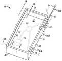
- FIG. 1Ais a perspective view of the presently described sleeve
- FIG. 1Bis a partial sectional side view of the sleeve taken from cutting plane 1 B- 1 B and additionally showing a portion of a nested cell phone within the sleeve.
- FIG. 2is a sectional view taken from cutting plane 2 - 2 in FIG. 1 showing a portion of a nested cell phone above a portion of the sleeve;
- FIG. 3is a partial plan view of the upper right corner of the sleeve of FIG. 1 showing an embodiment having a recess in the side wall wherein an antenna is stored;
- FIG. 4is an electrical schematic diagram of the sleeve and the cell phone showing and electrical interconnection whereby the cell phone battery provides power to an amplifier in the sleeve circuit;
- FIG. 5is a sectional view taken from cutting plane 5 , 6 - 5 , 6 showing a first molding step in embedding a probe and signal transmission conductor within the bottom panel of the sleeve;
- FIG. 6is the sectional view of FIG. 5 showing a second molding step in embedding a probe and signal transmission conductor within the bottom panel of the sleeve.
- FIG. 1Aillustrates a re-radiating cell phone sleeve assembly 10 , referred to herein as sleeve 10 , capable of conforming to, and nesting with, a cell phone 20 or similar portable wireless device which is not a part of sleeve 10 .
- the term cell phone 20is used throughout this description and it should be recognized that this term may refer to a cellular telephone or any other portable RF communication apparatus and sleeve 10 may be fabricated to dimensions that will accept each different size cell phone 20 .
- Sleeve 10includes a full or partial enclosure 30 made of a conformable material such as rubber, rubberized plastic, a plastic and rubber combination, or a combination of plastic polymers.
- Enclosure 30is capable of tightly fitting over and around at least a portion of cell phone 20 against which cell phone 20 will contact and rest when nested with sleeve 10 .
- enclosure 30has a bottom panel 32 integral with a surrounding side wall 34 which has an internal lip flange 36 all around.
- the lip flange 36extends over a portion of a face 22 of cell phone 20 so as to secure cell phone 20 within sleeve 10 as best shown in FIG. 1B .
- the material of which enclosure 30 is fabricatedmay have an elasticity characteristic so that it may be stretched slightly to nest with cell phone 20 and therefore sleeve 10 is held on cell phone 20 by elastic compression. This prevents movement of cell phone 20 within sleeve 10 .
- a planar multi-layer radio frequency (RF) coupling probe 40is embedded within the enclosure 30 by insertion injection molding in a location that is in close proximity to, and may lay directly under, an internal antenna 50 of the cell phone 20 when it is nested. In this manner, the probe 40 is in a position for electromagnetic coupling with antenna 50 and therefore is able to provide for boosting of the cell phone's signals. Inductive, capacitive or other types of electromagnetic coupling may be used.
- a second patterned metallization layer 45 of copper, silver-filled paste or other metal having similar propertieswhich is deposited or printed on one side of
- Probe 40may be square or rectangular in shape with sides of between about 0.25 to 0.30 inches in length.
- An important characteristic of probe 40is that it functions as an anti-resonant network because of its high capacitance-to-inductance ratio which enables near field coupling and may be reception band selective by virtue of its unloaded high-Q quality factor.
- a band selectivity enablementmay provide multi-band resonance, for example, resonance for one or more frequency bands such as: 700, 850, 900, 1800, 1900, and 2100 MHz and, or others.
- An external antenna 60as shown in FIGS. 1A , 3 , and 6 may be mounted on and in parallel alignment with the surrounding side wall 34 as shown in FIG. 1 , and a transmission line 42 embedded within the bottom panel 32 may join probe 40 with external antenna 60 for RF signal transfer therebetween.
- Transmission line 42may be a metallized or printed strip. This arrangement enables RF transmission/reception at both the antennas 50 and 60 simultaneously without experiencing mutual interference.
- Antenna 60may be mounted on enclosure 30 using a mechanical swivel joint 62 so that antenna 60 is able to be rotated between a retracted position 60 A, shown in dashed line in FIG. 1A , and an extended position 60 B.
- Antenna 60may be of any type including a simple rigid rod, or telescoping.
- Side wall 34may have a recess 36 as shown in FIG. 3 for enclosing antenna 60 when retracted, for more compact storage.
- the antenna 60may be operational in both its retracted position 60 A as well as its extended position 60 B.
- Enclosure 30provides a hand grip surface 38 which is positioned so as to leave clearance between antenna 60 when in the refracted position 60 A and a user's hand when holding sleeve assembly 10 .
- Enclosure 30may have a remote antenna port 70 , a connector, molded into side wall 34 as shown in FIG. 1A .
- a toggle switch 72may also be molded into side wall 34 , also shown in FIG. 1A .
- Switch 72may function to select either external antenna 60 or remote antenna 80 as illustrated in FIG. 4 .
- Port 70may be in signal communication with probe 40 via a further conductor 74 embedded in bottom panel 32 .
- An signal boosting amplifier 90may be embedded in bottom panel 32 and interconnected with transmission line 42 .
- Amplifier 90may be single or bi-directional and may be enabled with diplexers, duplexers and automatic gain control (AGC) and other features for improved performance as would be known by those of skill in the art.
- Amplifier 90preferably a planar device, may be powered by a replaceable battery 92 mounted in side wall 34 , and in electrical interconnection therewith by a further embedded conductor (not shown).
- the cell phone's battery 95may be interconnected with amplifier 90 via an interconnecting wire as shown in FIG. 4 . Interconnection may be via an interconnecting conductor with plug termination 94 which may conform, for instance, to the Universal Standard Bus (USB) protocol or otherwise.
- USBUniversal Standard Bus
- the sleeve 10 taken by itselfdefines one embodiment of the present apparatus.
- the sleeve 10 as nested with cell phone 20defines a second embodiment.
- the enclosure 30may be fabricated by injection molding techniques.
- a first molding stepfabricates a first layer 32 A of the bottom panel 32 and an outside portion of the side wall 34 on at least one side as shown in FIG. 5 .
- This first stepwhen completed, is shown as a section view in FIG. 5 .
- Step twoincludes placement of layer 46 in a selected position on the first molded layer 32 A of the bottom panel 32 and then metallizing or printing layer 45 on top of layer 46 , and also transmission line strip 42 , and potentially other interconnecting conductors at the same time.
- the conductive layersmay extend without breaks to the side wall 34 as shown. This, of course, is accomplished by initially masking off the surfaces that do not receive the metal deposition.
- layer 46is placed in intimate contact with layer 45 and then the partially completed enclosure 30 is placed into an injection molding cavity configured to inject a second layer of resin 34 B over the previously formed first layer 32 A. thereby completing bottom panel 32 as well as the inside of the side wall 34 .
- probe 40 and the interconnections to antenna 60 , port 70 and switch 72are fully encapsulated or embedded within bottom panel 32 and side wall 34 .
Landscapes
- Engineering & Computer Science (AREA)
- Computer Networks & Wireless Communication (AREA)
- Signal Processing (AREA)
- Support Of Aerials (AREA)
Abstract
Description
Claims (12)
Priority Applications (13)
| Application Number | Priority Date | Filing Date | Title |
|---|---|---|---|
| US13/238,894US8248314B2 (en) | 2010-09-22 | 2011-09-21 | Inductively coupled signal booster for a wireless communication device and in combination therewith |
| US13/590,053US8519885B2 (en) | 2011-09-21 | 2012-08-20 | Combination hand-held phone and radar system |
| US13/591,152US8559869B2 (en) | 2011-09-21 | 2012-08-21 | Smart channel selective repeater |
| US13/591,171US8560029B2 (en) | 2011-09-21 | 2012-08-21 | Isolation enhancement between planar antenna elements |
| HK15101678.0AHK1201381A1 (en) | 2011-09-21 | 2012-09-21 | Sleeve with electronic extensions for a cell phone |
| CN201280056915.3ACN103988366B (en) | 2011-09-21 | 2012-09-21 | Sleeve with electronic extensions for cell phone |
| MX2014003443AMX2014003443A (en) | 2011-09-21 | 2012-09-21 | Sleeve with electronic extensions for a cell phone. |
| EP12833478.6AEP2759022A4 (en) | 2011-09-21 | 2012-09-21 | PROTECTIVE SHEATH WITH ELECTRONIC EXTENSIONS FOR A CELLULAR TELEPHONE |
| PCT/US2012/056708WO2013044131A1 (en) | 2011-09-21 | 2012-09-21 | Sleeve with electronic extensions for a cell phone |
| KR1020147010438AKR20140069197A (en) | 2011-09-21 | 2012-09-21 | Sleeve with electronic extensions for a cell phone |
| JP2014532033AJP2014532332A (en) | 2011-09-21 | 2012-09-21 | assembly |
| US14/216,985US9124679B2 (en) | 2010-09-22 | 2014-03-17 | Sleeve with electronic extensions for a cell phone |
| US14/726,509US9832295B2 (en) | 2010-09-22 | 2015-05-30 | Sleeve with electronic extensions for a cell phone |
Applications Claiming Priority (2)
| Application Number | Priority Date | Filing Date | Title |
|---|---|---|---|
| US38538610P | 2010-09-22 | 2010-09-22 | |
| US13/238,894US8248314B2 (en) | 2010-09-22 | 2011-09-21 | Inductively coupled signal booster for a wireless communication device and in combination therewith |
Related Parent Applications (3)
| Application Number | Title | Priority Date | Filing Date |
|---|---|---|---|
| US13/238,894Continuation-In-PartUS8248314B2 (en) | 2010-09-22 | 2011-09-21 | Inductively coupled signal booster for a wireless communication device and in combination therewith |
| US13/590,053Continuation-In-PartUS8519885B2 (en) | 2010-09-22 | 2012-08-20 | Combination hand-held phone and radar system |
| US13/591,152Continuation-In-PartUS8559869B2 (en) | 2010-09-22 | 2012-08-21 | Smart channel selective repeater |
Related Child Applications (5)
| Application Number | Title | Priority Date | Filing Date |
|---|---|---|---|
| US13/238,894Continuation-In-PartUS8248314B2 (en) | 2010-09-22 | 2011-09-21 | Inductively coupled signal booster for a wireless communication device and in combination therewith |
| US13/590,053Continuation-In-PartUS8519885B2 (en) | 2010-09-22 | 2012-08-20 | Combination hand-held phone and radar system |
| US13/590,053ContinuationUS8519885B2 (en) | 2010-09-22 | 2012-08-20 | Combination hand-held phone and radar system |
| US13/591,152Continuation-In-PartUS8559869B2 (en) | 2010-09-22 | 2012-08-21 | Smart channel selective repeater |
| US13/591,171Continuation-In-PartUS8560029B2 (en) | 2010-09-22 | 2012-08-21 | Isolation enhancement between planar antenna elements |
Publications (2)
| Publication Number | Publication Date |
|---|---|
| US20120071214A1 US20120071214A1 (en) | 2012-03-22 |
| US8248314B2true US8248314B2 (en) | 2012-08-21 |
Family
ID=45818213
Family Applications (1)
| Application Number | Title | Priority Date | Filing Date |
|---|---|---|---|
| US13/238,894ActiveUS8248314B2 (en) | 2010-09-22 | 2011-09-21 | Inductively coupled signal booster for a wireless communication device and in combination therewith |
Country Status (1)
| Country | Link |
|---|---|
| US (1) | US8248314B2 (en) |
Cited By (5)
| Publication number | Priority date | Publication date | Assignee | Title |
|---|---|---|---|---|
| US9124679B2 (en) | 2010-09-22 | 2015-09-01 | Mojoose, Inc. | Sleeve with electronic extensions for a cell phone |
| US10171133B1 (en) | 2018-02-20 | 2019-01-01 | Automated Assembly Corporation | Transponder arrangement |
| US10169697B1 (en) | 2017-08-30 | 2019-01-01 | Automated Assembly Corporation | Radio frequency tag having integrated and supplemental antenna elements |
| US10849245B2 (en) | 2002-10-22 | 2020-11-24 | Atd Ventures, Llc | Systems and methods for providing a robust computer processing unit |
| US11057130B2 (en) | 2017-01-02 | 2021-07-06 | Mojoose, Inc. | Automatic signal strength indicator and automatic antenna switch |
Families Citing this family (48)
| Publication number | Priority date | Publication date | Assignee | Title |
|---|---|---|---|---|
| AU2003285949A1 (en) | 2002-10-22 | 2004-05-13 | Isys Technologies | Non-peripherals processing control module having improved heat dissipating properties |
| BR0315613A (en) | 2002-10-22 | 2005-08-23 | Jason A Sullivan | Systems and methods for providing a dynamically modular processing unit |
| US8367235B2 (en) | 2008-01-18 | 2013-02-05 | Mophie, Inc. | Battery pack, holster, and extendible processing and interface platform for mobile devices |
| US9123935B2 (en) | 2008-01-18 | 2015-09-01 | Mophie, Inc. | Wireless communication accessory for a mobile device |
| US7782610B2 (en) | 2008-11-17 | 2010-08-24 | Incase Designs Corp. | Portable electronic device case with battery |
| EP2572395A4 (en) | 2010-05-19 | 2014-07-23 | Mophie Inc | MODULAR MOBILE ACCESSORY FOR MOBILE DEVICE |
| US20120206303A1 (en)* | 2010-11-11 | 2012-08-16 | Ethertronics, Inc | Antenna system coupled to an external device |
| US10396451B2 (en) | 2010-11-22 | 2019-08-27 | Ncap Licensing, Llc | Techniques for patch antenna |
| US9088071B2 (en) | 2010-11-22 | 2015-07-21 | ChamTech Technologies, Incorporated | Techniques for conductive particle based material used for at least one of propagation, emission and absorption of electromagnetic radiation |
| WO2012109393A1 (en) | 2011-02-08 | 2012-08-16 | Henry Cooper | High gain frequency step horn antenna |
| WO2012109498A1 (en) | 2011-02-09 | 2012-08-16 | Henry Cooper | Corrugated horn antenna with enhanced frequency range |
| USD718289S1 (en) | 2011-11-11 | 2014-11-25 | Mophie, Inc. | Multi-piece case |
| US8991704B2 (en)* | 2011-12-14 | 2015-03-31 | Intermec Ip Corp. | Snap-on module for selectively installing receiving element(s) to a mobile device |
| US20130237294A1 (en)* | 2012-03-09 | 2013-09-12 | Research In Motion Limited | Auxiliary Antenna Array Attachment for Wireless Devices |
| USD721685S1 (en) | 2012-05-25 | 2015-01-27 | Mophie, Inc. | Mobile phone case |
| USD721356S1 (en) | 2012-05-25 | 2015-01-20 | Mophie, Inc. | Mobile phone case |
| WO2014011943A1 (en)* | 2012-07-11 | 2014-01-16 | Wireless Research Development | Performance enhancing electronic steerable case antenna employing direct or wireless coupling |
| USD727883S1 (en) | 2012-07-20 | 2015-04-28 | Mophie, Inc. | Mobile phone case |
| WO2014036248A1 (en)* | 2012-09-01 | 2014-03-06 | Mophie, Inc. | Wireless communication accessory for a mobile device |
| USD723530S1 (en) | 2012-10-03 | 2015-03-03 | Mophie, Inc. | Unbanded battery case for a mobile device |
| USD721687S1 (en) | 2012-10-30 | 2015-01-27 | Mophie, Inc. | High capacity banded battery case for a mobile device |
| USD718754S1 (en) | 2012-10-30 | 2014-12-02 | Mophie, Inc. | Thin banded battery case for a mobile device |
| USD718293S1 (en) | 2012-11-30 | 2014-11-25 | Mophie, Inc. | Unbanded snap battery case for a mobile device |
| USD718230S1 (en) | 2012-12-04 | 2014-11-25 | Mophie, Inc. | High capacity banded snap battery case for a mobile device |
| USD718755S1 (en) | 2012-12-18 | 2014-12-02 | Mophie, Inc. | Thin banded snap battery case for a mobile device |
| US9755444B2 (en) | 2013-02-25 | 2017-09-05 | Mophie, Inc. | Protective case with switch cover |
| EP2779671B1 (en) | 2013-03-11 | 2017-12-13 | Nagravision S.A. | Electronic support allowing access to remote audio/video assets |
| WO2014150555A1 (en) | 2013-03-15 | 2014-09-25 | Mophie, Inc. | Protective case for mobile device |
| USD732012S1 (en) | 2013-04-06 | 2015-06-16 | Mophie, Inc. | Curved battery case for a mobile device |
| US9450309B2 (en) | 2013-05-30 | 2016-09-20 | Xi3 | Lobe antenna |
| KR102128272B1 (en)* | 2013-11-27 | 2020-06-30 | 삼성전자 주식회사 | Cover for portable electronic device |
| WO2015081125A1 (en) | 2013-11-27 | 2015-06-04 | Mophie, Inc. | Battery pack with supplemental memory |
| KR20160002070A (en)* | 2014-06-30 | 2016-01-07 | 엘지이노텍 주식회사 | Case apparatus |
| US10033204B2 (en) | 2014-09-03 | 2018-07-24 | Mophie, Inc. | Systems and methods for battery charging and management |
| USD797092S1 (en) | 2014-11-25 | 2017-09-12 | Mophie, Inc. | Case for a mobile electronic device |
| USD797091S1 (en) | 2014-11-25 | 2017-09-12 | Mophie, Inc. | Case for a mobile electronic device |
| USD797093S1 (en) | 2014-12-03 | 2017-09-12 | Mophie, Inc. | Case for a mobile electronic device |
| EP3032836A1 (en)* | 2014-12-12 | 2016-06-15 | SmarDTV S.A. | A system for providing access to conditional access media content |
| US9356267B1 (en) | 2014-12-17 | 2016-05-31 | Mophie, Inc. | Protective battery case to partially enclose a mobile electronic device |
| CN106415926B (en)* | 2014-12-30 | 2021-01-05 | 华为技术有限公司 | Antenna device and terminal |
| WO2016159828A1 (en)* | 2015-04-01 | 2016-10-06 | Максим Валерьевич ФЕДОРОВ | Passive rf signal amplifier |
| USD766819S1 (en) | 2015-04-06 | 2016-09-20 | Mophie, Inc. | Protective battery case |
| USD767485S1 (en) | 2015-04-07 | 2016-09-27 | Mophie, Inc. | Battery case |
| USD861653S1 (en) | 2015-05-27 | 2019-10-01 | Mophie Inc. | Protective battery case for mobile communications device |
| USD950538S1 (en)* | 2016-03-03 | 2022-05-03 | Mophie Inc. | Case for a mobile electronic device |
| US10516431B2 (en) | 2017-11-21 | 2019-12-24 | Mophie Inc. | Mobile device case for receiving wireless signals |
| CN211182516U (en)* | 2020-03-24 | 2020-08-04 | 京东方科技集团股份有限公司 | Electronic pen motherboard and electronic pen |
| CN113552539B (en)* | 2021-06-22 | 2024-06-04 | 珠海市海米软件技术有限公司 | Resonant electromagnetic decoupling component for improving millimeter wave radar receiving and transmitting isolation |
Citations (25)
| Publication number | Priority date | Publication date | Assignee | Title |
|---|---|---|---|---|
| US5170494A (en) | 1988-12-08 | 1992-12-08 | Nokia Mobile Phones Ltd. | Two piece radio telephone |
| US5532703A (en) | 1993-04-22 | 1996-07-02 | Valor Enterprises, Inc. | Antenna coupler for portable cellular telephones |
| US5673053A (en) | 1993-09-06 | 1997-09-30 | Allgon Ab | Antenna coupling device for coupling an antenna of a hand-portable telephone to a remotely located antenna |
| US5854970A (en) | 1996-10-08 | 1998-12-29 | Nokia Mobile Phones Limited | Accessory RF unit for hand-held wireless telephone systems |
| US6061028A (en)* | 1996-11-25 | 2000-05-09 | Musou Co., Ltd. | Plane antenna system for mobile communication equipment |
| US6111545A (en) | 1992-01-23 | 2000-08-29 | Nokia Mobile Phones, Ltd. | Antenna |
| US6112106A (en) | 1993-04-05 | 2000-08-29 | Crowley; Robert J. | Antenna transmission coupling arrangement |
| US6281854B1 (en)* | 1999-05-28 | 2001-08-28 | Denso Corporation | Antenna for portable radio device |
| US6317089B1 (en) | 1999-12-23 | 2001-11-13 | Wilson Electronics, Inc. | Hand-held transceiver antenna system |
| US6380623B1 (en)* | 1999-10-15 | 2002-04-30 | Hughes Electronics Corporation | Microcircuit assembly having dual-path grounding and negative self-bias |
| US6459915B2 (en) | 1997-09-02 | 2002-10-01 | Matsushita Electric Industrial Co. Ltd. | External adapter for a portable cellular phone |
| US6492952B1 (en) | 1999-11-17 | 2002-12-10 | Allgon, Ab | Antenna device, a communication device including such an antenna device and a method of operating the communication device |
| US6538620B2 (en)* | 2001-07-09 | 2003-03-25 | Susan Lin | Safe sticker antenna for mobile phones |
| US6924769B2 (en) | 2001-12-27 | 2005-08-02 | Matsushita Electric Industrial Co., Ltd. | Antenna for communication terminal apparatus |
| JP2006148751A (en) | 2004-11-24 | 2006-06-08 | Dx Antenna Co Ltd | External antenna extending device |
| US7081857B2 (en) | 2002-12-02 | 2006-07-25 | Lk Products Oy | Arrangement for connecting additional antenna to radio device |
| US7084819B2 (en)* | 2002-12-19 | 2006-08-01 | De La Torre Barreiro Jose Luis | Passive reflector for a mobile communication device |
| US7218280B2 (en)* | 2004-04-26 | 2007-05-15 | Pulse Finland Oy | Antenna element and a method for manufacturing the same |
| US7231236B2 (en) | 2003-08-01 | 2007-06-12 | Samsung Techwin Co., Ltd. | Integrated antenna and input/output port for a wireless communication device |
| US7405698B2 (en)* | 2004-10-01 | 2008-07-29 | De Rochemont L Pierre | Ceramic antenna module and methods of manufacture thereof |
| US7427961B2 (en)* | 2005-08-19 | 2008-09-23 | Gm Global Technology Operations, Inc. | Method for improving the efficiency of transparent thin film antennas and antennas made by such method |
| CN201233951Y (en) | 2008-07-08 | 2009-05-06 | 比亚迪股份有限公司 | Mobile phone antenna |
| US7719083B2 (en)* | 1998-11-12 | 2010-05-18 | Broadcomm Corporation | Integrated spiral inductor |
| WO2010098540A2 (en) | 2009-02-25 | 2010-09-02 | 주식회사 에이티앤씨 | Portable terminal case with a built-in internal antenna, and method for manufacturing same |
| US7881693B2 (en)* | 2006-10-17 | 2011-02-01 | Semiconductor Energy Laboratory Co., Ltd. | Semiconductor device |
- 2011
- 2011-09-21USUS13/238,894patent/US8248314B2/enactiveActive
Patent Citations (25)
| Publication number | Priority date | Publication date | Assignee | Title |
|---|---|---|---|---|
| US5170494A (en) | 1988-12-08 | 1992-12-08 | Nokia Mobile Phones Ltd. | Two piece radio telephone |
| US6111545A (en) | 1992-01-23 | 2000-08-29 | Nokia Mobile Phones, Ltd. | Antenna |
| US6112106A (en) | 1993-04-05 | 2000-08-29 | Crowley; Robert J. | Antenna transmission coupling arrangement |
| US5532703A (en) | 1993-04-22 | 1996-07-02 | Valor Enterprises, Inc. | Antenna coupler for portable cellular telephones |
| US5673053A (en) | 1993-09-06 | 1997-09-30 | Allgon Ab | Antenna coupling device for coupling an antenna of a hand-portable telephone to a remotely located antenna |
| US5854970A (en) | 1996-10-08 | 1998-12-29 | Nokia Mobile Phones Limited | Accessory RF unit for hand-held wireless telephone systems |
| US6061028A (en)* | 1996-11-25 | 2000-05-09 | Musou Co., Ltd. | Plane antenna system for mobile communication equipment |
| US6459915B2 (en) | 1997-09-02 | 2002-10-01 | Matsushita Electric Industrial Co. Ltd. | External adapter for a portable cellular phone |
| US7719083B2 (en)* | 1998-11-12 | 2010-05-18 | Broadcomm Corporation | Integrated spiral inductor |
| US6281854B1 (en)* | 1999-05-28 | 2001-08-28 | Denso Corporation | Antenna for portable radio device |
| US6380623B1 (en)* | 1999-10-15 | 2002-04-30 | Hughes Electronics Corporation | Microcircuit assembly having dual-path grounding and negative self-bias |
| US6492952B1 (en) | 1999-11-17 | 2002-12-10 | Allgon, Ab | Antenna device, a communication device including such an antenna device and a method of operating the communication device |
| US6317089B1 (en) | 1999-12-23 | 2001-11-13 | Wilson Electronics, Inc. | Hand-held transceiver antenna system |
| US6538620B2 (en)* | 2001-07-09 | 2003-03-25 | Susan Lin | Safe sticker antenna for mobile phones |
| US6924769B2 (en) | 2001-12-27 | 2005-08-02 | Matsushita Electric Industrial Co., Ltd. | Antenna for communication terminal apparatus |
| US7081857B2 (en) | 2002-12-02 | 2006-07-25 | Lk Products Oy | Arrangement for connecting additional antenna to radio device |
| US7084819B2 (en)* | 2002-12-19 | 2006-08-01 | De La Torre Barreiro Jose Luis | Passive reflector for a mobile communication device |
| US7231236B2 (en) | 2003-08-01 | 2007-06-12 | Samsung Techwin Co., Ltd. | Integrated antenna and input/output port for a wireless communication device |
| US7218280B2 (en)* | 2004-04-26 | 2007-05-15 | Pulse Finland Oy | Antenna element and a method for manufacturing the same |
| US7405698B2 (en)* | 2004-10-01 | 2008-07-29 | De Rochemont L Pierre | Ceramic antenna module and methods of manufacture thereof |
| JP2006148751A (en) | 2004-11-24 | 2006-06-08 | Dx Antenna Co Ltd | External antenna extending device |
| US7427961B2 (en)* | 2005-08-19 | 2008-09-23 | Gm Global Technology Operations, Inc. | Method for improving the efficiency of transparent thin film antennas and antennas made by such method |
| US7881693B2 (en)* | 2006-10-17 | 2011-02-01 | Semiconductor Energy Laboratory Co., Ltd. | Semiconductor device |
| CN201233951Y (en) | 2008-07-08 | 2009-05-06 | 比亚迪股份有限公司 | Mobile phone antenna |
| WO2010098540A2 (en) | 2009-02-25 | 2010-09-02 | 주식회사 에이티앤씨 | Portable terminal case with a built-in internal antenna, and method for manufacturing same |
Cited By (8)
| Publication number | Priority date | Publication date | Assignee | Title |
|---|---|---|---|---|
| US10849245B2 (en) | 2002-10-22 | 2020-11-24 | Atd Ventures, Llc | Systems and methods for providing a robust computer processing unit |
| US11751350B2 (en) | 2002-10-22 | 2023-09-05 | Atd Ventures, Llc | Systems and methods for providing a robust computer processing unit |
| US9124679B2 (en) | 2010-09-22 | 2015-09-01 | Mojoose, Inc. | Sleeve with electronic extensions for a cell phone |
| US9832295B2 (en) | 2010-09-22 | 2017-11-28 | Mojoose, Inc. | Sleeve with electronic extensions for a cell phone |
| US11057130B2 (en) | 2017-01-02 | 2021-07-06 | Mojoose, Inc. | Automatic signal strength indicator and automatic antenna switch |
| US11843425B2 (en) | 2017-01-02 | 2023-12-12 | Mojoose, Inc. | Automatic signal strength indicator and automatic antenna switch |
| US10169697B1 (en) | 2017-08-30 | 2019-01-01 | Automated Assembly Corporation | Radio frequency tag having integrated and supplemental antenna elements |
| US10171133B1 (en) | 2018-02-20 | 2019-01-01 | Automated Assembly Corporation | Transponder arrangement |
Also Published As
| Publication number | Publication date |
|---|---|
| US20120071214A1 (en) | 2012-03-22 |
Similar Documents
| Publication | Publication Date | Title |
|---|---|---|
| US8248314B2 (en) | Inductively coupled signal booster for a wireless communication device and in combination therewith | |
| US10847876B2 (en) | Antenna system coupled to an external device | |
| CN110875512B (en) | Antenna structure and wireless communication device with same | |
| CN104704585B (en) | Apparatus and method for power harvesting and/or wireless communication | |
| US7825860B2 (en) | Antenna assembly | |
| KR101276650B1 (en) | Antenna device with wireless charging | |
| US9153865B2 (en) | Antenna device and communication terminal apparatus | |
| US20010015705A1 (en) | Slot antenna device | |
| KR101162024B1 (en) | Case having an antenna with an active module and an electronic device having the same | |
| KR101964636B1 (en) | Electronic device | |
| KR20100024421A (en) | Antenna | |
| TW201401708A (en) | Antenna sheet for contactless charging device and charging device using said sheet | |
| EP3817145A1 (en) | Antenna unit, array antenna, and electronic device | |
| US20100090922A1 (en) | Antenna For Mobile Terminal Unit | |
| US9191471B2 (en) | Wireless communication device | |
| JPH09121178A (en) | Portable telephone set and portable telephone system using it | |
| US20180241433A1 (en) | Antenna device for short-range applications and use of an antenna device of this type | |
| CN204497378U (en) | Aerial coil built-in module, antenna assembly and communication equipment | |
| WO2009027111A1 (en) | Electrically conductive casing of a portable communication device as fm antenna | |
| EP3011640A1 (en) | Antenna arrangement and device | |
| EP2608498B1 (en) | Method for using handle rope of fixed wireless telephone as frequency modulation (fm) antenna and fixed wireless telephone | |
| KR101054579B1 (en) | Built-in antenna and manufacturing method of built-in antenna | |
| US9711847B2 (en) | Apparatus and method for integrating a reduced-sized antenna with an accessory connector | |
| CN218472280U (en) | Antenna device and mobile terminal | |
| JP2017069608A (en) | Communication device |
Legal Events
| Date | Code | Title | Description |
|---|---|---|---|
| STCF | Information on status: patent grant | Free format text:PATENTED CASE | |
| AS | Assignment | Owner name:MOBILE JOOSE, INC., CALIFORNIA Free format text:ASSIGNMENT OF ASSIGNORS INTEREST;ASSIGNORS:ASH, DANIEL R., JR., MR.;ASH, DANIEL R., SR., MR.;REEL/FRAME:029332/0943 Effective date:20121119 | |
| AS | Assignment | Owner name:MOBILE JOOSE, INC., CALIFORNIA Free format text:ASSIGNMENT OF ASSIGNORS INTEREST;ASSIGNOR:ASH, DANIEL R., SR.;REEL/FRAME:032459/0979 Effective date:20140224 Owner name:MOBILE JOOSE, INC., CALIFORNIA Free format text:ASSIGNMENT OF ASSIGNORS INTEREST;ASSIGNOR:ASH, DANIEL R., JR.;REEL/FRAME:032458/0085 Effective date:20140221 Owner name:MOJOOSE, INC., CALIFORNIA Free format text:ASSIGNMENT OF ASSIGNORS INTEREST;ASSIGNOR:MOBILE JOOSE, INC.;REEL/FRAME:032458/0031 Effective date:20140317 | |
| FPAY | Fee payment | Year of fee payment:4 | |
| AS | Assignment | Owner name:EUROPLAY CAPITAL ADVISORS, LLC, CALIFORNIA Free format text:SECURITY INTEREST;ASSIGNOR:MOJOOSE, INC.;REEL/FRAME:043119/0281 Effective date:20140313 | |
| CC | Certificate of correction | ||
| FEPP | Fee payment procedure | Free format text:MAINTENANCE FEE REMINDER MAILED (ORIGINAL EVENT CODE: REM.); ENTITY STATUS OF PATENT OWNER: SMALL ENTITY | |
| AS | Assignment | Owner name:MOJOOSE, INC., CALIFORNIA Free format text:RELEASE BY SECURED PARTY;ASSIGNOR:EUROPLAY CAPITAL ADVISORS, LLC;REEL/FRAME:052817/0847 Effective date:20170915 | |
| FEPP | Fee payment procedure | Free format text:7.5 YR SURCHARGE - LATE PMT W/IN 6 MO, SMALL ENTITY (ORIGINAL EVENT CODE: M2555); ENTITY STATUS OF PATENT OWNER: SMALL ENTITY | |
| MAFP | Maintenance fee payment | Free format text:PAYMENT OF MAINTENANCE FEE, 8TH YR, SMALL ENTITY (ORIGINAL EVENT CODE: M2552); ENTITY STATUS OF PATENT OWNER: SMALL ENTITY Year of fee payment:8 | |
| FEPP | Fee payment procedure | Free format text:MAINTENANCE FEE REMINDER MAILED (ORIGINAL EVENT CODE: REM.); ENTITY STATUS OF PATENT OWNER: SMALL ENTITY | |
| FEPP | Fee payment procedure | Free format text:11.5 YR SURCHARGE- LATE PMT W/IN 6 MO, SMALL ENTITY (ORIGINAL EVENT CODE: M2556); ENTITY STATUS OF PATENT OWNER: SMALL ENTITY | |
| MAFP | Maintenance fee payment | Free format text:PAYMENT OF MAINTENANCE FEE, 12TH YR, SMALL ENTITY (ORIGINAL EVENT CODE: M2553); ENTITY STATUS OF PATENT OWNER: SMALL ENTITY Year of fee payment:12 |