US8248075B2 - System, apparatus and method for dissipating standing wave in a microwave delivery system - Google Patents
System, apparatus and method for dissipating standing wave in a microwave delivery systemDownload PDFInfo
- Publication number
- US8248075B2 US8248075B2US12/242,026US24202608AUS8248075B2US 8248075 B2US8248075 B2US 8248075B2US 24202608 AUS24202608 AUS 24202608AUS 8248075 B2US8248075 B2US 8248075B2
- Authority
- US
- United States
- Prior art keywords
- microwave
- microwave energy
- signal
- energy delivery
- transfer switch
- Prior art date
- Legal status (The legal status is an assumption and is not a legal conclusion. Google has not performed a legal analysis and makes no representation as to the accuracy of the status listed.)
- Expired - Fee Related, expires
Links
- 238000000034methodMethods0.000titleclaimsabstractdescription44
- 230000000737periodic effectEffects0.000claimsabstractdescription25
- 238000012546transferMethods0.000claimsdescription112
- 238000005259measurementMethods0.000claimsdescription107
- 238000012360testing methodMethods0.000claimsdescription15
- 230000001052transient effectEffects0.000description27
- 238000002679ablationMethods0.000description20
- 230000007246mechanismEffects0.000description17
- 230000007704transitionEffects0.000description15
- 230000005540biological transmissionEffects0.000description14
- 238000002955isolationMethods0.000description13
- 238000010586diagramMethods0.000description11
- 238000012545processingMethods0.000description9
- 230000002441reversible effectEffects0.000description7
- 238000005070samplingMethods0.000description6
- 230000008859changeEffects0.000description5
- 230000008878couplingEffects0.000description5
- 238000010168coupling processMethods0.000description5
- 238000005859coupling reactionMethods0.000description5
- 230000009977dual effectEffects0.000description5
- 238000004891communicationMethods0.000description4
- 239000004020conductorSubstances0.000description4
- 238000006703hydration reactionMethods0.000description3
- 238000003780insertionMethods0.000description3
- 230000037431insertionEffects0.000description3
- 230000004913activationEffects0.000description2
- 230000009286beneficial effectEffects0.000description2
- 238000010276constructionMethods0.000description2
- 239000012809cooling fluidSubstances0.000description2
- 230000007423decreaseEffects0.000description2
- 238000013461designMethods0.000description2
- 230000036571hydrationEffects0.000description2
- 230000001939inductive effectEffects0.000description2
- 230000000977initiatory effectEffects0.000description2
- 238000011160researchMethods0.000description2
- 230000004044responseEffects0.000description2
- 239000000523sampleSubstances0.000description2
- 230000001225therapeutic effectEffects0.000description2
- 238000011298ablation treatmentMethods0.000description1
- 230000003213activating effectEffects0.000description1
- 230000002238attenuated effectEffects0.000description1
- 238000004364calculation methodMethods0.000description1
- 230000003750conditioning effectEffects0.000description1
- 238000010411cookingMethods0.000description1
- 230000002596correlated effectEffects0.000description1
- 230000001419dependent effectEffects0.000description1
- 238000001514detection methodMethods0.000description1
- 230000005672electromagnetic fieldEffects0.000description1
- 230000001976improved effectEffects0.000description1
- 230000003993interactionEffects0.000description1
- 238000007726management methodMethods0.000description1
- 238000003012network analysisMethods0.000description1
- 238000005457optimizationMethods0.000description1
- 230000010363phase shiftEffects0.000description1
- 238000002360preparation methodMethods0.000description1
- 230000009467reductionEffects0.000description1
Images


Classifications
- A—HUMAN NECESSITIES
- A61—MEDICAL OR VETERINARY SCIENCE; HYGIENE
- A61B—DIAGNOSIS; SURGERY; IDENTIFICATION
- A61B18/00—Surgical instruments, devices or methods for transferring non-mechanical forms of energy to or from the body
- A61B18/18—Surgical instruments, devices or methods for transferring non-mechanical forms of energy to or from the body by applying electromagnetic radiation, e.g. microwaves
- A61B18/1815—Surgical instruments, devices or methods for transferring non-mechanical forms of energy to or from the body by applying electromagnetic radiation, e.g. microwaves using microwaves
Definitions
- the present inventionrelates to systems and methods for performing a medical procedure, wherein the medical procedure includes the generation and transfer of energy from an energy source to a dynamically changing device and, more particularly, efficient transfer of energy through a microwave energy delivery, measurement and control system.
- the electrical performance of a microwave antenna probechanges throughout the course of an ablation treatment.
- the change in performancemay be due to the device or due to changes in tissue properties.
- the ability to observe parameters indicative of changes in antenna property, antenna performance or tissue properties changes during ablationgreatly aids in the understanding of microwave ablation.
- measuring antenna impedanceis a common method for determining antenna performance and/or a change in an antenna property.
- Microwave systemsare typically designed to a characteristic impedance, such as, for example, 50 Ohms, wherein the impedance of the generator, the delivery system, the ablation device and tissue are about equal to the characteristic impedance. Efficiency of energy delivery decreases when the impedance of any portion of the system changes.
- impedanceWith low frequency RF systems impedance can easily be determined by measuring the delivered current at a known voltage and calculating tissue impedance using well known algorithms. Obtaining accurate measurements of tissue impedance at microwave frequencies is more difficult because circuits behave differently at microwave frequency. For example, unlike an electrode in an RF system, an antenna in a microwave system does not conduct current to tissue. In addition, other components in a microwave system may transmit or radiate energy, like an antenna, or components may reflect energy back into the generator. As such, it is difficult to determine what percentage of the energy generated by the microwave generator is actually delivered to tissue, and conventional algorithms for tissue impedance are inaccurate.
- One alternative method of measuring impedance in a microwave energy delivery systemis by determining broadband scattering parameters. Capturing antenna broadband scattering parameters periodically throughout a high power ablation cycle necessitates the use of equipment that requires precise calibration. Unfortunately, this equipment is prone to damage by high power signals and the microwave energy delivery system typically needs to be reconfigured to accommodate and protect such equipment.
- the present disclosuredescribes a Microwave Research Tool (MRT) that includes a system to measure impedance in a microwave energy delivery system by direct and indirect methods including a system to measure broadband scattering parameters.
- MRTMicrowave Research Tool
- a system for dissipating a standing waveincludes a microwave energy source configured to intermittently delivery microwave energy as a periodic microwave signal an energy delivery network configured to transmit the periodic microwave signal and a circuit connected between the microwave energy source and the energy delivery network.
- the circuitis configured to pass the periodic microwave signal from the microwave energy source to the energy delivery network when the periodic microwave signal is present and to dissipate standing waves when the periodic microwave signal is absent.
- the circuitincludes a first resistive load and a circulator configured to direct the periodic microwave signal from the microwave energy source to the energy delivery network.
- the circulatoris also configured to direct energy from the energy delivery network to the first resistive load, the first resistive load connected between the circulator and a ground potential.
- the first resistive loaddissipate energy reflective from the energy delivery network when the periodic microwave signal is in a high energy condition and dissipates residual energy when the periodic microwave signal is in a low energy condition.
- the system for dissipating a standing wavealso includes a microwave energy delivery device, a network analyzer, a second resistive load, connected between the transfer switch and a ground potential, and a transfer switch connected between the circulator, the microwave energy delivery device, the second resistive load and the network analyzer.
- the transfer switchin a first condition, connects the network analyzer to the microwave energy delivery device and the circulator to the second resistive load.
- the transfer switchin a second condition, connects the circulator to the microwave energy delivery device and the network analyzer to the second resistive load.
- the transfer switchelectrically isolates the network analyzer from the microwave energy source.
- the microwave energy delivery deviceis a medical device.
- the first transfer switchin a first condition, passes a testing signal from the network analyzer to the microwave energy delivery device. In a second condition the first transfer switch passes a microwave energy signal from the microwave energy source to the microwave energy delivery device.
- an apparatus for dissipating standing waves in a microwave energy delivery systemincludes a circulator configured to direct a periodic microwave signal from a microwave energy source to the an energy delivery network and configured to direct energy from the energy delivery network to a first resistive load wherein the first resistive load is connected between the circulator and a ground source, the first resistive load further configured to shunt residual energy to ground through the first resistive load.
- the first resistive loaddissipates energy reflective from the energy delivery network when the periodic microwave signal is present and dissipates residual energy in the system when the periodic microwave signal is absent.
- a method of dissipating standing waves in a microwave energy delivery systemincludes the steps of: providing a microwave energy source configured to generate a continuous microwave energy signal; time-proportioning the continuous microwave energy signal between an energy delivery network and a load resistor connected to a ground potential, the energy delivery network configured to intermittently transmit a portion of the continuous microwave energy signal; dissipating reflective energy when the energy delivery network is receiving the microwave energy signal; and dissipating standing waves when the energy delivery network is not receiving the microwave energy signal.
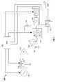
- FIG. 1is a functional block diagram of a microwave energy delivery, measurement and control system in an energy delivery mode according to an embodiment of the present disclosure
- FIG. 2is a state machine functional block diagram of the microwave energy delivery, measurement and control system of FIG. 1 ;
- FIG. 3is a switch control state machine for the microwave energy delivery, measurement and control system including a precision network analyzer
- FIG. 4is a functional block diagram of a precision network analyzer including passive and active measurements
- FIG. 5is a functional block diagram of a microwave energy delivery, measurement and control system including an impedance tuner
- FIG. 6is a switch control state machine for the microwave energy delivery, measurement and control system including a precision network analyzer, CPU and a tuner;
- FIG. 7is a functional block diagram of a microwave energy delivery, measurement and control system according to another embodiment of the present disclosure.
- FIG. 8Ais a schematic representation of an ablation device for use in calibrating the microwave energy delivery, measurement and control system of the present disclosure
- FIG. 8Bis a cross-sectional schematic representation of the ablation device and switching mechanism for calibrating the microwave energy delivery device
- FIG. 8Cis an electrical schematic of the switching mechanism of FIG. 8B ;
- FIG. 9Ais a schematic representation of a stand-alone calibration device for use in calibrating the microwave energy delivery, measurement and control system of the present disclosure.
- FIG. 9Bis a schematic representation of a interfacing calibration device for use in calibrating the microwave energy delivery, management and control system of the present disclosure.
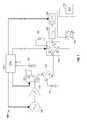
- MRT 100a Microwave Research Tool including a measurement and control system for use in performing a medical procedure or medical procedure testing, employing embodiments of the present disclosure is generally designated 100 .
- MRT 100may provide all the functionality of a microwave generator typically used to deliver microwave energy in a medical procedure but with improved functionality as described herewithin.
- MRT 100includes individual components, as illustrated in FIG. 1 , or the functionality of individual components may be combined or included in one or more components. Components are interconnected with suitable cables and/or connectors.
- MRT 100includes a microwave energy delivery system, a measurement system and a supervisory control system. Each system is described individually although each system may share common components as discussed hereinbelow.
- the microwave energy delivery systemincludes a signal generator 105 capable of generating and supplying a high frequency microwave signal to an amplifier 110 .
- Signal generator 105may be a single frequency generator or may include variable frequency capability.
- Signal generator 105may also be capable of providing a signal including two or more frequencies wherein the device under test 115 (DUT) resonates at two or more frequencies.
- Supervisory control systemmay control various aspects of the signal generator 105 such as, for example, the signal delivery timing, the frequency (or frequencies) of the output and the phase of the signal.
- Amplifier 110receives and amplifies the signal from the signal generator 105 to a desirable energy level.
- Amplifier 110may be a single or multi-stage amplifier 110 and may include one or more signal conditioning circuits or filters (not shown) such as, for example, a low, high or bandpass circuits.
- Amplifier 110 gainmay be fixed or controlled by a suitable controller, such as, for example, a control algorithm in the supervisory control system, a central processing unit 120 (CPU) or by manual adjustment (not shown).
- Hot switch relay 125is controlled by the supervisory control system or CPU 120 and switches the amplified microwave signal to one of an amplifier burn-off load resistor 130 and a circulator 135 .
- the hot switch relay 125 in Position Adelivers energy to the DUT 115 through the circulator 135 .
- the hot switch relay 125 in Position Bdelivers energy away from the DUT 115 and into an amplifier burn-off load resistor 130 .
- Hot switch relay 125may be any suitable solid-state high power switch capable of switching a high power microwave energy signal. Hot switch relay 125 receives the high power microwave signal from the signal generator 105 and amplifier 110 , and passes the signal between the amplifier burn-off load resistor 130 or the circulator 135 without powering down the signal generator 105 or amplifier 110 .
- One suitable deviceis a JFW 50S-1552-N, which is a 150 watt 915 MHz dual pole single-throw solid-state switch that can be powered by two DC supply lines and controlled with a single TTL signal line from a supervisory control system or CPU 120 .
- the JFW 50S-1552-Nallows the MRT 100 to provide near instantaneous power (i.e. can provide nearly continuous power with very rapid on/off capabilities) without creating amplifier transients, by eliminating the need to power down the signal generator 105 or amplifier 110 .
- the MRTmay provide two sources of electrical isolation between the microwave energy signal and the measurement devices.
- the first source of electrical isolationmay be provided by the electrical isolation in the hot switch relay 125 between the output of Position A and the output of Position B. This electrical isolation prevents unacceptable amounts of energy from the high power microwave energy signal from being passed to the Position A output and to the measurement system connected thereto.
- the JFW 50S-1552-N switch(discussed above) provides about 45 dB of electrical isolation between outputs.
- the second source of electrical isolationis provided by the transfer switch 140 and the electrical isolation between Port 4 and Port 2 of the transfer switch 140 discussed hereinbelow.
- the switching time between Positions A and B on the hot switch relay 125should be sufficiently fast to allow continuous operation of the signal generator 105 and amplifier 110 .
- the JFW 50S-1552-Nswitches between Position A and B in about 360 ns and between Positions B and A in about 370 ns.
- Amplifier burn-off load resistor 130may be any suitable coaxial terminator capable of dissipating microwave energy while generating a minimal amount of VSWR, or reflective energy, over the bandwidth of the signal generator 105 .
- One such deviceis a 1433-3 50-ohm 250-watt coaxial terminator sold by Aeroflex/Weinschel and intended for operation over the bandwidth of DC to 5 GHz. Over the entire bandwidth of the 1433-3 the VSWR is less than 1.1.
- Circulator 135is a passive three port device that eliminates standing waves between the hot switch relay 125 and the transfer switch 140 .
- Circulator 135passes signals received on Port A to Port B, signals received on Port B to Port C and signals received on Port C to Port A.
- the microwave energy signalis passed from Port A of the circulator 135 to the transfer switch 140 connected to Port B.
- Reflected energy from the transfer switch 140 or the DUT 115 , received on Port Bis passed to Port C and dissipated through the reflected energy burn-off load resistor 142 .
- Reflected energy burn-off load resistor 142is similar in function to the amplifier burn-off load resistor 130 as discussed hereinabove.
- Hot switch relay 125 and transfer switch 140when switching from Positions A to Positions B, appears as open circuits to the circulator 135 .
- the circulator 135clears the system of any residual power left in the system by directing the residual power into the reflected energy burn-off load resistor 142 .
- hot switch relay 125switches from Position A to Position B energy from dual directional coupler 145 and the DUT 115 is directed through the transfer switch 140 , to the circulator 135 and is dissipated by the reflected energy burn-off load resistor 142 .
- the MRT 100connects to the DUT 115 and performs active measurements thereof. Interaction between the hot switch relay 125 , the transfer switch 140 and active testing of the DUT 115 is further described hereinbelow.
- Transfer switch 140provides sufficient electrical isolation between the measurement system and the microwave energy delivery system.
- Position Athe high power microwave energy signal is received on Port 4 , Port passed to Port 3 and to the directional coupler 145 .
- the precision network analyzer 150connected to Port 2 of the transfer switch 140 , connects the transfer switch load resistor 155 on Port 1 .
- Port In Position Benergy received on Port 4 is passed to Port 1 and dissipated by the transfer switch load resistor 155 , and the precision network analyzer 150 on Port 2 is connected to through Port 3 to the directional coupler 145 and the DUT 115 .
- the transfer switch 140maintains electrical isolation between Ports 4 and 2 (and electrical isolation between the high power microwave energy and the precision network analyzer 150 ) regardless of the transfer switch 140 position.
- microwave energyis switched to the amplifier burn-off load resistor 130 by the hot switch relay 125 before the transfer switch 140 switches from Position A to Position B.
- the transfer switch 140does not operate as a “hot switch” because it is not under a load from the signal generator 105 or amplifier 110 when switching occurs.
- TNH1D31 coaxial transfer switchsold by Ducommun of Carson Calif.
- the TNH1D31displays less than 1.05 VSWR, better than 0.1 dB insertion loss and less than 80 dB electrical isolation for all states at 915 MHz.
- the hot switch relay 125switches out the high energy microwave energy signal before the transfer switch 140 transitions, therefore, transition times for the transfer switch 140 are not critical. High-to-low transition times for the TNDH1D31 are about 75 ms and low-to-high transitions times are about 25 ms.
- Directional coupler 145may be configured to operate like most conventional directional couplers known in the available art. As illustrated in FIG. 1 , directional coupler 145 passes the high power microwave energy signal received on Port 1 to Port 2 with minimal insertion loss. Energy reflected back from the DUT 115 and received on Port 2 of the directional coupler 145 is passed through the transfer switch 140 to Port B of the circulator 135 . Energy received from the transfer switch 140 on Port B of the circulator 135 is passed to Port C of the circulator 135 and dissipated by the reflected energy burn-off load resistor 142 .
- Directional coupler 145samples a small portion of each of the signals received on Port 1 and Port 2 and passes a small portion of the signals to Ports 3 and 4 , Port respectively.
- the signals on Port 3 and 4are proportional to the forward and reverse power, respectively.
- the measurement systemmeasures the signal samples and provides the measurements to the supervisory control system.
- Directional coupler 145samples a small portion of each of the signals received on Port 1 and Port 2 and passes a small portion of the signals to Ports 3 and 4 , Port respectively.
- the signals on Port 3 and 4are proportional to the forward and reverse power, respectively.
- the measurement systemmeasures the signal samples and provides the measurements to the CPU 120 .
- the forward and reverse power measurements from the directional coupler 145are passively measured and the samples may be taken continuously or at a periodic sample frequency.
- the directional coupler 145 measurementsare indirect measurements of the delivered energy. As such, the measurements from the directional coupler 145 are limited to the bandwidth of the microwave energy supplied to the ablation device 115 from the signal generator 100 (i.e., feedback is fixed to the frequency of the high power microwave energy signal).
- a single frequency measurements, or narrowband measurementcan be used to calibrate amplitude and phase at a single frequency.
- calibrating and/or compensating for the return loss to the antenna feedpoint and phase for ‘open’ or ‘short’we are able to obtain a characteristic representation of the antenna's behavior (i.e., a Smith Chart representation of the antenna behavior).
- One suitable directional coupler 145is a directional coupler sold by Werlatone of Brewster, N.Y.
- the directional coupler 145may be a 40 dB dual directional coupler with 30 dB directivity and less than 0.1 dB insertion loss from 800 MHz to 3 GHz.
- DUT 115includes a microwave ablation device that connects to Port 2 of the directional coupler 145 and may be any suitable microwave device capable of delivering microwave energy to tissue. DUT 115 may also include the tissue or surrounding medium in which the microwave ablation device is inserted or deployed.
- Supervisory control systemincludes a central processor unit 120 (CPU) capable of executing instructions and/or performing algorithms, configured to receive one or more inputs and may be configured to control one or more devices in the MRT 100 .
- Inputsmay include analog inputs, such as, for example, signals from the forward and reverse coupling ports, Port 3 and Port 4 of the directional coupler 145 , respectively.
- Inputsmay also include digital inputs, such as, for example, communication with one or more devices (i.e., precision network analyzer 150 ).
- CPU 120may control one or more components of the MRT 100 .
- the signal generator 105may receive at least one of an enabled/disabled control signal from the CPU 120 and reference signal.
- Enable/disable control signalindicates that the MRT system is in a condition to receive a microwave signal (i.e., the hot switch relay 125 and/or the transfer switch 140 are in a suitable position to receive a microwave signal).
- Reference signalsmay include the desired microwave frequency and a gain setting.
- CPU 120may also provide control signals to the precision network analyzer 150 .
- the functionality of the measurement systemmay be performed in the CPU 120 and the precision network analyzer 150 .
- the CPU 120receives the passive inputs of power measurements (i.e., forward and reflected power signals from the directional coupler 145 ) and the precision network analyzer 150 performs active measurements of the DUT 115 .
- the measurement systemmay include other inputs, such as, for example, temperature sensors, cooling fluid temperature or flow sensors, movement sensors, power sensors, or electromagnetic field sensors.
- an array of temperature sensors(not shown) configured to measure tissue temperature surrounding the DUT may be connected to the CPU 120 or the precision network analyzer 150 .
- Tissue temperaturesmay be used to generate an estimation of an ablation size or to generate an alarm or fault condition.
- Cooling fluid temperature or flow sensorsmay be used to indicate proper operation of a cooled DUT 115 .
- the CPU 120 or precision network analyzer 150may include all of the functionality of the supervisory control system, measurement system or any combination thereof.
- the precision network analyzer 150may receive the passive inputs, performs the active measurements and then report information to the supervisory system.
- the precision network analyzer 150is part of a modular system, such as, for example, a PXI system (PCI extensions for Instrumentation) fold by National Instrument of Austin, Tex.
- a PXI system(not shown) may include a chassis configured to house a plurality of functional components that form the MRT 100 and connect over a CPI backplane, across a PCI bridge or by any other suitable connection.
- Precision network analyzer 150 of the measurement systemmay connect to Port 2 of the transfer switch 140 .
- Precision network analyzer 150may be any suitable network analyzer capable of performing scattering parameter measurements of the DUT and/or determining loss information for transmission system.
- precision network analyzer 150may be a computer or programmable controller containing a module, program or card that performs the functions of the precision network analyzer 150 .
- precision network analyzer 150is a stand-alone device or member that is in operative communication with transfer switch 140 and/or CPU 120 .
- the functionality of the precision network analyzer 150may be an integral part of the supervisory control system (i.e., a function of the CPU 120 ).
- Precision network analyzer 150may function in a fashion similar to most conventional network analyzers that are known in the available art. That is, precision network analyzer 150 may determine various properties that are associated with the energy delivery system of the MRT 100 , such as, for example, the transmission line, the DUT 11 5 or the medium surrounding the DUT 115 (i.e., tissue). More particularly, the precision network analyzer 150 determines at least one property or conditions associated with increases in reflected energy (i.e., properties that can be correlated to reduction in energy transmission or decreases in overall system efficiency, such as, a change in the characteristic impedance (Z o ) of at least a portion of the microwave energy delivery system).
- One suitable precision network analyzer 150is a four port precision network analyzer sold by Agilent of Santa Clara, Calif.
- Precision network analyzer 150may connect to the transfer switch 140 through an attenuator 160 or other suitable protection device.
- attenuator 160may scale the signal from the transfer switch 140 to one of a suitable power, current and voltage level.
- Attenuator 160may be a limiting device, such as, for example, a fuse-type device that opens a circuit when a high power signal is detected. Limiting device may appear transparent to the precision network analyzer 150 until the limiting device is hit with a high power signal.
- a power limitersold by Agilent of Santa Clara, Calif., that provides a 10 MHz to 18 GHz broadband precision network analyzer input protection from excess power, DC transients and electrostatic discharge.
- the attenuator 160limits RF and microwave power to 25 dBm and DC voltage to 30 volts at 25° C. at 16 volts at 85° C. with turn-on times of less than 100 picoseconds.
- Limiting devicemay function as one of a fuse and a circuit-breaker type device.
- Fuse devicemay need to be removed and replaced after failure while a circuit-breaker type device may include a reset that reinitializes the circuit breaker after a failure.
- Resetmay be a manual reset or MRT 100 may include a reset circuit that is initiated and/or performed by the supervisory control system or the like.
- the MRT 100is configured to delivery energy to the DUT 115 .
- the microwave energy signal from the signal generator 105 and amplifier 110passed between the hot switch relay 125 in Position A, the circulator 135 , the transfer switch 140 in Position A, the directional coupler 145 and the DUT 115 .
- the measurement systemi.e., the CPU 120 ) passively measures forward and reflected energy at Port 3 and 4 of the dual directional coupler 145 .
- the precision network analyzer 150is electrically isolated from the high energy microwave signal by the transfer switch 140 .
- electrical isolation between the ports of the transfer switch 140allows a portion of the signal at Ports 3 and 4 to pass to Ports 1 and 2 wherein the passed signal is proportional to the high energy microwave signal from the signal generator 105 and amplifier 110 .
- the energy of the passed signalis either sufficiently attenuated by the transfer switch 140 to prevent damage the precision network analyzer 150 or the precision network analyzer 150 may be protected from excessive energy, (i.e., transients and current or voltage spikes) by the attenuator 155 , or alternatively, a limiter.
- the passed signalis shunted to a matched or a reference load and dissipated, through the transfer switch load resistor 155 connected to Port 1 and measured at Port 2 by the precision network analyzer 150 .
- Precision network analyzer 150may be configured to passively measure the forward and reflected voltages from the directional coupler 145 and the energy waveform from transfer switch 140 .
- Power parametersincluding the magnitude and phase of the microwave signal, may be obtained or calculated from the measured signals, by conventional algorithms or any suitable method known in the available art.
- the forward and reflected measurements of power and phasecan be used to determine impedances and admittances at a given frequency using a Smith Chart.
- the impedance at the MRT 100may be calculated as follows: First, the forward and reflected voltages, V fwd and V ref , respectively, are measured. Then, the voltage standing wave ratio (V SWR ) may be calculated using the equation:
- V SWRV fwd + V ref V fwd - V ref
- the magnitude of the load impedance (Z L )may be determined by first computing the reflection coefficient, ⁇ , from V SWR using the following equation:
- the load impedance Z Lis:
- Phasemust be determined by the measured phase angle between the forward and reflected signals.
- phasemay be determined with calibrated or known reference phases (e.g., measurements with a short or open at the antenna feedpoint) and with measured values of V fwd and V ref .
- the magnitude and the phase of Z Lcan then be communicated or relayed to the supervisory control system that may be designed to make adjustments to the MRT as discussed hereinbelow.
- FIG. 2displayed the MRT system state machine 200 .
- the six statesdefined as State S, State C and States 1 - 4 , Port show the various states of the MRT 100 in FIG. 1 and are designated as 210 - 260 , respectively.
- the operating states of the MRT 100 of FIG. 1are determined by the position of the two switches, the hot switch relay 125 and the transfer switch 140 , and the previous operating state of the MRT 100 . In use, the operation of the MRT 100 flows between the six states. Multiple states end in the same switch orientation but are shown as different states to illustrate a unique control sequence. The utility of each state during the ablation cycle are described hereinbelow.
- State S 210is the Standby State 210 of the MRT.
- this conditionis also the failsafe position (i.e., the default condition when power is removed or on power failure directs energy away from the patient or medical personnel).
- the systemprovides for safe operation in the case of power failure, fault detection or when the system is not in use.
- a failsafe Standby State 210also ensures that on startup, transient power spikes or other potentially dangerous power surges from the amplifier 110 are directed into the amp burn-off matched load resistor 130 thereby protecting equipment downstream from the hot switch relay 125 .
- State C 220is the Calibration State 220 of the MRT.
- the hot switch relay 125directs microwave power from the signal generator 105 and amplifier 110 to the amp burn-off load resistor 130 and the transfer switch 140 connects the precision network analyzer 150 to the DUT 115 .
- One or more calibrationsare performed during this state. In one first calibration the precision network analyzer 150 may be calibrated to the DUT 115 reference plane, through the attenuator 160 , transfer switch 140 and directional coupler 145 , for broadband scattering parameter measurements.
- a second calibrationmay involve the measurement of line attenuation between the directional coupler 145 output ports and the DUT 115 reference plane.
- Determining line attenuationmay require a second calibration value that may be obtained by replacing the DUT with an ‘open’ or ‘short’ at the exact reference path length.
- a second calibration valuemay be obtained by operating the antenna in air and comparing this value with a known value of the antenna operating in air. This attenuation value is used to calibrate power measurements at the directional coupler 145 to power delivered to the DUT 115 .
- An initial broadband scattering parameter measurementmay be made during the Calibration State 220 to capture the DUT 115 impedance within uncooked tissue.
- State 1 130begins post calibration or after State 4 260 .
- the transfer switch 140is activated which connects the DUT 115 load to Port 2 of the circulator 140 and the precision network analyzer 150 to the terminal switch load resistor 155 .
- State 1 230the only high power signal present in the system is flowing between the signal generator 105 , the amplifier 110 , the hot switch relay 125 in Position B and the amplifier burn-off resistor 130 .
- State 1 230may include a delay to ensure that the transfer switch 140 has transitioned from Position B to Position A.
- a fault condition in State 1 230returns the system to State S 210 , the Standby State 210 .
- State 2 240begins after the transfer switch 140 has completed the transfer switch's 140 switching cycle in State 1 230 .
- a high control signaldelivered to the hot switch relay 125 from the CPU 120 , directs power from the signal generator 105 and amplifier 110 through the circulator 135 , transfer switch 140 , directional coupler 145 and into the DUT 115 .
- State 2 240is the period during which an ablation is generated and generally represents the majority of system time.
- a fault condition in State 2 240returns the system to State S 210 , the Standby State 210 .
- State 3 250ends a period of power delivery to the DUT 115 in preparation for a precision network analyzer 150 scattering parameter measurement.
- a low signalis presented to the hot switch relay 125 directing power from the signal generator 105 and amplifier 110 into the amplifier burn-off load resistor 130 .
- a period of clear line wait timeis added to the end of State 3 to allow the system to clear the circuit of high power signals.
- a fault condition in State 3returns the system to State S, the Standby State 210 .
- State 4 260is initiated after the clear line wait time at the end of State 3 250 expires. State 4 260 is initiated by activating the transfer switch 140 . Activation of the transfer switch 140 restores the system to the calibration configuration allowing the precision network analyzer 150 to perform broadband scatter parameter measurement of the DUT 115 . The only high power signals present in the system flow between the signal generator 105 , the amplifier 110 , the hot switch relay 125 and the amplifier burn-off load resistor 130 .
- the MRT system state machine 200essentially eliminates the risk of high power signals from potentially damaging sensitive microwave equipment, such as, for example, the precision network analyzer 150 . Additional switching and clear line delay times may be added into the system to ensure this safety aspect of the system architecture.
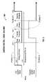
- FIG. 3is a switch control state machine 300 for the microwave energy delivery, measurement and control system of the present disclosure.
- the position of the hot switch relay 125is indicated in the upper timing diagram of FIG. 3 and the position of the transfer switch 140 is indicated in the lower timing diagram.
- a measurement period 310includes an energy delivery period 320 , a clear line period 330 , a first transfer transient period 340 , a precision network analyzer sweep period 350 and a second transfer transient period 360 .
- the energy delivery period 320is the period in which energy is delivered to the DUT 115 and initializes the start of a new measurement period 310 .
- the clear line period 330which follows the energy delivery period 320 , provides a delay in which the standing waves and transients in the system are allowed to dissipate through the circulator 135 and load 142 or the DUT 115 .
- the first transfer transient period 340provides a delay to allow the transfer switch 140 to transition from Position A to Position B.
- the precision network analyzer sweep period 350provides time for the precision network analyzer 150 to perform broadband scattering parameter measurements.
- the second transfer transient period 360provides a delay to allow the transfer switch 140 to transition from Position B to Position A.
- the time intervals of the timing diagrams in the switch control state machine 300 of FIG. 3are not necessarily to scale.
- the energy delivery period 320or the “on-time” in which microwave energy is delivered to the DUT 115 , is a majority of the measurement period 310 .
- the remaining portion of the measurement period 310or “off-time”, is split between the clear line period 330 , the first transfer transient period 340 , the precision network analyzer sweep period 350 and second transfer transient periods 360 .
- the clear line period 330 and the first and second transfer transient periods 340 , 360may be fixed in duration and based on the specific hardware used in the MRT system 100 .
- the precision network analyzer sweep period 350is based on one or more sampling parameters. Sampling parameters include the sweep bandwidth, the number of steps within the bandwidth, the number of samples taken at each step and the sampling rate.
- the clear line period 330must be sufficient in duration to allow all transients in the system to dissipate after the hot switch relay 125 switches from Position A to Position B.
- Transientsuch as, for example, standing waves or reflective energy, may “bounce” between components before eventually being dissipated or shunted by the reflected energy burn-off load resistor 142 , dissipated in the system 100 , or expended by the DUT 115 .
- the hot switch relay 125may switch from Position A to Position B in as little as about 360 Port ns, thereby leaving energy in the MRT 110 between the circulator 135 and the DUT 115 .
- the energymay be sufficiently high to damage the precision network analyzer 150 if energy is not dissipated.
- the amount of timeis related to the cable length, or path distance, between the antenna and the hot switch relay 125 .
- the signal speedis about 1.5 ns/ft for each direction.
- a circuit and cable length of about 10 feet between the DUT and the switch, a signal traveling away from the hot switch relay 125would travel once cycle, or the 20 feet between the hot switch relay 125 , the DUT 115 and back to the hot switch relay 125 , in about 30 ns.
- the signalmay ringing, or remain in the system, for as many as 5 cycles between the hot switch relay 125 and the DUT 115 , or about 150 ns.
- Circulatormay dissipate the standing waves to an acceptably low energy level in as little as one or two cycles between the DUT and the hot switch relay 125 .
- Transfer switch 140remains in Position A until the energy has dissipated to acceptably low energy levels.
- the clear line period 330is variable and determined by measurements performed by the precision network analyzer 150 or the CPU 120 . For example, measurements from the forward coupling port (Port 3 ) or the reverse coupling port (Port 4 ) of the directional coupler 145 may be used to determine if energy remains in the system.
- the hardware design, or at low microwave energy levels, the amount of transient energy remaining in the MRT 100 after the hot switch relay 125 transitions from Position A to Position B,may be minimal and may allow the clear line period 330 to be equal to, or about equal to, zero.
- First transfer transient periods 340provide a delay before initiating the precision network analysis sweep 350 .
- the first transfer transient period 340allows the transfer switch 140 to switch from Position A to Position B before the precision network analyzer 150 begins the broadband scattering parameter sweep.
- Second transfer transient period 360provides a delay before the subsequent measurement period begins (i.e., the next energy delivery period).
- the second transfer transient period 360allows the transfer switch 140 to switch from Position B to Position A before the hot switch relay 125 transitions from Position B to Position A and energy delivery to the DUT 115 resumes.
- the precision network analyzer 150determines broadband small-signal scattering parameter measurements.
- the sweep algorithm, and the amount of time to perform the sweep algorithm,is determined by the specific control algorithm executed by the CPU 120 .
- the measurements taken during the precision network analyzer sweep period 350are active measurements wherein the precision network analyzer 150 drives the DUT 115 with a broadband signal and measures at least one parameter related to the signal (i.e., S 11 , reflection coefficient, reflection loss).
- the CPU 120uses at least one of an active measurement taken by the network analyzer 350 during the broadband small signal scattering parameter measurements or a passive measurements from the directional coupler 145 in a feedback algorithms to control further energy delivery and/or subsequent MRT 100 operation.
- Energy delivery timemay be adjusted.
- the initial duration of the energy deliverymay be based on historical information or based on at least one parameter measured during the calibration or start-up states, 220 210 , discussed hereinabove.
- the “on-time”may be subsequently adjusted, either longer or shorter, in duration. Adjustments in the “on-time” may be based on the measurements performed by one of the precision network analyzer 150 and the CPU 120 , from historical information and/or patient data.
- the initial duration of an energy delivery period 320 in the ablation proceduremay be about 95% of the total measurement period 310 with the remaining percentage, or “off-time”, reserved for measurement (“on-time” duty cycle approximately equal to about 95%).
- the “on-time” duty cyclemay be reduced to between 95% and 5% to reduce the risk of producing tissue char and to provide more frequent measurements.
- the “off-time”may also be used to perform additional procedures that provide beneficial therapeutic effects, such as, for example, tissue hydration, or for purposes of tissue relaxation.
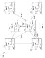
- the MRT 400includes a signal generator 405 , a microwave amplifier 410 , a directional coupler 445 , a transfer switch 440 , a terminator 455 , an attenuator 460 , a precision network analyzer 450 and a DUT 415 .
- the precision network analyzer 450performs active and passive measurements of various system parameters of the MRT 400 .
- MRT 400includes a signal generator 405 and amplifier 410 to generate and supply a high energy microwave signal to the directional coupler 445 .
- the directional coupler 445passes the signal to Port 2 of the transfer switch 440 and the transfer switch 440 passes the signal to the DUT 415 through Port 3 .
- the high energy microwave signalis passed to a terminator 455 connected to Port 1 of the transfer switch 440 .
- Precision network analyzer 450connects the first and second passive ports 451 , 452 to the forward and reflected power ports, Ports 3 and 4 , of the directional coupler 445 , respectively.
- the active port 453 of the precision network analyzer 450connects to Port 4 of the transfer switch 440 .
- Precision network analyzer 450may connect to Port 4 of the transfer switch 440 through a suitable attenuator 460 as illustrated in FIG. 4 and discussed hereinabove.
- the precision network analyzer 450 of the MRT 400passively measures forward and reflected power of the high energy microwave signal from the forward and reflected power ports, Ports 3 and 4 , respectively, of the directional coupler 445 .
- the precision network analyzer 450 of the MRT 400actively performs broadband scattering parameter measurements by connecting to the DUT 415 through Ports 3 and 4 of the transfer switch 440 .
- the precision network analyzer 450drives the DUT 415 with a signal at a range of frequencies and measures at least one parameter related to the DUT 415 at a plurality of frequencies.
- Transfer switch 440may be a single-pole, dual-throw coaxial switch that provides sufficient electrical isolation between Port 2 and Port 4 of the transfer switch 440 thereby preventing the high energy signal from damaging the precision network analyzer 450 in either the energy delivery mode, the measurement mode and while switching therebetween.
- Attenuator 460provides sufficient signal attenuation to prevent the high energy signal from damaging the precision network analyzer 450 .
- attenuator 460may be a limiting-type device as discussed hereinabove.
- the MRT 500includes a signal generator 505 , an amplifier 510 , a CPU 520 , a hot switch relay 525 , an amplifier burn-off load resistor 530 , a circulator 535 , a transfer switch 540 , an attenuator 560 , a precision network analyzer 550 and a tuner 565 positioned between the dual directional coupler 545 and the DUT 515 .
- the tuner 565may be a tuning network or tuning circuit configured to match the impedance of the delivery system with the impendence of the DUT 515 or, alternatively, the tuner 565 is configured to match the impedance of the DUT 515 to the impedance of the delivery system.
- Tuner 565may include a variable stub tuning network, a diode network or any other automated tuning network or circuit capable of high power operation and having the ability to match the DUT 565 impedance variations to the MRT 500 system impedance over the cooking cycle.
- the CPU 520characterizes the tuner 565 and removes the tuner 565 from the signal measured in the active measurement portion of the measuring cycle.
- Tuner 565may be incorporated into the DUT 515 wherein the CPU 520 directs the tuner 565 to actively changes one or more properties of the antenna (not shown) in the DUT 515 such that the antenna impedance appears to be about equal to a characteristic impedance, e.g. 50 Ohms.
- the CPU 520may instruct the tuner 565 to change the effective antenna length or change one or more dielectric properties.
- the CPU 520may use feedback from the measurement system to optimize energy delivery to the DUT 515 during at least a portion of the ablation procedure. Optimization may include: changing the frequency of the delivered microwave energy to better match the impedance of the DUT 515 , using the tuner 565 to adjust the output impedance of the MRT 500 to match the impendence of the DUT 515 or a combination thereof.
- the supervisory control systemuses a forward power measurement from directional coupler 545 , a reverse power measurement from the directional coupler 545 , or one or more broadband scattering perimeter measurements to optimize energy delivery.
- FIG. 6is a switch control state machine 600 for the microwave energy delivery, measurement and control system 500 illustrated in FIG. 5 .
- the position of the hot switch relay 525is indicated in the upper timing diagram and the position of the transfer switch 540 is indicated in the lower timing diagram.
- a measurement period 610includes an energy delivery period 620 , a clear line period 630 , a first transfer transient period 640 , a measurement, CPU processing and tuner control period 650 and a second transfer transient period 660 .
- the clear line period 630is after the energy delivery period 620 and provides a delay in which the standing waves and transients in the MRT 500 are allowed to dissipate.
- the first transfer transient period 640provides a delay to allow the transfer switch 540 to transition from Position A to Position B.
- the measurement, CPU processing and tuner control period 650allows the precision network to perform broadband scattering parameter measurements, perform control algorithms in the CPU and to perform adjustments to system tuning.
- the second transfer transient period 660provides a delay to allow the transfer switch 540 to transition from Position B to Position A.
- the time intervals of the timing diagrams in the switch control state machine 600 of FIG. 6are not to scale.
- the energy delivery period 620or “on-time” in which microwave energy is delivered to the DUT 515 , is typically equal to a majority of the measurement period 610 .
- the remaining portion of the measurement period, or “off-time”,is split between the clear line period 630 , the first transfer transient period 640 , the measurement, CPU processing and tuner control period 650 and second transfer transient periods 660 .
- the clear line period 630 and the first and second transfer transient periods 640 , 660may be fixed in duration and based on specific hardware in the system.
- the measurement, CPU processing and tuner control period 650is based on the sampling parameter, processing time or tuner control time.
- Sampling parametersinclude the sweep bandwidth, the number of steps within the bandwidth, the number of samples taken at each step and the sampling rate.
- the CPU processingincludes the execution of the tuner algorithm and the tuner control time includes a frequency adjustment, a tuner adjustment or any related system settling time.
- the clear line period 630must be sufficient in duration to allow all transients in the system to dissipate after the hot switch relay 625 switches from Position A to Position B.
- Transientsuch as, for example, standing waves or reflective energy, may “bounce” between components before eventually being dissipated or shunted through the reflected energy burn-off load resistor 642 , dissipated in the system, or expended by the DUT 615 .
- the hot switch relay 625may switch in from Position A to Position B in as little as about 360 ns, thereby leaving energy in the circuit between the circulator 635 and the DUT 615 .
- the transfer switch 540remains in Position A until the energy has dissipated to acceptably low energy levels.
- the amount of time for the energy to dissipateis dependent on the circuit and cable length in which the standing waves must travel.
- the clear line period 630is variable and determined by the precision network analyzer 550 or the CPU 520 measurements. For example, measurements from the forward coupling port (Port 3 ) and the reverse coupling port (Port 4 ) of the directional coupler 545 , may be used to determine if energy remains in the system.
- First transfer transient period 640provides a delay before initiating the measurement, CPU processing and tuner control period 650 .
- the first transfer transient period 640allows the transfer switch 540 to switch from Position A to Position B before the precision network 550 begins the broadband scattering parameter sweep.
- Second transfer transient period 360provides a delay before the subsequent measurement period begins (i.e., the next energy delivery period).
- the second transfer transient period 660allows the transfer switch 640 to switch from Position B to Position A before the hot switch relay 525 transitions from Position B to Position A and energy delivery to the DUT 515 resumes.
- the precision network analyzer 550determines broadband small-signal scattering parameter measurements.
- the measurement algorithmis determined by the specific control algorithm used by the supervisory control system and is similar to the precision network analyzer sweep algorithm discussed hereinabove.
- the supervisory control system, or CPU 520the active measurements of the broadband small signal scattering parameter measurements or the passive measurements from the directional coupler 545 in a tuning algorithm.
- the tuning algorithmchecks for the presence of a mismatch in impedance between the MRT 500 , the DUT 515 , and/or any combination thereof, and determines if an adjustment is necessary to correct the impedance mismatch.
- Energy delivery timemay be adjusted.
- the initial duration of the energy deliverymay be based on historical information or based on at least one parameter measured during the calibration or start-up states, 220 210 , discussed hereinabove.
- the “on-time”may be subsequently adjusted, either longer or shorter, in duration. Adjustments may be based on the measurements performed by the precision network analyzer 550 and/or the CPU 520 or from historical information and/or patient data.
- the initial duration of an energy delivery period in the ablation proceduremay be about 95% of the total measurement period with the remaining percentage, or “off-time”, reserved for measurement (“on-time” duty cycle approximately equal to about 95%).
- the “on-time” duty cyclemay be reduced to between 95% and 5% to reduce the risk of producing tissue char and to provide more frequent measurements.
- the “off-time”may also be used to perform additional procedures that provide beneficial therapeutic effects, such as, tissue hydration, or for purposes of tissue relaxation.
- tuning algorithmmay initiate a re-hydration of tissue to reduce tissue impedance instead of adjusting the frequency or re-tuning the MRT.
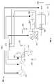
- MRT 700includes a variable attenuator 770 that replaces the hot switch relay 125 in the MRT 100 in FIG. 1 .
- the MRT 700includes a signal generator 705 , a variable attenuator 770 , an amplifier 710 , a CPU 720 , a circulator 735 , a load resistor 742 , a transfer switch 740 , a transfer switch load resistor 755 , an attenuator 760 , a precision network analyzer 750 , and a directional coupler 745 that connects to the DUT.
- the signal generator 705supplies a microwave frequency signal to the variable attenuator 770 .
- Variable attenuator 770includes a variable network or circuit that scales the signal from the signal generator 705 between 0% and 100% and provides the scaled signal to the amplifier 710 .
- Amplifier 710amplifies the signal by a fixed amount and provides the signal to the circulator 735 .
- the MRT 100 in FIG. 1controls the energy output (i.e., the power of the microwave signal) by adjusting the output of the signal generator 105 and/or the gain of the amplifier 110 (i.e., signal from the signal generator 105 amplified by the gain of the amplifier 710 ).
- the energy outputis controlled by one or more of the signal generator 705 , the variable attenuator 770 and the amplifier 710 .
- the output energy of the MRT 700 in FIG. 7is equal to the signal generator 705 output scaled by variable attenuator 770 attenuation percentage and amplified by the gain of the amplifier 710 .
- Position A of the hot switch relay 125is equivalent to the variable attenuator 770 is Position A (i.e., a scaling factor of 100%).
- Position Aprovides microwave energy to Port A of the circulator 135 and 735 , respectively.
- Position B of the hot switch relay 125is equivalent to the variable attenuator 770 in Position B (i.e., a scaling factor of 0%).
- Position B in both FIGS. 1 and 7no microwave energy signal is provided to Port A of the circulator 135 and 735 , respectively.
- the hot switch relay 125 in the MRT 100 of FIG. 1includes a switch that switches between Position A and Position B and is capable of executing the transition in a minimum amount of time to prevent transients or spikes in the waveform.
- the variable attenuator 770 in the MRT 700 of FIG. 7may includes an automated variable attenuator, such as, for example, a rheostat-like circuit that does not switch but transitions between Position A and Position B thereby generating fewer transients compared to the switch in FIG. 1 .
- Attenuator activation timewould be added to the dissipation time calculation for safe switching and measurement.
- the DUTincludes a MRT calibration device configured to measure the length of the transmission path from the antenna feedpoint to the directional coupler and each respective signal to the network analyzer.
- FIG. 8is a schematic representation of an ablation device for use in calibrating a microwave energy delivery, measurement and control system of the present disclosure.
- a microwave energy delivery systemmay be preformed by various calibration procedures. For example, one of a Short-Open-Load (SOL), a Short-Open-Load-Thru (SOLT), a Short-Short-Load-Thru (SSLT) and a Thru-Reflect-Line (TRL) calibration technique may be used.
- SOLShort-Open-Load
- SOLTShort-Open-Load-Thru
- SSLTShort-Short-Load-Thru
- TRLThru-Reflect-Line
- the systemis calibrated with a Short-Open (SO) calibration technique.
- SOShort-Open
- the SO calibrationprovides a determination of the relative performance of the DUT.
- the Short-Open calibration techniqueis known in the art and is generally described hereinbelow.
- the first step of the SO calibrationis preformed by running the microwave generator with a “short” at the output of the microwave generator (i.e., the coaxial cable connector).
- the second step of the SO calibrationis preformed by running the microwave generator with the output of the microwave generator “open”.
- the two steps of the SO calibrationwhich is often referred to as “shifting a reference plane” allows the generator to analyze the system up to the output of the directional coupler.
- shifting a reference planeallows the generator to analyze the system up to the output of the directional coupler.
- FIG. 8Aillustrates the directional coupler 845 at the output of a microwave generator 810 and a coaxial cable 820 that connects the microwave generator 810 to an MRT calibration device 800 of the present disclosure.
- the MRT calibration device 800includes a transmission portion 830 and an antenna portion 840 .
- FIG. 8Billustrates the transition between the transmission portion 830 and the antenna portion 840 .
- Switching mechanism 850is located adjacent on the proximal portion of the antenna under test 840 and on the distal portion of the transmission portion 830 of the MRT calibration device 800 . Switching mechanism 850 allows the system to perform an SO calibration without replacing the DUT.
- Switching mechanism 850is further illustrated in FIG. 8C and includes an open circuit switch 850 a , a short circuit switch 850 b and a short circuit load 840 a.
- the switching mechanism 850 in the MRT calibration device 800allows the reference plane to be shifted to a point proximal the antenna thereby accounting for a majority of the transmission path in the calibration procedure.
- An open circuitis first obtained by the open circuit control 836 actuating the open circuit switch 850 a to an open position thereby disconnecting the inner conductor 832 and outer conductor 834 from the antenna under test 815 .
- a short circuit between the inner conductor 832 and the outer conductor 834 through a short circuit load 840 ais obtained by the short-circuit control 838 transitioning the short circuit switch 850 b from Position A to Position B.
- the short circuit load 840 ais a fixed load that replaces the antenna under test 815 .
- the short circuit load 840 ais an antenna with a feedpoint equivalent to the antenna under test 815 thereby providing a known antenna response that can be used to calibrate the antenna under test 815 .
- the systemyields a known phase and amplitude of the reflected energy at the antenna feed.
- the antenna under test 840is replaced with a short circuit load 840 b that may include an equivalent path-length and/or an equivalent antenna.
- Energy provided to the short circuit load 840 ais reflected at the short circuit load 840 a with a specific phase for the returned signal.
- the short circuit load 840 areturns energy at a first phase and the open returns energy at a second phase.
- the short circuit load 840 aplaces a voltage minimum at the short and full standing waves at every ⁇ /4 and 3 ⁇ /4 wavelengths on the transmission line proximal the short circuit load 840 a .
- the open circuit 850 aplaces full standing waves at the open and every ⁇ /2 wavelengths on the transmission line proximal the open circuit 850 a.
- phase angle and returned power of the antennamay be determined.
- An active tuning circuitmay use one or more of these parameters to determine one or more system tuning parameters.
- an active tuning circuitmay be placed in the generator, the handle of the microwave energy delivery device or any other suitable location. Active tuning circuit may determine a range of mismatch and/or provide one or more calibration parameters to the system or may properly calibrate to the antenna feedpoint.
- the antenna and/or the tissuemay be behaving inductively (i.e., 50 ⁇ +20 ⁇ j wherein the positive 20 ⁇ j is inductive) or capacitively (i.e., 50 ⁇ 20 ⁇ j wherein the negative 20 ⁇ j is inductive).
- the systemcan identify if the antenna and/or tissue is behaving inductively or capacitively.
- the systemcan incorporate a matching network to offset the impedance mismatch.
- calibrationis performed by placing the antenna 940 of a microwave energy delivery device 915 in a calibration apparatus 900 .
- Calibration apparatus 900includes a chamber 910 a configured to produce a known reflection and phase shift in an antenna 940 a when the antenna 940 a is placed adjacent the chamber 910 a .
- Calibrationis performed by placing the antenna 940 a in a fixed position relative to the chamber 910 a and driving the antenna 940 a with a predetermined signal.
- the microwave generator 905 aconnects to microwave energy delivery device 920 a via a cable 920 a and measures one or more parameters indicative of the performance of the antenna 940 a and compares the measured parameters with one or more predetermined parameters.
- the microwave generator 905 adetermines one or more calibration parameters or one or more tuning parameters for the antenna 940 a under test.
- Chamber 910 amay be a cylindrical shaped chamber configured to receive the antenna 940 a .
- Chamber 910 amay receive the distal end of the microwave energy delivery device 915 a , including the antenna 940 a , as illustrated in FIG. 9A , or chamber 940 b may be configured to receive the microwave energy delivery device 915 b , as illustrated in FIG. 9B .
- a positioning mechanism or stop mechanismmay provide consistent placement of the antenna in the chamber. Stopping mechanism may include a sensing mechanism to sense the placement in the chamber. Sensing mechanism may provide a signal to the system to indicate that the antenna is in position. System, after receiving the signal from the sensing mechanism, may be configured to switch to a test mode in which the system drives the antenna with a predetermined microwave signal.
- Calibration device 940 amay be configured as a stand-alone device as illustrated in FIG. 9A , configured to interface with the microwave energy delivery device (not shown), configured to interface with the microwave generator, as illustrated in FIG. 9B or any combination thereof.
- Calibration device 900 amay be a passive device that provides a load on the antenna 940 a wherein the antenna response 940 a to the load 900 a (the calibration device) is known to the microwave generator 905 a.
- calibration device 900 a , 900 bmay include a chamber 910 a , 910 b configured to receive at least a portion of the microwave energy delivery device 915 a , 915 b .
- Chamber 910 a , 910 bmay be configured to receive the antenna 940 a , 940 b or the antenna and a portion of the device transmission line 930 a , 930 b .
- Chamber 910 a , 910 bis configured to position a microwave energy absorbing load relative to the antenna 940 a , 940 b.
- a clinicianmates together the calibration device 900 a , 900 b and the microwave energy delivery device 915 a , 915 b , respectively.
- the antenna 940 a , 940 b of the microwave energy delivery device 915 a , 915 bis positioned relative to calibration device 900 a , 900 b , respectively, and a calibration procedure is performed.
- the calibration proceduremay be initiated manually, by the clinician, via a microwave generator input 906 a , 906 b or interface screen 907 a , 907 b or by an input on the microwave energy delivery device (not shown).
- the calibration proceduremay be automatically initiated by the microwave generator 905 b .
- placement of the antenna 940 b relative to the load in the calibration device 900 bmay trigger a sensor 901 b or input to the microwave generator 905 b (not shown) and a calibration procedure may be automatically initiated.
- the calibration procedureincludes the steps of driving the antenna with a microwave energy signal, measuring at least one parameter related to the antenna and generating at least one antenna calibration parameter.
- the microwave energy signalmay be a predetermined signal, a signal selected by the clinician or a signal selected for the specific antenna.
- the one or more parameters related to the antennamay include one of forward power, reflected power, impedance and temperature.
- the at least one antenna calibration parameteris related to the operation of the antenna, such as, for example, a parameter related to antenna tuning, a parameter related to the resonance of the antenna, a parameter related to antenna construction or any other suitable parameter related to microwave energy delivery.
- Calibration devicemay be configured to interface with one of the microwave energy delivery device or the microwave generator. As illustrated in FIG. 9B , calibration device 900 b may connect to the microwave generator 905 b via a cable 820 b . In another embodiment, the calibration device 900 b may include a connector (not shown) that interfaces with the microwave energy delivery device 915 b when mated together. Connection between the calibration device 900 b and microwave generator 905 b or microwave energy delivery device 915 b may also be configured as a wireless connection. Connection may include one or more digital or analog connections or may include a suitable communication means, such as, for example, TCP/IP, OSI, FTP, UPnP, iSCSI, IEEE 802.15.1 (Bluetooth) or Wireless USB. Calibration device 900 b may provide one or more parameters related to the calibration device 900 b and/or the calibration procedure to one of the microwave energy delivery device 915 b and the microwave generator 905 b.
- Calibration devicemay be configured to interface with one of the microwave energy delivery device or the microwave generator. As illustrated in FIG. 9B , calibration device 900 b may connect to the microwave generator 905 b via a cable 920 b . In another embodiment, the calibration device 900 b may include a connector (not shown) that interfaces with the microwave energy delivery device 915 b when mated together. Connection between the calibration device 900 b and microwave generator 905 b or microwave energy delivery device 915 b may also be configured as a wireless connection. Connection may include one or more digital or analog connections or may include a suitable communication means, such as, for example, TCP/IP, OSI, FTP, UPnP, iSCSI, IEEE 802.15.1 (Bluetooth) or Wireless USB. Calibration device 900 b may provide one or more parameters related to the calibration device 900 b and/or the calibration procedure to one of the microwave energy delivery device 915 b and the microwave generator 905 b.
- Calibration device 900 bmay further include a locking mechanism 903 , 904 , 909 for locking the calibration device 900 b to the microwave energy delivery device 915 b .
- catches 904align with slots 909 when chamber 910 b is in a closed position.
- Slide 903actuates catches 904 within the slots thereby locking the chamber in a closed position.
- Any suitable locking mechanismmay be used such as, for example, a clip, a latch, a pressed fit pin, a locking or self-closing hinge, a magnetic or electronic closure mechanism or any other suitable locking mechanism.
- Slide 903 or other locking release mechanismmay be configured to be disabled when the antenna 940 b is activated thereby preventing the calibration device 900 b from releasing the microwave energy delivery device 915 b during calibration or energy delivery.
Landscapes
- Health & Medical Sciences (AREA)
- Surgery (AREA)
- Life Sciences & Earth Sciences (AREA)
- Biomedical Technology (AREA)
- Medical Informatics (AREA)
- Nuclear Medicine, Radiotherapy & Molecular Imaging (AREA)
- Electromagnetism (AREA)
- Engineering & Computer Science (AREA)
- Physics & Mathematics (AREA)
- Heart & Thoracic Surgery (AREA)
- Otolaryngology (AREA)
- Molecular Biology (AREA)
- Animal Behavior & Ethology (AREA)
- General Health & Medical Sciences (AREA)
- Public Health (AREA)
- Veterinary Medicine (AREA)
- Surgical Instruments (AREA)
- Constitution Of High-Frequency Heating (AREA)
- Discharge-Lamp Control Circuits And Pulse- Feed Circuits (AREA)
Abstract
Description
dissipation time=(2×distance*1.5 ns/ft)*safety factor;
wherein the distance equals the circuit length plus the cable length, safety factor equals 2 or 3 and the speed of 1.5 ns/ft is based upon approximately ∈r=2 for typical transmission line cables
Claims (9)
Priority Applications (6)
| Application Number | Priority Date | Filing Date | Title |
|---|---|---|---|
| US12/242,026US8248075B2 (en) | 2008-09-30 | 2008-09-30 | System, apparatus and method for dissipating standing wave in a microwave delivery system |
| JP2009225622AJP5188482B2 (en) | 2008-09-30 | 2009-09-29 | System, apparatus and method for dissipating standing waves in a microwave delivery system |
| CA2680937ACA2680937A1 (en) | 2008-09-30 | 2009-09-29 | System, apparatus and method for dissipating standing wave in a microwave delivery system |
| EP09012400AEP2168524B1 (en) | 2008-09-30 | 2009-09-30 | System for dissipating standing wave in a microwave delivery system |
| AU2009222511AAU2009222511B2 (en) | 2008-09-30 | 2009-09-30 | System, apparatus and method for dissipating standing wave in a microwave delivery system |
| AT09012400TATE551012T1 (en) | 2008-09-30 | 2009-09-30 | SYSTEM FOR DISCHARGING STATIONARY WAVES IN A MICROWAVE DELIVERY SYSTEM |
Applications Claiming Priority (1)
| Application Number | Priority Date | Filing Date | Title |
|---|---|---|---|
| US12/242,026US8248075B2 (en) | 2008-09-30 | 2008-09-30 | System, apparatus and method for dissipating standing wave in a microwave delivery system |
Publications (2)
| Publication Number | Publication Date |
|---|---|
| US20100079215A1 US20100079215A1 (en) | 2010-04-01 |
| US8248075B2true US8248075B2 (en) | 2012-08-21 |
Family
ID=41531667
Family Applications (1)
| Application Number | Title | Priority Date | Filing Date |
|---|---|---|---|
| US12/242,026Expired - Fee RelatedUS8248075B2 (en) | 2008-09-30 | 2008-09-30 | System, apparatus and method for dissipating standing wave in a microwave delivery system |
Country Status (6)
| Country | Link |
|---|---|
| US (1) | US8248075B2 (en) |
| EP (1) | EP2168524B1 (en) |
| JP (1) | JP5188482B2 (en) |
| AT (1) | ATE551012T1 (en) |
| AU (1) | AU2009222511B2 (en) |
| CA (1) | CA2680937A1 (en) |
Cited By (27)
| Publication number | Priority date | Publication date | Assignee | Title |
|---|---|---|---|---|
| US20110028963A1 (en)* | 2009-08-03 | 2011-02-03 | Tyco Healthcare Group Lp | Power Level Transitioning in a Surgical Instrument |
| US20110131477A1 (en)* | 2009-12-01 | 2011-06-02 | Stanley Jungleib | Systems and Methods for Analyzing and Affecting Subtle Energy |
| US20120092903A1 (en)* | 2010-10-19 | 2012-04-19 | Power Integrations, Inc. | Power transfer between independent power ports utilizing a single transformer |
| US8486061B2 (en) | 2009-01-12 | 2013-07-16 | Covidien Lp | Imaginary impedance process monitoring and intelligent shut-off |
| US8608733B2 (en) | 2008-03-28 | 2013-12-17 | Covidien Lp | Electrosurgical apparatus with predictive RF source control |
| US8760226B2 (en) | 2009-11-16 | 2014-06-24 | Covidien Lp | Class resonant-H electrosurgical generators |
| US8968295B2 (en) | 2008-09-05 | 2015-03-03 | Covidien Lp | Electrosurgical apparatus with high speed energy recovery |
| US20150219719A1 (en)* | 2012-10-10 | 2015-08-06 | Zumtobel Lighting Gmbh | System for monitoring the operation of a current loop |
| US9119624B2 (en) | 2006-04-24 | 2015-09-01 | Covidien Ag | ARC based adaptive control system for an electrosurgical unit |
| US9186201B2 (en) | 2008-09-05 | 2015-11-17 | Covidien Lp | Electrosurgical apparatus with high speed energy recovery |
| US9254172B2 (en) | 2008-09-03 | 2016-02-09 | Covidien Lp | Shielding for an isolation apparatus used in a microwave generator |
| US9522039B2 (en) | 2009-03-11 | 2016-12-20 | Covidien Lp | Crest factor enhancement in electrosurgical generators |
| US9522038B2 (en) | 2008-03-13 | 2016-12-20 | Covidien Lp | Crest factor enhancement in electrosurgical generators |
| US9636165B2 (en) | 2013-07-29 | 2017-05-02 | Covidien Lp | Systems and methods for measuring tissue impedance through an electrosurgical cable |
| US9757196B2 (en) | 2011-09-28 | 2017-09-12 | Angiodynamics, Inc. | Multiple treatment zone ablation probe |
| US9872719B2 (en) | 2013-07-24 | 2018-01-23 | Covidien Lp | Systems and methods for generating electrosurgical energy using a multistage power converter |
| US9895189B2 (en) | 2009-06-19 | 2018-02-20 | Angiodynamics, Inc. | Methods of sterilization and treating infection using irreversible electroporation |
| US9901386B2 (en) | 2014-01-13 | 2018-02-27 | Covidien Lp | Systems and methods for multifrequency cable compensation |
| US10039588B2 (en) | 2009-12-16 | 2018-08-07 | Covidien Lp | System and method for tissue sealing |
| US10942231B2 (en) | 2016-08-30 | 2021-03-09 | Koninklijke Philips N.V. | Transmit/receive radio frequency (RF) system for a magnetic resonance examination system and method thereof |
| US11707629B2 (en) | 2009-05-28 | 2023-07-25 | Angiodynamics, Inc. | System and method for synchronizing energy delivery to the cardiac rhythm |
| US11723710B2 (en) | 2016-11-17 | 2023-08-15 | Angiodynamics, Inc. | Techniques for irreversible electroporation using a single-pole tine-style internal device communicating with an external surface electrode |
| US11931096B2 (en) | 2010-10-13 | 2024-03-19 | Angiodynamics, Inc. | System and method for electrically ablating tissue of a patient |
| US12102376B2 (en) | 2012-02-08 | 2024-10-01 | Angiodynamics, Inc. | System and method for increasing a target zone for electrical ablation |
| US12114911B2 (en) | 2014-08-28 | 2024-10-15 | Angiodynamics, Inc. | System and method for ablating a tissue site by electroporation with real-time pulse monitoring |
| US12201349B2 (en) | 2009-04-03 | 2025-01-21 | Angiodynamics, Inc. | Congestive obstruction pulmonary disease (COPD) |
| US12226143B2 (en) | 2020-06-22 | 2025-02-18 | Covidien Lp | Universal surgical footswitch toggling |
Families Citing this family (28)
| Publication number | Priority date | Publication date | Assignee | Title |
|---|---|---|---|---|
| US7137980B2 (en) | 1998-10-23 | 2006-11-21 | Sherwood Services Ag | Method and system for controlling output of RF medical generator |
| US7044948B2 (en) | 2002-12-10 | 2006-05-16 | Sherwood Services Ag | Circuit for controlling arc energy from an electrosurgical generator |
| AU2004235739B2 (en) | 2003-05-01 | 2010-06-17 | Covidien Ag | Method and system for programming and controlling an electrosurgical generator system |
| WO2005050151A1 (en) | 2003-10-23 | 2005-06-02 | Sherwood Services Ag | Thermocouple measurement circuit |
| US7396336B2 (en) | 2003-10-30 | 2008-07-08 | Sherwood Services Ag | Switched resonant ultrasonic power amplifier system |
| US7947039B2 (en) | 2005-12-12 | 2011-05-24 | Covidien Ag | Laparoscopic apparatus for performing electrosurgical procedures |
| CA2574934C (en) | 2006-01-24 | 2015-12-29 | Sherwood Services Ag | System and method for closed loop monitoring of monopolar electrosurgical apparatus |
| US7794457B2 (en) | 2006-09-28 | 2010-09-14 | Covidien Ag | Transformer for RF voltage sensing |
| US8377054B2 (en)* | 2009-09-24 | 2013-02-19 | Covidien Lp | Automatic control circuit for use in an electrosurgical generator |
| US8685015B2 (en)* | 2009-09-24 | 2014-04-01 | Covidien Lp | System and method for multi-pole phase-shifted radio frequency application |
| GB2474233A (en) | 2009-10-06 | 2011-04-13 | Uk Investments Associates Llc | Cooling pump comprising a detachable head portion |
| PL2445312T3 (en) | 2010-10-22 | 2017-06-30 | Whirlpool Corporation | Microwave heating apparatus and method of operating such a microwave heating apparatus |
| US9028482B2 (en) | 2011-07-19 | 2015-05-12 | Covidien Lp | Microwave and RF ablation system and related method for dynamic impedance matching |
| US9192422B2 (en) | 2011-07-19 | 2015-11-24 | Covidien Lp | System and method of matching impedances of an electrosurgical generator and/or a microwave generator |
| US8968297B2 (en) | 2011-07-19 | 2015-03-03 | Covidien Lp | Microwave and RF ablation system and related method for dynamic impedance matching |
| US9033973B2 (en) | 2011-08-30 | 2015-05-19 | Covidien Lp | System and method for DC tissue impedance sensing |
| US9039693B2 (en) | 2011-09-20 | 2015-05-26 | Covidien Lp | Handheld medical devices including microwave amplifier unit at device handle |
| US9039692B2 (en) | 2011-09-20 | 2015-05-26 | Covidien Lp | Handheld medical devices including microwave amplifier unit at device handle |
| US8745846B2 (en) | 2011-09-20 | 2014-06-10 | Covidien Lp | Method of manufacturing handheld medical devices including microwave amplifier unit |
| US9023025B2 (en) | 2011-09-20 | 2015-05-05 | Covidien Lp | Handheld medical devices including microwave amplifier unit at device handle |
| US9033970B2 (en) | 2011-09-20 | 2015-05-19 | Covidien Lp | Handheld medical devices including microwave amplifier unit at device handle |
| US8968290B2 (en) | 2012-03-14 | 2015-03-03 | Covidien Lp | Microwave ablation generator control system |
| WO2016070009A1 (en) | 2014-10-31 | 2016-05-06 | Medtronic Advanced Energy Llc | Power monitoring circuitry and method for reducing leakage current in rf generators |
| US10376309B2 (en) | 2016-08-02 | 2019-08-13 | Covidien Lp | Ablation cable assemblies and a method of manufacturing the same |
| US11065053B2 (en) | 2016-08-02 | 2021-07-20 | Covidien Lp | Ablation cable assemblies and a method of manufacturing the same |
| US11197715B2 (en) | 2016-08-02 | 2021-12-14 | Covidien Lp | Ablation cable assemblies and a method of manufacturing the same |
| CN114870267B (en)* | 2022-06-24 | 2024-01-30 | 北京中成康富科技股份有限公司 | Millimeter wave therapeutic apparatus for oral cavity |
| USD1084316S1 (en) | 2023-11-20 | 2025-07-15 | Angiodynamics, Inc. | Ferrule |
Citations (112)
| Publication number | Priority date | Publication date | Assignee | Title |
|---|---|---|---|---|
| DE179607C (en) | 1906-11-12 | |||
| DE390937C (en) | 1922-10-13 | 1924-03-03 | Adolf Erb | Device for internal heating of furnace furnaces for hardening, tempering, annealing, quenching and melting |
| GB607850A (en) | 1946-04-01 | 1948-09-06 | William George Curwain | Electric connectors |
| GB702510A (en) | 1951-03-24 | 1954-01-20 | Foxboro Co | Improvements in temperature responsive instruments |
| GB855459A (en) | 1958-04-11 | 1960-11-30 | Keeler Optical Products Ltd | Improvements in or relating to electro-surgical apparatus |
| DE1099658B (en) | 1959-04-29 | 1961-02-16 | Siemens Reiniger Werke Ag | Automatic switch-on device for high-frequency surgical devices |
| FR1275415A (en) | 1960-09-26 | 1961-11-10 | Device for detecting disturbances for electrical installations, in particular electrosurgery | |
| GB902775A (en) | 1959-05-16 | 1962-08-09 | Kathleen Zilla Rumble | Improvements in or relating to electrical plugs |
| DE1139927B (en) | 1961-01-03 | 1962-11-22 | Friedrich Laber | High-frequency surgical device |
| DE1149832B (en) | 1961-02-25 | 1963-06-06 | Siemens Reiniger Werke Ag | High frequency surgical apparatus |
| FR1347865A (en) | 1962-11-22 | 1964-01-04 | Improvements to diathermo-coagulation devices | |
| DE1439302A1 (en) | 1963-10-26 | 1969-01-23 | Siemens Ag | High-frequency surgical device |
| DE2439587A1 (en) | 1973-08-23 | 1975-02-27 | Matburn Holdings Ltd | ELECTROSURGICAL DEVICE |
| DE2455174A1 (en) | 1973-11-21 | 1975-05-22 | Termiflex Corp | INPUT / OUTPUT DEVICE FOR DATA EXCHANGE WITH DATA PROCESSING DEVICES |
| DE2407559A1 (en) | 1974-02-16 | 1975-08-28 | Dornier System Gmbh | Tissue heat treatment probe - has water cooling system which ensures heat development only in treated tissues |
| DE2602517A1 (en) | 1975-01-23 | 1976-07-29 | Dentsply Int Inc | ELECTROSURGICAL DEVICE |
| DE2504280A1 (en) | 1975-02-01 | 1976-08-05 | Hans Heinrich Prof Dr Meinke | DEVICE FOR ELECTRIC TISSUE CUTTING IN SURGERY |
| US3998538A (en) | 1975-02-24 | 1976-12-21 | Xerox Corporation | Electrometer apparatus for reproduction machines |
| FR2313708A1 (en) | 1975-06-02 | 1976-12-31 | Sybron Corp | Electro surgical instrument impulse control circuit - has potentiometer between patient electrodes and threshold switch for excessive voltage |
| DE2540968A1 (en) | 1975-09-13 | 1977-03-17 | Erbe Elektromedizin | Circuit for bipolar coagulation tweezers - permits preparation of tissues prior to coagulation |
| FR2364461A1 (en) | 1976-09-09 | 1978-04-07 | Valleylab Inc | ELECTROSURGICAL EQUIPMENT SAFETY CIRCUIT AND ITS PROCESS FOR USE |
| DE2820908A1 (en) | 1977-05-16 | 1978-11-23 | Joseph Skovajsa | DEVICE FOR THE LOCAL TREATMENT OF A PATIENT IN PARTICULAR FOR ACUPUNCTURE OR AURICULAR THERAPY |
| DE2803275A1 (en) | 1978-01-26 | 1979-08-02 | Aesculap Werke Ag | HF surgical appts. with active treatment and patient electrodes - has sensor switching generator to small voltage when hand-operated switch is closed |
| DE2823291A1 (en) | 1978-05-27 | 1979-11-29 | Rainer Ing Grad Koch | Coagulation instrument automatic HF switching circuit - has first lead to potentiometer and second to transistor base |
| SU727201A2 (en) | 1977-11-02 | 1980-04-15 | Киевский Научно-Исследовательский Институт Нейрохирургии | Electric surgical apparatus |
| US4204549A (en) | 1977-12-12 | 1980-05-27 | Rca Corporation | Coaxial applicator for microwave hyperthermia |
| US4228809A (en)* | 1977-10-06 | 1980-10-21 | Rca Corporation | Temperature controller for a microwave heating system |
| US4247815A (en) | 1979-05-22 | 1981-01-27 | The United States Of America As Represented By The Secretary Of The Army | Method and apparatus for physiologic facsimile imaging of biologic targets based on complex permittivity measurements using remote microwave interrogation |
| DE2946728A1 (en) | 1979-11-20 | 1981-05-27 | Erbe Elektromedizin GmbH & Co KG, 7400 Tübingen | HF surgical appts. for use with endoscope - provides cutting or coagulation current at preset intervals and of selected duration |
| US4311154A (en) | 1979-03-23 | 1982-01-19 | Rca Corporation | Nonsymmetrical bulb applicator for hyperthermic treatment of the body |
| DE3143421A1 (en) | 1980-11-04 | 1982-05-27 | The Agency of Industrial Science and Technology, Tokyo | Laser scalpel |
| DE3045996A1 (en) | 1980-12-05 | 1982-07-08 | Medic Eschmann Handelsgesellschaft für medizinische Instrumente mbH, 2000 Hamburg | Electro-surgical scalpel instrument - has power supply remotely controlled by surgeon |
| FR2502935A1 (en) | 1981-03-31 | 1982-10-08 | Dolley Roger | Diathermic knife for coagulating tissues - has monitoring current added to HF coagulating current in order to control end of operation as function or resistance of coagulating tissues |
| DE3120102A1 (en) | 1981-05-20 | 1982-12-09 | F.L. Fischer GmbH & Co, 7800 Freiburg | ARRANGEMENT FOR HIGH-FREQUENCY COAGULATION OF EGG WHITE FOR SURGICAL PURPOSES |
| FR2517953A1 (en) | 1981-12-10 | 1983-06-17 | Alvar Electronic | Diaphanometer for optical examination of breast tissue structure - measures tissue transparency using two plates and optical fibre bundle cooperating with photoelectric cells |
| DE3510586A1 (en) | 1985-03-23 | 1986-10-02 | Erbe Elektromedizin GmbH, 7400 Tübingen | Control device for a high-frequency surgical instrument |
| FR2573301B3 (en) | 1984-11-16 | 1987-04-30 | Lamidey Gilles | SURGICAL PLIERS AND ITS CONTROL AND CONTROL APPARATUS |
| DE3604823A1 (en) | 1986-02-15 | 1987-08-27 | Flachenecker Gerhard | HIGH FREQUENCY GENERATOR WITH AUTOMATIC PERFORMANCE CONTROL FOR HIGH FREQUENCY SURGERY |
| EP0246350A1 (en) | 1986-05-23 | 1987-11-25 | Erbe Elektromedizin GmbH. | Coagulation electrode |
| US4741348A (en) | 1984-07-31 | 1988-05-03 | Tokyo Keiki Co., Ltd. | Heating apparatus for hyperthermia |
| US4744372A (en) | 1984-07-31 | 1988-05-17 | Tokyo Keiki Co., Ltd. | Heating apparatus and method for hyperthermia |
| GB2164473B (en) | 1984-09-10 | 1988-06-29 | Bard Inc C R | Electrosurgical generator |
| EP0296777A2 (en) | 1987-06-26 | 1988-12-28 | Microwave Medical Systems, Inc. | In-line microwave warming apparatus |
| EP0310431A2 (en) | 1987-09-30 | 1989-04-05 | Valleylab, Inc. | Apparatus for providing enhanced tissue fragmentation and/or hemostasis |
| EP0325456A2 (en) | 1988-01-20 | 1989-07-26 | G2 Design Limited | Diathermy unit |
| EP0336742A2 (en) | 1988-04-08 | 1989-10-11 | Bristol-Myers Company | Method and apparatus for the calibration of electrosurgical apparatus |
| DE3904558A1 (en) | 1989-02-15 | 1990-08-23 | Flachenecker Gerhard | Radio-frequency generator with automatic power control for radio-frequency surgery |
| EP0390937A1 (en) | 1989-04-01 | 1990-10-10 | Erbe Elektromedizin GmbH | Device for the surveillance of the adherence of neutral electrodes in high-frequency surgery |
| DE3942998A1 (en) | 1989-12-27 | 1991-07-04 | Delma Elektro Med App | Electro-surgical HF instrument for contact coagulation - has monitoring circuit evaluating HF voltage at electrodes and delivering switch=off signal |
| US5097846A (en) | 1986-12-15 | 1992-03-24 | Larsen Lawrence E | Apparatus for diathermy treatment and control |
| GB2214430B (en) | 1988-01-20 | 1992-06-17 | Nigel Mark Goble | Diathermy unit |
| EP0556705A1 (en) | 1992-02-20 | 1993-08-25 | DELMA ELEKTRO-UND MEDIZINISCHE APPARATEBAU GESELLSCHAFT mbH | High frequency surgery device |
| EP0608609A2 (en) | 1992-12-01 | 1994-08-03 | Cardiac Pathways Corporation | Catheter for RF ablation with cooled electrode and method |
| US5354325A (en)* | 1991-07-26 | 1994-10-11 | Institut National De La Sante Et De La Recherche Medicale | System for internal heat treatment of a specific body and its use |
| US5364392A (en) | 1993-05-14 | 1994-11-15 | Fidus Medical Technology Corporation | Microwave ablation catheter system with impedance matching tuner and method |
| US5405346A (en) | 1993-05-14 | 1995-04-11 | Fidus Medical Technology Corporation | Tunable microwave ablation catheter |
| DE4339049A1 (en) | 1993-11-16 | 1995-05-18 | Erbe Elektromedizin | Surgical system and instruments configuration device |
| US5562720A (en) | 1992-05-01 | 1996-10-08 | Vesta Medical, Inc. | Bipolar/monopolar endometrial ablation device and method |
| US5651780A (en) | 1991-11-08 | 1997-07-29 | Ep Technologies, Inc. | Systems for identifying catheters and monitoring their use |
| US5683382A (en) | 1995-05-15 | 1997-11-04 | Arrow International Investment Corp. | Microwave antenna catheter |
| EP0836868A2 (en) | 1996-10-18 | 1998-04-22 | Gebr. Berchtold GmbH & Co. | High frequency surgical apparatus and method for operating same |
| DE19717411A1 (en) | 1997-04-25 | 1998-11-05 | Aesculap Ag & Co Kg | Monitoring of thermal loading of patient tissue in contact region of neutral electrode of HF treatment unit |
| EP0880220A2 (en) | 1997-05-19 | 1998-11-25 | TRW Inc. | A phase staggered full-bridge converter with soft-PWM switching |
| US5865788A (en) | 1992-08-12 | 1999-02-02 | Vidamed, Inc. | Self-contained power sypply and monitoring station for RF tissue ablation |
| US5904709A (en) | 1996-04-17 | 1999-05-18 | The United States Of America As Represented By The Administrator Of The National Aeronautics And Space Administration | Microwave treatment for cardiac arrhythmias |
| US5931836A (en) | 1996-07-29 | 1999-08-03 | Olympus Optical Co., Ltd. | Electrosurgery apparatus and medical apparatus combined with the same |
| US5957969A (en) | 1993-05-14 | 1999-09-28 | Fidus Medical Technology Corporation | Tunable microwave ablation catheter system and method |
| US5961871A (en) | 1991-11-14 | 1999-10-05 | Lockheed Martin Energy Research Corporation | Variable frequency microwave heating apparatus |
| US5983141A (en) | 1996-06-27 | 1999-11-09 | Radionics, Inc. | Method and apparatus for altering neural tissue function |
| US6016452A (en) | 1996-03-19 | 2000-01-18 | Kasevich; Raymond S. | Dynamic heating method and radio frequency thermal treatment |
| US6067475A (en) | 1998-11-05 | 2000-05-23 | Urologix, Inc. | Microwave energy delivery system including high performance dual directional coupler for precisely measuring forward and reverse microwave power during thermal therapy |
| DE19848540A1 (en) | 1998-10-21 | 2000-05-25 | Reinhard Kalfhaus | Circuit layout and method for operating a single- or multiphase current inverter connects an AC voltage output to a primary winding and current and a working resistance to a transformer's secondary winding and current. |
| US6097985A (en) | 1999-02-09 | 2000-08-01 | Kai Technologies, Inc. | Microwave systems for medical hyperthermia, thermotherapy and diagnosis |
| EP1051948A2 (en) | 1999-04-23 | 2000-11-15 | Sherwood Services AG | Automatic activation of electrosurgical generator bipolar output |
| US6165173A (en) | 1997-10-06 | 2000-12-26 | Somnus Medical Technologies, Inc. | Memory for regulating device utilization and behavior |
| US6181970B1 (en) | 1999-02-09 | 2001-01-30 | Kai Technologies, Inc. | Microwave devices for medical hyperthermia, thermotherapy and diagnosis |
| US6216704B1 (en) | 1997-08-13 | 2001-04-17 | Surx, Inc. | Noninvasive devices, methods, and systems for shrinking of tissues |
| US6233490B1 (en) | 1999-02-09 | 2001-05-15 | Kai Technologies, Inc. | Microwave antennas for medical hyperthermia, thermotherapy and diagnosis |
| US6246912B1 (en) | 1996-06-27 | 2001-06-12 | Sherwood Services Ag | Modulated high frequency tissue modification |
| US6273886B1 (en) | 1998-02-19 | 2001-08-14 | Curon Medical, Inc. | Integrated tissue heating and cooling apparatus |
| EP1186274A2 (en) | 2000-09-12 | 2002-03-13 | AFX, Inc. | Surgical microwave ablation assembly |
| US6358245B1 (en) | 1998-02-19 | 2002-03-19 | Curon Medical, Inc. | Graphical user interface for association with an electrode structure deployed in contact with a tissue region |
| US20020087151A1 (en) | 2000-12-29 | 2002-07-04 | Afx, Inc. | Tissue ablation apparatus with a sliding ablation instrument and method |
| US6471696B1 (en) | 2000-04-12 | 2002-10-29 | Afx, Inc. | Microwave ablation instrument with a directional radiation pattern |
| US6485486B1 (en) | 1997-08-05 | 2002-11-26 | Trustees Of Dartmouth College | System and methods for fallopian tube occlusion |
| US20030153908A1 (en)* | 1999-03-05 | 2003-08-14 | Gyrus Medical Ltd. | Electrosurgery system |
| GB2358934B (en) | 2000-02-05 | 2003-11-19 | Smiths Group Plc | Cable testing |
| US6699241B2 (en) | 2000-08-11 | 2004-03-02 | Northeastern University | Wide-aperture catheter-based microwave cardiac ablation antenna |
| US6743225B2 (en) | 2001-03-27 | 2004-06-01 | Uab Research Foundation | Electrophysiologic measure of endpoints for ablation lesions created in fibrillating substrates |
| US20040133189A1 (en) | 2002-12-27 | 2004-07-08 | Olympus Corporation | Surgical operation apparatus and control method thereof |
| US6784405B2 (en) | 1998-04-21 | 2004-08-31 | The State Of Oregon, Acting By And Through The State Board Of Higher Education On Behalf Of Oregon State University | Variable frequency automated capacitive radio frequency (RF) dielectric heating system |
| US20040243120A1 (en) | 1997-12-10 | 2004-12-02 | Orszulak James Henry | Smart recognition apparatus and method |
| US6847848B2 (en) | 2003-01-07 | 2005-01-25 | Mmtc, Inc | Inflatable balloon catheter structural designs and methods for treating diseased tissue of a patient |
| US20050033278A1 (en) | 2001-09-05 | 2005-02-10 | Mcclurken Michael | Fluid assisted medical devices, fluid delivery systems and controllers for such devices, and methods |
| WO2005115235A1 (en) | 2004-05-26 | 2005-12-08 | Medical Device Innovations Limited | Tissue detection and ablation apparatus and apparatus and method for actuating a tuner |
| US20060055591A1 (en) | 2004-09-10 | 2006-03-16 | Saab Rosemount Rank Radar Ab | Radar level gauge with switch for selecting transmitter or receiver mode |
| US20060079774A1 (en) | 2004-10-08 | 2006-04-13 | Wendell Anderson | Microwave biopsy probe |
| US20060155270A1 (en) | 2002-11-27 | 2006-07-13 | Hancock Christopher P | Tissue ablation apparatus and method of ablating tissue |
| US20060191926A1 (en) | 2002-12-18 | 2006-08-31 | Ray Ian C | Microwave heating system |
| US20060224152A1 (en) | 2005-03-31 | 2006-10-05 | Sherwood Services Ag | Method and system for compensating for external impedance of an energy carrying component when controlling an electrosurgical generator |
| WO2007055491A1 (en) | 2005-11-08 | 2007-05-18 | Seoul National University Industry Foundation | Cancer detection and treatment instrument |
| EP1810630A1 (en) | 2006-01-24 | 2007-07-25 | Sherwood Services AG | System for terminating treatment in impedance feedback algorithm |
| GB2434872A (en) | 2006-02-03 | 2007-08-08 | Christopher Paul Hancock | Microwave system for locating inserts in biological tissue |
| US20070233057A1 (en) | 2006-04-04 | 2007-10-04 | Namiki Seimitsu Houseki Kabushiki Kaisha | Radio frequency medical treatment device and system and usage method thereof |
| US20070282319A1 (en) | 2006-03-24 | 2007-12-06 | Micrablate, Inc. | Center fed dipole for use with tissue ablation systems, devices and methods |
| US7344533B2 (en) | 2001-09-28 | 2008-03-18 | Angiodynamics, Inc. | Impedance controlled tissue ablation apparatus and method |
| WO2008044000A1 (en) | 2006-10-10 | 2008-04-17 | Medical Device Innovations Limited | Surgical antenna |
| US7393352B2 (en) | 2000-04-12 | 2008-07-01 | Maquet Cardiovascular Llc | Electrode arrangement for use in a medical instrument |
| US7419487B2 (en) | 2000-07-25 | 2008-09-02 | Angiodynamics, Inc. | Apparatus for detecting and treating tumors using localized impedance measurement |
| US20090018536A1 (en) | 2007-07-11 | 2009-01-15 | Robert Behnke | Measurement and control systems and methods for electrosurgical procedures |
| US20100082085A1 (en) | 2008-10-01 | 2010-04-01 | Ching-Chang Pai | Portable moxibustion energy generator by using wavelike temperature variation |
| US20100168730A1 (en) | 2007-03-09 | 2010-07-01 | Christopher Paul Hancock | Tissue classifying apparatus |
Family Cites Families (1)
| Publication number | Priority date | Publication date | Assignee | Title |
|---|---|---|---|---|
| GB9905210D0 (en)* | 1999-03-05 | 1999-04-28 | Gyrus Medical Ltd | Electrosurgical system |
- 2008
- 2008-09-30USUS12/242,026patent/US8248075B2/ennot_activeExpired - Fee Related
- 2009
- 2009-09-29JPJP2009225622Apatent/JP5188482B2/enactiveActive
- 2009-09-29CACA2680937Apatent/CA2680937A1/ennot_activeAbandoned
- 2009-09-30AUAU2009222511Apatent/AU2009222511B2/ennot_activeCeased
- 2009-09-30EPEP09012400Apatent/EP2168524B1/ennot_activeNot-in-force
- 2009-09-30ATAT09012400Tpatent/ATE551012T1/enactive
Patent Citations (116)
| Publication number | Priority date | Publication date | Assignee | Title |
|---|---|---|---|---|
| DE179607C (en) | 1906-11-12 | |||
| DE390937C (en) | 1922-10-13 | 1924-03-03 | Adolf Erb | Device for internal heating of furnace furnaces for hardening, tempering, annealing, quenching and melting |
| GB607850A (en) | 1946-04-01 | 1948-09-06 | William George Curwain | Electric connectors |
| GB702510A (en) | 1951-03-24 | 1954-01-20 | Foxboro Co | Improvements in temperature responsive instruments |
| GB855459A (en) | 1958-04-11 | 1960-11-30 | Keeler Optical Products Ltd | Improvements in or relating to electro-surgical apparatus |
| DE1099658B (en) | 1959-04-29 | 1961-02-16 | Siemens Reiniger Werke Ag | Automatic switch-on device for high-frequency surgical devices |
| GB902775A (en) | 1959-05-16 | 1962-08-09 | Kathleen Zilla Rumble | Improvements in or relating to electrical plugs |
| FR1275415A (en) | 1960-09-26 | 1961-11-10 | Device for detecting disturbances for electrical installations, in particular electrosurgery | |
| DE1139927B (en) | 1961-01-03 | 1962-11-22 | Friedrich Laber | High-frequency surgical device |
| DE1149832B (en) | 1961-02-25 | 1963-06-06 | Siemens Reiniger Werke Ag | High frequency surgical apparatus |
| FR1347865A (en) | 1962-11-22 | 1964-01-04 | Improvements to diathermo-coagulation devices | |
| DE1439302A1 (en) | 1963-10-26 | 1969-01-23 | Siemens Ag | High-frequency surgical device |
| DE2439587A1 (en) | 1973-08-23 | 1975-02-27 | Matburn Holdings Ltd | ELECTROSURGICAL DEVICE |
| DE2455174A1 (en) | 1973-11-21 | 1975-05-22 | Termiflex Corp | INPUT / OUTPUT DEVICE FOR DATA EXCHANGE WITH DATA PROCESSING DEVICES |
| DE2407559A1 (en) | 1974-02-16 | 1975-08-28 | Dornier System Gmbh | Tissue heat treatment probe - has water cooling system which ensures heat development only in treated tissues |
| DE2602517A1 (en) | 1975-01-23 | 1976-07-29 | Dentsply Int Inc | ELECTROSURGICAL DEVICE |
| DE2504280A1 (en) | 1975-02-01 | 1976-08-05 | Hans Heinrich Prof Dr Meinke | DEVICE FOR ELECTRIC TISSUE CUTTING IN SURGERY |
| US3998538A (en) | 1975-02-24 | 1976-12-21 | Xerox Corporation | Electrometer apparatus for reproduction machines |
| FR2313708A1 (en) | 1975-06-02 | 1976-12-31 | Sybron Corp | Electro surgical instrument impulse control circuit - has potentiometer between patient electrodes and threshold switch for excessive voltage |
| DE2540968A1 (en) | 1975-09-13 | 1977-03-17 | Erbe Elektromedizin | Circuit for bipolar coagulation tweezers - permits preparation of tissues prior to coagulation |
| FR2364461A1 (en) | 1976-09-09 | 1978-04-07 | Valleylab Inc | ELECTROSURGICAL EQUIPMENT SAFETY CIRCUIT AND ITS PROCESS FOR USE |
| DE2820908A1 (en) | 1977-05-16 | 1978-11-23 | Joseph Skovajsa | DEVICE FOR THE LOCAL TREATMENT OF A PATIENT IN PARTICULAR FOR ACUPUNCTURE OR AURICULAR THERAPY |
| US4228809A (en)* | 1977-10-06 | 1980-10-21 | Rca Corporation | Temperature controller for a microwave heating system |
| SU727201A2 (en) | 1977-11-02 | 1980-04-15 | Киевский Научно-Исследовательский Институт Нейрохирургии | Electric surgical apparatus |
| US4204549A (en) | 1977-12-12 | 1980-05-27 | Rca Corporation | Coaxial applicator for microwave hyperthermia |
| DE2803275A1 (en) | 1978-01-26 | 1979-08-02 | Aesculap Werke Ag | HF surgical appts. with active treatment and patient electrodes - has sensor switching generator to small voltage when hand-operated switch is closed |
| DE2823291A1 (en) | 1978-05-27 | 1979-11-29 | Rainer Ing Grad Koch | Coagulation instrument automatic HF switching circuit - has first lead to potentiometer and second to transistor base |
| US4311154A (en) | 1979-03-23 | 1982-01-19 | Rca Corporation | Nonsymmetrical bulb applicator for hyperthermic treatment of the body |
| US4247815A (en) | 1979-05-22 | 1981-01-27 | The United States Of America As Represented By The Secretary Of The Army | Method and apparatus for physiologic facsimile imaging of biologic targets based on complex permittivity measurements using remote microwave interrogation |
| DE2946728A1 (en) | 1979-11-20 | 1981-05-27 | Erbe Elektromedizin GmbH & Co KG, 7400 Tübingen | HF surgical appts. for use with endoscope - provides cutting or coagulation current at preset intervals and of selected duration |
| DE3143421A1 (en) | 1980-11-04 | 1982-05-27 | The Agency of Industrial Science and Technology, Tokyo | Laser scalpel |
| DE3045996A1 (en) | 1980-12-05 | 1982-07-08 | Medic Eschmann Handelsgesellschaft für medizinische Instrumente mbH, 2000 Hamburg | Electro-surgical scalpel instrument - has power supply remotely controlled by surgeon |
| FR2502935A1 (en) | 1981-03-31 | 1982-10-08 | Dolley Roger | Diathermic knife for coagulating tissues - has monitoring current added to HF coagulating current in order to control end of operation as function or resistance of coagulating tissues |
| DE3120102A1 (en) | 1981-05-20 | 1982-12-09 | F.L. Fischer GmbH & Co, 7800 Freiburg | ARRANGEMENT FOR HIGH-FREQUENCY COAGULATION OF EGG WHITE FOR SURGICAL PURPOSES |
| FR2517953A1 (en) | 1981-12-10 | 1983-06-17 | Alvar Electronic | Diaphanometer for optical examination of breast tissue structure - measures tissue transparency using two plates and optical fibre bundle cooperating with photoelectric cells |
| US4741348A (en) | 1984-07-31 | 1988-05-03 | Tokyo Keiki Co., Ltd. | Heating apparatus for hyperthermia |
| US4744372A (en) | 1984-07-31 | 1988-05-17 | Tokyo Keiki Co., Ltd. | Heating apparatus and method for hyperthermia |
| GB2164473B (en) | 1984-09-10 | 1988-06-29 | Bard Inc C R | Electrosurgical generator |
| FR2573301B3 (en) | 1984-11-16 | 1987-04-30 | Lamidey Gilles | SURGICAL PLIERS AND ITS CONTROL AND CONTROL APPARATUS |
| DE3510586A1 (en) | 1985-03-23 | 1986-10-02 | Erbe Elektromedizin GmbH, 7400 Tübingen | Control device for a high-frequency surgical instrument |
| DE3604823A1 (en) | 1986-02-15 | 1987-08-27 | Flachenecker Gerhard | HIGH FREQUENCY GENERATOR WITH AUTOMATIC PERFORMANCE CONTROL FOR HIGH FREQUENCY SURGERY |
| EP0246350A1 (en) | 1986-05-23 | 1987-11-25 | Erbe Elektromedizin GmbH. | Coagulation electrode |
| US5097846A (en) | 1986-12-15 | 1992-03-24 | Larsen Lawrence E | Apparatus for diathermy treatment and control |
| EP0296777A2 (en) | 1987-06-26 | 1988-12-28 | Microwave Medical Systems, Inc. | In-line microwave warming apparatus |
| EP0310431A2 (en) | 1987-09-30 | 1989-04-05 | Valleylab, Inc. | Apparatus for providing enhanced tissue fragmentation and/or hemostasis |
| EP0325456A2 (en) | 1988-01-20 | 1989-07-26 | G2 Design Limited | Diathermy unit |
| GB2214430B (en) | 1988-01-20 | 1992-06-17 | Nigel Mark Goble | Diathermy unit |
| EP0336742A2 (en) | 1988-04-08 | 1989-10-11 | Bristol-Myers Company | Method and apparatus for the calibration of electrosurgical apparatus |
| DE3904558A1 (en) | 1989-02-15 | 1990-08-23 | Flachenecker Gerhard | Radio-frequency generator with automatic power control for radio-frequency surgery |
| EP0390937A1 (en) | 1989-04-01 | 1990-10-10 | Erbe Elektromedizin GmbH | Device for the surveillance of the adherence of neutral electrodes in high-frequency surgery |
| DE3942998A1 (en) | 1989-12-27 | 1991-07-04 | Delma Elektro Med App | Electro-surgical HF instrument for contact coagulation - has monitoring circuit evaluating HF voltage at electrodes and delivering switch=off signal |
| US5354325A (en)* | 1991-07-26 | 1994-10-11 | Institut National De La Sante Et De La Recherche Medicale | System for internal heat treatment of a specific body and its use |
| US5651780A (en) | 1991-11-08 | 1997-07-29 | Ep Technologies, Inc. | Systems for identifying catheters and monitoring their use |
| US5961871A (en) | 1991-11-14 | 1999-10-05 | Lockheed Martin Energy Research Corporation | Variable frequency microwave heating apparatus |
| EP0556705A1 (en) | 1992-02-20 | 1993-08-25 | DELMA ELEKTRO-UND MEDIZINISCHE APPARATEBAU GESELLSCHAFT mbH | High frequency surgery device |
| US5562720A (en) | 1992-05-01 | 1996-10-08 | Vesta Medical, Inc. | Bipolar/monopolar endometrial ablation device and method |
| US5865788A (en) | 1992-08-12 | 1999-02-02 | Vidamed, Inc. | Self-contained power sypply and monitoring station for RF tissue ablation |
| EP0608609A2 (en) | 1992-12-01 | 1994-08-03 | Cardiac Pathways Corporation | Catheter for RF ablation with cooled electrode and method |
| US5405346A (en) | 1993-05-14 | 1995-04-11 | Fidus Medical Technology Corporation | Tunable microwave ablation catheter |
| US5364392A (en) | 1993-05-14 | 1994-11-15 | Fidus Medical Technology Corporation | Microwave ablation catheter system with impedance matching tuner and method |
| US5957969A (en) | 1993-05-14 | 1999-09-28 | Fidus Medical Technology Corporation | Tunable microwave ablation catheter system and method |
| DE4339049A1 (en) | 1993-11-16 | 1995-05-18 | Erbe Elektromedizin | Surgical system and instruments configuration device |
| US5683382A (en) | 1995-05-15 | 1997-11-04 | Arrow International Investment Corp. | Microwave antenna catheter |
| US6016452A (en) | 1996-03-19 | 2000-01-18 | Kasevich; Raymond S. | Dynamic heating method and radio frequency thermal treatment |
| US6134476A (en) | 1996-04-17 | 2000-10-17 | The United States Of America As Represented By The Administrator Of The National Aeronautics And Space Administration | Transcatheter antenna for microwave treatment |
| US6175768B1 (en) | 1996-04-17 | 2001-01-16 | The United States Of America As Represented By The Administrator Of The National Aeronautics And Space Administration | In vivo simulator for microwave treatment |
| US5904709A (en) | 1996-04-17 | 1999-05-18 | The United States Of America As Represented By The Administrator Of The National Aeronautics And Space Administration | Microwave treatment for cardiac arrhythmias |
| US5983141A (en) | 1996-06-27 | 1999-11-09 | Radionics, Inc. | Method and apparatus for altering neural tissue function |
| US6246912B1 (en) | 1996-06-27 | 2001-06-12 | Sherwood Services Ag | Modulated high frequency tissue modification |
| US5931836A (en) | 1996-07-29 | 1999-08-03 | Olympus Optical Co., Ltd. | Electrosurgery apparatus and medical apparatus combined with the same |
| EP0836868A2 (en) | 1996-10-18 | 1998-04-22 | Gebr. Berchtold GmbH & Co. | High frequency surgical apparatus and method for operating same |
| DE19717411A1 (en) | 1997-04-25 | 1998-11-05 | Aesculap Ag & Co Kg | Monitoring of thermal loading of patient tissue in contact region of neutral electrode of HF treatment unit |
| EP0880220A2 (en) | 1997-05-19 | 1998-11-25 | TRW Inc. | A phase staggered full-bridge converter with soft-PWM switching |
| US6485486B1 (en) | 1997-08-05 | 2002-11-26 | Trustees Of Dartmouth College | System and methods for fallopian tube occlusion |
| US6216704B1 (en) | 1997-08-13 | 2001-04-17 | Surx, Inc. | Noninvasive devices, methods, and systems for shrinking of tissues |
| US6165173A (en) | 1997-10-06 | 2000-12-26 | Somnus Medical Technologies, Inc. | Memory for regulating device utilization and behavior |
| US20040243120A1 (en) | 1997-12-10 | 2004-12-02 | Orszulak James Henry | Smart recognition apparatus and method |
| US6358245B1 (en) | 1998-02-19 | 2002-03-19 | Curon Medical, Inc. | Graphical user interface for association with an electrode structure deployed in contact with a tissue region |
| US6273886B1 (en) | 1998-02-19 | 2001-08-14 | Curon Medical, Inc. | Integrated tissue heating and cooling apparatus |
| US6784405B2 (en) | 1998-04-21 | 2004-08-31 | The State Of Oregon, Acting By And Through The State Board Of Higher Education On Behalf Of Oregon State University | Variable frequency automated capacitive radio frequency (RF) dielectric heating system |
| DE19848540A1 (en) | 1998-10-21 | 2000-05-25 | Reinhard Kalfhaus | Circuit layout and method for operating a single- or multiphase current inverter connects an AC voltage output to a primary winding and current and a working resistance to a transformer's secondary winding and current. |
| US6067475A (en) | 1998-11-05 | 2000-05-23 | Urologix, Inc. | Microwave energy delivery system including high performance dual directional coupler for precisely measuring forward and reverse microwave power during thermal therapy |
| US6233490B1 (en) | 1999-02-09 | 2001-05-15 | Kai Technologies, Inc. | Microwave antennas for medical hyperthermia, thermotherapy and diagnosis |
| US6181970B1 (en) | 1999-02-09 | 2001-01-30 | Kai Technologies, Inc. | Microwave devices for medical hyperthermia, thermotherapy and diagnosis |
| US6097985A (en) | 1999-02-09 | 2000-08-01 | Kai Technologies, Inc. | Microwave systems for medical hyperthermia, thermotherapy and diagnosis |
| US20030153908A1 (en)* | 1999-03-05 | 2003-08-14 | Gyrus Medical Ltd. | Electrosurgery system |
| EP1051948A2 (en) | 1999-04-23 | 2000-11-15 | Sherwood Services AG | Automatic activation of electrosurgical generator bipolar output |
| US7226446B1 (en) | 1999-05-04 | 2007-06-05 | Dinesh Mody | Surgical microwave ablation assembly |
| US20070203480A1 (en) | 1999-05-04 | 2007-08-30 | Dinesh Mody | Surgical microwave ablation assembly |
| GB2358934B (en) | 2000-02-05 | 2003-11-19 | Smiths Group Plc | Cable testing |
| US7393352B2 (en) | 2000-04-12 | 2008-07-01 | Maquet Cardiovascular Llc | Electrode arrangement for use in a medical instrument |
| US6471696B1 (en) | 2000-04-12 | 2002-10-29 | Afx, Inc. | Microwave ablation instrument with a directional radiation pattern |
| US7419487B2 (en) | 2000-07-25 | 2008-09-02 | Angiodynamics, Inc. | Apparatus for detecting and treating tumors using localized impedance measurement |
| US6699241B2 (en) | 2000-08-11 | 2004-03-02 | Northeastern University | Wide-aperture catheter-based microwave cardiac ablation antenna |
| EP1186274A2 (en) | 2000-09-12 | 2002-03-13 | AFX, Inc. | Surgical microwave ablation assembly |
| US20020087151A1 (en) | 2000-12-29 | 2002-07-04 | Afx, Inc. | Tissue ablation apparatus with a sliding ablation instrument and method |
| US6743225B2 (en) | 2001-03-27 | 2004-06-01 | Uab Research Foundation | Electrophysiologic measure of endpoints for ablation lesions created in fibrillating substrates |
| US20050033278A1 (en) | 2001-09-05 | 2005-02-10 | Mcclurken Michael | Fluid assisted medical devices, fluid delivery systems and controllers for such devices, and methods |
| US7344533B2 (en) | 2001-09-28 | 2008-03-18 | Angiodynamics, Inc. | Impedance controlled tissue ablation apparatus and method |
| US20060155270A1 (en) | 2002-11-27 | 2006-07-13 | Hancock Christopher P | Tissue ablation apparatus and method of ablating tissue |
| US20060191926A1 (en) | 2002-12-18 | 2006-08-31 | Ray Ian C | Microwave heating system |
| US20040133189A1 (en) | 2002-12-27 | 2004-07-08 | Olympus Corporation | Surgical operation apparatus and control method thereof |
| US6847848B2 (en) | 2003-01-07 | 2005-01-25 | Mmtc, Inc | Inflatable balloon catheter structural designs and methods for treating diseased tissue of a patient |
| WO2005115235A1 (en) | 2004-05-26 | 2005-12-08 | Medical Device Innovations Limited | Tissue detection and ablation apparatus and apparatus and method for actuating a tuner |
| US20060055591A1 (en) | 2004-09-10 | 2006-03-16 | Saab Rosemount Rank Radar Ab | Radar level gauge with switch for selecting transmitter or receiver mode |
| US20060079774A1 (en) | 2004-10-08 | 2006-04-13 | Wendell Anderson | Microwave biopsy probe |
| US20060224152A1 (en) | 2005-03-31 | 2006-10-05 | Sherwood Services Ag | Method and system for compensating for external impedance of an energy carrying component when controlling an electrosurgical generator |
| WO2007055491A1 (en) | 2005-11-08 | 2007-05-18 | Seoul National University Industry Foundation | Cancer detection and treatment instrument |
| EP1810630A1 (en) | 2006-01-24 | 2007-07-25 | Sherwood Services AG | System for terminating treatment in impedance feedback algorithm |
| GB2434872A (en) | 2006-02-03 | 2007-08-08 | Christopher Paul Hancock | Microwave system for locating inserts in biological tissue |
| US20070282319A1 (en) | 2006-03-24 | 2007-12-06 | Micrablate, Inc. | Center fed dipole for use with tissue ablation systems, devices and methods |
| US20070233057A1 (en) | 2006-04-04 | 2007-10-04 | Namiki Seimitsu Houseki Kabushiki Kaisha | Radio frequency medical treatment device and system and usage method thereof |
| WO2008044000A1 (en) | 2006-10-10 | 2008-04-17 | Medical Device Innovations Limited | Surgical antenna |
| US20100168730A1 (en) | 2007-03-09 | 2010-07-01 | Christopher Paul Hancock | Tissue classifying apparatus |
| US20090018536A1 (en) | 2007-07-11 | 2009-01-15 | Robert Behnke | Measurement and control systems and methods for electrosurgical procedures |
| US20100082085A1 (en) | 2008-10-01 | 2010-04-01 | Ching-Chang Pai | Portable moxibustion energy generator by using wavelike temperature variation |
Non-Patent Citations (91)
| Title |
|---|
| Alexander et al., "Magnetic Resonance Image-Directed Stereotactic Neurosurgery: Use of Image Fusion with Computerized Tomography to Enhance Spatial Accuracy" Journal Neurosurgery, 83; (1995) pp. 271-276. |
| Anderson et al., "A Numerical Study of Rapid Heating for High Temperature Radio Frequency Hyperthermia" International Journal of Bio-Medical Computing, 35 (1994) pp. 297-307. |
| Astrahan, "A Localized Current Field Hyperthermia System for Use with 192-Iridium Interstitial Implants" Medical Physics, 9 (3), May/Jun. 1982. |
| Bergdahl et al., "Studies on Coagulation and the Development of an Automatic Computerized Bipolar Coagulator" Journal of Neurosurgery 75:1, (Jul. 1991) pp. 148-151. |
| Chicharo et al. "A Sliding Goertzel Algorith" Aug. 1996, pp. 283-297 Signal Processing, Elsevier Science Publishers B.V. Amsterdam, NL vol. 52 No. 3. |
| Cosman et al., "Methods of Making Nervous System Lesions" in William RH, Rengachary SS (eds): Neurosurgery, New York: McGraw-Hill, vol. 111, (1984), pp. 2490-2499. |
| Cosman et al., "Radiofrequency Lesion Generation and Its Effect on Tissue Impedance" Applied Neurophysiology 51: (1988) pp. 230-242. |
| Cosman et al., "Theoretical Aspects of Radiofrequency Lesions in the Dorsal Root Entry Zone" Neurosurgery 15:(1984) pp. 945-950. |
| Geddes et al., "The Measurement of Physiologic Events by Electrical Impedence" Am. J. MI, Jan. Mar. 1964, pp. 16-27. |
| Goldberg et al., "Tissue Ablation with Radiofrequency: Effect of Probe Size, Gauge, Duration, and Temperature on Lesion Volume" Acad Radio (1995) vol. 2, No. 5, pp. 399-404. |
| Hadley I C D et al., "Inexpensive Digital Thermometer for Measurements on Semiconductors" International Journal of Electronics; Taylor and Francis. Ltd.; London, GB; vol. 70, No. 6 Jun. 1, 1991; pp. 1155-1162. |
| International Search Report EP 04009964 dated Jul. 13, 2004. |
| International Search Report EP 04015981.6 dated Sep. 29, 2004. |
| International Search Report EP 05002769.7 dated Jun. 9, 2006. |
| International Search Report EP 05014156.3 dated Dec. 28, 2005. |
| International Search Report EP 05021944.3 dated Jan. 18, 2006. |
| International Search Report EP 05022350.2 dated Jan. 18, 2006. |
| International Search Report EP 06000708.5 dated Apr. 21, 2006. |
| International Search Report EP 06006717.0 dated Aug. 7, 2006. |
| International Search Report EP 06010499.9 dated Jan. 29, 2008. |
| International Search Report EP 06022028.2 dated Feb. 5, 2007. |
| International Search Report EP 06025700.3 dated Apr. 12, 2007. |
| International Search Report EP 07001481.6 dated Apr. 23, 2007. |
| International Search Report EP 07001485.7 dated May 15, 2007. |
| International Search Report EP 07001489.9 dated Dec. 20, 2007. |
| International Search Report EP 07001491 dated Jun. 6, 2007. |
| International Search Report EP 07001527.6 dated May 9, 2007. |
| International Search Report EP 07004355.9 dated May 21, 2007. |
| International Search Report EP 07008207.8 dated Sep. 5, 2007. |
| International Search Report EP 07009322.4 dated Jan. 14, 2008. |
| International Search Report EP 07010673.7 dated Sep. 24, 2007. |
| International Search Report EP 07015601.3 dated Jan. 4, 2008. |
| International Search Report EP 07015602.1 dated Dec. 20, 2007. |
| International Search Report EP 07019174.7 dated Jan. 29, 2008. |
| International Search Report EP 09012388.6 dated Apr. 13, 2010. |
| International Search Report EP 09012389 dated Jun. 7, 2010. |
| International Search Report EP 09012391.0 dated Apr. 19, 2010. |
| International Search Report EP 98300964.8 dated Dec. 4, 2000. |
| International Search Report EP04707738 dated Jul. 4, 2007. |
| International Search Report EP08004667.5 dated Jun. 3, 2008. |
| International Search Report EP08006733.3 dated Jul. 28, 2008. |
| International Search Report EP08012503 dated Sep. 19, 2008. |
| International Search Report EP08013605 dated Nov. 17, 2008. |
| International Search Report EP08015601.1 dated Dec. 5, 2008. |
| International Search Report EP08016540.0 dated Feb. 25, 2009. |
| International Search Report EP08155780 dated Jan. 19, 2009. |
| International Search Report EP08166208.2 dated Dec. 1, 2008. |
| International Search Report EP09012386 dated Apr. 1, 2010. |
| International Search Report EP09012392 dated Mar. 30, 2010. |
| International Search Report EP09012396 dated Apr. 7, 2010. |
| International Search Report EP09012400 dated Apr. 7, 2010. |
| International Search Report PCT/US03/33711 dated Jul. 16, 2004. |
| International Search Report PCT/US03/33832 dated Jun. 17, 2004. |
| International Search Report PCT/US03/37110 dated Jul. 25, 2005. |
| International Search Report PCT/US03/37310 dated Aug. 13, 2004. |
| International Search Report PCT/US04/02961 dated Aug. 2, 2005. |
| International Search Report-extended EP 06000708.5 dated Aug. 22, 2006. |
| Medtrex Brochure-Total Control at Full Speed, "The O.R. Pro 300" 1 p. Sep. 1998. |
| Muller et al. "Extended Left Hemicolectomy Using the LigaSure Vessel Sealing System" Innovations That Work; Company Newsletter; Sep. 1999. |
| Ni W. et al. "A Signal Processing Method for the Coriolis Mass Flowmeter Based on a Normalized . . ." Journal of Applied Sciences-Yingyong Kexue Xuebao, Shangha CN, vol. 23 No. 2;Mar. 2005; pp. 160-164. |
| Ogden Goertzel Alternative to the Fourier Transform: Jun. 1993 pp. 485-487 Electronics World; Reed Business Publishing, Sutton, Surrey, BG vol. 99, No. 9. 1687. |
| Richard Wolf Medical Instruments Corp. Brochure, "Kleppinger Bipolar Forceps & Bipolar Generator" 3 pp. Jan. 1989. |
| Sugita et al., "Bipolar Coagulator with Automatic Thermocontrol" J. Neurosurg., vol. 41, Dec. 1944, pp. 777-779. |
| U.S. Appl. No. 10/406,690, filed Apr. 3, 2003. |
| U.S. Appl. No. 10/573,713, filed Mar. 28, 2006. |
| U.S. Appl. No. 11/242,458, filed Oct. 3, 2005. |
| U.S. Appl. No. 12/057,557, filed Mar. 28, 2008. |
| U.S. Appl. No. 12/136,620, filed Jun. 10, 2008. |
| U.S. Appl. No. 12/203,734, filed Sep. 3, 2008. |
| U.S. Appl. No. 12/205,298, filed Sep. 5, 2008. |
| U.S. Appl. No. 12/205,525, filed Sep. 5, 2008. |
| U.S. Appl. No. 12/241,861, filed Sep. 30, 2008. |
| U.S. Appl. No. 12/241,905, filed Sep. 30, 2008. |
| U.S. Appl. No. 12/241,942, filed Sep. 30, 2008. |
| U.S. Appl. No. 12/241,983, filed Sep. 30, 2008. |
| U.S. Appl. No. 12/242,026, filed Sep. 30, 2008. |
| U.S. Appl. No. 12/242,061, filed Sep. 30, 2008. |
| U.S. Appl. No. 12/242,102, filed Sep. 30, 2008. |
| U.S. Appl. No. 12/249,218, filed Oct. 10, 2008. |
| U.S. Appl. No. 12/249,263, filed Oct. 10, 2008. |
| U.S. Appl. No. 12/351,935, filed Jan. 12, 2009. |
| U.S. Appl. No. 12/351,947, filed Jan. 12, 2009. |
| U.S. Appl. No. 12/351,960, filed Jan. 12, 2009. |
| U.S. Appl. No. 12/351,970, filed Jan. 12, 2009. |
| U.S. Appl. No. 12/351,980, filed Jan. 12, 2009. |
| U.S. Appl. No. 12/389,168, filed Feb. 19, 2009. |
| U.S. Appl. No. 12/401,981, filed Mar. 11, 2009. |
| U.S. Appl. No. 12/407,896, filed Mar. 20, 2009. |
| Valleylab Brochure "Valleylab Electroshield Monitoring System" 2 pp. Nov. 1995. |
| Vallfors et al., "Automatically Controlled Bipolar Electrosoagulation-'COA-COMP'" Neurosurgical Review 7:2-3 (1984) pp. 187-190. |
| Wald et al., "Accidental Burns", JAMA, Aug. 16, 1971, vol. 217, No. 7, pp. 916-921. |
Cited By (39)
| Publication number | Priority date | Publication date | Assignee | Title |
|---|---|---|---|---|
| US9119624B2 (en) | 2006-04-24 | 2015-09-01 | Covidien Ag | ARC based adaptive control system for an electrosurgical unit |
| US9522038B2 (en) | 2008-03-13 | 2016-12-20 | Covidien Lp | Crest factor enhancement in electrosurgical generators |
| US8608733B2 (en) | 2008-03-28 | 2013-12-17 | Covidien Lp | Electrosurgical apparatus with predictive RF source control |
| US9254172B2 (en) | 2008-09-03 | 2016-02-09 | Covidien Lp | Shielding for an isolation apparatus used in a microwave generator |
| US9186201B2 (en) | 2008-09-05 | 2015-11-17 | Covidien Lp | Electrosurgical apparatus with high speed energy recovery |
| US8968295B2 (en) | 2008-09-05 | 2015-03-03 | Covidien Lp | Electrosurgical apparatus with high speed energy recovery |
| US8486061B2 (en) | 2009-01-12 | 2013-07-16 | Covidien Lp | Imaginary impedance process monitoring and intelligent shut-off |
| US9522039B2 (en) | 2009-03-11 | 2016-12-20 | Covidien Lp | Crest factor enhancement in electrosurgical generators |
| US12201349B2 (en) | 2009-04-03 | 2025-01-21 | Angiodynamics, Inc. | Congestive obstruction pulmonary disease (COPD) |
| US11707629B2 (en) | 2009-05-28 | 2023-07-25 | Angiodynamics, Inc. | System and method for synchronizing energy delivery to the cardiac rhythm |
| US9895189B2 (en) | 2009-06-19 | 2018-02-20 | Angiodynamics, Inc. | Methods of sterilization and treating infection using irreversible electroporation |
| US20110028963A1 (en)* | 2009-08-03 | 2011-02-03 | Tyco Healthcare Group Lp | Power Level Transitioning in a Surgical Instrument |
| US8932282B2 (en) | 2009-08-03 | 2015-01-13 | Covidien Lp | Power level transitioning in a surgical instrument |
| US8760226B2 (en) | 2009-11-16 | 2014-06-24 | Covidien Lp | Class resonant-H electrosurgical generators |
| US8779852B2 (en) | 2009-11-16 | 2014-07-15 | Covidien Lp | Class resonant-H electrosurgical generators |
| US9705456B2 (en) | 2009-11-16 | 2017-07-11 | Covidien Lp | Class resonant-H electrosurgical generators |
| US8362766B2 (en)* | 2009-12-01 | 2013-01-29 | Stanley Jungleib Laboratories Llc | Circuit for analyzing and affecting subtle energy resonance |
| US20110131477A1 (en)* | 2009-12-01 | 2011-06-02 | Stanley Jungleib | Systems and Methods for Analyzing and Affecting Subtle Energy |
| US10039588B2 (en) | 2009-12-16 | 2018-08-07 | Covidien Lp | System and method for tissue sealing |
| US11154345B2 (en) | 2009-12-16 | 2021-10-26 | Covidien Lp | System and method for tissue sealing |
| US11931096B2 (en) | 2010-10-13 | 2024-03-19 | Angiodynamics, Inc. | System and method for electrically ablating tissue of a patient |
| US8466662B2 (en)* | 2010-10-19 | 2013-06-18 | Power Integrations, Inc. | Power transfer between independent power ports utilizing a single transformer |
| US20120092903A1 (en)* | 2010-10-19 | 2012-04-19 | Power Integrations, Inc. | Power transfer between independent power ports utilizing a single transformer |
| US9757196B2 (en) | 2011-09-28 | 2017-09-12 | Angiodynamics, Inc. | Multiple treatment zone ablation probe |
| US11779395B2 (en) | 2011-09-28 | 2023-10-10 | Angiodynamics, Inc. | Multiple treatment zone ablation probe |
| US12102376B2 (en) | 2012-02-08 | 2024-10-01 | Angiodynamics, Inc. | System and method for increasing a target zone for electrical ablation |
| US9778317B2 (en)* | 2012-10-10 | 2017-10-03 | Zumtobel Lighting Gmbh | System for monitoring the operation of a current loop |
| US20150219719A1 (en)* | 2012-10-10 | 2015-08-06 | Zumtobel Lighting Gmbh | System for monitoring the operation of a current loop |
| US11957405B2 (en) | 2013-06-13 | 2024-04-16 | Angiodynamics, Inc. | Methods of sterilization and treating infection using irreversible electroporation |
| US9872719B2 (en) | 2013-07-24 | 2018-01-23 | Covidien Lp | Systems and methods for generating electrosurgical energy using a multistage power converter |
| US11135001B2 (en) | 2013-07-24 | 2021-10-05 | Covidien Lp | Systems and methods for generating electrosurgical energy using a multistage power converter |
| US9655670B2 (en) | 2013-07-29 | 2017-05-23 | Covidien Lp | Systems and methods for measuring tissue impedance through an electrosurgical cable |
| US9636165B2 (en) | 2013-07-29 | 2017-05-02 | Covidien Lp | Systems and methods for measuring tissue impedance through an electrosurgical cable |
| US9901385B2 (en) | 2014-01-13 | 2018-02-27 | Covidien Lp | Systems and methods for multifrequency cable compensation |
| US9901386B2 (en) | 2014-01-13 | 2018-02-27 | Covidien Lp | Systems and methods for multifrequency cable compensation |
| US12114911B2 (en) | 2014-08-28 | 2024-10-15 | Angiodynamics, Inc. | System and method for ablating a tissue site by electroporation with real-time pulse monitoring |
| US10942231B2 (en) | 2016-08-30 | 2021-03-09 | Koninklijke Philips N.V. | Transmit/receive radio frequency (RF) system for a magnetic resonance examination system and method thereof |
| US11723710B2 (en) | 2016-11-17 | 2023-08-15 | Angiodynamics, Inc. | Techniques for irreversible electroporation using a single-pole tine-style internal device communicating with an external surface electrode |
| US12226143B2 (en) | 2020-06-22 | 2025-02-18 | Covidien Lp | Universal surgical footswitch toggling |
Also Published As
| Publication number | Publication date |
|---|---|
| JP5188482B2 (en) | 2013-04-24 |
| JP2010082459A (en) | 2010-04-15 |
| ATE551012T1 (en) | 2012-04-15 |
| EP2168524A2 (en) | 2010-03-31 |
| EP2168524A3 (en) | 2010-05-12 |
| AU2009222511B2 (en) | 2014-03-13 |
| CA2680937A1 (en) | 2010-03-30 |
| AU2009222511A1 (en) | 2010-04-15 |
| EP2168524B1 (en) | 2012-03-28 |
| US20100079215A1 (en) | 2010-04-01 |
Similar Documents
| Publication | Publication Date | Title |
|---|---|---|
| US10743935B2 (en) | Microwave ablation generator control system | |
| US8248075B2 (en) | System, apparatus and method for dissipating standing wave in a microwave delivery system | |
| US8174267B2 (en) | Intermittent microwave energy delivery system | |
| US8180433B2 (en) | Microwave system calibration apparatus, system and method of use | |
| US8287527B2 (en) | Microwave system calibration apparatus and method of use | |
| US20100082083A1 (en) | Microwave system tuner |
Legal Events
| Date | Code | Title | Description |
|---|---|---|---|
| AS | Assignment | Owner name:VIVANT MEDICAL, INC.,COLORADO Free format text:ASSIGNMENT OF ASSIGNORS INTEREST;ASSIGNORS:BRANNAN, JOSEPH D.;PAULUS, JOSEPH A.;REEL/FRAME:021610/0937 Effective date:20080929 Owner name:VIVANT MEDICAL, INC., COLORADO Free format text:ASSIGNMENT OF ASSIGNORS INTEREST;ASSIGNORS:BRANNAN, JOSEPH D.;PAULUS, JOSEPH A.;REEL/FRAME:021610/0937 Effective date:20080929 | |
| ZAAA | Notice of allowance and fees due | Free format text:ORIGINAL CODE: NOA | |
| ZAAB | Notice of allowance mailed | Free format text:ORIGINAL CODE: MN/=. | |
| STCF | Information on status: patent grant | Free format text:PATENTED CASE | |
| AS | Assignment | Owner name:VIVANT LLC, COLORADO Free format text:CHANGE OF NAME;ASSIGNOR:VIVANT MEDICAL, INC.;REEL/FRAME:030147/0245 Effective date:20121226 Owner name:COVIDIEN LP, MASSACHUSETTS Free format text:ASSIGNMENT OF ASSIGNORS INTEREST;ASSIGNOR:VIVANT LLC;REEL/FRAME:030140/0588 Effective date:20130402 | |
| FPAY | Fee payment | Year of fee payment:4 | |
| AS | Assignment | Owner name:VIVANT MEDICAL LLC, COLORADO Free format text:CHANGE OF NAME;ASSIGNOR:VIVANT MEDICAL, INC.;REEL/FRAME:038299/0168 Effective date:20121226 | |
| AS | Assignment | Owner name:COVIDIEN LP, MASSACHUSETTS Free format text:ASSIGNMENT OF ASSIGNORS INTEREST;ASSIGNOR:VIVANT MEDICAL LLC;REEL/FRAME:038343/0394 Effective date:20121228 | |
| MAFP | Maintenance fee payment | Free format text:PAYMENT OF MAINTENANCE FEE, 8TH YEAR, LARGE ENTITY (ORIGINAL EVENT CODE: M1552); ENTITY STATUS OF PATENT OWNER: LARGE ENTITY Year of fee payment:8 | |
| FEPP | Fee payment procedure | Free format text:MAINTENANCE FEE REMINDER MAILED (ORIGINAL EVENT CODE: REM.); ENTITY STATUS OF PATENT OWNER: LARGE ENTITY | |
| LAPS | Lapse for failure to pay maintenance fees | Free format text:PATENT EXPIRED FOR FAILURE TO PAY MAINTENANCE FEES (ORIGINAL EVENT CODE: EXP.); ENTITY STATUS OF PATENT OWNER: LARGE ENTITY | |
| STCH | Information on status: patent discontinuation | Free format text:PATENT EXPIRED DUE TO NONPAYMENT OF MAINTENANCE FEES UNDER 37 CFR 1.362 | |
| FP | Lapsed due to failure to pay maintenance fee | Effective date:20240821 |