US8246752B2 - Methods and devices to clear obstructions from medical tubes - Google Patents
Methods and devices to clear obstructions from medical tubesDownload PDFInfo
- Publication number
- US8246752B2 US8246752B2US12/425,078US42507809AUS8246752B2US 8246752 B2US8246752 B2US 8246752B2US 42507809 AUS42507809 AUS 42507809AUS 8246752 B2US8246752 B2US 8246752B2
- Authority
- US
- United States
- Prior art keywords
- drainage
- tube
- guide
- canister
- guide wire
- Prior art date
- Legal status (The legal status is an assumption and is not a legal conclusion. Google has not performed a legal analysis and makes no representation as to the accuracy of the status listed.)
- Active, expires
Links
- 238000000034methodMethods0.000titleclaimsabstractdescription22
- 230000037361pathwayEffects0.000claimsabstractdescription20
- 239000012530fluidSubstances0.000claimsdescription83
- 239000000463materialSubstances0.000claimsdescription48
- 238000004891communicationMethods0.000claimsdescription35
- -1thrombolyticsSubstances0.000claimsdescription4
- 239000003795chemical substances by applicationSubstances0.000claimsdescription3
- 239000002246antineoplastic agentSubstances0.000claimsdescription2
- 229940034982antineoplastic agentDrugs0.000claimsdescription2
- 229960000103thrombolytic agentDrugs0.000claimsdescription2
- 239000003242anti bacterial agentSubstances0.000claims1
- 230000000118anti-neoplastic effectEffects0.000claims1
- 229940088710antibiotic agentDrugs0.000claims1
- 239000003146anticoagulant agentSubstances0.000claims1
- 229940127219anticoagulant drugDrugs0.000claims1
- 230000008602contractionEffects0.000claims1
- 229940124583pain medicationDrugs0.000claims1
- 230000002537thrombolytic effectEffects0.000claims1
- 210000000038chestAnatomy0.000description164
- CURLTUGMZLYLDI-UHFFFAOYSA-NCarbon dioxideChemical compoundO=C=OCURLTUGMZLYLDI-UHFFFAOYSA-N0.000description10
- 238000001356surgical procedureMethods0.000description10
- 208000027418Wounds and injuryDiseases0.000description9
- 229910002092carbon dioxideInorganic materials0.000description9
- 206010052428WoundDiseases0.000description8
- 210000004072lungAnatomy0.000description8
- 230000000414obstructive effectEffects0.000description8
- 238000003780insertionMethods0.000description6
- 210000000115thoracic cavityAnatomy0.000description6
- 210000004369bloodAnatomy0.000description5
- 239000008280bloodSubstances0.000description5
- 238000000576coating methodMethods0.000description5
- 239000003814drugSubstances0.000description5
- 238000010276constructionMethods0.000description4
- 230000007246mechanismEffects0.000description4
- 229920003023plasticPolymers0.000description4
- 229920001296polysiloxanePolymers0.000description4
- 239000011248coating agentSubstances0.000description3
- 230000006835compressionEffects0.000description3
- 238000007906compressionMethods0.000description3
- 229940079593drugDrugs0.000description3
- 208000015181infectious diseaseDiseases0.000description3
- 208000014674injuryDiseases0.000description3
- 230000037431insertionEffects0.000description3
- 239000004033plasticSubstances0.000description3
- 230000000284resting effectEffects0.000description3
- 241001465754MetazoaSpecies0.000description2
- 238000009825accumulationMethods0.000description2
- 230000003115biocidal effectEffects0.000description2
- 230000015572biosynthetic processEffects0.000description2
- 210000001772blood plateletAnatomy0.000description2
- 210000003103bodily secretionAnatomy0.000description2
- 230000000694effectsEffects0.000description2
- 230000036512infertilityEffects0.000description2
- 239000002184metalSubstances0.000description2
- 229910052751metalInorganic materials0.000description2
- 239000000203mixtureSubstances0.000description2
- 238000012986modificationMethods0.000description2
- 230000004048modificationEffects0.000description2
- 210000004224pleuraAnatomy0.000description2
- 201000003144pneumothoraxDiseases0.000description2
- 238000009877renderingMethods0.000description2
- 230000028327secretionEffects0.000description2
- 229910000679solderInorganic materials0.000description2
- 229940124597therapeutic agentDrugs0.000description2
- 230000008733traumaEffects0.000description2
- 230000002485urinary effectEffects0.000description2
- 238000004804windingMethods0.000description2
- 241000894006BacteriaSpecies0.000description1
- 208000006017Cardiac TamponadeDiseases0.000description1
- HTTJABKRGRZYRN-UHFFFAOYSA-NHeparinChemical compoundOC1C(NC(=O)C)C(O)OC(COS(O)(=O)=O)C1OC1C(OS(O)(=O)=O)C(O)C(OC2C(C(OS(O)(=O)=O)C(OC3C(C(O)C(O)C(O3)C(O)=O)OS(O)(=O)=O)C(CO)O2)NS(O)(=O)=O)C(C(O)=O)O1HTTJABKRGRZYRN-UHFFFAOYSA-N0.000description1
- 206010028980NeoplasmDiseases0.000description1
- 229910000990Ni alloyInorganic materials0.000description1
- 239000004698PolyethyleneSubstances0.000description1
- 239000004743PolypropyleneSubstances0.000description1
- 208000007123Pulmonary AtelectasisDiseases0.000description1
- 208000002847Surgical WoundDiseases0.000description1
- 239000004809TeflonSubstances0.000description1
- 229920006362Teflon®Polymers0.000description1
- 208000007536ThrombosisDiseases0.000description1
- HZEWFHLRYVTOIW-UHFFFAOYSA-N[Ti].[Ni]Chemical compound[Ti].[Ni]HZEWFHLRYVTOIW-UHFFFAOYSA-N0.000description1
- 230000001154acute effectEffects0.000description1
- 230000006978adaptationEffects0.000description1
- 230000002411adverseEffects0.000description1
- 238000005054agglomerationMethods0.000description1
- 230000002776aggregationEffects0.000description1
- 230000003872anastomosisEffects0.000description1
- 238000013459approachMethods0.000description1
- 230000008901benefitEffects0.000description1
- 210000001124body fluidAnatomy0.000description1
- 201000011510cancerDiseases0.000description1
- 239000001569carbon dioxideSubstances0.000description1
- 230000000747cardiac effectEffects0.000description1
- 230000008859changeEffects0.000description1
- 210000001072colonAnatomy0.000description1
- 230000008878couplingEffects0.000description1
- 238000010168coupling processMethods0.000description1
- 238000005859coupling reactionMethods0.000description1
- 230000006378damageEffects0.000description1
- 238000013016dampingMethods0.000description1
- 238000004090dissolutionMethods0.000description1
- 230000002526effect on cardiovascular systemEffects0.000description1
- 239000013013elastic materialSubstances0.000description1
- 239000003527fibrinolytic agentSubstances0.000description1
- 238000011010flushing procedureMethods0.000description1
- 230000006870functionEffects0.000description1
- 230000002496gastric effectEffects0.000description1
- 229960002897heparinDrugs0.000description1
- 229920000669heparinPolymers0.000description1
- 229920001477hydrophilic polymerPolymers0.000description1
- 239000007943implantSubstances0.000description1
- 230000004941influxEffects0.000description1
- 230000002401inhibitory effectEffects0.000description1
- 230000002262irrigationEffects0.000description1
- 238000003973irrigationMethods0.000description1
- 230000000670limiting effectEffects0.000description1
- 239000007788liquidSubstances0.000description1
- 239000007791liquid phaseSubstances0.000description1
- 210000001370mediastinumAnatomy0.000description1
- 150000002739metalsChemical class0.000description1
- 229910001000nickel titaniumInorganic materials0.000description1
- HLXZNVUGXRDIFK-UHFFFAOYSA-Nnickel titaniumChemical compound[Ti].[Ti].[Ti].[Ti].[Ti].[Ti].[Ti].[Ti].[Ti].[Ti].[Ti].[Ni].[Ni].[Ni].[Ni].[Ni].[Ni].[Ni].[Ni].[Ni].[Ni].[Ni].[Ni].[Ni].[Ni]HLXZNVUGXRDIFK-UHFFFAOYSA-N0.000description1
- 238000011022operating instructionMethods0.000description1
- 210000000056organAnatomy0.000description1
- 230000036961partial effectEffects0.000description1
- 210000003516pericardiumAnatomy0.000description1
- 229920000573polyethylenePolymers0.000description1
- 229920001155polypropylenePolymers0.000description1
- 229920001343polytetrafluoroethylenePolymers0.000description1
- 239000004810polytetrafluoroethyleneSubstances0.000description1
- 239000004814polyurethaneSubstances0.000description1
- 229920002635polyurethanePolymers0.000description1
- 238000003825pressingMethods0.000description1
- 230000002685pulmonary effectEffects0.000description1
- 238000011084recoveryMethods0.000description1
- 230000002829reductive effectEffects0.000description1
- 230000037390scarringEffects0.000description1
- 239000007779soft materialSubstances0.000description1
- 239000010935stainless steelSubstances0.000description1
- 229910001220stainless steelInorganic materials0.000description1
- 238000003860storageMethods0.000description1
- 238000002560therapeutic procedureMethods0.000description1
- 229920001169thermoplasticPolymers0.000description1
- 239000004416thermosoftening plasticSubstances0.000description1
- 238000002627tracheal intubationMethods0.000description1
- 238000013519translationMethods0.000description1
- 230000000472traumatic effectEffects0.000description1
- 238000007514turningMethods0.000description1
- XLYOFNOQVPJJNP-UHFFFAOYSA-NwaterSubstancesOXLYOFNOQVPJJNP-UHFFFAOYSA-N0.000description1
Images


Classifications
- B—PERFORMING OPERATIONS; TRANSPORTING
- B08—CLEANING
- B08B—CLEANING IN GENERAL; PREVENTION OF FOULING IN GENERAL
- B08B9/00—Cleaning hollow articles by methods or apparatus specially adapted thereto
- B08B9/02—Cleaning pipes or tubes or systems of pipes or tubes
- B08B9/027—Cleaning the internal surfaces; Removal of blockages
- B08B9/04—Cleaning the internal surfaces; Removal of blockages using cleaning devices introduced into and moved along the pipes
- B08B9/043—Cleaning the internal surfaces; Removal of blockages using cleaning devices introduced into and moved along the pipes moved by externally powered mechanical linkage, e.g. pushed or drawn through the pipes
- B08B9/0436—Cleaning the internal surfaces; Removal of blockages using cleaning devices introduced into and moved along the pipes moved by externally powered mechanical linkage, e.g. pushed or drawn through the pipes provided with mechanical cleaning tools, e.g. scrapers, with or without additional fluid jets
- A—HUMAN NECESSITIES
- A61—MEDICAL OR VETERINARY SCIENCE; HYGIENE
- A61B—DIAGNOSIS; SURGERY; IDENTIFICATION
- A61B90/00—Instruments, implements or accessories specially adapted for surgery or diagnosis and not covered by any of the groups A61B1/00 - A61B50/00, e.g. for luxation treatment or for protecting wound edges
- A61B90/70—Cleaning devices specially adapted for surgical instruments
- A61B2090/701—Cleaning devices specially adapted for surgical instruments for flexible tubular instruments, e.g. endoscopes
- A—HUMAN NECESSITIES
- A61—MEDICAL OR VETERINARY SCIENCE; HYGIENE
- A61M—DEVICES FOR INTRODUCING MEDIA INTO, OR ONTO, THE BODY; DEVICES FOR TRANSDUCING BODY MEDIA OR FOR TAKING MEDIA FROM THE BODY; DEVICES FOR PRODUCING OR ENDING SLEEP OR STUPOR
- A61M1/00—Suction or pumping devices for medical purposes; Devices for carrying-off, for treatment of, or for carrying-over, body-liquids; Drainage systems
- A61M1/60—Containers for suction drainage, adapted to be used with an external suction source
- A61M1/61—Two- or three-bottle systems for underwater drainage, e.g. for chest cavity drainage
- A—HUMAN NECESSITIES
- A61—MEDICAL OR VETERINARY SCIENCE; HYGIENE
- A61M—DEVICES FOR INTRODUCING MEDIA INTO, OR ONTO, THE BODY; DEVICES FOR TRANSDUCING BODY MEDIA OR FOR TAKING MEDIA FROM THE BODY; DEVICES FOR PRODUCING OR ENDING SLEEP OR STUPOR
- A61M25/00—Catheters; Hollow probes
- A61M2025/0019—Cleaning catheters or the like, e.g. for reuse of the device, for avoiding replacement
Definitions
- the inventionrelates to methods and devices to clear obstructive debris from medical tubes. More particularly, it relates to such a device having a clearance member that can be actuated to draw such debris proximally in a medical tube without compromising the sterile field.
- Millions of medical tubesare used every year to drain bodily fluids and secretions from within body orifices.
- such tubescan be used to drain fluid from one's bladder, from the colon or other portions of the alimentary tract, or from the lungs or other organs in conjunction with various therapies.
- Medical tubesalso are used to drain blood and other fluids that typically accumulate within the body cavity following traumatic surgery.
- a tubeis inserted into the patient so that its terminal end is provided in or adjacent the space where it is desired to remove accumulated or pooled fluid, and the proximal end remains outside the patient's body, where it is typically connected to a suction source.
- Chest tubesare long, usually semi-stiff, plastic tubes that are inserted into the chest in the vicinity of the heart and lungs to drain collections of fluids or air from within the pleura, the mediastinum or pericardial space, or from within the thoracic cavity generally.
- Obstruction of a medical tubecan impact its effectiveness to remove the fluid and other material for which it was originally placed, eventually rendering the medical tube partially or totally non-functional.
- a non-functional tubecan have serious or potentially life-threatening consequences. For example, if there is a blockage in a chest tube following cardiac or pulmonary surgery, the resulting accumulation of fluid around the heart and lungs without adequate drainage can cause serious adverse events such as pericardial tamponade and pneumothorax.
- other medical tubesare prone to clogging as well, including feeding tubes, surgical wound drains, urinary catheters, cardiovascular catheters and others.
- Another techniqueis fan folding.
- the clinicianbends the chest tube in various ways to try to break up any long clots or other obstructions that extend along the axis of the medical tube.
- the aimis to produce several smaller pieces of debris, as opposed to one long piece, that will be more readily drawn proximally via the suction applied at the tube's proximal end.
- Still another techniqueis known as ‘stripping.’
- the cliniciantakes two fingers lubricated in some fashion, or the improvised device composed of a pair of pliers with rollers mentioned above, and ‘strips’ the tube.
- None of the above techniquesis particularly effective. Moreover, they are time consuming and can be quite painful if the patient is awake and alert when they are performed, due to tugging on the medical tube. Tugging on chest tubes whose terminal ends have been placed near the pleura or pericardium can be especially painful.
- the ‘stripping’ techniqueis known to generate short bursts of extreme negative pressure within chest tubes, which in turn draws a strong suction in the body cavity where its terminal end has been placed. This can be quite dangerous in certain circumstances. For example, negative pressures of magnitude greater than ⁇ 300 cm of water can be generated adjacent suture lines on coronary anastomosis, etc., which can disrupt some of the work that was done during a prior surgery. As a result, many surgeons have banned stripping their patients' chest tubes due to the potential for complications.
- a device for clearing obstructions from a medical tubeincludes a drainage canister having a drainage port for the introduction of material into the canister, and a guide-member actuator.
- a guide memberextends through the drainage port.
- the guide-member actuatoris operable to advance or withdraw the guide member through the drainage port.
- a method of clearing obstructions from a medical tubeincluding the steps of establishing fluid communication between the medical tube and an interior of a drainage canister for collecting material drained through the medical tube, and advancing a guide member that extends from the canister through the medical tube.
- a medical tube drainage systemis provided.
- a drainage canisterhas a fluid chamber.
- a drainage tubehas a proximal end and a distal end, wherein the proximal end is coupled to the drainage canister.
- the drainage tubehas a lumen therethrough, and is in fluid communication with the fluid chamber.
- a medical tubehas a proximal end and a distal end, and a lumen therethrough. The proximal end of the medical tube is coupled to the distal end of the drainage tube.
- the medical-tube lumenis in fluid communication with the lumen of the drainage tube.
- a guide wirehas a proximal portion terminating at a proximate end and a distal portion terminating at a distal end.
- the proximal end of the guide wireextends from the drainage canister.
- the proximal portion of the guide wireextends through the fluid chamber, and the distal portion of the guide wire extends through the lumen of the drainage tube and into the lumen of the medical tube, wherein the guide wire is adapted such that the distal end can be extended into and withdrawn from the medical tube by pushing and pulling the guide wire's proximal end.
- the distal end of the guide wireis adapted to dislodge obstructing material from the medical tube.
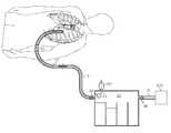
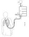
- FIGS. 1 a and 1 bare schematic perspective illustrations showing a medical tube (a chest tube is illustrated) for draining material from a patient, which is coupled to a drainage canister and ultimately to a suction source.
- a medical tubea chest tube is illustrated
- FIGS. 1 a and 1 bshow a clearance member at the end of a guide member for clearing obstructions from the medical tube, which is at different stages of actuation in the respective figures.
- the guide memberextends back into the drainage canister and is coupled to a guide-member actuator at or adjacent its proximal end.
- FIGS. 2 a and 2 bare close-up cross-sectional views of an embodiment of a guide-member actuator, shown in different stages of actuation corresponding respectively to the illustrations in FIGS. 1 a and 1 b.
- FIGS. 3 a - 3 dillustrate various embodiments of a clearance member disposed at the distal end of a guide member, as well as an embodiment of the guide member in the form of a guide wire having a core-and-sheath construction ( FIG. 3 d ).
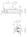
- FIG. 4is a perspective view, partially in section, of a guide member inserted in a chest tube, according to an embodiment hereafter described.
- FIG. 5is a side view, partially in section, of the distal region of a medical tube according to an embodiment hereafter described, which includes a clearance-member seat disposed at the distal end of the medical tube.
- FIG. 6is a perspective view of the distal region of a medical tube according to a further embodiment hereafter described, which includes a slot disposed in the inner wall of the medical tube that is adapted to house and accommodate the guide member as it translates along the axis of the medical tube.
- FIG. 7is a schematic side view, in section, illustrating an embodiment of a guide-member actuator as hereafter described.
- proximal and distalare generally to be construed with reference to a patient that has been or is to be fitted with a medical tube, such as a chest tube.
- a medical tubee.g. chest tube
- a distal elementor the distal side or region of an element
- a proximal elementor the proximal side or region of an element.
- the “terminal” end of a tube, wire or memberrefers to its distal end.
- FIG. 1shows a schematic representation of a medical tube being used to drain accumulated fluid from within the body cavity of a patient, in accordance with an exemplary embodiment of the invention.
- the medical tubeis inserted into and used to drain fluid from the chest cavity of the patient, and so is referred to as a chest tube 10 .
- Chest tubes 10are a common type of medical drain tube and the remaining description will be provided with reference to chest tubes 10 .
- the chest tube 10enters the patient through the chest-cavity (body) wall, so that its distal end is positioned within the chest (body) at a location from which fluid is to be drained.
- the proximal end of the chest tube 10remains outside the body.
- the chest tube 10can be inserted into the patient in a conventional manner, and positioned and secured in place through the chest-cavity wall by the physician.
- the proximal end of the chest tube 10is provided in fluid communication with a suction source 200 to draw fluid and other debris out from the chest tube 10 .
- the suction source 200also helps sustain the normal physiologic negative pressure within the chest of the patient.
- One or more drainage tubes 12 and/or drainage canisters 20may be disposed intermediate the chest tube 10 and suction source 200 , e.g. via a suction tube 13 , in fluid communication therewith to provide a suction pathway from the chest tube 10 to the suction source 200 .
- a drainage canisteris a container, vessel or other enclosure that defines a volume or fluid chamber for the accumulation of debris and other material from a human or animal patient, which is capable of being provided in fluid communication with a medical tube to at least in part define a sterile field therewith.
- the drainage canisterprovides a storage volume for drained fluid and debris and thereby serves two functions in the disclosed embodiments. First, the drainage canister 20 protects the suction source 200 from being damaged or contaminated by an influx of drained fluids and other materials and secretions from the patient. Second, the canister 20 permits the clinician to visualize the volume of material drained from the patient.
- a clearance member 14is normally disposed within the chest tube at or proximate its distal end as seen in FIG. 1 a .
- the clearance member 14is formed at or attached to the distal end of a guide member 16 that can be inserted into and through the chest tube 10 .
- the clearance member 14is drawn proximally, via guide member 16 , to catch and thereby also draw any such obstructions proximally through, and preferably out of, the chest tube 10 .
- the clearance member 14can be drawn substantially toward the drainage canister 20 , so that any obstructive materials mechanically engaged by the clearance member 14 can be drawn completely out of the chest tube 10 and any drainage tube 12 located between the chest tube and the canister 20 .
- the guide member 16extends from the canister 20 all the way through the chest tube 10 and any drainage tube 12 therebetween.
- the proximal end of the guide member 16is connected to a guide-member actuator 30 .
- the actuator 30is operable to actuate the guide member to reversibly withdraw the clearance member 14 from the distal end of the chest tube 10 , thereby drawing clot material or other obstructions proximally through or out of the chest tube, and thereafter to re-insert the clearance member 14 so that it is located at its resting position adjacent the chest tube's 10 distal end.
- the actuator 30is operable to draw the clearance member 14 all the way back to the drainage canister 20 , so that any obstructions carried out of the chest tube 10 by the clearance member are mechanically drawn all the way back to the canister.
- This embodimentmay be preferred to reduce the incidence of clot or other obstructive material being entrained in the drainage tube 12 after it is drawn out of the chest tube 10 .
- guide member 16is in the form of a guide wire.
- a guide member that is not a wirecan be used to reversibly advance the clearance member 14 through the suction pathway (defined herein) to clear debris.
- other guide members that can be substituted for the guide wire 16 described hereininclude an elongate flat metal or plastic strip, or other elongate form, that is flexible but biased to a straight configuration but capable to negotiate bends in the medical tube (such as chest tube 10 ) and any intermediate drainage tube(s) 12 that may be used.
- Still further embodiments of a guide member that could be substituted for the guide wire 16 described herein, which will be readily ascertained by those having ordinary skill in the art,can be used.
- the actuator 30includes a handle portion 32 having an endcap member 32 a , such as a disc member, and a handle 32 b attached to a surface of the endcap member 32 a .
- a flexible or collapsible sheath 34is attached at its first end to the endcap member 32 a and at its second end to the housing of the canister 20 , or to an actuator seat 36 that is formed with or attached to the housing as seen in the figures, surrounding an actuator port 22 through the housing wall of the canister 20 .
- the proximal end of the guide wire 16extends from the actuator port 22 and is attached to the endcap member 32 a within the sheath 34 .
- a wiping septumcan be provided in the port 22 through which the guide wire 16 passes as it is advanced or withdrawn via the actuator 30 .
- the sheath 34is sealingly attached at either end to the endcap member 32 a and the housing 20 (or optional seat 36 ) to protect the sterile field within the drainage canister 20 , the chest tube 10 and any associated drainage tubes 12 during actuation of the guide-wire actuator 30 to insert or withdraw the guide wire 16 as explained herein.
- the guide wire 16extends from the endcap member 32 a through the actuator port 22 in the canister 20 housing, then through drainage port 24 in the housing toward or through the chest tube 10 to manipulate the clearance member 14 disposed at its distal end.
- the actuator 30is shown in a first position wherein the guide wire 16 is inserted to its maximum extent into and through the canister 20 , and thereafter through the chest tube 10 .
- FIG. 2 b(corresponding to FIG.
- the actuator 30is shown in a second position wherein the handle 32 b and proximal end of the guide wire 16 are withdrawn to a maximum extent from the canister 20 housing, with a substantial length of the guide wire 16 being now accommodated within the volume of the expanded sheath 34 .
- the guide wire 16can be withdrawn so the clearance member 14 is retracted to a position just proximate the drainage tube 12 within the canister 20 .
- the clearance member 14can be retracted to a position just proximate the chest tube 10 within the drain tube 12 (not shown).
- the canister 20 and drainage tube 12can be supplied together, with the guide wire 16 in the fully-withdrawn position so that it and clearance member 14 initially are housed within the drainage tube 12 as-supplied.
- the drainage tube 12can be plugged to ensure the interior of the canister and drainage tube 12 (as well as the guide wire 16 and clearance member 14 ) remain sterile until use.
- the canister 20can be supplied with the chest tube 10 and optionally an intermediate drainage tube 12 all linked in fluid communication.
- the guide wire 16 and actuator 30can be supplied initially in the fully-inserted position with the clearance member 14 disposed within the chest tube 10 just inside its terminal end. This embodiment may be desirable because then the length of the guide wire 16 can be supplied to correspond precisely to the length of the chest tube 10 and any intermediate drainage tube 12 that will be used.
- the length of the sheath 34 in the fully-expanded statecan be selected beforehand so that it is supplied having a fully-expanded length that precisely corresponds to the length-extent to which guide wire 16 and clearance member 14 are to be permitted to be fully withdrawn. For example, if it is desired that the guide wire 14 can only be withdrawn from the chest tube 10 to a position just inside the drainage tube 12 proximal to the chest tube 10 , then the sheath's 34 fully-extended length can be selected to correspond to just over the length of the chest tube 10 .
- the chest tube 10is to be supplied already connected to the drainage canister 20 , together with the drainage canister 20 but not yet connected, or even separately, so long as the length of the chest tube 10 is known or is specified in the operating instructions that accompany the drainage canister 20 .
- the clearance member 14can be withdrawn through the chest tube 10 and any intermediate drainage tube 12 to just inside the drainage canister 20 , then the sheath's 34 fully-extended length can be selected to correspond to just greater than the sum of the lengths of the tubes 10 and 12 , either as-supplied with the drainage canister 20 or as otherwise specified.
- the canister 20can be supplied alone with the guide wire 16 fully withdrawn so that the clearance member 14 at its terminal end rests just within the fitting for attaching the drainage tube 12 or a chest tube 14 to the canister 20 . If the chest tube 10 (and intermediate drainage tube 12 , if present) are not supplied with the drainage canister 20 and their lengths are not specified, additional care may be necessary when using the actuator 30 to advance the guide wire 16 and clearance member 14 during use, because the extensible length of the guide wire 16 (or sheath 34 ) as-supplied may be greater than the lengths of the chest tube 14 and any intermediate drainage tube 12 that are to be connected thereto for use with a patient. It is contemplated that numerous different guide-wire lengths can be made available to correspond to a variety of chest-tube 10 and intermediate drainage-tube 12 combinations, which can be supplied either together with the canister 20 or separately.
- the length of the fully-expanded sheath 34is preferably selected to correspond to the length of the guide wire 16 that is to be accommodated therein in the fully-withdrawn condition.
- a biasing member 38can be provided to bias the actuator 30 in a normally-inserted ( FIG. 2 a ) or a normally-withdrawn ( FIG. 2 b ) position, depending on whether the guide wire 16 and clearance member 14 are to be normally positioned in the corresponding fully-inserted or fully-withdrawn position during use.
- the biasing member 38is such as to bias the guide-wire actuator 30 in the normally-inserted position of FIG. 2 a .
- an operatorgrasps the handle 32 b and draws it away from the canister 20 housing to thereby draw the guide wire 16 and clearance member 14 proximally through (and possibly out of) the chest tube 10 , against the biasing force of the biasing member 38 .
- the biasing force of the member 38draws the handle 32 b of the actuator 30 back toward the normally-inserted position illustrated in FIG. 2 a , collapsing the sheath 34 and resulting in re-insertion of the clearance member 14 into the chest tube 10 to its fully-inserted position.
- biasing member 38could be biased to the normally-withdrawn position. Such a biasing member 38 will resist pressing the handle 32 b toward the housing of canister 20 (and thereby insertion of the guide wire 16 ), and will bias the handle 32 (and guide wire 16 ) back to the withdrawn position once any insertion force has been removed.
- the biasing member 38preferably is a coiled spring.
- Coiled springscan be supplied in an expanded state where there is normally spacing between adjacent coils of the spring, wherein the spring will tend to resist compression and will re-expand after any compressive force has been removed. Such a spring would be useful to bias the guide-wire actuator 30 in a normally-withdrawn position.
- Coiled springscan also be supplied in a fully-compressed state, where adjacent coils of the spring are normally in physical contact, wherein the spring will tend to resist expansion and will re-compress after any expansive force has been removed. Such a spring would be useful to bias the guide-wire actuator 30 in a normally-inserted position.
- the springis seated in and preferably attached to an actuator seat 36 that is attached to the housing of the canister 20 , or otherwise formed therewith, which surrounds the actuator port 22 .
- the spring or other biasing member 38can contacted or be attached directly to the housing wall surrounding the port 22 , with no seat 36 or other distinct structure provided.
- the opposite end of the springis contacted or attached to the endcap member 32 a of the handle portion 32 .
- the flexible sheath 34surrounds the biasing member 38 as well as the portion of the guide wire extending from the port 22 .
- the biasing membercan be provided outside the sheath 34 , such that the sheath 34 only encloses the portion of the guide wire 16 extending from the actuator port 22 to maintain a sterile field (not shown).
- the suction pathwayis defined by the chest tube 10 , the canister 20 housing and any associated drainage tubes 12 and suction tubes 13 that are provided in-line between the chest tube 10 and the suction source 200 .
- the guide wire 16 and clearance member 14are not critical to the present invention.
- the guide wire 16 and clearance member 14may be constructed and configured as follows.
- the clearance member 14can be reversibly advanced into and through the chest tube 10 via advancement and withdrawal of the guide wire 16 to which it is attached to withdraw obstructive debris from the chest tube as described above (and further described below).
- the clearance member 14is preferably disposed in and secured to the distal region of the guide wire 16 , preferably at its distal end.
- the clearance member 14can be formed by the guide wire.
- the terminal end of the guide wirecan be wound to form a loop 124 a at its terminal end.
- FIG. 3 aillustrates one embodiment using a guide wire 16 where the terminal portion of the guide wire 16 is wound to form loop 124 a .
- a small amount of slack after forming the loop 124 a in this embodimentis wound tightly along the length of the wire 16 immediately proximal to the loop 124 a .
- the amount of slack to be so woundcan be, e.g., about or less than the diameter of the loop 124 a , or about or less than twice that diameter.
- the slackis preferably wound so that adjacent turnings of the slack over the guide wire 16 are immediately adjacent (preferably in or nearly in contact with) one another, and substantially fully in contact with the portion of the wire 16 over which they are wound.
- the slack in the wire 16 after forming loop 124 acan be soldered to the portion of the wire 16 immediately proximal to the loop 124 a at solder joint 125 .
- the slackcan be positioned parallel to the portion of the guide wire 16 to which it is to be soldered, as shown in FIG. 3 b .
- itmay be wound around the guide wire 16 and then soldered.
- the length of the slackcan be similar as described above with respect to FIG. 3 a .
- the slackis to be soldered in parallel to the wire 16 as seen in FIG.
- loop 124 ait is preferable that its length be about or less than one radius (1 ⁇ 2 the diameter) of the loop 124 a .
- the diameter of loop 124 ais preferably selected to substantially correspond to the diameter of the inner wall of the chest tube 10 in which the loop 124 a (clearance member 14 ) will be used, as described in more detail below.
- a mesh 124 b(seen schematically in FIG. 3 a ) can be provided extending across the diameter of the loop 124 a , having openings dimensioned to permit fluid to flow therethrough. In this embodiment, liquid-phase blood and other fluids will be permitted to pass through the mesh 124 b from the body cavity, into the chest tube 10 from the opening at its terminal end.
- the guide wire 16can be attached at the perimeter of the loop 124 a , and can be formed integrally with the loop 124 a . Alternatively, the guide wire 16 can be attached at the center of the loop 124 a via cross members 124 c as seen in FIG. 3 c . However, embodiments that include elements that obstruct the opening at the center of the loop 124 a (e.g. mesh 124 b or cross members 124 c ) are less preferred due to the potential to promote obstruction of the loop 124 a , e.g., by the formation of clot material attached to such elements.
- the loop 124 alies in a plane that is at a predetermined angle, for example 90°, to the longitudinal axis of the guide wire 16 at the point where the loop 124 a and guide wire 16 (e.g. the longitudinal expanse of the guide wire 16 if that wire is used to form the loop 124 a ) intersect.
- the precise anglemay be subject to some variance, for example due to flexure of the guide wire 16 and loop 124 a as they are advanced and/or drawn through the chest tube.
- the angle between the loop 124 a and guide wire 16is in the range of 75° to 105°, more preferably 80° to 100°, more preferably 85° to 95°.
- the guide wire 16can be made from conventional materials including plastics and metals. It is preferred that the guide wire 16 be made from a material having sufficient flexibility that it can reversibly bend to a radius of curvature of four centimeters, more preferably three centimeters, more preferably two centimeters or one centimeter, without snapping or substantially compromising its structural integrity. Suitable materials include nitinol, stainless steel and titanium-nickel alloys. In addition to being sufficiently flexible to negotiate bends in the chest tube 10 (or drainage tube 12 ) on being advanced/retracted therethrough, the guide wire 16 should have sufficient stiffness or rigidity to be pushed through accumulated clot material within either tube without kinking or being caused to double back on itself.
- the requisite flexibility to negotiate bends simultaneous with the requisite stiffness to be pushed through clot materialmay be achieved by biasing the flexible guide wire 16 to a generally straight (linear) configuration.
- Thiscan be achieved, for example, utilizing a core-and-sheath construction as illustrated in close-up view in FIG. 3 d .
- the guide wire 16includes a core wire 128 and a sheath wire having a smaller diameter than the core wire 128 wound around the core wire 128 to provide a spiral-wound wire sheath 129 .
- the wire sheath 129can be made from any suitable material, e.g., including the same or similar materials useful for the core wire, noted above.
- the wire sheath 129will tend to bias the guide wire 16 (including core wire 128 and sheath 129 ) into a straight or linear configuration, while still permitting the wire 16 to bend in order to traverse bends in the chest tube 10 when in use.
- the guide wire 16(including core wire 128 and sheath 129 ) still preferably can be bent to the radii of curvature noted above without snapping or substantially compromising its structural integrity.
- the sheath 129stops short of the distal end of the guide wire 16 , where the core wire 128 emerges unsheathed and is formed into the loop 124 a at its distal end. In the embodiment shown in FIG.
- the slack in the core wire 128 after forming loop 124 ais soldered to the portion of the core wire 128 immediately proximal to the loop 124 a at solder joint 125 , similar as in the embodiment described above with respect to FIG. 3 b .
- the loop 124 amay be formed from the complete core-and-sheath construction of guide wire 16 , wherein the sheath 129 continues around the loop 124 a .
- a separate clearance member 14may be secured at or in the vicinity of the distal end of the guide wire 16 , whether a sheath 129 is employed or not.
- the guide wire 16may be coated substantially along its length with a friction-reducing material, to help prevent agglomeration of debris (such as blood clots) to the guide wire, and also to assist in transitioning the guide wire around bends in a chest tube 10 where it is to be inserted.
- Suitable coating materials for this purposeinclude, e.g., Teflon (polytetrafluoroethylene) compositions, polyurethane compositions, other hydrophilic polymers, and other coatings, including coatings comprising therapeutic agents such as a heparin coating or antibiotic coating.
- a chest tubeis connected in fluid communication with a drainage canister 20 and a suction source 200 , with a clearance member 14 disposed in the chest tube 10 to clear debris therefrom.
- the clearance member 14is attached to or disposed in the distal region or at the distal end of a guide wire 16 .
- the chest tube 10 , intermediate drainage tube 12 and canister 20are provided in fluid communication with one another to define the suction pathway described above via fluid-tight connections or seals that are effective to maintain a sterile field within the suction pathway.
- Such connectionsmay include, for example, conventional barbed fittings as known in the art.
- the chest tube 10(or intermediate drainage tube 12 if present) is secured to a drainage port 24 that provides fluid communication with the interior of the canister 20 .
- the vacuum source 200is connected via a vacuum tube 13 to a vacuum port 26 of the canister 20 , which also provides fluid communication to the interior of the canister 20 .
- the drainage and vacuum ports 24 and 26are located distant from one another, and both preferably above the intended maximum liquid level in the canister for drainage.
- the guide wire 16extends from its proximal end attached to the actuator 30 through the drainage port 24 of the canister 20 , and into the chest tube 10 where the clearance member 14 is used to dislodge obstructive material. As explained above, the guide wire 16 is actuable via the guide-wire actuator 30 to reversibly insert and withdraw the clearance member 14 through the chest tube 10 to clear debris that has accumulated therein.
- the chest tube 10 and any intermediate drainage tube 12are made from materials having elastic properties, such as silicone, which will help ensure a fluid-tight seal because the tubes 10 , 12 will tend to contract over the barbs of barbed fittings.
- a flexible, elastic chest tube 10e.g. made from silicone, also will result in reduced discomfort for the patient compared to more rigid chest-tube materials, such as polypropylene or polyethylene. However, if desired these and other rigid materials may be used. Other elastic materials, including elastic thermoplastics, also may be used in place of silicone, if desired.
- the chest tube 10is made from a clear (i.e.
- the chest tube 10can be made of a soft material such as silicone to improve patient comfort, while the intermediate drainage tube 12 can be made of more rigid, less expensive materials including those described above.
- the chest tube 10can have one or a plurality of apertures 119 through the wall of the tube 10 in the distal region thereof, to assist in suctioning and drawing fluid located in the body cavity where the chest tube 10 is placed.
- the clearance member 14is dimensioned and oriented so that it cannot pass through the apertures 119 , to emerge laterally from the chest tube 10 .
- the diameter of the wire loop 124 a(or other clearance member 14 ) is too large to fit through the width of apertures 119 based on its orientation, which is fixed relative to the guide wire 16 .
- the length of apertures 119also be smaller than the loop 124 a diameter.
- the clearance member 14is in the form of a wire loop 124 a .
- the diameter of the wire loop 124 apreferably substantially corresponds to the inner diameter of the chest tube 10 , such that the loop 124 a scrapes the inner diameter 14 as it translates along the chest-tube 10 length.
- the diameter of the wire itself that forms the wire loop 124 ais very small, preferably about or less than 10%, preferably 8%, preferably 6%, preferably 5% or 4%, the inner diameter of the chest tube 10 , to provide a substantially unobstructed pathway from the distal end of the chest tube 10 into and through its chest tube 10 , through the loop 124 a .
- Fluid and other debris drained from the body cavitypass into the chest tube 10 , through the loop 124 a , and proceed proximally toward the suction source 200 .
- the fluidcan form or produce clots that stick to the inner wall of the chest tube 10 ( FIG. 1 a ).
- the clotsform or build, they begin to obstruct the chest tube 10 , inhibiting drainage. If left unchecked, such clots may completely obstruct the chest tube 10 , rendering the chest tube 10 inoperative.
- the clearance member 14(e.g. loop 124 a ) is normally disposed adjacent the distal end of the chest tube 10 inside the chest tube 10 .
- This position of the clearance member 14corresponds to the fully-inserted position of the guide-wire actuator 30 as illustrated in FIG. 2 a .
- a nurse, physician or other operatorgrasps the handle 32 b of the actuator 30 and pulls it away from the housing of canister 20 . This in turn draws the guide wire 16 , which also draws the clearance member 14 proximally through the chest tube 10 as seen in FIG. 1 b .
- the clearance member 14As the clearance member 14 is drawn proximally, it engages clot material and other debris in its path and forces such material and debris proximally, toward the drainage canister 20 . If desired, the operator can translate the clearance member 14 back-and-forth within the chest tube 10 (and optionally the drainage tube 12 ) through back-and-forth translation of the handle 32 b of the guide-wire actuator 30 toward and away from the drainage canister 20 . This may help break up clot material or other debris, as well as aid in drawing such debris proximally.
- the operatorcan re-insert the clearance member 14 to its resting position (assuming a normally-inserted configuration is used) by fully advancing the handle 32 b of the actuator 30 toward the canister 20 ( FIG. 2 a ). Such re-insertion may be effected or assisted by an appropriate biasing member 38 , if present, as explained above.
- the guide-wire actuator 30is to be in a normally-withdrawn position, so that in the parked position of the clearance member 14 is distant from the chest tube's 10 distal end, to clear debris from the chest tube 10 the handle 32 b of actuator 30 is pressed toward the canister 20 , thus compressing the sheath 34 and inserting the guide wire 16 and clearance member distally 14 through the chest tube 10 .
- the clearance memberis initially advanced distally so that it approaches the distal end of the chest tube 10 , preferably past any debris therein, before being withdrawn again proximally to draw debris out of the chest tube 10 .
- This embodimentis less preferred, because it may result in advancing debris out of the distal end of the chest tube 10 when the clearance member 14 is first advanced therein from its resting position.
- the inner diameter of the drainage tube 12can be larger than the inner diameter of the chest tube 10 .
- debris removed from the chest tube 10 and into the drainage tube 12will be less obstructive in the drainage tube 12 and more readily drawn out and into the canister 20 via suction applied by the suction source 200 .
- a drainage tube 12 that eventually becomes fully obstructedwill be more readily and easily replaced than a chest tube, which is surgically implanted through the patient's body wall and would require revision surgery, and additional opportunity for injury and infection, to replace. If the drainage tube 12 is to be replaced, requiring breaking the sterile field within the suction pathway, care should be taken to establish a sterile field around the breakage point (i.e. between the chest tube 10 and canister 20 ) when substituting a new drainage tube 12 .
- the chest tube 10can include a conical clearance-member seat 123 extending radially inward and in a proximal direction from the distal end of the chest tube 10 , within the chest-tube passageway 116 .
- a clearance member in the form of loop 124 ais seated at the distal end of the chest tube 10 after use, as by replacing the handle 32 b of the guide-wire actuator in the inserted position ( FIG. 2 a )
- the seat 123projects through the clearance-member loop 124 a , thereby dislodging any clot material that may be adhered to the loop 124 a .
- such a clearance-member seat 123may be less preferred due to a tendency to increase the incidence of clogging the entrance to chest tube 10 at the distal end of the chest tube 10 .
- the guide wire (or more generally guide member) 16can have a guide lumen 162 provided in fluid communication with one or more openings 164 disposed through the wall of the loop 124 a (or other clearance member 14 ).
- the guide lumen 162 and cooperating openings 164may be utilized to deliver flushing or irrigation fluid to assist in dislodging any material stuck to the clearance member loop 124 a .
- fluid expelled from guide lumen 162 through openings 164may be a solution provided to assist in the dislodgment, dissolution and/or breakup of the debris.
- a fluid portcan be provided in fluid communication therewith near the proximal end of the guide wire 16 , for example through the endcap member 32 a or through the sheath 34 (not shown).
- the fluid portcan have a conventional receiver on the outside to mate with a syringe or other fluid-delivery device, to communicate a fluid from the delivery device through the flexible tubing, and into and through the guide lumen 162 to emerge through openings 164 .
- Fluids suitable for the particular purposeinclude, but are not limited to, anti-thrombolytic agents, AlkalolTM, among others.
- such fluidmay be or include a therapeutic agent such as but not limited to antibiotic agents, anti-neoplastic agents, and other agents for a variety of purposes, including pain relief, treatment of infection, cancer, or to induce scarring (i.e. pleurodesis).
- a therapeutic agentsuch as but not limited to antibiotic agents, anti-neoplastic agents, and other agents for a variety of purposes, including pain relief, treatment of infection, cancer, or to induce scarring (i.e. pleurodesis).
- the guide lumen 162can be utilized to draw a vacuum at the openings 164 provided at the distal end of the guide wire 16 by applying a vacuum to the fluid port at the proximal end of the guide wire 16 .
- the guide lumen 162may be used to detect carbon dioxide in the chest cavity as a means to determine whether there is a puncture in a patient's lung.
- a CO 2 -sensing instrument or appropriate litmus paperthat can sense the presence of CO 2 , e.g. via a color change, can be connected in fluid communication with the aforementioned fluid port outside the guide-wire actuator 30 .
- This instrument/litmus papermay be provided outside the sterile field in communication with the fluid port or receiver mentioned above.
- CO 2 -sensing equipmentin communication with the lumen of the chest tube 10 to sense the presence of CO 2 in the chest tube.
- Thiscan be achieved, for example, by placing a CO 2 -sensor, such as a sensing transducer or a holder for CO 2 -sensitive litmus paper, in-line between the chest tube 10 and the suction source 200 , for example between the drainage tube 12 and chest tube 10 , or within the canister 20 , such as CO2-sensor 50 shown schematically in FIG. 7 .
- CO 2 passing from the chest tube 10 to the suction sourcewill pass through the CO 2 sensor, permitting the sensor to alarm if CO 2 is detected.
- the CO 2 sensormay be coupled to the chest tube lumen via a lateral channel in communication with the chest tube (not shown).
- a common size for a conventional chest tube 10is 32-French.
- the drainage tube 12 between the chest tube 10 and the drainage canister 20when used preferably is larger, so as to have a larger inner diameter, for example 30-French or 28-French.
- the drainage tube 12 intermediate the chest tube 12 and the drainage canister 20preferably has a larger inner diameter than the chest tube 10 , preferably at least two French sizes larger.
- the clearance loop 124 ais selected so that its loop diameter substantially corresponds with the inner-wall diameter of the chest tube 10 that is selected.
- the chest tube 10has a single inner lumen defined by its inner diameter, which has a circular cross-section.
- the inner surface of the chest tube 10 wallhas a substantially circular cross-section but also defines a slot 222 extending longitudinally along the length of the chest tube 10 , to accommodate the guide wire 16 therein.
- the guide wire 16terminates at its distal end in a modified loop 124 a whose shape preferably corresponds substantially to the cross-section of the inner surface of the chest tube 10 wall, having the slot 222 therein.
- This embodimentmay be desirable in applications where the chest tube 10 may undergo relatively sharp bends, so that the slot 222 , which houses the guide wire 16 , can help prevent buckling of the wire 16 on advancement thereof.
- the medical tubeneed not be a chest tube.
- the drainage canister 20 disclosed herein, having a guide-wire actuator 30 to controllably advance and withdraw the guide wire 16 and clearance member 14can be used in conjunction with other medical tubes used to provide fluid communication between a location within a human or animal body and an external apparatus or environment, either to drain fluid or other material from the body (e.g. chest tube, urinary catheter or other drainage tube) or to deliver material from outside the body (e.g. NG-tube or intubation tube).
- the medical tube(such as a chest tube 10 or other medical tube) can be provided with a lateral channel (or channels) for a variety of purposes, for example where it is desirable to have an additional access port into the medical tube, or into the body cavity where the distal end of the medical tube resides, such as to deliver medication.
- a medicationcan be delivered to the patient's body cavity by inserting a small catheter through the lateral channel in communication with the medical tube, and snaking the catheter up through the medical tube (e.g. chest tube 10 ) until it reaches or, if desired, just emerges from the distal end thereof.
- a syringe or other delivery device connected to the proximal end of the cathetercan be used to deliver the medication or other fluid through the catheter and into the body cavity where the distal end of the medical tube has been placed.
- the lateral channel in communication with such medical tubecan be sealed via a suitable closure, such as a conventional valve, stopcock or septum, to permit insertion of a catheter when desired while maintaining a sterile field within the suction pathway.
- a lateral channelmay be formed directly with the medical tube, or it may be provided in conjunction with an adapter disposed in-line with the suction pathway (such as a y-adapter placed between the tubes 12 and 14 , or between tube 12 / 14 and the canister 20 ).
- a guide wire manipulation devicecan be used to impart vibrations or other energy or motion to the guide wire, and consequently to the clearance member 14 located at its distal end.
- a manipulation devicecan comprise, for example, a sonic transducer 40 coupled to an ultrasonic wave guide 45 as seen schematically in FIGS. 2 a - 2 b .
- the sonic transducer or wave guidecan be or form part of or couple to the handle portion 32 of the guide-wire actuator 30 , to which the proximal end of the guide wire 16 is attached.
- energizing the transducerwill impart the corresponding vibrations or movement to the guide wire 16 , which will in turn be transmitted along the guide-wire length and to the clearance member 14 .
- sonic or other vibrations generated by the transducer at handle portion 32are conducted through the guide wire 16 and to the clearance member 14 , to induce sonic motion to that member (e.g. loop 124 a ) as well as any surrounding fluid, further assisting in the breakup and/or dislodgment of any foreign or obstructing material in the chest tube 10 .
- the transducercan impart other forms of energy, such as sub-sonic vibrations, acoustic pulses, or even full or partial (e.g.
- the handle 32 bpreferably is insulated from any such vibrations or motion to protect the operator, and also so the handle 32 b will not experience any such rotations or vibrations, which may inhibit its use by the operator.
- a suitable gasket or other vibration-damping materialcan be provided intermediate the handle 32 b and endcap member 32 a , or a rotatable joint can be provided therebetween, enabling the endcap member 32 a to rotate while the handle 32 b is held rotationally steady.
- the manipulation deviceBy coupling the transducer or wave guide of the manipulation device to the handle portion 32 of the guide-wire actuator 30 , the manipulation device can be operated outside the sterile field and will not compromise the sterile environment within the suction pathway when in use.
- FIGS. 2 a - 2 bthe description has been provided in connection with the embodiment of a guide-wire actuator 30 as seen in FIGS. 2 a - 2 b .
- numerous alternative embodiments of a guide-wire actuatorcould be employed and will become evident to persons of ordinary skill in the art who have reviewed this specification.
- FIG. 7an alternative embodiment guide-wire actuator 30 is illustrated in FIG. 7 .
- the proximal end of the guide wire 16is attached to a rotatable wheel or spindle 31 that is rotatably mounted inside the drainage canister 20 .
- the guide wire 16extends from its point of attachment to the spindle 31 , through the canister 20 housing, and through drainage tube 12 on its way to a chest tube 10 , wherein a clearance member 14 for clearing the chest tube 10 of debris is secured or formed at the distal end (or in the distal region) of the guide wire 16 .
- a hand-crank 33is rotationally coupled to the spindle 31 through the housing wall of canister 20 , such that an operator can manually rotate the spindle 31 to wind or unwind slack of the guide wire 16 therearound. As will be appreciated, this will have the effect to advance or withdraw the guide wire 16 from the chest tube 10 /drainage tube 12 , thereby actuating the clearance member to remove debris as already described.
- a torsion spring(not shown) can be utilized to bias the spindle 31 in one rotational direction or the other as desired, to provide either a normally-inserted or a normally-withdrawn guide wire 16 /clearance member 14 as may be desired.
- an appropriate rotation-stopcan be incorporated to ensure the spindle 31 does not rotate too far in one or the other direction, for example so that the guide wire 16 cannot be completely withdrawn into the drain canister.
- the rotational linkage through the housing wall between spindle 31 and crank 33is provided so as to ensure and maintain the sterility of the drain canister 20 and suction pathway.
- the guide-wire actuator 30can include other mechanical structure to advance and/or withdraw the guide wire 16 through the drainage port 24 .
- the handle portion 32 in the embodiment of FIGS. 1 and 2may be replaced with a foot pedal coupled to the proximal end of the guide wire 16 to draw it out of the actuator port 22 .
- Appropriate pulleyscan be used, as known in the art, to string the guide wire 16 along an appropriate path depending on the geometry and location of the pedal structure, which is well within the ability of a person having ordinary skill in the art.
- the drainage canistermay include a trolley coupled to the proximal end of the guide wire, which is housed within the canister 20 .
- the trolleycan be slidably mounted or coupled to a side wall of the canister, within the interior of canister 20 , and be adapted to translate along the canister wall in a vertical or other direction.
- This trolleymay be coupled to a foot pedal, handle or other mechanism through the canister wall in a manner so as to ensure the sterility of the interior environment.
- the trolleythen can be actuated to reversibly advance or withdraw the guide wire 16 through the drainage port 24 as already described.
- other wind-up mechanismsbeyond that illustrated in FIG. 7 and described above might be used.
- torsion springs or other biasing memberscan be incorporated so that once a catch is released a winding or rotating element is caused to automatically rotate until it contacts or actuates a stop to cease its rotation or winding of the guide wire 16 (similar to a window shade roller).
- the actuator 30may comprise or be coupled to a mechanism to automatically actuate the guide wire/clearance member to remove debris from the chest tube 10 (or other medical tube) according to a fixed schedule, such as every 30 minutes, every hour, or another selected time interval.
Landscapes
- Health & Medical Sciences (AREA)
- Surgery (AREA)
- Engineering & Computer Science (AREA)
- Life Sciences & Earth Sciences (AREA)
- Biomedical Technology (AREA)
- Pathology (AREA)
- Oral & Maxillofacial Surgery (AREA)
- Nuclear Medicine, Radiotherapy & Molecular Imaging (AREA)
- Mechanical Engineering (AREA)
- Heart & Thoracic Surgery (AREA)
- Medical Informatics (AREA)
- Molecular Biology (AREA)
- Animal Behavior & Ethology (AREA)
- General Health & Medical Sciences (AREA)
- Public Health (AREA)
- Veterinary Medicine (AREA)
- External Artificial Organs (AREA)
Abstract
Description
Claims (33)
Priority Applications (3)
| Application Number | Priority Date | Filing Date | Title |
|---|---|---|---|
| US12/425,078US8246752B2 (en) | 2008-01-25 | 2009-04-16 | Methods and devices to clear obstructions from medical tubes |
| EP09808547.5AEP2328632B1 (en) | 2008-08-22 | 2009-06-02 | Methods and devices to clear obstructions from medical tubes |
| PCT/US2009/045954WO2010021775A1 (en) | 2008-08-22 | 2009-06-02 | Methods and devices to clear obstructions from medical tubes |
Applications Claiming Priority (4)
| Application Number | Priority Date | Filing Date | Title |
|---|---|---|---|
| US2382908P | 2008-01-25 | 2008-01-25 | |
| US18985008P | 2008-08-22 | 2008-08-22 | |
| US12/359,826US7951243B2 (en) | 2008-01-25 | 2009-01-26 | Methods and devices to clear obstructions from medical tubes |
| US12/425,078US8246752B2 (en) | 2008-01-25 | 2009-04-16 | Methods and devices to clear obstructions from medical tubes |
Related Parent Applications (1)
| Application Number | Title | Priority Date | Filing Date |
|---|---|---|---|
| US12/359,826Continuation-In-PartUS7951243B2 (en) | 2008-01-25 | 2009-01-26 | Methods and devices to clear obstructions from medical tubes |
Publications (2)
| Publication Number | Publication Date |
|---|---|
| US20090264833A1 US20090264833A1 (en) | 2009-10-22 |
| US8246752B2true US8246752B2 (en) | 2012-08-21 |
Family
ID=41707400
Family Applications (1)
| Application Number | Title | Priority Date | Filing Date |
|---|---|---|---|
| US12/425,078Active2030-08-11US8246752B2 (en) | 2008-01-25 | 2009-04-16 | Methods and devices to clear obstructions from medical tubes |
Country Status (3)
| Country | Link |
|---|---|
| US (1) | US8246752B2 (en) |
| EP (1) | EP2328632B1 (en) |
| WO (1) | WO2010021775A1 (en) |
Cited By (16)
| Publication number | Priority date | Publication date | Assignee | Title |
|---|---|---|---|---|
| WO2016094548A1 (en)* | 2014-12-10 | 2016-06-16 | Mayo Foundation For Medical Education And Research | Co2-sensing chest tube and needle thoracostomy devices |
| WO2017031185A1 (en)* | 2015-08-17 | 2017-02-23 | Musc Foundation For Research Development | Suction de-clogger system and method |
| US9604033B2 (en) | 2014-06-27 | 2017-03-28 | Harrison M. Lazarus | Body cavity drainage devices with locking devices and related methods |
| US9649415B2 (en) | 2014-06-27 | 2017-05-16 | Harrison M. Lazarus | Surgical kits for body cavity drainage and related methods |
| US9821097B2 (en) | 2014-06-27 | 2017-11-21 | Merit Medical Systems, Inc. | Body cavity drainage devices including drainage tubes having inline portions and related methods |
| US10029036B2 (en) | 2014-06-27 | 2018-07-24 | Merit Medical Systems, Inc. | Placement tools for body cavity drainage devices and related methods |
| WO2018175431A1 (en) | 2017-03-20 | 2018-09-27 | Penumbra, Inc. | Methods and apparatus for removal of intracranial hemorrhage |
| US10232150B2 (en) | 2010-03-11 | 2019-03-19 | Merit Medical Systems, Inc. | Body cavity drainage devices and related methods |
| US10286183B2 (en) | 2015-11-25 | 2019-05-14 | Merit Medical Systems, Inc. | Steerable sheath catheter and methods of use |
| US10335524B2 (en) | 2014-01-07 | 2019-07-02 | Mayo Foundation For Medical Education And Research | Portable chest tube pressure and CO2 monitor |
| US10471189B2 (en) | 2014-02-17 | 2019-11-12 | Clearflow, Inc. | Medical tube clearance device |
| US10525175B2 (en) | 2015-08-28 | 2020-01-07 | Epic Medical Concepts & Innovations, Inc. | System for clearing surgical chest drainage tube blockages |
| US10918769B2 (en)* | 2017-04-03 | 2021-02-16 | Boehringer Technologie, LP | Medical drainage device with squeegee-based lumen cleaner and method of draining a biological fluid from the body of a patient |
| US10974023B2 (en) | 2014-02-17 | 2021-04-13 | Clearflow, Inc. | Medical tube clearance |
| US11559662B2 (en) | 2018-04-13 | 2023-01-24 | Merit Medical Systems, Inc. | Steerable drainage devices |
| US11925745B1 (en)* | 2019-11-27 | 2024-03-12 | Clearflow, Inc. | Clearance system for medical tubes such as surgical drains |
Families Citing this family (28)
| Publication number | Priority date | Publication date | Assignee | Title |
|---|---|---|---|---|
| US8262645B2 (en) | 2007-11-21 | 2012-09-11 | Actuated Medical, Inc. | Devices for clearing blockages in in-situ artificial lumens |
| US9352122B2 (en) | 2007-11-21 | 2016-05-31 | Actuated Medical, Inc. | Devices for clearing blockages in small bore in-situ artificial lumens |
| US9308348B2 (en) | 2007-11-21 | 2016-04-12 | Actuated Medical, Inc. | Devices and methods for clearing occlusions and for providing irrigation in in-situ artificial and natural lumens |
| WO2009120400A2 (en) | 2008-01-25 | 2009-10-01 | Clear Catheter Systems, Llc | Methods and devices to clear obstructions from medical tubes |
| US8882678B2 (en) | 2009-03-13 | 2014-11-11 | Atrium Medical Corporation | Pleural drainage system and method of use |
| CN102319706A (en)* | 2011-05-07 | 2012-01-18 | 李林风 | Indwelling catheter embolism clearing device based on negative pressure suction principle |
| CA2883616C (en) | 2011-08-25 | 2020-07-21 | H & M Innovations, Llc | Anti-clog suction tip apparatus and methods |
| US8845618B2 (en) | 2011-08-25 | 2014-09-30 | H & M Innovations, Llc | Anti-clog suction tip apparatus and method |
| US9302031B2 (en) | 2011-11-22 | 2016-04-05 | Cook Medical Technologies Llc | Tubular drainage device |
| US9707325B2 (en) | 2011-12-02 | 2017-07-18 | Cook Medical Technologies Llc | Drainage system with occlusion member |
| US9561337B2 (en) | 2012-10-11 | 2017-02-07 | Actuated Medical, Inc. | Active system for in-situ clearing of secretions and occlusions in tubes |
| US20160001036A1 (en)* | 2013-02-26 | 2016-01-07 | Mayo Foundation For Medical Education And Research | Medical drainage tube obstruction extractor |
| US11191886B2 (en) | 2013-06-14 | 2021-12-07 | The Cleveland Clinic Foundation | Motion-assisted systems, devices and methods for minimizing obstruction of medical devices |
| US10391285B2 (en)* | 2013-06-14 | 2019-08-27 | The Cleveland Clinic Foundation | Motion-assisted systems, devices and methods for minimizing obstruction of medical devices |
| US9545462B2 (en)* | 2013-12-20 | 2017-01-17 | Northwestern University | Chest tube drainage system with analyzer |
| US10258764B2 (en)* | 2014-07-30 | 2019-04-16 | Covidien Lp | Opening system for improving catheter delivery |
| EP3072541A1 (en)* | 2015-03-27 | 2016-09-28 | Region Syddanmark | An improved chest drainage system and method |
| AU2016261628B2 (en)* | 2015-05-13 | 2020-11-05 | Atrium Medical Corporation | Chest drainage system |
| GB2557500B8 (en)* | 2015-07-29 | 2021-02-17 | Actuated Medical Inc | Devices for clearing blockages in artificial and natural lumens |
| DE112016004770T5 (en) | 2015-10-19 | 2018-07-12 | Actuated Medical, Inc. | Device for the in-situ cleaning of occlusions in hoses |
| US11147944B2 (en) | 2015-10-19 | 2021-10-19 | Actuated Medical, Inc. | Handset for occlusion clearing device |
| US11596726B2 (en)* | 2016-12-17 | 2023-03-07 | C.R. Bard, Inc. | Ultrasound devices for removing clots from catheters and related methods |
| CN111918689B (en)* | 2018-02-02 | 2023-05-19 | 麦克罗博医疗公司 | implantable catheter assembly |
| CN108434581A (en)* | 2018-04-25 | 2018-08-24 | 张家港市中医医院 | A kind of ditube drainage device |
| EP3603720B1 (en)* | 2018-07-31 | 2022-03-09 | CaDo Medial Solutions GmbH | Catheter desobstruction apparatus and system |
| CN116547031B (en) | 2020-11-17 | 2025-05-13 | 科里福罗公司 | Medical tube cleaning device |
| CN114432513A (en)* | 2022-01-25 | 2022-05-06 | 中国人民解放军联勤保障部队第九八八医院 | Medical oncology prevents blockking up drainage tube |
| US20240424187A1 (en)* | 2023-06-22 | 2024-12-26 | James William Klena | Multi-position modular carbon dioxide detector and indicator and methods of use |
Citations (195)
| Publication number | Priority date | Publication date | Assignee | Title |
|---|---|---|---|---|
| US3416532A (en) | 1964-07-24 | 1968-12-17 | Grossman Alan Richard | Drainage tube with means for scraping away debris therewithin |
| US3855208A (en) | 1971-05-24 | 1974-12-17 | Becton Dickinson Co | Derivatives of digoxigenin |
| US3946741A (en) | 1974-12-09 | 1976-03-30 | Adair Edwin Lloyd | Urethral catheter and body drainage device |
| US3957054A (en) | 1973-09-26 | 1976-05-18 | Mcfarlane Richard H | Surgical drainage tube |
| US3991762A (en) | 1974-09-30 | 1976-11-16 | Radford F Richard | Aspirating device for patient ventilation apparatus |
| US4006743A (en) | 1973-01-15 | 1977-02-08 | The Johns Hopkins University | System for continuous withdrawal of blood |
| US4056104A (en) | 1976-01-15 | 1977-11-01 | Burton Jaffe | Endotracheal tube |
| US4148319A (en) | 1976-12-29 | 1979-04-10 | Kasper Richard F | Urinary retention catheter |
| US4228802A (en) | 1977-06-15 | 1980-10-21 | Medical Products Institute Incorporated | Self-inflating and self-cleaning catheter assembly |
| US4257422A (en) | 1979-03-14 | 1981-03-24 | Minnesota Mining And Manufacturing Company | Surgical drain |
| US4317452A (en) | 1980-02-04 | 1982-03-02 | C. R. Bard, Inc. | Body fluid drain |
| US4324262A (en) | 1979-01-02 | 1982-04-13 | University Of Virginia Alumni Patents Foundation | Aspirating culture catheter and method of use |
| US4325961A (en) | 1977-06-01 | 1982-04-20 | Merck & Co., Inc. | Fluorinated amino acids |
| US4358434A (en) | 1979-12-19 | 1982-11-09 | New England Nuclear Corporation | Method, composition and kit for stabilizing radiolabeled compounds |
| US4390517A (en) | 1979-12-19 | 1983-06-28 | New England Nuclear Corporation | Method, composition and kit for stabilizing radiolabeled compounds |
| US4429693A (en) | 1980-09-16 | 1984-02-07 | Blake L W | Surgical fluid evacuator |
| US4445897A (en) | 1981-06-09 | 1984-05-01 | Ekbladh Fred V G | Catheter for postsurgical drainage |
| US4465481A (en) | 1981-02-26 | 1984-08-14 | Innovative Surgical Products, Inc. | Single piece wound drain catheter |
| US4483870A (en) | 1978-07-24 | 1984-11-20 | Merck & Co., Inc. | α-Difluoromethyl amino acids and hypertension treating compositions thereof |
| US4523920A (en) | 1983-12-05 | 1985-06-18 | Sil-Fab Corporation | Surgical suction drain |
| US4569344A (en) | 1984-07-23 | 1986-02-11 | Ballard Medical Products | Aspirating/ventilating apparatus and method |
| US4692153A (en) | 1986-04-03 | 1987-09-08 | Berlin Richard B | Surgical wound drain device |
| US4695588A (en) | 1977-06-01 | 1987-09-22 | Merck & Co., Inc. | Fluorinated amino acids |
| US4696296A (en) | 1984-07-23 | 1987-09-29 | Ballard Medical Products | Aspirating/ventilating apparatus |
| US4698058A (en) | 1985-10-15 | 1987-10-06 | Albert R. Greenfeld | Ultrasonic self-cleaning catheter system for indwelling drains and medication supply |
| US4706671A (en) | 1985-05-02 | 1987-11-17 | Weinrib Harry P | Catheter with coiled tip |
| US4723549A (en) | 1986-09-18 | 1988-02-09 | Wholey Mark H | Method and apparatus for dilating blood vessels |
| US4728319A (en) | 1986-03-20 | 1988-03-01 | Helmut Masch | Intravascular catheter |
| US4743691A (en) | 1977-07-11 | 1988-05-10 | Merrell Dow France Et Cie | 2-halomethyl derivatives of 2-amino acids |
| US4760091A (en) | 1985-10-01 | 1988-07-26 | The Dow Chemical Company | Method of controlling phytopathogenic fungus |
| US4762125A (en) | 1986-03-07 | 1988-08-09 | The University Of Texas System | Balloon-tipped suction catheter |
| US4771772A (en) | 1982-08-09 | 1988-09-20 | Medtronic, Inc. | Robotic implantable medical device and/or component restoration system |
| US4781678A (en) | 1986-03-06 | 1988-11-01 | Imtec S.A. | Surgical drain |
| US4865586A (en) | 1987-09-21 | 1989-09-12 | Martha Hedberg | Suction stylet for endotracheal intubation |
| US4865030A (en) | 1987-01-21 | 1989-09-12 | American Medical Systems, Inc. | Apparatus for removal of objects from body passages |
| US4889106A (en) | 1987-11-13 | 1989-12-26 | Kabushiki Kaisha Machida Seisakusho | Treating instrument for endoscope |
| US4909781A (en) | 1988-04-08 | 1990-03-20 | Husted Royce Hill | Catheter with flexible cutter |
| US4921488A (en) | 1988-01-15 | 1990-05-01 | Maitz Carlos A | Aspirator device for body fluids |
| US4942231A (en) | 1984-05-24 | 1990-07-17 | Mallinckrodt, Inc. | Method of preparing a chlorinated, brominated, radio-brominated, iodinated and/or radioiodinated aromatic or heteroaromatic compound |
| US4950232A (en) | 1987-08-11 | 1990-08-21 | Surelab Superior Research Laboratories | Cerebrospinal fluid shunt system |
| US4967743A (en) | 1987-03-11 | 1990-11-06 | Ballard Medical Products | Neonatal closed system for involuntary aspiration and ventilation, and method |
| US5009659A (en) | 1989-10-30 | 1991-04-23 | Schneider (Usa) Inc. | Fiber tip atherectomy catheter |
| US5062835A (en) | 1988-01-15 | 1991-11-05 | Maitz Carlos A | Aspirator device for body fluids |
| US5073164A (en) | 1990-05-02 | 1991-12-17 | Hollister William H | Suction catheter |
| USD328790S (en) | 1988-10-05 | 1992-08-18 | Atrium Medical Corporation | Chest drain vessel |
| US5141503A (en)* | 1991-01-29 | 1992-08-25 | Sewell Jr Frank K | Wound suction drainage system |
| US5188618A (en) | 1991-05-03 | 1993-02-23 | Thomas Bruce W | Thrombus-mobilizing thoracostomy tube |
| US5215522A (en) | 1984-07-23 | 1993-06-01 | Ballard Medical Products | Single use medical aspirating device and method |
| US5227467A (en) | 1987-08-03 | 1993-07-13 | Merck & Co., Inc. | Immunosuppressive fluorinated cyclosporin analogs |
| US5240675A (en) | 1992-09-24 | 1993-08-31 | Wilk Peter J | Method for cleaning endoscope |
| USD340285S (en) | 1990-11-08 | 1993-10-12 | Atrium Medical Corporation | Chest drain |
| US5260020A (en) | 1992-09-17 | 1993-11-09 | Wilk Peter J | Method and apparatus for catheter sterilization |
| US5261877A (en) | 1991-07-22 | 1993-11-16 | Dow Corning Wright | Method of performing a thrombectomy procedure |
| US5279812A (en) | 1989-10-03 | 1994-01-18 | Merrell Dow Pharmaceuticals Inc. | Radiolabeled anticoagulant peptides |
| WO1994003226A1 (en) | 1992-07-30 | 1994-02-17 | Dar Società Per Azioni | Device for the internal cleaning and clearing of tubular bodies for medical use which are insertable in human bodies |
| US5297310A (en) | 1993-01-21 | 1994-03-29 | Dennis Cox | Cleaning brush for endoscopes |
| US5310912A (en) | 1992-02-25 | 1994-05-10 | Research Biochemicals Limited Partnership | Iodinated neuroprobe for mapping monoamine reuptake sites |
| US5324504A (en) | 1989-07-31 | 1994-06-28 | The Johns Hopkins University | Perfluoro-t-butyl-containing compounds for use in fluorine-19 NMR and/or MRI |
| US5336177A (en) | 1993-04-29 | 1994-08-09 | Marcus William Y | Integral penetrating surgical drain device |
| US5349950A (en) | 1992-10-28 | 1994-09-27 | Smiths Industries Medical Systems, Inc. | Suction catheter assemblies |
| US5370610A (en) | 1993-02-09 | 1994-12-06 | Reynolds; James R. | Surgical drainage tube system |
| US5413779A (en) | 1990-08-09 | 1995-05-09 | Research Triangle Institute | Cocaine receptor binding ligands |
| US5490503A (en) | 1994-04-29 | 1996-02-13 | Smiths Industries Medical Systems, Inc. | Suction catheter having multiple valves and collet assembly |
| US5505713A (en) | 1994-04-01 | 1996-04-09 | Minimed Inc. | Indwelling catheter with stable enzyme coating |
| US5514112A (en) | 1992-10-02 | 1996-05-07 | Boston Scientific Corporation | Drainage catheter and method of use |
| US5520635A (en) | 1994-12-16 | 1996-05-28 | Gelbfish; Gary A. | Method and associated device for removing clot |
| US5522801A (en) | 1995-01-18 | 1996-06-04 | Wang; Abe | Integrate-forming silicone balloon catheter |
| US5536248A (en) | 1992-05-11 | 1996-07-16 | Arrow Precision Products, Inc. | Method and apparatus for electrosurgically obtaining access to the biliary tree and placing a stent therein |
| US5599299A (en) | 1992-05-11 | 1997-02-04 | Arrow Precision Products, Inc. | Multi-lumen endoscopic catheter |
| US5599300A (en) | 1992-05-11 | 1997-02-04 | Arrow Precision Products, Inc. | Method for electrosurgically obtaining access to the biliary tree with an adjustably positionable needle-knife |
| US5630823A (en) | 1994-06-17 | 1997-05-20 | William Cook Europe A/S | Apparatus for fragmentation of a lung or heart embolus |
| US5637759A (en) | 1992-07-30 | 1997-06-10 | The Regents Of The University Of California | Metal-ligating amino acid derivatives for MRI and for peptide synthesis |
| US5653696A (en) | 1984-05-14 | 1997-08-05 | Surgical Systems & Instruments, Inc. | Stent unclogging method |
| US5688234A (en) | 1996-01-26 | 1997-11-18 | Cardiometrics Inc. | Apparatus and method for the treatment of thrombotic occlusions in vessels |
| US5693011A (en) | 1995-04-27 | 1997-12-02 | Surgical Dynamics, Inc. | Surgical suction cutting instrument |
| US5698179A (en) | 1992-02-25 | 1997-12-16 | Neuro Imaging Technologies, Llc | Iodinated neuroprobe for mapping monoamine reuptake sites |
| US5715815A (en) | 1995-03-28 | 1998-02-10 | Ballard Medical Products, Inc. | Sheath sterility preservation filter and seal for suction catheters |
| US5768741A (en) | 1996-09-27 | 1998-06-23 | Leiman; Basil C. | Flexible pipe cleaning device and system |
| US5772261A (en) | 1995-07-21 | 1998-06-30 | The Nemours Foundation | Cannula connector and method of connecting medical tubes |
| US5773614A (en) | 1995-04-03 | 1998-06-30 | Bristol-Myers Squibb Co. | Process for the preparation of an antiviral agent |
| US5788681A (en) | 1992-05-11 | 1998-08-04 | Medical Innovations Corporation | Multi-lumen endoscopic catheter |
| US5788710A (en) | 1996-04-30 | 1998-08-04 | Boston Scientific Corporation | Calculus removal |
| US5807330A (en) | 1996-12-16 | 1998-09-15 | University Of Southern California | Angioplasty catheter |
| US5808146A (en) | 1995-11-09 | 1998-09-15 | Emory University | Amino acid analogs for tumor imaging |
| US5830127A (en) | 1996-08-05 | 1998-11-03 | Cybersonics, Inc. | Method and apparatus for cleaning endoscopes and the like |
| US5853696A (en) | 1993-10-25 | 1998-12-29 | Organix, Inc. | Substituted 2-carboxyalkyl-3(fluorophenyl)-8-(3-halopropen-2-yl) nortropanes and their use as imaging agents for neurodegenerative disorders |
| US5895398A (en) | 1996-02-02 | 1999-04-20 | The Regents Of The University Of California | Method of using a clot capture coil |
| US5897534A (en) | 1996-08-29 | 1999-04-27 | Team Medical, Llc | Body fluids and solids drainage system |
| US5902314A (en) | 1998-01-22 | 1999-05-11 | Koch; Craig S. | Medical instrument for removing lumen obstructions |
| US5911734A (en) | 1997-05-08 | 1999-06-15 | Embol-X, Inc. | Percutaneous catheter and guidewire having filter and medical device deployment capabilities |
| US5911710A (en) | 1997-05-02 | 1999-06-15 | Schneider/Namic | Medical insertion device with hemostatic valve |
| US5913852A (en) | 1995-07-21 | 1999-06-22 | Nemours Foundation | Drain cannula |
| US5921952A (en) | 1997-08-14 | 1999-07-13 | Boston Scientific Corporation | Drainage catheter delivery system |
| US5928218A (en) | 1994-12-16 | 1999-07-27 | Gelbfish; Gary A. | Medical material removal method and associated instrumentation |
| US5931821A (en) | 1996-03-05 | 1999-08-03 | Tyco Group S.A.R.L. | Chest drainage unit with controlled automatic excess negativity relief feature |
| US5964223A (en) | 1994-06-17 | 1999-10-12 | Trudell Medical Limited | Nebulizing catheter system and methods of use and manufacture |
| US5989241A (en) | 1995-11-24 | 1999-11-23 | Manan Medical Products, Inc. | Drainage catheter apparatus |
| US6045623A (en) | 1997-04-24 | 2000-04-04 | Cannon; Bradley Jay | Method and apparatus for cleaning catheter lumens |
| US6080170A (en) | 1996-07-26 | 2000-06-27 | Kensey Nash Corporation | System and method of use for revascularizing stenotic bypass grafts and other occluded blood vessels |
| US6082361A (en) | 1997-09-12 | 2000-07-04 | Morejon; Orlando | Endotracheal tube cleaning apparatus |
| US6096874A (en) | 1990-10-01 | 2000-08-01 | Board Of Regents, The University Of Texas System | High affinity tamoxifen derivatives |
| US6129697A (en) | 1990-08-06 | 2000-10-10 | Possis Medical, Inc. | Thrombectomy and tissue removal device |
| US6168603B1 (en) | 1995-02-02 | 2001-01-02 | Boston Scientific Corporation | Surgical extractor |
| US6183450B1 (en) | 1999-06-04 | 2001-02-06 | William A Lois | Catheter de-clogging device |
| US6245326B1 (en) | 1997-06-30 | 2001-06-12 | Sigma Pharmaceuticals Pty. Ltd. | Health supplement |
| US6248100B1 (en) | 1997-08-14 | 2001-06-19 | Scimed Life Systems, Inc. | Drainage catheter delivery system |
| US20010018572A1 (en) | 1998-10-16 | 2001-08-30 | Kinsey P. Spencer | Releasable locking needle assembly with optional release accessory therefor |
| US6299604B1 (en) | 1998-08-20 | 2001-10-09 | Cook Incorporated | Coated implantable medical device |
| US6344179B1 (en) | 1999-04-22 | 2002-02-05 | Emory University | Fluoralkenyl nortropanes |
| US20020058915A1 (en) | 1999-09-22 | 2002-05-16 | Akio Wakabayashi | Portable modular chest drainage system |
| US6399042B1 (en) | 1999-04-26 | 2002-06-04 | Emory University | 4-fluoroalkyl-3-halophenyl nortropanes |
| US20020099184A1 (en) | 1999-04-26 | 2002-07-25 | Goodman Mark M. | 4-Haloethenyphenyl tropane:serotonin transporter imaging agents |
| US20020128601A1 (en) | 1995-08-25 | 2002-09-12 | Reilly David M. | Front load pressure jacket system with syringe holder |
| US6454775B1 (en) | 1999-12-06 | 2002-09-24 | Bacchus Vascular Inc. | Systems and methods for clot disruption and retrieval |
| US6508789B1 (en) | 2000-06-05 | 2003-01-21 | Merit Medical Systems, Inc. | Systems and methods for coupling a drainage catheter to a patient and decoupling the drainage catheter from the patient |
| US6514273B1 (en) | 2000-03-22 | 2003-02-04 | Endovascular Technologies, Inc. | Device for removal of thrombus through physiological adhesion |
| US20030069551A1 (en) | 2001-10-05 | 2003-04-10 | Axiom Medical, Inc. | Multipurpose drain |
| US6547761B2 (en) | 2000-01-07 | 2003-04-15 | Scimed Life Systems, Inc. | Drainage catheter |
| US6582400B1 (en) | 2000-10-24 | 2003-06-24 | Scimed Life Systems, Inc. | Variable tip catheter |
| US6629956B1 (en) | 1997-03-26 | 2003-10-07 | John M. Polidoro | Parenteral fluid transfer apparatus |
| US6638253B2 (en) | 2001-07-17 | 2003-10-28 | Eugene Michael Breznock | Method and apparatus for chest drainage |
| US20030216760A1 (en) | 2002-05-20 | 2003-11-20 | Eric Welch | Apparatus and system for removing an obstruction from a lumen |
| US6663650B2 (en) | 2000-06-29 | 2003-12-16 | Concentric Medical, Inc. | Systems, methods and devices for removing obstructions from a blood vessel |
| US20040006331A1 (en) | 2002-07-04 | 2004-01-08 | Semyon Shchervinsky | Drain catheters |
| US6679262B1 (en) | 1996-03-11 | 2004-01-20 | Orlando Morejon | Endotracheal tube cleaning apparatus |
| US6692459B2 (en) | 2000-07-18 | 2004-02-17 | George P. Teitelbaum | Anti-occlusion catheter |
| US6699331B1 (en) | 1998-08-20 | 2004-03-02 | Novapharm Research (Australia) Pty Ltd | Endoscope cleaning device |
| US6702830B1 (en) | 1999-09-17 | 2004-03-09 | Bacchus Vascular, Inc. | Mechanical pump for removal of fragmented matter and methods of manufacture and use |
| US20040073243A1 (en) | 2000-06-29 | 2004-04-15 | Concentric Medical, Inc., A Delaware Corporation | Systems, methods and devices for removing obstructions from a blood vessel |
| US20040078026A1 (en) | 2002-10-21 | 2004-04-22 | Wagner Robert B. | Method and apparatus for pleural drainage |
| US6730104B1 (en) | 2000-06-29 | 2004-05-04 | Concentric Medical, Inc. | Methods and devices for removing an obstruction from a blood vessel |
| US20040092956A1 (en) | 2000-11-03 | 2004-05-13 | John Liddicoat | Catheter for removal of solids from surgical drains |
| US6740096B2 (en) | 2002-01-16 | 2004-05-25 | Scimed Life Systems, Inc. | Treatment and removal of objects in anatomical lumens |
| US6783536B2 (en) | 2001-12-14 | 2004-08-31 | Brainlab Ag | Magnetic catheter navigation |
| EP1464335A2 (en) | 2003-03-31 | 2004-10-06 | Taisho Pharmaceutical Co. Ltd. | Quinoline, tetrahydroquinoline and pyrimidine derivatives as mch antagonist |
| US20040219028A1 (en) | 1999-09-17 | 2004-11-04 | BACCHUS VASCULAR INC., A Delaware Corporation | Mechanical pump for removal of fragmented matter and methods of manufacture and use |
| US20040230132A1 (en) | 2003-02-07 | 2004-11-18 | Alfred E. Mann Institute For Biomedical Engineering At The | Surgical drain with positioning and protective features |
| WO2004098654A2 (en)* | 2003-05-02 | 2004-11-18 | Metolius Biomedical, Llc | Body-space drainage-tube debris removal |
| US6824545B2 (en) | 2000-06-29 | 2004-11-30 | Concentric Medical, Inc. | Systems, methods and devices for removing obstructions from a blood vessel |
| US20050033348A1 (en) | 2000-06-29 | 2005-02-10 | Concentric Medical, Inc. | Systems, methods and devices for removing obstructions from a blood vessel |
| US20050085545A1 (en) | 2003-08-27 | 2005-04-21 | Boehringer Ingelheim International Gmbh | Cycloalkylaminoacid compounds, processes for making and uses thereof |
| US6893424B2 (en) | 2002-07-04 | 2005-05-17 | Semyon Shchervinsky | Drain catheters |
| US6902550B2 (en) | 2001-06-05 | 2005-06-07 | Atrium Medical Corporation | System for draining fluids |
| US20050125024A1 (en) | 2000-06-29 | 2005-06-09 | Concentric Medical, Inc., A Delaware Corporation | Systems, methods and devices for removing obstructions from a blood vessel |
| US6905484B2 (en) | 2002-09-30 | 2005-06-14 | Damage Control Surgical Technologies, Inc. | Method and apparatus for rapid deployment chest drainage |
| US20050154373A1 (en) | 2004-01-09 | 2005-07-14 | Deutsch Harvey L. | Drain with occlusion removing structure |
| US20050159790A1 (en) | 2000-05-08 | 2005-07-21 | Brainsgate Ltd. | Stimulation for treating and diagnosing conditions |
| US20050171478A1 (en) | 1998-01-13 | 2005-08-04 | Selmon Matthew R. | Catheter system for crossing total occlusions in vasculature |
| US20050171566A1 (en) | 2003-12-01 | 2005-08-04 | Terumo Kabushiki Kaisha | Wire for removing foreign matter in blood vessel and medical device using the wire |
| US20050192458A1 (en) | 2002-04-30 | 2005-09-01 | Goodman Mark M. | Tumor imaging compounds |
| US20050216050A1 (en) | 2000-06-29 | 2005-09-29 | Concentric Medical, Inc. | Systems, methods and devices for removing obstructions from a blood vessel |
| US20050216030A1 (en) | 2000-06-29 | 2005-09-29 | Concentric Medical, Inc. A Delaware Corporation | Systems, methods and devices for removing obstructions from a blood vessel |
| US20050228417A1 (en) | 2004-03-26 | 2005-10-13 | Teitelbaum George P | Devices and methods for removing a matter from a body cavity of a patient |
| US20050228363A1 (en) | 2004-04-08 | 2005-10-13 | Leiboff Arnold R | Tubular apparatus for drainage of the colon and method and guidewire for colonic intubation |
| US20050226776A1 (en) | 2002-03-15 | 2005-10-13 | Frank Brady | Use of microfabricated devices |
| US20050288686A1 (en) | 2000-06-29 | 2005-12-29 | Concentric Medical, Inc., A Delaware Corporation | Systems, methods and devices for removing obstructions from a blood vessel |
| US20060004404A1 (en) | 2001-06-28 | 2006-01-05 | Lithotech Medical Ltd. | Method for manufacturing a surgical device for extracting a foreign object |
| US7028707B2 (en) | 2003-12-09 | 2006-04-18 | Atrium Medical Corporation | Valve for use with chest drainage system |
| US20060167416A1 (en) | 2004-11-23 | 2006-07-27 | Mark Mathis | Steerable device for accessing a target site and methods |
| WO2006071855A3 (en) | 2004-12-23 | 2006-08-17 | Catheter Exchange Inc | Method and device for removing an occlusion |
| US20060195137A1 (en) | 2000-06-29 | 2006-08-31 | Concentric Medical, Inc. A Delaware Corporation | Systems, methods and devices for removing obstructions from a blood vessel |
| US20060195069A1 (en) | 2004-09-24 | 2006-08-31 | Opie John C | Percutaneous diagnostic and therapeutic hematoma drain |
| US7101380B2 (en) | 2001-06-28 | 2006-09-05 | Lithotech Medical Ltd. | Surgical device for retrieval of foreign objects from a body |
| US7125402B1 (en) | 2002-05-29 | 2006-10-24 | Surgimark, Inc. | Surgical drain |
| US7135010B2 (en) | 2003-09-30 | 2006-11-14 | Damage Control Surgical Technologies, Inc. | Method and apparatus for rapid deployment chest drainage |
| US7141038B2 (en) | 2000-08-07 | 2006-11-28 | Abbeymoor Medical, Inc. | Endourethral device and method |
| US20060292073A1 (en) | 2005-06-23 | 2006-12-28 | Emory University | Stereoselective Synthesis of Amino Acid Analogs for Tumor Imaging |
| US20070032779A1 (en) | 2005-08-05 | 2007-02-08 | Accisano Nicholas G Iii | Drainage catheter with lockable hub |
| US20070082879A1 (en) | 2005-06-23 | 2007-04-12 | Emory University | Imaging Agents |
| US20070083189A1 (en) | 2005-03-16 | 2007-04-12 | Lampropoulos Fred P | Locking drainage catheter with rotatable lever handle and release tool |
| US7229433B2 (en) | 2003-09-08 | 2007-06-12 | Mullen Gary J | Apparatus for treating pneumothorax and/or hemothorax |
| US20070135795A1 (en) | 2005-11-03 | 2007-06-14 | Medical Instruments S.P.A. | Method and apparatus for delayed pericardial drainage |
| US20070149946A1 (en) | 2005-12-07 | 2007-06-28 | Viswanathan Raju R | Advancer system for coaxial medical devices |
| US7241299B2 (en) | 2002-09-17 | 2007-07-10 | Porges | Surgical extractor for extracting foreign bodies through natural or surgical passages |
| US20070179513A1 (en) | 2004-01-09 | 2007-08-02 | Deutsch Harvey L | Method and device for removing an occlusion |
| US20070198030A1 (en) | 2006-02-03 | 2007-08-23 | Martin Brian B | Methods for restoring blood flow within blocked vasculature |
| WO2007098376A2 (en) | 2006-02-17 | 2007-08-30 | The Catheter Exchange, Inc. | Device for placing an occlusion removing structure in a tubular structure with a substantially closed distal end |
| US20070208371A1 (en) | 2000-06-29 | 2007-09-06 | Concentric Medical, Inc. | Devices and methods for removing obstructions from a patient and methods for making obstruction removing devices |
| WO2006074283A3 (en) | 2005-01-07 | 2007-10-18 | Catheter Exchange Inc | Drain with occlusion removing structure |
| WO2004108051A3 (en) | 2003-06-11 | 2007-11-29 | Boot Ltd C | Device and method for low pressure compresssion and valve for use in the system |
| US20070288036A1 (en) | 2006-06-09 | 2007-12-13 | Niranjan Seshadri | Assembly for crossing a chronic total occlusion and method therefor |
| WO2007090057A3 (en) | 2006-01-31 | 2007-12-27 | Cathether Exchange Inc | Device for placing an occlusion removing structure in an open-ended tubular structure |
| US20080045881A1 (en) | 2004-03-26 | 2008-02-21 | University Of Southern California | Devices and methods for removing a matter from a body cavity of a patient |
| US20080051720A1 (en) | 2000-03-10 | 2008-02-28 | Kensey Nash Corporation | Instrument Including Connector For Facilitating Connection Onto A Guide-Wire Without Access To The Ends Of The Guide-Wire And Method Of Use |
| US20080091146A1 (en) | 2006-07-05 | 2008-04-17 | Aspiration Medical Technology, Llc | Shunt apparatus for treating obesity by extracting food |
| US20080119869A1 (en) | 2006-11-21 | 2008-05-22 | Boston Scientific Scimed, Inc. | Medical retrieval devices |
| US20080183198A1 (en) | 2000-06-29 | 2008-07-31 | Concentric Medical, Inc. A Delaware Corporation | Systems, methods and devices for removing obstructions from a blood vessel |
| US20090062772A1 (en) | 2007-08-30 | 2009-03-05 | Syncro Medical Innovations, Inc. | Guided catheter with removable magnetic guide |
| US7610106B2 (en) | 2002-11-07 | 2009-10-27 | Yacoubian Vahe S | Epicardial heartwire with chest tube |
| US7686801B2 (en) | 2003-02-03 | 2010-03-30 | Atrium Medical Corporation | Method and apparatus for indicating pressure in chest drainage devices |
| US7780639B2 (en) | 2003-11-12 | 2010-08-24 | Van Lue Stephen J | Magnetic devices and apparatus for medical/surgical procedures and methods for using same |
| US7799046B2 (en) | 2001-12-14 | 2010-09-21 | The General Hospital Corporation | Dynamic cannula |
| US7811293B2 (en) | 2003-01-31 | 2010-10-12 | Philip J. Simpson | System and method for rapid placement of chest tubes |
| US7867241B2 (en) | 1998-02-24 | 2011-01-11 | Hansen Medical, Inc. | Flexible instrument |
| US7992561B2 (en) | 2006-09-25 | 2011-08-09 | Nellcor Puritan Bennett Llc | Carbon dioxide-sensing airway products and technique for using the same |
Family Cites Families (1)
| Publication number | Priority date | Publication date | Assignee | Title |
|---|---|---|---|---|
| US5643229A (en)* | 1994-07-22 | 1997-07-01 | Sinaiko; Edwin S. | Suction tube apparatus |
- 2009
- 2009-04-16USUS12/425,078patent/US8246752B2/enactiveActive
- 2009-06-02WOPCT/US2009/045954patent/WO2010021775A1/enactiveApplication Filing
- 2009-06-02EPEP09808547.5Apatent/EP2328632B1/enactiveActive
Patent Citations (250)
| Publication number | Priority date | Publication date | Assignee | Title |
|---|---|---|---|---|
| US3416532A (en) | 1964-07-24 | 1968-12-17 | Grossman Alan Richard | Drainage tube with means for scraping away debris therewithin |
| US3855208A (en) | 1971-05-24 | 1974-12-17 | Becton Dickinson Co | Derivatives of digoxigenin |
| US4006743A (en) | 1973-01-15 | 1977-02-08 | The Johns Hopkins University | System for continuous withdrawal of blood |
| US3957054A (en) | 1973-09-26 | 1976-05-18 | Mcfarlane Richard H | Surgical drainage tube |
| US3991762A (en) | 1974-09-30 | 1976-11-16 | Radford F Richard | Aspirating device for patient ventilation apparatus |
| US3946741A (en) | 1974-12-09 | 1976-03-30 | Adair Edwin Lloyd | Urethral catheter and body drainage device |
| US4056104A (en) | 1976-01-15 | 1977-11-01 | Burton Jaffe | Endotracheal tube |
| US4148319A (en) | 1976-12-29 | 1979-04-10 | Kasper Richard F | Urinary retention catheter |
| US4325961A (en) | 1977-06-01 | 1982-04-20 | Merck & Co., Inc. | Fluorinated amino acids |
| US4695588A (en) | 1977-06-01 | 1987-09-22 | Merck & Co., Inc. | Fluorinated amino acids |
| US4228802A (en) | 1977-06-15 | 1980-10-21 | Medical Products Institute Incorporated | Self-inflating and self-cleaning catheter assembly |
| US4743691A (en) | 1977-07-11 | 1988-05-10 | Merrell Dow France Et Cie | 2-halomethyl derivatives of 2-amino acids |
| US4483870A (en) | 1978-07-24 | 1984-11-20 | Merck & Co., Inc. | α-Difluoromethyl amino acids and hypertension treating compositions thereof |
| US4324262A (en) | 1979-01-02 | 1982-04-13 | University Of Virginia Alumni Patents Foundation | Aspirating culture catheter and method of use |
| US4257422A (en) | 1979-03-14 | 1981-03-24 | Minnesota Mining And Manufacturing Company | Surgical drain |
| US4390517A (en) | 1979-12-19 | 1983-06-28 | New England Nuclear Corporation | Method, composition and kit for stabilizing radiolabeled compounds |
| US4358434A (en) | 1979-12-19 | 1982-11-09 | New England Nuclear Corporation | Method, composition and kit for stabilizing radiolabeled compounds |
| US4317452A (en) | 1980-02-04 | 1982-03-02 | C. R. Bard, Inc. | Body fluid drain |
| US4429693A (en) | 1980-09-16 | 1984-02-07 | Blake L W | Surgical fluid evacuator |
| US4465481A (en) | 1981-02-26 | 1984-08-14 | Innovative Surgical Products, Inc. | Single piece wound drain catheter |
| US4445897A (en) | 1981-06-09 | 1984-05-01 | Ekbladh Fred V G | Catheter for postsurgical drainage |
| US4771772A (en) | 1982-08-09 | 1988-09-20 | Medtronic, Inc. | Robotic implantable medical device and/or component restoration system |
| US4523920A (en) | 1983-12-05 | 1985-06-18 | Sil-Fab Corporation | Surgical suction drain |
| US5653696A (en) | 1984-05-14 | 1997-08-05 | Surgical Systems & Instruments, Inc. | Stent unclogging method |
| US4942231A (en) | 1984-05-24 | 1990-07-17 | Mallinckrodt, Inc. | Method of preparing a chlorinated, brominated, radio-brominated, iodinated and/or radioiodinated aromatic or heteroaromatic compound |
| US4696296A (en) | 1984-07-23 | 1987-09-29 | Ballard Medical Products | Aspirating/ventilating apparatus |
| US4638539A (en) | 1984-07-23 | 1987-01-27 | Ballard Medical Products | Aspirating/ventilating apparatus and method |
| US5215522A (en) | 1984-07-23 | 1993-06-01 | Ballard Medical Products | Single use medical aspirating device and method |
| US4569344A (en) | 1984-07-23 | 1986-02-11 | Ballard Medical Products | Aspirating/ventilating apparatus and method |
| US4706671A (en) | 1985-05-02 | 1987-11-17 | Weinrib Harry P | Catheter with coiled tip |
| US4760091A (en) | 1985-10-01 | 1988-07-26 | The Dow Chemical Company | Method of controlling phytopathogenic fungus |
| US4698058A (en) | 1985-10-15 | 1987-10-06 | Albert R. Greenfeld | Ultrasonic self-cleaning catheter system for indwelling drains and medication supply |
| US4781678A (en) | 1986-03-06 | 1988-11-01 | Imtec S.A. | Surgical drain |
| US4762125A (en) | 1986-03-07 | 1988-08-09 | The University Of Texas System | Balloon-tipped suction catheter |
| US4728319A (en) | 1986-03-20 | 1988-03-01 | Helmut Masch | Intravascular catheter |
| US4692153A (en) | 1986-04-03 | 1987-09-08 | Berlin Richard B | Surgical wound drain device |
| US4723549A (en) | 1986-09-18 | 1988-02-09 | Wholey Mark H | Method and apparatus for dilating blood vessels |
| US4865030A (en) | 1987-01-21 | 1989-09-12 | American Medical Systems, Inc. | Apparatus for removal of objects from body passages |
| US4967743A (en) | 1987-03-11 | 1990-11-06 | Ballard Medical Products | Neonatal closed system for involuntary aspiration and ventilation, and method |
| US5227467A (en) | 1987-08-03 | 1993-07-13 | Merck & Co., Inc. | Immunosuppressive fluorinated cyclosporin analogs |
| US4950232A (en) | 1987-08-11 | 1990-08-21 | Surelab Superior Research Laboratories | Cerebrospinal fluid shunt system |
| US4865586A (en) | 1987-09-21 | 1989-09-12 | Martha Hedberg | Suction stylet for endotracheal intubation |
| US4889106A (en) | 1987-11-13 | 1989-12-26 | Kabushiki Kaisha Machida Seisakusho | Treating instrument for endoscope |
| US4921488A (en) | 1988-01-15 | 1990-05-01 | Maitz Carlos A | Aspirator device for body fluids |
| US5062835A (en) | 1988-01-15 | 1991-11-05 | Maitz Carlos A | Aspirator device for body fluids |
| US4909781A (en) | 1988-04-08 | 1990-03-20 | Husted Royce Hill | Catheter with flexible cutter |
| USD328790S (en) | 1988-10-05 | 1992-08-18 | Atrium Medical Corporation | Chest drain vessel |
| US5324504A (en) | 1989-07-31 | 1994-06-28 | The Johns Hopkins University | Perfluoro-t-butyl-containing compounds for use in fluorine-19 NMR and/or MRI |
| US5279812A (en) | 1989-10-03 | 1994-01-18 | Merrell Dow Pharmaceuticals Inc. | Radiolabeled anticoagulant peptides |
| US5009659A (en) | 1989-10-30 | 1991-04-23 | Schneider (Usa) Inc. | Fiber tip atherectomy catheter |
| US5073164A (en) | 1990-05-02 | 1991-12-17 | Hollister William H | Suction catheter |
| US6129697A (en) | 1990-08-06 | 2000-10-10 | Possis Medical, Inc. | Thrombectomy and tissue removal device |
| US5413779A (en) | 1990-08-09 | 1995-05-09 | Research Triangle Institute | Cocaine receptor binding ligands |
| US6096874A (en) | 1990-10-01 | 2000-08-01 | Board Of Regents, The University Of Texas System | High affinity tamoxifen derivatives |
| USD340285S (en) | 1990-11-08 | 1993-10-12 | Atrium Medical Corporation | Chest drain |
| US5141503A (en)* | 1991-01-29 | 1992-08-25 | Sewell Jr Frank K | Wound suction drainage system |
| US5188618A (en) | 1991-05-03 | 1993-02-23 | Thomas Bruce W | Thrombus-mobilizing thoracostomy tube |
| US5261877A (en) | 1991-07-22 | 1993-11-16 | Dow Corning Wright | Method of performing a thrombectomy procedure |
| US5310912A (en) | 1992-02-25 | 1994-05-10 | Research Biochemicals Limited Partnership | Iodinated neuroprobe for mapping monoamine reuptake sites |
| US5698179A (en) | 1992-02-25 | 1997-12-16 | Neuro Imaging Technologies, Llc | Iodinated neuroprobe for mapping monoamine reuptake sites |
| US5599300A (en) | 1992-05-11 | 1997-02-04 | Arrow Precision Products, Inc. | Method for electrosurgically obtaining access to the biliary tree with an adjustably positionable needle-knife |
| US5536248A (en) | 1992-05-11 | 1996-07-16 | Arrow Precision Products, Inc. | Method and apparatus for electrosurgically obtaining access to the biliary tree and placing a stent therein |
| US5788681A (en) | 1992-05-11 | 1998-08-04 | Medical Innovations Corporation | Multi-lumen endoscopic catheter |
| US5599299A (en) | 1992-05-11 | 1997-02-04 | Arrow Precision Products, Inc. | Multi-lumen endoscopic catheter |
| US5843028A (en) | 1992-05-11 | 1998-12-01 | Medical Innovations Corporation | Multi-lumen endoscopic catheter |
| WO1994003226A1 (en) | 1992-07-30 | 1994-02-17 | Dar Società Per Azioni | Device for the internal cleaning and clearing of tubular bodies for medical use which are insertable in human bodies |
| US5637759A (en) | 1992-07-30 | 1997-06-10 | The Regents Of The University Of California | Metal-ligating amino acid derivatives for MRI and for peptide synthesis |
| US5260020A (en) | 1992-09-17 | 1993-11-09 | Wilk Peter J | Method and apparatus for catheter sterilization |
| US5240675A (en) | 1992-09-24 | 1993-08-31 | Wilk Peter J | Method for cleaning endoscope |
| US5514112A (en) | 1992-10-02 | 1996-05-07 | Boston Scientific Corporation | Drainage catheter and method of use |
| US5349950A (en) | 1992-10-28 | 1994-09-27 | Smiths Industries Medical Systems, Inc. | Suction catheter assemblies |
| US5297310A (en) | 1993-01-21 | 1994-03-29 | Dennis Cox | Cleaning brush for endoscopes |
| US5370610A (en) | 1993-02-09 | 1994-12-06 | Reynolds; James R. | Surgical drainage tube system |
| US5336177A (en) | 1993-04-29 | 1994-08-09 | Marcus William Y | Integral penetrating surgical drain device |
| US5853696A (en) | 1993-10-25 | 1998-12-29 | Organix, Inc. | Substituted 2-carboxyalkyl-3(fluorophenyl)-8-(3-halopropen-2-yl) nortropanes and their use as imaging agents for neurodegenerative disorders |
| US5538511A (en) | 1994-04-01 | 1996-07-23 | Minimed Inc. | Indwelling catheter with stable enzyme coating |
| US5505713A (en) | 1994-04-01 | 1996-04-09 | Minimed Inc. | Indwelling catheter with stable enzyme coating |
| US5868720A (en) | 1994-04-01 | 1999-02-09 | Van Antwerp; William P. | Indwelling catheter with stable enzyme coating |
| US5788678A (en) | 1994-04-01 | 1998-08-04 | Minimed Inc. | Indwelling catheter with stable enzyme coating |
| US5490503A (en) | 1994-04-29 | 1996-02-13 | Smiths Industries Medical Systems, Inc. | Suction catheter having multiple valves and collet assembly |
| US5630823A (en) | 1994-06-17 | 1997-05-20 | William Cook Europe A/S | Apparatus for fragmentation of a lung or heart embolus |
| US5964223A (en) | 1994-06-17 | 1999-10-12 | Trudell Medical Limited | Nebulizing catheter system and methods of use and manufacture |
| US5520635A (en) | 1994-12-16 | 1996-05-28 | Gelbfish; Gary A. | Method and associated device for removing clot |
| US5928218A (en) | 1994-12-16 | 1999-07-27 | Gelbfish; Gary A. | Medical material removal method and associated instrumentation |
| US5522801A (en) | 1995-01-18 | 1996-06-04 | Wang; Abe | Integrate-forming silicone balloon catheter |
| US6780193B2 (en) | 1995-02-02 | 2004-08-24 | Boston Scientific Corporation | Surgical extractor |
| US6383196B1 (en) | 1995-02-02 | 2002-05-07 | Scimed Life Systems, Inc. | Surgical extractor |
| US6168603B1 (en) | 1995-02-02 | 2001-01-02 | Boston Scientific Corporation | Surgical extractor |
| US20050055033A1 (en) | 1995-02-02 | 2005-03-10 | Boston Scientific Corporation. | Surgical extractor |
| US5715815A (en) | 1995-03-28 | 1998-02-10 | Ballard Medical Products, Inc. | Sheath sterility preservation filter and seal for suction catheters |
| US5773614A (en) | 1995-04-03 | 1998-06-30 | Bristol-Myers Squibb Co. | Process for the preparation of an antiviral agent |
| US5693011A (en) | 1995-04-27 | 1997-12-02 | Surgical Dynamics, Inc. | Surgical suction cutting instrument |
| US5913852A (en) | 1995-07-21 | 1999-06-22 | Nemours Foundation | Drain cannula |
| US5772261A (en) | 1995-07-21 | 1998-06-30 | The Nemours Foundation | Cannula connector and method of connecting medical tubes |
| US20020128601A1 (en) | 1995-08-25 | 2002-09-12 | Reilly David M. | Front load pressure jacket system with syringe holder |
| US5808146A (en) | 1995-11-09 | 1998-09-15 | Emory University | Amino acid analogs for tumor imaging |
| US5989241A (en) | 1995-11-24 | 1999-11-23 | Manan Medical Products, Inc. | Drainage catheter apparatus |
| US5688234A (en) | 1996-01-26 | 1997-11-18 | Cardiometrics Inc. | Apparatus and method for the treatment of thrombotic occlusions in vessels |
| US6485497B2 (en) | 1996-02-02 | 2002-11-26 | The Regents Of The University Of California | Method of using a clot capture coil |
| US6692508B2 (en) | 1996-02-02 | 2004-02-17 | The Regents Of The University Of California | Method of using a clot capture coil |
| US6530935B2 (en) | 1996-02-02 | 2003-03-11 | Regents Of The University Of California, The | Clot capture coil and method of using the same |
| US6692509B2 (en) | 1996-02-02 | 2004-02-17 | Regents Of The University Of California | Method of using a clot capture coil |
| US6436112B2 (en) | 1996-02-02 | 2002-08-20 | The Regents Of The University Of California | Method of using a clot capture coil |
| US5895398A (en) | 1996-02-02 | 1999-04-20 | The Regents Of The University Of California | Method of using a clot capture coil |
| US5931821A (en) | 1996-03-05 | 1999-08-03 | Tyco Group S.A.R.L. | Chest drainage unit with controlled automatic excess negativity relief feature |
| US6679262B1 (en) | 1996-03-11 | 2004-01-20 | Orlando Morejon | Endotracheal tube cleaning apparatus |
| US5788710A (en) | 1996-04-30 | 1998-08-04 | Boston Scientific Corporation | Calculus removal |
| US5957932A (en) | 1996-04-30 | 1999-09-28 | Boston Scientific Corporation | Calculus removal |
| US6080170A (en) | 1996-07-26 | 2000-06-27 | Kensey Nash Corporation | System and method of use for revascularizing stenotic bypass grafts and other occluded blood vessels |
| US5830127A (en) | 1996-08-05 | 1998-11-03 | Cybersonics, Inc. | Method and apparatus for cleaning endoscopes and the like |
| US5897534A (en) | 1996-08-29 | 1999-04-27 | Team Medical, Llc | Body fluids and solids drainage system |
| US5768741A (en) | 1996-09-27 | 1998-06-23 | Leiman; Basil C. | Flexible pipe cleaning device and system |
| US5807330A (en) | 1996-12-16 | 1998-09-15 | University Of Southern California | Angioplasty catheter |
| US6629956B1 (en) | 1997-03-26 | 2003-10-07 | John M. Polidoro | Parenteral fluid transfer apparatus |
| US6045623A (en) | 1997-04-24 | 2000-04-04 | Cannon; Bradley Jay | Method and apparatus for cleaning catheter lumens |
| US5911710A (en) | 1997-05-02 | 1999-06-15 | Schneider/Namic | Medical insertion device with hemostatic valve |
| US5911734A (en) | 1997-05-08 | 1999-06-15 | Embol-X, Inc. | Percutaneous catheter and guidewire having filter and medical device deployment capabilities |
| US6245326B1 (en) | 1997-06-30 | 2001-06-12 | Sigma Pharmaceuticals Pty. Ltd. | Health supplement |
| US6264624B1 (en) | 1997-08-14 | 2001-07-24 | Boston Scientific Coporation | Drainage catheter delivery system |
| US6248100B1 (en) | 1997-08-14 | 2001-06-19 | Scimed Life Systems, Inc. | Drainage catheter delivery system |
| US5921952A (en) | 1997-08-14 | 1999-07-13 | Boston Scientific Corporation | Drainage catheter delivery system |
| US6562024B2 (en) | 1997-08-14 | 2003-05-13 | Scimed Life Systems, Inc. | Drainage catheter delivery system |
| US6082361A (en) | 1997-09-12 | 2000-07-04 | Morejon; Orlando | Endotracheal tube cleaning apparatus |
| US20050171478A1 (en) | 1998-01-13 | 2005-08-04 | Selmon Matthew R. | Catheter system for crossing total occlusions in vasculature |
| US5902314A (en) | 1998-01-22 | 1999-05-11 | Koch; Craig S. | Medical instrument for removing lumen obstructions |
| US7867241B2 (en) | 1998-02-24 | 2011-01-11 | Hansen Medical, Inc. | Flexible instrument |
| US6299604B1 (en) | 1998-08-20 | 2001-10-09 | Cook Incorporated | Coated implantable medical device |
| US6699331B1 (en) | 1998-08-20 | 2004-03-02 | Novapharm Research (Australia) Pty Ltd | Endoscope cleaning device |
| US20010018572A1 (en) | 1998-10-16 | 2001-08-30 | Kinsey P. Spencer | Releasable locking needle assembly with optional release accessory therefor |
| US6344179B1 (en) | 1999-04-22 | 2002-02-05 | Emory University | Fluoralkenyl nortropanes |
| US20020099184A1 (en) | 1999-04-26 | 2002-07-25 | Goodman Mark M. | 4-Haloethenyphenyl tropane:serotonin transporter imaging agents |
| US6399042B1 (en) | 1999-04-26 | 2002-06-04 | Emory University | 4-fluoroalkyl-3-halophenyl nortropanes |
| US6183450B1 (en) | 1999-06-04 | 2001-02-06 | William A Lois | Catheter de-clogging device |
| US20040219028A1 (en) | 1999-09-17 | 2004-11-04 | BACCHUS VASCULAR INC., A Delaware Corporation | Mechanical pump for removal of fragmented matter and methods of manufacture and use |
| US6702830B1 (en) | 1999-09-17 | 2004-03-09 | Bacchus Vascular, Inc. | Mechanical pump for removal of fragmented matter and methods of manufacture and use |
| US20020058915A1 (en) | 1999-09-22 | 2002-05-16 | Akio Wakabayashi | Portable modular chest drainage system |
| US6945977B2 (en) | 1999-12-06 | 2005-09-20 | Bacchus Vascular, Inc. | Systems and methods for clot disruption and retrieval |
| US6660014B2 (en) | 1999-12-06 | 2003-12-09 | Bacchus Vascular, Inc. | Systems and methods for clot disruption and retrieval |
| US6454775B1 (en) | 1999-12-06 | 2002-09-24 | Bacchus Vascular Inc. | Systems and methods for clot disruption and retrieval |
| US6547761B2 (en) | 2000-01-07 | 2003-04-15 | Scimed Life Systems, Inc. | Drainage catheter |
| US6893418B2 (en) | 2000-01-07 | 2005-05-17 | Boston Scientific Scimed, Inc. | Drainage catheter with dilating member |
| US20080051720A1 (en) | 2000-03-10 | 2008-02-28 | Kensey Nash Corporation | Instrument Including Connector For Facilitating Connection Onto A Guide-Wire Without Access To The Ends Of The Guide-Wire And Method Of Use |
| US6514273B1 (en) | 2000-03-22 | 2003-02-04 | Endovascular Technologies, Inc. | Device for removal of thrombus through physiological adhesion |
| US7004954B1 (en) | 2000-03-22 | 2006-02-28 | Endovascular Technologies, Inc. | Device for removal of thrombus through physiological adhesion |
| US20050159790A1 (en) | 2000-05-08 | 2005-07-21 | Brainsgate Ltd. | Stimulation for treating and diagnosing conditions |
| US6508789B1 (en) | 2000-06-05 | 2003-01-21 | Merit Medical Systems, Inc. | Systems and methods for coupling a drainage catheter to a patient and decoupling the drainage catheter from the patient |
| US20050216030A1 (en) | 2000-06-29 | 2005-09-29 | Concentric Medical, Inc. A Delaware Corporation | Systems, methods and devices for removing obstructions from a blood vessel |
| US20080177296A1 (en) | 2000-06-29 | 2008-07-24 | Concentric Medical, Inc. | Systems, methods and devices for removing obstructions from a blood vessel |
| US20080188876A1 (en) | 2000-06-29 | 2008-08-07 | Concentric Medical, Inc. A Delaware Corporation | Systems, methods and devices for removing obstructions from a blood vessel |
| US20060195137A1 (en) | 2000-06-29 | 2006-08-31 | Concentric Medical, Inc. A Delaware Corporation | Systems, methods and devices for removing obstructions from a blood vessel |
| US20070208371A1 (en) | 2000-06-29 | 2007-09-06 | Concentric Medical, Inc. | Devices and methods for removing obstructions from a patient and methods for making obstruction removing devices |
| US20050288686A1 (en) | 2000-06-29 | 2005-12-29 | Concentric Medical, Inc., A Delaware Corporation | Systems, methods and devices for removing obstructions from a blood vessel |
| US7285126B2 (en) | 2000-06-29 | 2007-10-23 | Concentric Medical, Inc. | Systems, methods and devices for removing obstructions from a blood vessel |
| US20080234706A1 (en) | 2000-06-29 | 2008-09-25 | Concentric Medical, Inc., A Delaware Corporation | Systems, methods and devices for removing obstructions from a blood vessel |
| US20050216050A1 (en) | 2000-06-29 | 2005-09-29 | Concentric Medical, Inc. | Systems, methods and devices for removing obstructions from a blood vessel |
| US20080183197A1 (en) | 2000-06-29 | 2008-07-31 | Concentric Medical, Inc., A Delaware Corporation | Systems, methods and devices for removing obstructions from a blood vessel |
| US6824545B2 (en) | 2000-06-29 | 2004-11-30 | Concentric Medical, Inc. | Systems, methods and devices for removing obstructions from a blood vessel |
| US20040073243A1 (en) | 2000-06-29 | 2004-04-15 | Concentric Medical, Inc., A Delaware Corporation | Systems, methods and devices for removing obstructions from a blood vessel |
| US20050033348A1 (en) | 2000-06-29 | 2005-02-10 | Concentric Medical, Inc. | Systems, methods and devices for removing obstructions from a blood vessel |
| US6663650B2 (en) | 2000-06-29 | 2003-12-16 | Concentric Medical, Inc. | Systems, methods and devices for removing obstructions from a blood vessel |
| US20080215077A1 (en) | 2000-06-29 | 2008-09-04 | Concentric Medical, Inc. | Systems, methods and devices for removing obstructions from a blood vessel |
| US20050059995A1 (en) | 2000-06-29 | 2005-03-17 | Concentric Medical, Inc., A Delaware Corporation | Systems, methods and devices for removing obstructions from a blood vessel |
| US20050085849A1 (en) | 2000-06-29 | 2005-04-21 | Concentric Medical, Inc., A Delaware Corporation | Systems, methods and devices for removing obstructions from a blood vessel |
| US20080109032A1 (en) | 2000-06-29 | 2008-05-08 | Concentric Medical, Inc. A Delaware Corporation | Systems, methods and devices for removing obstructions from a blood vessel |
| US6730104B1 (en) | 2000-06-29 | 2004-05-04 | Concentric Medical, Inc. | Methods and devices for removing an obstruction from a blood vessel |
| US20080183198A1 (en) | 2000-06-29 | 2008-07-31 | Concentric Medical, Inc. A Delaware Corporation | Systems, methods and devices for removing obstructions from a blood vessel |
| US20050125024A1 (en) | 2000-06-29 | 2005-06-09 | Concentric Medical, Inc., A Delaware Corporation | Systems, methods and devices for removing obstructions from a blood vessel |
| US6692459B2 (en) | 2000-07-18 | 2004-02-17 | George P. Teitelbaum | Anti-occlusion catheter |
| US20040181191A1 (en) | 2000-07-18 | 2004-09-16 | Teitelbaum George P. | Anti-occlusion catheter |
| US20070078389A1 (en) | 2000-08-07 | 2007-04-05 | Whalen Mark J | Endourethral device & method |
| US7141038B2 (en) | 2000-08-07 | 2006-11-28 | Abbeymoor Medical, Inc. | Endourethral device and method |
| US6582400B1 (en) | 2000-10-24 | 2003-06-24 | Scimed Life Systems, Inc. | Variable tip catheter |
| US20060142697A1 (en) | 2000-10-24 | 2006-06-29 | Matthew Hawk | Elongated medical device with functional distal end |
| US6767338B2 (en) | 2000-10-24 | 2004-07-27 | Scimed Life Systems, Inc. | Variable tip catheter |
| US7211067B2 (en) | 2000-10-24 | 2007-05-01 | Boston Scientific Scimed, Inc. | Elongated medical device with functional distal end |
| US20040092956A1 (en) | 2000-11-03 | 2004-05-13 | John Liddicoat | Catheter for removal of solids from surgical drains |
| US6902550B2 (en) | 2001-06-05 | 2005-06-07 | Atrium Medical Corporation | System for draining fluids |
| US7101380B2 (en) | 2001-06-28 | 2006-09-05 | Lithotech Medical Ltd. | Surgical device for retrieval of foreign objects from a body |
| US20060264974A1 (en) | 2001-06-28 | 2006-11-23 | Lithotech Medical Ltd. | Surgical device for retrieval of foreign objects from a body |
| US20060004404A1 (en) | 2001-06-28 | 2006-01-05 | Lithotech Medical Ltd. | Method for manufacturing a surgical device for extracting a foreign object |
| US20060206097A1 (en) | 2001-07-17 | 2006-09-14 | Breznock Eugene M | Method and apparatus for chest drainage |
| US7326197B2 (en) | 2001-07-17 | 2008-02-05 | Breznock Eugene M | Method and apparatus for chest drainage |
| US6638253B2 (en) | 2001-07-17 | 2003-10-28 | Eugene Michael Breznock | Method and apparatus for chest drainage |
| US20030069551A1 (en) | 2001-10-05 | 2003-04-10 | Axiom Medical, Inc. | Multipurpose drain |
| US6783536B2 (en) | 2001-12-14 | 2004-08-31 | Brainlab Ag | Magnetic catheter navigation |
| US7799046B2 (en) | 2001-12-14 | 2010-09-21 | The General Hospital Corporation | Dynamic cannula |
| US7338501B2 (en) | 2002-01-16 | 2008-03-04 | Boston Scientific Scimed, Inc. | Treatment and removal of objects in anatomical lumens |
| US6740096B2 (en) | 2002-01-16 | 2004-05-25 | Scimed Life Systems, Inc. | Treatment and removal of objects in anatomical lumens |
| US20080177276A1 (en) | 2002-01-16 | 2008-07-24 | Boston Scientific Scimed, Inc. | Treatment and removal of objects in anatomical lumens |
| US20080188885A1 (en) | 2002-01-22 | 2008-08-07 | Concentric Medical, Inc., A Delaware Corporation. | Systems, methods and devices for removing obstructions from a blood vessel |
| US20080183205A1 (en) | 2002-01-22 | 2008-07-31 | Concentric Medical, Inc. | Systems, methods and devices for removing obstructions from a blood vessel |
| US20050226776A1 (en) | 2002-03-15 | 2005-10-13 | Frank Brady | Use of microfabricated devices |
| US20050192458A1 (en) | 2002-04-30 | 2005-09-01 | Goodman Mark M. | Tumor imaging compounds |
| US20030216760A1 (en) | 2002-05-20 | 2003-11-20 | Eric Welch | Apparatus and system for removing an obstruction from a lumen |
| US7125402B1 (en) | 2002-05-29 | 2006-10-24 | Surgimark, Inc. | Surgical drain |
| US6893424B2 (en) | 2002-07-04 | 2005-05-17 | Semyon Shchervinsky | Drain catheters |
| US20040006331A1 (en) | 2002-07-04 | 2004-01-08 | Semyon Shchervinsky | Drain catheters |
| US6866657B2 (en) | 2002-07-04 | 2005-03-15 | Semyon Shchervinsky | Drain catheters |
| US7241299B2 (en) | 2002-09-17 | 2007-07-10 | Porges | Surgical extractor for extracting foreign bodies through natural or surgical passages |
| US6905484B2 (en) | 2002-09-30 | 2005-06-14 | Damage Control Surgical Technologies, Inc. | Method and apparatus for rapid deployment chest drainage |
| US20040078026A1 (en) | 2002-10-21 | 2004-04-22 | Wagner Robert B. | Method and apparatus for pleural drainage |
| US6849061B2 (en) | 2002-10-21 | 2005-02-01 | Robert B. Wagner | Method and apparatus for pleural drainage |
| US7610106B2 (en) | 2002-11-07 | 2009-10-27 | Yacoubian Vahe S | Epicardial heartwire with chest tube |
| US7811293B2 (en) | 2003-01-31 | 2010-10-12 | Philip J. Simpson | System and method for rapid placement of chest tubes |
| US7686801B2 (en) | 2003-02-03 | 2010-03-30 | Atrium Medical Corporation | Method and apparatus for indicating pressure in chest drainage devices |
| US7241287B2 (en) | 2003-02-07 | 2007-07-10 | Alfred E. Mann Institute For Biomedical Engineering At The University Of Southern California | Implanted surgical drain with drain holes for monitoring internal tissue condition |
| US20040230132A1 (en) | 2003-02-07 | 2004-11-18 | Alfred E. Mann Institute For Biomedical Engineering At The | Surgical drain with positioning and protective features |
| US7419483B2 (en) | 2003-02-07 | 2008-09-02 | Alfred E. Mann Institute For Biomedical Engineering At The University Of Southern California | Surgical drain with positioning and protective features |
| US7244251B2 (en) | 2003-02-07 | 2007-07-17 | Alfred E. Mann Institute For Biomedical Engineering | Implanted surgical drain with multiple sensing elements for monitoring internal tissue condition |
| US7267671B2 (en) | 2003-02-07 | 2007-09-11 | Alfred E. Mann Institute For Biomedical Research At The University Of Southern California | Surgical drain with sensors for monitoring fluid lumen |
| US7252659B2 (en) | 2003-02-07 | 2007-08-07 | Alfred E. Mann Institute For Biomedical Engineering At The University Of Southern California | Implanted surgical drain with sensing and transmitting elements for monitoring internal tissue condition |
| US7264616B2 (en) | 2003-02-07 | 2007-09-04 | Alfred E. Mann Institute For Biomedical Engineering At The University Of Southern California | Method of utilizing a surgical drain with sensors for monitoring internal tissue condition |
| EP1464335A2 (en) | 2003-03-31 | 2004-10-06 | Taisho Pharmaceutical Co. Ltd. | Quinoline, tetrahydroquinoline and pyrimidine derivatives as mch antagonist |
| US20050197350A1 (en) | 2003-03-31 | 2005-09-08 | Taisho Pharmaceutical Co., Ltd. | Novel quinoline, tetrahydroquinazoline, and pyrimidine derivatives and methods of treatment related to the use thereof |
| US20060264988A1 (en) | 2003-05-02 | 2006-11-23 | Metolius Biomedical, Llc | Body-space drainage-tube debris removal |
| WO2004098654A2 (en)* | 2003-05-02 | 2004-11-18 | Metolius Biomedical, Llc | Body-space drainage-tube debris removal |
| WO2004108051A3 (en) | 2003-06-11 | 2007-11-29 | Boot Ltd C | Device and method for low pressure compresssion and valve for use in the system |
| US20050085545A1 (en) | 2003-08-27 | 2005-04-21 | Boehringer Ingelheim International Gmbh | Cycloalkylaminoacid compounds, processes for making and uses thereof |
| US7229433B2 (en) | 2003-09-08 | 2007-06-12 | Mullen Gary J | Apparatus for treating pneumothorax and/or hemothorax |
| US7135010B2 (en) | 2003-09-30 | 2006-11-14 | Damage Control Surgical Technologies, Inc. | Method and apparatus for rapid deployment chest drainage |
| US7780639B2 (en) | 2003-11-12 | 2010-08-24 | Van Lue Stephen J | Magnetic devices and apparatus for medical/surgical procedures and methods for using same |
| US20050171566A1 (en) | 2003-12-01 | 2005-08-04 | Terumo Kabushiki Kaisha | Wire for removing foreign matter in blood vessel and medical device using the wire |
| US7028707B2 (en) | 2003-12-09 | 2006-04-18 | Atrium Medical Corporation | Valve for use with chest drainage system |
| US20070049904A1 (en) | 2004-01-09 | 2007-03-01 | The Catheter Exchange, Inc. | Drain with occlusion removing structure |
| WO2005067647A2 (en) | 2004-01-09 | 2005-07-28 | The Catheter Exchange, Inc. | Drain with occlusion removing structure |
| US20050154373A1 (en) | 2004-01-09 | 2005-07-14 | Deutsch Harvey L. | Drain with occlusion removing structure |
| US20070179513A1 (en) | 2004-01-09 | 2007-08-02 | Deutsch Harvey L | Method and device for removing an occlusion |
| US20080045881A1 (en) | 2004-03-26 | 2008-02-21 | University Of Southern California | Devices and methods for removing a matter from a body cavity of a patient |
| US20050228417A1 (en) | 2004-03-26 | 2005-10-13 | Teitelbaum George P | Devices and methods for removing a matter from a body cavity of a patient |
| US20050228363A1 (en) | 2004-04-08 | 2005-10-13 | Leiboff Arnold R | Tubular apparatus for drainage of the colon and method and guidewire for colonic intubation |
| US7338478B2 (en) | 2004-04-08 | 2008-03-04 | Leiboff Arnold R | Tubular apparatus for drainage of the colon and method and guidewire for colonic intubation |
| US20060195069A1 (en) | 2004-09-24 | 2006-08-31 | Opie John C | Percutaneous diagnostic and therapeutic hematoma drain |
| US20060167416A1 (en) | 2004-11-23 | 2006-07-27 | Mark Mathis | Steerable device for accessing a target site and methods |
| WO2006071855A3 (en) | 2004-12-23 | 2006-08-17 | Catheter Exchange Inc | Method and device for removing an occlusion |
| WO2006074283A3 (en) | 2005-01-07 | 2007-10-18 | Catheter Exchange Inc | Drain with occlusion removing structure |
| US20070083189A1 (en) | 2005-03-16 | 2007-04-12 | Lampropoulos Fred P | Locking drainage catheter with rotatable lever handle and release tool |
| US20060292073A1 (en) | 2005-06-23 | 2006-12-28 | Emory University | Stereoselective Synthesis of Amino Acid Analogs for Tumor Imaging |
| US20070082879A1 (en) | 2005-06-23 | 2007-04-12 | Emory University | Imaging Agents |
| US20070032779A1 (en) | 2005-08-05 | 2007-02-08 | Accisano Nicholas G Iii | Drainage catheter with lockable hub |
| US20070135795A1 (en) | 2005-11-03 | 2007-06-14 | Medical Instruments S.P.A. | Method and apparatus for delayed pericardial drainage |
| US20070149946A1 (en) | 2005-12-07 | 2007-06-28 | Viswanathan Raju R | Advancer system for coaxial medical devices |
| WO2007090057A3 (en) | 2006-01-31 | 2007-12-27 | Cathether Exchange Inc | Device for placing an occlusion removing structure in an open-ended tubular structure |
| US20090326513A1 (en) | 2006-01-31 | 2009-12-31 | Deutsch Harvey L | Device for placing an occlusion removing structure in an open-ended tubular structure |
| US20070198030A1 (en) | 2006-02-03 | 2007-08-23 | Martin Brian B | Methods for restoring blood flow within blocked vasculature |
| WO2007098376A2 (en) | 2006-02-17 | 2007-08-30 | The Catheter Exchange, Inc. | Device for placing an occlusion removing structure in a tubular structure with a substantially closed distal end |
| US20070288036A1 (en) | 2006-06-09 | 2007-12-13 | Niranjan Seshadri | Assembly for crossing a chronic total occlusion and method therefor |
| US20080091146A1 (en) | 2006-07-05 | 2008-04-17 | Aspiration Medical Technology, Llc | Shunt apparatus for treating obesity by extracting food |
| US7992561B2 (en) | 2006-09-25 | 2011-08-09 | Nellcor Puritan Bennett Llc | Carbon dioxide-sensing airway products and technique for using the same |
| US20080119869A1 (en) | 2006-11-21 | 2008-05-22 | Boston Scientific Scimed, Inc. | Medical retrieval devices |
| US20090062772A1 (en) | 2007-08-30 | 2009-03-05 | Syncro Medical Innovations, Inc. | Guided catheter with removable magnetic guide |
Non-Patent Citations (19)
| Title |
|---|
| Alexoff et al. (1992) "Ion Chromatographic Analysis of High Specific Activity 18FDG Preparations and Detection of the Chemical Impurity 2-Deoxy-2-chloro-D-Glucose," Int. J. Rad. Instr. Part. A 43(11):1313-1322. |
| Berge et al. (1977) "Pharmaceutical Salts," J. Pharm. Sci. 66:1-19. |
| Bergmann et al. (1962) "Organic Fluorine Compounds Part XXVII. Fluorinated alpha-Aminoisobutyric Acids," J. Chem. Soc. :3462-3463. |
| Bergmann et al. (1962) "Organic Fluorine Compounds Part XXVII. Fluorinated α-Aminoisobutyric Acids," J. Chem. Soc. :3462-3463. |
| Betz et al. (1978) "Polarity of the Blood-Brain Barrier: Neutral Amino Acid Transport into Isolated Brain Capillaries," Science 202:225-227. |
| Bey et al. (1979) "Direct Synthesis of Alpha-Halogenomethyl-Alpha-Amino Acids from the Parent Alpha-Amino Acids," J. Org. Chem. 44:15:2732-2742. |
| Blough et al. (1996) "Synthesis and Transporter Binding Properties of 3beta-(4'-Alkyl-, 4'Alkenyl-, and 4'A;kenyl-, and 4'Alkynylphenyl)nortropane-2beta-Carboxylic Acid Methyl Esters: Serotonin Transporter Selective Analogs," J. Med. Chem. 39(20):4027-4035. |
| Blough et al. (1996) "Synthesis and Transporter Binding Properties of 3β-(4′-Alkyl-, 4′Alkenyl-, and 4′A;kenyl-, and 4′Alkynylphenyl)nortropane-2β-Carboxylic Acid Methyl Esters: Serotonin Transporter Selective Analogs," J. Med. Chem. 39(20):4027-4035. |
| Blough et al. (1997) "3beta-(4-Ethyl-3-iodophenyl)nortropane-2beta-carboxylic Acid Methyl Ester as a High-Affinity Selective Ligand for the Serotonin Transporter" J. Med. Chem. 40(24):3861-3864. |
| Blough et al. (1997) "3β-(4-Ethyl-3-iodophenyl)nortropane-2β-carboxylic Acid Methyl Ester as a High-Affinity Selective Ligand for the Serotonin Transporter" J. Med. Chem. 40(24):3861-3864. |
| Bodsch et al. (1988) "Biochemical and Autoradiographic Study of Cerebral Protein Synthesis with Fluorine-18 Fluorophenylalanine and Carbon-14 Fluorophenylalanine," J. Neurochem. 50(3):979-983. |
| European Search Report from European Patent Application 01986082.4, Dated Apr. 11, 2006. |
| International Search Report and International Preliminary Search Report on Patentability from PCT Application Serial No. PCT/US01/45648, Dated Sep. 1, 2004. |
| International Search Report and Written Opinion from PCT Application Serial No. PCT/US04/13728, Dated Nov. 2, 2005. |
| International Search Report and Written Opinion issued Dec. 16, 2009 in related PCT Application PCT/US2009/032000. |
| International Search Report and Written Opinion issued Jan. 13, 2010 in corresponding PCT Application PCT/US2009/045954. |
| Prosecution History of U.S. Appl. No. 10/415,843. |
| Prosecution History of U.S. Appl. No. 10/555,130. |
| Prosecution History of U.S. Appl. No. 12/359,826. |
Cited By (24)
| Publication number | Priority date | Publication date | Assignee | Title |
|---|---|---|---|---|
| US10232150B2 (en) | 2010-03-11 | 2019-03-19 | Merit Medical Systems, Inc. | Body cavity drainage devices and related methods |
| US10335524B2 (en) | 2014-01-07 | 2019-07-02 | Mayo Foundation For Medical Education And Research | Portable chest tube pressure and CO2 monitor |
| US10471189B2 (en) | 2014-02-17 | 2019-11-12 | Clearflow, Inc. | Medical tube clearance device |
| US12171952B2 (en) | 2014-02-17 | 2024-12-24 | Clearflow, Inc. | Medical tube clearance device |
| US10974023B2 (en) | 2014-02-17 | 2021-04-13 | Clearflow, Inc. | Medical tube clearance |
| US11058806B2 (en) | 2014-06-27 | 2021-07-13 | The Seaberg Company, Inc. | Body cavity drainage devices including drainage tubes having inline portions and related methods |
| US9604033B2 (en) | 2014-06-27 | 2017-03-28 | Harrison M. Lazarus | Body cavity drainage devices with locking devices and related methods |
| US9649415B2 (en) | 2014-06-27 | 2017-05-16 | Harrison M. Lazarus | Surgical kits for body cavity drainage and related methods |
| US9821097B2 (en) | 2014-06-27 | 2017-11-21 | Merit Medical Systems, Inc. | Body cavity drainage devices including drainage tubes having inline portions and related methods |
| US10029036B2 (en) | 2014-06-27 | 2018-07-24 | Merit Medical Systems, Inc. | Placement tools for body cavity drainage devices and related methods |
| WO2016094548A1 (en)* | 2014-12-10 | 2016-06-16 | Mayo Foundation For Medical Education And Research | Co2-sensing chest tube and needle thoracostomy devices |
| US10842920B2 (en) | 2014-12-10 | 2020-11-24 | Mayo Foundation For Medical Education And Research | CO2-sensing chest tube and needle thoracostomy devices |
| EP3337528B1 (en)* | 2015-08-17 | 2023-03-08 | Musc Foundation for Research Development | Suction de-clogger system and method |
| US11813131B2 (en) | 2015-08-17 | 2023-11-14 | Musc Foundation For Research Development | Suction de-clogger system and method |
| WO2017031185A1 (en)* | 2015-08-17 | 2017-02-23 | Musc Foundation For Research Development | Suction de-clogger system and method |
| US11097036B2 (en) | 2015-08-17 | 2021-08-24 | Musc Foundation For Research Development | Suction de-clogger system and method |
| EP4190372A1 (en)* | 2015-08-17 | 2023-06-07 | Musc Foundation for Research Development | Suction de-clogger system and method |
| US10525175B2 (en) | 2015-08-28 | 2020-01-07 | Epic Medical Concepts & Innovations, Inc. | System for clearing surgical chest drainage tube blockages |
| US10286183B2 (en) | 2015-11-25 | 2019-05-14 | Merit Medical Systems, Inc. | Steerable sheath catheter and methods of use |
| US10716590B2 (en) | 2017-03-20 | 2020-07-21 | Penumbra, Inc. | Methods and apparatus for removal of intracranial hemorrhage |
| WO2018175431A1 (en) | 2017-03-20 | 2018-09-27 | Penumbra, Inc. | Methods and apparatus for removal of intracranial hemorrhage |
| US10918769B2 (en)* | 2017-04-03 | 2021-02-16 | Boehringer Technologie, LP | Medical drainage device with squeegee-based lumen cleaner and method of draining a biological fluid from the body of a patient |
| US11559662B2 (en) | 2018-04-13 | 2023-01-24 | Merit Medical Systems, Inc. | Steerable drainage devices |
| US11925745B1 (en)* | 2019-11-27 | 2024-03-12 | Clearflow, Inc. | Clearance system for medical tubes such as surgical drains |
Also Published As
| Publication number | Publication date |
|---|---|
| EP2328632A4 (en) | 2016-12-28 |
| EP2328632B1 (en) | 2021-08-11 |
| US20090264833A1 (en) | 2009-10-22 |
| WO2010021775A1 (en) | 2010-02-25 |
| EP2328632A1 (en) | 2011-06-08 |
Similar Documents
| Publication | Publication Date | Title |
|---|---|---|
| US8246752B2 (en) | Methods and devices to clear obstructions from medical tubes | |
| US10898674B2 (en) | Methods and devices to clear obstructions from medical tubes | |
| US20210196924A1 (en) | Medical tube clearance | |
| US10667884B2 (en) | Body-space drainage-tube debris removal | |
| US10918769B2 (en) | Medical drainage device with squeegee-based lumen cleaner and method of draining a biological fluid from the body of a patient |
Legal Events
| Date | Code | Title | Description |
|---|---|---|---|
| AS | Assignment | Owner name:CLEAR CATHETER SYSTEMS, LLC, OREGON Free format text:ASSIGNMENT OF ASSIGNORS INTEREST;ASSIGNOR:BOYLE, EDWARD M., JR.;REEL/FRAME:022556/0811 Effective date:20090415 | |
| AS | Assignment | Owner name:CLEAR CATHETER SYSTEMS, INC., OREGON Free format text:CHANGE OF NAME;ASSIGNOR:CLEAR CATHETER SYSTEMS, LLC;REEL/FRAME:025199/0990 Effective date:20100930 | |
| STCF | Information on status: patent grant | Free format text:PATENTED CASE | |
| AS | Assignment | Owner name:CLEAR FLOW, INC., CALIFORNIA Free format text:CHANGE OF NAME;ASSIGNOR:CLEAR CATHETER SYSTEMS, INC.;REEL/FRAME:032413/0522 Effective date:20140228 Owner name:CLEARFLOW, INC., CALIFORNIA Free format text:CHANGE OF NAME;ASSIGNOR:CLEAR FLOW, INC.;REEL/FRAME:032413/0557 Effective date:20140305 | |
| AS | Assignment | Owner name:APHELION MEDICAL FUND, L.P., CALIFORNIA Free format text:SECURITY INTEREST;ASSIGNOR:CLEARFLOW, INC.;REEL/FRAME:034151/0517 Effective date:20141027 Owner name:RESEARCH CORPORATION TECHNOLOGIES, INC., ARIZONA Free format text:SECURITY INTEREST;ASSIGNOR:CLEARFLOW, INC.;REEL/FRAME:034151/0517 Effective date:20141027 Owner name:CALIFORNIA TECHNOLOGY PARTNERS II, L.P., CALIFORNI Free format text:SECURITY INTEREST;ASSIGNOR:CLEARFLOW, INC.;REEL/FRAME:034151/0517 Effective date:20141027 | |
| FPAY | Fee payment | Year of fee payment:4 | |
| AS | Assignment | Owner name:CLEARFLOW, INC., CALIFORNIA Free format text:RELEASE BY SECURED PARTY;ASSIGNORS:RESEARCH CORPORATION TECHNOLOGIES, INC.;APHELION MEDICAL FUND, L.P.;CALIFORNIA TECHNOLOGY PARTNERS II, L.P.;REEL/FRAME:050968/0205 Effective date:20191101 | |
| MAFP | Maintenance fee payment | Free format text:PAYMENT OF MAINTENANCE FEE, 8TH YR, SMALL ENTITY (ORIGINAL EVENT CODE: M2552); ENTITY STATUS OF PATENT OWNER: SMALL ENTITY Year of fee payment:8 | |
| MAFP | Maintenance fee payment | Free format text:PAYMENT OF MAINTENANCE FEE, 12TH YR, SMALL ENTITY (ORIGINAL EVENT CODE: M2553); ENTITY STATUS OF PATENT OWNER: SMALL ENTITY Year of fee payment:12 |