US8246704B2 - Contained vorticies device - Google Patents
Contained vorticies deviceDownload PDFInfo
- Publication number
- US8246704B2 US8246704B2US12/802,273US80227310AUS8246704B2US 8246704 B2US8246704 B2US 8246704B2US 80227310 AUS80227310 AUS 80227310AUS 8246704 B2US8246704 B2US 8246704B2
- Authority
- US
- United States
- Prior art keywords
- combination
- exhaust gas
- shaped projection
- vortex
- particles
- Prior art date
- Legal status (The legal status is an assumption and is not a legal conclusion. Google has not performed a legal analysis and makes no representation as to the accuracy of the status listed.)
- Expired - Fee Related, expires
Links
Images


Classifications
- F—MECHANICAL ENGINEERING; LIGHTING; HEATING; WEAPONS; BLASTING
- F23—COMBUSTION APPARATUS; COMBUSTION PROCESSES
- F23J—REMOVAL OR TREATMENT OF COMBUSTION PRODUCTS OR COMBUSTION RESIDUES; FLUES
- F23J15/00—Arrangements of devices for treating smoke or fumes
- F23J15/02—Arrangements of devices for treating smoke or fumes of purifiers, e.g. for removing noxious material
- F23J15/022—Arrangements of devices for treating smoke or fumes of purifiers, e.g. for removing noxious material for removing solid particulate material from the gasflow
- F—MECHANICAL ENGINEERING; LIGHTING; HEATING; WEAPONS; BLASTING
- F01—MACHINES OR ENGINES IN GENERAL; ENGINE PLANTS IN GENERAL; STEAM ENGINES
- F01N—GAS-FLOW SILENCERS OR EXHAUST APPARATUS FOR MACHINES OR ENGINES IN GENERAL; GAS-FLOW SILENCERS OR EXHAUST APPARATUS FOR INTERNAL-COMBUSTION ENGINES
- F01N1/00—Silencing apparatus characterised by method of silencing
- F01N1/08—Silencing apparatus characterised by method of silencing by reducing exhaust energy by throttling or whirling
- F01N1/086—Silencing apparatus characterised by method of silencing by reducing exhaust energy by throttling or whirling having means to impart a whirling motion to the exhaust gases
- B—PERFORMING OPERATIONS; TRANSPORTING
- B01—PHYSICAL OR CHEMICAL PROCESSES OR APPARATUS IN GENERAL
- B01D—SEPARATION
- B01D45/00—Separating dispersed particles from gases or vapours by gravity, inertia, or centrifugal forces
- B01D45/12—Separating dispersed particles from gases or vapours by gravity, inertia, or centrifugal forces by centrifugal forces
- B01D45/16—Separating dispersed particles from gases or vapours by gravity, inertia, or centrifugal forces by centrifugal forces generated by the winding course of the gas stream, the centrifugal forces being generated solely or partly by mechanical means, e.g. fixed swirl vanes
- F—MECHANICAL ENGINEERING; LIGHTING; HEATING; WEAPONS; BLASTING
- F01—MACHINES OR ENGINES IN GENERAL; ENGINE PLANTS IN GENERAL; STEAM ENGINES
- F01N—GAS-FLOW SILENCERS OR EXHAUST APPARATUS FOR MACHINES OR ENGINES IN GENERAL; GAS-FLOW SILENCERS OR EXHAUST APPARATUS FOR INTERNAL-COMBUSTION ENGINES
- F01N1/00—Silencing apparatus characterised by method of silencing
- F01N1/06—Silencing apparatus characterised by method of silencing by using interference effect
- F—MECHANICAL ENGINEERING; LIGHTING; HEATING; WEAPONS; BLASTING
- F01—MACHINES OR ENGINES IN GENERAL; ENGINE PLANTS IN GENERAL; STEAM ENGINES
- F01N—GAS-FLOW SILENCERS OR EXHAUST APPARATUS FOR MACHINES OR ENGINES IN GENERAL; GAS-FLOW SILENCERS OR EXHAUST APPARATUS FOR INTERNAL-COMBUSTION ENGINES
- F01N1/00—Silencing apparatus characterised by method of silencing
- F01N1/08—Silencing apparatus characterised by method of silencing by reducing exhaust energy by throttling or whirling
- F—MECHANICAL ENGINEERING; LIGHTING; HEATING; WEAPONS; BLASTING
- F01—MACHINES OR ENGINES IN GENERAL; ENGINE PLANTS IN GENERAL; STEAM ENGINES
- F01N—GAS-FLOW SILENCERS OR EXHAUST APPARATUS FOR MACHINES OR ENGINES IN GENERAL; GAS-FLOW SILENCERS OR EXHAUST APPARATUS FOR INTERNAL-COMBUSTION ENGINES
- F01N13/00—Exhaust or silencing apparatus characterised by constructional features
- F01N13/08—Other arrangements or adaptations of exhaust conduits
- F—MECHANICAL ENGINEERING; LIGHTING; HEATING; WEAPONS; BLASTING
- F23—COMBUSTION APPARATUS; COMBUSTION PROCESSES
- F23G—CREMATION FURNACES; CONSUMING WASTE PRODUCTS BY COMBUSTION
- F23G5/00—Incineration of waste; Incinerator constructions; Details, accessories or control therefor
- F23G5/44—Details; Accessories
- F—MECHANICAL ENGINEERING; LIGHTING; HEATING; WEAPONS; BLASTING
- F23—COMBUSTION APPARATUS; COMBUSTION PROCESSES
- F23J—REMOVAL OR TREATMENT OF COMBUSTION PRODUCTS OR COMBUSTION RESIDUES; FLUES
- F23J15/00—Arrangements of devices for treating smoke or fumes
- F23J15/02—Arrangements of devices for treating smoke or fumes of purifiers, e.g. for removing noxious material
- F23J15/022—Arrangements of devices for treating smoke or fumes of purifiers, e.g. for removing noxious material for removing solid particulate material from the gasflow
- F23J15/027—Arrangements of devices for treating smoke or fumes of purifiers, e.g. for removing noxious material for removing solid particulate material from the gasflow using cyclone separators
- F—MECHANICAL ENGINEERING; LIGHTING; HEATING; WEAPONS; BLASTING
- F23—COMBUSTION APPARATUS; COMBUSTION PROCESSES
- F23G—CREMATION FURNACES; CONSUMING WASTE PRODUCTS BY COMBUSTION
- F23G2209/00—Specific waste
- F23G2209/30—Solid combustion residues, e.g. bottom or flyash
- F—MECHANICAL ENGINEERING; LIGHTING; HEATING; WEAPONS; BLASTING
- F23—COMBUSTION APPARATUS; COMBUSTION PROCESSES
- F23J—REMOVAL OR TREATMENT OF COMBUSTION PRODUCTS OR COMBUSTION RESIDUES; FLUES
- F23J2217/00—Intercepting solids
- F23J2217/20—Intercepting solids by baffles
- F—MECHANICAL ENGINEERING; LIGHTING; HEATING; WEAPONS; BLASTING
- F23—COMBUSTION APPARATUS; COMBUSTION PROCESSES
- F23J—REMOVAL OR TREATMENT OF COMBUSTION PRODUCTS OR COMBUSTION RESIDUES; FLUES
- F23J2217/00—Intercepting solids
- F23J2217/40—Intercepting solids by cyclones
- Y—GENERAL TAGGING OF NEW TECHNOLOGICAL DEVELOPMENTS; GENERAL TAGGING OF CROSS-SECTIONAL TECHNOLOGIES SPANNING OVER SEVERAL SECTIONS OF THE IPC; TECHNICAL SUBJECTS COVERED BY FORMER USPC CROSS-REFERENCE ART COLLECTIONS [XRACs] AND DIGESTS
- Y02—TECHNOLOGIES OR APPLICATIONS FOR MITIGATION OR ADAPTATION AGAINST CLIMATE CHANGE
- Y02E—REDUCTION OF GREENHOUSE GAS [GHG] EMISSIONS, RELATED TO ENERGY GENERATION, TRANSMISSION OR DISTRIBUTION
- Y02E20/00—Combustion technologies with mitigation potential
- Y02E20/12—Heat utilisation in combustion or incineration of waste
Definitions
- the instant inventionis a container device that allows for the flow of air or gas into and out of the device. In the process of gases moving through the device a vortex is created within the device that allows for the separation of heavier materials, reduction of the size of any particulates, and the expelling of particulates of a significantly smaller size than was introduced to the device.
- the instant inventionis a contained vortices device that comprises an enclosed cylindrical housing having a live end and a dead end, an inside side surface, a dead end inside surface, and a live end inside surface.
- the deviceis also comprised of an inlet, and outlet and a bullet shaped projection.
- the instant inventionwill accept the flow of air or gas in, and will self-induce a vortex.
- the inlet pipeenters through a first opening from the side of the cylindrical housing and near the live end.
- the outlet pipeexits from a centered opening in the live end of the cylindrical housing.
- the bullet shaped projectionis centered and attached to the inside surface of the dead end. The projection assists with the return vortex, reversing the incoming vortex and forcing the air or gas through the outlet.
- the area at the apex of the bulletcreates an area of low pressure while the area around the bullet traps and recirculates the heavier material in a loop around the bullet until the particles are reduces to a finer particle size than those entering the housing, allowing for escape in the outgoing vortex and through the outlet.
- the vortexis created by the ratio of the length of the inlet pipe from the inside side wall surface to the length of the outlet pipe from the inside live end surface at about 1:3 and wherein the ratio of the length of the bullet shaped projection from the inside surface of the dead end inside surface to the overall length of the enclosed cylindrical housing is about 1:3.
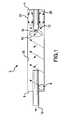
- FIG. 1is an internal view of the device.
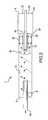
- FIG. 2is an internal view of the device as a muffler with a particle collector and an air flow opening through the bullet or projection.
- FIG. 3is an internal view of the device as a muffler with a particle collector and an air flow opening through the bullet or projection.
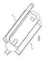
- FIG. 4is a segmental external view of the device as a muffler.
- FIG. 5is an internal view of another muffler embodiment.
- FIG. 6is another embodiment of the outlet featuring a deflector for the inlet.
- FIG. 7is a gas flow diagram.
- FIG. 8is another embodiment of the device featuring a recovery outlet to recycle unused fuel.
- FIG. 9is another embodiment of the device featuring a recovery outlet to recycle unused fuel.
- FIG. 1is an internal view of the device 2 .
- the device 2when the device 2 is attached to a vehicle exhaust system it allows the exhaust gas to flow in through the inlet 8 at the distal end 6 .
- the gasflows into the device 2 and immediately begins to spin in a vortex flowing along the inside wall 16 until it reaches the projection or bullet 12 .
- the gas flowing in the vortexcomes into contact with the projection 12 it creates a reverse venturi effect altering the course of the vortex in an upward manner directing the flow of the lighter gas toward the outlet 10 and out of the device 2 .
- a low pressure area 18develops just off the end of the projection 12 .
- the gasis directed outward toward the inside wall 16 creating a torroidal vortex 42 forcing the gas to accelerate into the inside wall 16 .
- the lighter particlesmove into the vortex that is expelling the gas and the heavier particles fall.
- This areais called the circulation loop 20 .
- the particleshere move up along the bullet where they are sent against the wall again. The particles will remain in this loop until they are small enough to move out. When the particles become small enough, i.e. light enough, to leave the circulation loop 20 they pass through the low pressure zone 18 and become captured in the vortex that removes the particles from the device 2 .
- the particlesare reduced within the circulation loop 20 by being repeatedly driven into the inside walls 16 of the device 2 . These repeated collisions have the ability to, over time, reduce particle size and then release them through the low pressure area 18 and into the vortex for expelling of the gas through the outlet 10 .
- FIG. 2is an internal view of the device as a muffler with a particle collector 22 and an air flow opening 14 through the bullet or projection 12 .
- the device 2is attached to a vehicle exhaust allowing the exhaust gas to flow in through the inlet 8 at the distal end 6 .
- the gasflows into the device 2 and immediately begins to spin in a vortex flowing along the inside wall 16 until it reaches the projection or bullet 12 .
- the gas flowing into the device 2comes into contact with the projection 12 it creates a reverse venturi effect altering the course of the vortex in an upward manner directing the flow of the lighter gas toward the outlet 10 and out of the device 2 .
- a low pressure area 18develops just off the end of the projection 12 .
- the gasis directed outward creating a torroidal vortex 42 forcing the gas to accelerate into the inside wall 16 .
- the lighter particlesmove into the vortex that is expelling the gas and the heavier particles fall.
- This areais called the circulation loop 20 .
- the particleshere move up along the bullet where they are sent against the wall again. The particles will remain in this loop until they are small enough to move out. When the particles become small enough to leave the circulation loop 20 they pass through the low pressure zone 18 and become captured into the vortex that removes the particles from the device 2 .
- This embodimenthas an opening 14 that comes in through the near end 4 through the collector 22 and its near end 32 then continuing through the bullet 14 .
- This opening 14allows for the introduction of various materials into the low pressure zone 18 and into the vortex of the device 2 .
- a material that is introduced into the devicewould be cool air to reduce the heat that develops from the engine exhaust.
- the collector 22serves the purpose of collecting particles that are large and remain in the circulation loop 20 . These particles will eventually drop out into the collector 22 through openings 28 in the distal end 30 of the collector 22 .
- the collector 22is removable and acts as a filter.
- the collector 22is baffled to create a resonating affect or is simply used as a resonator 24 . It show also be noted that without the openings 28 the particles will remain in the circulation loop 20 until they have been reduced enough to pass through the low pressure zone 18 into the vortex and on to the outlet 10 .
- FIG. 3is an internal view of the device 2 as a muffler with a particle collector 22 and an air flow opening 14 through the bullet or projection 12 . This view allows for a better look at the distal end 30 of the collector 22 . The openings 28 in the collector 22 allow the larger heavy particles to drop or fall through into the collector 22 .
- FIG. 4is a segmental external view of the device 2 as a muffler.
- the inlet 8 and the outlet 10both pass through the outside surface 34 . Both are located near the distal end 6 of the device 2 .
- the device 2is totally self contained with all operations internal to the device 2 .
- the end of the bullet 12 and the opening 14 through itare also visible. This view allows for a better understanding of the area around the bullet 12 . This area surrounding the bullet is where the circulation loop 20 exists. The heavier particles become trapped and entrained here. They will recirculate here until they have been reduced or fall into the collector 22 .
- FIG. 5is an internal view of another muffler embodiment.
- the device 2is surrounded by an outer housing 26 .
- This outer housingcan be for aesthetic value or incorporated as a larger resonator cavity.
- FIG. 6is another embodiment of the outlet 10 featuring a deflector 38 for the inlet 8 .
- This embodimentinduces a vortex faster within the device 2 .
- This deflectoris not necessary to create the vortex but will initiate it faster.
- the deflector 38is attached to the outlet 10 adjacent to the inlet 8 . The incoming gas will hit the deflector and immediately spin into a vortex.
- FIG. 7is a gas flow diagram.
- the exhaustcomes in and circulates down around the inside wall 16 .
- a low pressure area 18is created.
- the lighter particlesmove up the vortex and the heavier particles are forced out by the torroidal vortex 42 .
- These heavier particleshit the inside wall 16 reducing their size.
- the heavier particlesbecome entrained in the circulation loop 20 and move down along the inside wall 16 and along the bottom and then up the outside wall 46 of the bullet 12 to be reintroduced into the torroidal vortex 42 or as smaller particles they leave.
- the particles that are too largeremain in the loop 20 until they are reduced in size enough to pass through the low pressure zone 18 and out of the device 2 .
- FIG. 8is another embodiment of the device 2 featuring a recovery outlet 44 to recycle unused fuel or hydrocarbon.
- This embodimentis ideal for use as a muffler for a diesel motor because it has a recirculation loop 40 .
- the heavier particles that are within the circulation loop 20are drawn off and reintroduced into the combustion cycle to be reburnt. This will improve emissions and increase mileage.
- FIG. 9is another embodiment of the device featuring a recovery outlet 44 to recycle unused fuel.
- the recovery outletis the opening 14 in the projection 12 .
- the heavier particlesare drawn off through the opening 14 in the bullet 12 and reintroduced into the combustion cycle.
- the deviceis also capable of being used in other applications with any motor or process that creates an exhaust.
- the deviceis used in a coal fired power generation process when attached to the exhaust created by the process and the gas will flow into the inlet 8 of the distal end 6 allowing the exhaust gas to flow in through the inlet 8 at the distal end 6 .
- the gasflows into the device 2 and immediately begins to spin in a vortex flowing along the inside wall 16 until it reaches the projection or bullet 12 .
- the gas flowing into the device 2comes into contact with the projection 12 it creates a reverse venturi effect altering the course of the vortex in an upward manner directing the flow of the lighter gas toward the outlet 10 and out of the device 2 .
- a low pressure area 18develops just off the end of the projection 12 .
- the gasis directed outward creating a torridal vortex forcing the gas to accelerate into the inside wall 16 .
- the lighter particlesmove into the vortex that is expelling the gas and the heavier particles fall.
- This areais called the circulation loop 20 .
- the particleshere move up along the bullet where they are sent against the wall again. The particles will remain in this loop until they are small-enough to move out.
- the device 2is also adapted to be used in the incineration process. When the device is attached to the exhaust of an incinerator the exhaust will flow in through the inlet 8 at the distal end 6 . The gas flows into the device 2 and immediately begins to spin in a vortex flowing along the inside wall 16 until it reaches the projection or bullet 12 .
- the particleshere move up along the bullet where they are sent against the wall again.
- the particleswill remain in this loop until they are small enough to move out.
- the particlesbecome small enough to leave the circulation loop 20 they pass through the low pressure zone 18 and become captured into the vortex that removes the particles from the device 2 .
- the exhaustis therefore cleaned as heavier particles are either reduced or removed in the manner explained previously. That is to say collected, reduced or recirculated reducing or eliminating emissions. This is especially crucial in the incineration of hazardous waste.
- the inlet pipeenters through a first opening from the side of the cylindrical housing and near the live end.
- the outlet pipeexits from a centered opening in the live end of the cylindrical housing.
- the bullet shaped projectionis centered and attached to the inside surface of the dead end.
- the vortexis created by the ratio of the length of the inlet pipe from the inside side wall surface to the length of the outlet pipe from the inside live end surface is about 1:3 and wherein the ratio of the length of the bullet shaped projection from the inside surface of the dead end inside surface to the overall length of the enclosed cylindrical housing is about 1:3.
Landscapes
- Engineering & Computer Science (AREA)
- Mechanical Engineering (AREA)
- General Engineering & Computer Science (AREA)
- Chemical & Material Sciences (AREA)
- Combustion & Propulsion (AREA)
- Chemical Kinetics & Catalysis (AREA)
- Processes For Solid Components From Exhaust (AREA)
- Exhaust Silencers (AREA)
- Separating Particles In Gases By Inertia (AREA)
- Cyclones (AREA)
- Exhaust Gas After Treatment (AREA)
- Combined Means For Separation Of Solids (AREA)
- Chimneys And Flues (AREA)
- Physical Or Chemical Processes And Apparatus (AREA)
- Separation Of Gases By Adsorption (AREA)
- Filtering Of Dispersed Particles In Gases (AREA)
Abstract
Description
Claims (20)
Priority Applications (13)
| Application Number | Priority Date | Filing Date | Title |
|---|---|---|---|
| US12/802,273US8246704B2 (en) | 2010-06-03 | 2010-06-03 | Contained vorticies device |
| TW100119185ATWI447297B (en) | 2010-06-03 | 2011-06-01 | Contained vortices device |
| KR1020127034326AKR20130126454A (en) | 2010-06-03 | 2011-06-03 | Contained vortices device |
| MX2012013965AMX2012013965A (en) | 2010-06-03 | 2011-06-03 | Contained vortices device. |
| CN201180034561.8ACN103026016B (en) | 2010-06-03 | 2011-06-03 | Inclusion vortex device |
| RU2012151951/06ARU2012151951A (en) | 2010-06-03 | 2011-06-03 | CLOSED VORTEX DEVICE |
| EP11790114.0AEP2577008A2 (en) | 2010-06-03 | 2011-06-03 | Contained vorticies device |
| CA2801425ACA2801425A1 (en) | 2010-06-03 | 2011-06-03 | Contained vorticies device |
| BR112012030433ABR112012030433A2 (en) | 2010-06-03 | 2011-06-03 | contained vortex device and method for silencing a combustion engine mechanism of a vehicle with a muffler |
| PCT/US2011/001012WO2011152880A2 (en) | 2010-06-03 | 2011-06-03 | Contained vorticies device |
| JP2013513155AJP2013532251A (en) | 2010-06-03 | 2011-06-03 | Closed eddy current device |
| US13/527,974US8409315B2 (en) | 2010-06-03 | 2012-06-20 | Muffler |
| JP2014187357AJP5979513B2 (en) | 2010-06-03 | 2014-09-16 | Muffler for combustion engine |
Applications Claiming Priority (1)
| Application Number | Priority Date | Filing Date | Title |
|---|---|---|---|
| US12/802,273US8246704B2 (en) | 2010-06-03 | 2010-06-03 | Contained vorticies device |
Related Child Applications (1)
| Application Number | Title | Priority Date | Filing Date |
|---|---|---|---|
| US13/527,974ContinuationUS8409315B2 (en) | 2010-06-03 | 2012-06-20 | Muffler |
Publications (2)
| Publication Number | Publication Date |
|---|---|
| US20110296808A1 US20110296808A1 (en) | 2011-12-08 |
| US8246704B2true US8246704B2 (en) | 2012-08-21 |
Family
ID=45063357
Family Applications (2)
| Application Number | Title | Priority Date | Filing Date |
|---|---|---|---|
| US12/802,273Expired - Fee RelatedUS8246704B2 (en) | 2010-06-03 | 2010-06-03 | Contained vorticies device |
| US13/527,974Expired - Fee RelatedUS8409315B2 (en) | 2010-06-03 | 2012-06-20 | Muffler |
Family Applications After (1)
| Application Number | Title | Priority Date | Filing Date |
|---|---|---|---|
| US13/527,974Expired - Fee RelatedUS8409315B2 (en) | 2010-06-03 | 2012-06-20 | Muffler |
Country Status (11)
| Country | Link |
|---|---|
| US (2) | US8246704B2 (en) |
| EP (1) | EP2577008A2 (en) |
| JP (2) | JP2013532251A (en) |
| KR (1) | KR20130126454A (en) |
| CN (1) | CN103026016B (en) |
| BR (1) | BR112012030433A2 (en) |
| CA (1) | CA2801425A1 (en) |
| MX (1) | MX2012013965A (en) |
| RU (1) | RU2012151951A (en) |
| TW (1) | TWI447297B (en) |
| WO (1) | WO2011152880A2 (en) |
Cited By (1)
| Publication number | Priority date | Publication date | Assignee | Title |
|---|---|---|---|---|
| US9803667B2 (en) | 2014-05-15 | 2017-10-31 | Vtx Technology Llc | Vortex flow apparatus |
Families Citing this family (3)
| Publication number | Priority date | Publication date | Assignee | Title |
|---|---|---|---|---|
| JP6116323B2 (en) | 2013-03-29 | 2017-04-19 | 株式会社堀場製作所 | Exhaust gas mixer and constant volume sampling device |
| WO2016186907A1 (en)* | 2015-05-15 | 2016-11-24 | Vtx Technology Llc | Vortex flow apparatus |
| JP6925415B2 (en)* | 2016-09-23 | 2021-08-25 | サムスン・ヘヴィー・インダストリーズ・カンパニー・リミテッド | Silencer and maintenance method of the silencer |
Citations (15)
| Publication number | Priority date | Publication date | Assignee | Title |
|---|---|---|---|---|
| US2790554A (en)* | 1955-01-18 | 1957-04-30 | Borg Warner | Separating device |
| US3219420A (en)* | 1961-08-11 | 1965-11-23 | Alexander F Dielenberg | Fluidised bed reactors |
| US4220219A (en) | 1978-09-14 | 1980-09-02 | Flugger Ray T | Lightweight muffler and method for muffling noise |
| US4350510A (en)* | 1979-12-12 | 1982-09-21 | Hirachi, Ltd. | Centrifugal separator |
| KR20000060178A (en) | 1999-03-12 | 2000-10-16 | 정몽규 | Muffler for internal combustion engine |
| KR20020006867A (en) | 2000-07-13 | 2002-01-26 | 구자홍 | Muffler of airconditioner |
| US6385967B1 (en) | 2000-05-31 | 2002-05-14 | Shun-Lai Chen | Exhaust pipe for motor vehicle muffler |
| US20030121722A1 (en) | 2002-01-02 | 2003-07-03 | Advanced Car Specialties Limited | Exhaust gas muffler |
| US6810557B2 (en)* | 2002-01-28 | 2004-11-02 | Bissell Homecare, Inc. | Cyclone separator with vacillating debris inhibitor |
| US20070266683A1 (en)* | 2004-09-01 | 2007-11-22 | Bissell Homecare, Inc. | Cyclone separator with fine particle separation member |
| US7380639B2 (en) | 2004-10-12 | 2008-06-03 | Arlasky Performance Inc. | Backpressure reducing exhaust system with stationary blade structure |
| US7490467B2 (en) | 2004-06-15 | 2009-02-17 | Cummings Craig D | Gas flow enhancer for combustion engines |
| US7594941B2 (en) | 2006-08-23 | 2009-09-29 | University Of New Brunswick | Rotary gas cyclone separator |
| US7708789B2 (en)* | 2003-10-22 | 2010-05-04 | Bissell Homecare, Inc. | Vacuum cleaner with cyclonic dirt separation and bottom discharge dirt cup with filter |
| US8025123B2 (en) | 2006-01-17 | 2011-09-27 | Toyota Jidosha Kabushiki Kaisha | Muffler structure for vehicle |
Family Cites Families (26)
| Publication number | Priority date | Publication date | Assignee | Title |
|---|---|---|---|---|
| DE2220535C2 (en)* | 1972-04-26 | 1974-03-07 | Siemens Ag, 1000 Berlin U. 8000 Muenchen | Rotary flow vortex for the sifting of fine-grained particles |
| JPS50110160A (en)* | 1974-02-07 | 1975-08-29 | ||
| JPS5321340A (en)* | 1976-08-10 | 1978-02-27 | Nissan Motor Co Ltd | Exhaust muffler having fine particle collector |
| US4333754A (en) | 1979-06-27 | 1982-06-08 | Vortec Corporation | Anti-icing noise-suppressing vortex tube assembly |
| GB2084904A (en)* | 1980-10-08 | 1982-04-21 | Gen Electric | Electrostatically augmented cyclone separation process and apparatus |
| JPS63144853U (en)* | 1987-03-17 | 1988-09-22 | ||
| JPH0533628A (en) | 1991-07-26 | 1993-02-09 | Toyota Motor Corp | Exhaust silencer |
| JPH05332121A (en)* | 1992-05-29 | 1993-12-14 | Mitsubishi Heavy Ind Ltd | Exhaust muffler |
| JP4300593B2 (en)* | 1997-08-07 | 2009-07-22 | 株式会社日立製作所 | Cyclone system |
| JP2002295230A (en)* | 2001-03-30 | 2002-10-09 | Sanei Kogyo Kk | Simple cleaner for diesel engine exhaust gas |
| US6889499B2 (en) | 2001-05-16 | 2005-05-10 | Darryl C. Bassani | Internal combustion engine exhaust system |
| KR100437117B1 (en)* | 2002-05-16 | 2004-06-23 | 삼성광주전자 주식회사 | Cyclone-type dust collect apparatus for vacuum cleaner |
| KR20040063595A (en)* | 2003-01-08 | 2004-07-14 | 한라공조주식회사 | A muffler of compressor |
| US7383919B2 (en) | 2003-07-17 | 2008-06-10 | Arlasky Performance Inc. | Rotatable propeller driven engine exhaust system |
| JP2006077609A (en) | 2004-09-07 | 2006-03-23 | Kanto Auto Works Ltd | Muffler structure of automobile |
| KR100592096B1 (en)* | 2004-10-08 | 2006-06-22 | 삼성광주전자 주식회사 | Cyclone dust collector |
| US20060260869A1 (en) | 2005-05-18 | 2006-11-23 | Kim Jay S | Muffler having fluid swirling vanes |
| WO2007006086A1 (en) | 2005-07-08 | 2007-01-18 | Thomas Shirra | Method of and apparatus for exhausting internal combustion engines |
| US7331422B2 (en) | 2005-07-18 | 2008-02-19 | Alan Wall | Vortex muffler |
| KR100648959B1 (en)* | 2005-10-12 | 2006-11-27 | 삼성광주전자 주식회사 | Multi Cyclone Separator |
| JP2008134023A (en) | 2006-11-29 | 2008-06-12 | Daikin Ind Ltd | Muffler for refrigerant circuit |
| US8747496B2 (en)* | 2007-05-01 | 2014-06-10 | Westport Power Inc. | Compact fuel processor |
| EP2031078A1 (en)* | 2007-08-29 | 2009-03-04 | Paul Wurth S.A. | Dust catcher for blast furnace gas |
| JP2009185791A (en)* | 2008-02-08 | 2009-08-20 | Toyota Motor Corp | Exhaust gas recirculation device for internal combustion engine |
| JP2011080612A (en) | 2009-10-02 | 2011-04-21 | Fujitsu Ltd | Muffling device |
| US8104572B2 (en) | 2010-01-22 | 2012-01-31 | Butler Boyd L | Spin muffler |
- 2010
- 2010-06-03USUS12/802,273patent/US8246704B2/ennot_activeExpired - Fee Related
- 2011
- 2011-06-01TWTW100119185Apatent/TWI447297B/ennot_activeIP Right Cessation
- 2011-06-03BRBR112012030433Apatent/BR112012030433A2/ennot_activeIP Right Cessation
- 2011-06-03RURU2012151951/06Apatent/RU2012151951A/ennot_activeApplication Discontinuation
- 2011-06-03MXMX2012013965Apatent/MX2012013965A/enactiveIP Right Grant
- 2011-06-03EPEP11790114.0Apatent/EP2577008A2/ennot_activeWithdrawn
- 2011-06-03CACA2801425Apatent/CA2801425A1/ennot_activeAbandoned
- 2011-06-03KRKR1020127034326Apatent/KR20130126454A/ennot_activeCeased
- 2011-06-03WOPCT/US2011/001012patent/WO2011152880A2/enactiveApplication Filing
- 2011-06-03CNCN201180034561.8Apatent/CN103026016B/ennot_activeExpired - Fee Related
- 2011-06-03JPJP2013513155Apatent/JP2013532251A/enactivePending
- 2012
- 2012-06-20USUS13/527,974patent/US8409315B2/ennot_activeExpired - Fee Related
- 2014
- 2014-09-16JPJP2014187357Apatent/JP5979513B2/ennot_activeExpired - Fee Related
Patent Citations (16)
| Publication number | Priority date | Publication date | Assignee | Title |
|---|---|---|---|---|
| US2790554A (en)* | 1955-01-18 | 1957-04-30 | Borg Warner | Separating device |
| US3219420A (en)* | 1961-08-11 | 1965-11-23 | Alexander F Dielenberg | Fluidised bed reactors |
| US4220219A (en) | 1978-09-14 | 1980-09-02 | Flugger Ray T | Lightweight muffler and method for muffling noise |
| US4350510A (en)* | 1979-12-12 | 1982-09-21 | Hirachi, Ltd. | Centrifugal separator |
| KR20000060178A (en) | 1999-03-12 | 2000-10-16 | 정몽규 | Muffler for internal combustion engine |
| US6385967B1 (en) | 2000-05-31 | 2002-05-14 | Shun-Lai Chen | Exhaust pipe for motor vehicle muffler |
| KR20020006867A (en) | 2000-07-13 | 2002-01-26 | 구자홍 | Muffler of airconditioner |
| US20030121722A1 (en) | 2002-01-02 | 2003-07-03 | Advanced Car Specialties Limited | Exhaust gas muffler |
| US6810557B2 (en)* | 2002-01-28 | 2004-11-02 | Bissell Homecare, Inc. | Cyclone separator with vacillating debris inhibitor |
| US7708789B2 (en)* | 2003-10-22 | 2010-05-04 | Bissell Homecare, Inc. | Vacuum cleaner with cyclonic dirt separation and bottom discharge dirt cup with filter |
| US7490467B2 (en) | 2004-06-15 | 2009-02-17 | Cummings Craig D | Gas flow enhancer for combustion engines |
| US20070266683A1 (en)* | 2004-09-01 | 2007-11-22 | Bissell Homecare, Inc. | Cyclone separator with fine particle separation member |
| US7918909B2 (en)* | 2004-09-01 | 2011-04-05 | Bissell Homecare, Inc. | Cyclone separator with fine particle separation member |
| US7380639B2 (en) | 2004-10-12 | 2008-06-03 | Arlasky Performance Inc. | Backpressure reducing exhaust system with stationary blade structure |
| US8025123B2 (en) | 2006-01-17 | 2011-09-27 | Toyota Jidosha Kabushiki Kaisha | Muffler structure for vehicle |
| US7594941B2 (en) | 2006-08-23 | 2009-09-29 | University Of New Brunswick | Rotary gas cyclone separator |
Cited By (1)
| Publication number | Priority date | Publication date | Assignee | Title |
|---|---|---|---|---|
| US9803667B2 (en) | 2014-05-15 | 2017-10-31 | Vtx Technology Llc | Vortex flow apparatus |
Also Published As
| Publication number | Publication date |
|---|---|
| TWI447297B (en) | 2014-08-01 |
| US20120255808A1 (en) | 2012-10-11 |
| CA2801425A1 (en) | 2011-12-08 |
| WO2011152880A3 (en) | 2012-02-16 |
| US20110296808A1 (en) | 2011-12-08 |
| TW201200714A (en) | 2012-01-01 |
| BR112012030433A2 (en) | 2017-06-13 |
| JP2013532251A (en) | 2013-08-15 |
| WO2011152880A2 (en) | 2011-12-08 |
| MX2012013965A (en) | 2013-05-20 |
| JP2015025455A (en) | 2015-02-05 |
| US8409315B2 (en) | 2013-04-02 |
| JP5979513B2 (en) | 2016-08-24 |
| RU2012151951A (en) | 2014-07-20 |
| KR20130126454A (en) | 2013-11-20 |
| CN103026016B (en) | 2015-04-08 |
| EP2577008A2 (en) | 2013-04-10 |
| CN103026016A (en) | 2013-04-03 |
Similar Documents
| Publication | Publication Date | Title |
|---|---|---|
| US8246704B2 (en) | Contained vorticies device | |
| RU2135267C1 (en) | Pulse device to burn fuel (versions) and process of acoustic baking of microparticles (versions) | |
| JP5807124B2 (en) | Cleaning dust collection device, engine system, and ship | |
| US8220442B2 (en) | Vortex exhaust recovery system having improved muffler | |
| US7645432B1 (en) | Exhaust treatment system and method | |
| KR20070007254A (en) | Device for removing contaminants from crankcase emissions | |
| CA2029099C (en) | Method and apparatus for cooling, neutralizing, and removing suspended particulates from the gaseous products of combustion and for improving the efficiency of any furnace to which said apparatus is attached ("the kagi scrubber") | |
| US10137398B2 (en) | Apparatus and method for treatment of exhaust gas | |
| US3407575A (en) | Through-flow spark arrester | |
| WO2002075127A1 (en) | Apparatus and method for treating exhaust emissions | |
| JP2013532251A5 (en) | ||
| KR101665083B1 (en) | Reduction fuel and emissions reduction apparatus | |
| RU2133350C1 (en) | Internal combustion engine exhaust device | |
| JP6171194B1 (en) | Demister unit and EGR system | |
| CN206972333U (en) | A kind of gas extraction system of diesel engine | |
| KR102152987B1 (en) | Waste incineration apparatus having exhaust gas recombustor | |
| CN219691619U (en) | Wind guiding structure for reducing wind resistance and multistage cyclone spark extinguisher | |
| RU126806U1 (en) | DEVICE FOR BURNING OIL-CONTAINING WASTE | |
| JP2001248420A (en) | Device for removing micro particle exhausted from diesel engine | |
| US9612015B2 (en) | Oxy-combustor operable with supercritical fluid | |
| US20160069233A1 (en) | Engine exhaust after-treatment system and method | |
| WO2015129432A1 (en) | Mist separator, exhaust-gas treatment device, and ship | |
| RU151499U1 (en) | MOBILE DUST CATCH | |
| JPH0719025A (en) | Method and device for exhaust gas emission control | |
| KR20020092065A (en) | Exhaust System (Vehicle Silencer and Exhaust Gas Prevention Method) |
Legal Events
| Date | Code | Title | Description |
|---|---|---|---|
| AS | Assignment | Owner name:GREEN BRIDGE TECHNOLOGIES INTL., INC, MICHIGAN Free format text:ASSIGNMENT OF ASSIGNORS INTEREST;ASSIGNORS:BROCK, JOHN L.;THOMPSON, IV, ALEXANDER CAMPBELL;REEL/FRAME:024613/0110 Effective date:20100615 | |
| AS | Assignment | Owner name:INTEGRADIGM CORPORATION, INDIANA Free format text:ASSIGNMENT OF ASSIGNORS INTEREST;ASSIGNOR:GREEN BRIDGE TECHNOLOGIES INTL., INC.;REEL/FRAME:026640/0474 Effective date:20110228 | |
| STCF | Information on status: patent grant | Free format text:PATENTED CASE | |
| AS | Assignment | Owner name:FREDERICK J. WHIPP, INDIANA Free format text:ASSIGNMENT OF ASSIGNORS INTEREST;ASSIGNOR:INTEGRADIGM CORPORATION;REEL/FRAME:030704/0931 Effective date:20130626 | |
| AS | Assignment | Owner name:VTX TECHNOLOGY LLC, MICHIGAN Free format text:ASSIGNMENT OF ASSIGNORS INTEREST;ASSIGNOR:WHIPP, FREDERICK J.;REEL/FRAME:030724/0696 Effective date:20130629 | |
| FPAY | Fee payment | Year of fee payment:4 | |
| FEPP | Fee payment procedure | Free format text:MAINTENANCE FEE REMINDER MAILED (ORIGINAL EVENT CODE: REM.); ENTITY STATUS OF PATENT OWNER: SMALL ENTITY | |
| LAPS | Lapse for failure to pay maintenance fees | Free format text:PATENT EXPIRED FOR FAILURE TO PAY MAINTENANCE FEES (ORIGINAL EVENT CODE: EXP.); ENTITY STATUS OF PATENT OWNER: SMALL ENTITY | |
| STCH | Information on status: patent discontinuation | Free format text:PATENT EXPIRED DUE TO NONPAYMENT OF MAINTENANCE FEES UNDER 37 CFR 1.362 |