US8246636B2 - Suturing devices and methods for closing a patent foramen ovale - Google Patents
Suturing devices and methods for closing a patent foramen ovaleDownload PDFInfo
- Publication number
- US8246636B2 US8246636B2US12/057,304US5730408AUS8246636B2US 8246636 B2US8246636 B2US 8246636B2US 5730408 AUS5730408 AUS 5730408AUS 8246636 B2US8246636 B2US 8246636B2
- Authority
- US
- United States
- Prior art keywords
- suture
- needle
- suture clasp
- clasp arm
- suturing device
- Prior art date
- Legal status (The legal status is an assumption and is not a legal conclusion. Google has not performed a legal analysis and makes no representation as to the accuracy of the status listed.)
- Active, expires
Links
Images


Classifications
- A—HUMAN NECESSITIES
- A61—MEDICAL OR VETERINARY SCIENCE; HYGIENE
- A61B—DIAGNOSIS; SURGERY; IDENTIFICATION
- A61B17/00—Surgical instruments, devices or methods
- A61B17/0057—Implements for plugging an opening in the wall of a hollow or tubular organ, e.g. for sealing a vessel puncture or closing a cardiac septal defect
- A—HUMAN NECESSITIES
- A61—MEDICAL OR VETERINARY SCIENCE; HYGIENE
- A61B—DIAGNOSIS; SURGERY; IDENTIFICATION
- A61B17/00—Surgical instruments, devices or methods
- A61B17/04—Surgical instruments, devices or methods for suturing wounds; Holders or packages for needles or suture materials
- A61B17/0469—Suturing instruments for use in minimally invasive surgery, e.g. endoscopic surgery
- A—HUMAN NECESSITIES
- A61—MEDICAL OR VETERINARY SCIENCE; HYGIENE
- A61B—DIAGNOSIS; SURGERY; IDENTIFICATION
- A61B17/00—Surgical instruments, devices or methods
- A61B17/04—Surgical instruments, devices or methods for suturing wounds; Holders or packages for needles or suture materials
- A61B17/0482—Needle or suture guides
- A—HUMAN NECESSITIES
- A61—MEDICAL OR VETERINARY SCIENCE; HYGIENE
- A61B—DIAGNOSIS; SURGERY; IDENTIFICATION
- A61B17/00—Surgical instruments, devices or methods
- A61B17/00234—Surgical instruments, devices or methods for minimally invasive surgery
- A61B2017/00238—Type of minimally invasive operation
- A61B2017/00243—Type of minimally invasive operation cardiac
- A—HUMAN NECESSITIES
- A61—MEDICAL OR VETERINARY SCIENCE; HYGIENE
- A61B—DIAGNOSIS; SURGERY; IDENTIFICATION
- A61B17/00—Surgical instruments, devices or methods
- A61B17/0057—Implements for plugging an opening in the wall of a hollow or tubular organ, e.g. for sealing a vessel puncture or closing a cardiac septal defect
- A61B2017/00575—Implements for plugging an opening in the wall of a hollow or tubular organ, e.g. for sealing a vessel puncture or closing a cardiac septal defect for closure at remote site, e.g. closing atrial septum defects
- A61B2017/00623—Introducing or retrieving devices therefor
- A—HUMAN NECESSITIES
- A61—MEDICAL OR VETERINARY SCIENCE; HYGIENE
- A61B—DIAGNOSIS; SURGERY; IDENTIFICATION
- A61B17/00—Surgical instruments, devices or methods
- A61B17/04—Surgical instruments, devices or methods for suturing wounds; Holders or packages for needles or suture materials
- A61B17/0469—Suturing instruments for use in minimally invasive surgery, e.g. endoscopic surgery
- A61B2017/047—Suturing instruments for use in minimally invasive surgery, e.g. endoscopic surgery having at least one proximally pointing needle located at the distal end of the instrument, e.g. for suturing trocar puncture wounds starting from inside the body
- A—HUMAN NECESSITIES
- A61—MEDICAL OR VETERINARY SCIENCE; HYGIENE
- A61B—DIAGNOSIS; SURGERY; IDENTIFICATION
- A61B17/00—Surgical instruments, devices or methods
- A61B17/04—Surgical instruments, devices or methods for suturing wounds; Holders or packages for needles or suture materials
- A61B17/0469—Suturing instruments for use in minimally invasive surgery, e.g. endoscopic surgery
- A61B2017/0472—Multiple-needled, e.g. double-needled, instruments
Definitions
- Embodiments of the present inventionsrelate to suturing devices and methods. Specifically, preferred embodiments of the present inventions relate to suturing devices and methods for suturing a patent foramen ovale.
- suturesHealth practitioners frequently use sutures to close various openings such as cuts, punctures, and incisions in various places in the human body. Because of their importance and frequent use, several types of sutures and devices for their implantation and extraction have been developed. These devices include needles having various shapes and sizes as well as devices for inserting and removing staples. Generally, sutures are convenient to use and function properly to hold openings in biological tissue closed thereby aiding in blood clotting, healing, and prevention of scaring. However, there are some circumstances under which it is not feasible to use conventional sutures and suturing methods to close an opening. Some of these circumstances occur with incisions in arterial walls, or other internal bodily tissues. Here, catheter based devices and procedures have been suggested to close such openings.
- a foramen ovalewhich does not seal is defined a patent foramen ovale, or PFO.
- Embodiments of the present inventionsaddress the above problems by providing a suturing device and method for suturing biological tissue, such as, for example, an organ or blood vessel.
- the deviceis particularly well suited to suture a patent foramen ovale.
- One embodimentrelates to a suturing device comprising an elongate body and at least one arm, more preferably first and second arms.
- Each of said armshas a suture mounting portion which mounts an end portion of a suture.
- the armsare mounted on the elongate body such that said suture mounting portions are movable away from said body to a first position and towards said body to a second position.
- the suturing devicefurther comprises at least one needle, and preferably first and second needles, each of said needles having a distal end.
- Each of said needlesis mounted such that the distal end of the needle is movable from a position adjacent said elongate body to a position away from said body, and towards the suture mounting portion of one of the arms when in said first position, wherein the respective distal ends of the first and second needles engage respective end portions of said suture.
- the suturing apparatusfurther comprises an actuator which drives the needles.
- a suturing apparatuscomprises an elongate body having a proximal end and a distal end.
- a first suture clasp armis adapted to hold an end portion of a suture, the first suture clasp arm being extendable from the body from a retracted position to an extended position.
- a second suture clasp armis adapted to hold an end portion of a suture, the second suture clasp arm being extendable from the body from a retracted position to an extended position.
- a first suture catch mechanismis slidably housed in the elongate body, the first suture catch mechanism being moveable in a proximal to distal direction to engage a distal end of the first suture catch mechanism with the suture end held by the first suture clasp arm when the first suture clasp arm is in the extended position.
- a second suture catch mechanismis slidably housed in the elongate body, the second suture catch mechanism being moveable in a distal to proximal direction to engage a distal end of the first suture catch mechanism with the suture end held by the second suture clasp arm when the second suture clasp arm is in the extended position.
- a suturing apparatus for suturing a patent foramen ovalecomprises an elongate body having a proximal end and a distal end configured to be delivered percutaneously into the patent foramen ovale. At least a first suture clasp arm is adapted to hold a first suture end portion. The first suture clasp arm is extendable from said body from a retracted position to an extended position and configured to be placed around one of the septum primum and septum secundum of the patent foramen ovale. At least a first suture catch mechanism is slidably housed in said elongate body.
- the first suture catch mechanismis movable through one of the septum primum and septum secundum of the patent foramen ovale to engage a distal end of the first suture catch mechanism with the first suture end portion held by the first suture clasp arm when the first suture clasp arm is in the extended position.
- a system for suturing a patent foramen ovalecomprises a first suturing apparatus and a second suturing apparatus.
- the first suturing apparatuscomprises a first elongate body having a proximal end and a distal end, a first suture clasp arm adapted to hold a first suture end portion, and a first suture catch mechanism slidably housed in said elongate body.
- the first suture clasp armis extendable from said body from a retracted position to an extended position and configured to be placed around the septum primum of the patent foramen ovale.
- the first suture catch mechanismis moveable in a proximal to distal direction through the septum primum of the patent foramen ovale to engage a distal end of the first suture catch mechanism with the first suture end portion held by the first suture clasp arm when the first suture clasp arm is in the extended position.
- the second suturing apparatuscomprises a second elongate body having a proximal end and a distal end, a second suture clasp arm adapted to hold a second suture end portion, and a second suture catch mechanism slidably housed in said elongate body.
- the second suture clasp armis extendable from said body from a retracted position to an extended position and configured to be placed around the septum secundum of the patent foramen ovale.
- the second suture catch mechanismis moveable in a distal-to-proximal direction through the septum secundum of the patent foramen ovale to engage a distal end of the second suture catch mechanism with the second suture end portion held by the second suture clasp arm when the second suture clasp arm is in the extended position.
- a suturing apparatus for suturing a patent foramen ovalecomprises an elongate body having a proximal end and a distal end, a first suture clasp arm, a second suture clasp arm, a first suture catch mechanism, and a second suture catch mechanism.
- the first suture clasp armis adapted to hold a first suture end portion.
- the first suture clasp armis extendable from said body from a retracted position to an extended position and configured to be placed around the septum primum of the patent foramen ovale.
- the second suture clasp armis adapted to hold a second suture end portion.
- the second suture clasp armis extendable from said body from a retracted position to an extended position and configured to be placed around the septum secundum of the patent foramen ovale.
- the first suture catch mechanismis slidably housed in said elongate body.
- the first suture catch mechanismis moveable in a proximal-to-distal direction through the septum primum of the patent foramen ovale to engage a distal end of the first suture catch mechanism with the first suture end portion held by the first suture clasp arm when the first suture clasp arm is in the extended position.
- the second suture catch mechanismis slidably housed in said elongate body.
- the second suture catch mechanismis moveable in a distal-to-proximal direction through the septum secundum of the patent foramen ovale to engage a distal end of the first suture catch mechanism with the second suture end portion held by the second suture clasp arm when the second suture clasp arm is in the extended position.
- a method of closing a patent foramen ovale having a septum primum and a septum secundumis provided.
- An elongate bodyis advanced into a tunnel of a patent foramen ovale.
- a first suture clasp armis extended from the elongate body from a retracted position to an extended position, the first suture clasp arm holding an end portion of a suture.
- the first suture clasp armis positioned around one of the septum primum and the septum secundum.
- a first needle positioned in the elongate bodyis advanced outwardly from the body through tissue of one of the septum primum and septum secundum and into engagement with the suture end held in the first suture clasp arm.
- the first needleis retracted into the elongate body with the suture end carried by the first needle.
- a second suture clasp armis extended from the elongate body from a retracted position to an extended position, the second suture clasp arm holding an end portion of a suture.
- the second suture clasp armis positioned around the other of the septum primum and the septum secundum.
- a second needle positioned in the elongate bodyis advanced outwardly from the body through tissue of the other of the septum primum and septum secundum and into engagement with the suture end held in the second suture clasp arm.
- the second needleis retracted into the elongate body with the suture end carried by the second needle.
- the elongate bodyis withdrawn from the tunnel of the patent foramen ovale.
- the septum primum and the septum secundumare drawn closed.
- a method of closing a patent foramen ovale having a septum primum and a septum secundumis provided.
- a first suture clasp armis positioned around one of the septum primum and the septum secundum.
- the first suture clasp armholds a first suture end portion.
- a first needleis advanced through tissue of one of the septum primum and septum secundum and into engagement with the first suture end portion held in the first suture clasp arm.
- the first needleis retracted through tissue of one of the septum primum and septum secundum with the first suture end portion carried by the first needle.
- a second suture clasp armis positioned around the other of the septum primum and the septum secundum.
- the second suture clasp armholds a second suture end portion.
- a second needleis advanced through tissue of the other of the septum primum and septum secundum and into engagement with the second suture end portion held in the second suture clasp arm.
- the second needleis retracted through tissue of the other of the septum primum and septum secundum with the second suture end portion.
- the septum primum and the septum secundumare drawn closed.
- a method of closing a patent foramen ovale having a septum primum and a septum secundumis provided.
- a first elongate bodyis advanced into a tunnel of a patent foramen ovale.
- a first suture clasp armis extended from the first elongate body from a retracted position to an extended position.
- the first suture clasp armholds a first suture end portion.
- the first suture clasp armis positioned around one of the septum primum and the septum secundum.
- a first needle positioned in the elongate bodyis advanced outwardly from the body through tissue of one of the septum primum and septum secundum and into engagement with the first suture end portion held in the first suture clasp arm.
- the first needleis retracted into the first elongate body with the first suture end portion carried by the first needle.
- the first elongate bodyis withdrawn from the tunnel of the patent foramen ovale.
- a second elongate bodyis advanced near the tunnel of a patent foramen ovale.
- a second suture clasp armis extended from the second elongate body from a retracted position to an extended position.
- the second suture clasp armholds a second suture end portion.
- the second suture clasp armis positioned around the other of the septum primum and the septum secundum.
- a second needle positioned in the second elongate bodyis advanced outwardly from the body through tissue of the other of the septum primum and septum secundum and into engagement with the second suture end portion held in the second suture clasp arm.
- the second needleis retracted into the second elongate body with the second suture end portion carried by the second needle.
- the second elongate bodyis withdrawn from the tunnel of the patent foramen ovale.
- the septum primum and the septum secundumare drawn closed.
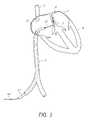
- FIG. 1illustrates a method of providing access to an exemplifying use environment, such as a patent foramen ovale.
- FIG. 2Aillustrates a side view of one embodiment of a suturing device.
- FIG. 2Billustrates a side view of the distal end of the suturing device of FIG. 2A .
- FIG. 2Cillustrates a cross-sectional view of the elongate tubular member of an embodiment of the suturing device taken along the line 2 C- 2 C of FIG. 2B .
- FIG. 2Dillustrates a cross-sectional view of the spreader assembly of an embodiment of the suturing device taken along the line 2 D- 2 D of FIG. 2B .
- FIG. 2Eillustrates a cross-sectional view of the distal tip of an embodiment of the suturing device taken along the line 2 E- 2 E of FIG. 2B .
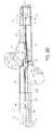
- FIG. 3illustrates a side view of an embodiment of the suturing device with the suture clasp arms deployed.
- FIG. 4Aillustrates a perspective view of the suture clasp arms.
- FIG. 4Billustrates a top plan view of an embodiment of a suture clasp arm having one suture clasp.
- FIG. 4Cillustrates a top plan view of an alternative embodiment of a suture clasp arm having two suture clasps.
- FIG. 5is a side view of an embodiment of the suturing device showing suture portions positioned in the suture clasp arms.
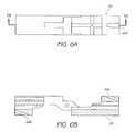
- FIG. 6Aillustrates a top plan view of an embodiment of a spreader assembly showing a needle guide.
- FIG. 6Billustrates a cross-sectional view of an embodiment of a spreader assembly showing proximal and distal needle guides.
- FIG. 7Ais a side view of an embodiment of a suture catch mechanism for engaging the proximal suture clasp arm.
- FIG. 7Bis a side view of an embodiment of a suture catch mechanism for engaging the distal suture clasp arm.
- FIG. 8Ais a side view of an embodiment of the suturing device illustrating the proximal and distal suture catch mechanisms in a stored position.
- FIG. 8Bis a side view of an embodiment of the suturing device illustrating the proximal suture catch mechanism in a deployed position.
- FIG. 8Cis a side view of an embodiment of the suturing device illustrating the distal suture catch mechanism in a deployed position.
- FIG. 9Ais a perspective view of one embodiment of a handle of the suturing device.
- FIG. 9Bis a perspective view of the handle of FIG. 9A , with a portion of the housing removed.
- FIG. 10Ais a schematic representation an embodiment of the suturing device deployed in a PFO.
- FIG. 10Bis a schematic representation as in FIG. 10A with the proximal suture clasp arm positioned around the septum primum.
- FIG. 10Cis a schematic representation as in FIG. 10B showing the proximal needle engaging the proximal suture clasp arm.
- FIG. 10Dis a schematic representation as in FIG. 10C showing the proximal needle and suture portion retracted through the septum primum.
- FIG. 10Eis a schematic representation as in FIG. 10D with the distal suture clasp arm positioned around the septum secundum.
- FIG. 10Fis a schematic representation as in FIG. 10E showing the distal needle engaging the distal suture clasp arm.
- FIG. 10Gis a schematic representation as in FIG. 10F following retraction of the distal needle and suture portion through the septum secundum.
- FIG. 10His a schematic representation as in FIG. 10G showing the suture portions positioned through the septum secundum and septum primum, and the suturing device being withdrawn.
- FIG. 10Iis a schematic representation as in FIG. 10H showing the suture portions positioned through the septum secundum and septum primum following withdrawal of the suturing device.
- FIG. 10Jis a schematic representation of an alternative embodiment showing the suture portions positioned through the septum secundum and septum primum following withdrawal of the suturing device.
- FIG. 10Kis a schematic representation of an alternative embodiment showing the suture portions positioned through the septum secundum and septum primum following withdrawal of the suturing device.
- FIG. 10Lis a schematic representation of a patch being delivered to the PFO.
- FIG. 11Ais a schematic representation of an alternative embodiment showing a suturing device with the distal clasp arm positioned around the septum secundum.
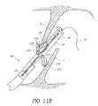
- FIG. 11Bis a schematic representation showing the suturing device of FIG. 11A with the distal needle engaging the distal suture clasp arm.
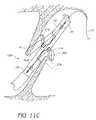
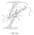
- FIG. 11Cis a schematic representation showing the suturing device of FIG. 11A with the proximal clasp arm positioned around the septum primum.
- FIG. 11Dis a schematic representation showing the suturing device of FIG. 11A with the proximal needle engaging the proximal suture clasp arm.
- FIG. 11Eis a schematic representation showing the suture portions deployed following the steps of FIGS. 11A-11D .
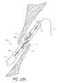
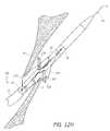
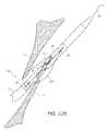
- FIG. 12Ais a schematic representation of an alternative embodiment of a suturing device being delivered through a tunnel of the PFO.
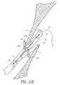
- FIG. 12Bis a schematic representation of the suturing device of FIG. 12A showing a distal suture clasp arm engaging the septum secundum.
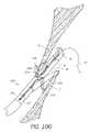
- FIG. 12Cis a schematic representation of the suturing device of FIG. 12A showing the distal needle engaging the distal suture clasp arm.
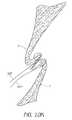
- FIG. 12Dis a schematic representation of the suturing device of FIG. 12A showing the distal needle retracted from the septum secundum.
- FIG. 12Eis a schematic representation of the suturing device of FIG. 12A showing the suturing device partially withdrawn from the tunnel of the PFO and the suture clasp arms retracted into the device.
- FIG. 12Fis a schematic representation of the suturing device of FIG. 12A showing the suturing device advanced further into the left atrium with the proximal and distal suture clasp arms extended from the suturing device.
- FIG. 12Gis a schematic representation of the suturing device of FIG. 12A showing a proximal suture clasp arm engaging the septum primum.
- FIG. 12His a schematic representation of the suturing device of FIG. 12A showing the proximal needle engaging the proximal suture clasp arm.
- FIG. 12Iis a schematic representation of the suturing device of FIG. 12A showing the proximal needle retracted from the septum primum.
- FIG. 12Jis a schematic representation of the suturing device of FIG. 12A showing the suturing device advanced further into the left atrium.
- FIG. 12Kis a schematic representation of the suturing device of FIG. 12A showing the suture clasp arms retracted into the suturing device.
- FIG. 12Lis a schematic representation of the suturing device of FIG. 12A showing the suturing device being withdrawn from the PFO.
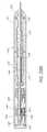
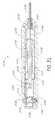
- FIG. 13illustrates a side view of one embodiment of a suturing device.
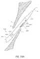
- FIG. 14Aillustrates a side view of the distal end of the suturing device of FIG. 13 .
- FIG. 14Billustrates a side view of a distal end of a suturing device of one embodiment.
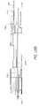
- FIG. 15Aillustrates a cross-sectional view of the elongate tubular member of an embodiment of the suturing device of FIGS. 13 and 14A , taken along the line 15 A- 15 A of FIG. 14A .
- FIG. 15Billustrates a cross-sectional view of the elongate tubular member of an embodiment of the suturing device of FIG. 14B , taken along the line 15 B- 15 B of FIG. 14B .
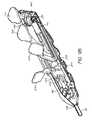
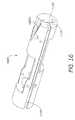
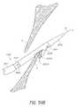
- FIG. 16illustrates a perspective view of a spreader assembly of an embodiment of the suturing device.
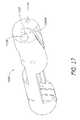
- FIG. 17illustrates another perspective view of the spreader assembly of FIG. 16 .
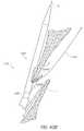
- FIG. 18Aillustrates a cross-sectional view of a distal end of an elongate tubular member, the spreader assembly of FIGS. 16 and 17 , and a housing taken along the line 18 - 18 of FIG. 15A .
- FIG. 18Billustrates a cross-sectional view of a distal end of an elongate tubular member, a spreader assembly, and a housing showing features for limiting the range of travel of suture catch mechanisms.
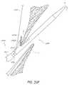
- FIG. 19illustrates a side view of an embodiment of the suturing device with the suture clasp arms deployed and various internal features shown in phantom.
- FIG. 20illustrates a perspective view of a suture clasp arm.
- FIG. 21illustrates a perspective view of a suture clasp arm.
- FIG. 22illustrates a cross-sectional view of a suture clasp arm and a needle.
- FIG. 23illustrates a perspective view of the suture clasp arm and the needle of FIG. 22 .
- FIG. 24illustrates a perspective view of a housing of an embodiment of the suturing device.
- FIG. 25illustrates another perspective view of the housing of FIG. 24 .
- FIG. 26illustrates a top view of a distal end of an embodiment of a suturing device with various features shown in phantom lines.
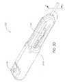
- FIG. 27is a perspective view of one embodiment of a handle of the suturing device.
- FIG. 28Ais a cross-sectional view of the handle of FIG. 27 taken along the line 28 A- 28 A shown in FIG. 27 .
- FIG. 28Bis a cross-sectional view of the handle of FIG. 27 taken along the line 28 B- 28 B shown in FIG. 27 .
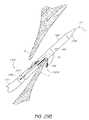
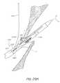
- FIG. 29Ais a schematic representation an embodiment of the suturing device deployed in a PFO.
- FIG. 29Bis a schematic representation as in FIG. 29A with a distal suture clasp arm positioned around the septum primum.
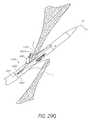
- FIG. 29Cis a schematic representation as in FIG. 29B showing the proximal needle engaging the distal suture clasp arm.
- FIG. 29Dis a schematic representation as in FIG. 29C showing the proximal needle and suture portion retracted through the septum primum.
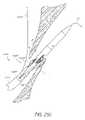
- FIG. 29Eis a schematic representation as in FIG. 29D showing the suturing device positioned to permit a proximal suture clasp arm to extend from the suturing device.
- FIG. 29Fis a schematic representation as in FIG. 29E with the proximal suture clasp arm positioned around the septum secundum.
- FIG. 29Gis a schematic representation as in FIG. 29F showing the distal needle engaging the proximal suture clasp arm.
- FIG. 29His a schematic representation as in FIG. 29G following retraction of the distal needle and suture portion through the septum secundum.
- FIG. 29Iis a schematic representation as in FIG. 29H showing the suture portions positioned through the septum secundum and septum primum, and the suturing device being withdrawn.
- FIG. 29Jis a schematic representation as in FIG. 29D showing the suturing device of FIGS. 14B and 15B positioned to permit the proximal suture clasp arm to extend from the suturing device and a second guide wire extended.
- FIG. 29Kis a schematic representation as in FIG. 29J with the proximal suture clasp arm positioned around the septum secundum.
- FIG. 29Lis a schematic representation as in FIG. 29K showing the distal needle engaging the proximal suture clasp arm.
- FIG. 29Mis a schematic representation as in FIG. 29L following retraction of the distal needle and suture portion through the septum secundum.
- FIG. 30is a perspective view of one embodiment of a handle of a knot placement device.
- FIG. 31is a cross-sectional view of the handle of FIG. 30 taken along the line 31 - 31 shown in FIG. 27 .
- FIG. 32is a cross-sectional view of a distal end of a knot placement device.
- FIG. 33is a perspective view of one embodiment of a handle of a suturing device.
- FIG. 34Ais a cross-sectional view of the handle of FIG. 33 taken along the line 34 A- 34 A shown in FIG. 33 .
- FIG. 34Bis a cross-sectional view of the handle of FIG. 33 taken along the line 34 B- 34 B shown in FIG. 33 .
- FIG. 35is a side view of an actuator and a follower of the handle of FIG. 33 .
- FIG. 36is a side view of one embodiment of a system of suturing devices.
- FIG. 37is a perspective view of a distal end of a first suturing device of the system of FIG. 36 .
- FIG. 38is a perspective view of a distal end of a second suturing device of the system of FIG. 36 .
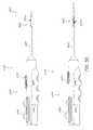
- FIG. 39Ais a schematic representation an embodiment of the first suturing device of the FIG. 37 deployed in a PFO.
- FIG. 39Bis a schematic representation as in FIG. 39A with a suture clasp arm positioned around the septum primum.
- FIG. 39Cis a schematic representation as in FIG. 39B showing a needle engaging the suture clasp arm.
- FIG. 39Dis a schematic representation as in FIG. 39C showing the needle and suture portion retracted through the septum primum.
- FIG. 39Eis a schematic representation as in FIG. 39D showing the second suturing device of FIG. 38 positioned to permit a suture clasp arm to extend from the second suturing device and a second guidewire extended.
- FIG. 39Fis a schematic representation as in FIG. 39E with the suture clasp arm positioned around the septum secundum.
- FIG. 39Gis a schematic representation as in FIG. 39F showing a needle engaging the suture clasp arm.
- FIG. 39His a schematic representation as in FIG. 39G following retraction of the needle and suture portion through the septum secundum.
- FIG. 39Iis a schematic representation as in FIG. 39H showing the suture portions positioned through the septum secundum and septum primum, and the second suturing device being withdrawn.
- FIG. 39Jis a schematic representation as in FIG. 39I showing the suture portions being joined by a first knot following withdrawal of the suturing device.
- FIG. 39Kis a schematic representation as in FIG. 39J showing the first knot being positioned between the septum secundum and septum primum.
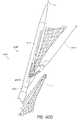
- FIG. 40Ais a schematic representation as in FIG. 39D showing the second suturing device positioned to permit the suture clasp arm to extend from the second suturing device and the second guide wire extended through the PFO.
- FIG. 40Bis a schematic representation as in FIG. 40A with the suture clasp arm positioned in the PFO around the septum secundum.
- FIG. 40Cis a schematic representation as in FIG. 40B showing the needle engaging the suture clasp arm.
- FIG. 40Dis a schematic representation as in FIG. 40C following retraction of the needle and suture portion through the septum secundum.
- FIG. 40Eis a schematic representation as in FIG. 40D showing the suture portions positioned through the septum secundum and septum primum, and the second suturing device being withdrawn.
- Embodiments of the present inventionprovide suturing devices and methods for closing an opening in biological tissue, a body lumen, hollow organ or other body cavity.
- the suturing devices and their methods useare useful in a variety of procedures, such as treating (closing) wounds and naturally or surgically created apertures or passageways.
- the suturing devicesmay be used to seal an opening in the heart wall such as an atrial septal defect, a patent ductus arteriosis or a patent foramen ovale.
- the suturing devicesmay be used to close or reduce a variety of other tissue openings, lumens, hollow organs or natural or surgically created passageways in the body.
- the suturing devicesmay be used to suture prosthetics, synthetic materials, or implantable devices in the body.
- the devicesmay be used to suture pledget within the body.
- FIG. 1illustrates one embodiment in an exemplifying use environment for closing a patent foramen ovale (PFO).
- PFOpatent foramen ovale
- Adaption of the devices and methods disclosed herein for closing a PFOmay also be made with respect to procedures for closing other bodily tissue openings, lumens, hollow organs or natural or surgically created passageways and procedures for suturing prosthetics, synthetic materials, or implantable devices in the body.
- a guidewire 10is advanced into the right atrium 2 of the heart 9 through the inferior vena cava 3 .
- the heartmay be accessed through any of a variety of pathways, such as through the inferior vena cava 3 via a femoral access site, through the superior vena cava 5 via the subclavian or jugular veins, or any other venous or arterial access sites.
- the guidewire 10can then be further positioned in the tunnel or opening of the patent foramen 8 ovale between the septum primum 7 and septum secundum 6 . With the guidewire 10 in place, the physician can insert a sheath 11 to the right atrium.
- This sheath 11is typically a single lumen catheter with a valve on its proximal end. The valve is used to prevent extraneous bleed back or to introduce medication into the patient's body.
- the sheath 11can be placed at or near the tunnel of a patent foramen ovale 8 .
- the suturing device 100described further below, can then be advanced to the PFO 8 through the lumen of the sheath 11 .
- the suturing device 100can be advanced over the guidewire 10 and positioned in the opening of the patent foramen ovale 8 without the need to insert an introducer 11 .
- Other methods of accessing the PFO or other bodily locationscan be used to insert an introducer 11 .
- FIG. 2Ashows one embodiment of the suturing device 100 for suturing an opening in a vessel wall and other biological tissue. While the device will be described in reference to suturing an opening in the heart wall such as a patent foramen ovale (PFO), the device could be used to close other openings in the heart wall, such as a patent ductus arteriosus (PDA) or an atrial septal defect (ASD), other puncture wounds in bodily tissue, or the like, or to perform other procedures as described above.
- the suturing device 100comprises an elongated tubular member 20 having a spreader assembly 30 (shown in FIG. 2B ) connected to the distal end of the elongated tubular member 20 for positioning in the opening of the PFO.
- a spreader assembly 30shown in FIG. 2B
- a handle 200is provided at the proximal end of the tubular member 20 .
- the axial length and flexibility of the elongated tubular member 20is sufficient to percutaneously access the patient's vasculature and advance the elongate tubular member 20 through the venous system to the patient's heart with the proximal end of the device remaining outside the patient's body.
- the length of the devicemay vary depending upon the intended access point and pathway to the heart.
- the axial length of the elongate tubular member 20can be between about 70-120 cm, alternatively between about 80-100 cm, alternatively about 90 cm.
- the elongate tubular member 20has a plurality of lumens extending along the axial length.
- the multi-lumen elongate tubular member 20can be manufactured in accordance with any of a variety of techniques known to those skilled in the art.
- the elongate tubular member 20can be formed from a multi-lumen extruded plastic tubing, such as a polyester, polyethelyne, polymide, nylon or any other suitable material known to those skilled in the art.
- the elongate tubular member 20comprises four central lumens 21 , 22 , 23 and 24 vertically stacked along a central axis of the elongate tubular member 20 .
- the central lumensmay be surrounded by two semicircular or D-shaped lumens 25 and 26 extending axially on opposite sides of the elongate tubular member 20 .
- the central lumens 21 , 22 , 23 , and 24will be used to provide access through the elongate tubular member 20 for a guidewire, to provide access for an actuating rod connected to the suture clasp arms, and to house one or more suture catch mechanisms or needles.
- the semi-circular shaped lumens 25 and 26can be used to deliver one or more sutures to the distal end of the elongate tubular member 20 .
- the spreader assembly 30is bonded, or otherwise joined, to the distal end of the elongated tubular member 20 , for example with epoxy or any other suitable technique known to those skilled in the art.
- the spreader assemblymay be integral with the elongate tubular member 20
- the spreader assemblycomprises central lumens 131 , 132 , 133 and 134 vertically stacked along a central longitudinal axis of the spreader assembly 30 .
- the central lumens 21 , 22 , 23 and 24 of the elongate tubular member 20 and the central lumens 131 , 132 , 133 and 134 of the spreader assembly 30are preferably substantially aligned to provide continuous passageways through the elongate tubular member 20 and spreader assembly 30 .
- a metal casing, or bullet, 40having a length greater than the length of the spreader 30 and an inner diameter substantially the same as the outer diameter of the spreader assembly 30 and elongate tubular member 20 is placed over the connection between the elongate tubular member 20 and the spreader assembly 30 to maintain the proper alignment of the internal lumens of the elongate tubular member 20 and spreader assembly 30 .
- the bulletcomprises openings 41 A and 41 B located on the opposite sidewalls of the bullet 40 for allowing the release and deployment of suture clasp arms housed within the spreader assembly 30 . Accordingly, the openings 41 A and 41 B are sized and shaped to permit the suture clasp arms to fully extend from the spreader assembly 30 .
- the bullet 40has a length such that when the proximal end of the bullet is positioned over the connection between the spreader assembly 30 and the elongate tubular member 20 , its distal end extends beyond the distal end of the spreader assembly 30 .
- a distal tip 70which may be rounded or atraumatic can be bonded or adhered to the distal end of the spreader assembly 30 , for example with epoxy or any other suitable technique known to those skilled in the art. As shown in FIG.
- the distal tipcan have at least one central lumen 172 that is axially aligned with a central lumen 132 of the spreader 30 and a central lumen 22 of elongate tubular member 20 for providing a continuous passageway through the entire length of suturing device 100 , for example for a guidewire.
- the distal tip 70may have one or more additional lumens 173 that can be aligned with lumens in the spreader assembly 30 and elongate tubular member 20 to provide additional continuous passageways, for example for housing a suture catch mechanism.
- the outer diameter of the distal tipis substantially the same size as the inner diameter of the bullet 40 such that when the distal end of the bullet 40 is positioned over the connection between the distal tip 70 and the spreader assembly 30 , the bullet maintains the proper alignment of the internal lumens of the distal tip 70 and spreader assembly 30 .
- a pair of suture clasp arms 31 A and Bare housed in recesses 41 A and 41 B in the central portion of the spreader assembly 30 .
- the suture clasp arms 31 A and 31 Bare situated parallel to the longitudinal axis of the suturing device such that the outer walls of the suture clasp arms do not extend beyond the outer diameter of the spreader assembly 30 .
- the arms 31 A and Bcan be deployed to the position shown in FIG. 3 .
- the suture clasp arms 31 A and Bare connected to an actuating rod 35 which extends through the passageway formed by lumen 134 in the spreader assembly and central lumen 24 in the elongate tubular member 20 .
- the proximal suture clasp arm 31 A and the distal suture clasp arm 31 Bmay be manufactured as a single component, or alternately fixedly connected at a central connection point.
- the distal end of the actuating arm 35may be connected to the distal suture clasp arm 31 B, offset from the middle, or central connection point, of the suture clasp arms such that proximal retraction of the actuating arm 35 will pull on the distal suture clasp arm 31 B creating a counterclockwise torquing force on the suture clasp arms which will cause both suture clasp arms 31 A and B to flip out from the spreader assembly 30 .
- the suture clasp arms 31 A and Bextend from the suturing device 100 in opposite directions along the longitudinal axis of the device.
- the arms 31 A and 31 Bform an acute angle with the longitudinal axis of the spreader.
- a first arm 31 Aextends outward toward the proximal end of the spreader assembly 30 at an angle of between about 35-55°, alternatively about 40-50°, alternatively about 45° with respect to the longitudinal axis of the spreader assembly 30
- the second arm 31 Bextends outward toward the distal end of the spreader assembly 30 at the same angle as the first arm 31 A with respect to the longitudinal axis of the spreader assembly 30 .
- the suture clasp arms 31 A and 31 Bmay be deployed simultaneously to extend equally in opposite directions with respect to the suturing device.
- the suture clasp arms 31 A and Bcan be independently actuated to be individually deployed depending upon the location of the tissue portion to be sutured.
- the second suture clasp arm 31 Bcan still be deployed at the first location to provide mechanical support and stabilization for positioning the first suture clasp arm 31 A proximal to the first tissue portion.
- the suturing device 100when closing a PFO, the suturing device 100 is first positioned such that suture clasp arm 31 A extends around the septum primum 7 such that suture portion 52 A may be engaged and pulled though the septum primum 7 to draw it toward the septum secundum 6 .
- the non-engaged suture clasp arm 31 Bis still extended toward and contacts the septum secundum 6 which pushes the suturing device 100 toward the septum primum 7 thereby assisting in placement of the suture clasp arm 31 A around the septum primum 7 and stabilizing the suturing device 100 during deployment of the suture catch mechanism to engage the suture.
- each of the suture clasp arms 31 A, 31 Bhas a suture clasp 33 for receiving and holding a suture 50 .
- the suture clasp 33can be a circular opening with a diameter sized to securely receive and hold a loop of suture 50 .
- the suturecan comprise a length of suture 50 having a loop formed at each end of the suture.
- Other details regarding the apparatuses and methods of suturing devices that may be utilized with the embodiments disclosed throughout this specificationare also found in U.S. Pat. No. 6,562,052 and are hereby incorporated by reference.
- the diameter of the suture loops and the inner diameter of the suture clasp 33are preferably substantially the same such that the suture loops can be securely positioned in the suture clasp 33 during deployment of the suture clasp arms.
- the suture clasp 33is advantageously angled such that when the suture clasp arm is deployed at an angle, the suture clasp 33 will hold the suture loop perpendicular to the path of the suture catch mechanism.
- the suture clasp arm 31can have a tab or slot 34 located on the distal end of the suture clasp arm 31 for guiding the suture loop into the suture catch 33 at the proper angle.
- the suture 50can be housed in one of the outer D-shaped, or suture, lumens 25 , 26 of the elongate tubular member 20 .
- the suture lumen 26has a port or opening 42 on the distal end of the elongate tubular member 20 .
- the suture 50can be advanced through the opening 42 such that the suture ends, or end portions 52 A and 52 B, extend outside of the suturing device 100 .
- One of the suture end portions 52 Amay extend from the opening 42 to the suture clasp arm 31 A.
- the other suture end portion 52 Bmay extend along the length of the bullet and into a side opening 71 in the distal tip 70 .
- the suture portion 52 Bmay extend out of a distal opening 73 in the distal tip, and then loop back into the opening 73 .
- the suture end portion 52 Bthen extends through side opening 71 to the suture clasp arm 31 B.
- the suture endsare positioned in the suture clasps 33 A and 33 B of the suture clasp arms 31 A and 31 B and held securely there until they are engaged and removed by a suture catch mechanism.
- the suture clasp arms 31 A and 31 Bcomprise slots 34 A and 34 B to guide the suture into the suture clasps 33 at the proper angle and assist in maintaining the suture loops in the suture clasp until they are engaged by the suture catch mechanisms.
- the suture catch mechanismengages the loops of the suture ends, the suture loops will slide out of the suture clasp 33 and be released by the suture clasp arm 31 .
- the suture clasp arms 31 A and 31 Bmay further comprise additional suture clasp(s) for holding additional suture portions.
- each suture clasp armcan be configured to deploy two sutures from the suturing device to a particular location for suturing a single tissue portion.
- each suture clasp arm 431has two suture clasps 433 A and 433 B for receiving two different suture portions 150 and 151 .
- each suture clasp armcan further include two slots 434 A and 434 B for guiding the suture portions 150 and 151 into the suture clasps 433 A and 433 B.
- the spreader assembly 30includes a plurality of needle guides 60 A and 60 B for guiding a plurality of suture catch mechanisms, such as a needle or other penetrating mechanism, towards the deployed suture clasp(s).
- the spreader assembly 30may comprise two needle guides 60 A and 60 B located on the distal and proximal ends of the spreader assembly for guiding two needles toward proximally and distally deployed suture arms 31 A and 31 B depicted in FIG. 3 .
- Each of the needle guides 60 A and 60 Bcomprises an angled groove or channel in the sidewall of the spreader assembly 30 such that it will deflect a suture catch mechanism, or needle, exiting the suture assembly 30 along a path that intercepts the suture clasps 33 A and 33 B of the suture clasp arms when the suture clasp arms 31 A and 31 B are in a deployed position.
- the suture arms 31 A and 31 Bmay be sized such that a groove having an angle of between about 10-35°, alternatively about 15-25°, alternatively about 19° with respect to the longitudinal axis of the spreader assembly will spread the needles to the proper angle to engage the suture loops in the deployed suture clasps 33 .
- the proximal needle guide 60 Ais aligned with lumen 131 of the spreader assembly and lumen 21 of the elongate tubular member such that when a suture catch mechanism is advanced through the passageway formed by lumens 131 and 21 , the distal end of the needle will be deflected by the needle guide 60 A towards the deployed suture clasp arm 31 A.
- distal needle guide 60 Bis aligned with lumen 173 of the distal tip such that when the distal tip of a needle housed in lumen 173 is extended towards suture clasp arm 31 B, the needle will be deflected toward the suture clasp 33 .
- the suture catch mechanism 161which is configured for engaging the suture clasp arm 31 A extending toward the proximal end of the spreader assembly 30 comprises an elongate, straight needle 161 .
- the needle 161has a sharp, distal tip 163 for penetrating a tissue portion positioned between the suturing device and the deployed suture clasp arm 31 A and a notch or groove 162 on the distal tip 162 for engaging the loop of suture portion 52 A held by suture clasp 33 .
- the notch or groove 162is shaped or angled upward in order to grasp and dislodge the loop from the suture clasp 33 and retain the suture portion 52 A against the groove 162 as the needle is pulled back through the suture clasp 33 and tissue portion and retracted back into the suturing device 100 .
- suture catch mechanism 165which is configured to engage a suture clasp arm 31 B extending towards the distal end of the spreader assembly 30 comprises an elongate needle 165 having a distal portion 166 bent approximately 180 degrees such that a portion of the needle is turned back upon itself.
- the turned portion 166 of the needle 165has a length sufficient to extend from the spreader assembly 30 and engage the suture clasp 33 B on suture clasp arm 31 B when suture clasp arm 31 B is in a fully deployed position.
- the turned back portion 166has a sharp distal tip 167 for penetrating a tissue portion positioned between the suturing device and the deployed suture clasp arm 31 B and a notch or groove 168 on the distal tip 167 for engaging a loop of suture help by suture clasp arm 31 B.
- the notch or groove 168 on the needleis configured to grasp and retain the loop of suture portion 52 B from the suture catch 33 B as the turned portion 166 of the needle 165 ( FIG. 8B ) is conveyed through the tissue portion and retracted back into the groove 173 ( FIGS. 8B and 8C ) of the distal tip 70 of the suturing device 10 .
- the needles 161 and 165are flexible and are preferably made of a material with shape memory, such as nickel titanium or NITINOL. Alternatively, the needles 161 and 165 may be comprised of spring steel, surgical stainless steel or any variation thereof.
- the needles 161 and 165can be housed within a central passageway formed by lumens within the elongate tubular member, spreader assembly and distal tip.
- suture catch mechanism 161is slidably housed in the passageway formed by the central lumens 21 of the elongate tubular member 20 and central lumen 131 of the spreader assembly while suture catch mechanism 165 is slidably housed in the passageway formed by central lumen 23 of the elongate tubular member, central lumen 133 of the spreader assembly and lumen 173 of the distal tip 70 .
- the proximal end of the needle guide 60 Ais aligned with a lumen 131 (see FIG. 2B ) extending though the spreader assembly 30 such that when needle 161 , or other suture catch mechanism, is advanced through the passageway formed by central lumen 21 in the elongate tubular member 20 and central lumen 131 in the spreader assembly 30 , the distal end of the needle will exit the suturing device through central lumen 131 and be advanced along the groove of the needle guide 60 A.
- the needle guide 60 Athen deflects the distal end of needle 161 outward along the angle of the groove to penetrate suture clasp 33 A on the suture clasp arm 31 A and engage the suture portion 52 A held by the suture clasp 33 A. Once the needle 161 has engaged the suture portion 52 A, the needle 161 may be retracted back into central lumen 131 along with the suture portion 52 A held by groove 162 on the distal end of needle 161 . (See FIG. 8C .)
- the distal end of needle guide 60 Bis aligned with a lumen 173 in the distal tip of the suturing device.
- the needle 165has been advanced through central lumen 123 in the elongate tubular member beyond the spreader assembly 30 and positioned a slot or cavity 173 within the distal tip 70 of the suturing device that has been aligned with the central lumen 123 of the elongate tubular member.
- the cavity 173has a diameter sized to receive the distal end of the needle 165 , including the turned portion 166 .
- the turned portion 166is positioned in cavity 173 such that the distal tip 167 is aligned with the needle guide 60 B located on the distal end of the spreader assembly 30 .
- the turned portion 166 of the needlewill be advanced along the groove of the needle guide 60 B and deflected outward along the angle path of the groove to penetrate the deployed suture clasp 33 B on the suture clasp arm 31 B and engage suture portion 52 B held therein.
- the proximal end of the needle 165may then be pushed forward through the central lumen 123 of the elongate tubular member which will cause the bent portion 166 of the needle to be retracted along needle guide 60 B into cavity 173 along with the suture portion 52 B held by the groove 168 on the distal end of the needle 165 .
- the suture catch assemblycan comprise two suture catch mechanisms, or needles housed on opposite sides of the elongate tubular member 20 for engaging the two suture clasp arms.
- the needlesmay be independently actuated such that the needles may be independently deployed.
- the suture catch assemblymay comprise four needles, for example two needles housed on each side of the elongate tubular member for engaging multiple suture portions in each of the suture clasp arms.
- each of the needlesmay be independently actuated or alternatively both needles for engaging a single suture clasp arm may be jointly actuated such that they are deployed at the same time.
- the handle 200includes a housing 201 which is attached to the proximal end of the elongate tubular member 20 .
- the housing 201has an aperture 202 providing a passageway between the handle 200 and the multiple lumens of the elongate tubular member 20 .
- One or more levers or buttons 210 , 216 , 240 and 250may extend from the housing 201 .
- the levers or buttons 210 , 216 , 240 and 250can be connected to actuating rods or mechanisms for deploying and/or retracting the suture clasp arms and suture catch mechanisms moveably housed in the suturing device.
- the handle 200can have two actuating levers 210 and 216 for deploying and retracting the suture catch mechanisms such as needles 161 and 165 of the suturing device.
- the proximal end of needle 165extends from the proximal end of central lumen 23 in the elongate tubular member through opening 202 into the handle 200 and is inserted into an opening 211 in a lever needle holder 212 .
- the needle 165may be securely connected to opening 211 in the lever needle holder 212 by friction fit in the opening 211 , by bonding with epoxy, or any other suitable technique know to those in the art.
- the lever needle holder 212is permanently connected to a needle deployment lever 210 extending from the handle housing 201 , such that in use, when the physician pushes the lever forward or pulls the lever back, the needle deployment lever 210 will advance or retract the needle holder 212 longitudinally along an axis of the handle 200 and thus advance or retract the attached needle 163 longitudinally within the lumen 23 of the elongate tubular member 20 .
- the housing 200comprises a fixed length opening 213 surrounding the needle lever 210 which provides a limit to the distance the needle 163 can be advanced or retracted by limiting the distance over which the lever 210 can be pushed or pulled.
- the axial length of the opening 213should be sufficient to permit the turned distal end of the needle 163 to be extended from a pre-deployment position within the suturing device 100 to engage the distal suture clasp arm 31 A in a fully deployed position, as discussed above.
- limiting the distance the needle can be deployedmay advantageously prevent the needle from being advanced too far and potentially puncturing adjacent tissue.
- the proximal end of needle 161is likewise configured to extend through central lumen 21 of the elongate tubular member 20 and is inserted into an opening 214 in a lever needle holder 215 .
- the lever needle holder 215is permanently connected to a second needle deployment lever 216 extending from the handle housing 201 , such that in use, when the physician pushes the lever forward or pulls the lever 216 back, the needle deployment lever 216 will advance or retract the needle holder 215 and thus advance or retract the attached needle 161 .
- the housing 201comprises a fixed length opening 217 surrounding the needle lever 216 which provides a limit to the distance the needle 161 can be advanced or retracted by limiting the distance over which the lever 216 can be pushed or pulled.
- the axial length of the opening 217should be sufficient to permit the distal end of the needle 161 to be extended from a pre-deployment position within the elongate tubular member 20 to engage the proximal suture clasp arm 31 A in a fully deployed position, as discussed above.
- Deployment of the suture claps arms 31 A and 31 Bcan be performed by depressing a button 240 located on the handle 200 .
- the button 240may be connected to an arm puller mechanism 241 which is configured to be extended and retracted along a longitudinal axis of the handle 200 , which is operably connected to actuating rod 35 .
- the arm puller mechanismmay have a slot configured to receive the proximal end of the actuating rod 35 .
- the actuating rod 35extends through central lumen 24 of the elongate tubular member 20 and is connected to the suture clasp arms 31 such that proximal retraction of the actuating rod 35 causes the suture clasp arms 31 A and B to extend from the spreader assembly 30 .
- the actuating rod 35can be connected to the distal suture clasp arm 31 B at a location that causes the suture clasp arms 31 A and 31 B to swing out from the spreader assembly 30 in a counter-clockwise direction.
- button 240when button 240 is depressed, the arm pull mechanism 241 is pulled back against spring 251 causing the actuating rod 35 to be retracted though central lumen 24 , thus deploying the suture clasp arms.
- buttons 240 and 240When button 240 has been completely depressed, the button 240 engages a lip 245 of the arm puller mechanism 241 and maintains the arm puller mechanism 241 in a locked, retracted position compressing spring 251 .
- a second button 250is located on handle 200 , proximal to button 240 .
- Button 250has a lever 252 extending within the housing 201 which is configured to engage an edge of button 240 and raise the button 240 from lip 245 of the arm puller mechanism. Once the arm puller mechanism 241 has been released, spring 251 may expand to an uncompressed state, thereby pushing the arm puller mechanism 241 forward.
- FIGS. 10A-10LThe operation of the device 100 , described above, according to one embodiment is illustrated in sequence in FIGS. 10A-10L in conjunction with a procedure for closing a patent foramen ovale (PFO) in a patient's heart.
- PFOpatent foramen ovale
- the distal end of a suturing device 100is advanced through a venous access, such as the inferior vena cava, into the patient's left atrium and positioned in the tunnel 8 of the PFO between the septum primum 7 and the septum secundum 6 .
- the suturing device 100may be advanced over a guidewire 10 or alternatively delivered through a catheter introducer sheath 11 using techniques which are known in the art.
- the suturing device 100is initially positioned with the distal tip extending beyond the tunnel of the PFO, such that the spreader assembly 30 , and thus the suture clasp deployment arms are adjacent the tip of the secundum primum 7 .
- the suture clasp arms 31 A and 31 Bmay then deployed from the spreader assembly such that the proximal suture clasp arm 31 A extends around the tip of the secundum primum 7 .
- the suture clasp arm 31 Aholds a suture portion 52 A extending from opening 42 ( FIG. 2B ) on the suturing device in suture clasp 33 A such that the suture portion is positioned on the opposite side of the secundum primum 7 relative to the suturing device 100 .
- the distal suture clasp arm 31 Bis also extended from the spreader assembly and abuts the septum secundum 6 , causing the suturing device 100 and proximal suture clasp arm 31 A to be pushed toward the septum primum, thus assisting to properly position the proximal suture clasp arm 31 A adjacent to the septum primum 7 .
- needle 161may be deployed from the suturing device 100 to penetrate the septum primum 7 and engage the suture clasp arm positioned on the opposite side of the septum primum 7 , as shown in FIG. 10C .
- the needle 161is advanced through a passageway in the suturing device and deflected by needle guide 60 A along an angle that intersects the deployed suture clasp arm 31 A as it exits the suturing device 100 .
- the needlehas a sharp distal tip which penetrates the tissue of the septum primum and engages suture clasp 33 A located on the tip of the suture clasp arm 31 A.
- the needleis initially advanced through the suture clasp 33 A which holds a suture portion 52 A. When the needle is advanced through the suture clasp 33 A, a groove on the needle tip engages the suture portion 52 A.
- the needle 161 and engaged suture portion 52 Aare then retracted through the tissue of the septum primum 7 and into the needle passageway of the suturing device 100 .
- the suture clasp arms 31 A and Bmay then be closed and the device may be repositioned such that the spreader assembly 30 and suture clasp arms 31 A and B are adjacent the tip of the septum secundum 6 .
- the suture clasp armsmay remain extended.
- the suturing deviceis withdrawn proximally through the tunnel of the PFO 8 until the suture clasp arms can be deployed such that the distal suture clasp arm 31 B extends around the tip of the septum secundum 6 .
- the suture clasp arm 31 Bholds a suture portion 52 B extending from opening 42 on the suturing device 100 in suture clasp 33 B such that the suture portion 52 b is positioned on the opposite side of the septum secundum 6 relative to the PFO 8 and the suturing device 100 .
- the proximal suture clasp arm 31 Ais also extended from the spreader assembly and abuts the septum primum 7 , causing the suturing device 100 and distal suture clasp arm 31 B to be pushed toward the septum secundum 6 , thus assisting to properly position the distal suture clasp arm 31 B around the septum secundum 6 .
- a needle 165may be deployed from the distal end of the suturing device 100 to penetrate the septum secundum 6 and engage the suture portion 52 B. As shown in FIG. 10F , the tip of the needle 165 is advanced from a location distal the suture clasp arms 31 A and 31 B through the tissue of the septum secundum 6 towards deployed suture clasp arm 31 B. As discussed above with respect to FIGS.
- the needle 165comprises a turned portion 166 , such that the turned portion 166 will be advanced toward the deployed suture arm 31 B, as shown, when the proximal portion of the needle 165 is pulled proximally through the suturing device 100 .
- the turned portion of the needle 166is advanced from the suturing device 100 , the turned portion 166 is deflected outward by a needle guide 60 B along an angle that intersects the suture clasp 33 B located on the tip of deployed suture arm 31 B.
- the needle 165has a sharp distal tip which penetrates the tissue of the septum secundum 6 and engages suture clasp 33 B located on the tip of the suture clasp arm 31 B.
- the needle 165is initially advanced through the suture clasp 33 B which holds a portion of suture 52 b .
- a groove on the needle tipengages the suture portion 52 b.
- suture portion 52 BAs shown in FIG. 10G , once the suture portion 52 B has been engaged, the needle 165 and engaged suture portion 52 B are then retracted through the tissue of the septum secundum 6 and into a cavity on the distal tip 70 of the suturing device 100 . Once the suture portion 52 B has been engaged and pulled through the tissue of the septum secundum, the suture clasp arms 31 A and B may then be closed and the suturing device may be withdrawn from the patient's heart. As shown in FIG. 10H , suture portion 52 A has been positioned through the septum primum 7 while suture portion 52 B has been positioned through the septum secundum.
- the suture portions 52 A and 52 Bwill extend proximally from the PFO tunnel 8 . These suture end portions can then be pulled tight as shown in FIG. 10I to draw the septum secundum 6 and septum primum 7 towards one another and close the PFO.
- FIG. 10Jshows an alternative configuration for the septum primum and the septum secundum after the suture end portions are pulled tight to close the PFO.
- the flap of the septum secundum 6turns or folds so that the tips of both the septum primum and septum secundum extend in the same direction.
- FIG. 10Killustrates an alternative embodiment where the flap of the septum primum turns or folds so that the tip of the septum primum extends in the opposite direction compared to the tip of the septum secundum.
- a knotmay be applied to the PFO to close the PFO.
- a device for applying a knotmay be used, such as described in U.S. Patent Publication No. 2007-0010829 A1, published Jan. 11, 2007, the entirety of which is hereby incorporated by reference.
- FIG. 10Lillustrates another embodiment in which a patch 254 may be applied and may be delivered over the suture portions 52 A and 52 B to the PFO. Further details regarding delivery of a patch, as well as other devices, structures and methods that may be incorporated with the above or below embodiments, may be found in U.S. Pat. Nos. 5,860,990, 6,117,144, and 6,562,052, the entirety of each which is hereby incorporated by reference.
- FIGS. 11A-11Eillustrate an alternative sequence for delivering suture to close a PFO.
- the extended suture clasp arm 31 Bis first positioned around the septum secundum 6 , and as shown in FIG. 11B , the needle 165 is advanced proximally through tissue of the septum secundum to engage the suture portion 52 B. The needle is withdrawn from the septum secundum 6 , carrying the suture portion 52 B with it, into the elongate body.
- the extended suture clasp arm 31 Ais then positioned around the septum primum 7 , and as shown in FIG. 11D , the needle 161 pierces the tissue of the septum primum to engage suture portion 52 A in suture clasp arm 31 A.
- the needle 161is retracted, carrying the suture portion 52 A into the elongate body.
- the suturing device 100can then be withdrawn from the PFO, and the PFO can be closed as described above.
- FIGS. 12A-12Lillustrate another embodiment of a suturing device 100 used for closing the PFO.
- the suturing device 100is similar to the suturing devices described above, except that the distal tip 70 of the suturing device may comprise an elongated distal tip that assists in navigating the device over the guidewire 10 and through the tunnel of the PFO.
- the suture portions 52 A, 52 Bmay exit the port or opening 42 , with suture portion 52 B extending to the distal suture clasp arm 31 B, and the suture portion 52 A extending into port 71 before returning proximally to the proximal suture clasp arm 31 A.
- the suturing device 100may be delivered over the guidewire 10 to the PFO as described above, and as illustrated in FIG. 12A , may be positioned with the spreader assembly 30 located proximal to the PFO tunnel 8 .
- the suture clasp arms 31 A and 31 Bmay be deployed from the spreader assembly 30 .
- the spreader assembly 30may be spaced away from the PFO prior to deployment of the suture clasp arms, to allow the arms room to deploy.
- the suturing device 100may then be advanced such that the distal suture clasp arm 31 B engages or is positioned adjacent the septum secundum 6 .
- the suture clasp arm 31 Bholds suture portion 52 B extending from opening 42 on the suturing device.
- needle 165may then be deployed from the suturing device, passing through tissue of the septum secundum into engagement with suture portion 52 B carried by the suture clasp arm 31 B. Retraction of the needle 165 , as shown in FIG. 12D , carries the suture portion 52 B through the tissue of the septum secundum 6 and into the body of the suturing device 100 .
- the suturing devicemay be partially withdrawn from the tunnel of the PFO and the suture clasp arms 31 A and 31 B may be retracted back into the suturing device, as shown in FIG. 12E . While in this low profile configuration, the suturing device can then be advanced further through the tunnel of the PFO into the left atrium, and the suture clasp arms 31 A and 31 B can be deployed once they are positioned past the tunnel of the PFO, as shown in FIG. 12F .
- FIG. 12Gshows the suturing device 100 partially retracted to cause the proximal suture clasp arm 31 A to engage or be positioned around or adjacent the septum primum 7 . As shown in FIG.
- needle 161can then be advanced from the suturing device, through tissue of the septum primum 7 , and into engagement with the suture portion 52 A carried by the suture clasp arm 31 A. Retraction of the needle 161 back into the suturing device, as shown in FIG. 12I , carries the suture portion 52 A through tissue of the septum primum 7 .
- FIG. 12Jillustrates the suturing device advanced further into the left atrium to allow the suture clasp arms 31 A and 31 B room to close before withdrawal of the device.
- the suturing device 100With the arms closed or retracted, as shown in FIG. 12K , the suturing device 100 can be withdrawn from the tunnel of the PFO, as shown in FIG. 12L .
- the PFOmay be closed using the suture portions 52 A and 52 B according to methods hereinbefore described.
- FIG. 13shows a suturing device 1100 for suturing an opening in a vessel wall or other biological tissue. While the device will be described in reference to suturing an opening in the heart wall, such as a patent foramen ovale (PFO), the device 1100 , like the device 100 , could be used to close other openings in the heart wall, such as a patent ductus arteriosus (PDA) or an atrial septal defect (ASD), other openings in bodily tissue, or the like. The device 1100 could also be used to suture adjacent biological structures or any other time it may be desired to apply a suture to a biological structure, or to perform other procedures as described above with respect to the device 100 .
- PFOpatent foramen ovale
- the device 1100could also be used to suture adjacent biological structures or any other time it may be desired to apply a suture to a biological structure, or to perform other procedures as described above with respect to the device 100 .
- the suturing device 1100comprises an elongate tubular member 1020 having a spreader assembly 1090 , shown in greater detail in FIGS. 14A and 19 , connected to the distal end of the elongate tubular member 1020 for positioning in the opening of the PFO.
- a handle 1200is provided at the proximal end of the tubular member 1020 .
- the elongate tubular member 1020can be similar to the elongate tubular member 20 in some respects.
- the elongate tubular member 1020has a plurality of lumens 1021 , 1022 , 1023 and 1024 extending along the axial length of the member 1020 in a generally stacked arrangment.
- the elongate tubular member 1020can have similar dimensions to the elongate tubular member 20 .
- the member 1020can be manufactured by similar techniques and from similar materials to the member 20 .
- the elongate tubular member 1020can differ from the elongate tubular member 20 in some respects.
- the elongate tubular member 1020may additionally comprise a one or more lumens, such as lumens 1025 , 1026 , and 1027 that are shown in FIG. 15A as extending axially within elongate tubular member 1020 on either side of the lumens 1021 , 1022 , 1023 and 1024 .
- the lumens 1021 , 1022 , 1023 , 1024 , 1025 , 1026 and 1027can be used to provide access through the elongate tubular member 1020 for a guidewire, to provide access for one or more actuating rods connected to suture clasp arms, to house one or more suture catch mechanisms or needles, and to deliver one or more sutures to the distal end of the elongate tubular member 1020 .
- Some embodimentsmay also employ these lumens, or include further lumens, for injection of die, housing an additional guidewire, or to facilitate molding of the elongate tubular member.
- an elongate tubular member 1020 ′shown in FIGS. 14B and 15B , includes lumens for injection of die and an additional guidewire.
- the elongate tubular member 1020 ′is similar to the elongate tubular member 20 in some respects.
- similar features of the elongate tubular member 1020 ′are indicated with numerals similar to those of elongate tubular member 1020 followed by a prime (′).
- elongate tubular member 1020 ′comprises a lumen 1028 ′ through which die can be injected into the treatment site, and a lumen 1029 ′ for a second guidewire 1010 .
- further lumensmay be used for other purposes, such as for injection of die to an additional location or to house yet another guidewire.
- the elongate tubular member 1020 ′can comprise one or more openings near the spreader assembly 1090 between the lumen 1028 ′ and the treatment site to permit expulsion of die from the lumen 1028 ′.
- diemay pass from the lumen 1028 ′ through a spreader assembly 1090 ′ to the treatment site.
- the second guidwire 1010can pass through the lumen 1029 ′ into the spreader assembly 1090 ′, which can have a guide, ramp or other feature to direct the second guidewire 1010 through an opening 1043 ′ and away from the spreader assembly 1090 ′.
- the elongate tubular member 1020 ′can comprise an opening proximal to and near the spreader assembly 1090 ′ between the lumen 1029 ′ and the treatment site for passage of the second guidewire 1010 .
- the spreader assembly 1090is bonded, or otherwise joined, to the distal end of the elongated tubular member 1020 , for example, with epoxy or by any other suitable technique known to those skilled in the art.
- the spreader assembly 1090can comprise a spreader 1030 ( FIG. 18 ), one or more suture clasp arms 1031 , a casing 1040 , and a distal tip 1070 .
- the spreader 1030comprises one or more lumens.
- the spreader 1030has lumens 1133 and 1136 that extend generally parallel to a longitudinal axis of the spreader assembly 1090 , as shown in FIG. 16 .
- the lumens 1022 , 1023 , and 1024 of the member 1020are preferably substantially aligned with the lumen 1133 of the spreader 1030
- the lumen 1026 of the member 1020is preferably substantially aligned with the lumen 1136 of the spreader 1030 to provide continuous passageways between the elongate tubular member 1020 and the spreader 1030 .
- a casing 1040is placed over the connection between the elongate tubular member 1020 and the spreader 1030 to facilitate proper alignment of the internal lumens of the elongate tubular member 1020 and spreader 1030 , as shown in FIG. 18A .
- the casingis preferably made of metal, but can also be made of other materials such as plastics.
- the casing 1040can comprise openings, or recesses, 1041 A and 1041 B located on the opposite sidewalls of the casing 1040 for allowing the release and deployment of a pair of suture clasp arms 1031 A and 1031 B housed within the spreader 1030 .
- the openings 1041 A and 1041 Bare sized and shaped to permit the suture clasp arms to fully extend from the spreader 1030 .
- the casing 1040has a length such that when the proximal end of the casing 1040 is positioned over the connection between the spreader 1030 and the elongate tubular member 1020 , the distal end of the casing 1040 extends beyond the distal end of the spreader 1030 and, in some embodiments, engages a distal tip 1070 and/or a housing, such as housing 1080 shown in FIGS. 18A and 19 , that is positioned between the spreader 1030 and the tip 1070 .
- the pair of suture clasp arms 1031 A and 1031 Bare housed in the recesses 1041 A and 1041 B in the spreader assembly 1090 .
- the suture clasp arms 1031 A and 1031 Bare situated substantially parallel to the longitudinal axis of the suturing device such that the outer walls of the suture clasp arms do not extend beyond the outer diameter of the spreader assembly 1090 .
- the suture clasp arms 1031 A and 1031 Bare connected to actuating rods 1035 A and 1035 B which extend through the passageways formed by lumens 1133 and 1136 in the spreader assembly and lumens 1024 and 1026 in the elongate tubular member 1020 , as shown in FIG. 15A .
- the arms 1031 A and 1031 Bcan be deployed to the position shown in FIG. 19 by movement of the actuating rods 1035 A and 1035 B relative to the spreader 1030 .
- the distal suture clasp arm 1031 A and the proximal suture clasp arm 1031 Bare manufactured as separate components.
- the distal suture clasp arm 1031 A and the proximal suture clasp arm 1031 Bare shown in greater detail in FIGS. 20 and 21 , respectively.
- Each of the arms 1031may be pivotally connected to the spreader 1030 at a first connection point, such as pivot apertures 1091 , and connected to the actuating rods 1035 at a second connection point, such as apertures 1092 .
- the armsmay be connected to the spreader 1030 and the actuating rods 1035 by pins or by other techniques, such as by integral construction employing one or more compliant hinges. Accordingly, movement of the actuating rods 1035 relative to the spreader 1030 results in movement of the arms 1031 .
- the suture clasp arms 1031 A and 1031 Bextend from the suturing device 1100 in opposite directions from the longitudinal axis of the device.
- the arms 1031 A and 1031 Bform an acute angle with the longitudinal axis of the spreader.
- a first arm 1031 Aextends outward toward the proximal end of the spreader assembly 1090 at an angle of between about 35-55°, alternatively about 40-50°, alternatively about 45° with respect to the longitudinal axis of the spreader assembly 1090 .
- the second arm 1031 Bcan extend outward toward the distal end of the spreader assembly 1090 at approximately the same angle as the first arm 1031 A with respect to the longitudinal axis of the spreader assembly 1090 .
- the second arm 1031 Bcan extend outward from the spreader assembly 1090 at angle larger or smaller than the angle of the first arm 1031 A with respect to the longitudinal axis of the spreader assembly 1090 .
- the suture clasp arms 1031 A and 1031 Bcan be independently actuated to be individually deployed depending upon the location of the tissue portion to be sutured. For example, in closing a PFO, the suturing device will first be positioned with respect to a first tissue portion to be sutured and then moved to a second position for suturing a second tissue portion. More specifically, as shown in FIG. 29B , when closing a PFO, the suturing device 1100 can be first positioned such that suture clasp arm 1031 A extends around the septum primum 7 such that suture portion 52 A may be engaged and pulled though the septum primum 7 to draw it toward the septum secundum 6 . The non-engaged suture clasp arm 1031 B can remain retracted in the spreader 1030 , as shown in FIG. 29B .
- the suture clasp arms 1031 A, 1031 Blike the suture clasp arms 31 , have suture clasps 1033 A, 1033 B (see FIG. 19 ) for receiving and holding a suture 50 .
- the suture clasps 1033 A, 1033 B of the suture clasp arms 1031 A, 1031 Bmay be configured in a manner similar to or the same as that described with respect to the suture clasps 33 .
- each clasp 1033can be a circular opening with a diameter sized to securely receive and hold a loop of suture 50 .
- the suture endsare positioned in the suture clasps 1033 A and 1033 B of the suture clasp arms 1031 A and 1031 B and held securely there until they are engaged and removed by suture catch mechanisms 1161 and 1165 .
- the suture clasp arms 1031 A and 1031 Bcan comprise slots 1034 A and 1034 B ( FIGS. 20 and 21 ) to guide the suture into the suture clasps 1033 at the proper angle and assist in maintaining the suture loops in the suture clasp until they are engaged by the suture catch mechanisms.
- the suture catch mechanismengages the loops of the suture ends, the suture loops will slide out of the suture clasp 1033 and be released by the suture clasp arm 1031 .
- the suture clasp arms 1031can comprise legs 1093 that extend away from the clasps 1033 , as illustrated in FIGS. 20 and 21 .
- the legs 1093can engage tissue portions at a location remote from a location where a suture catch mechanism is to penetrate a biological structure.
- the legs 1093can gather the tissue toward the location where the suture catch mechanism is to penetrate the biological structure to facilitate secure suturing of the biological structure.
- the suture 50can be housed in the lumen 1025 (see FIG. 15A ) of the elongate tubular member 1020 .
- the suture lumen 1025can have a port or opening 1042 near the distal end of the elongate tubular member 1020 , as shown in FIG. 19 .
- the suture 50can be advanced through the opening 1042 such that the suture ends, or end portions 52 A and 52 B, extend outside of the suturing device 1100 .
- One of the suture end portions 52 Bmay extend from the opening 1042 to the suture clasp arm 1031 B.
- the other suture end portion 52 Amay extend along the length of the casing and into a side opening 1081 in the housing 1080 (see FIGS. 19 , 24 , and 26 ).
- the suture portion 52 Amay loop back out of the opening 1081 to the suture clasp arm 1031 A.
- the housing 1080can have one or more openings that align with complementary openings in the spreader 1030 .
- the housing 1080can comprise a groove, slot or lumen 1089 extends generally parallel to a longitudinal axis of the housing 1080 , as shown in FIGS. 24 and 25 .
- the slot 1089 of the housing 1080is preferably substantially aligned with a groove, slot, or lumen 1139 (see FIGS. 16-17 ) of the spreader 1030 to provide continuous passageways between the housing 1080 and the spreader 1030 .
- the housing 1080can comprise an aperture 1085 that intersects the slot 1089 and extends distally toward a central longitudinal axis of the housing 1080 , as shown in FIG. 25 .
- the housing 1080can comprise apertures 1083 and 1088 , shown in FIG. 24 , that extend generally parallel to a longitudinal axis of the spreader assembly 1090 .
- the apertures 1083 and 1088 of the housing 1080are preferably substantially aligned with lumens 1133 and 1138 (see FIG. 17 ) of the spreader 1030 to provide continuous passageways between the housing 1080 and the spreader 1030 .
- the aperture 1088can extend generally along the longitudinal axis of the housing 1080 and may extend entirely through the housing or may, as shown in FIG. 24 , extend only partially through the housing 1080 .
- the aperture 1080can be intersected by the side opening 1081 and an opening 1082 .
- the aperture 1083can be intersected by an aperture 1084 .
- the housingcan comprise a suture retention mechanism.
- the aperture 1088can accommodate a follower pin 1094 and a spring 1095 that urges the follower pin out of the opening 1088 .
- a cross pin 1096can extend through the opening 1082 and engage the follower pin 1094 to limit the range of travel of the follower pin 1094 and inhibit rotation of the follower pin 1094 within the aperture 1088 .
- a proximal end of the follower pin 1094engages a cam leg 1097 of the arm 1031 A, shown in FIG. 20 such that when the arm 1031 A is in the retracted position (see FIG. 14A ) the cam leg 1097 pushes the follower pin 1094 into the aperture 1088 compressing the spring 1095 .
- the cam leg 1097moves away from the housing 1080 allowing the follower pin 1094 to move proximally.
- the follower pin 1094can have a hook 1098 , as illustrated in FIG. 26 .
- a portion of the suture 50 that is looped through the opening 1081extends around the hook 1098 .
- the follower pin 1094moves distally such that the hook retains the suture 50 within the opening 1081 .
- the hook 1098releases the suture 50 to permit the suture 50 to be pulled from the opening 1081 .
- the suture retention mechanismcan allow the user of the device 1100 to control the release of the suture 50 from the opening 1081 in the housing 1080 to reduce the likelihood of the suture end portion 52 A being pulled prematurely from the suture clasp 1033 A, to provide slack in the suture 50 when the suture catch mechanism retrieves the suture end portion 52 A, and to release the suture 50 to permit the suture catch mechanism pull the suture 50 through a biological structure.
- the suture catch mechanism 1161can be similar to or the same as the suture catch mechanism 161 , shown in FIG. 7A .
- the suture catch mechanism 1161can be configured for engaging the suture clasp arm 1031 A and can comprise an elongate, straight needle.
- the suture catch mechanism 1165can be similar to or the same as the suture catch mechanism 165 , shown in FIG. 7B .
- the suture catch mechanism 1165is configured to engage a suture clasp arm 1031 B and can comprise a bent needle.
- the needles 1161 and 1165can be housed within passageways formed by lumens within the elongate tubular member 1020 , spreader 1030 , and the housing 1080 .
- the suture catch mechanism 161is slidably housed in the lumen 1021 of the elongate tubular member 1020
- suture catch mechanism 165is slidably housed in the passageway formed by the lumen 1023 of the elongate tubular member, the lumen 1133 of the spreader 1030 , and lumen 1083 of the housing 1080 .
- the spreader 1030includes a plurality of needle guides 1060 A and 1060 B for guiding a plurality of suture catch mechanisms, such as a needle or other penetrating mechanism, towards the deployed suture clasp(s).
- the spreader 1030may comprise two needle guides 1060 A and 1060 B located on the distal and proximal ends of the spreader 1030 for guiding two needles toward deployed suture arms 1031 A and 1031 B illustrated in FIG. 19 .
- Each of the needle guides 1060 A and 1060 Bcomprises an angled groove or channel in the sidewall of the spreader 1030 such that it will deflect a suture catch mechanism, or needle, exiting the suture assembly 1090 along a path that intercepts the suture clasps 1033 A and 1033 B of the suture clasp arms when the suture clasp arms 1031 A and 1031 B are in a deployed position.
- the suture arms 1031 A and 1031 Bmay be similar to or the same as the suture arms 31 A and 31 B.
- the suture arms 1031 A and 1031 Bcan be sized such that a groove having an angle of between about 10-35°, alternatively about 15-25°, alternatively about 19° with respect to the longitudinal axis of the spreader assembly will spread the needles to the proper angle to engage the suture loops in the deployed suture clasps 1033 .
- the proximal needle guide 1060 A( FIGS. 16 and 18A ) is aligned with the lumen 1021 of the elongate tubular member such that when a suture catch mechanism is advanced through the lumen 1021 , the distal end of the needle will be deflected by the needle guide 1060 A towards the deployed suture clasp arm 1031 A.
- the needle 1161may be retracted back into the lumen 1021 with the suture portion 52 A held on the distal end of needle 1161 , in a manner similar to that shown in FIG. 8C .
- distal needle guide 1060 B( FIGS. 17 and 18A ) is aligned with aperture 1083 of the housing 1080 such that when the distal tip of a needle housed in aperture 1083 is extended towards the suture clasp arm 1031 B, the needle will be deflected toward the suture clasp 1033 B.
- the needle 1165similar to the needle 165 , has been advanced through the lumen 1023 in the elongate tubular member 1020 beyond the spreader 1030 and positioned a slot or cavity 1083 within the housing 1080 of the suturing device that has been aligned with the lumen 1133 of the spreader 1030 .
- the cavity 1083is sized to receive the distal end of the needle 1165 , including a turned portion similar to the turned portion 166 (see FIG. 7B ).
- the turned portionis positioned in cavity 1083 such that the distal tip is aligned with the needle guide 1060 B located on the distal end of the spreader 1030 .
- the proximal end of the needle 1165when the proximal end of the needle 1165 is pulled back through the lumen 1023 of the elongate tubular member 1020 , the turned portion of the needle will be advanced along the groove of the needle guide 1060 B and deflected outward along the angle path of the groove to penetrate the deployed suture clasp 1033 B on the suture clasp arm 1031 B and engage suture portion 52 B held therein.
- the proximal end of the needle 165may then be pushed forward through the lumen 1023 of the elongate tubular member which will cause the bent portion of the needle to be retracted along needle guide 1060 B into cavity 1083 along with the suture portion 52 B held on the needle 1165 .
- a suture catch mechanismsuch as the needle 1161 or the needle 1165
- when advancedmay be oriented in direction toward a location slightly closer to or slightly farther from a longitudinal axis of the device 1100 than the center of the suture clasp 1033 .
- a suture catch mechanism that is oriented in a direction that is toward a location slightly closer to or slightly farther from the longitudinal axis of the device 1100 than the center of the suture clasp 1033may, in some instances, not properly engage the suture. As a result, the suture catch mechanism may not successfully retract the suture end portion.
- the one or more of the suture clasp arms 1031can have a deflector, such as deflecting plates 1099 , 2099 , shown in FIGS. 20-23 .
- the deflecting plates 1099 , 2099are shown partially obscuring an opening on a back side of the suture clasp 1033 relative to the direction from which a suture catch mechanism, such as a needle 2161 , penetrates the suture clasp 2033 , as shown in FIG. 22 .
- a suture catch mechanismsuch as a needle 2161
- the needle 2161engages the deflector plate 2099 , as shown in FIG. 22 , and is diverted from its previous course toward a longitudinal axis of the device 1100 .
- the suture catch mechanismcan be diverted away from a longitudinal axis of the device.
- a suture engaging portionsuch as a hook, recess, or groove 2161 , moves toward a portion of a suture end 2052 , shown schematically in FIG. 22 .
- the dimensions of the needleincluding the size and location of the suture engaging portion and the size and shape the needle tip, the size of the suture clasp, and the distance by which the deflectors obscure the back opening of the suture clasp should be relatively proportioned such that the deflectors 1099 , 2099 cause the suture engaging portion of the needle to engage the portion of the suture end as the needle returns to its previous orientation.
- the hook 2162would engage the suture portion 2052 as it retracted from the suture clasp 2033 .
- the deflector platesmay be generally rectangular, as shown in FIG. 23 , or may have other configurations, such as generally H-shaped as shown in FIG. 21 .
- the deflector platescan be made from metal, while in other embodiments the deflector plates can be made of plastics or other materials of sufficient rigid or resiliency to deflect a suture catch mechanism.
- the deflector platesmay be joined to the suture clasp arms by welding, epoxy, adhesives or by other methods. In an alternative embodiment, the deflectors can be integrally formed with the suture clasp arm.
- the deflectorscan compensate for misalignment of a suture catch mechanism with the center of a suture clasp relative to a longitudinal axis of the device to provide consistent capture of a suture end portion by the suture catch mechanism.
- bending of the elongate tubular membercan affect the relative positions of the ends of the suture catch mechanisms to the spreader assembly. For example, if an elongate tubular member is bent then a distal end of a suture catch mechanism extending along the inside of the bend in the elongate member relative to the central axis of the elongate tubular member would be advanced relative to the spreader assembly. In such a circumstance, the suture catch mechanism may be advanced through a suture clasp farther than is desired, which may result in enlargement of a loop at an end of a suture that in turn inhibits the ability of the suture catch mechanism to retract the and of the suture.
- a distal end of a suture catch mechanism extending along the outside of the bend in the elongate member relative to the central axis of the elongate tubular memberwould be retracted relative to the spreader assembly.
- the suture catch mechanismmay not be advanced through a suture clasp far enough to engage a suture end portion held by the suture clasp.
- the effects of bending of the elongate tubular membercan be reduced or eliminated by using a suture catch mechanism that is sufficiently long to engage the corresponding suture clasp even if the suture catch mechanism extends along the outside of a bend in the elongate member relative to the central axis of the elongate member. Advancement of the suture catch mechanism may be limited by providing a stop mechanism in proximity to the spreader assembly where the effects of bending are small or absent.
- a tube 1061can be attached to the needle 1161 and another tube 1062 can be attached to the elongate tubular member 1020 within a counterbore in the lumen 1021 .
- the inner diameter of tube 1062is smaller than the outer diameter of tube 1061 such that tube 1061 cannot be advanced through tube 1062 , thereby limiting the advancement of the needle 1161 relative to the spreader 1030 .
- the tube 1061can be attached to the needle 1161 and extend over a portion of the length of the needle 1161 within the lumen 1021 .
- the tube 1061limits the movement of the suture catch mechanism by preventing movement of the suture catch mechanism along the guide 1060 A by interference of the tube 1061 with the proximal end of the spreader 1030 .
- movement of the bent needle 1165 toward the suture clasp arm 1031 Bcan be limited by attachment of a tube 1065 to the needle 1165 at a location distal to the spreader 1030 .
- the tube 1065has an outer diameter that is larger than a dimension of the lumen 1133 such that the tube 1065 cannot be moved into the spreader 1030 as the needle 1165 is moved proximally, thereby limiting the movement of the needle 1161 relative to the spreader 1030 in a proximal direction.
- the suture catch assemblymay comprise four needles, for example two needles housed on each side of the elongate tubular member for engaging multiple suture portions in each of the suture clasp arms.
- each of the needlesmay be independently actuated or alternatively both needles for engaging a single suture clasp arm may be jointly actuated such that they are deployed at the same time.
- the distal tip 1070is shown in FIGS. 14A , 19 , and 29 A as having a tapered configuration, but may alternatively be rounded or have other configurations.
- the distal tip 1070is preferably atraumatic and can be bonded, adhered, or otherwise joined to the distal end of the spreader assembly 1090 , for example, by insert molding or any other suitable technique known to those skilled in the art.
- the distal tip 1070can have at least one lumen 1072 that forms a continuous passage with the aperture 1085 and the slot 1089 of the housing 1080 ( FIG. 25 ) and the slot 1039 ( FIG. 16 ) of the spreader 1030 and lumen 1027 of the elongate tubular member 1020 ( FIG. 15A ), which may accommodate, for example, a guidewire.
- the distal tip 1070may have one or more additional lumens 1173 that can be aligned with lumens in the spreader assembly 1030 and elongate tubular member 1020 to provide additional continuous passageways, for example for housing a suture catch mechanism.
- the outer diameter of the distal tipis substantially the same size as the inner diameter of the casing 1040 such that when the distal end of the casing 1040 is positioned over the connection between the distal tip 1070 , the housing 1080 , and the spreader 1030 , the casing maintains the proper alignment of the internal lumens of the distal tip 1070 , the housing 1080 , the spreader 1030 , and the elongate member 1020 .
- the handle 1200includes a housing 1201 which is attached to the proximal end of the elongate tubular member 1020 .
- the housing 1201has an aperture 1202 providing a passageway between the handle 1200 and the multiple lumens of the elongate tubular member 1020 .
- One or more actuators 1210 , 1216 , 1240 and 1260may extend from the housing 1201 .
- the pulls or knobs 1210 , 1216 , 1240 and 1260can be connected to actuating rods or mechanisms for deploying and/or retracting the suture clasp arms and suture catch mechanisms moveably housed in the suturing device.
- the elongate member 1020is fixed to the housing 1201 in any suitable manner such as by welding, adhesion, or other bonding process to a collar 1203 .
- the cylinder 1203is engaged by the housing 1201 .
- the cylinder 1203can be rectangular or any other shape.
- the cylinder 1203is connected to the housing 1201 in a manner that prevents limits rotation of the cylinder 1203 with the member 1020 relative to the housing 1201 .
- the elongate member 1020has a plurality of cutouts (not shown) that expose the actuator rods 1035 and the suture catch mechanisms 1161 and 1165 for connection to the actuators 1210 , 1216 , 1240 , and 1260 .
- the handle 1200can have two pulls 1210 and 1216 for deploying and retracting the suture catch mechanisms such as needles 1161 and 1165 of the suturing device.
- the pulls 1210 and 1216can extend from the housing through openings 1213 and 1217 , respectively, as shown in FIG. 27 .
- the proximal end of needle 1165extends from the proximal end of the lumen 1023 in the elongate tubular member through opening 1202 into the handle 1200 and is exposed by a cutout in the elongate tubular member 1020 for connection to a shaft 1276 , shown in FIGS. 28A and 28B .
- the shaft 1276can be generally U-shaped to permit the shaft to pass over the elongate member 1020 in a direction transfers to a longitudinal axis of the member 1020 .
- the needle 1165may be connected to the shaft 1276 directly by a suitable bonding process, or indirectly, such by connection to a small tube that is adhered to the needle 1165 , for example, by epoxy, which is in turn connected to a tab 1286 .
- the tab 1286can be connected to the shaft 1276 at a notch 1296 in the shaft 1276 .
- the pull 1216can be connected to the shaft by a bonding process or by mechanical means, such as a set screw.
- the proximal end of needle 1161extends from the proximal end of the lumen 1021 in the elongate tubular member 1020 through opening 1202 into the handle 1200 and is exposed by a cutout in the elongate tubular member 1020 for connection to a shaft 1270 , shown in FIGS. 28A and 28B .
- the shaft 1270can be generally U-shaped to permit the shaft to pass over the elongate member 1020 in a direction transfers to a longitudinal axis of the member 1020 .
- the needle 1161may be connected to the shaft 1270 directly by a suitable bonding process, or indirectly, such as by connection to a small tube (not shown) that is adhered to the needle 1161 , for example, by epoxy, which is in turn connected to a tab 1280 .
- the tab 1280can be connected to the shaft 1270 at a notch 1290 in the shaft 1270 .
- the pull 1210can be connected to the shaft by a bonding process or by mechanical means, such as a set screw.
- a spring 1218can be positioned between the pulls 1210 and 1216 .
- the spring 1218can bias the needle 1161 proximally and the needle 1165 distally by biasing the pull 1210 , which is connected to the needle 1161 , from the pull 1216 , which is connected to the needle 1165 .
- a usercan advance the needle 1161 by moving the pull 1210 to compress the spring 1218 .
- the spring 1218can assist in retraction of the needle 1161 as the spring 1218 decompresses.
- a usercan draw the needle 1165 proximally by moving the pull 1216 to compress the spring 1218 . As the spring 1218 decompresses the needle 1165 is moved distally within the elongate member 1020 .
- the suture claps arms 1031 A and 1031 Bcan be deployed by rotation of actuators, or knobs, 1240 and 1260 .
- the knobs 1240 , 1260can be connected to threaded members 1242 , 1262 in a manner that prevents the knobs 1240 , 1260 from rotating with respect to the threaded members 1242 , 1262 .
- a tube 1222which can be fixedly attached to the housing 1201 , can extend through the threaded members 1242 , 1262 such that the threaded members 1242 , 1262 can both slide over and rotate with respect to the tube 1222 .
- the tube 1222can have two slots 1243 and 1263 corresponding to the threaded members 1242 , 1262 .
- the two slots 1243 and 1263are configured to allow two pins 1244 and 1264 to extend through the slots 1243 , 1263 and operatively engage the threaded members 1242 , 1262 such that rotation of the threaded members 1242 , 1262 with respect to the tube 1222 causes the pins 1244 , 1264 to move along the length of the slots 1243 , 1263 .
- the pins 1244 , 1264are connected to shafts 1245 , 1265 positioned within the tube 1222 .
- the shafts 1245 , 1265can be connected to the actuator rods 1035 A and 1035 B by tabs, 1246 , 1266 .
- the tabs 1246 , 1266can be welded or otherwise attached to the actuator rods 1035 A and 1035 B and attached by any suitable bonding process to the shafts 1245 , 1265 at notches 1247 , 1267 .
- the threaded members 1242 , 1264move the pins 1244 , 1264 along the slots 1243 , 1263 . Movement of the pins 1244 , 1264 in a direction along a longitudinal axis of the handle 1200 causes the shafts 1245 , 1265 to move the actuator rods 1035 A and 1035 B either proximally or distally depending on the direction of rotation of the knobs 1240 , 1260 . As discussed above, proximal and distal movement of the actuator rods 1035 A and 1035 B causes the suture clasp arms 1031 A and 1031 B to move between a retracted position, shown in FIG. 14A , and an extended position, shown in FIG. 19 . The knobs 1240 , 1260 can be rotated individually to independently deploy and retract the suture clasp arms 1035 A and 1035 B.
- the handle 1200can also comprise springs 1248 , 1268 that bias the threaded members 1242 , 1262 along the tube 1222 .
- the springs 1248 , 1268can bias the threaded members 1242 , 1262 either proximally or distally.
- the springs 1248 , 1268bias the threaded members 1242 , 1262 in directions that bias the suture clasp arms 1031 A, 1031 B toward in their extended positions such that rotation of the threaded member 1242 , 1246 past the fully open position of the suture clasp arms 1031 A, 1031 B results in compression of the springs 1248 , 1268 .
- the springs 1248 , 1268can bias the threaded members 1242 , 1262 in directions that bias the suture clasp arms 1031 A, 1031 B toward in their retracted positions.
- FIGS. 29A-291The operation of the device 1100 , described above, is illustrated according to one embodiment in FIGS. 29A-291 in conjunction with a procedure for closing a patent foramen ovale (PFO) in a patient's heart.
- PFOpatent foramen ovale
- the distal end of a suturing device 1100is advanced through a venous access, such as the inferior vena cava, into the patient's left atrium and positioned in the tunnel 8 of the PFO between the septum primum 7 and the septum secundum 6 .
- the suturing device 1100may be advanced over a guidewire 10 or alternatively delivered through a catheter introducer sheath 1011 using techniques which are known in the art.
- the suturing device 1100is initially positioned with the distal tip 1070 extending beyond the tunnel of the PFO, such that the spreader assembly 1090 is near the tip of the secundum primum 7 and at least the suture clasp deployment arm 1031 A is permitted to extend from the spreader assembly 1090 .
- the suture clasp arm 1031 Amay then deployed from the spreader assembly 1090 and then the device 1100 is retracted until the suture clasp arm 1031 A extends around the tip of the secundum primum 7 , as shown in FIG. 29B , and gathers the tissue of the septum primum 7 between the arm 1031 A and the spreader 1030 . Referring to FIG.
- the suture clasp arm 1031 Aholds a suture portion 52 A, which may or may not still extend from opening 1081 of the housing 1080 , in the suture clasp 1033 A such that the suture portion 52 A is positioned on the opposite side of the secundum primum 7 relative to the suturing device 1100 .
- needle 1161may be deployed from the suturing device 1100 to penetrate the septum primum 7 and engage the suture clasp arm positioned on the opposite side of the septum primum 7 .
- the needle 1161is advanced through a passageway in the suturing device and deflected by needle guide 1060 A ( FIG. 18A ) along an angle that intersects the deployed suture clasp arm 1031 A as it exits the suturing device 1100 .
- the needlehas a sharp distal tip which penetrates the tissue of the septum primum 7 and engages suture clasp 1033 A located on the tip of the suture clasp arm 1031 A, as shown in FIG. 29C .
- the needleis initially advanced through the suture clasp 1033 A which holds a suture portion 52 A. When the needle is advanced through the suture clasp 1033 A, a groove or hook on the needle tip engages the suture portion 52 A.
- the needle 1161 and engaged suture portion 52 Aare then retracted through the tissue of the septum primum 7 and into the lumen 1021 of the elongate member 1020 of the suturing device 1100 .
- the device 1100may be advanced slightly so that the suture clasp arm 1031 A can be closed without pinching the septum primum 7 .
- the device 1100may then be repositioned such that the spreader assembly 1090 is adjacent the tip of the septum secundum 6 .
- the suturing device 1100is withdrawn proximally through the tunnel of the PFO 8 until the suture clasp arm 1031 B can be deployed.
- the suture clasp arm 1031 Bcan then be extended then the device 1100 can be advanced such that the suture clasp arm 1031 B extends around the tip of the septum secundum 6 , as shown in FIG. 29F , and gathers the tissue of the septum secundum 6 between the arm 1031 B and the spreader 1030 .
- the suture clasp arm 1031 Bholds a suture portion 52 B extending from opening 1042 in suture clasp 1033 B such that the suture portion 52 B is positioned on the opposite side of the septum secundum 6 relative to the PFO 8 and the suturing device 1100 .
- the needle 1165may be deployed from the distal end of the suturing device 1100 to penetrate the septum secundum 6 and engage the suture portion 52 B. As shown in FIG. 29G , the tip of the needle 1165 is pulled proximally from a location distal the suture clasp arm 1031 B through the tissue of the septum secundum 6 towards deployed suture clasp arm 1031 B.
- the needle 1165is deflected outward by a needle guide 1060 B ( FIG. 18A ) as the needle 1165 extends from the suturing device 1100 along an angle that intersects the suture clasp 1033 B located on the tip of deployed suture arm 1031 B.
- the needle 1165has a sharp distal tip which penetrates the tissue of the septum secundum 6 and engages suture clasp 1033 B located on the tip of the suture clasp arm 1031 B.
- the needle 1165is initially advanced through the suture clasp 1033 B which holds a portion of suture 52 B. When the needle 166 is advanced through the suture clasp 1033 B, a groove or hook on the needle tip engages the suture portion 52 B.
- the needle 1165 and engaged suture portion 52 Bare then retracted distally through the tissue of the septum secundum 6 and into the cavity 1083 of the suturing device 1100 .
- the suture clasp arm 1031 Bmay then be closed and the suturing device 1100 may be withdrawn from the patient's heart.
- the suture portion 52 Ahas been positioned through the septum primum 7 while suture portion 52 B has been positioned through the septum secundum.
- the suture portions 52 A and 52 Bwill extend proximally from the PFO and can then be pulled to draw the septum secundum 6 and septum primum 7 towards one another to close the PFO, as shown in FIG. 10I , 10 J, or 10 K.
- the suture 50preferably causes the septum secundum 6 and septum primum 7 to turns or folds so that the tip of the septum primum 7 extends in the opposite direction compared to the tip of the septum secundum 6 , as illustrated in FIG. 10 k.
- a knotmay be applied to the PFO to close the PFO.
- a device for applying a knotmay be used, such as described in U.S. Patent Publication No. 2007-0010829 A1, published Jan. 11, 2007, the entirety of which is hereby incorporated by reference.
- the method of securing the suture portions illustrated in FIG. 10L by applying a patch 254may be used.
- further details regarding delivery of a patchas well as other devices, structures and methods that may be incorporated with the above or below embodiments, may be found in U.S. Pat. Nos. 5,860,990, 6,117,144, and 6,562,052, the entirety of each which is hereby incorporated by reference.
- FIGS. 29J-29MThe operation of the device 1100 ′, described above and shown in FIGS. 14B and 15B , is illustrated according to one embodiment in FIGS. 29J-29M in conjunction with a procedure for closing a patent foramen ovale (PFO) in a patient's heart.
- the operation of the device 1100 ′can be similar to the operation of the device 1100 in some respects.
- the distal end of a suturing device 1100 ′is advanced through a venous access, such as the inferior vena cava, into the patient's left atrium and positioned in the tunnel 8 of the PFO between the septum primum 7 and the septum secundum 6 then operated in the manner described above with reference to FIGS. 29A-D to pass a suture portion 52 A through the septum primum 7 .
- the operation of the device 1100 ′can differ from the operation of the device 1100 in other respects.
- the device 1100 ′can be used in conjunction with the second guidewire 1010 to facilitate placement of a suture portion through the septum secundum 6 in a location at or near a center of the septum secundum 6 .
- Such placement of the suture through the septum secundum 6may improve the likelihood of successful closure of the PFO.
- bloodmay continue to flow through the PFO after placement of the suture and application of a knot to the suture.
- use of the device 1100 ′ with the second guidewire 1010can improve the likelihood of securely closing the PFO.
- the suturing device 1100 ′may be withdrawn proximally through the tunnel of the PFO 8 until the suture clasp arm 1031 B′ can be deployed, as shown in FIG. 29J .
- the second guidewire 1010can be advanced from the lumen 1029 ′ ( FIG. 15B ) through the opening 1043 ′ ( FIG. 14B ) into the superior vena cava ( FIG. 1 ).
- the second guidewire 1010may be preloaded in the device 1100 ′ before introduction of the device 1100 ′ into the body such that a distal end of the second guidewire is near the opening 1043 ′.
- the suture clasp arm 1031 B′can then be extended and the device 1100 ′ can be advanced such that the suture clasp arm 1031 B′ extends around the tip of the septum secundum 6 , as shown in FIG. 29K , and gathers the tissue of the septum secundum 6 between the arm 1031 B′ and the spreader 1030 ′.
- the suture clasp arm 1031 B′can be extended from the spreader assembly 1090 ′ before the second guidewire 1010 is advanced into the superior vena cava.
- the suturing device 1100 ′can be configured such that when the second guidewire 1010 is advanced into the superior vena cava, the second guidewire 1010 directs the device 1100 ′ toward the center of the septum segundum 6 as the device 1100 ′ is advanced.
- the suture clasp arm 1031 B′With the suturing device 1100 ′ positioned with the suture clasp arm 1031 B′ extending around the tip of the septum secundum 6 , as illustrated in FIG. 29K , the suture clasp arm 1031 B′ holds a suture portion 52 B extending from opening 1042 ′ in suture clasp 1033 B′ such that the suture portion 52 B is positioned on the opposite side of the septum secundum 6 relative to the PFO 8 and the suturing device 1100 ′.
- the needle 1165 ′may be deployed from the distal end of the suturing device 1100 ′ to penetrate the septum secundum 6 and engage the suture portion 52 B. As shown in FIG. 29L , the tip of the needle 1165 ′ is pulled proximally from a location distal the suture clasp arm 1031 B′ through the tissue of the septum secundum 6 towards deployed suture clasp arm 1031 B′ to engage the suture portion 52 B.
- the needle 1165 ′ and engaged suture portion 52 Bare then retracted distally through the tissue of the septum secundum 6 and into the cavity 1083 ′ of the suturing device 1100 ′, as illustrated in FIG. 29M .
- the suture clasp arm 1031 B′may then be closed and thereafter the second guidewire 1010 retracted into the suturing device 1100 ′.
- the second guidewire 1010can be retracted into the suturing device 1100 ′ before the suture clasp arm 1031 B′ is closed.
- the suturing device 1100 ′may be withdrawn from the patient's heart and the PFO can be closed as described above.
- FIGS. 30-32An embodiment of a device 2100 for applying a knot to a suture, comprising a handle 2110 and an elongate tubular member 2120 , is illustrated in FIGS. 30-32 , which is similar in some respects to the devices described in U.S. Patent Publication No. 2007-0010829 A1, published Jan. 11, 2007, but differs in some respects.
- the device 2100can be used to apply a knot to a suture in any of the methods described above.
- the handle 2110 of the device 2100comprises a housing 2130 , a button 2140 , and a knob 2150 .
- the housing 2130comprises an aperture 2132 configured to allow longitudinal and rotational movement of the knob 2150 , a passage 2134 for movement of the button 2140 into and out of the housing 2130 , and a mounting recess 2136 .
- the mounting recess 2136can accommodate, support, and limit them movement of a mounting hub 2160 .
- the mounting hub 2160can be fixedly attached to the elongate member 2120 .
- An actuating rod 2180can extend through the elongate member 2120 to a shaft 2152 that is connected to the knob 2150 .
- the shaft 2152can be fixedly attached to the actuating rod 2180 .
- the button 2140can comprise a pin 2142 .
- the pin 2142can extends into a recess 2135 of the passage 2134 .
- the recess 2135can be dimensioned such that rotation and translation of the pin 2142 and button 2140 within the passage 2134 is constrained such that the button 2140 is not forced out of the passage 2134 by a spring 2144 that is positioned in the passage 2134 between the button 2140 and the housing 2130 .
- the button 2140can have a hook, or projection, 2146 to engage the shaft 2152 .
- the aperture 2132 in the housing 2130is configured to allow a user to manipulate at least a portion of the knob 2150 and can extend along the longitudinal axis of the device 2100 into the passage 2134 .
- the housing 2130can have a neck or ring 2138 that slidably and rotatably supports the shaft 2152 .
- a spring 2137biases the knob 2150 distally from the neck 2138 .
- the aperture 2132can have a narrow region 2133 and a wide region 2135 .
- the narrow region 2133can be dimensioned to inhibit rotation of the shaft 2152 when a pin 2154 , which extends from the shaft 2152 , is located within the narrow region 2133 .
- the pin 2154moves from the narrow region 2133 , in which rotation of the pin 2154 is limited, into the wide region 2135 , which is large enough to allow the pin 2154 to rotate with the shaft 2152 .
- the shaft 2152can also include a recess or groove 2156 for operative engagement with the hook 2146 of the button 2140 to retain the shaft 2152 in a proximally retracted position relative to the handle 2130 .
- the hook 2146releases from the recess 2156 of the shaft 2152 and the spring 2138 biases the shaft 2152 distally within the handle 2130 , which in turn advances the actuator rod 2180 distally.
- the pin 2154moves within the aperture 2132 . Once the pin 2154 advances from the narrow region 2133 into the wide region 2135 , the knob 2150 can be rotated.
- FIG. 32illustrates the distal end of the elongate tubular member 2120 , the actuator rod 2180 , a tip 2184 , and a sleeve 2190 .
- a suture(not shown) can extend through an opening 2122 in the elongate member 2120 , an opening 2192 in the sleeve 2190 , and out of an opening 2124 in the distal end of the elongate member 2120 .
- the sleeve 2190can support a knot body (not shown) and a plug (not shown) of the type disclosed in U.S. Patent Publication No. 2007-0010829 A1 with the suture (not shown) extending between the knot body (not shown) and the plug (not shown).
- the plugis forced into the knot body by the tip 2184 to secure the suture (not shown) between the knot body and plug in the manner described in U.S. Patent Publication No. 2007-0010829 A1.
- the actuator rod 2180can be rotated by the user by rotating the knob 2150 . While the actuator rod 2180 is in the advanced position, rotation of the rod 2180 can cause a cutting edge 2182 of the tip 2184 to rotate toward the opening 2192 in the sleeve 2190 .
- the opening 2192can have a cutting edge 2194 that cooperates with the cutting edge 2182 of the actuator rod 2180 to cut the suture.
- FIGS. 33 , 34 A, 34 B and 35illustrate one embodiment of a handle 2200 that can be used in conjunction with a suturing device.
- the handle 2200can be connected to the elongate tubular member 1020 and spreader assembly 1090 , shown in FIGS. 14A and 15A , or the elongate tubular member 1020 ′ and spreader assembly 1090 ′, shown in FIGS. 14B and 15B . While the handle 2200 will be described in reference to suturing devices, the handle 2200 could be used in conjunction with devices for other purposes.
- bending of the elongate tubular membercan affect the relative positions of the ends of the suture catch mechanisms and the spreader assembly. For example, if an elongate tubular member is bent then a distal end of a suture catch mechanism extending along the inside of the bend in the elongate member relative to the central axis of the elongate tubular member would be advanced relative to the spreader assembly. In such a circumstance, the suture catch mechanism may be advanced through a suture clasp farther than is desired, which may result in enlargement of a loop at an end of a suture that in turn inhibits the ability of the suture catch mechanism to retract the and of the suture.
- a distal end of a suture catch mechanism extending along the outside of the bend in the elongate member relative to the central axis of the elongate tubular memberwould be retracted relative to the spreader assembly.
- the suture catch mechanismmay not be advanced through a suture clasp far enough to engage a suture end portion held by the suture clasp.
- the effects of bending of the elongate tubular membercan be reduced or eliminated by using a suture catch mechanism that is sufficiently long, providing a stop mechanism, or both. Additionally or alternatively, the handle 2200 can reduce or eliminate the effects of bending of the elongate tubular member.
- the handle 2200can have a housing 2201 , and one or more actuators 2210 , 2216 , 2240 , and 2260 that extend from the housing 2201 , as illustrated in FIGS. 33 and 34A .
- One or more pulls 2210 and 2216can be actuated to deploy and retract the suture catch mechanisms, such as, needles 1161 , 1165 of the suturing device.
- One or more switches 2240 , 2260can be actuated to deploy and retract the suture claps arms 1031 A and 1031 B.
- the housing 2201can be attached to the proximal end of the elongate tubular member 1020 .
- the housing 2201can have an aperture 2202 providing a passageway between the handle 2200 and the multiple lumens of the elongate tubular member 1020 .
- the handle 2200can comprise one or more ports 2205 located distal to the housing 2201 .
- the ports 2205can comprise lumens configured to provide access to one or more lumens of the elongate tubular member 1020 for one or more of sutures, guidewires, or die.
- the elongate member 1020is fixed to the housing 2201 in any suitable manner such as by welding, adhesion, or other bonding process to a collar or cylinder 2203 .
- the cylinder 2203is engaged by the housing 2201 .
- the cylinder 2203can be rectangular or any other shape.
- the cylinder 2203is connected to the housing 2201 in a manner that prevents limits rotation of the cylinder 2203 with the member 1020 relative to the housing 2201 .
- the elongate member 1020has a plurality of cutouts (not shown) that expose the actuator rods 1035 and the suture catch mechanisms 1161 and 1165 to permit connection to the actuators 2210 , 2216 , 2240 , and 2260 .
- the proximal ends of the needles 1161 and 1165extend through the lumens 1021 and 1023 of the elongate tubular member and terminate at a connection to pulls 2210 and 2216 on the suturing device handle 2200 .
- the needles 1161 , 1165are connected to shafts, 2270 , 2276 , respectively.
- the proximal ends of needles 1161 , 1165can extend from the proximal end of the lumens 1021 , 1023 , respectively, in the elongate tubular member 1020 through opening 2202 into the handle 2200 ( FIG. 33 ).
- the needles 1161 , 1165can be exposed by cutouts in the elongate tubular member 1020 for connection to the shafts, 2270 , 2276 , respectively.
- the shafts 2270 , 2276can each have a passage to permit the elongate member 1020 to pass through the shafts 2270 , 2276 .
- the needles 1161 , 1165can be connected to the shafts 2270 , 2276 directly by a suitable bonding process, or indirectly, such as by connection to small tubes that are adhered to the needles 1161 , 1165 , for example, by epoxy, which are in turn connected to tabs 2280 , 2286 .
- the tabs 2280 , 2286can be connected to the shafts 2270 , 2276 , respectively, at notches 2290 , 2296 in the shafts 2270 , 2276 .
- the shafts 2270 , 2276can be moved by the pulls 2210 , 2216 in cooperation with springs 2228 , 2238 .
- the pulls 2210 , 2216can extend from the housing through openings 2213 and 2217 , respectively, as shown in FIG. 33 .
- the pulls 2210 , 2216can each comprise an external portion 2220 , 2226 and an internal portion 2230 , 2236 , which can be integrally formed or can be connected by any bonding process.
- the external portions 2220 , 2226can be engaged by a user to move the pulls 2210 , 2216 , respectively.
- the internal portions 2230 , 2236 of the pulls 2210 , 2216can each have a passage 2204 , 2206 , a first end portion 2221 , 2231 , and a second end portion 2223 , 2233 .
- the passages 2204 , 2206can be configured to allow the shafts 2270 , 2276 to move therein and the elongate tubular member 1020 to extend through the pulls 2210 , 2216 .
- the first end portions 2221 , 2231 and second end portions 2223 , 2233can limit the movement of the shafts 2270 , 2276 within the passage.
- the first end portions 2221 , 2231 and second end portions 2223 , 2233can be integrally formed with the internal portions 2230 , 2236 , or can be separate components.
- first end portions 2221 , 2231are integrally formed with the internal portions and second end portions 2223 , 2233 are illustrated as separate components which can be mechanically connected, such as by threads, or can be connected by adhesive, or other bonding process to the internal portions.
- the springs 2228 , 2238can be positioned between the second end portions 2223 , 2233 and the shafts 2270 , 2276 , thereby biasing the shafts 2270 , 2276 toward the first end portions 2221 , 2231 .
- collars 2227 , 2237can be positioned between the springs 2228 , 2238 and the shafts 2270 , 2276 .
- the collars 2227 , 2237may slidably move over the elongate tubular member 1020 and provide an interface between the springs 2228 , 2238 and the shafts 2270 , 2276 .
- a spring 2218can be positioned between the pulls 2210 and 2216 .
- the spring 2218can bias the needle 1161 proximally and the needle 1165 distally by biasing the pull 2210 , which is connected to the needle 1161 , from the pull 2216 , which is connected to the needle 1165 .
- a usercan advance the needle 1161 by moving the pull 2210 to compress the spring 2218 .
- the second end portion 2223pushes against the spring 2228 , which in turn pushes the shaft 2270 distally along with the needle 1161 .
- distal advancement of the shaft 2270is limited by the first end portion 2221 .
- a useris able to advance the needle 1161 at a controlled rate and is able to retract the needle 1161 by moving the pull 2210 proximally.
- the shaft 2270will move away from the first end portion 2221 toward the second end 2223 .
- the internal spring 2228is compressed to avoid over-extension of the needle 1161 .
- a usercan draw the needle 1165 proximally by moving the pull 2216 to compress the spring 2218 .
- the pull 2216As the pull 2216 is drawn proximally, the second end portion 2233 pushes against the spring 2238 , which in turn pushes the shaft 2276 proximally along with the needle 1165 .
- proximal movement of the shaft 2276is limited by the first end portion 2231 .
- a useris able draw the needle 1165 proximally at a controlled rate and is able to retract the needle 1165 by moving the pull 2210 distally.
- the shaft 2276will move away from the first end portion 2231 toward the second end 2233 .
- the internal spring 2238is compressed to avoid over-extension of the needle 1165 .
- the pulls 2210 , 2216can comprise slots 2224 , 2234 , while the shafts 2270 , 2276 can comprise tabs 2225 , 2235 that have holes therein.
- a usermay place a tool through the hole in the tab 2225 , 2235 to move the needle 1161 , 1165 directly, without the aid of the pulls 2210 , 2216 or the springs 2228 , 2238 .
- the suture claps arms 1031 A and 1031 Bcan be deployed and retracted by movement of actuators 2240 and 2260 .
- the actuators 2240 , 2260can be levers, switches, or rockers. In other embodiments the actuators 2240 , 2260 can have other configurations.
- the elongate member 1020can have a plurality of cutouts (not shown) that expose the actuator rods 1035 to permit connection to the actuators 2240 , 2260 .
- the proximal ends of the actuator rods 1035 A, 1035 Bextend through the lumens 1026 , 1024 of the elongate tubular member and terminate at connections to the pulls 2240 and 2260 on the suturing device handle 2200 ( FIG. 33 ).
- the actuator rods 1035 A, 1035 Bwhich are connected to the suture claps arms 1031 A and 1031 B, are also connected to shafts 2245 , 2265 ( FIGS. 34A , 34 B), respectively.
- the proximal ends of the actuator rods 1035 A, 1035 Bcan extend from the proximal end of the lumens 1026 , 1024 , respectively, in the elongate tubular member 1020 through opening 2202 into the handle 2200 .
- the actuator rods 1035 A, 1035 Bcan be exposed by cutouts (not shown) in the elongate tubular member 1020 for connection to the shafts 2245 , 2265 , respectively. Referring to FIGS.
- the shafts 2245 , 2265can each have a passage to permit the elongate member 1020 to pass through the shafts 2245 , 2265 .
- the actuator rods 1035 A, 1035 Bcan be connected to the shafts 2245 , 2265 directly by a suitable bonding process, or indirectly, such as by connection to small tubes that are adhered to the actuator rods 1035 A, 1035 B, for example, by epoxy, which are in turn connected to tabs 2246 , 2266 .
- the tabs 2246 , 2266can be connected to the shafts 2245 , 2265 , respectively, at notches 2247 , 2267 in the shafts 2245 , 2265 .
- the actuator rods 1035 A, 1035 Bmove according to the movement of the shafts 2245 , 2265 .
- the handle 2200can comprise springs 2251 , 2253 , 2271 , 2273 , collars 2252 , 2254 , 2272 , 2274 , and followers 2255 , 2275 .
- the springs 2251 , 2271can located proximal to the shafts 2245 , 2265 between the housing 2201 the shafts 2245 , 2265 .
- the distal springs 2253 , 2273can be located distal to the shafts 2245 , 2265 between the housing 2201 and the shafts 2245 , 2265 .
- the collars 2252 , 2272can be located proximal to the shafts 2245 , 2265 , between the proximal springs 2251 , 2271 and the shafts 2245 , 2265 .
- the proximal springs 2251 , 2271tend to distally bias the proximal collars 2252 , 2272 against the shafts 2245 , 2265 .
- the collars 2254 , 2274can be located distal to the shafts 2245 , 2265 between the distal springs 2253 , 2273 and the shafts 2245 , 2265 .
- the distal springs 2253 , 2273tend to proximally bias the distal collars 2254 , 2274 against the shafts 2245 , 2265 .
- the followers 2255 , 2275can each comprise a passage 2258 , 2278 , shoulders 2259 , 2279 , and ramps 2257 , 2277 ( FIG. 35 ).
- the passages 2258 , 2278can be configured to allow the shafts 2245 , 2265 to move through the passages 2258 , 2278 , and the elongate tubular member 1020 to extend through the followers 2255 , 2275 .
- the shoulders 2259 , 2279 and collars 2252 , 2254 , 2272 , 2274can be configured such that the collars engage the shoulders to prevent the collars from passing completely through the followers 2255 , 2275 .
- the actuators 2240 , 2260can each comprise cams 2241 , 2261 and pivot pins 2249 , 2269 .
- the pivot pins 2249 , 2269cooperate with the housing 2201 for pivoting movement of the actuators 2240 , 2260 .
- the cams 2241 , 2261 and the ramps 2257 , 2277 of the followers 2255 , 2275can be configured such that cams engage the ramps to move the followers as the actuators pivot relative to the housing.
- movement of the actuators 2240 , 2260allows the springs 2251 , 2253 , 2271 , 2273 to move shafts 2245 , 2265 proximally and distally.
- the actuators 2240 , 2260pivot counterclockwise about the pivot pins 2249 , 2269 ( FIG. 34B )
- the followers 2255 , 2275are pushed proximally.
- the proximal collars 2252 , 2272are likewise moved proximally to compress the proximal springs 2251 , 2271 .
- Proximal movement of the followers 2255 , 2275also allows the distal springs 2253 , 2273 to proximally advance the distal collars 2254 , 2274 .
- the distal collars 2254 , 2274proximally advance the shafts 2245 , 2265 .
- the suture clasp arms 1031 A, 1031 Bmove with the shafts 2245 , 2265 .
- the suture clasp arms 1031 A, 1031 Bare moved to their extended positions.
- the distal springs 2253 , 2273can be configured such that they will not proximally move the actuator rods 1035 A, 1035 B beyond the location where the suture clasp arms 1031 A, 1031 B are fully extended, even if the actuators 2240 , 2260 move the followers 2255 , 2275 far enough to allow further decompression of the distal springs.
- the force exerted by the distal springscan be insufficient to extend the suture clasp arms 1031 A, 1031 B beyond their fully-extended positions.
- the springs 2253 , 2273can have sufficient length and apply sufficient force to fully extend the suture clasp arms 1031 A, 1031 B, even if the elongate member 1020 is bent.
- the followers 2255 , 2275are pushed distally.
- the distal collars 2254 , 2274are likewise moved distally to compress the distal springs 2253 , 2273 .
- Distal movement of the followers 2255 , 2275also allows the proximal springs 2251 , 2271 to distally advance the proximal collars 2252 , 2272 .
- the proximal collars 2252 , 2272distally advance the shafts 2245 , 2265 .
- the suture clasp arms 1031 A, 1031 Bmove with the shafts 2245 , 2265 .
- the suture clasp arms 1031 A, 1031 Bare moved to their retracted positions.
- the proximal springs 2251 , 2271can be configured such that they will not distally advance actuator rods 1035 A, 1035 B beyond the location where the suture clasp arms 1031 A, 1031 B are fully retracted, even if the actuators 2240 , 2260 move the followers 2255 , 2275 far enough to allow further decompression of the proximal springs.
- the force exerted by the proximal springscan be insufficient to damage the actuator rods 1035 A, 1035 B or the suture clasp arms 1031 A, 1031 B once the suture clasp arms have reached their fully-retracted positions.
- the proximal springs 2251 , 2271can have sufficient length and apply sufficient force to fully retract the suture clasp arms 1031 A, 1031 B, even if the elongate member 1020 is bent.
- FIG. 36illustrates one embodiment of a system for suturing an opening in a vessel wall or other biological tissue, or for performing other procedures as described above.
- the system 3000can comprise a first suturing device 3100 and a second suturing device 4100 . While the system and suturing devices 3100 , 4100 will be described in reference to suturing an opening in the heart wall, such as a patent foramen ovale (PFO), the first suturing device 3100 and the second suturing device 4100 , either alone or in combination, could be used, like the devices 100 , 1100 , 1100 ′, to close other openings in the heart wall, such as a patent ductus arteriosus (PDA) or an atrial septal defect (ASD), other openings in bodily tissue, or the like.
- PDApatent ductus arteriosus
- ASDatrial septal defect
- the device 1100could also be used to suture adjacent biological structures or any other time it may be desired to apply a suture to
- the first suturing device 3100 and the second suturing device 4100can be similar to the suturing devices 1100 , 1100 ′ in some respects. Accordingly, components of the first suturing device 3100 and component of the second suturing device 41000 that are similar to those of the suturing devices 1100 , 1100 ′ are indicated by similar reference numerals 31 XX and 41 XX, respectively, rather than 11 XX.
- the suturing devices 3100 , 4100can each comprise an elongate tubular member 3020 , 4020 having a spreader assembly 3090 , 4090 connected to the distal end of the elongate tubular member 3020 , 4020 .
- the elongate tubular members 3020 , 4020can be similar to the elongate tubular members 1020 , 1020 ′.
- the spreader assemblies 3090 , 4090can be similar to the spreader assemblies 1090 , 1090 ′.
- a handle 3200 , 4200can be provided at the proximal end of each tubular member 3020 , 4020 .
- the handles 3200 , 4200can be similar to the handle 1200 or the handle 2200 .
- the first suturing device 3100 and the second suturing device 4100can differ from the suturing devices 1100 , 1100 ′ in some respects.
- the devices 3100 , 4100can comprise a single suture clasp arm and a single suture catch mechanism.
- the elongate tubular members 3020 , 4020 , spreader assemblies 3090 , 4090 , and handles 3200 , 4200can be configured to operate the single suture clasp arm and the single suture catch mechanism, rather than plural suture clasp arms and plural suture catch mechanisms, by omission of those components associated with more than a single suture clasp arm and a single suture catch mechanism.
- the spreader assemblies 3090 , 4090 of the devices 3100 , 4100can be shorter than the spreader assemblies 1090 , 1090 ′ because the spreader assemblies 3090 , 4090 may comprise fewer components the spreader assemblies 1090 , 1090 ′. Therefore, the spreader assemblies 3090 , 4090 may extend into left atrium less than the spreader assemblies 1090 , 1090 ′ when positioned in a PFO.
- the first suturing device 3100can comprise a suture clasp arm 3031 A and a suture catch mechanism 3161 ( FIG. 39C ) operated by a handle 3200 having a pull 3210 and an actuator 3240 .
- the suture clasp arm 3031 Acan comprise a deflecting plate 3099 that is integrally formed with the suture clasp arm 3031 A.
- the second suturing device 4100can comprise a suture clasp arm 4031 B and a suture catch mechanism 4165 ( FIG. 39G ) operated by a handle 4200 having a pull 4216 and an actuator 4260 .
- the elongate tubular member 4020 and the spreader assembly 4090can be configured for use of two guidewires similar to the elongate tubular member 1020 ′ and the spreader assembly 1090 ′.
- the spreader assembly 4090can comprise an opening 4043 , shown in FIG. 38 ) through which a second guidewire can extend.
- the suture clasp arm 4031 Bcan comprise a guide section 4032 , as shown in FIG. 38 .
- the guide section 4032can assist in maintaining a desired rotational orientation between the second guidewire and the spreader assembly 4090 .
- the guide section 4032can thus assist a user in directing the second guidewire to a desired location, such as the superior vena cava, as the second guidewire is extended from the device 4100 .
- the guide section 4032can assist a user in positioning the device 4100 in a desired located, such as substantially centered relative to the septum secundum 6 of the PFO.
- FIGS. 39A-39LThe operation of the system 3000 comprising the first suturing device 3100 and the second suturing device 4100 , described above, is illustrated according to one embodiment in FIGS. 39A-39L in conjunction with a procedure for closing a PFO.
- the distal end of a suturing device 3100is advanced through the vasculature and positioned in the tunnel 8 of the PFO between the septum primum 7 and the septum secundum 6 .
- the suturing device 3100may be advanced over a guidewire 10 or alternatively delivered through a catheter introducer sheath 1011 using techniques which are known in the art.
- the suturing device 3100is initially positioned such that the spreader assembly 3090 is near the tip of the secundum primum 7 and the suture clasp deployment arm 3031 A is permitted to extend from the spreader assembly 3090 .
- the suture clasp arm 3031 Amay then deployed from the spreader assembly 3090 and then the device 3100 is retracted until the suture clasp arm 3031 A extends around the tip of the secundum primum 7 , as shown in FIG. 39B , and gathers the tissue of the septum primum 7 between the arm 3031 A and the spreader 3030 .
- needle 3161may be deployed from the suturing device 3100 to penetrate the septum primum 7 and engage the suture clasp arm.
- the needle 3161is advanced through a passageway in the suturing device and deflected by needle guide 3060 A along an angle that intersects the deployed suture clasp arm 3031 A as it exits the suturing device 3100 .
- the needleengages the suture clasp arm 3031 A, as shown in FIG. 39C , to engage the suture portion 3052 A.
- the needle 3161 and engaged suture portion 3052 Aare then retracted through the tissue of the septum primum 7 into the elongate member 3020 of the suturing device 3100 .
- the device 3100may be advanced slightly so that the suture clasp arm 3031 A can be closed without pinching the septum primum 7 .
- the first suturing device 3100may then be withdrawn from the vasculature over the guidewire 10 .
- the second suturing device 4100may then be advanced through the venous access into the tunnel 8 of the PFO between the septum primum 7 and the septum secundum 6 , as shown in FIG. 39E .
- the second guidewire 1010can be advanced through the opening 4043 ( FIG. 38 ) into the superior vena cava ( FIG. 1 ).
- the second guidewire 1010may be preloaded in the device 4100 before introduction of the device 4100 into the body such that a distal end of the second guidewire is near the opening 4043 .
- the suture clasp arm 4031 Bcan then be extended and the device 4100 can be advanced such that the suture clasp arm 4031 B extends around the tip of the septum secundum 6 , as shown in FIG. 39F , and gathers the tissue of the septum secundum 6 between the arm 4031 B and the spreader 4030 .
- the suture clasp arm 4031 Bcan be extended from the spreader assembly 4090 before the second guidewire 1010 is advanced into the superior vena cava.
- the suturing device 4100can be configured such that when the second guidewire 1010 is advanced into the superior vena cava, the second guidewire 1010 directs the device 4100 toward the center of the septum segundum 6 as the device 4100 is advanced.
- the needle 4165may be deployed from the distal end of the suturing device 4100 to penetrate the septum secundum 6 and engage the suture portion 4052 B. As shown in FIG. 39G , the tip of the needle 4165 is pulled proximally from a location distal the suture clasp arm 4031 B through the tissue of the septum secundum 6 towards deployed suture clasp arm 4031 B to engage the suture portion 4052 B, as shown in FIG. 39G .
- the needle 4165 and engaged suture portion 4052 Bare then retracted distally through the tissue of the septum secundum 6 and into the suturing device 4100 , as illustrated in FIG. 39H .
- the suture clasp arm 4031 Bmay then be closed and thereafter the second guidewire 1010 retracted into the suturing device 4100 .
- the second guidewire 1010can be retracted into the suturing device 4100 before the suture clasp arm 4031 B is closed. Once the suture clasp arm 4031 B is closed, the suturing device 4100 may be withdrawn from the patient's heart.
- the suture portion 3052 Ahas been positioned through the septum primum 7 while suture portion 4052 B has been positioned through the septum secundum.
- the suture portions 3052 A, 3052 B, 4052 A and 4052 Bwill extend proximally from the PFO.
- the suture portions 3052 B and 4052 Acan then be secured together, as illustrated in FIG. 39J , by tying a knot according to any known method or by applying a knot by any method or device that is described or referenced herein.
- the suture portions 3052 B and 4052 Acan be secured together exterior to the body or within the body. Any excess portion of sutures 3050 and 4050 can be trimmed.
- the suture portions 3052 A and 4052 Bcan and can then be pulled to draw the septum secundum 6 and septum primum 7 towards one another to close the PFO, as described above.
- the sutures 3050 , 4050preferably cause the septum secundum 6 and septum primum 7 to turns or folds so that the tip of the septum primum 7 extends in the opposite direction compared to the tip of the septum secundum 6 , as shown in FIG. 39K .
- the knotcan be positioned between the septum primum 7 and the septum secundum 6 , as illustrated in FIG. 39K .
- Such placement of the knotmay agitate the tissue and promote healing between the septum primum 7 and the septum secundum 6 .
- the knotis positioned between the septum primum 7 and the septum secundum 6 , as illustrated in FIG. 39K , by pulling the suture portion 4052 B until the knot is pulled against the septum secundum 6 then pulling the suture portion 3052 A to those the PFO.
- FIGS. 40A-40EAn alternative method of operation of the second suturing device 4100 is illustrated according to one embodiment in FIGS. 40A-40E .
- the second suturing device 4100may then be advanced through the venous access into the right atrium 2 of the heart adjacent to the PFO, as shown in FIG. 40A .
- the first guidewire 10can be withdrawn from the PFO and advanced into the superior vena cava ( FIG. 1 ) before or after introduction of the second suturing device 4100 . Additionally or alternatively, a portion of the device 4100 can be advanced into the superior vena cava.
- the second guidewire 1010can be advanced from the opening 4043 ( FIG. 38 ) through the PFO between the septum primum 7 and the septum secundum 6 .
- the suture clasp arm 4031 Bcan then be extended and the device 4100 can be advanced such that the suture clasp arm 4031 B extends around the tip of the septum secundum 6 , as shown in FIG. 40B , and gathers the tissue of the septum secundum 6 between the arm 4031 B and the spreader 4030 .
- the suture clasp arm 4031 Bcan be extended from the spreader assembly 4090 before the second guidewire 1010 is advanced into the PFO.
- the suturing device 4100can be configured such that when the first guidewire 10 is advanced into the superior vena cava and the second guidewire 1010 is positioned through the PFO, the first guidewire 10 and the second guidewire 1010 direct the device 4100 toward the center of the septum secundum 6 as the device 4100 is advanced.
- the needle 4165may be deployed from the distal end of the suturing device 4100 to penetrate the septum secundum 6 and engage the suture portion 4052 B. As shown in FIG. 40C , the tip of the needle 4165 is pulled proximally from a location distal the suture clasp arm 4031 B through the tissue of the septum secundum 6 towards deployed suture clasp arm 4031 B to engage the suture portion 4052 B.
- the needle 4165 and engaged suture portion 4052 Bare then retracted distally through the tissue of the septum secundum 6 and into the suturing device 4100 .
- the device 4100can then be retracted slightly to permit the suture clasp arm 4031 B to closed.
- the second guidewire 1010can be retracted into the suturing device 4100 .
- the second guidewire 1010can be retracted into the suturing device 4100 before the suture clasp arm 4031 B is closed. Once the suture clasp arm 4031 B is closed, the suturing device 4100 may be withdrawn from the patient's heart.
- the suture portion 3052 Ahas been positioned through the septum primum 7 while suture portion 4052 B has been positioned through the septum secundum.
- the sutures 3050 and 4050can be used to draw the septum secundum 6 and septum primum 7 together to close the PFO, as described above.
- the devices 3100 , 4100can be used in some embodiments to place a single suture through both the septum primum 7 and the septum secundum 6 , or to place multiple sutures through each of the septum primum 7 and the septum secundum 6 .
- plural devices 3100 , plural devices 4100 , or bothcan be used to place multiple sutures through one or both of the septum primum 7 , the septum secundum 6 , or other biological tissue, biological structure, prosthetic, or synthetic material or implantable device in the body.
- plural devicesmay be used to suture a prosthetic heart valve to the heart or to affix a balloon, umbrella, or other device that is not properly positioned to the surrounding tissue.
- suturing deviceis described with respect to closing a patent foramen ovale in a patient's heart, it is further envisioned that the suturing device could used to close or reduce a variety of other tissue openings, lumens, hollow organs or natural or surgically created passageways in the body.
- the suturing devicemay have any suitable number of arms, such as two or four or more, and any given arm may have one or more suture clasps or openings.
Landscapes
- Health & Medical Sciences (AREA)
- Life Sciences & Earth Sciences (AREA)
- Surgery (AREA)
- Heart & Thoracic Surgery (AREA)
- Engineering & Computer Science (AREA)
- Biomedical Technology (AREA)
- Nuclear Medicine, Radiotherapy & Molecular Imaging (AREA)
- Medical Informatics (AREA)
- Molecular Biology (AREA)
- Animal Behavior & Ethology (AREA)
- General Health & Medical Sciences (AREA)
- Public Health (AREA)
- Veterinary Medicine (AREA)
- Cardiology (AREA)
- Surgical Instruments (AREA)
Abstract
Description
Claims (1)
Priority Applications (7)
| Application Number | Priority Date | Filing Date | Title |
|---|---|---|---|
| US12/057,304US8246636B2 (en) | 2007-03-29 | 2008-03-27 | Suturing devices and methods for closing a patent foramen ovale |
| US13/552,849US8372089B2 (en) | 2007-03-29 | 2012-07-19 | Suturing devices and methods for closing a patent foramen ovale |
| US13/761,683US9131938B2 (en) | 2007-03-29 | 2013-02-07 | Suturing devices and methods for closing a patent foramen ovale |
| US14/850,210US10182802B2 (en) | 2007-03-29 | 2015-09-10 | Suturing devices and methods for closing a patent foramen ovale |
| US16/161,610US11197661B2 (en) | 2007-03-29 | 2018-10-16 | Device for applying a knot to a suture |
| US17/454,603US20220313229A1 (en) | 2007-03-29 | 2021-11-11 | Device for applying a knot to a suture |
| US18/480,736US12402871B2 (en) | 2007-03-29 | 2023-10-04 | Device for applying a knot to a suture |
Applications Claiming Priority (3)
| Application Number | Priority Date | Filing Date | Title |
|---|---|---|---|
| US90894607P | 2007-03-29 | 2007-03-29 | |
| US98146807P | 2007-10-19 | 2007-10-19 | |
| US12/057,304US8246636B2 (en) | 2007-03-29 | 2008-03-27 | Suturing devices and methods for closing a patent foramen ovale |
Related Child Applications (1)
| Application Number | Title | Priority Date | Filing Date |
|---|---|---|---|
| US13/552,849DivisionUS8372089B2 (en) | 2007-03-29 | 2012-07-19 | Suturing devices and methods for closing a patent foramen ovale |
Publications (2)
| Publication Number | Publication Date |
|---|---|
| US20080269786A1 US20080269786A1 (en) | 2008-10-30 |
| US8246636B2true US8246636B2 (en) | 2012-08-21 |
Family
ID=39808863
Family Applications (7)
| Application Number | Title | Priority Date | Filing Date |
|---|---|---|---|
| US12/057,304Active2030-07-17US8246636B2 (en) | 2007-03-29 | 2008-03-27 | Suturing devices and methods for closing a patent foramen ovale |
| US13/552,849ActiveUS8372089B2 (en) | 2007-03-29 | 2012-07-19 | Suturing devices and methods for closing a patent foramen ovale |
| US13/761,683ActiveUS9131938B2 (en) | 2007-03-29 | 2013-02-07 | Suturing devices and methods for closing a patent foramen ovale |
| US14/850,210Active2028-11-21US10182802B2 (en) | 2007-03-29 | 2015-09-10 | Suturing devices and methods for closing a patent foramen ovale |
| US16/161,610Active2029-03-23US11197661B2 (en) | 2007-03-29 | 2018-10-16 | Device for applying a knot to a suture |
| US17/454,603AbandonedUS20220313229A1 (en) | 2007-03-29 | 2021-11-11 | Device for applying a knot to a suture |
| US18/480,736ActiveUS12402871B2 (en) | 2007-03-29 | 2023-10-04 | Device for applying a knot to a suture |
Family Applications After (6)
| Application Number | Title | Priority Date | Filing Date |
|---|---|---|---|
| US13/552,849ActiveUS8372089B2 (en) | 2007-03-29 | 2012-07-19 | Suturing devices and methods for closing a patent foramen ovale |
| US13/761,683ActiveUS9131938B2 (en) | 2007-03-29 | 2013-02-07 | Suturing devices and methods for closing a patent foramen ovale |
| US14/850,210Active2028-11-21US10182802B2 (en) | 2007-03-29 | 2015-09-10 | Suturing devices and methods for closing a patent foramen ovale |
| US16/161,610Active2029-03-23US11197661B2 (en) | 2007-03-29 | 2018-10-16 | Device for applying a knot to a suture |
| US17/454,603AbandonedUS20220313229A1 (en) | 2007-03-29 | 2021-11-11 | Device for applying a knot to a suture |
| US18/480,736ActiveUS12402871B2 (en) | 2007-03-29 | 2023-10-04 | Device for applying a knot to a suture |
Country Status (4)
| Country | Link |
|---|---|
| US (7) | US8246636B2 (en) |
| EP (1) | EP2134266B1 (en) |
| JP (5) | JP5411125B2 (en) |
| WO (1) | WO2008121738A2 (en) |
Cited By (18)
| Publication number | Priority date | Publication date | Assignee | Title |
|---|---|---|---|---|
| US20120283752A1 (en)* | 2007-03-29 | 2012-11-08 | Nobles Medical Technologies, Inc. | Suturing Devices and Methods for Closing a Patent Foramen Ovale |
| US9095319B2 (en) | 2013-03-13 | 2015-08-04 | Medtronic Vascular, Inc. | Suturing device and method for sealing an opening in a blood vessel or other biological structure |
| US9265488B2 (en) | 2013-03-13 | 2016-02-23 | Medtronic Vascular, Inc. | Suturing device and method for sealing an opening in a blood vessel or other biological structure |
| US9326764B2 (en) | 2008-05-09 | 2016-05-03 | Nobles Medical Technologies Inc. | Suturing devices and methods for suturing an anatomic valve |
| US9398907B2 (en) | 1999-07-02 | 2016-07-26 | Quickpass, Inc. | Suturing device |
| US9642616B2 (en) | 2005-06-20 | 2017-05-09 | Nobles Medical Technologies, Inc. | Method and apparatus for applying a knot to a suture |
| US9649106B2 (en) | 2011-04-15 | 2017-05-16 | Heartstitch, Inc. | Suturing devices and methods for suturing an anatomic valve |
| US9706988B2 (en) | 2012-05-11 | 2017-07-18 | Heartstitch, Inc. | Suturing devices and methods for suturing an anatomic structure |
| WO2018236766A1 (en) | 2017-06-19 | 2018-12-27 | Heartstitch, Inc. | SUTURE SYSTEMS AND METHODS FOR SUITURING BODY TISSUE |
| WO2019035095A1 (en) | 2017-08-18 | 2019-02-21 | Nobles Medical Technologies Ii, Inc. | Apparatus for applying a knot to a suture |
| WO2019055433A1 (en) | 2017-09-12 | 2019-03-21 | Nobles Medical Technologies Ii, Inc. | Suture tensioning device |
| US10512458B2 (en) | 2013-12-06 | 2019-12-24 | Med-Venture Investments, Llc | Suturing methods and apparatuses |
| US10687801B2 (en) | 2016-04-11 | 2020-06-23 | Nobles Medical Technologies Ii, Inc. | Suture spools for tissue suturing device |
| US10828022B2 (en) | 2013-07-02 | 2020-11-10 | Med-Venture Investments, Llc | Suturing devices and methods for suturing an anatomic structure |
| WO2021008461A1 (en)* | 2019-07-12 | 2021-01-21 | 杭州德晋医疗科技有限公司 | Easily operable valve clamping device and valve clamping system |
| US11395658B2 (en) | 2014-07-11 | 2022-07-26 | Cardio Medical Solutions, Inc. | Device and method for assisting end-to-side anastomosis |
| US11839370B2 (en) | 2017-06-19 | 2023-12-12 | Heartstitch, Inc. | Suturing devices and methods for suturing an opening in the apex of the heart |
| EP4458276A1 (en) | 2023-05-02 | 2024-11-06 | HoliStick Medical | Catheter devices and methods of closing openings in tissue |
Families Citing this family (43)
| Publication number | Priority date | Publication date | Assignee | Title |
|---|---|---|---|---|
| US6562052B2 (en)* | 1995-08-24 | 2003-05-13 | Sutura, Inc. | Suturing device and method |
| US6117144A (en) | 1995-08-24 | 2000-09-12 | Sutura, Inc. | Suturing device and method for sealing an opening in a blood vessel or other biological structure |
| WO2001095809A1 (en)* | 2000-06-14 | 2001-12-20 | Sterilis, Inc. | Suturing method and apparatus |
| US8764820B2 (en) | 2005-11-16 | 2014-07-01 | Edwards Lifesciences Corporation | Transapical heart valve delivery system and method |
| US8241305B2 (en)* | 2008-05-08 | 2012-08-14 | Biomet Sports Medicine, Llc | Method for repairing a meniscal tear |
| WO2010009386A2 (en)* | 2008-07-18 | 2010-01-21 | E C Tech Llc | Suture instrument and method |
| US8439970B2 (en) | 2009-07-14 | 2013-05-14 | Edwards Lifesciences Corporation | Transapical delivery system for heart valves |
| US20110190793A1 (en)* | 2010-01-29 | 2011-08-04 | Med-Venture Investments, Llc | Methods and apparatuses for suturing of cardiac openings |
| RU2573056C2 (en)* | 2011-01-25 | 2016-01-20 | Нэшнл Юниверсити Корпорейшн Кагава Юниверсити | Suturing device |
| EP2670313B1 (en) | 2011-02-01 | 2016-01-20 | St. Jude Medical, Inc. | Apparatus for heart valve repair |
| US9381082B2 (en) | 2011-04-22 | 2016-07-05 | Edwards Lifesciences Corporation | Devices, systems and methods for accurate positioning of a prosthetic valve |
| US9610082B2 (en) | 2012-01-25 | 2017-04-04 | St. Jude Medical, Inc. | Apparatus and method for heart valve repair |
| EP2806804B1 (en) | 2012-01-25 | 2018-08-29 | St. Jude Medical, LLC | Apparatus for heart valve repair |
| WO2013116617A1 (en) | 2012-02-02 | 2013-08-08 | St. Jude Medical, Cardiology Division, Inc. | Apparatus and method for heart valve repair |
| CA2900930A1 (en) | 2012-02-13 | 2013-08-22 | Mitraspan, Inc. | Method and apparatus for repairing a mitral valve |
| US10076414B2 (en) | 2012-02-13 | 2018-09-18 | Mitraspan, Inc. | Method and apparatus for repairing a mitral valve |
| US9125653B2 (en) | 2012-08-02 | 2015-09-08 | St. Jude Medical, Cardiology Division, Inc. | Flexible nosecone for percutaneous device |
| US9662205B2 (en) | 2012-08-02 | 2017-05-30 | St. Jude Medical, Cardiology Division, Inc. | Apparatus and method for heart valve repair |
| US9254141B2 (en) | 2012-08-02 | 2016-02-09 | St. Jude Medical, Inc. | Apparatus and method for heart valve repair |
| US10105219B2 (en) | 2012-08-02 | 2018-10-23 | St. Jude Medical, Cardiology Division, Inc. | Mitral valve leaflet clip |
| US9687220B2 (en)* | 2012-09-21 | 2017-06-27 | University Of Tennessee Research Foundation | Device for securing an object to a subject and wound closure |
| US9066710B2 (en) | 2012-10-19 | 2015-06-30 | St. Jude Medical, Cardiology Division, Inc. | Apparatus and method for heart valve repair |
| US8915933B2 (en) | 2012-11-02 | 2014-12-23 | Medtronic Vascular, Inc. | Suturing device having a retractable distal tip and method for sealing an opening in a blood vessel or other biological structure |
| US9642706B2 (en) | 2013-03-11 | 2017-05-09 | St. Jude Medical, Llc | Apparatus and method for heart valve repair |
| US10149757B2 (en) | 2013-03-15 | 2018-12-11 | Edwards Lifesciences Corporation | System and method for transaortic delivery of a prosthetic heart valve |
| US9510823B2 (en) | 2013-08-02 | 2016-12-06 | Covidien Lp | Devices, systems, and methods for wound closure |
| WO2015184138A1 (en) | 2014-05-29 | 2015-12-03 | Cardiaq Valve Technologies, Inc. | Prosthesis, delivery device and methods of use |
| RU2708222C2 (en) | 2015-01-05 | 2019-12-04 | Стрейт Эксесс Текнолоджиз Холдингз (Пти) Лтд | Heart valve leaflet capture device |
| WO2019051379A1 (en)* | 2017-09-11 | 2019-03-14 | Heartstitch, Inc. | Methods and devices for papillary suturing |
| US11918247B2 (en) | 2018-04-19 | 2024-03-05 | C.R. Bard, Inc. | Catheter for active slicing/scoring and related methods |
| JP7114430B2 (en)* | 2018-10-01 | 2022-08-08 | 株式会社カネカ | Medical two-way suturing device |
| CN109480930B (en)* | 2018-12-14 | 2021-08-17 | 先健科技(深圳)有限公司 | Suture devices and systems |
| EP3946071B1 (en)* | 2019-04-24 | 2025-06-04 | LSI Solutions, Inc. | Suture security device for minimally invasive surgical suturing |
| WO2021151026A1 (en) | 2020-01-24 | 2021-07-29 | PatchClamp Medtech, Inc. | Tissue repair and sealing devices having a detachable graft and clasp assembly and methods for the use thereof |
| IT202000006994A1 (en)* | 2020-04-02 | 2021-10-02 | Francesco Dallavalle | SUTURE CATHETER AND RELATIVE SYSTEM FOR THE REDUCTION OF MITRAL INSUFFICIENCY BY PERCUTANEOUS ROUTE |
| EP4259008A4 (en)* | 2020-12-11 | 2024-06-26 | Neurofine Corp. | VASCULAR OCCLUSION DEVICES AND METHODS |
| US20230210520A1 (en)* | 2021-12-30 | 2023-07-06 | St. Jude Medical, Cardiology Division, Inc. | Defect closure system and methods of operation thereof |
| EP4358859A1 (en) | 2022-09-08 | 2024-05-01 | The Global Heart Valve Innovation Center (Israel) Ltd. | Suture closure devices |
| CN116509477B (en)* | 2023-03-20 | 2025-08-08 | 浙江大学滨江研究院 | Take-up device for oval hole suture head |
| CN117224178B (en)* | 2023-09-05 | 2024-08-09 | 南京思脉德医疗科技有限公司 | Stitch assembly and stitching device |
| CN120227087A (en)* | 2023-12-28 | 2025-07-01 | 深圳市璧合医疗有限公司 | Suture device |
| CN118750063B (en)* | 2024-08-30 | 2025-01-10 | 瀚芯医疗科技(深圳)有限公司 | Patent foramen ovale stitching instrument and patent foramen ovale stitching system |
| CN120360622B (en)* | 2025-06-26 | 2025-09-05 | 先健科技(深圳)有限公司 | Suture device |
Citations (89)
| Publication number | Priority date | Publication date | Assignee | Title |
|---|---|---|---|---|
| US4164225A (en) | 1977-12-28 | 1979-08-14 | Johnson & Lorenz, Inc. | Surgical suturing instrument |
| US4553543A (en) | 1984-03-05 | 1985-11-19 | Amarasinghe Disamodha C | Suturing assembly and method |
| US4841888A (en) | 1984-09-11 | 1989-06-27 | Mills Timothy N | Sewing machine |
| SU1560129A1 (en) | 1988-03-15 | 1990-04-30 | Донецкий медицинский институт им.М.Горького | Apparatus for suturing flat bones |
| US4957498A (en) | 1987-11-05 | 1990-09-18 | Concept, Inc. | Suturing instrument |
| US5037433A (en) | 1990-05-17 | 1991-08-06 | Wilk Peter J | Endoscopic suturing device and related method and suture |
| US5059201A (en) | 1989-11-03 | 1991-10-22 | Asnis Stanley E | Suture threading, stitching and wrapping device for use in open and closed surgical procedures |
| WO1992005828A1 (en) | 1990-10-09 | 1992-04-16 | Raychem Corporation | Device or apparatus for manipulating matter |
| US5108419A (en) | 1990-08-16 | 1992-04-28 | Evi Corporation | Endovascular filter and method for use thereof |
| US5222508A (en) | 1992-10-09 | 1993-06-29 | Osvaldo Contarini | Method for suturing punctures of the human body |
| US5304184A (en) | 1992-10-19 | 1994-04-19 | Indiana University Foundation | Apparatus and method for positive closure of an internal tissue membrane opening |
| US5320632A (en) | 1991-11-13 | 1994-06-14 | Harald Heidmueller | Surgical suturing apparatus |
| US5336229A (en) | 1993-02-09 | 1994-08-09 | Laparomed Corporation | Dual ligating and dividing apparatus |
| US5364408A (en) | 1992-09-04 | 1994-11-15 | Laurus Medical Corporation | Endoscopic suture system |
| US5368601A (en) | 1992-04-30 | 1994-11-29 | Lasersurge, Inc. | Trocar wound closure device |
| US5374275A (en) | 1993-03-25 | 1994-12-20 | Synvasive Technology, Inc. | Surgical suturing device and method of use |
| US5383897A (en) | 1992-10-19 | 1995-01-24 | Shadyside Hospital | Method and apparatus for closing blood vessel punctures |
| US5397325A (en) | 1993-11-09 | 1995-03-14 | Badiaco, Inc. | Laparoscopic suturing device |
| US5403329A (en) | 1992-09-23 | 1995-04-04 | United States Surgical Corporation | Instrument for closing trocar puncture wounds |
| WO1995012429A1 (en) | 1992-10-23 | 1995-05-11 | Applied Medical Research, Inc. | Percutaneous tract measuring device |
| US5417700A (en) | 1992-03-30 | 1995-05-23 | Thomas D. Egan | Automatic suturing and ligating device |
| US5417699A (en) | 1992-12-10 | 1995-05-23 | Perclose Incorporated | Device and method for the percutaneous suturing of a vascular puncture site |
| US5425737A (en) | 1992-04-08 | 1995-06-20 | American Cyanamid Co. | Surgical purse string suturing instrument and method |
| US5425744A (en) | 1991-11-05 | 1995-06-20 | C. R. Bard, Inc. | Occluder for repair of cardiac and vascular defects |
| US5431666A (en) | 1994-02-24 | 1995-07-11 | Lasersurge, Inc. | Surgical suture instrument |
| US5458609A (en) | 1992-09-04 | 1995-10-17 | Laurus Medical Corporation | Surgical needle and retainer system |
| US5462560A (en) | 1993-10-08 | 1995-10-31 | Tahoe Surgical Instruments | Double needle ligature device |
| US5462561A (en) | 1993-08-05 | 1995-10-31 | Voda; Jan K. | Suture device |
| US5470338A (en) | 1993-10-08 | 1995-11-28 | United States Surgical Corporation | Instrument for closing trocar puncture wounds |
| US5476470A (en) | 1994-04-15 | 1995-12-19 | Fitzgibbons, Jr.; Robert J. | Trocar site suturing device |
| US5496332A (en) | 1994-10-20 | 1996-03-05 | Cordis Corporation | Wound closure apparatus and method for its use |
| US5499991A (en) | 1994-12-19 | 1996-03-19 | Linvatec Corporation | Endoscopic needle with suture retriever |
| US5501691A (en) | 1993-03-23 | 1996-03-26 | Goldrath; Milton H. | Verres needle suturing device |
| US5507755A (en) | 1993-08-03 | 1996-04-16 | Origin Medsystems, Inc. | Apparatus and method for closing puncture wounds |
| US5520702A (en) | 1994-02-24 | 1996-05-28 | United States Surgical Corporation | Method and apparatus for applying a cinch member to the ends of a suture |
| US5527321A (en) | 1993-07-14 | 1996-06-18 | United States Surgical Corporation | Instrument for closing trocar puncture wounds |
| US5527322A (en) | 1993-11-08 | 1996-06-18 | Perclose, Inc. | Device and method for suturing of internal puncture sites |
| US5540704A (en) | 1992-09-04 | 1996-07-30 | Laurus Medical Corporation | Endoscopic suture system |
| US5549633A (en) | 1994-08-24 | 1996-08-27 | Kensey Nash Corporation | Apparatus and methods of use for preventing blood seepage at a percutaneous puncture site |
| US5562686A (en) | 1995-04-19 | 1996-10-08 | United States Surgical Corporation | Apparaus and method for suturing body tissue |
| US5562688A (en) | 1994-03-25 | 1996-10-08 | Riza; Erol D. | Apparatus facilitating suturing in laparoscopic surgery |
| US5573540A (en) | 1994-07-18 | 1996-11-12 | Yoon; Inbae | Apparatus and method for suturing an opening in anatomical tissue |
| WO1997003613A1 (en) | 1995-07-14 | 1997-02-06 | Abacus Design & Development, Inc. | Wound closure apparatus and method |
| WO1997007745A1 (en) | 1995-08-24 | 1997-03-06 | Nobles-Lai Engineering, Inc. | Method and apparatus for suturing |
| US5613975A (en) | 1993-04-28 | 1997-03-25 | Christy; William J. | Endoscopic suturing device and method |
| US5632752A (en) | 1993-10-12 | 1997-05-27 | Urohealth Systems, Inc. | Surgical suturing device |
| WO1997020505A1 (en) | 1995-12-07 | 1997-06-12 | Loma Linda University Medical Center | Vascular wound closure device |
| US5662663A (en) | 1992-04-22 | 1997-09-02 | United States Surgical Corporation | Surgical suture instrument |
| WO1997040738A1 (en) | 1996-04-26 | 1997-11-06 | Genzyme Corporation | Coronary stabilizing retractor |
| US5728109A (en) | 1997-04-08 | 1998-03-17 | Ethicon Endo-Surgery, Inc. | Surgical knot and method for its formation |
| US5769870A (en) | 1996-02-20 | 1998-06-23 | Cardiothoracic Systems, Inc. | Perfusion device for maintaining blood flow in a vessel while isolating an anastomosis |
| US5792153A (en) | 1994-03-23 | 1998-08-11 | University College London | Sewing device |
| US5797960A (en) | 1993-02-22 | 1998-08-25 | Stevens; John H. | Method and apparatus for thoracoscopic intracardiac procedures |
| US5810849A (en)* | 1997-06-09 | 1998-09-22 | Cardiologics, L.L.C. | Device and method for suturing blood vessels and the like |
| US5817110A (en) | 1997-05-06 | 1998-10-06 | Kronner; Richard F. | Abdominal incision suturing apparatus |
| US5846253A (en) | 1995-07-14 | 1998-12-08 | C. R. Bard, Inc. | Wound closure apparatus and method |
| US5855585A (en) | 1996-06-11 | 1999-01-05 | X-Site, L.L.C. | Device and method for suturing blood vessels and the like |
| US5868762A (en) | 1997-09-25 | 1999-02-09 | Sub-Q, Inc. | Percutaneous hemostatic suturing device and method |
| US5876411A (en) | 1997-03-11 | 1999-03-02 | X-Site L.L.C. | Device and method for locating and sealing a blood vessel |
| US5902311A (en) | 1995-06-15 | 1999-05-11 | Perclose, Inc. | Low profile intraluminal suturing device and method |
| US5944730A (en) | 1997-05-19 | 1999-08-31 | Cardio Medical Solutions, Inc. | Device and method for assisting end-to-side anastomosis |
| EP0941698A1 (en) | 1998-03-09 | 1999-09-15 | Sutura, Inc. | Suturing device for sealing an opening in a blood vessel |
| US5954732A (en) | 1997-09-10 | 1999-09-21 | Hart; Charles C. | Suturing apparatus and method |
| US5972005A (en) | 1998-02-17 | 1999-10-26 | Advanced Cardiovascular Systems, Ind. | Wound closure assembly and method of use |
| US5971983A (en) | 1997-05-09 | 1999-10-26 | The Regents Of The University Of California | Tissue ablation device and method of use |
| US5980539A (en) | 1998-05-06 | 1999-11-09 | X-Site L.L.C. | Device and method for suturing blood vessels and the like |
| US5997555A (en) | 1998-05-01 | 1999-12-07 | X-Site, L.L.C. | Device and method for suturing blood vessels |
| US6036699A (en) | 1992-12-10 | 2000-03-14 | Perclose, Inc. | Device and method for suturing tissue |
| US6136010A (en)* | 1999-03-04 | 2000-10-24 | Perclose, Inc. | Articulating suturing device and method |
| US6190396B1 (en) | 1999-09-14 | 2001-02-20 | Perclose, Inc. | Device and method for deploying and organizing sutures for anastomotic and other attachments |
| US6280460B1 (en) | 1998-02-13 | 2001-08-28 | Heartport, Inc. | Devices and methods for performing vascular anastomosis |
| US6290674B1 (en) | 1999-09-20 | 2001-09-18 | Appriva Medical, Inc. | Method and apparatus for closing intracardiac septal defects |
| WO2002024078A1 (en) | 2000-09-21 | 2002-03-28 | Opus Medical, Inc. | Linear suturing apparatus and methods |
| US6533795B1 (en) | 2000-04-11 | 2003-03-18 | Opus Medical, Inc | Dual function suturing apparatus and method |
| US6562052B2 (en) | 1995-08-24 | 2003-05-13 | Sutura, Inc. | Suturing device and method |
| US20040044365A1 (en) | 2002-09-03 | 2004-03-04 | Bachman Alan B. | Single catheter mitral valve repair device and method for use |
| US20040059351A1 (en) | 2002-08-02 | 2004-03-25 | Eigler Neal L. | Methods and apparatus for atrioventricular valve repair |
| US20050070923A1 (en)* | 2003-09-26 | 2005-03-31 | Mcintosh Scott A. | Device and method for suturing intracardiac defects |
| US6893448B2 (en) | 2001-10-23 | 2005-05-17 | Arthrex, Inc. | Endoscopic capsular suture plication instrument and method |
| US20050149066A1 (en) | 2003-12-23 | 2005-07-07 | Joshua Stafford | Suturing device with split arm and method of suturing tissue |
| US20060064115A1 (en) | 1999-10-21 | 2006-03-23 | Allen William J | Minimally invasive mitral valve repair method and apparatus |
| US20060069397A1 (en)* | 2004-09-27 | 2006-03-30 | Nobles Anthony A | Handle for suturing apparatus |
| US7118583B2 (en) | 2001-10-23 | 2006-10-10 | Arthrex, Inc. | Meniscal suturing instrument and method |
| US20060282088A1 (en)* | 2005-06-08 | 2006-12-14 | Ryan Timothy J | Apparatus and methods for delivering sutures |
| US7160309B2 (en) | 2002-12-31 | 2007-01-09 | Laveille Kao Voss | Systems for anchoring a medical device in a body lumen |
| US20070010829A1 (en)* | 2005-06-20 | 2007-01-11 | Nobles Anthony A | Method and apparatus for applying a knot to a suture |
| US20070118151A1 (en) | 2005-11-21 | 2007-05-24 | The Brigham And Women's Hospital, Inc. | Percutaneous cardiac valve repair with adjustable artificial chordae |
| US20080033459A1 (en) | 2006-08-03 | 2008-02-07 | Surgsolutions, Llp | Suturing apparatus for closing tissue defects |
| US20100030242A1 (en) | 2008-05-09 | 2010-02-04 | Nobles Anthony A | Suturing devices and methods for suturing an anatomic valve |
Family Cites Families (539)
| Publication number | Priority date | Publication date | Assignee | Title |
|---|---|---|---|---|
| US44365A (en)* | 1864-09-20 | Improvement in knitting-machines | ||
| US59351A (en)* | 1866-11-06 | beoadmeadow | ||
| US48615A (en)* | 1865-07-04 | Improvement in modes of extracting drills from wells | ||
| US118683A (en) | 1871-09-05 | Improvement in speculum attachments | ||
| US64115A (en)* | 1867-04-23 | Matthew le page and francois raymond | ||
| US118151A (en)* | 1871-08-15 | Improvement in propelling mechanisms for vessels | ||
| US30242A (en)* | 1860-10-02 | Augusts pellet | ||
| US1064307A (en) | 1912-08-28 | 1913-06-10 | William T Remington | Syringe. |
| US1593347A (en) | 1926-02-11 | 1926-07-20 | Nardi Romolo | Magazine pencil |
| US1822330A (en) | 1930-01-13 | 1931-09-08 | Ainslie George | Suturing instrument |
| US1989919A (en) | 1931-01-05 | 1935-02-05 | Briggs Mfg Co | Sewing mechanism |
| US2348218A (en) | 1942-04-09 | 1944-05-09 | Singer Mfg Co | Surgical stitching instrument |
| US2473742A (en) | 1944-12-28 | 1949-06-21 | Davol Rubber Co | Inflation indicator for catheters |
| US2637290A (en) | 1947-07-02 | 1953-05-05 | Man Sew Corp | Multiple needle stitching mechanism |
| US2548602A (en) | 1948-04-09 | 1951-04-10 | Greenburg Leonard | Inflatable dilator |
| US2601564A (en) | 1950-07-08 | 1952-06-24 | David P Smith | Suturing device |
| US2748748A (en) | 1953-05-25 | 1956-06-05 | Scripto Inc | Retractable ball pen |
| US2741225A (en) | 1953-08-14 | 1956-04-10 | Scripto Inc | Retractable ball pen |
| US2790422A (en) | 1953-08-27 | 1957-04-30 | Grumbach Lillian Hayashi | Multiple selective ball point pen |
| USRE24649E (en) | 1953-11-03 | 1959-05-12 | Ball pen | |
| US2738790A (en) | 1954-08-12 | 1956-03-20 | George P Pilling & Son Company | Suturing instrument |
| US2849002A (en) | 1956-03-12 | 1958-08-26 | Vincent J Oddo | Haemostatic catheter |
| US2945460A (en) | 1956-04-11 | 1960-07-19 | Kagiyama Kosuke | Sewing machine |
| US2959172A (en) | 1957-08-27 | 1960-11-08 | American Cystoscope Makers Inc | Self-threading suturing instrument |
| DE1262144B (en) | 1958-04-09 | 1968-02-29 | Bernhard Naegele Jun | Printing pen |
| US2988055A (en) | 1958-08-25 | 1961-06-13 | Scripto Inc | Clip actuated latch mechanism for retractable writing instruments |
| US3262427A (en) | 1961-11-09 | 1966-07-26 | Arx Marcel Joseph Von | Writing devices |
| NL120745C (en) | 1961-11-09 | 1900-01-01 | ||
| US3107654A (en) | 1962-02-23 | 1963-10-22 | Fehrenbach Anton | Writing instrument |
| US3292627A (en) | 1963-03-25 | 1966-12-20 | Pharmaseal Lab | Catheter |
| US3241554A (en) | 1963-08-14 | 1966-03-22 | Baxter Don Inc | Peritoneal dialysis entry device |
| DE1461321A1 (en) | 1964-07-16 | 1968-12-05 | Radiant Pen Corp | Multi-color writing instrument |
| US3260242A (en) | 1965-01-05 | 1966-07-12 | Alfred T Liguori | Multi-color retractable pen |
| US3394705A (en) | 1965-10-22 | 1968-07-30 | Daniel J. Abramson | Drainage balloon catheter having means for antiseptic treatment of the urethra |
| US3665926A (en) | 1970-04-08 | 1972-05-30 | Bard Inc C R | Ligature and applicator therefor |
| US3903893A (en) | 1970-05-04 | 1975-09-09 | Alexander L Scheer | Nasal hemostatic device |
| US3664345A (en) | 1970-07-06 | 1972-05-23 | Clyde Harwell Dabbs | Surgical buttons |
| US3774596A (en) | 1971-06-29 | 1973-11-27 | G Cook | Compliable cavity speculum |
| US3831587A (en) | 1973-02-08 | 1974-08-27 | Mc Anally R | Multipurpose vaginal and cervical device |
| US3828790A (en) | 1973-02-28 | 1974-08-13 | American Cystoscope Makers Inc | Surgical snare |
| US3842840A (en) | 1973-05-07 | 1974-10-22 | E Schweizer | Suture applicator |
| US3888117A (en) | 1973-07-16 | 1975-06-10 | Minnesota Mining & Mfg | Pressure sensor and instrument utilizing same |
| US3882855A (en) | 1973-11-12 | 1975-05-13 | Heyer Schulte Corp | Retractor for soft tissue for example brain tissue |
| US3882852A (en) | 1974-01-11 | 1975-05-13 | Manfred Sinnreich | Surgical dilators having insufflating means |
| USRE29703E (en) | 1974-01-17 | 1978-07-18 | The Regents Of The University Of California | Non-invasively measuring arterial oxygen tension |
| US3877434A (en) | 1974-02-11 | 1975-04-15 | Sherwood Medical Ind Inc | Vascular tourniquet |
| US3952742A (en) | 1974-06-12 | 1976-04-27 | Taylor Duane F | Needle-carried, transthoracic, cannula-type cardiac resuscitation instrument |
| US3976079A (en) | 1974-08-01 | 1976-08-24 | Samuels Peter B | Securing devices for sutures |
| JPS5128027A (en) | 1974-08-22 | 1976-03-09 | Ancos Co Ltd | |
| US3946740A (en) | 1974-10-15 | 1976-03-30 | Bassett John W | Suturing device |
| US3946741A (en) | 1974-12-09 | 1976-03-30 | Adair Edwin Lloyd | Urethral catheter and body drainage device |
| DE2519212A1 (en) | 1975-04-30 | 1976-11-11 | Ritter Kg J | PEN, IN PARTICULAR BALLPOINT PEN |
| US4052980A (en) | 1976-06-10 | 1977-10-11 | Guenter A. Grams | Triaxial fiberoptic soft tissue retractor |
| SU715082A1 (en) | 1977-01-24 | 1980-02-15 | Всесоюзный научно-исследовательский и испытательный институт медицинской техники | Surgical suturing apparatus |
| US4119100A (en) | 1977-03-18 | 1978-10-10 | John William Stanley Rickett | Surgical device for discharge of faecal matter from the colon |
| US4168708A (en) | 1977-04-20 | 1979-09-25 | Medical Engineering Corp. | Blood vessel occlusion means suitable for use in anastomosis |
| US4107953A (en) | 1977-09-19 | 1978-08-22 | Santo Casillo | Crocheting tool |
| US4299237A (en) | 1978-07-21 | 1981-11-10 | Foti Thomas M | Closed flow caloric test device |
| US4230119A (en) | 1978-12-01 | 1980-10-28 | Medical Engineering Corp. | Micro-hemostat |
| DE2853289C2 (en) | 1978-12-09 | 1980-12-18 | B. Braun Melsungen Ag, 3508 Melsungen | Button for surgical use |
| DE2901701C2 (en) | 1979-01-17 | 1982-06-03 | Naučno-issledovatel'skij institut nejrochirurgii imeni Akademika N.N. Burdenko Akademii medicinskich Nauk SSSR, Moskva | Device for closing vessels, in particular cerebral vessels |
| US4307722A (en) | 1979-08-14 | 1981-12-29 | Evans Joseph M | Dilators for arterial dilation |
| US4345601A (en) | 1980-04-07 | 1982-08-24 | Mamoru Fukuda | Continuous suturing device |
| JPS571332A (en) | 1980-06-06 | 1982-01-06 | Janome Sewing Machine Co Ltd | Catching of needle yarn loop of operation suturing device |
| JPS6245693Y2 (en) | 1981-03-20 | 1987-12-07 | ||
| US4351342A (en) | 1981-06-10 | 1982-09-28 | Wiita Bruce E | Balloon catheter |
| DE3235974A1 (en) | 1981-11-24 | 1983-06-01 | Volkmar Dipl.-Ing. Merkel (FH), 8520 Erlangen | DEVICE FOR REMOVAL OR FOR THE EXPANSION OF CONSTRAINTS IN BODY LIQUID LEADING VESSELS |
| US4423725A (en) | 1982-03-31 | 1984-01-03 | Baran Ostap E | Multiple surgical cuff |
| SE445884B (en) | 1982-04-30 | 1986-07-28 | Medinvent Sa | DEVICE FOR IMPLANTATION OF A RODFORM PROTECTION |
| US4457300A (en) | 1982-06-07 | 1984-07-03 | Ohio Medical Instrument Co., Inc. | Surgical retractor |
| US4447227A (en) | 1982-06-09 | 1984-05-08 | Endoscopy Surgical Systems, Inc. | Multi-purpose medical devices |
| US4512338A (en) | 1983-01-25 | 1985-04-23 | Balko Alexander B | Process for restoring patency to body vessels |
| US4546759A (en) | 1983-07-29 | 1985-10-15 | Mladen Solar | Method and apparatus for assisting human heart function |
| US4774091A (en) | 1983-10-14 | 1988-09-27 | Sumitomo Pharmaceuticals Company, Ltd. | Long-term sustained-release preparation |
| US4589868A (en) | 1984-03-12 | 1986-05-20 | Dretler Stephen P | Expandable dilator-catheter |
| DE3413744C2 (en) | 1984-04-12 | 1986-08-28 | Richard Wolf Gmbh, 7134 Knittlingen | Applicator for knotting sewing threads |
| US4617738A (en) | 1984-04-25 | 1986-10-21 | Becton, Dickinson And Company | Surgical blade handle |
| US4750492A (en) | 1985-02-27 | 1988-06-14 | Richards Medical Company | Absorbable suture apparatus, method and installer |
| US4824436A (en) | 1985-04-09 | 1989-04-25 | Harvey Wolinsky | Method for the prevention of restenosis |
| US4664114A (en) | 1985-08-12 | 1987-05-12 | Kamran Ghodsian | Dilator for cervical canal |
| DE3535641A1 (en) | 1985-10-05 | 1987-04-09 | Manfred Wolfgang Dr Helzel | TWO COMPARTMENT CATHETER |
| US4662068A (en) | 1985-11-14 | 1987-05-05 | Eli Polonsky | Suture fusing and cutting apparatus |
| GB8600665D0 (en) | 1986-01-13 | 1986-02-19 | Longmore D B | Surgical catheters |
| JPS62236560A (en) | 1986-04-09 | 1987-10-16 | テルモ株式会社 | Catheter for repairing blood vessel |
| US4734094A (en) | 1986-06-09 | 1988-03-29 | Jacob Erwin T | Catheter and method for cholangiography |
| DE3621350A1 (en) | 1986-06-26 | 1988-01-14 | Bonzel Tassilo | DILATATION CATHETER WITH AN EXPANDABLE BALLOON |
| US5323789A (en) | 1986-12-18 | 1994-06-28 | Minnesota Mining And Manufacturing Company | Anastomosis preparation technique with easily insertable member |
| US4771776A (en) | 1987-01-06 | 1988-09-20 | Advanced Cardiovascular Systems, Inc. | Dilatation catheter with angled balloon and method |
| US4744364A (en) | 1987-02-17 | 1988-05-17 | Intravascular Surgical Instruments, Inc. | Device for sealing percutaneous puncture in a vessel |
| US4861330A (en) | 1987-03-12 | 1989-08-29 | Gene Voss | Cardiac assist device and method |
| US5366459A (en) | 1987-05-14 | 1994-11-22 | Inbae Yoon | Surgical clip and clip application procedures |
| US5100418A (en) | 1987-05-14 | 1992-03-31 | Inbae Yoon | Suture tie device system and applicator therefor |
| US4796629A (en) | 1987-06-03 | 1989-01-10 | Joseph Grayzel | Stiffened dilation balloon catheter device |
| US4794928A (en) | 1987-06-10 | 1989-01-03 | Kletschka Harold D | Angioplasty device and method of using the same |
| US4890615B1 (en) | 1987-11-05 | 1993-11-16 | Linvatec Corporation | Arthroscopic suturing instrument |
| JPH0712626B2 (en) | 1987-11-25 | 1995-02-15 | 日精エー・エス・ビー機械株式会社 | Secondary injection molding machine for hollow molded products |
| IE873404L (en) | 1987-12-15 | 1989-06-15 | Pirelli | Apparatus for dialling a Body Cavity |
| US4904238A (en) | 1987-12-21 | 1990-02-27 | Alcon Laboratories, Inc. | Irrigation/aspiration handpiece |
| GB8800447D0 (en) | 1988-01-09 | 1988-02-10 | Smiths Industries Plc | Inflation indicators for cuffed tubes |
| US4926860A (en) | 1988-02-05 | 1990-05-22 | Flexmedics Corporation | ARthroscopic instrumentation and method |
| US4932956A (en) | 1988-05-10 | 1990-06-12 | American Medical Systems, Inc. | Prostate balloon dilator |
| DE68917895T2 (en) | 1988-06-06 | 1995-02-02 | Sumitomo Electric Industries | CATHETER. |
| CH676426A5 (en) | 1988-09-27 | 1991-01-31 | Schneider Shiley Ag | |
| JP2736902B2 (en) | 1988-10-11 | 1998-04-08 | テルモ株式会社 | Tube body and blood perfusion device |
| US5090958A (en) | 1988-11-23 | 1992-02-25 | Harvinder Sahota | Balloon catheters |
| US4988339A (en) | 1988-12-30 | 1991-01-29 | Vadher Dinesh L | Retractable needle/syringe devices for blood collection, catheterization, and medicinal injection procedures |
| US4972845A (en) | 1989-01-05 | 1990-11-27 | Abbott Laboratories | Stoma measuring device |
| FR2641692A1 (en) | 1989-01-17 | 1990-07-20 | Nippon Zeon Co | Plug for closing an opening for a medical application, and device for the closure plug making use thereof |
| US4946463A (en) | 1989-04-10 | 1990-08-07 | Pioneering Technologies, Inc. | Vessel occluder |
| US4981149A (en) | 1989-05-16 | 1991-01-01 | Inbae Yoon | Method for suturing with a bioabsorbable needle |
| NL8901350A (en) | 1989-05-29 | 1990-12-17 | Wouter Matthijs Muijs Van De M | CLOSURE ASSEMBLY. |
| US4935027A (en) | 1989-08-21 | 1990-06-19 | Inbae Yoon | Surgical suture instrument with remotely controllable suture material advancement |
| US5167223A (en) | 1989-09-08 | 1992-12-01 | Tibor Koros | Heart valve retractor and sternum spreader surgical instrument |
| US4984564A (en) | 1989-09-27 | 1991-01-15 | Frank Yuen | Surgical retractor device |
| US5065772A (en) | 1989-10-13 | 1991-11-19 | Inamed Corporation | Inflatable cerivical pessary |
| US5122122A (en) | 1989-11-22 | 1992-06-16 | Dexide, Incorporated | Locking trocar sleeve |
| US5330497A (en) | 1989-11-22 | 1994-07-19 | Dexide, Inc. | Locking trocar sleeve |
| US5074871A (en) | 1989-12-07 | 1991-12-24 | Evi Corporation | Catheter atherotome |
| US5222941A (en) | 1990-01-12 | 1993-06-29 | Don Michael T Anthony | Method of dissolving an obstruction in a vessel |
| US5116305A (en) | 1990-02-01 | 1992-05-26 | Abiomed, Inc. | Curved intra aortic balloon with non-folding inflated balloon membrane |
| US5108416A (en) | 1990-02-13 | 1992-04-28 | C. R. Bard, Inc. | Stent introducer system |
| US5331975A (en) | 1990-03-02 | 1994-07-26 | Bonutti Peter M | Fluid operated retractors |
| US5108369A (en) | 1990-03-15 | 1992-04-28 | Diagnostic Devices Group, Limited | Dual-diameter multifunction catheter |
| ATE107150T1 (en) | 1990-04-02 | 1994-07-15 | Kanji Inoue | DEVICE FOR CLOSING A SHUTTLE OPENING BY A NON-OPERATIONAL METHOD. |
| US5078743A (en) | 1990-04-19 | 1992-01-07 | Abraham Mikalov | Method of placing an esophageal voice prosthesis in a laryngectomized person |
| US5021059A (en) | 1990-05-07 | 1991-06-04 | Kensey Nash Corporation | Plug device with pulley for sealing punctures in tissue and methods of use |
| US5135484A (en) | 1990-05-09 | 1992-08-04 | Pioneering Technologies, Inc. | Method of removing plaque from vessels |
| US5196025A (en) | 1990-05-21 | 1993-03-23 | Ryder International Corporation | Lancet actuator with retractable mechanism |
| US5037428A (en) | 1990-06-21 | 1991-08-06 | Applied Medical Technology, Inc. | Vessel approximation and alignment device |
| US6203565B1 (en) | 1990-06-28 | 2001-03-20 | Peter M. Bonutti | Surgical devices assembled using heat bondable materials |
| CA2022019C (en) | 1990-07-26 | 1992-12-29 | Michael Black | Catheter |
| US5176691A (en) | 1990-09-11 | 1993-01-05 | Pierce Instruments, Inc. | Knot pusher |
| US5057114A (en) | 1990-09-18 | 1991-10-15 | Cook Incorporated | Medical retrieval basket |
| US5108421A (en) | 1990-10-01 | 1992-04-28 | Quinton Instrument Company | Insertion assembly and method of inserting a vessel plug into the body of a patient |
| CA2052310A1 (en) | 1990-10-09 | 1992-04-10 | Thomas L. Foster | Surgical access sheath |
| JP2545558Y2 (en) | 1990-10-23 | 1997-08-25 | ジョンソン・エンド・ジョンソンメディカル株式会社 | Deep suture instrument |
| US5104394A (en) | 1990-11-05 | 1992-04-14 | Knoepfler Dennis J | Automatic stapler for laparoscopic procedure with selective cutter and suction irrigator |
| US5201760A (en) | 1990-12-24 | 1993-04-13 | American Cyanamid Company | Surgical needle-suture combination and apparatus and method for attaching the same |
| US5129882A (en) | 1990-12-27 | 1992-07-14 | Novoste Corporation | Wound clotting device and method of using same |
| US5308320A (en) | 1990-12-28 | 1994-05-03 | University Of Pittsburgh Of The Commonwealth System Of Higher Education | Portable and modular cardiopulmonary bypass apparatus and associated aortic balloon catheter and associated method |
| DK166600B1 (en) | 1991-01-17 | 1993-06-21 | Therkel Bisgaard | TOOL USE TOUCH BY SUTURING IN DEEP OPERATING OPENINGS OR BODY SPACES |
| US5342385A (en) | 1991-02-05 | 1994-08-30 | Norelli Robert A | Fluid-expandable surgical retractor |
| AR245376A1 (en) | 1991-02-25 | 1994-01-31 | Liliana Rosa Grinfeld Y Robert | Arterial profusion nozzle, for extra-corporal circulation and other uses. |
| US5133724A (en) | 1991-04-04 | 1992-07-28 | Pilling Co. | Abdominal aortic clamp |
| US5174300A (en) | 1991-04-04 | 1992-12-29 | Symbiosis Corporation | Endoscopic surgical instruments having rotatable end effectors |
| JP2939893B2 (en) | 1991-04-24 | 1999-08-25 | バクスター インターナショナル インコーポレーテッド | Interchangeable one piece-wire balloon catheter |
| US5370134A (en) | 1991-05-29 | 1994-12-06 | Orgin Medsystems, Inc. | Method and apparatus for body structure manipulation and dissection |
| US5300106A (en) | 1991-06-07 | 1994-04-05 | Cardiac Pacemakers, Inc. | Insertion and tunneling tool for a subcutaneous wire patch electrode |
| US5160339A (en) | 1991-06-18 | 1992-11-03 | Ethicon, Inc. | Endoscopic suture clip |
| US5304220A (en) | 1991-07-03 | 1994-04-19 | Maginot Thomas J | Method and apparatus for implanting a graft prosthesis in the body of a patient |
| US6482171B1 (en) | 1991-07-16 | 2002-11-19 | Heartport, Inc. | Multi-lumen catheter |
| US5766151A (en) | 1991-07-16 | 1998-06-16 | Heartport, Inc. | Endovascular system for arresting the heart |
| US5458574A (en) | 1994-03-16 | 1995-10-17 | Heartport, Inc. | System for performing a cardiac procedure |
| US5433700A (en) | 1992-12-03 | 1995-07-18 | Stanford Surgical Technologies, Inc. | Method for intraluminally inducing cardioplegic arrest and catheter for use therein |
| US5558644A (en) | 1991-07-16 | 1996-09-24 | Heartport, Inc. | Retrograde delivery catheter and method for inducing cardioplegic arrest |
| US5795325A (en) | 1991-07-16 | 1998-08-18 | Heartport, Inc. | Methods and apparatus for anchoring an occluding member |
| US5370685A (en) | 1991-07-16 | 1994-12-06 | Stanford Surgical Technologies, Inc. | Endovascular aortic valve replacement |
| US5584803A (en) | 1991-07-16 | 1996-12-17 | Heartport, Inc. | System for cardiac procedures |
| WO1993001750A1 (en) | 1991-07-23 | 1993-02-04 | Kernforschungszentrum Karlsruhe Gmbh | Surgical stitching instrument |
| CA2074304C (en) | 1991-08-02 | 1996-11-26 | Cyril J. Schweich, Jr. | Drug delivery catheter |
| CA2078530A1 (en) | 1991-09-23 | 1993-03-24 | Jay Erlebacher | Percutaneous arterial puncture seal device and insertion tool therefore |
| GB2260704B (en) | 1991-09-30 | 1995-08-23 | Philip Richardson | Suturing apparatus |
| EP0608315A4 (en) | 1991-10-17 | 1995-09-27 | Gyno Medical Holdings Pty Ltd | A speculum. |
| AU662357B2 (en) | 1991-10-18 | 1995-08-31 | Ethicon Inc. | Adhesion barrier applicator |
| US5281234A (en) | 1991-10-30 | 1994-01-25 | Wilk Peter J | Laparoscopic surgical method and related instrument assembly |
| US5152769A (en) | 1991-11-04 | 1992-10-06 | Will Baber | Apparatus for laparoscopic suturing with improved suture needle |
| US5222974A (en) | 1991-11-08 | 1993-06-29 | Kensey Nash Corporation | Hemostatic puncture closure system and method of use |
| US5282827A (en) | 1991-11-08 | 1994-02-01 | Kensey Nash Corporation | Hemostatic puncture closure system and method of use |
| EP0544485B1 (en) | 1991-11-25 | 1995-03-08 | Cook Incorporated | Tissue aperture repair device |
| US5391174A (en) | 1991-11-29 | 1995-02-21 | Weston; Peter V. | Endoscopic needle holders |
| JP2979804B2 (en) | 1991-12-13 | 1999-11-15 | 株式会社ニッショー | Aortic occlusion balloon catheter |
| US5171251A (en) | 1992-03-02 | 1992-12-15 | Ethicon, Inc. | Surgical clip having hole therein and method of anchoring suture |
| US5339801A (en) | 1992-03-12 | 1994-08-23 | Uresil Corporation | Surgical retractor and surgical method |
| DE9205186U1 (en) | 1992-04-14 | 1992-06-17 | Emhart Inc., Newark, Del. | Push button |
| US5637097A (en) | 1992-04-15 | 1997-06-10 | Yoon; Inbae | Penetrating instrument having an expandable anchoring portion |
| US5336231A (en) | 1992-05-01 | 1994-08-09 | Adair Edwin Lloyd | Parallel channel fixation, repair and ligation suture device |
| US5236443A (en) | 1992-05-21 | 1993-08-17 | Sidney Sontag | Suturing assembly and method |
| US5540711A (en) | 1992-06-02 | 1996-07-30 | General Surgical Innovations, Inc. | Apparatus and method for developing an anatomic space for laparoscopic procedures with laparoscopic visualization |
| US5254126A (en) | 1992-06-24 | 1993-10-19 | Ethicon, Inc. | Endoscopic suture punch |
| US5242459A (en) | 1992-07-10 | 1993-09-07 | Laparomed Corporation | Device and method for applying a ligating loop |
| US5413571A (en) | 1992-07-16 | 1995-05-09 | Sherwood Medical Company | Device for sealing hemostatic incisions |
| US5342393A (en) | 1992-08-27 | 1994-08-30 | Duke University | Method and device for vascular repair |
| US5382261A (en) | 1992-09-01 | 1995-01-17 | Expandable Grafts Partnership | Method and apparatus for occluding vessels |
| US5527338A (en) | 1992-09-02 | 1996-06-18 | Board Of Regents, The University Of Texas System | Intravascular device |
| US6048351A (en) | 1992-09-04 | 2000-04-11 | Scimed Life Systems, Inc. | Transvaginal suturing system |
| GB9218754D0 (en) | 1992-09-04 | 1992-10-21 | Univ London | Device for use in securing a thread |
| US5713910A (en) | 1992-09-04 | 1998-02-03 | Laurus Medical Corporation | Needle guidance system for endoscopic suture device |
| US5578044A (en) | 1992-09-04 | 1996-11-26 | Laurus Medical Corporation | Endoscopic suture system |
| US5281237A (en) | 1992-09-25 | 1994-01-25 | Gimpelson Richard J | Surgical stitching device and method of use |
| US5337736A (en) | 1992-09-30 | 1994-08-16 | Reddy Pratap K | Method of using a laparoscopic retractor |
| WO1994008515A1 (en) | 1992-10-09 | 1994-04-28 | Li Medical Technologies, Inc. | Suture throw rundown tool |
| US5269791A (en) | 1992-10-09 | 1993-12-14 | Ilya Mayzels | Surgical knot pushing appliance |
| US5383905A (en) | 1992-10-09 | 1995-01-24 | United States Surgical Corporation | Suture loop locking device |
| US5545170A (en) | 1992-10-09 | 1996-08-13 | Innovasive Devices, Inc. | Surgical instrument |
| US5370618A (en) | 1992-11-20 | 1994-12-06 | World Medical Manufacturing Corporation | Pulmonary artery polyurethane balloon catheter |
| US5391147A (en) | 1992-12-01 | 1995-02-21 | Cardiac Pathways Corporation | Steerable catheter with adjustable bend location and/or radius and method |
| WO1994015535A1 (en) | 1993-01-07 | 1994-07-21 | Hayhurst, John, O. | Clip for suture |
| FR2701401A1 (en) | 1993-02-10 | 1994-08-19 | Aubry Pascal | Angioplasty device |
| US5314409A (en) | 1993-03-11 | 1994-05-24 | Uva Patents Foundation | Catheter for esophageal perfusion |
| US5403331A (en) | 1993-03-12 | 1995-04-04 | United States Surgical Corporation | Looped suture ligating device containing a heat-shrinkable element |
| DE69425965T2 (en) | 1993-03-15 | 2001-05-10 | S.S.H. Medical Ltd., Lidcombe | SPECULUM FOR DILATATION |
| US5503634A (en) | 1993-04-28 | 1996-04-02 | Christy; William J. | Surgical stab wound closure device and method |
| US5383896A (en) | 1993-05-25 | 1995-01-24 | Gershony; Gary | Vascular sealing device |
| US5342306A (en) | 1993-05-26 | 1994-08-30 | Don Michael T Anthony | Adjustable catheter device |
| WO1994028800A1 (en) | 1993-06-04 | 1994-12-22 | Kensey Nash Corporation | Hemostatic vessel puncture closure with filament lock |
| US5520703A (en) | 1993-06-07 | 1996-05-28 | Essig; Mitchell N. | Laparoscopic deschamp and associated suturing technique |
| US5599307A (en) | 1993-07-26 | 1997-02-04 | Loyola University Of Chicago | Catheter and method for the prevention and/or treatment of stenotic processes of vessels and cavities |
| US5405354A (en) | 1993-08-06 | 1995-04-11 | Vance Products Inc. | Suture driver |
| US5405322A (en) | 1993-08-12 | 1995-04-11 | Boston Scientific Corporation | Method for treating aneurysms with a thermal source |
| US5830125A (en) | 1993-08-12 | 1998-11-03 | Scribner-Browne Medical Design Incorporated | Catheter introducer with suture capability |
| US5380284A (en) | 1993-08-13 | 1995-01-10 | Don Michael; T. Anthony | Obstruction dissolution catheter with variably expanding blocking balloons and method of use |
| US5507754A (en) | 1993-08-20 | 1996-04-16 | United States Surgical Corporation | Apparatus and method for applying and adjusting an anchoring device |
| US5474568A (en) | 1993-10-08 | 1995-12-12 | United States Surgical Corporation | Instrument for closing trocar puncture wounds |
| US5584835A (en) | 1993-10-18 | 1996-12-17 | Greenfield; Jon B. | Soft tissue to bone fixation device and method |
| US5423777A (en) | 1993-10-27 | 1995-06-13 | Tajiri; Akira | Punctum plug |
| US5423837A (en) | 1993-12-14 | 1995-06-13 | Advanced Surgical, Inc. | Surgical knot pusher |
| DK145593A (en) | 1993-12-23 | 1995-06-24 | Joergen A Rygaard | Surgical double instrument for performing connection mlm. arteries (end-to-side anastomosis) |
| US5549618A (en)* | 1994-01-18 | 1996-08-27 | Coral Medical | Knot tying method and apparatus |
| US5403341A (en) | 1994-01-24 | 1995-04-04 | Solar; Ronald J. | Parallel flow endovascular stent and deployment apparatus therefore |
| US5447515A (en) | 1994-02-08 | 1995-09-05 | Pilling Co. | Coronary bypass clamp |
| US5391173A (en) | 1994-02-10 | 1995-02-21 | Wilk; Peter J. | Laparoscopic suturing technique and associated device |
| CA2141911C (en) | 1994-02-24 | 2002-04-23 | Jude S. Sauer | Surgical crimping device and method of use |
| US5364407A (en) | 1994-03-21 | 1994-11-15 | Poll Wayne L | Laparoscopic suturing system |
| GB9405791D0 (en) | 1994-03-23 | 1994-05-11 | Univ London | Device for use in cutting threads |
| JP3526609B2 (en) | 1994-03-31 | 2004-05-17 | テルモ株式会社 | Suture instrument |
| US5669971A (en) | 1994-04-06 | 1997-09-23 | Specialty Coating Systems, Inc. | Selective coating apparatus |
| US5429118A (en) | 1994-04-07 | 1995-07-04 | Cook (Canada) Incorporated | Disposable medical scope sheath |
| US5478309A (en) | 1994-05-27 | 1995-12-26 | William P. Sweezer, Jr. | Catheter system and method for providing cardiopulmonary bypass pump support during heart surgery |
| US5540658A (en) | 1994-06-27 | 1996-07-30 | Innerdyne, Inc. | Transcervical uterine access and sealing device |
| US5452513A (en) | 1994-06-29 | 1995-09-26 | Eric Hulsman | Suture cutter |
| JP3394327B2 (en) | 1994-07-11 | 2003-04-07 | テルモ株式会社 | Tube inner surface treatment method |
| US5462558A (en) | 1994-08-29 | 1995-10-31 | United States Surgical Corporation | Suture clip applier |
| US5514159A (en) | 1994-09-13 | 1996-05-07 | United States Surgical Corporation | Guillotine suture clip |
| US5695468A (en) | 1994-09-16 | 1997-12-09 | Scimed Life Systems, Inc. | Balloon catheter with improved pressure source |
| US5562685A (en) | 1994-09-16 | 1996-10-08 | General Surgical Innovations, Inc. | Surgical instrument for placing suture or fasteners |
| US5571090A (en) | 1994-10-07 | 1996-11-05 | United States Surgical Corporation | Vascular suturing apparatus |
| US5681351A (en) | 1994-10-21 | 1997-10-28 | Ethicon, Inc. | Suture clip suitable for use on monofilament sutures |
| US5634936A (en) | 1995-02-06 | 1997-06-03 | Scimed Life Systems, Inc. | Device for closing a septal defect |
| GB9502498D0 (en) | 1995-02-09 | 1995-03-29 | Devlin Stuart L | Surgical instruments |
| US5695504A (en) | 1995-02-24 | 1997-12-09 | Heartport, Inc. | Devices and methods for performing a vascular anastomosis |
| JP3633032B2 (en) | 1995-05-26 | 2005-03-30 | 佐々木 寛 | Puncture device |
| US6010530A (en) | 1995-06-07 | 2000-01-04 | Boston Scientific Technology, Inc. | Self-expanding endoluminal prosthesis |
| US6086608A (en) | 1996-02-22 | 2000-07-11 | Smith & Nephew, Inc. | Suture collet |
| JP3729861B2 (en) | 1995-06-07 | 2005-12-21 | メッドトロニック・インコーポレイテッド | Wound closure device |
| US5935149A (en) | 1995-06-07 | 1999-08-10 | Smith & Nephew Inc. | Suturing tissue |
| DE19521257C2 (en) | 1995-06-10 | 1999-01-28 | Winter & Ibe Olympus | Surgical forceps |
| US5697905A (en) | 1995-06-19 | 1997-12-16 | Leo T. d'Ambrosio | Triple-lumen intra-aortic catheter |
| US5674198A (en) | 1995-06-23 | 1997-10-07 | Cordis Corporation | Tandem balloon catheter |
| US5632751A (en) | 1995-07-28 | 1997-05-27 | Piraka; Hadi A. | Surgical suturing device |
| US5749883A (en) | 1995-08-30 | 1998-05-12 | Halpern; David Marcos | Medical instrument |
| DE69638174D1 (en) | 1995-10-06 | 2010-06-10 | Zeiss Carl Ag | DEVICE FOR IRRADIATING BY X-RAYS OF INTERNAL SURFACES OF BODIES |
| US5707379A (en) | 1995-10-20 | 1998-01-13 | Coral Medical | Method and apparatus for intracorporeal suturing |
| US5591195A (en) | 1995-10-30 | 1997-01-07 | Taheri; Syde | Apparatus and method for engrafting a blood vessel |
| GB9600276D0 (en) | 1996-01-08 | 1996-03-13 | Careadapt Ltd | Inflatable speculum |
| US5860992A (en) | 1996-01-31 | 1999-01-19 | Heartport, Inc. | Endoscopic suturing devices and methods |
| US5871537A (en) | 1996-02-13 | 1999-02-16 | Scimed Life Systems, Inc. | Endovascular apparatus |
| US5925054A (en) | 1996-02-20 | 1999-07-20 | Cardiothoracic Systems, Inc. | Perfusion device for maintaining blood flow in a vessel while isolating an anastomosis |
| US5709693A (en) | 1996-02-20 | 1998-01-20 | Cardiothoracic System, Inc. | Stitcher |
| US5766220A (en) | 1996-02-29 | 1998-06-16 | Moenning; Stephen P. | Apparatus and method for protecting a port site opening in the wall of a body cavity |
| US5951588A (en) | 1996-02-29 | 1999-09-14 | Moenning; Stephen P. | Apparatus and method for protecting a port site opening in the wall of a body cavity |
| US5853422A (en) | 1996-03-22 | 1998-12-29 | Scimed Life Systems, Inc. | Apparatus and method for closing a septal defect |
| US5846251A (en) | 1996-07-22 | 1998-12-08 | Hart; Charles C. | Access device with expandable containment member |
| JPH09266910A (en) | 1996-04-03 | 1997-10-14 | Nissho Corp | Tool for suture operation inside cardiac cavity |
| US5743852A (en) | 1996-04-15 | 1998-04-28 | Johnson; William T. M. | Speculums |
| US5688245A (en) | 1996-05-02 | 1997-11-18 | Runge; Thomas M. | Cannula system for a biventricular cardiac support system or a cardiopulmonary bypass system |
| US5746753A (en) | 1996-05-13 | 1998-05-05 | Boston Scientific Corporation | Needle grasping apparatus |
| US6126677A (en) | 1996-05-20 | 2000-10-03 | Noknots Group Inc. | Suture fastener and instrument |
| US5676670A (en) | 1996-06-14 | 1997-10-14 | Beth Israel Deaconess Medical Center | Catheter apparatus and method for creating a vascular bypass in-vivo |
| US5919208A (en) | 1996-06-27 | 1999-07-06 | Valenti; Gabriele | Suture block for surgical sutures |
| US5690674A (en) | 1996-07-02 | 1997-11-25 | Cordis Corporation | Wound closure with plug |
| US5728133A (en) | 1996-07-09 | 1998-03-17 | Cardiologics, L.L.C. | Anchoring device and method for sealing percutaneous punctures in vessels |
| US5820631A (en) | 1996-08-01 | 1998-10-13 | Nr Medical, Inc. | Device and method for suturing tissue adjacent to a blood vessel |
| US6071271A (en) | 1996-09-05 | 2000-06-06 | Baxter Research Medical, Inc. | Cardiopulmonary catheter system |
| US5860993A (en) | 1996-09-25 | 1999-01-19 | Medworks Corp. | Suture cutter |
| US5716329A (en) | 1996-09-30 | 1998-02-10 | Dieter; Michael A. | Disposable expandable speculum |
| US5797948A (en) | 1996-10-03 | 1998-08-25 | Cordis Corporation | Centering balloon catheter |
| US5766183A (en) | 1996-10-21 | 1998-06-16 | Lasersurge, Inc. | Vascular hole closure |
| US5861003A (en) | 1996-10-23 | 1999-01-19 | The Cleveland Clinic Foundation | Apparatus and method for occluding a defect or aperture within body surface |
| CA2189190A1 (en) | 1996-10-30 | 1998-04-30 | Tofy Mussivand | Retractable perfusion-occlusion bypass catheter |
| EP1723931B1 (en) | 1996-11-04 | 2012-01-04 | Advanced Stent Technologies, Inc. | Extendible stent apparatus and method for deploying the same |
| US5948002A (en) | 1996-11-15 | 1999-09-07 | Bonutti; Peter M. | Apparatus and method for use in positioning a suture anchor |
| US5759188A (en) | 1996-11-27 | 1998-06-02 | Yoon; Inbae | Suturing instrument with rotatably mounted needle driver and catcher |
| US5993466A (en) | 1997-06-17 | 1999-11-30 | Yoon; Inbae | Suturing instrument with multiple rotatably mounted spreadable needle holders |
| US5868764A (en) | 1996-12-12 | 1999-02-09 | Cornell Research Foundation, Inc. | Perfusion and occlusion device and method |
| US5843100A (en) | 1996-12-20 | 1998-12-01 | Garfield Development Corporation | Suture needle grasping and manipulating device |
| US5935098A (en) | 1996-12-23 | 1999-08-10 | Conceptus, Inc. | Apparatus and method for accessing and manipulating the uterus |
| JP3134288B2 (en) | 1997-01-30 | 2001-02-13 | 株式会社ニッショー | Endocardial suture surgery tool |
| DE19704580C2 (en) | 1997-02-07 | 1999-04-01 | Storz Karl Gmbh & Co | Surgical thread cutter |
| US5893862A (en) | 1997-04-10 | 1999-04-13 | Pratt; Arthur William | Surgical apparatus |
| US5906577A (en) | 1997-04-30 | 1999-05-25 | University Of Massachusetts | Device, surgical access port, and method of retracting an incision into an opening and providing a channel through the incision |
| US5868708A (en) | 1997-05-07 | 1999-02-09 | Applied Medical Resources Corporation | Balloon catheter apparatus and method |
| US6143015A (en) | 1997-05-19 | 2000-11-07 | Cardio Medical Solutions, Inc. | Device and method for partially occluding blood vessels using flow-through balloon |
| US6409739B1 (en) | 1997-05-19 | 2002-06-25 | Cardio Medical Solutions, Inc. | Device and method for assisting end-to side anastomosis |
| US6936057B1 (en) | 1997-05-19 | 2005-08-30 | Cardio Medical Solutions, Inc. (Cms) | Device and method for partially occluding blood vessels using flow-through balloon |
| WO1998052476A1 (en) | 1997-05-19 | 1998-11-26 | Castle Professional Services, Inc. | Device for partially occluding blood vessels |
| US5908428A (en) | 1997-05-27 | 1999-06-01 | United States Surgical Corporation | Stitching devices for heart valve replacement surgery |
| US5947919A (en) | 1997-05-28 | 1999-09-07 | Heyer-Schulte Neurocare, Inc. | Intraluminal shunt device |
| US6015428A (en) | 1997-06-03 | 2000-01-18 | Anthony C. Pagedas | Integrally formed suture and suture lock |
| US6241699B1 (en) | 1998-07-22 | 2001-06-05 | Chase Medical, Inc. | Catheter system and method for posterior epicardial revascularization and intracardiac surgery on a beating heart |
| US5928192A (en) | 1997-07-24 | 1999-07-27 | Embol-X, Inc. | Arterial aspiration |
| US5899921A (en) | 1997-07-25 | 1999-05-04 | Innovasive Devices, Inc. | Connector device and method for surgically joining and securing flexible tissue repair members |
| US5795289A (en) | 1997-07-28 | 1998-08-18 | Wyttenbach; William H. | Speculum |
| EP0895753A1 (en) | 1997-07-31 | 1999-02-10 | Academisch Ziekenhuis Utrecht | Temporary vascular seal for anastomosis |
| EP0894475A1 (en) | 1997-07-31 | 1999-02-03 | Medtronic, Inc. | Temporary vascular seal for anastomosis |
| US6159234A (en) | 1997-08-01 | 2000-12-12 | Peter M. Bonutti | Method and apparatus for securing a suture |
| US20050216059A1 (en) | 2002-09-05 | 2005-09-29 | Bonutti Peter M | Method and apparatus for securing a suture |
| US6010525A (en) | 1997-08-01 | 2000-01-04 | Peter M. Bonutti | Method and apparatus for securing a suture |
| US6217591B1 (en) | 1997-08-28 | 2001-04-17 | Axya Medical, Inc. | Suture fastening device |
| US6059800A (en) | 1997-09-10 | 2000-05-09 | Applied Medical Resources Corporation | Suturing apparatus and method |
| IL121752A0 (en) | 1997-09-11 | 1998-02-22 | Gaber Benny | Stitching tool |
| US5967970A (en) | 1997-09-26 | 1999-10-19 | Cowan; Michael A. | System and method for balloon-assisted retraction tube |
| EP1024753B1 (en) | 1997-09-26 | 2003-04-09 | Duke University | Perfusion-occlusion catheter |
| US5865729A (en) | 1997-10-10 | 1999-02-02 | Olympus America, Inc. | Apparatus for facilitating gynecological examinations and procedures |
| US6139556A (en) | 1997-10-29 | 2000-10-31 | X-Site, L.L.C. | Device and method for suturing blood vessels and the like |
| AU1712599A (en) | 1997-12-08 | 1999-06-28 | Cardeon Corporation | Aortic catheter and methods for inducing cardioplegic arrest and for selective aortic perfusion |
| US5871320A (en) | 1997-12-29 | 1999-02-16 | Emhart Inc. | Insulation retainer |
| US6068648A (en) | 1998-01-26 | 2000-05-30 | Orthodyne, Inc. | Tissue anchoring system and method |
| US6352543B1 (en) | 2000-04-29 | 2002-03-05 | Ventrica, Inc. | Methods for forming anastomoses using magnetic force |
| US6248121B1 (en) | 1998-02-18 | 2001-06-19 | Cardio Medical Solutions, Inc. | Blood vessel occlusion device |
| AU2003212025B2 (en) | 1998-03-09 | 2005-12-08 | Nobles Medical Technologies, Inc. | Suturing device for sealing an opening in a blood vessel |
| US6042601A (en) | 1998-03-18 | 2000-03-28 | United States Surgical Corporation | Apparatus for vascular hole closure |
| US5931844A (en) | 1998-03-31 | 1999-08-03 | Smith & Nephew, Inc. | Surgical drive tool |
| US6077279A (en) | 1998-05-08 | 2000-06-20 | X-Site L.L.C. | Device and method employing adhesive for sealing blood vessels and the like |
| US6508777B1 (en) | 1998-05-08 | 2003-01-21 | Cardeon Corporation | Circulatory support system and method of use for isolated segmental perfusion |
| US6099553A (en) | 1998-05-21 | 2000-08-08 | Applied Medical Resources Corporation | Suture clinch |
| US5951590A (en) | 1998-06-09 | 1999-09-14 | Goldfarb; Michael A. | Soft tissue suture anchor |
| US6599302B2 (en) | 1998-06-10 | 2003-07-29 | Converge Medical, Inc. | Aortic aneurysm treatment systems |
| EP1094756B1 (en) | 1998-07-08 | 2009-01-14 | Axya Medical Inc. | Devices for securing sutures and ligatures without knots |
| US6174324B1 (en) | 1998-07-13 | 2001-01-16 | Axya Medical, Inc. | Suture guide and fastener |
| US20050203564A1 (en) | 1998-07-23 | 2005-09-15 | Nobles Anthony A. | Blood vessel occlusion device |
| AU5333599A (en) | 1998-08-06 | 2000-02-28 | Cardeon Corporation | Aortic catheter with porous aortic arch balloon and methods for selective aorticperfusion |
| AU5273599A (en) | 1998-08-10 | 2000-03-06 | Coroneo Inc. | Surgical suture and associated anchoring mechanism for tissue retraction |
| US6332889B1 (en) | 1998-08-27 | 2001-12-25 | Onux Medical, Inc. | Surgical suturing instrument and method of use |
| US6113580A (en) | 1998-08-27 | 2000-09-05 | American Maternity Products, Inc. | Cervical barrier shield for female vaginal douche |
| US6786913B1 (en) | 1999-02-01 | 2004-09-07 | Onux Medical, Inc. | Surgical suturing instrument and method of use |
| US6200329B1 (en) | 1998-08-31 | 2001-03-13 | Smith & Nephew, Inc. | Suture collet |
| US6726651B1 (en) | 1999-08-04 | 2004-04-27 | Cardeon Corporation | Method and apparatus for differentially perfusing a patient during cardiopulmonary bypass |
| US5919200A (en) | 1998-10-09 | 1999-07-06 | Hearten Medical, Inc. | Balloon catheter for abrading a patent foramen ovale and method of using the balloon catheter |
| US7128073B1 (en) | 1998-11-06 | 2006-10-31 | Ev3 Endovascular, Inc. | Method and device for left atrial appendage occlusion |
| US6066160A (en) | 1998-11-23 | 2000-05-23 | Quickie Llc | Passive knotless suture terminator for use in minimally invasive surgery and to facilitate standard tissue securing |
| DE69931018T2 (en) | 1998-12-30 | 2006-11-23 | Ethicon, Inc. | Thread belay device |
| US6110185A (en) | 1999-01-19 | 2000-08-29 | Medtronic, Inc. | Cannula having integral suture tourniquet |
| US7842048B2 (en) | 2006-08-18 | 2010-11-30 | Abbott Laboratories | Articulating suture device and method |
| US6964668B2 (en) | 1999-03-04 | 2005-11-15 | Abbott Laboratories | Articulating suturing device and method |
| US7235087B2 (en)* | 1999-03-04 | 2007-06-26 | Abbott Park | Articulating suturing device and method |
| US6695859B1 (en) | 1999-04-05 | 2004-02-24 | Coalescent Surgical, Inc. | Apparatus and methods for anastomosis |
| US6537299B1 (en) | 1999-04-05 | 2003-03-25 | Ethicon, Inc. | Intravascular hemostasis device and method |
| US6077277A (en) | 1999-04-05 | 2000-06-20 | Starion Instruments, Inc. | Suture welding device |
| ATE329531T1 (en) | 1999-07-02 | 2006-07-15 | Quickpass Inc | SURGICAL SEWING DEVICE |
| US6245080B1 (en) | 1999-07-13 | 2001-06-12 | Scion Cardio-Vascular, Inc. | Suture with toggle and delivery system |
| US6527785B2 (en) | 1999-08-03 | 2003-03-04 | Onux Medical, Inc. | Surgical suturing instrument and method of use |
| EP1210014A1 (en) | 1999-09-07 | 2002-06-05 | Microvena Corporation | Retrievable septal defect closure device |
| WO2001034035A1 (en) | 1999-11-05 | 2001-05-17 | Onux Medical, Inc. | Apparatus and method for approximating and closing the walls of a hole or puncture in a physiological shell structure |
| US6679895B1 (en) | 1999-11-05 | 2004-01-20 | Onux Medical, Inc. | Apparatus and method for placing suture wires into tissue for the approximation and tensioning of tissue |
| US6682540B1 (en) | 1999-11-05 | 2004-01-27 | Onux Medical, Inc. | Apparatus and method for placing multiple sutures |
| AU2001233098A1 (en) | 2000-01-27 | 2001-08-07 | Sterilis, Inc. | Cavity enlarger method and apparatus |
| EP1125556A1 (en) | 2000-02-18 | 2001-08-22 | Medsys S.A. | Uterine manipulator |
| US7993368B2 (en) | 2003-03-13 | 2011-08-09 | C.R. Bard, Inc. | Suture clips, delivery devices and methods |
| EP1261282B1 (en) | 2000-03-03 | 2013-09-25 | C. R. Bard, Inc. | Endoscopic tissue apposition device with multiple suction ports |
| US6663643B2 (en) | 2000-03-27 | 2003-12-16 | Onux Medical, Inc. | Surgical suturing instrument and method of use |
| ES2435094T3 (en) | 2000-05-19 | 2013-12-18 | C.R. Bard, Inc. | Device and method of tissue capture and suturing |
| WO2001095809A1 (en) | 2000-06-14 | 2001-12-20 | Sterilis, Inc. | Suturing method and apparatus |
| US6712831B1 (en) | 2000-06-16 | 2004-03-30 | Aaron V. Kaplan | Methods and apparatus for forming anastomotic sites |
| US6840246B2 (en) | 2000-06-20 | 2005-01-11 | University Of Maryland, Baltimore | Apparatuses and methods for performing minimally invasive diagnostic and surgical procedures inside of a beating heart |
| US7329272B2 (en) | 2000-06-22 | 2008-02-12 | Arthrex, Inc. | Graft fixation using a plug against suture |
| WO2002015795A2 (en) | 2000-08-25 | 2002-02-28 | Sutura, Inc. | Suture cutter |
| US6716243B1 (en) | 2000-09-13 | 2004-04-06 | Quickie, Inc. | Concentric passive knotless suture terminator |
| US6994725B1 (en) | 2000-10-03 | 2006-02-07 | Medicinelodge, Inc. | Method and apparatus for reconstructing a ligament |
| AU2002234140A1 (en) | 2000-10-20 | 2002-05-06 | Onux Medical, Inc. | Surgical suturing instrument and method of use |
| AU2002246923A1 (en) | 2000-10-20 | 2002-07-30 | Onux Medical, Inc. | Surgical suturing instrument and method of use |
| US7235086B2 (en) | 2001-02-02 | 2007-06-26 | Lsi Solutions, Inc. | Crimping instrument with motion limiting feature |
| US6770076B2 (en) | 2001-02-12 | 2004-08-03 | Opus Medical, Inc. | Method and apparatus for attaching connective tissues to bone using a knotless suture anchoring device |
| US7083638B2 (en) | 2001-02-12 | 2006-08-01 | Arthrocare Corporation | Method and apparatus for attaching connective tissues to bone using a knotless suture anchoring device |
| ATE415869T1 (en) | 2001-03-23 | 2008-12-15 | Arthrex Inc | INSTRUMENT FOR PULLING A THREAD DURING ARTHROSCOPIC SEWING OF TISSUE |
| US7338514B2 (en) | 2001-06-01 | 2008-03-04 | St. Jude Medical, Cardiology Division, Inc. | Closure devices, related delivery methods and tools, and related methods of use |
| JP3921681B2 (en) | 2001-10-01 | 2007-05-30 | ニプロ株式会社 | Intracardiac suture device |
| US7879046B2 (en) | 2001-10-01 | 2011-02-01 | Depuy Mitek, Inc. | Suturing apparatus and method |
| US7491217B1 (en) | 2001-10-16 | 2009-02-17 | Hendren Ronald D | Graft anchoring device |
| US20030078601A1 (en) | 2001-10-22 | 2003-04-24 | Oleg Shikhman | Crimping and cutting device |
| JP3933441B2 (en) | 2001-10-31 | 2007-06-20 | 株式会社ニフコ | Fastener |
| US6746457B2 (en) | 2001-12-07 | 2004-06-08 | Abbott Laboratories | Snared suture trimmer |
| US7918867B2 (en) | 2001-12-07 | 2011-04-05 | Abbott Laboratories | Suture trimmer |
| US8211123B2 (en) | 2001-12-21 | 2012-07-03 | Abbott Laboratories | Suture trimmer |
| US6978176B2 (en) | 2001-12-08 | 2005-12-20 | Lattouf Omar M | Treatment for patient with congestive heart failure |
| US6814743B2 (en) | 2001-12-26 | 2004-11-09 | Origin Medsystems, Inc. | Temporary seal and method for facilitating anastomosis |
| JP2003204966A (en) | 2002-01-16 | 2003-07-22 | Olympus Optical Co Ltd | Medical ligation unit |
| US7618425B2 (en) | 2002-01-30 | 2009-11-17 | Olympus Corporation | Endoscopic suturing system |
| US6855157B2 (en) | 2002-02-04 | 2005-02-15 | Arthrocare Corporation | Method and apparatus for attaching connective tissues to bone using a knotless suture anchoring device |
| JP3890589B2 (en) | 2002-04-15 | 2007-03-07 | ニプロ株式会社 | Intracardiac suture device |
| ES2286411T3 (en) | 2002-04-16 | 2007-12-01 | Alcon Grieshaber Ag | DEVICE FOR JOINING A FUNCTIONAL UNIT PROVIDED IN A MOVABLE WAY ON A HOUSING. |
| AU2003234088A1 (en)* | 2002-04-25 | 2003-11-10 | Terumo Kabushiki Kaisha | Organism tissue suturing apparatus |
| US6984237B2 (en) | 2002-05-22 | 2006-01-10 | Orthopaedic Biosystems Ltd., Inc. | Suture passing surgical instrument |
| US6770084B1 (en) | 2002-06-26 | 2004-08-03 | Opus Medical, Inc. | Suture capture device |
| DE20210394U1 (en) | 2002-07-04 | 2002-09-12 | B. Braun Melsungen Ag, 34212 Melsungen | catheter introducer |
| US6936054B2 (en) | 2002-07-22 | 2005-08-30 | Boston Scientific Scimed, Inc. | Placing sutures |
| US7083630B2 (en) | 2002-08-29 | 2006-08-01 | Scimed Life Systems, Inc. | Devices and methods for fastening tissue layers |
| US20040068273A1 (en) | 2002-10-02 | 2004-04-08 | Ibionics Corporation | Automatic laparoscopic incision closing apparatus |
| US7090690B2 (en) | 2002-11-19 | 2006-08-15 | Arthrocare Corporation | Devices and methods for repairing soft tissue |
| US7338502B2 (en) | 2002-12-18 | 2008-03-04 | Rosenblatt Associates, Llc | Systems and methods for soft tissue reconstruction |
| US7232446B1 (en) | 2003-01-16 | 2007-06-19 | Farris Alex F | Pneumatic suture instrument |
| US7381210B2 (en) | 2003-03-14 | 2008-06-03 | Edwards Lifesciences Corporation | Mitral valve repair system and method for use |
| WO2004096013A2 (en) | 2003-04-26 | 2004-11-11 | Ventrica, Inc. | Methods and devices for temporarily sealing a blood vessel during an anastomosis |
| CN1822794B (en) | 2003-05-16 | 2010-05-26 | C.R.巴德有限公司 | Single cannula, multiple needle endoscopic suturing system |
| US7935128B2 (en) | 2003-05-21 | 2011-05-03 | Boston Scientific Scimed, Inc. | Remotely-reloadable suturing device |
| US8114102B2 (en) | 2003-06-16 | 2012-02-14 | St. Jude Medical Atg, Inc. | Temporary hemostatic plug apparatus and method of use |
| US7255700B2 (en) | 2003-06-18 | 2007-08-14 | Biomet Sports Medicine, Inc. | Device and method of fastening a graft to a bone |
| JP2007504885A (en) | 2003-09-11 | 2007-03-08 | エヌエムティー メディカル, インコーポレイティッド | Devices, systems and methods for suturing tissue |
| EP1667586A1 (en) | 2003-09-15 | 2006-06-14 | Abbott Laboratories | Suture locking device and methods |
| US20050187575A1 (en) | 2004-02-12 | 2005-08-25 | Hallbeck M. S. | Ergonomic handle and articulating laparoscopic tool |
| US8282659B2 (en) | 2004-03-04 | 2012-10-09 | T.A.G. Medical Devices—Agriculture Cooperative Ltd. | Suture manipulating and cutting implement |
| JP4700384B2 (en) | 2004-04-07 | 2011-06-15 | オリンパス株式会社 | Medical ligature suturing apparatus and medical ligature suturing system |
| JP4643328B2 (en) | 2004-04-07 | 2011-03-02 | オリンパス株式会社 | Medical ligature suturing device |
| JP4727295B2 (en) | 2004-05-20 | 2011-07-20 | オリンパス株式会社 | Medical device and treatment system for living tissue |
| JP4746348B2 (en) | 2004-05-20 | 2011-08-10 | パンカジュ・ジャイ・パスリチャ | Therapeutic treatment device |
| EP1755461B1 (en) | 2004-06-16 | 2014-01-01 | Smith & Nephew, Inc. | Suture passing device |
| US7232448B2 (en) | 2004-06-17 | 2007-06-19 | Ethicon, Inc. - Usa | Minimally invasive stitching device |
| US7435251B2 (en) | 2004-08-31 | 2008-10-14 | Green David T | System for securing a suture |
| US20060064113A1 (en) | 2004-09-17 | 2006-03-23 | Nakao Naomi L | Endoscopic mucosal resection method and associated instrument |
| US8623036B2 (en) | 2004-09-29 | 2014-01-07 | The Regents Of The University Of California | Magnamosis |
| AU2004324043A1 (en) | 2004-10-02 | 2006-04-20 | Christoph Hans Huber | Methods and devices for repair or replacement of heart valves or adjacent tissue without the need for full cardiopulmonary support |
| US7722629B2 (en) | 2004-10-29 | 2010-05-25 | Jeffrey W. Chambers, M.D. | System and method for catheter-based septal defect repair |
| US20070219630A1 (en) | 2004-11-24 | 2007-09-20 | Xi Chu | Devices and Methods for Beating Heart Cardiac Surgeries |
| EP1845861B1 (en) | 2005-01-21 | 2011-06-22 | Mayo Foundation for Medical Education and Research | Thorascopic heart valve repair apparatus |
| US7931671B2 (en) | 2005-03-11 | 2011-04-26 | Radi Medical Systems Ab | Medical sealing device |
| DE102005020011A1 (en) | 2005-04-27 | 2006-11-23 | Newfrey Llc, Newark | Clip and fastening system with a clip |
| US20060259046A1 (en) | 2005-05-13 | 2006-11-16 | Towertech Research Group | Body tissue incision closing instrument |
| US8157815B2 (en) | 2005-05-20 | 2012-04-17 | Neotract, Inc. | Integrated handle assembly for anchor delivery system |
| AU2006251579A1 (en) | 2005-05-23 | 2006-11-30 | Sutura, Inc. | Method and apparatus for holding suture ends to facilitate tying of knots |
| US8298291B2 (en) | 2005-05-26 | 2012-10-30 | Usgi Medical, Inc. | Methods and apparatus for securing and deploying tissue anchors |
| JP4987861B2 (en) | 2005-06-09 | 2012-07-25 | ザユニバーシティー オブ マイアミ | Papillary muscle attachment for left ventricular reduction |
| US7766925B2 (en) | 2005-06-13 | 2010-08-03 | Ethicon Endo-Surgery, Inc. | Surgical suturing apparatus |
| US20070005079A1 (en) | 2005-06-30 | 2007-01-04 | David Zarbatany | System, apparatus, and method for repairing septal defects |
| US8252005B2 (en) | 2005-06-30 | 2012-08-28 | Edwards Lifesciences Corporation | System, apparatus, and method for fastening tissue |
| AU2006269384B2 (en) | 2005-07-07 | 2012-03-29 | Cardinal Health 529, Llc | Patent foramen ovale closure device with steerable delivery system |
| US7871416B2 (en) | 2005-07-22 | 2011-01-18 | Phillips Edward H | Clamp device to plicate the stomach |
| WO2007016349A2 (en) | 2005-07-29 | 2007-02-08 | Cvdevices, Llc | Devices and methods for percutaneous endo-ventricular reconstruction of the failing heart |
| US7883517B2 (en) | 2005-08-08 | 2011-02-08 | Abbott Laboratories | Vascular suturing device |
| US8083754B2 (en) | 2005-08-08 | 2011-12-27 | Abbott Laboratories | Vascular suturing device with needle capture |
| US20070049952A1 (en) | 2005-08-30 | 2007-03-01 | Weiss Steven J | Apparatus and method for mitral valve repair without cardiopulmonary bypass, including transmural techniques |
| US7588583B2 (en) | 2005-09-14 | 2009-09-15 | Rhaphis Medical, Inc. | Suturing device, system and method |
| US20070106310A1 (en) | 2005-11-10 | 2007-05-10 | Goldin Mark A | Suture cutter |
| US7628797B2 (en) | 2006-01-31 | 2009-12-08 | Edwards Lifesciences Corporation | System, apparatus, and method for fastening tissue |
| US7824419B2 (en) | 2006-02-09 | 2010-11-02 | Sreevathsa Boraiah | Laparoscopic trocar and facial closure systems and methods |
| US7635386B1 (en) | 2006-03-07 | 2009-12-22 | University Of Maryland, Baltimore | Methods and devices for performing cardiac valve repair |
| US7862582B2 (en) | 2006-05-02 | 2011-01-04 | Ethicon Endo-Surgery, Inc. | Suture management |
| EP2029053B1 (en) | 2006-05-15 | 2011-02-23 | Edwards Lifesciences AG | A system for altering the geometry of the heart |
| US8105355B2 (en) | 2006-05-18 | 2012-01-31 | C.R. Bard, Inc. | Suture lock fastening device |
| WO2008013864A2 (en) | 2006-07-27 | 2008-01-31 | Axya Medical, Inc. | Suture needle, suture needle/suture assembly and suture passer device |
| WO2008030893A2 (en) | 2006-09-05 | 2008-03-13 | Cayenne Medical, Inc. | Arthroscopic soft tissue plication systems and methods |
| US9339367B2 (en) | 2006-09-11 | 2016-05-17 | Edwards Lifesciences Ag | Embolic deflection device |
| US8460335B2 (en) | 2006-09-11 | 2013-06-11 | Embrella Cardiovascular, Inc. | Method of deflecting emboli from the cerebral circulation |
| US8702729B2 (en) | 2006-10-13 | 2014-04-22 | Boston Scientific Scimed, Inc. | Placing multiple sutures |
| US8562629B2 (en) | 2006-10-24 | 2013-10-22 | Arthrocare Corporation | Suture device having selective needle actuation and related method |
| CN1951341A (en) | 2006-11-03 | 2007-04-25 | 徐彦生 | Once forming artificial bone flap used after craniocerebral operation and production method thereof |
| JP5179507B2 (en) | 2006-11-10 | 2013-04-10 | クック メディカル テクノロジーズ エルエルシー | Ring magnet for surgical procedure |
| JP4088978B2 (en) | 2006-11-21 | 2008-05-21 | ニプロ株式会社 | Intracardiac suture device |
| EP3345572A1 (en) | 2007-02-14 | 2018-07-11 | Edwards Lifesciences Corporation | Suture and method for repairing heart |
| US8303622B2 (en) | 2007-03-14 | 2012-11-06 | St. Jude Medical, Inc. | Heart valve chordae replacement methods and apparatus |
| US8246636B2 (en)* | 2007-03-29 | 2012-08-21 | Nobles Medical Technologies, Inc. | Suturing devices and methods for closing a patent foramen ovale |
| US8100922B2 (en) | 2007-04-27 | 2012-01-24 | Ethicon Endo-Surgery, Inc. | Curved needle suturing tool |
| EP1987779B1 (en) | 2007-05-02 | 2016-04-13 | Arthrex, Inc. | Suture tensioning device |
| US7931641B2 (en) | 2007-05-11 | 2011-04-26 | Portaero, Inc. | Visceral pleura ring connector |
| US20090118726A1 (en)* | 2007-10-05 | 2009-05-07 | Coaptus Medical Corporation | Systems and Methods for Transeptal Cardiac Procedures, Including Tissue Sealing Members Associated Methods |
| WO2009048954A1 (en) | 2007-10-09 | 2009-04-16 | Wilson-Cook Medical, Inc. | Magnetic anastomosis device having improved delivery |
| CA2703129C (en) | 2007-10-18 | 2016-02-16 | Neochord Inc. | Minimially invasive repair of a valve leaflet in a beating heart |
| US9125632B2 (en) | 2007-10-19 | 2015-09-08 | Guided Delivery Systems, Inc. | Systems and methods for cardiac remodeling |
| US8603112B2 (en) | 2007-11-30 | 2013-12-10 | Easylap Ltd. | Suturing assembly and method |
| EP2231028A2 (en) | 2007-12-20 | 2010-09-29 | Mor Research Applications Ltd. | Methods and devices for treatment of a heart |
| CA2707054C (en) | 2007-12-28 | 2013-02-26 | Graphic Packaging International, Inc. | Injection-molded composite construct and tool for forming construct |
| WO2009140298A2 (en) | 2008-05-12 | 2009-11-19 | Wright John T M | Device and method for the surgical treatment of ischemic mitral regurgitation |
| US9440054B2 (en) | 2008-05-14 | 2016-09-13 | Onset Medical Corporation | Expandable transapical sheath and method of use |
| US8317806B2 (en) | 2008-05-30 | 2012-11-27 | Ethicon Endo-Surgery, Inc. | Endoscopic suturing tension controlling and indication devices |
| US8652150B2 (en) | 2008-05-30 | 2014-02-18 | Ethicon Endo-Surgery, Inc. | Multifunction surgical device |
| US8771295B2 (en) | 2008-06-11 | 2014-07-08 | Boston Scientific Scimed, Inc. | Suturing instrument and method for uterine preservation |
| US8267951B2 (en) | 2008-06-12 | 2012-09-18 | Ncontact Surgical, Inc. | Dissecting cannula and methods of use thereof |
| WO2009155287A1 (en) | 2008-06-17 | 2009-12-23 | Apollo Endosurgery, Inc. | Endoscopic suturing system |
| WO2010009386A2 (en) | 2008-07-18 | 2010-01-21 | E C Tech Llc | Suture instrument and method |
| US8778016B2 (en) | 2008-08-14 | 2014-07-15 | Edwards Lifesciences Corporation | Method and apparatus for repairing or replacing chordae tendinae |
| JP2012505049A (en) | 2008-10-10 | 2012-03-01 | ガイデッド デリバリー システムズ, インコーポレイテッド | Tether tensioning device and related methods |
| US8986361B2 (en) | 2008-10-17 | 2015-03-24 | Medtronic Corevalve, Inc. | Delivery system for deployment of medical devices |
| US8398676B2 (en) | 2008-10-30 | 2013-03-19 | Abbott Vascular Inc. | Closure device |
| US20110011917A1 (en) | 2008-12-31 | 2011-01-20 | Hansen Medical, Inc. | Methods, devices, and kits for treating valve prolapse |
| US20100185234A1 (en) | 2009-01-16 | 2010-07-22 | Abbott Vascular Inc. | Closure devices, systems, and methods |
| US20100210899A1 (en) | 2009-01-21 | 2010-08-19 | Tendyne Medical, Inc. | Method for percutaneous lateral access to the left ventricle for treatment of mitral insufficiency by papillary muscle alignment |
| WO2010093837A2 (en) | 2009-02-11 | 2010-08-19 | Tendyne Medical, Inc. | Percutaneous mitral annular stitch to decrease mitral regurgitation |
| US8679139B2 (en) | 2009-04-03 | 2014-03-25 | Cook Medical Technologies Llc | Delivery system for magnetic anastomosis device |
| EP2413809B1 (en) | 2009-04-03 | 2014-10-08 | Cook Medical Technologies LLC | Medical devices for rapid deployment and fixation of tissue anchors |
| US9402605B2 (en) | 2009-04-16 | 2016-08-02 | Covidien Lp | Magnetically retained incision closure devices and methods of incision closure using same |
| EP2429374B1 (en) | 2009-05-01 | 2013-09-25 | Cook Medical Technologies LLC | Medical device for suturing perforations |
| JP5352395B2 (en) | 2009-09-24 | 2013-11-27 | 日本コヴィディエン株式会社 | Organ fixture and gastrostomy catheter set |
| WO2011047201A2 (en) | 2009-10-14 | 2011-04-21 | Tendyne Medical, Inc. | Devices and methods for treatment of cardiomyopathy |
| WO2011081988A1 (en) | 2009-12-30 | 2011-07-07 | Wilson-Cook Medical, Inc. | Elongate magnet for a magnetic anastomosis device |
| US20110190793A1 (en) | 2010-01-29 | 2011-08-04 | Med-Venture Investments, Llc | Methods and apparatuses for suturing of cardiac openings |
| US8500776B2 (en) | 2010-02-08 | 2013-08-06 | Covidien Lp | Vacuum patch for rapid wound closure |
| US8162962B2 (en) | 2010-02-24 | 2012-04-24 | Miami Instruments Llc | Knot setter |
| US20110224720A1 (en) | 2010-03-11 | 2011-09-15 | Cvdevices, Llc | Devices, systems, and methods for closing a hole in cardiac tissue |
| WO2011137224A1 (en) | 2010-04-29 | 2011-11-03 | Danny Azriel Sherwinter | Systems and methods for facilitating closure of bodily openings |
| US8709022B2 (en) | 2011-05-24 | 2014-04-29 | Biomet Sports Medicine, Llc | Method and apparatus for passing a suture |
| US9044267B2 (en) | 2010-06-11 | 2015-06-02 | Entourage Medical Technologies, Inc. | System and method for transapical access and closure |
| US10166021B2 (en) | 2010-07-19 | 2019-01-01 | Wound Care Technologies, Inc. | Wound closure system |
| US8715305B2 (en) | 2010-09-03 | 2014-05-06 | The Board Of Regents Of The University Of Texas Systems | Magnetic ventricular connector |
| US9161751B2 (en) | 2010-12-02 | 2015-10-20 | Coloplast A/S | Suture system and assembly |
| ES2701781T3 (en) | 2010-12-23 | 2019-02-25 | Surgimatix Inc | Cutaneous suture device that uses rotating needles |
| GB2487929B (en) | 2011-02-08 | 2016-04-06 | Europ Inst Of Surgical Res And Innovation Ltd | Port for Laparoscopic Surgery with a Flexible Membrane |
| EP3644194B1 (en) | 2011-04-15 | 2022-12-07 | Heartstitch, Inc. | Suturing devices for suturing an anatomic valve |
| US9332981B2 (en) | 2011-05-19 | 2016-05-10 | Abbott Cardiovascular Systems, Inc. | Closure devices and methods |
| CN103813757A (en) | 2011-06-01 | 2014-05-21 | 尼奥绰德有限公司 | Minimally Invasive Repair of heart valve leaflets |
| WO2012167797A1 (en) | 2011-06-10 | 2012-12-13 | Coloplast A/S | Spool configured to retain suture for a suture system |
| AU2012298197B2 (en) | 2011-08-24 | 2016-12-01 | Mininvasive Ltd. | Arthroscopic surgical device |
| US9463015B2 (en) | 2011-09-09 | 2016-10-11 | Cardica, Inc. | Surgical stapler for aortic anastomosis |
| DE102011114374A1 (en) | 2011-09-23 | 2013-03-28 | Karl Storz Gmbh & Co. Kg | Device for skin dilation |
| US9492162B2 (en) | 2013-12-16 | 2016-11-15 | Ceterix Orthopaedics, Inc. | Automatically reloading suture passer devices and methods |
| US9332976B2 (en) | 2011-11-30 | 2016-05-10 | Abbott Cardiovascular Systems, Inc. | Tissue closure device |
| US10076414B2 (en) | 2012-02-13 | 2018-09-18 | Mitraspan, Inc. | Method and apparatus for repairing a mitral valve |
| US9451952B2 (en) | 2012-03-22 | 2016-09-27 | Boston Scientific Scimed, Inc. | Suturing device |
| WO2013142487A1 (en) | 2012-03-22 | 2013-09-26 | Cook Medical Technologies Llc | Suture cartridge and method of use thereof |
| JP5921947B2 (en) | 2012-04-27 | 2016-05-24 | 株式会社DentalBank | Corpse denture |
| US9706988B2 (en) | 2012-05-11 | 2017-07-18 | Heartstitch, Inc. | Suturing devices and methods for suturing an anatomic structure |
| US10499941B2 (en) | 2012-12-14 | 2019-12-10 | Mayo Foundation For Medical Education And Research | Mitral valve repair devices |
| US20170128059A1 (en) | 2013-01-08 | 2017-05-11 | Prescient Surgical, Inc. | Methods and apparatus for prevention of surgical site infections |
| JP5659248B2 (en) | 2013-01-08 | 2015-01-28 | アプリックスIpホールディングス株式会社 | Communication terminal and synchronization method |
| US9095319B2 (en) | 2013-03-13 | 2015-08-04 | Medtronic Vascular, Inc. | Suturing device and method for sealing an opening in a blood vessel or other biological structure |
| US20140276979A1 (en) | 2013-03-15 | 2014-09-18 | Lsi Solutions, Inc. | Method and devices for securing bidirectional suture loops using coaxial mechanical fasteners |
| FR2998167B1 (en) | 2013-03-20 | 2015-01-09 | Marco Vola | DEVICE FOR PERFORMING AN ANNULOPLASTY BY THE TRANSAPICAL PATH OF THE MITRAL VALVE |
| US9364238B2 (en) | 2013-04-16 | 2016-06-14 | Ethicon Endo-Surgery, Inc. | Method and apparatus for joining hollow organ sections in anastomosis |
| US11033272B2 (en) | 2013-04-16 | 2021-06-15 | Ethicon Endo-Surgery, Inc. | Methods for partial diversion of the intestinal tract |
| CA2902169C (en) | 2013-06-25 | 2022-07-26 | Michael Sutherland | Percutaneous valve repair by reshaping and resizing right ventricle |
| WO2015002815A1 (en) | 2013-07-02 | 2015-01-08 | Med-Venture Investments, Llc | Suturing devices and methods for suturing an anatomic structure |
| US10245021B2 (en) | 2013-10-08 | 2019-04-02 | Applied Medical Technology, Inc | Magnetic U-stitch device |
| JP6469109B2 (en) | 2013-12-06 | 2019-02-13 | メッド − ベンチャー インベストメンツ、エルエルシー | Suture method and apparatus |
| US10736624B2 (en) | 2014-05-19 | 2020-08-11 | Lsi Solutions, Inc | Minimally invasive surgical suturing device for papillary muscles and methods thereof |
| US10178993B2 (en) | 2014-07-11 | 2019-01-15 | Cardio Medical Solutions, Inc. | Device and method for assisting end-to-side anastomosis |
| US11033260B2 (en) | 2015-06-01 | 2021-06-15 | Lsi Solutions, Inc. | Suturing device for minimally invasive surgery and needles and methods thereof |
| US10835233B2 (en) | 2015-08-20 | 2020-11-17 | Lsi Solutions, Inc. | Suturing backstop for minimally invasive surgery |
| WO2017180092A1 (en) | 2016-04-11 | 2017-10-19 | Nobles Medical Technologies Ii, Inc. | Suture spools for tissue suturing device |
| AU2018247166B2 (en) | 2017-03-28 | 2022-06-02 | Cardiac Success Ltd. | Method of improving cardiac function |
| EP4115818A3 (en) | 2017-06-19 | 2023-04-05 | Heartstitch, Inc. | Suturing systems and methods for suturing body tissue |
| EP3668415B1 (en) | 2017-08-18 | 2023-10-25 | Nobles Medical Technologies II, Inc. | Apparatus for applying a knot to a suture |
| WO2019051379A1 (en) | 2017-09-11 | 2019-03-14 | Heartstitch, Inc. | Methods and devices for papillary suturing |
- 2008
- 2008-03-27USUS12/057,304patent/US8246636B2/enactiveActive
- 2008-03-27EPEP08744507.8Apatent/EP2134266B1/enactiveActive
- 2008-03-27JPJP2010501228Apatent/JP5411125B2/ennot_activeExpired - Fee Related
- 2008-03-27WOPCT/US2008/058519patent/WO2008121738A2/enactiveApplication Filing
- 2012
- 2012-07-19USUS13/552,849patent/US8372089B2/enactiveActive
- 2013
- 2013-02-07USUS13/761,683patent/US9131938B2/enactiveActive
- 2013-11-06JPJP2013230232Apatent/JP5855073B2/ennot_activeExpired - Fee Related
- 2015
- 2015-09-10USUS14/850,210patent/US10182802B2/enactiveActive
- 2015-12-08JPJP2015239526Apatent/JP6336955B2/enactiveActive
- 2018
- 2018-05-07JPJP2018089097Apatent/JP6629916B2/ennot_activeExpired - Fee Related
- 2018-10-16USUS16/161,610patent/US11197661B2/enactiveActive
- 2019
- 2019-12-05JPJP2019220537Apatent/JP2020032288A/enactivePending
- 2021
- 2021-11-11USUS17/454,603patent/US20220313229A1/ennot_activeAbandoned
- 2023
- 2023-10-04USUS18/480,736patent/US12402871B2/enactiveActive
Patent Citations (107)
| Publication number | Priority date | Publication date | Assignee | Title |
|---|---|---|---|---|
| US4164225A (en) | 1977-12-28 | 1979-08-14 | Johnson & Lorenz, Inc. | Surgical suturing instrument |
| US4553543A (en) | 1984-03-05 | 1985-11-19 | Amarasinghe Disamodha C | Suturing assembly and method |
| US4841888A (en) | 1984-09-11 | 1989-06-27 | Mills Timothy N | Sewing machine |
| US4957498A (en) | 1987-11-05 | 1990-09-18 | Concept, Inc. | Suturing instrument |
| SU1560129A1 (en) | 1988-03-15 | 1990-04-30 | Донецкий медицинский институт им.М.Горького | Apparatus for suturing flat bones |
| US5059201A (en) | 1989-11-03 | 1991-10-22 | Asnis Stanley E | Suture threading, stitching and wrapping device for use in open and closed surgical procedures |
| US5037433A (en) | 1990-05-17 | 1991-08-06 | Wilk Peter J | Endoscopic suturing device and related method and suture |
| US5108419A (en) | 1990-08-16 | 1992-04-28 | Evi Corporation | Endovascular filter and method for use thereof |
| WO1992005828A1 (en) | 1990-10-09 | 1992-04-16 | Raychem Corporation | Device or apparatus for manipulating matter |
| US5425744A (en) | 1991-11-05 | 1995-06-20 | C. R. Bard, Inc. | Occluder for repair of cardiac and vascular defects |
| US5320632A (en) | 1991-11-13 | 1994-06-14 | Harald Heidmueller | Surgical suturing apparatus |
| US5417700A (en) | 1992-03-30 | 1995-05-23 | Thomas D. Egan | Automatic suturing and ligating device |
| US5425737A (en) | 1992-04-08 | 1995-06-20 | American Cyanamid Co. | Surgical purse string suturing instrument and method |
| US5662663A (en) | 1992-04-22 | 1997-09-02 | United States Surgical Corporation | Surgical suture instrument |
| US5368601A (en) | 1992-04-30 | 1994-11-29 | Lasersurge, Inc. | Trocar wound closure device |
| US5540704A (en) | 1992-09-04 | 1996-07-30 | Laurus Medical Corporation | Endoscopic suture system |
| US5364408A (en) | 1992-09-04 | 1994-11-15 | Laurus Medical Corporation | Endoscopic suture system |
| US5458609A (en) | 1992-09-04 | 1995-10-17 | Laurus Medical Corporation | Surgical needle and retainer system |
| US5403329A (en) | 1992-09-23 | 1995-04-04 | United States Surgical Corporation | Instrument for closing trocar puncture wounds |
| US5222508A (en) | 1992-10-09 | 1993-06-29 | Osvaldo Contarini | Method for suturing punctures of the human body |
| US5383897A (en) | 1992-10-19 | 1995-01-24 | Shadyside Hospital | Method and apparatus for closing blood vessel punctures |
| US5304184A (en) | 1992-10-19 | 1994-04-19 | Indiana University Foundation | Apparatus and method for positive closure of an internal tissue membrane opening |
| JPH09507398A (en) | 1992-10-23 | 1997-07-29 | アプライド メディカル リサーチ インク | Transdermal tract measurement device |
| WO1995012429A1 (en) | 1992-10-23 | 1995-05-11 | Applied Medical Research, Inc. | Percutaneous tract measuring device |
| US6036699A (en) | 1992-12-10 | 2000-03-14 | Perclose, Inc. | Device and method for suturing tissue |
| US5417699A (en) | 1992-12-10 | 1995-05-23 | Perclose Incorporated | Device and method for the percutaneous suturing of a vascular puncture site |
| US5613974A (en) | 1992-12-10 | 1997-03-25 | Perclose, Inc. | Apparatus and method for vascular closure |
| US5336229A (en) | 1993-02-09 | 1994-08-09 | Laparomed Corporation | Dual ligating and dividing apparatus |
| US5797960A (en) | 1993-02-22 | 1998-08-25 | Stevens; John H. | Method and apparatus for thoracoscopic intracardiac procedures |
| US5501691A (en) | 1993-03-23 | 1996-03-26 | Goldrath; Milton H. | Verres needle suturing device |
| US5374275A (en) | 1993-03-25 | 1994-12-20 | Synvasive Technology, Inc. | Surgical suturing device and method of use |
| US5613975A (en) | 1993-04-28 | 1997-03-25 | Christy; William J. | Endoscopic suturing device and method |
| US5527321A (en) | 1993-07-14 | 1996-06-18 | United States Surgical Corporation | Instrument for closing trocar puncture wounds |
| US5507755A (en) | 1993-08-03 | 1996-04-16 | Origin Medsystems, Inc. | Apparatus and method for closing puncture wounds |
| US5462561A (en) | 1993-08-05 | 1995-10-31 | Voda; Jan K. | Suture device |
| US5470338A (en) | 1993-10-08 | 1995-11-28 | United States Surgical Corporation | Instrument for closing trocar puncture wounds |
| US5462560A (en) | 1993-10-08 | 1995-10-31 | Tahoe Surgical Instruments | Double needle ligature device |
| US5632752A (en) | 1993-10-12 | 1997-05-27 | Urohealth Systems, Inc. | Surgical suturing device |
| US5792152A (en) | 1993-11-08 | 1998-08-11 | Perclose, Inc. | Device and method for suturing of internal puncture sites |
| US5527322A (en) | 1993-11-08 | 1996-06-18 | Perclose, Inc. | Device and method for suturing of internal puncture sites |
| US5397325A (en) | 1993-11-09 | 1995-03-14 | Badiaco, Inc. | Laparoscopic suturing device |
| US5431666A (en) | 1994-02-24 | 1995-07-11 | Lasersurge, Inc. | Surgical suture instrument |
| US5520702A (en) | 1994-02-24 | 1996-05-28 | United States Surgical Corporation | Method and apparatus for applying a cinch member to the ends of a suture |
| US5792153A (en) | 1994-03-23 | 1998-08-11 | University College London | Sewing device |
| US5562688A (en) | 1994-03-25 | 1996-10-08 | Riza; Erol D. | Apparatus facilitating suturing in laparoscopic surgery |
| US5476470A (en) | 1994-04-15 | 1995-12-19 | Fitzgibbons, Jr.; Robert J. | Trocar site suturing device |
| US5573540A (en) | 1994-07-18 | 1996-11-12 | Yoon; Inbae | Apparatus and method for suturing an opening in anatomical tissue |
| US5549633A (en) | 1994-08-24 | 1996-08-27 | Kensey Nash Corporation | Apparatus and methods of use for preventing blood seepage at a percutaneous puncture site |
| US5496332A (en) | 1994-10-20 | 1996-03-05 | Cordis Corporation | Wound closure apparatus and method for its use |
| US5499991A (en) | 1994-12-19 | 1996-03-19 | Linvatec Corporation | Endoscopic needle with suture retriever |
| US5562686A (en) | 1995-04-19 | 1996-10-08 | United States Surgical Corporation | Apparaus and method for suturing body tissue |
| US5902311A (en) | 1995-06-15 | 1999-05-11 | Perclose, Inc. | Low profile intraluminal suturing device and method |
| US5846253A (en) | 1995-07-14 | 1998-12-08 | C. R. Bard, Inc. | Wound closure apparatus and method |
| WO1997003613A1 (en) | 1995-07-14 | 1997-02-06 | Abacus Design & Development, Inc. | Wound closure apparatus and method |
| US5700273A (en) | 1995-07-14 | 1997-12-23 | C.R. Bard, Inc. | Wound closure apparatus and method |
| US20070276414A1 (en) | 1995-08-24 | 2007-11-29 | Nobles Anthony A | Suturing device and method for sealing an opening in a blood vessel or other biological structure |
| US20070276413A1 (en) | 1995-08-24 | 2007-11-29 | Nobles Anthony A | Suturing device and method |
| US20070043385A1 (en) | 1995-08-24 | 2007-02-22 | Nobles Anthony A | Suturing device and method |
| US20060195120A1 (en) | 1995-08-24 | 2006-08-31 | Nobles Anthony A | Suturing device and method for sealing an opening in a blood vessel or other biological structure |
| US7090686B2 (en) | 1995-08-24 | 2006-08-15 | Sutura, Inc. | Suturing device and method |
| US5860990A (en) | 1995-08-24 | 1999-01-19 | Nr Medical, Inc. | Method and apparatus for suturing |
| US7004952B2 (en) | 1995-08-24 | 2006-02-28 | Sutura, Inc. | Suturing device and method for sealing an opening in a blood vessel for other biological structure |
| US6562052B2 (en) | 1995-08-24 | 2003-05-13 | Sutura, Inc. | Suturing device and method |
| WO1997007745A1 (en) | 1995-08-24 | 1997-03-06 | Nobles-Lai Engineering, Inc. | Method and apparatus for suturing |
| US6551331B2 (en) | 1995-08-24 | 2003-04-22 | Sutura, Inc. | Suturing device and method for sealing an opening in a blood vessel or other biological structure |
| US6245079B1 (en) | 1995-08-24 | 2001-06-12 | Sutura, Inc. | Suturing device and method for sealing an opening in a blood vessel or other biological structure |
| US6117144A (en)* | 1995-08-24 | 2000-09-12 | Sutura, Inc. | Suturing device and method for sealing an opening in a blood vessel or other biological structure |
| WO1997020505A1 (en) | 1995-12-07 | 1997-06-12 | Loma Linda University Medical Center | Vascular wound closure device |
| US5769870A (en) | 1996-02-20 | 1998-06-23 | Cardiothoracic Systems, Inc. | Perfusion device for maintaining blood flow in a vessel while isolating an anastomosis |
| WO1997040738A1 (en) | 1996-04-26 | 1997-11-06 | Genzyme Corporation | Coronary stabilizing retractor |
| US6024747A (en) | 1996-06-11 | 2000-02-15 | X-Site L.L.C. | Device and method for suturing blood vessels and the like |
| US5855585A (en) | 1996-06-11 | 1999-01-05 | X-Site, L.L.C. | Device and method for suturing blood vessels and the like |
| US5876411A (en) | 1997-03-11 | 1999-03-02 | X-Site L.L.C. | Device and method for locating and sealing a blood vessel |
| US5728109A (en) | 1997-04-08 | 1998-03-17 | Ethicon Endo-Surgery, Inc. | Surgical knot and method for its formation |
| US5817110A (en) | 1997-05-06 | 1998-10-06 | Kronner; Richard F. | Abdominal incision suturing apparatus |
| US5971983A (en) | 1997-05-09 | 1999-10-26 | The Regents Of The University Of California | Tissue ablation device and method of use |
| US5944730A (en) | 1997-05-19 | 1999-08-31 | Cardio Medical Solutions, Inc. | Device and method for assisting end-to-side anastomosis |
| US5810849A (en)* | 1997-06-09 | 1998-09-22 | Cardiologics, L.L.C. | Device and method for suturing blood vessels and the like |
| US5954732A (en) | 1997-09-10 | 1999-09-21 | Hart; Charles C. | Suturing apparatus and method |
| US5868762A (en) | 1997-09-25 | 1999-02-09 | Sub-Q, Inc. | Percutaneous hemostatic suturing device and method |
| US6280460B1 (en) | 1998-02-13 | 2001-08-28 | Heartport, Inc. | Devices and methods for performing vascular anastomosis |
| US5972005A (en) | 1998-02-17 | 1999-10-26 | Advanced Cardiovascular Systems, Ind. | Wound closure assembly and method of use |
| EP0941698A1 (en) | 1998-03-09 | 1999-09-15 | Sutura, Inc. | Suturing device for sealing an opening in a blood vessel |
| WO1999045848A1 (en) | 1998-03-09 | 1999-09-16 | Sutura, Inc. | Suturing device for sealing an opening in a blood vessel |
| US5997555A (en) | 1998-05-01 | 1999-12-07 | X-Site, L.L.C. | Device and method for suturing blood vessels |
| US5980539A (en) | 1998-05-06 | 1999-11-09 | X-Site L.L.C. | Device and method for suturing blood vessels and the like |
| US6136010A (en)* | 1999-03-04 | 2000-10-24 | Perclose, Inc. | Articulating suturing device and method |
| US6190396B1 (en) | 1999-09-14 | 2001-02-20 | Perclose, Inc. | Device and method for deploying and organizing sutures for anastomotic and other attachments |
| US6290674B1 (en) | 1999-09-20 | 2001-09-18 | Appriva Medical, Inc. | Method and apparatus for closing intracardiac septal defects |
| US20060064115A1 (en) | 1999-10-21 | 2006-03-23 | Allen William J | Minimally invasive mitral valve repair method and apparatus |
| US6533795B1 (en) | 2000-04-11 | 2003-03-18 | Opus Medical, Inc | Dual function suturing apparatus and method |
| WO2002024078A1 (en) | 2000-09-21 | 2002-03-28 | Opus Medical, Inc. | Linear suturing apparatus and methods |
| US6893448B2 (en) | 2001-10-23 | 2005-05-17 | Arthrex, Inc. | Endoscopic capsular suture plication instrument and method |
| US7118583B2 (en) | 2001-10-23 | 2006-10-10 | Arthrex, Inc. | Meniscal suturing instrument and method |
| US20040059351A1 (en) | 2002-08-02 | 2004-03-25 | Eigler Neal L. | Methods and apparatus for atrioventricular valve repair |
| US20040044365A1 (en) | 2002-09-03 | 2004-03-04 | Bachman Alan B. | Single catheter mitral valve repair device and method for use |
| US20060287657A1 (en)* | 2002-09-03 | 2006-12-21 | Bachman Alan B | Single catheter mitral valve repair device and method for use |
| US7160309B2 (en) | 2002-12-31 | 2007-01-09 | Laveille Kao Voss | Systems for anchoring a medical device in a body lumen |
| US20050070923A1 (en)* | 2003-09-26 | 2005-03-31 | Mcintosh Scott A. | Device and method for suturing intracardiac defects |
| US20090048615A1 (en) | 2003-09-26 | 2009-02-19 | Abbott Laboratories | Device and method for suturing intracardiac defects |
| US20050149066A1 (en) | 2003-12-23 | 2005-07-07 | Joshua Stafford | Suturing device with split arm and method of suturing tissue |
| US20060069397A1 (en)* | 2004-09-27 | 2006-03-30 | Nobles Anthony A | Handle for suturing apparatus |
| US20060282088A1 (en)* | 2005-06-08 | 2006-12-14 | Ryan Timothy J | Apparatus and methods for delivering sutures |
| US20070010829A1 (en)* | 2005-06-20 | 2007-01-11 | Nobles Anthony A | Method and apparatus for applying a knot to a suture |
| US20070118151A1 (en) | 2005-11-21 | 2007-05-24 | The Brigham And Women's Hospital, Inc. | Percutaneous cardiac valve repair with adjustable artificial chordae |
| US20080033459A1 (en) | 2006-08-03 | 2008-02-07 | Surgsolutions, Llp | Suturing apparatus for closing tissue defects |
| US20100030242A1 (en) | 2008-05-09 | 2010-02-04 | Nobles Anthony A | Suturing devices and methods for suturing an anatomic valve |
Non-Patent Citations (18)
| Title |
|---|
| Advances in Vascular Surgery, by John S. Najarian, M.D. and John P. Delaney, M.D., copyright 1983 by Year Book Publishers, Inc. at pp. 94, 95, 96, and 224. |
| Clinical Evaluation of Arteriovenous Fistulas as an Adjunct to Lower Extremity Arterial Reconstructions, by Herbert Dardick, M.D., in Current Critical Problems in Vascular Surgery, copyright 1989 by Quality Medical Publishing Inc., at p. 383. |
| Current Therapy in Vascular Surgery, 2nd edition, by Calvin B. Ernst, M.D. and James C. Stanley, M.D., copyright 1991 by B.C. Decker, Inc., at pp. A and 140. |
| Eskuri, A., The Design of a Minimally Invasive Vascular Suturing Device, Thesis submitted to Rose-Hulman Institute of Technology, Nov. 1999. |
| International Search Report and Written Opinion of PCT/US08/58519, Aug. 29, 2008. |
| Manual of Vascular Surgery, vol. 2, Edwin J. Wylie, Ronald J. Stoney, William K. Ehrenfeld and David J. Effeney (Richard H. Egdahl ed.), copyright 1986 by Springer-Verlag New York Inc., at p. 41. |
| Nursing the Open-Heart Surgery Patient, by Mary Jo Aspinall, R.N., M.N., copyright 1973 by McGraw-Hill, Inc., at pp. 216 and 231. |
| Operative Arterial Surgery, by P.R. Bell, M.D., and W. Barrie, M.D., copyright 1981 by Bell, Barrie, and Leicester Royal Infirmary, printed by John Wright & Sons, pp. 16, 17, 104, 105, 112, and 113. |
| Sinus Venous Type of Atrial Septal Defect with Partial Anomalous Pulmonary Venous Return, by Francis Robicsek, M.D., et al, in Journal of Thoracic and Cardiovascular Surgery, Oct. 1979, vol. 78, No. 4, at pp. 559-562. |
| Sutura, Inc. v. Abbott Laboratories, et al. Civil Action No. 2:06CV-536 (TJW), Sworn Declaration of Dr. John R. Crew, M.D., Dated Sep. 4, 2001. |
| Techniques in Vascular Surgery, by Denton A. Cooley, M.D. and Don C. Wukasch, M.D., copyright 1979 by W.B. Saunders Co., at pp. 38, 57, 86, 134, 156, and 184. |
| The problem: Closing wounds in deep areas during laparoscopic operations The solution: REMA-Medizintechnik GmbH (no date). |
| Vascular Access, Principles and Practice, 3rd edition, by Samuel Eric Wilson, M.D., copyright 1996, 1988, 1980 by Mosby-Year Book, Inc., pp. 89 and 159. |
| Vascular and Endovascular Surgery, by Jonathan D. Beard and Peter Gainers, copyright 1998 by W. B. Saunders Co., Ltd, p. 414. |
| Vascular Surgery, 3rd edition, vol. 1, by Robert B. Rutherford, M.D., copyright 1989, 1984, 1976 by W. B. Saunders Co., at pp. 347, 348, 354, 594, 607, 622, 675, 677, 680, 698, 700, 721, 727, 735, and 829. |
| Vascular Surgery, 4th edition by Robert B. Rutherford, M.D., copyright 1995, 1989, 1976, by W.B. Saunders Co., vol. 1, at pp. 400-404, 661, and A. |
| Vascular Surgery, 4th edition, by Robert B. Rutherford, M.D., copyright 1995, 1989, 1984, 1976 by W.B. Saunders Co., vol. 2, at pp. 1318, 1363, 1426, 1564, and 1580. |
| Vascular Surgery, by Robert B. Rutherford, M.D. copyright 1977 by W.B. Saunders Co., at pp. 334 and 817. |
Cited By (42)
| Publication number | Priority date | Publication date | Assignee | Title |
|---|---|---|---|---|
| US10194902B2 (en) | 1999-07-02 | 2019-02-05 | Quickpass, Inc. | Suturing device |
| US9398907B2 (en) | 1999-07-02 | 2016-07-26 | Quickpass, Inc. | Suturing device |
| US11744576B2 (en) | 2005-06-20 | 2023-09-05 | Scarab Technology Services, Llc | Method and apparatus for applying a knot to a suture |
| US10758223B2 (en) | 2005-06-20 | 2020-09-01 | Scarab Technology Services, Llc | Method and apparatus for applying a knot to a suture |
| US9642616B2 (en) | 2005-06-20 | 2017-05-09 | Nobles Medical Technologies, Inc. | Method and apparatus for applying a knot to a suture |
| US11197661B2 (en) | 2007-03-29 | 2021-12-14 | Scarab Technology Services, Llc | Device for applying a knot to a suture |
| US9131938B2 (en)* | 2007-03-29 | 2015-09-15 | Nobles Medical Technologies, Inc. | Suturing devices and methods for closing a patent foramen ovale |
| US12402871B2 (en)* | 2007-03-29 | 2025-09-02 | Scarab Technology Services, Llc | Device for applying a knot to a suture |
| US20130238001A1 (en)* | 2007-03-29 | 2013-09-12 | Nobles Medical Technologies, Inc. | Suturing Devices and Methods for Closing a Patent Foramen Ovale |
| US20240206865A1 (en)* | 2007-03-29 | 2024-06-27 | Scarab Technology Services, Llc | Device for applying a knot to a suture |
| US8372089B2 (en)* | 2007-03-29 | 2013-02-12 | Nobles Medical Technologies, Inc. | Suturing devices and methods for closing a patent foramen ovale |
| US20120283752A1 (en)* | 2007-03-29 | 2012-11-08 | Nobles Medical Technologies, Inc. | Suturing Devices and Methods for Closing a Patent Foramen Ovale |
| US10182802B2 (en) | 2007-03-29 | 2019-01-22 | Nobles Medical Technologies, Inc. | Suturing devices and methods for closing a patent foramen ovale |
| US9326764B2 (en) | 2008-05-09 | 2016-05-03 | Nobles Medical Technologies Inc. | Suturing devices and methods for suturing an anatomic valve |
| US10285687B2 (en) | 2008-05-09 | 2019-05-14 | Nobles Medical Technologies Inc. | Suturing devices and methods for suturing an anatomic valve |
| US11166712B2 (en) | 2008-05-09 | 2021-11-09 | Scarab Technology Services, Llc | Suturing devices and methods for suturing an anatomic valve |
| US10610216B2 (en) | 2011-04-15 | 2020-04-07 | Heartstitch, Inc. | Suturing devices and methods for suturing an anatomic valve |
| US9649106B2 (en) | 2011-04-15 | 2017-05-16 | Heartstitch, Inc. | Suturing devices and methods for suturing an anatomic valve |
| US10624629B2 (en) | 2011-04-15 | 2020-04-21 | Heartstitch, Inc. | Suturing devices and methods for suturing an anatomic valve |
| US9706988B2 (en) | 2012-05-11 | 2017-07-18 | Heartstitch, Inc. | Suturing devices and methods for suturing an anatomic structure |
| US10420545B2 (en) | 2012-05-11 | 2019-09-24 | Heartstitch, Inc. | Suturing devices and methods for suturing an anatomic structure |
| US11051802B2 (en) | 2012-05-11 | 2021-07-06 | Heartstitch, Inc. | Suturing devices and methods for suturing an anatomic structure |
| US9314229B2 (en) | 2013-03-13 | 2016-04-19 | Medtronic Vascular, Inc. | Suturing device and method for sealing an opening in a blood vessel or other biological structure |
| US9271708B2 (en) | 2013-03-13 | 2016-03-01 | Medtronic Vascular, Inc. | Suturing device and method for sealing an opening in a blood vessel or other biological structure |
| US9265488B2 (en) | 2013-03-13 | 2016-02-23 | Medtronic Vascular, Inc. | Suturing device and method for sealing an opening in a blood vessel or other biological structure |
| US9095319B2 (en) | 2013-03-13 | 2015-08-04 | Medtronic Vascular, Inc. | Suturing device and method for sealing an opening in a blood vessel or other biological structure |
| US12376846B2 (en) | 2013-07-02 | 2025-08-05 | Med-Venture Investments, Llc | Suturing devices and methods for suturing an anatomic structure |
| US10828022B2 (en) | 2013-07-02 | 2020-11-10 | Med-Venture Investments, Llc | Suturing devices and methods for suturing an anatomic structure |
| US10512458B2 (en) | 2013-12-06 | 2019-12-24 | Med-Venture Investments, Llc | Suturing methods and apparatuses |
| US11779324B2 (en) | 2013-12-06 | 2023-10-10 | Med-Venture Investments, Llc | Suturing methods and apparatuses |
| US11395658B2 (en) | 2014-07-11 | 2022-07-26 | Cardio Medical Solutions, Inc. | Device and method for assisting end-to-side anastomosis |
| US10687801B2 (en) | 2016-04-11 | 2020-06-23 | Nobles Medical Technologies Ii, Inc. | Suture spools for tissue suturing device |
| US11839370B2 (en) | 2017-06-19 | 2023-12-12 | Heartstitch, Inc. | Suturing devices and methods for suturing an opening in the apex of the heart |
| EP4115818A2 (en) | 2017-06-19 | 2023-01-11 | Heartstitch, Inc. | Suturing systems and methods for suturing body tissue |
| US11957331B2 (en) | 2017-06-19 | 2024-04-16 | Heartstitch, Inc. | Suturing systems and methods for suturing body tissue |
| WO2018236766A1 (en) | 2017-06-19 | 2018-12-27 | Heartstitch, Inc. | SUTURE SYSTEMS AND METHODS FOR SUITURING BODY TISSUE |
| US11202624B2 (en) | 2017-08-18 | 2021-12-21 | Nobles Medical Technologies Ii, Inc. | Apparatus for applying a knot to a suture |
| WO2019035095A1 (en) | 2017-08-18 | 2019-02-21 | Nobles Medical Technologies Ii, Inc. | Apparatus for applying a knot to a suture |
| WO2019055433A1 (en) | 2017-09-12 | 2019-03-21 | Nobles Medical Technologies Ii, Inc. | Suture tensioning device |
| WO2021008461A1 (en)* | 2019-07-12 | 2021-01-21 | 杭州德晋医疗科技有限公司 | Easily operable valve clamping device and valve clamping system |
| EP4458276A1 (en) | 2023-05-02 | 2024-11-06 | HoliStick Medical | Catheter devices and methods of closing openings in tissue |
| WO2024227743A1 (en) | 2023-05-02 | 2024-11-07 | Holistick Medical | Catheter devices and methods of closing openings in tissue |
Also Published As
| Publication number | Publication date |
|---|---|
| US20080269786A1 (en) | 2008-10-30 |
| US11197661B2 (en) | 2021-12-14 |
| US20190150903A1 (en) | 2019-05-23 |
| EP2134266A4 (en) | 2015-06-03 |
| JP2020032288A (en) | 2020-03-05 |
| WO2008121738A2 (en) | 2008-10-09 |
| US20130238001A1 (en) | 2013-09-12 |
| EP2134266A2 (en) | 2009-12-23 |
| JP2018138201A (en) | 2018-09-06 |
| US20240206865A1 (en) | 2024-06-27 |
| US20220313229A1 (en) | 2022-10-06 |
| WO2008121738A3 (en) | 2009-12-30 |
| JP2014061411A (en) | 2014-04-10 |
| US20120283752A1 (en) | 2012-11-08 |
| JP5411125B2 (en) | 2014-02-12 |
| JP6629916B2 (en) | 2020-01-15 |
| US12402871B2 (en) | 2025-09-02 |
| US8372089B2 (en) | 2013-02-12 |
| JP2016032772A (en) | 2016-03-10 |
| US9131938B2 (en) | 2015-09-15 |
| US20150374351A1 (en) | 2015-12-31 |
| JP2010522625A (en) | 2010-07-08 |
| JP5855073B2 (en) | 2016-02-09 |
| JP6336955B2 (en) | 2018-06-06 |
| EP2134266B1 (en) | 2024-12-25 |
| US10182802B2 (en) | 2019-01-22 |
Similar Documents
| Publication | Publication Date | Title |
|---|---|---|
| US20220313229A1 (en) | Device for applying a knot to a suture | |
| US20170135692A1 (en) | Systems and methods for helically advancing suture in tissue | |
| EP2265188B1 (en) | Medical suturing device | |
| EP2011441B1 (en) | Suturing device for sealing an opening in a blood vessel or other biological structure | |
| US20110238090A1 (en) | Methods and devices for delivering sutures in tissue | |
| KR102210580B1 (en) | Systems for percutaneous suture delivery | |
| US20120071901A1 (en) | Methods and devices for delivering sutures in tissue | |
| CN107661127B (en) | Systems and methods for percutaneous suture delivery |
Legal Events
| Date | Code | Title | Description |
|---|---|---|---|
| AS | Assignment | Owner name:SUTURA, INC., CALIFORNIA Free format text:ASSIGNMENT OF ASSIGNORS INTEREST;ASSIGNORS:NOBLES, ANTHONY A.;BROSCH, BENJAMIN G.;DECKER, STEVEN E.;AND OTHERS;REEL/FRAME:021249/0850;SIGNING DATES FROM 20080616 TO 20080627 Owner name:SUTURA, INC., CALIFORNIA Free format text:ASSIGNMENT OF ASSIGNORS INTEREST;ASSIGNORS:NOBLES, ANTHONY A.;BROSCH, BENJAMIN G.;DECKER, STEVEN E.;AND OTHERS;SIGNING DATES FROM 20080616 TO 20080627;REEL/FRAME:021249/0850 | |
| AS | Assignment | Owner name:NOBLES MEDICAL TECHNOLOGIES INC., CALIFORNIA Free format text:ASSIGNMENT OF ASSIGNORS INTEREST;ASSIGNOR:MED-VENTURE INVESTMENTS;REEL/FRAME:026533/0580 Effective date:20100302 Owner name:MED-VENTURE INVESTMENTS LLC, CALIFORNIA Free format text:ASSIGNMENT OF ASSIGNORS INTEREST;ASSIGNOR:WHITEBOX ADVISORS LLC;REEL/FRAME:026533/0563 Effective date:20100225 Owner name:PANDORA SELECT PARTNERS L.P., MINNESOTA Free format text:ASSIGNMENT OF ASSIGNORS INTEREST;ASSIGNOR:SUTURA INC.;REEL/FRAME:026533/0545 Effective date:20100105 Owner name:KOHLER, GARY S, MINNESOTA Free format text:ASSIGNMENT OF ASSIGNORS INTEREST;ASSIGNOR:SUTURA INC.;REEL/FRAME:026533/0545 Effective date:20100105 Owner name:WHITEBOX CAPITAL ARBITRAGE PARTNERS L.P., MINNESOT Free format text:ASSIGNMENT OF ASSIGNORS INTEREST;ASSIGNOR:SUTURA INC.;REEL/FRAME:026533/0545 Effective date:20100105 Owner name:WHITEBOX HEDGED HIGH YIELD PARTNERS L.P., MINNESOT Free format text:ASSIGNMENT OF ASSIGNORS INTEREST;ASSIGNOR:SUTURA INC.;REEL/FRAME:026533/0545 Effective date:20100105 Owner name:WHITEBOX INTERMARKET PARTNERS L.P., MINNESOTA Free format text:ASSIGNMENT OF ASSIGNORS INTEREST;ASSIGNOR:SUTURA INC.;REEL/FRAME:026533/0545 Effective date:20100105 Owner name:MALLOY, SCOT W, MINNESOTA Free format text:ASSIGNMENT OF ASSIGNORS INTEREST;ASSIGNOR:SUTURA INC.;REEL/FRAME:026533/0545 Effective date:20100105 | |
| STCF | Information on status: patent grant | Free format text:PATENTED CASE | |
| FEPP | Fee payment procedure | Free format text:PAT HOLDER NO LONGER CLAIMS SMALL ENTITY STATUS, ENTITY STATUS SET TO UNDISCOUNTED (ORIGINAL EVENT CODE: STOL); ENTITY STATUS OF PATENT OWNER: SMALL ENTITY | |
| FPAY | Fee payment | Year of fee payment:4 | |
| MAFP | Maintenance fee payment | Free format text:PAYMENT OF MAINTENANCE FEE, 8TH YEAR, LARGE ENTITY (ORIGINAL EVENT CODE: M1552); ENTITY STATUS OF PATENT OWNER: LARGE ENTITY Year of fee payment:8 | |
| AS | Assignment | Owner name:SCARAB TECHNOLOGY SERVICES, LLC, VIRGIN ISLANDS, U.S. Free format text:ASSIGNMENT OF ASSIGNORS INTEREST;ASSIGNOR:NOBLES MEDICAL TECHNOLOGIES, INC;REEL/FRAME:052443/0088 Effective date:20200410 | |
| FEPP | Fee payment procedure | Free format text:ENTITY STATUS SET TO SMALL (ORIGINAL EVENT CODE: SMAL); ENTITY STATUS OF PATENT OWNER: SMALL ENTITY | |
| FEPP | Fee payment procedure | Free format text:MAINTENANCE FEE REMINDER MAILED (ORIGINAL EVENT CODE: REM.); ENTITY STATUS OF PATENT OWNER: SMALL ENTITY | |
| FEPP | Fee payment procedure | Free format text:11.5 YR SURCHARGE- LATE PMT W/IN 6 MO, SMALL ENTITY (ORIGINAL EVENT CODE: M2556); ENTITY STATUS OF PATENT OWNER: SMALL ENTITY | |
| MAFP | Maintenance fee payment | Free format text:PAYMENT OF MAINTENANCE FEE, 12TH YR, SMALL ENTITY (ORIGINAL EVENT CODE: M2553); ENTITY STATUS OF PATENT OWNER: SMALL ENTITY Year of fee payment:12 |