US8246627B2 - Cement delivery device for introducing cement into tissue, the device having a cavity creator - Google Patents
Cement delivery device for introducing cement into tissue, the device having a cavity creatorDownload PDFInfo
- Publication number
- US8246627B2 US8246627B2US12/187,727US18772708AUS8246627B2US 8246627 B2US8246627 B2US 8246627B2US 18772708 AUS18772708 AUS 18772708AUS 8246627 B2US8246627 B2US 8246627B2
- Authority
- US
- United States
- Prior art keywords
- cannula
- cement
- blade
- access cannula
- discharge port
- Prior art date
- Legal status (The legal status is an assumption and is not a legal conclusion. Google has not performed a legal analysis and makes no representation as to the accuracy of the status listed.)
- Expired - Fee Related, expires
Links
- 239000004568cementSubstances0.000titleclaimsdescription127
- 210000000988bone and boneAnatomy0.000claimsabstractdescription50
- 239000000463materialSubstances0.000claimsabstractdescription42
- 239000000945fillerSubstances0.000claimsabstractdescription19
- 210000001519tissueAnatomy0.000claimsdescription21
- 230000033001locomotionEffects0.000claimsdescription5
- 238000000034methodMethods0.000description26
- LDVVMCZRFWMZSG-UHFFFAOYSA-NcaptanChemical compoundC1C=CCC2C(=O)N(SC(Cl)(Cl)Cl)C(=O)C21LDVVMCZRFWMZSG-UHFFFAOYSA-N0.000description23
- 238000006073displacement reactionMethods0.000description8
- 230000008569processEffects0.000description8
- 239000011800void materialSubstances0.000description8
- 239000002639bone cementSubstances0.000description7
- 230000013011matingEffects0.000description6
- 230000000153supplemental effectEffects0.000description6
- 238000003780insertionMethods0.000description5
- 230000037431insertionEffects0.000description5
- 239000007787solidSubstances0.000description5
- 208000010392Bone FracturesDiseases0.000description4
- 206010017076FractureDiseases0.000description4
- 230000000295complement effectEffects0.000description4
- 230000000694effectsEffects0.000description4
- 238000012986modificationMethods0.000description4
- 230000004048modificationEffects0.000description4
- 229910001220stainless steelInorganic materials0.000description4
- 239000010935stainless steelSubstances0.000description4
- 241001631457CannulaSpecies0.000description3
- 206010010214Compression fractureDiseases0.000description3
- 230000008901benefitEffects0.000description3
- 230000007246mechanismEffects0.000description3
- 206010041569spinal fractureDiseases0.000description3
- 0C[C@]1[C@@](CC*2)C2CCCC[C@@]2[C@]1C2Chemical compoundC[C@]1[C@@](CC*2)C2CCCC[C@@]2[C@]1C20.000description2
- 230000007797corrosionEffects0.000description2
- 238000005260corrosionMethods0.000description2
- 238000013461designMethods0.000description2
- 201000010099diseaseDiseases0.000description2
- 208000037265diseases, disorders, signs and symptomsDiseases0.000description2
- 239000013536elastomeric materialSubstances0.000description2
- 238000004519manufacturing processMethods0.000description2
- 239000004033plasticSubstances0.000description2
- 230000000087stabilizing effectEffects0.000description2
- 230000001225therapeutic effectEffects0.000description2
- 238000013519translationMethods0.000description2
- 239000010963304 stainless steelSubstances0.000description1
- 229910000619316 stainless steelInorganic materials0.000description1
- 229910000984420 stainless steelInorganic materials0.000description1
- 208000008035Back PainDiseases0.000description1
- 229920006060Grivory®Polymers0.000description1
- 229920002302Nylon 6,6Polymers0.000description1
- 208000001132OsteoporosisDiseases0.000description1
- 208000002193PainDiseases0.000description1
- 229910000589SAE 304 stainless steelInorganic materials0.000description1
- 206010041541Spinal compression fractureDiseases0.000description1
- 206010058907Spinal deformityDiseases0.000description1
- 230000009471actionEffects0.000description1
- 239000000853adhesiveSubstances0.000description1
- 230000001070adhesive effectEffects0.000description1
- 238000013459approachMethods0.000description1
- 230000000712assemblyEffects0.000description1
- 238000000429assemblyMethods0.000description1
- 239000011324beadSubstances0.000description1
- 230000037182bone densityEffects0.000description1
- 230000008468bone growthEffects0.000description1
- 230000008859changeEffects0.000description1
- 210000005257cortical tissueAnatomy0.000description1
- 230000008878couplingEffects0.000description1
- 238000010168coupling processMethods0.000description1
- 238000005859coupling reactionMethods0.000description1
- 230000003247decreasing effectEffects0.000description1
- 230000000994depressogenic effectEffects0.000description1
- 229910003460diamondInorganic materials0.000description1
- 239000010432diamondSubstances0.000description1
- 229920001971elastomerPolymers0.000description1
- 239000000806elastomerSubstances0.000description1
- 239000012530fluidSubstances0.000description1
- 239000007943implantSubstances0.000description1
- 230000002401inhibitory effectEffects0.000description1
- 238000002347injectionMethods0.000description1
- 239000007924injectionSubstances0.000description1
- 208000014674injuryDiseases0.000description1
- 239000007788liquidSubstances0.000description1
- 238000012544monitoring processMethods0.000description1
- 210000000056organAnatomy0.000description1
- 230000000149penetrating effectEffects0.000description1
- 229920001296polysiloxanePolymers0.000description1
- 238000003825pressingMethods0.000description1
- 230000001737promoting effectEffects0.000description1
- 230000001105regulatory effectEffects0.000description1
- 229920003031santoprenePolymers0.000description1
- 238000000926separation methodMethods0.000description1
- 238000007493shaping processMethods0.000description1
- 238000012546transferMethods0.000description1
- 230000008733traumaEffects0.000description1
Images


Classifications
- A—HUMAN NECESSITIES
- A61—MEDICAL OR VETERINARY SCIENCE; HYGIENE
- A61B—DIAGNOSIS; SURGERY; IDENTIFICATION
- A61B17/00—Surgical instruments, devices or methods
- A61B17/56—Surgical instruments or methods for treatment of bones or joints; Devices specially adapted therefor
- A61B17/58—Surgical instruments or methods for treatment of bones or joints; Devices specially adapted therefor for osteosynthesis, e.g. bone plates, screws or setting implements
- A61B17/88—Osteosynthesis instruments; Methods or means for implanting or extracting internal or external fixation devices
- A61B17/8802—Equipment for handling bone cement or other fluid fillers
- A61B17/8805—Equipment for handling bone cement or other fluid fillers for introducing fluid filler into bone or extracting it
- A—HUMAN NECESSITIES
- A61—MEDICAL OR VETERINARY SCIENCE; HYGIENE
- A61B—DIAGNOSIS; SURGERY; IDENTIFICATION
- A61B17/00—Surgical instruments, devices or methods
- A61B17/16—Instruments for performing osteoclasis; Drills or chisels for bones; Trepans
- A61B17/1613—Component parts
- A61B17/1615—Drill bits, i.e. rotating tools extending from a handpiece to contact the worked material
- A61B17/1617—Drill bits, i.e. rotating tools extending from a handpiece to contact the worked material with mobile or detachable parts
- A—HUMAN NECESSITIES
- A61—MEDICAL OR VETERINARY SCIENCE; HYGIENE
- A61B—DIAGNOSIS; SURGERY; IDENTIFICATION
- A61B17/00—Surgical instruments, devices or methods
- A61B17/16—Instruments for performing osteoclasis; Drills or chisels for bones; Trepans
- A61B17/1662—Instruments for performing osteoclasis; Drills or chisels for bones; Trepans for particular parts of the body
- A61B17/1671—Instruments for performing osteoclasis; Drills or chisels for bones; Trepans for particular parts of the body for the spine
- A—HUMAN NECESSITIES
- A61—MEDICAL OR VETERINARY SCIENCE; HYGIENE
- A61B—DIAGNOSIS; SURGERY; IDENTIFICATION
- A61B17/00—Surgical instruments, devices or methods
- A61B17/32—Surgical cutting instruments
- A61B17/320016—Endoscopic cutting instruments, e.g. arthroscopes, resectoscopes
- A—HUMAN NECESSITIES
- A61—MEDICAL OR VETERINARY SCIENCE; HYGIENE
- A61B—DIAGNOSIS; SURGERY; IDENTIFICATION
- A61B17/00—Surgical instruments, devices or methods
- A61B17/32—Surgical cutting instruments
- A61B17/320016—Endoscopic cutting instruments, e.g. arthroscopes, resectoscopes
- A61B2017/32004—Endoscopic cutting instruments, e.g. arthroscopes, resectoscopes having a laterally movable cutting member at its most distal end which remains within the contours of said end
Definitions
- the present inventionrelates generally to a device for creating a cavity in bone. More particularly, the present invention is directed to a tool for creating a cavity within a vertebra or other bone and through which bone cement or other filler material can be percutaneously injected into the cavity to stabilize the bone.
- the spinewhich forms the backbone of a person, consists of a number of individual bones known as vertebrae.
- a vertebracan be subjected to a compression fracture in which the normal shape of the bone becomes compressed and distorted. Compression fractures can occur as result of osteoporosis, a disease that results in a loss of normal bone density, mass. Trauma to the spine or other diseases can also cause compression fractures. The fracture of one or more vertebrae can result in extreme back pain. Other end effects of a vertebral fracture include decreased patient height and spinal deformity.
- Vertebroplastyis a medical procedure in which bone cement is percutaneously injected into the fractured vertebra to stabilize the vertebra.
- the main goal of vertebroplastyis to reduce pain caused by the fracture(s) by stabilizing the bone.
- An undesirable side effect of vertbroplasty procedureis that the bone cement injected into a vertebra has been known to leak. This leaked cement can have undesirable effects on the other tissue and organs internal to the patient.
- medical practitionershave been known to minimize as much as possible the volume of cement that is injected in the bone. This can result in too little cement being injected in the bone to have the desired therapeutic effect.
- a kyphoplasty procedureinvolves placement of a balloon into a collapsed vertebra, inflating the balloon to compress the cancellous tissue internal to the bone in order to create a void. Once the void is created, bone cement is injected into the void to stabilize the fracture. Many patients have experienced appreciable relief after undergoing a kyphoplasty procedure. However, when performing a kyphoplasty procedure, it can be difficult to control where within the vertebral bone the balloon inflates. This makes it difficult to control exactly where in the bone the void is created. Consequently, it is possible that the void will be created in space occupied by previously healthy bone or that the void may not be positioned at the location at which the injected cement will have the most effect in stabilizing the fracture.
- This inventionrelates to a new and useful cavity creator. Specifically, this invention is related to a cavity creator that a practitioner can insert into a vertebra or other bone and from which a blade can be extended. The practitioner manipulates the cavity creator to create a cavity using the blade. Once the cavity is created, a cartridge containing bone cement or other filler material is connected to the cavity creator. Cement/bone filler is then injected through a lumen in the cavity creator into the cavity.
- the cavity creatorcomprises an outer or access cannula, an inner or cement cannula, a blade and a knob.
- the bladeis retracted within the cavity creator while the cavity creator is inserted in the vertebra or other tissue.
- the knobis rotated, the cement cannula longitudinally translates relative to the access cannula. Translation of the cement cannula pivots the blade about a pivot pin, extending the blade radially outward of the cannulae.
- the cavity creatoris rotated to cause a like rotation of the blade. The rotation of the blade against the bone scrapes the bone so as to form a cavity.
- the cavity creator of the instant inventiondoes not require the practitioner to first insert the device into the patient and then insert the blade through the lumens or cannulas to create the cavity. Eliminating this step simplifies the procedure and reduces the overall amount of time it takes to perform the procedure.
- FIG. 1is a perspective view of the cavity creator inserted into a patient's vertebra
- FIG. 2is an assembly view of the cavity creator
- FIG. 3is an exploded view of the cavity creator
- FIG. 4is a perspective view of the distal end of the access cannula
- FIG. 5is a top perspective view of the handle of the cavity creator
- FIG. 6is a cross-sectional view of the handle shown in FIG. 5 ;
- FIG. 7is cross-sectional view of the cavity creator through the handle along a plane perpendicular to the longitudinal axis of the cavity creator;
- FIG. 8is a perspective view of the cement cannula with the luer hub attached
- FIG. 9is a cross-sectional view of the luer hub shown in FIG. 8 ;
- FIG. 10is a longitudinal perspective view of the distal end of the cement cannula shown in FIG. 8 ;
- FIG. 11is a perspective view of one embodiment of the blade
- FIG. 12is a perspective view of one embodiment of the pivot pin
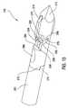
- FIG. 13is a perspective assembly view of the pivot pin and blade positioned within the cement cannula
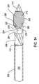
- FIG. 14is a cross-sectional view of the cement cannula, blade, and pivot pin shown in FIG. 13 ;
- FIG. 15is a side perspective view of the distal end of the cavity creator showing the blade seated within the tip and access cannula;
- FIG. 16is an exploded view of the proximal end of the cavity creator
- FIG. 17is a cross-sectional view of the proximal end of the cavity creator
- FIG. 18is a perspective view of one (1) half of the knob in which the inner portion can be viewed;
- FIG. 19is a perspective view of one (1) half of the knob in which the outer portion can be viewed;
- FIG. 20is a perspective view of the stylet, including the luer cap;
- FIG. 21is a cross-sectional view of the luer cap shown in FIG. 20 ;
- FIG. 22is a perspective view of the handle cap
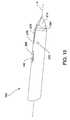
- FIG. 23is a perspective view of the cement cannula in which the blade is deployed
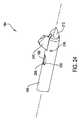
- FIG. 24is a perspective view of the distal end of the access cannula in which the blade is deployed;
- FIG. 25is a flowchart representing one embodiment of a method of using the cavity creator
- FIG. 26Ais a cross sectional view of a bone where the cavity creator of this invention is in the bone forming a cavity;
- FIG. 26Bis a cross sectional view of the bone after the cavity was created
- FIG. 26Cis a cross sectional view of the bone wherein a plume of cement is discharged from the cavity creator into the cavity;
- FIG. 27is a side view of an alternative luer hub of this invention.
- FIG. 28is a perspective view of the underside of an alternative stylet cap of this invention.
- FIG. 29is a cross sectional view of how the stylet cap of FIG. 28 engages the luer hub of FIG. 27 .
- distalrefers towards the site to which the cavity creator is applied; “proximal” means away from the site to which the cavity creator is applied, toward the practitioner holding the cavity creator.
- proximalmeans away from the site to which the cavity creator is applied, toward the practitioner holding the cavity creator.
- the term “substantially” or “approximately” as used hereinmay be applied to modify any quantitative representation that could permissibly vary without resulting in a change in the basic function to which it is related.
- FIG. 1is a perspective view of cavity creator 100 of this invention inserted into vertebra 55 of a patient 50 .
- Cavity creator 100comprises handle 110 , knob 140 , and an outer tube, access cannula 160 .
- Distal end 164 of access cannula 160is inserted into patient's 50 vertebra 55 .
- Handle 110 and knob 140are located at the proximal end of access cannula 160 .
- FIGS. 2 and 3illustrate cavity creator 100 in which handle 110 , knob 140 , access cannula 160 , and handle cap 180 can be seen.
- Access cannula 160is a substantially hollow elongated tube and comprises proximate end 162 and an opposed distal end 164 .
- Handle 110is rigidly secured to proximal end 162 of access cannula 160 .
- Tip 170is attached to the distal end of an inner tube, cement cannula 200 (see FIG. 13 ).
- Tip 170extends forward from distal end 164 of access cannula 160 .
- Tip 170functions as the component that punctures the patient's skin and vertebra or other bone into which cavity creator 100 is inserted.
- the cement cannula 200has a lumen 202 that extends axially therethrough (see FIG. 13 ).
- the cement cannula 200is positioned substantially within the access cannula 160 .
- Blade 210is pivotally connected to access cannula 160 and seated within cement cannula 200 .
- Stylet 230is a substantially solid elongated rod that is removably positioned within cement cannula 200 .
- Handle cap 180keeps stylet 230 within cavity creator 100 until the practitioner intends to remove stylet 230 from cavity creator 100 .
- knob 140When knob 140 is rotated about Axis A, cement cannula 200 functions as a drive member by being longitudinally displaced relative to access cannula 160 . This displacement of the cement cannula 200 pushes the pivoting blade 210 against the access cannula. This displacement of blade 210 causes the blade to rotate about pivot pin 220 to extend blade 210 radially outward from cavity creator 100 or access cannula 160 . Cavity creator 100 is then rotated and/or raised and lowered so that blade 210 can scrape the bone to create the cavity.
- knob 140is made of Nylon 6 6 plastic as manufactured by EMS-Grivory of Sumter, South Carolina, but can be made of any material commonly known and used in the art having similar characteristics.
- Handle cap 180extends over knob 140 and is removably secured to handle 110 to prevent removal of stylet 230 and rotation of knob 140 . Handle cap 180 also allows the practitioner to use a hammer or other device to aid in inserting cavity creator 100 into the vertebra without damaging the other components of cavity creator 100 . Handle cap 180 is made of the same material as knob 140 , but can also be made of another material and need not be made of the same material as knob 140 .
- FIG. 4illustrates distal end 164 of access cannula 160 .
- Center bore 158extends end-to-end through access cannula 160 .
- a pair of diametrically opposed, rectangularly shaped slots 159extend proximally rearward from distal end 164 of access cannula 160 .
- Each slot 159is contiguous with access cannula bore 158 .
- a pair of holes 153is formed in access cannula 160 between the slots. Holes 153 are located immediately forward of proximal end 164 of slot 159 . Holes 153 are centered on a line located above the longitudinal axis of access cannula bore 158 .
- access cannula 160is formed to define discharge port 166 . More particularly, access cannula 160 is formed so that discharge port 166 is longitudinally aligned with one (1) of slots 159 . Access cannula 160 is shaped so that discharge port 166 has an elliptical shape.
- FIGS. 5 and 6illustrate handle 110 .
- Handle 110has a cylindrical neck 114 that forms the distal end of handle 110 .
- handle 110is formed to have cylindrical core 112 .
- Core 112has an outer diameter greater than that of neck 114 .
- a single arcuately shaped shoulder 113extends outwardly from an outer surface of core 112 .
- Shoulder 113has a distal end (not identified) that is V-shaped and directed towards the distal end of cavity creator 100 . More particularly, shoulder 113 is located on handle 110 so that the distally base of the shoulder points to access cannula slot 159 from which blade 210 emerges.
- the proximal end of core 112has a flat shape.
- Two opposed steps 108 formed integrally with core 112extend upwardly from the opposed sides of the proximal end of core 112 .
- Steps 108have a length greater than that of the diameter of core 112 such that each step 108 extends outwardly from core 112 .
- One (1) tab 116extends upwardly from each step 108 .
- Each tab 116generally has a cross-sectional shape of slice section through the end of a circle.
- Tabs 116are located so that each tab 116 is slightly set back from the horizontal surface-vertical surface edge of step 108 with which tab 116 is integral.
- Each tab 116is further formed to have around top surface 117 a lip 106 that projects outwardly around the curved outer surface of tab 116 .
- Opposed arms 118project outwardly from handle core 112 .
- Each arm 118is in the form of a three-section structure (individual sections not identified).
- a first section of each arm 118projects outwardly from the distal end of core 112 , adjacent handle neck 114 .
- a second section of an individual arm 118extends upwardly from the outer end of the first section.
- Each arm 118has a third section that extends inwardly from the top of the second section.
- the third section of each arm 118curves downwardly and connects to the adjacent step 108 .
- the first and second sections of each arm 118are generally planar structures.
- the third section of each arm 118is formed to so that as arm 118 approaches adjacent step 108 , the thickness of arm 118 increases.
- a downwardly extending recess 120is formed in the top surface of the third section of each arm 118 .
- handle 110is shaped so that each recess 120 is defined by abutting horizontal and vertical surfaces on arms 118 (surfaces not identified).
- Handle 110is further formed to define groove 102 in each recess-defining vertical surface of arm 118 .
- Each groove 102extends the width of the vertical surface and is located a short distance above the horizontal surface that defines the base of recess 120 .
- Finger 101extends inwardly from the third section of each arm 118 .
- Each finger 101extends from the surface of the associated arm 118 that curves downwardly towards the end of the adjacent step 108 .
- Fingers 101project over and above the horizontal surfaces of the adjacent steps 108 .
- Each finger 101is generally in the form of an elongated bar that extends the width of arm 118 from which each finger 101 extends.
- a small groove 126is formed in the inner face of each finger that is directed to the opposed finger 101 .
- Each groove 126extends the top to bottom length of finger 101 with which groove 126 is integral. Grooves 126 are located along the top-to-bottom longitudinal axes of fingers 101 .
- Two grooves 127 and 128are formed on the vertical surface of a single one (1) of steps 108 . Both grooves 127 , 128 are aligned on axes parallel to the longitudinal axis of cavity creator 100 .
- a first of the grooves, groove 127has a relatively shallow depth.
- the second groove, groove 128is of deeper depth than groove 127 .
- Both grooves 127 and 128have a generally circular cross sectional profile. Groove 128 has a smaller radius of curvature than groove 127 .
- Handle 110is further formed with a stop 130 ( FIG. 16 ).
- Stop 130is in the form of a rectangular and planar shaped web that extends downward from one finger 101 to the horizontal surface of the step 108 below the finger. More particularly, stop 130 is located above the step 108 opposite the step 108 in which grooves 127 and 128 are formed. Stop 130 should also be understood to project outwardly from the vertical wall (not identified) that extends between the associated finger 101 and step 108 .
- Handle 110is further formed to have a pair of opposed webs 104 .
- Webs 104extend outwardly from opposed surfaces of handle core 112 .
- Each web 104extends bottom-to-top from the opposed surfaces of handle arm 118 first and third surfaces between which web 104 is located. Webs 104 thus provide structural strength to handle 110 .
- First and second contiguous and coaxial bores 122 and 124extend through handle core 112 and neck 114 .
- Bore 122extends downwardly from the top surface of handle core 112 . (Not identified is the small tapered counter bore that forms the actually opening in core 112 top surface.)
- Bore 122has a diameter that allows cement cannula 200 to slidably move within the bore 122 .
- the distal end of bore 122opens into bore 124 .
- Bore 124extends from bore 122 to the distal end of handle neck 114 .
- Bore 124has a diameter greater than that of bore 122 . More particularly, bore 124 has a diameter that allows access cannula 160 to be seated and secured in bore 124 .
- access cannula 160is heat staked, overmolded, or adhesively secured in bore 124 .
- handle steps 108are not equidistantly spaced apart from bore 122 .
- the step 108 in which grooves 127 and 128 are formedis closer to bore 122 than the opposed step 108 . Consequently, the step 108 in which the grooves 127 and 128 is longer in width, the lateral axis across the handle 110 , than the opposed step 108 .
- FIG. 8is a perspective view of cement cannula 200 .
- Cement cannula 200is also a substantially hollow elongated shaft and comprises distal end 204 .
- Cement cannula 200has an outer diameter that allows the cement cannula to slidably move within bore 158 of access cannula 160 .
- Lumen 202extends axially through cement cannula 200 .
- Cement cannula 200is further formed to have at distal end 204 a forwardly extending lip 274 ( FIG. 13 ). Lip 274 is generally arcuately shaped.
- Cement cannula 200is made of 304 non-hardened stainless steel.
- Tip 170is made of 17 - 4 pre-hard, heat treatable stainless steel.
- cement cannula 200 and tip 170can be made of any sufficiently corrosion resistant, biocompatible, rigid material and that cement cannula 200 and tip 170 can also be made of the same material.
- Luer hub 240is secured to proximal end 206 of cement cannula 200 .
- luer hub 240is formed from a single piece of plastic that is shaped to have base 242 and head 244 coaxial with base 242 . Both base 242 and head 244 are generally cylindrical. Head 244 is located above base 242 and has an outer diameter slightly greater than that of base 242 .
- a first bore 247extends upwardly from the distal end of base 242 . Bore 247 is dimensioned to receive the proximal end of cement cannula 200 . Bore 247 extends approximately one quarter the way up luer hub 240 from the bottom of hub base 242 .
- a second bore, bore 248extends upwardly through hub base 242 from bore 247 towards the top end of hub base 242 .
- Bore 248has a diameter less than that of bore 247 . More particularly, bore 248 has a diameter that allows stylet 230 to be slidably advanced/retracted through bore 248 .
- Luer hub 240has a third bore, bore 249 , that extends upwardly from second bore 248 . Bore 249 has a diameter greater than the diameter of stylet 230 .
- Third bore 249is located in and extends axially through hub head 244 . Bore 249 has a diameter that is greater than the diameter of bore 248 .
- bore 249also has a diameter greater than that of bore 247 .
- third bore 249is also tapered inward along its length from its proximal end to its distal end. The taper allows luer hub 240 to connect to a luer fitting of a standard syringe or other medical device. For example, while the distal end of tube 42 is not shown, this tube would have a fitting that allows the tube to be connected to luer hub 240 .
- Threading 252is disposed about the outer surface of hub base 242 . As discussed below, threading 252 engages complementary threading integral with knob 140 to extend and retract cement cannula 200 . Luer hub 240 is also formed with threading 254 around hub head 244 . Threading 254 is dimensioned to engage complementary threading associated with a luer fitting used to attach flexible delivery tube 42 to cement cannula 200 .
- FIG. 10illustrates tip 170 , which is attached to distal end 204 of cement cannula 200 .
- Tip 170is generally cylindrically shaped.
- Tip 170is formed to have a solid, diamond shaped head 212 .
- the geometry of head 212allows head 212 to puncture the soft and hard tissue into which cavity creator 100 of this invention is inserted.
- Tip 170is shaped to form bore 214 (see FIG. 14 ) that extends forward from the proximal end of tip 170 .
- Bore 214angles upward into cement discharge port 266 formed along an outer circumferential surface of tip 170 .
- an arcuate step 272is formed in tip 170 around the proximal end of tip 170 .
- Step 272does not extend circumferentially around tip 170 and is not contiguous with the opening of bore 214 .
- cement cannula lip 274seats in the void space defined by step 272 .
- This lip-in-slot arrangementensures that during manufacture, tip 170 assumes the proper orientation relative to cement cannula 200 .
- This lip-in-slot arrangementalso facilitates the torsional strength of the tip-to-cement cannula coupling.
- tip 170is also formed to have blade slot 216 that is located proximal to tip head 212 and forward of discharge port 266 .
- Blade slot 216extends through tip 170 from the top to the bottom.
- Supplemental slot 218which is contiguous with blade slot 216 , extends rearwardly in tip 170 from blade slot 216 .
- tip 170is formed so that the longitudinal axis of discharge port 266 lies in the longitudinal plane around which slots 216 and 218 are centered.
- Discharge port 266is centered along a plane that is perpendicular to the longitudinal plane around which slots 216 and 218 are centered.
- supplemental slot 218does not extend completely through the opposed top and bottom sides of tip 170 .
- Tip 170is also formed to define parallel notches 224 on either side of the open end of supplemental slot 218 .
- the bases of notches 224lie along a plane that is perpendicular to the longitudinal plane around which slots 216 and 218 are centered.
- the proximal ends of each notch 224start along a plane located forward of discharge port 266 .
- Notches 224extend forward along tip 170 to intersect the proximal end of blade slot 216 .
- Parallel slots 226extend downwardly from the base of each notch 224 . Slots 226 , which start at a position approximately in the middle of each notch 224 , extend forward at approximately a forty five degree (45°) angle towards blade slot 216 . As shown, each slot 226 traverses the entire thickness of each opposing side of tip 170 .
- FIG. 11is a perspective view of blade 210 .
- Blade 210is formed from material such as 17 - 4 pre-hard, heat treatable stainless steel, but can also be made of any commonly known and used material in the art having similar characteristics.
- Blade 210comprises body 222 that has a generally planar shape.
- Body 222has main section 225 that has a top-to-bottom height substantially equal to the outer diameter of access cannula 160 . Inherently, this dimension is greater than the top-to-bottom height of tip blade slot 216 .
- Body main section 222has a leading edge 228 that has a curved cross-sectional profile.
- Body main section 222has trailing edge 229 (see FIG. 14 ).
- the leading and trailing edges, 228 and 229 respectively, of blade 210have a common radius of curvature substantially equal to the radius of curvature of access cannula 160 .
- Blade body 225has distal face 227 is the most distally directed surface of the blade body 225 .
- Distal face 227extends between the opposed sides of the blade body 225 .
- Face 227generally has a rounded shape.
- Face 227is further formed to have a planar taper 231 that extends forward from the distal end of trailing edge 229 . Taper 231 provides clearance for blade 210 so the blade can rotate in and out of tip blade slot 216 .
- Blade body 225is further formed to have a tail 270 that extends rearward and is coplanar with main section 225 .
- Tail 270has a top to bottom height less than that of body main section 225 . More particularly, blade 210 is shaped so that when blade main section 225 seats in blade slot 216 , blade tail 270 seats in supplemental slot 218 and tail 270 extends into the void space subtended by tip notches 224 . The upper edge of blade tail 270 is located below leading edge 228 of main section 225 .
- Blade tail 270further comprises tapered corners 273 located forward of the proximal end of blade tail 270 .
- Throughhole 276extends side-to-side through blade tail 270 immediately below the top edge of tail 270 .
- Opposed posts 278extend outwardly from the opposed sides of blade tail 270 .
- Posts 278which are cylindrical, are located forward and below throughhole 276 .
- Posts 278fit within slots 226 .
- FIG. 12is a perspective view of pivot pin 220 .
- Pivot pin 220is substantially cylindrical and comprises two (2) opposing outer surfaces 238 . Outer surfaces 238 are slightly arcuate to correspond to the rounded outer surface of access cannula 160 . While not apparent in the drawings, pivot pin 220 is slightly tapered along its length, with the diameter of the of one end being slightly larger than the diameter of the opposed end.
- pivot pin 220extends through blade throughhole 276 .
- Blade 210is positioned in tip 170 so that body main section 225 of blade 210 seats in tip blade slot 216 and body tail 270 seats in supplemental slot 218 .
- the opposed side edges of blade 210project beyond the outer circumferential surface of tip 270 .
- each post 278seats in an adjacent tip slot 226 .
- the opposed ends of pivot pin 220extend through and over and beyond notches 224 .
- the arcuately shaped opposed outer surfaces 238 of pivot pin 220are flush with the outer circumferential surface of access cannula 160 .
- distal end 164 of cement cannula 200 and the portion of tip 170 proximal to head 212are seated within access cannula bore 158 .
- Tip blade slot 216is in registration with the opposed access cannula slots 159 .
- the opposed ends of pivot pin 220are fixedly secured via press fit in the opposed access cannula holes 153 .
- One access cannula hole 153is slightly larger than the other such that each end of pivot pin 220 can be press fit within each access cannula hole 153 .
- the end of pivot pin 220 having a smaller diameteris slid through access cannula hole 153 having a larger diameter and into access cannula hole 153 having a smaller diameter. The result is that pivot pin 220 can be slid along the width of access cannula 160 , but each end press fit within the corresponding access cannula hole 153 .
- Lumen 202leads into tip bore 214 at approximately a 30° angle relative to Axis A to form discharge port 266 .
- Tip 170further includes projection 282 , which is below tail 270 of blade 210 and extends forward to form the bottom surface of tip 170 .
- Projection 282is therefore arcuately shaped.
- Projection 282also forms the bottom of supplemental slot 218 , but does not extend to head 212 . Because it does not extend along the entire length of tip 170 , projection 282 allows blade slot 216 to traverse tip 170 from top to bottom.
- blade 210when in the retracted position (for example, as shown in FIG. 15 ), blade 210 is substantially flush with access cannula 160 so as not to catch on tissue when cavity creator 100 is inserted into the patient. Also visible in FIG. 15 is tapered surface 284 around the distal end of tip 170 . Tapered surface 284 is angled inward between the diameter of access cannula 160 and approximately the outer diameter of head 212 . Tapered surface 284 further reduces the likelihood of access cannula 160 catching tissue when cavity creator 100 is inserted in the patient.
- blade 210extends forward from tip 170 as close as possible to the distal end and that cement discharge port 266 is open as close as possible to the distal end of the tip 170 .
- bladeis formed with taper 231 .
- Taper 231has a slope that makes it possible to minimize the distance between the distal end of blade 210 and the adjacent inner wall of tip 170 that defines the distal end of blade slot 216 .
- the proximally directed corners 269 of blade tail 270are tapered (tapers not identified). These tapers reduce the spacing between the blade tail 270 and the distally directed internal surface of the tip that defines the proximal end of slot 216 .
- the maximum distance the distal end of the tip head 214 and the proximal ends of slots 224is no greater than 0.200 inches. In more preferred versions of the invention, this maximum separation between these two features of tip 170 is no more than 0.150 inches. In turn, this makes it possible to fabricate tip 170 so that the cement discharge port 266 opens within 0.250 inches of the distal end of the tip and, in more preferred versions of the invention, within 0.200 inches of this end.
- bore 214should be relatively wide to facilitate the discharge of cement with as free as flow as possible. In some versions of the invention bore 214 should have a diameter of at least 0.050 inches.
- FIGS. 16 and 17are exploded and cross-sectional views, respectively, of the proximal end of cavity creator 100 .
- Knob 140is shaped to have a body 142 and two (2) downwardly extending rings 146 , 148 .
- the first ring 146extends downward from the outer portion of the bottom surface of body 142 .
- the second ring 148extends downward from the center of the bottom surface of body 142 and forms bore 150 .
- First ring 146is outward of second ring 148 , which are separated by gap 152 .
- Second ring 148comprises two (2) sections (not identified).
- the first sectionis proximate to knob body 142 .
- the second sectionis below the first section and has a smaller diameter than the first section.
- the two (2) sectionsdefine a step 143 therebetween.
- the second sectionit should be understood, has a diameter slightly less than the distance between handle steps 108 .
- Bore 150 of second ring 148is formed to have threading 154 on its inner surface. Threading 252 on the outer surface of base 242 of luer hub 240 engages complementary threading 154 . Luer hub 240 therefore converts the rotation of knob 140 to longitudinal displacement of cement cannula 200 to function as a drive member to extend and retract blade 210 .
- First ring 146comprises inwardly extending lip 256 .
- tabs 116 of handle 110extend upward into gap 152 .
- Lip 256is disposed below the outwardly projecting lips 106 integral with handle tabs 116 .
- the lip-under-lip arrangementallows knob 140 to rotate, but does not allow it to be upwardly removed from handle 110 .
- knob 140comprises two (2) matable halves.
- the male half of knob 140includes six (6) mating members 156 .
- the female half(not shown) includes six (6) corresponding receiving members for engaging mating members 156 .
- Mating members 156 and the corresponding receiving membersare press fit together. It should be understood that the two (2) halves of knob 140 can alternately be secured to one another by a greater or lesser number of mating members 156 and receiving members, by heat, an adhesive, screws, or any combination thereof.
- opening 138is dimensioned to receive luer cap 260 .
- Knob body 142is further shaped to have notch 144 that extends radially outwardly from opening 138 .
- Notch 144is sized to allow luer cap tab 255 (see FIG. 21 ) to pass therethrough when properly aligned in order to remove stylet 230 .
- Each half of knob 140includes one half of slot 134 such that when mated, the halves form slot 134 .
- Slot 134is formed as part of knob top surface 136 and that part of top surface 136 forming slot 134 has a thinner thickness as compared to the remaining portion of knob top surface 136 .
- Slot 134extends along the opposing inner facing mating surfaces of each half of knob 140 and extends from the outer edge of opening 138 to the outermost edge of knob 140 . Slot is further oriented substantially perpendicular to notch 144 .
- Detents 288are oriented along axes parallel to the longitudinally axis of cavity creator 100 . In the drawings, not all four (4) detents 288 are visible. Specifically, in the embodiment shown, a first detent 288 (on the left of body 142 ) is positioned on outer surface 145 of knob 140 . The other half of knob 140 has a similarly located detent 288 . Detent 288 (located on the right of body 142 ) is only a half of a detent.
- the other half of knob 140has a corresponding half detent 288 that, when the two (2) halves of knob 140 are mated, form a full detent 288 .
- each halffurther includes a second half detent 288 on the opposite mating side (not visible). The result is four (4) full detents 288 .
- Detents 288are all spaced apart from one another at approximately ninety degree ( 90 °) increments.
- Ribs 286are also visible on the outside of body 142 . Because the practitioner may be wearing gloves and/or have fluids on their hand, ribs 286 allow the practitioner to better grip knob 140 . Knob 140 can have any number of ribs 286 , and it is not intended that ribs 286 be limited to any width, depth, spacing between, or orientation. As an alternate gripping mechanism, knob 140 can further include studs, textured portion(s), an elastomeric material positioned on any portion or entirely around knob 140 , or any combination thereof.
- slot 290 and corners 292 , 293are also visible in FIGS. 18 and 19 .
- Slot 290is formed in first ring 146 and extends circumferentially around an outer section of ring 146 . Each half that forms knob 140 is formed with slot 290 . Slots 290 are present for manufacturing reasons and are otherwise not relevant to this invention. Corners 292 , 293 are rounded surfaces where each vertical surface meets the horizontal surfaces of rings 146 , 148 . The rounded surfaces are also not integral to the invention.
- Knob second ring 148is further formed to have a single outwardly extending rib 172 seen best in FIG. 19 .
- Rib 172is dimensioned to fit in handle grooves 127 and 128 . More particularly, rib 172 has a radius of curvature that is less than the radius of curvature of groove 127 .
- Knob 140is further formed to have a single tab 235 , seen in cross section in FIG. 17 . Tab 235 extends radially outwardly from the distal end of knob first ring 146 .
- FIG. 20shows stylet 230 , including luer cap 260 .
- Stylet 230is a substantially solid rod and comprises distal end 234 and proximal end 236 .
- Stylet 230has an outer diameter that allows stylet 230 to slip fit within cement cannula lumen 202 .
- Luer cap 260is fitted over and secured to proximal end 236 of stylet 230 .
- Plug 232is secured to distal end 234 of stylet 230 and made of a flexible material. Stylet 230 and plug 232 are collectively shaped so that plug 232 extends forward of cement cannula 200 .
- Stylet 230is shaped so that the distal end of the stylet does not extend into tip 170 .
- stylet plug 232extends through tip bore 214 towards the access cannula discharge port 166 .
- Stylet plug 232does not extend out of the access cannula discharge port 166 .
- This design featuresubstantially eliminates the possibility that, when the cavity creator 100 is inserted in the patient, tissue will catch in discharge ports 166 and 266 .
- Stylet 230is held in place by the frictional engagement between stylet plug 232 and bore 214 to prevent rotation of stylet 230 . Because stylet plug 232 is made of a flexible material, it can be slid along lumen 202 of cement cannula 200 and bend off axis from the stylet 230 to extend into tip bore 214 .
- Stylet plug 232is made of an elastomeric material such as that manufactured under the trademark Santoprene® by Advanced Elastomer Systems of Akron, Ohio but can be made of any other natural or man-made material having similar flexibility, durability, and biocompatibility characteristics, including silicone.
- Stylet 230is made of 316 stainless steel, but can alternately be made of another sufficiently corrosion-resistant, biocompatible, and strong material, including but not limited to 420 stainless steel, 304 stainless steel, and 17 - 4 pre-hardened stainless steel.
- Luer cap 260is made of the same material as handle 110 , but can also be made of any material commonly known and used in the art having similar characteristics.
- Luer cap 260is generally cylindrical and comprises body 262 , outer skirt 267 , inner skirt 268 , recess 258 between skirts 267 , 268 , tab 255 , and luer boss 280 .
- Body 262is substantially cylindrical.
- Luer boss 280is integrally formed with and positioned on the proximal end of luer body 262 .
- Boss 280is also substantially cylindrical in shape and extends outward from body 262 .
- Luer boss 280also extends upward beyond the top surface of knob 140 when stylet 230 is positioned within cavity creator 100 . Luer boss 280 allows the practitioner to grasp luer cap 260 .
- outer skirt 267 and inner skirt 268are At the distal end of luer body 262 .
- Outer skirt 267is positioned outward of luer body 262 to approximately the same diameter as luer boss 280 and extends downward from body 262 .
- Inner skirt 268extends downward from body 262 below outer skirt 267 .
- Inner skirt 268is further formed to have a tapered outer diameter that increases from the distal end of skirt 268 .
- Inner skirt 268 , body 262 , and a portion of boss 280also form a generally cylindrical bore 264 .
- Bore 264is sized to receive proximal end 236 of stylet 230 .
- Luer cap 260is overmolded onto stylet 230 .
- Tab 255extends radially outward from outer skirt 267 and prevents stylet 230 from being unintentionally removed from lumen 202 . Specifically, in order to remove stylet 230 , tab 255 must be aligned with notch 144 (see FIG. 18 ) in top surface 136 of knob 140 .
- FIG. 22illustrates cap 180 .
- Cap 180can be made out of the same material from which handle 110 is formed.
- Cap 180is formed as a single piece component shaped to have head 182 in form of a flat surfaced dome. As seen best in FIG. 17 , the undersurface of head 182 is shaped to have cavity 184 . Cavity 184 is dimensioned to receive the top of luer cap 260 .
- Two arms 186extend radially outwardly from the opposed sides of head 182 . Each arm 186 is generally in the form of a bar that curves downwardly as arm 186 extends away from head 182 . Extending downwardly from the undersurface of each arm 186 is rib 188 .
- Ribs 188have a side-to-side width less than arms 186 from which ribs 188 extend. Ribs 188 mate with slot 134 on top surface 136 of knob 140 to prevent rotation of knob 140 until knob cap 180 is removed.
- Fingers 190extend downwardly from the undersurface of each arm 186 . Fingers 190 are located inwardly of the outer ends of each arm 186 . Each rib 188 abuts the end of the associated finger 190 . Fingers 190 are formed to have a T-shaped cross sectional profile such that each finger 190 has flange 192 . Cap 180 is further shaped so that finger flanges 192 are directed inwardly, towards each other. Flanges 192 provide structural support for when cavity creator 100 is hit with an impact device. Knuckles 195 extend outwardly from each finger flange 192 . Knuckles 195 are thus directed inward toward each other. Each knuckle 195 is in the shape of a triangle that has a notch that extends inwardly from the apex (notch not identified).
- Cap 180is further formed so that fingers 190 have widths that allow fingers 190 to seat in the opposed handle recesses 120 .
- knuckles 195seat in grooves 102 formed in handle 110 .
- the seating of cap knuckles 195 in handle grooves 102serves to releasably hold cap 180 to handle 110 .
- handle cap 180is shaped so that when handle cap 180 is seated over the rest of cavity creator 100 , as seen in FIG. 17 , there is first gap 174 between the top of luer cap 260 and the adjacent undersurface of cap head 182 . There is also a smaller and outwardly directed second gap 176 between ribs 188 below each arm 186 and top surface 136 of knob 140 .
- cavity creator 100can be used by performing the following steps. It should be noted that not every step need be included in every procedure involving cavity creator 100 and that additional and/or equivalent steps can be included without departing from the spirit and scope of the invention.
- FIG. 25is a flowchart representing one (1) method 300 of using cavity creator 100 of the instant invention.
- the following stepscan be performed: inserting the cavity creator 310 , extending the blade 320 , creating a cavity 330 , retracting the blade 335 , withdrawing the stylet 340 , connecting the cavity creator to a canister 350 , injecting cement or another material into the cavity through the cavity creator 360 , and removing the cavity creator 370 .
- knob detents 288Upon assembly of cavity creator 100 , a pair of opposed knob detents 288 are seated in handle finger grooves 126 . Knob rib 172 is, at this time, seated in handle groove 127 .
- Step 310comprises inserting cavity creator 100 into vertebra 55 or other bone tissue, whether additional tissue must be traversed (for example, through skin over vertebra 55 ) or vertebra 55 or other bone is exposed.
- additional tissuemust be traversed (for example, through skin over vertebra 55 ) or vertebra 55 or other bone is exposed.
- a small incisionis made to form an opening in the skin at which the cavity creator 100 is to be inserted.
- the actual insertionis typically done by hand, but a hammer or other impact device can also be used to insert cavity creator 100 .
- the head of the hammeris brought down against cap head 182 .
- the force of this impactis transferred through cap arms 186 and fingers 190 to handle 110 .
- the forceis transmitted through access cannula 160 to tip 170 .
- cap head 182is spaced above stylet cap 260 this impact force is not transferred to stylet 230 .
- the driving of cannulas 160 and 200 into the bonedoes not result in the simultaneous further driving of stylet 230 out of access cannula discharge port 166 .
- cap arms 186will flex.
- the degree of arm flexureis such that the arms 186 do not contact and therefore do not transfer energy to the underlying surfaces of knob 140 . This flexure thus substantially eliminates the likelihood that the application of energy to cap 180 will result in structural failure of cap 180 or the underlying knob 140 .
- blade 210is in the retracted state, the longitudinal axis of the blade is at least parallel to, if not aligned with, the longitudinal axis of access cannula 160 .
- stylet tip 232is disposed in tip bore 214 . The presence of tip 232 in bore 214 during the insertion process reduces the likelihood that, during the insertion process, tissue will catch in the access cannula discharge port 166 or tip bore 214 .
- step 320handle cap 180 is first removed from the rest of cavity creator 100 .
- the removal of cap 180moves cap ribs 188 away from knob slot 134 .
- the practitionermay rotate cavity creator 100 so blade 210 will extend into the specific section of bone in which the cavity is to be formed.
- the longitudinal axis of the bladebecomes angled relative to the longitudinal axis of the access cannula 160 .
- cavity creator 100is rotated until the base of handle shoulder 113 points to the section of the bone into which the practitioner wants blade 210 to extend.
- Blade 210is extended by rotating knob 140 .
- knob rib 172rotates out of handle groove 127 .
- Handle 110is dimensioned such that during this displacement of knob 140 , rib 172 does not abut the surface of handle 110 that defines groove 127 . Accordingly, this displacement of rib 172 does not provide tactile feedback to the practitioner that knob 140 is being rotated.
- the initial rotation of handle 140also simultaneously forces knob detents 288 out of handle grooves 126 .
- the abutment of detents 288 against the groove-defining surfaces of handle 110does provide a tactile feedback of knob 140 rotation.
- the inner or cement cannula 200longitudinally translates relative to the outer or access cannula 160 .
- Pivot pin 220is fixed relative to access cannula 160
- blade 210is positioned within cannulas 160 , 200 .
- cement cannula 200 and tip 170are longitudinally translated forward, the rear surfaces of tip 170 that define slots 226 are pushed against posts 278 on blade 210 , as seen in FIG. 23 . This action pushes blade 210 outwardly so that blade 210 rotates around pivot pin 220 and extends out of one of the access cannula slots 159 as seen in FIG. 24 .
- knob 140also rotates knob notch 144 so that the notch moves out of registration with stylet cap tab 255 .
- This new orientation of knob 140 relative to luer cap tab 255places knob 140 in the position in which knob 140 blocks removal of luer cap tab 255 and therefore the whole of stylet 230 , from the rest of cavity creator 100 .
- the plug 232is in an off axis position to stylet 230 itself.
- This off axis position of stylet plug 232inhibits the manual rotation of stylet 230 that could place luer cap tab 255 in registration with knob notch 144 .
- the inhibiting of the rotation of stylet 230 and the reorientation of knob 140mean that when knob 140 is rotated to extend blade 210 , stylet 230 is blocked from removal from the rest of the assembly.
- Detents 288provide an indication of the extent to which knob 140 is rotated from the initial state so as to provide an indication of the degree of blade extension. Specifically, once knob 140 is rotated 90° from the initial state, a second pair of opposed detents 288 seat in handle grooves 126 to provide an indication of the quarter-turn rotation of knob 140 . This means that the blade 210 is extended approximately one-quarter from its retracted state. The rotation of knob 140 180° results in the opposed pair of detents 288 that were initially seated in the handle grooves 126 reseat in the grooves.
- each detent 288seats in a groove 126 opposite the groove 126 in which the detent 288 was initially seated.
- This seating of detents 288provides tactile feedback that knob 140 has undergone a half turn of rotation.
- the second pair of opposed detents 288again seat in handle grooves 126 .
- the movement of detents 288 in and out of grooves 126provides the indication that knob 140 has undergone more that a three-quarters turn rotation. It should therefore be understood that the blade 210 should be considered about three-quarters fully extended.
- knob 140is not rotated a full 360°. Instead, the knob is able to rotate between typically between 330° and 350°. In some versions of the invention, the knob is able to rotate between 340° and 345°.
- knob rib 172seats in handle groove 128 . The seating of rib 172 in groove 128 provides the tactile feedback that the knob is fully rotated. Should one try to force further rotation of knob 140 , knob tab 235 abuts handle stop 130 to prevent such movement.
- the cavityis created in the bone, step 330 .
- This stepis performed by the practitioner rotating cavity creator 110 .
- This rotationcauses blade 210 to move against and scrape the porous cancellous tissue 306 that forms the center of the bone 302 as seen in FIG. 26A .
- the dense cortical tissue 304 that forms the outer shell of bone 302is represented by dense stippling; the inner porous cancellous tissue 306 is represented by sparse stippling.
- the grinding of the cancellous tissue 306forms a cavity 308 in the bone 302 where this tissue was previously located.
- the practitioneris able to selectively control where in the bone 302 the cavity 308 is created by regulating the arc through which blade 210 is rotated.
- the practitionermonitors blade position by monitoring the location of the distally directed base of the handle shoulder 113 .
- cavity creator 100can be displaced longitudinally. This allows the practitioner to set the length of the cavity 308 .
- the practitionermay chose to first partially extend the blade and create a small cavity. Once this small cavity is created the practitioner may then more fully extend the blade 210 to create a larger cavity.
- Cavity creator 100can be completely rotated to form a 360° cavity around cavity creator 100 or can be rotated to an extent less than complete rotation to create a cavity only around a portion of cavity creator 100 . Cavity creator 100 can, while being rotated, also be moved longitudinally to create a cavity that is longer than the length of blade 210 .
- stylet plug 232is disposed is disposed in tip bore 214 .
- Plug 232prevents tip bore 214 and cement cannula lumen 202 from clogging, which could inhibit the subsequent delivery of cement.
- tip discharge port 266moves out of registration with the access cannula discharge port 166 . More particularly, the section of the tip 170 proximal to discharge port 266 moves under the access cannula discharge port 166 . This further blocks the flow of material into tip bore 214 and cement lumen 202 .
- blade 210is retracted, step 335 , by reversely rotating knob 140 .
- the rotation of knob 140causes cement cannula 200 to retract proximally rearward. This results in blade pins 278 being pressed against the surfaces of tip 170 that define the distal ends of slots 226 . The pressing of the blade pins 278 against these surfaces rotates blade 210 about pivot pin 220 to the retracted position.
- knob notch 144is rotated back into alignment with luer cap tab 255 .
- stylet 230can be removed from cavity creator 100 , step 340 .
- Step 350comprises connecting cavity creator 100 to cartridge 40 .
- Bone cement or other filler material to be injected into the cavityis contained in cartridge 40 .
- Cartridge 40is mechanically connected to cavity creator 100 by flexible tubing 42 or other appropriate means.
- flexible tubing 42is connected to cavity creator 100 by a threaded fitting (not shown) on flexible tubing 42 that mates with threading 254 on luer hub 240 .
- Step 360comprises injecting the bone cement or other filler material into to the cavity.
- the materialis ejected from cartridge 40 using plunger 44 , but can be ejected using any other mechanism or device.
- the ejected materialpasses through flexible tubing 42 , through lumen 202 , cement cannula discharge port 266 and access cannula discharge port 166 into the cavity 308 as seen in FIG. 26C .
- a plume of cement 309is seen discharged from the access cannula port 166 into the cavity 308 .
- the mass of cementfixates fractures present in the bone.
- the injection of other filler material into the bone cavityprovides the same and/or other therapeutic benefit.
- the present inventionis not limited to the particular material being injected or the type of bone into which the material is being injected. Such a procedure allows the practitioner to control the time at which the material being injected (that is, early in the curing process in which the material is less viscous or later in the curing process in which the material is more viscous), the volume of the material being injected, as well as the pressure at which the material is injected.
- Step 370comprises removing cavity creator 100 from the patient. That is, once the material has been injected into the cavity, cavity creator 100 is extracted from the bone and any other tissue that cavity creator 100 passed through to get to the bone.
- a feature of this inventiontherefore is that it provides a single device for: penetrating the bone; forming the cavity in the bone; and functioning as the delivery conduit through which the filler material can then be introduced into the cavity.
- the need to use plural instruments to perform these stepsis therefore eliminated. Eliminating the need to position plural instruments in the bone both minimizes the complexity of the procedure and the overall amount of time it takes to perform the procedure.
- step 350 of connecting cavity creator 100 to cartridge 40can be performed between or during other steps of method 300 .
- cavity creator 100 and method of using samehas been shown and described primarily with respect to one (1) specific version, from the above description it should be clear that the same is not limited thereto, but is susceptible to numerous changes and modifications as known to a person of ordinary skill in the art.
- cavity creator 100need not include handle cap 180 .
- knob 140need not have ribs 286 or another means for helping the practitioner grasp cavity creator 100 .
- threading 254 on luer hub head 244is only one way by which delivery tube 42 can be attached to cement cannula 200 .
- delivery tube 42frictionally engages luer hub 240 such that threading 254 is unnecessary.
- the pivot pin 220may be welded to the access cannula 160 .
- the stylet 230may not be necessary in some versions of the invention to provide the stylet 230 with a flexible plug that extends towards the tip discharge port 266 .
- an alternative luer hub 390 seen in FIG. 27is disposed over the proximal end of the cement cannula 200 .
- Luer hub 390has the same basic features as luer hub 240 .
- Luer hub 390is further formed so that the top most threading 392 that receives the luer fitting is formed to have a break 394 .
- This version of the inventionincludes a stylet cap 402 , partially seen in FIG. 28 .
- Stylet cap 402includes the same basic features of stylet cap 260 .
- Stylet cap 402is further formed so that extending inwardly from the inner surface of outer skirt 267 there is finger 404 .
- the longitudinal axes of tab 255 and skirt finger 404are coaxial.
- the side-to-side width of finger 404is less than the side-to-side width of tab 255 .
- cap finger 404seats in the luer hub break 394 .
- the finger-in-break engagement of the hub 390 and cap 402prevents the stylet cap from rotating relative to the luer hub.
- the knob 140is rotated to extend the blade 210 , cement cannula 200 only undergoes translation motion, the cannula 200 does not rotate. Again such rotation causes the knob notch 144 to rotate out of registration with cap tab 255 .
- the stylet cap 402cannot be rotated to place the cap tab 255 in registration with knob notch 144 .
- the cap tab 255cannot be placed in registration with the notch 144 , removal of the stylet 230 from the rest of the cavity creator is blocked.
- alternate versions and geometries of the described features of the present inventionare possible.
- alternate versions of cavity creator 100may vary from what has been illustrated.
- blade 210has been shown as having a substantially rectangular cross-sectional shape.
- blade 210may be triangular, hooked, or have almost any other shape depending on the specific size and shape of the cavity to be created.
- head 212has been shown as having four facets to form a generally pyramid shape.
- head 212can have any alternate shape that still allows cavity creator 100 to be inserted into the bone in which the cavity is to be formed.
- handle 110can have any shape that provides the practitioner the ability to grasp cavity creator 100 .
- access cannula 160 and tip 170can be formed as one integrated element.
- the slots 224 in which blade pins 278 do not extend completely through tip 170the slots stop short of the outer circumferential wall of pin 170 . Adjacent each slot there is a small web. One side of the web defines a portion of the outer circumferential surface of the tip 170 ; the opposed surface defines the end of the associated slot. In these versions of the invention, the webs add strength to the tip when it is inserted into tissue or the cavity creator 100 is rotated.
- cavity creator 100 of this inventionmay be used with cement or filler delivery devices other than the disclosed cartridge 40 .
- a tube shaped cartridgemay be disposed in the access cannula lumen. This cartridge is preloaded with cement or filler. Once this cartridge is in place, a plunger drives the cement from the cartridge into tip bore 214 and discharge ports 266 and 166 .
- bone filler other than cementmay be supplied to the cavity created using the assembly of this invention.
- Other potential bone fillers than cementinclude: bone graft material or bone growth material.
- the fillers that can be delivered using this inventionare not limited to liquids and semi-solids. Solid implants like beads or other rigid fillers may be added using the assembly of this invention.
- a tabmay be attached to the cement cannula 200 .
- the practitionerslides the tab to cause displacement of the cement cannula in order to cause the desired extension/retraction of the blade 210 .
- an elongated rodmay be slidably mounted to the access cannula 160 .
- a rack of gear teethengage complementary teeth associated with the blade. The rod is extended/retracted in order to cause a similar displacement of the blade 210 .
- the cement cannulamay be provided with a finger that is biased to press into a notch in the stylet when the cement cannula is displaced in the forward direction. The seating of the finger in the notch blocks removal of the stylet. When the cement cannula is retracted proximally, the finger retracts from the stylet to allow removal of the stylet.
- the access cannulamay not have a lumen.
- this inventionis removed and a separate delivery cannula is used as the member for introducing filler material into the created cavity.
Landscapes
- Health & Medical Sciences (AREA)
- Surgery (AREA)
- Life Sciences & Earth Sciences (AREA)
- Orthopedic Medicine & Surgery (AREA)
- Biomedical Technology (AREA)
- Nuclear Medicine, Radiotherapy & Molecular Imaging (AREA)
- Engineering & Computer Science (AREA)
- Heart & Thoracic Surgery (AREA)
- Medical Informatics (AREA)
- Molecular Biology (AREA)
- Animal Behavior & Ethology (AREA)
- General Health & Medical Sciences (AREA)
- Public Health (AREA)
- Veterinary Medicine (AREA)
- Oral & Maxillofacial Surgery (AREA)
- Dentistry (AREA)
- Surgical Instruments (AREA)
Abstract
Description
Claims (28)
Priority Applications (2)
| Application Number | Priority Date | Filing Date | Title |
|---|---|---|---|
| US12/187,727US8246627B2 (en) | 2008-08-07 | 2008-08-07 | Cement delivery device for introducing cement into tissue, the device having a cavity creator |
| PCT/US2009/052987WO2010017377A1 (en) | 2008-08-07 | 2009-08-06 | Cement delivery device with integral cavity creator |
Applications Claiming Priority (1)
| Application Number | Priority Date | Filing Date | Title |
|---|---|---|---|
| US12/187,727US8246627B2 (en) | 2008-08-07 | 2008-08-07 | Cement delivery device for introducing cement into tissue, the device having a cavity creator |
Publications (2)
| Publication Number | Publication Date |
|---|---|
| US20100036381A1 US20100036381A1 (en) | 2010-02-11 |
| US8246627B2true US8246627B2 (en) | 2012-08-21 |
Family
ID=41394984
Family Applications (1)
| Application Number | Title | Priority Date | Filing Date |
|---|---|---|---|
| US12/187,727Expired - Fee RelatedUS8246627B2 (en) | 2008-08-07 | 2008-08-07 | Cement delivery device for introducing cement into tissue, the device having a cavity creator |
Country Status (2)
| Country | Link |
|---|---|
| US (1) | US8246627B2 (en) |
| WO (1) | WO2010017377A1 (en) |
Cited By (42)
| Publication number | Priority date | Publication date | Assignee | Title |
|---|---|---|---|---|
| US20100211076A1 (en)* | 2008-10-13 | 2010-08-19 | Dfine, Inc. | Systems for treating a vertebral body |
| US20110251616A1 (en)* | 2010-04-12 | 2011-10-13 | K2M, Inc. | Expandable reamer and method of use |
| US20130030456A1 (en)* | 2010-01-04 | 2013-01-31 | Zyga Technology Inc. | Sacroiliac fusion system |
| US20130072941A1 (en)* | 2011-09-16 | 2013-03-21 | Francisca Tan-Malecki | Cement Injector and Cement Injector Connectors, and Bone Cement Injector Assembly |
| WO2014093673A1 (en)* | 2012-12-12 | 2014-06-19 | Dfine, Inc. | Devices, methods and systems for affixing an access device to a vertebral body for the insertion of bone cement |
| US8864760B2 (en) | 2012-03-27 | 2014-10-21 | Dfine, Inc. | Methods and systems for use in controlling tissue ablation volume by temperature monitoring |
| US9113974B2 (en) | 2008-09-30 | 2015-08-25 | Dfine, Inc. | System for use in treatment of vertebral fractures |
| US9125671B2 (en) | 2010-04-29 | 2015-09-08 | Dfine, Inc. | System for use in treatment of vertebral fractures |
| US20150351777A1 (en)* | 2014-06-10 | 2015-12-10 | Medos International Sarl | Retro-cutting instrument with adjustable limit setting |
| US9517076B2 (en) | 2014-03-11 | 2016-12-13 | Lenkbar, Llc | Reaming instrument with adjustable profile |
| US9526507B2 (en) | 2010-04-29 | 2016-12-27 | Dfine, Inc. | System for use in treatment of vertebral fractures |
| US9603607B2 (en) | 2014-03-11 | 2017-03-28 | Lenkbar, Llc | Reaming instrument with adjustable profile |
| US9610117B2 (en) | 2010-04-29 | 2017-04-04 | Dfine, Inc. | System for use in treatment of vertebral fractures |
| US9649116B2 (en) | 2010-11-22 | 2017-05-16 | Dfine, Inc. | System for use in treatment of vertebral fractures |
| US9730707B2 (en) | 2014-08-20 | 2017-08-15 | Kyphon SÀRL | Surgical instrument with graduated markings correlating to angulation |
| US9901392B2 (en) | 2015-05-11 | 2018-02-27 | Dfine, Inc. | System for use in treatment of vertebral fractures |
| US10058336B2 (en) | 2010-04-08 | 2018-08-28 | Dfine, Inc. | System for use in treatment of vertebral fractures |
| US10231846B2 (en) | 2016-08-19 | 2019-03-19 | Stryker European Holdings I, Llc | Bone graft delivery loading assembly |
| US10456145B2 (en) | 2017-05-16 | 2019-10-29 | Arthrex, Inc. | Expandable reamers |
| US10463380B2 (en) | 2016-12-09 | 2019-11-05 | Dfine, Inc. | Medical devices for treating hard tissues and related methods |
| US10478241B2 (en) | 2016-10-27 | 2019-11-19 | Merit Medical Systems, Inc. | Articulating osteotome with cement delivery channel |
| US10492800B2 (en)* | 2015-11-25 | 2019-12-03 | Lenkbar, Llc | Bone cutting instrument with expandable section |
| US10660656B2 (en) | 2017-01-06 | 2020-05-26 | Dfine, Inc. | Osteotome with a distal portion for simultaneous advancement and articulation |
| US10743912B2 (en) | 2015-11-17 | 2020-08-18 | Lenkbar, Llc | Surgical tunneling instrument with expandable section |
| US10905440B2 (en) | 2008-09-26 | 2021-02-02 | Relievant Medsystems, Inc. | Nerve modulation systems |
| US10952750B2 (en) | 2014-01-09 | 2021-03-23 | Surgalign Spine Technologies, Inc. | Undercutting system for use in conjunction with sacroiliac fusion |
| US11007010B2 (en) | 2019-09-12 | 2021-05-18 | Relevant Medsysterns, Inc. | Curved bone access systems |
| US11026744B2 (en) | 2016-11-28 | 2021-06-08 | Dfine, Inc. | Tumor ablation devices and related methods |
| US11052237B2 (en) | 2016-11-22 | 2021-07-06 | Dfine, Inc. | Swivel hub |
| US11065046B2 (en) | 2013-08-08 | 2021-07-20 | Relievant Medsystems, Inc. | Modulating nerves within bone |
| US11160563B2 (en) | 2012-11-05 | 2021-11-02 | Relievant Medsystems, Inc. | Systems for navigation and treatment within a vertebral body |
| US11197681B2 (en) | 2009-05-20 | 2021-12-14 | Merit Medical Systems, Inc. | Steerable curvable vertebroplasty drill |
| US11471210B2 (en) | 2011-12-30 | 2022-10-18 | Relievant Medsystems, Inc. | Methods of denervating vertebral body using external energy source |
| US11510723B2 (en) | 2018-11-08 | 2022-11-29 | Dfine, Inc. | Tumor ablation device and related systems and methods |
| US11596468B2 (en) | 2002-09-30 | 2023-03-07 | Relievant Medsystems, Inc. | Intraosseous nerve treatment |
| US11690667B2 (en) | 2012-09-12 | 2023-07-04 | Relievant Medsystems, Inc. | Radiofrequency ablation of tissue within a vertebral body |
| US11986229B2 (en) | 2019-09-18 | 2024-05-21 | Merit Medical Systems, Inc. | Osteotome with inflatable portion and multiwire articulation |
| US12039731B2 (en) | 2020-12-22 | 2024-07-16 | Relievant Medsystems, Inc. | Prediction of candidates for spinal neuromodulation |
| US12082876B1 (en) | 2020-09-28 | 2024-09-10 | Relievant Medsystems, Inc. | Introducer drill |
| US12303166B2 (en) | 2008-09-26 | 2025-05-20 | Relievant Medsystems, Inc. | Methods for accessing nerves within bone |
| US12433668B1 (en) | 2021-11-08 | 2025-10-07 | Relievant Medsystems, Inc. | Impedance stoppage mitigation during radiofrequency tissue ablation procedures |
| US12433636B2 (en)* | 2019-10-30 | 2025-10-07 | New York Society For The Relief Of The Ruptured And Crippled Maintaining The Hospital For Special Surgery | Spinal fusion instrumentation system and methods of using same |
Families Citing this family (56)
| Publication number | Priority date | Publication date | Assignee | Title |
|---|---|---|---|---|
| US6520964B2 (en) | 2000-05-01 | 2003-02-18 | Std Manufacturing, Inc. | System and method for joint resurface repair |
| US6610067B2 (en) | 2000-05-01 | 2003-08-26 | Arthrosurface, Incorporated | System and method for joint resurface repair |
| US7163541B2 (en) | 2002-12-03 | 2007-01-16 | Arthrosurface Incorporated | Tibial resurfacing system |
| US7678151B2 (en) | 2000-05-01 | 2010-03-16 | Ek Steven W | System and method for joint resurface repair |
| US8177841B2 (en) | 2000-05-01 | 2012-05-15 | Arthrosurface Inc. | System and method for joint resurface repair |
| US7914545B2 (en) | 2002-12-03 | 2011-03-29 | Arthrosurface, Inc | System and method for retrograde procedure |
| US7901408B2 (en) | 2002-12-03 | 2011-03-08 | Arthrosurface, Inc. | System and method for retrograde procedure |
| US8388624B2 (en) | 2003-02-24 | 2013-03-05 | Arthrosurface Incorporated | Trochlear resurfacing system and method |
| AU2004293042A1 (en) | 2003-11-20 | 2005-06-09 | Arthrosurface, Inc. | Retrograde delivery of resurfacing devices |
| WO2006004885A2 (en)* | 2004-06-28 | 2006-01-12 | Arthrosurface, Inc. | System for articular surface replacement |
| US7828853B2 (en) | 2004-11-22 | 2010-11-09 | Arthrosurface, Inc. | Articular surface implant and delivery system |
| US9358029B2 (en) | 2006-12-11 | 2016-06-07 | Arthrosurface Incorporated | Retrograde resection apparatus and method |
| WO2008076330A1 (en)* | 2006-12-15 | 2008-06-26 | Soteira, Inc. | Drills and methods for vertebrostenting |
| US20080195113A1 (en)* | 2007-02-14 | 2008-08-14 | Arthrosurface Incorporated | Bone Cement Delivery Device |
| EP2262448A4 (en) | 2008-03-03 | 2014-03-26 | Arthrosurface Inc | Bone resurfacing system and method |
| WO2010121250A1 (en) | 2009-04-17 | 2010-10-21 | Arthrosurface Incorporated | Glenoid resurfacing system and method |
| US10945743B2 (en) | 2009-04-17 | 2021-03-16 | Arthrosurface Incorporated | Glenoid repair system and methods of use thereof |
| AU2010236182A1 (en) | 2009-04-17 | 2011-11-24 | Arthrosurface Incorporated | Glenoid resurfacing system and method |
| US8821505B2 (en)* | 2009-04-24 | 2014-09-02 | Kyphon Sarl | Minimally invasive cement delivery system retainer |
| US9220554B2 (en)* | 2010-02-18 | 2015-12-29 | Globus Medical, Inc. | Methods and apparatus for treating vertebral fractures |
| US20120022568A1 (en)* | 2010-03-03 | 2012-01-26 | Orthovita, Inc. | Instrument for Use in Bone and Method of Use |
| EP2542165A4 (en) | 2010-03-05 | 2015-10-07 | Arthrosurface Inc | Tibial resurfacing system and method |
| SG184362A1 (en)* | 2010-03-30 | 2012-11-29 | Singapore Health Serv Pte Ltd | Cutting device for cutting tissue |
| US9144501B1 (en) | 2010-07-16 | 2015-09-29 | Nuvasive, Inc. | Fracture reduction device and methods |
| US20120185045A1 (en)* | 2011-01-14 | 2012-07-19 | Zimmer Spine, Inc. | Articulating spinal implant insertion instrument |
| EP2484297B1 (en)* | 2011-02-04 | 2017-04-26 | Arthrex, Inc. | Curved bur |
| CN103764047B (en)* | 2011-03-11 | 2016-10-19 | 史密夫和内修有限公司 | Cutting apparatus |
| US9066716B2 (en) | 2011-03-30 | 2015-06-30 | Arthrosurface Incorporated | Suture coil and suture sheath for tissue repair |
| US8932295B1 (en)* | 2011-06-01 | 2015-01-13 | Surgical Device Exchange, LLC | Bone graft delivery system and method for using same |
| EP2804565B1 (en) | 2011-12-22 | 2018-03-07 | Arthrosurface Incorporated | System for bone fixation |
| WO2014008126A1 (en) | 2012-07-03 | 2014-01-09 | Arthrosurface Incorporated | System and method for joint resurfacing and repair |
| US10357259B2 (en)* | 2012-12-05 | 2019-07-23 | Smith & Nephew, Inc. | Surgical instrument |
| US8945137B1 (en) | 2013-03-15 | 2015-02-03 | Surgical Device Exchange, LLC | Bone graft delivery system and method for using same |
| US9668881B1 (en) | 2013-03-15 | 2017-06-06 | Surgentec, Llc | Bone graft delivery system and method for using same |
| US9492200B2 (en) | 2013-04-16 | 2016-11-15 | Arthrosurface Incorporated | Suture system and method |
| EP3057517B1 (en)* | 2013-10-15 | 2020-04-08 | Stryker Corporation | Device for creating a void space in a living tissue, the device including a handle with a control knob that can be set regardless of the orientation of the handle |
| US11607319B2 (en) | 2014-03-07 | 2023-03-21 | Arthrosurface Incorporated | System and method for repairing articular surfaces |
| US9931219B2 (en) | 2014-03-07 | 2018-04-03 | Arthrosurface Incorporated | Implant and anchor assembly |
| US10624748B2 (en) | 2014-03-07 | 2020-04-21 | Arthrosurface Incorporated | System and method for repairing articular surfaces |
| US10238507B2 (en) | 2015-01-12 | 2019-03-26 | Surgentec, Llc | Bone graft delivery system and method for using same |
| WO2016172335A1 (en)* | 2015-04-22 | 2016-10-27 | Stryker Corporation | Access cannula assembly with a stylet that includes a flexible lock arm |
| US11452548B2 (en) | 2017-04-21 | 2022-09-27 | Stryker Corporation | Stabilization system, implant, and methods for preventing relative motion between sections of tissue |
| US10973558B2 (en)* | 2017-06-12 | 2021-04-13 | K2M, Inc. | Screw insertion instrument and methods of use |
| US11160663B2 (en) | 2017-08-04 | 2021-11-02 | Arthrosurface Incorporated | Multicomponent articular surface implant |
| US11116647B2 (en) | 2018-04-13 | 2021-09-14 | Surgentec, Llc | Bone graft delivery system and method for using same |
| US10687828B2 (en) | 2018-04-13 | 2020-06-23 | Surgentec, Llc | Bone graft delivery system and method for using same |
| US10932841B2 (en)* | 2018-07-27 | 2021-03-02 | Warsaw Orthopedic, Inc. | Spinal implant system and method |
| USD948045S1 (en) | 2018-12-13 | 2022-04-05 | Spinal Generations, Llc | Bone instrument shank |
| US11602357B2 (en)* | 2018-12-13 | 2023-03-14 | Spinal Generations, Llc | Drill bit with delivery device fitting and method of use thereof |
| CN109431591B (en)* | 2018-12-20 | 2024-02-06 | 上海创辰生物科技有限公司 | Novel bone filler conveying system |
| WO2020186099A1 (en) | 2019-03-12 | 2020-09-17 | Arthrosurface Incorporated | Humeral and glenoid articular surface implant systems and methods |
| US11849986B2 (en) | 2019-04-24 | 2023-12-26 | Stryker Corporation | Systems and methods for off-axis augmentation of a vertebral body |
| KR102254320B1 (en)* | 2019-07-23 | 2021-06-22 | 오인수 | Bone cement infusion device for percutaneous vertebroplasty |
| EP4216836B1 (en)* | 2020-09-22 | 2025-01-01 | Stryker Corporation | Systems for augmentation of a vertebral body |
| US12262927B2 (en) | 2020-12-10 | 2025-04-01 | K2M, Inc. | Screw insertion instrument and methods of use |
| US20250059560A1 (en) | 2021-12-16 | 2025-02-20 | Sana Biotechnology, Inc. | Methods and systems of particle production |
Citations (34)
| Publication number | Priority date | Publication date | Assignee | Title |
|---|---|---|---|---|
| US4969888A (en) | 1989-02-09 | 1990-11-13 | Arie Scholten | Surgical protocol for fixation of osteoporotic bone using inflatable device |
| DE3922044A1 (en) | 1989-07-05 | 1991-02-07 | Richter Turtur Matthias Dr | Treatment of fractured vertebra - by instrument which avoids any force on intact adjacent to vertebrae |
| US5015255A (en) | 1989-05-10 | 1991-05-14 | Spine-Tech, Inc. | Spinal stabilization method |
| US5059193A (en) | 1989-11-20 | 1991-10-22 | Spine-Tech, Inc. | Expandable spinal implant and surgical method |
| US5292330A (en) | 1990-05-31 | 1994-03-08 | Linvatec Corporation | Retractable surgical instrument with curved operative element |
| US5390683A (en) | 1991-02-22 | 1995-02-21 | Pisharodi; Madhavan | Spinal implantation methods utilizing a middle expandable implant |
| US5445639A (en) | 1989-05-10 | 1995-08-29 | Spine-Tech, Inc. | Intervertebral reamer construction |
| US5549679A (en) | 1994-05-20 | 1996-08-27 | Kuslich; Stephen D. | Expandable fabric implant for stabilizing the spinal motion segment |
| US5928239A (en) | 1998-03-16 | 1999-07-27 | University Of Washington | Percutaneous surgical cavitation device and method |
| US6171312B1 (en) | 1996-07-18 | 2001-01-09 | Implant Innovations, Inc. | Power-driven osteotome tools for compaction of bone tissue |
| US6224604B1 (en) | 1999-07-30 | 2001-05-01 | Loubert Suddaby | Expandable orthopedic drill for vertebral interbody fusion techniques |
| US6383188B2 (en) | 2000-02-15 | 2002-05-07 | The Spineology Group Llc | Expandable reamer |
| US6440138B1 (en) | 1998-04-06 | 2002-08-27 | Kyphon Inc. | Structures and methods for creating cavities in interior body regions |
| US6676665B2 (en) | 2000-08-11 | 2004-01-13 | Sdgi Holdings, Inc. | Surgical instrumentation and method for treatment of the spine |
| US20040010315A1 (en) | 2002-03-29 | 2004-01-15 | Song John K. | Self-expanding intervertebral device |
| US6679886B2 (en) | 2000-09-01 | 2004-01-20 | Synthes (Usa) | Tools and methods for creating cavities in bone |
| US6746451B2 (en) | 2001-06-01 | 2004-06-08 | Lance M. Middleton | Tissue cavitation device and method |
| US20040122457A1 (en) | 2002-12-23 | 2004-06-24 | Scimed Life Systems, Inc. | Medical cutting devices and methods of use |
| US6814734B2 (en) | 2001-06-18 | 2004-11-09 | Sdgi Holdings, Inc, | Surgical instrumentation and method for forming a passage in bone having an enlarged cross-sectional portion |
| US20050113836A1 (en) | 2003-11-25 | 2005-05-26 | Lozier Antony J. | Expandable reamer |
| US20050182417A1 (en) | 2004-02-12 | 2005-08-18 | Pagano Paul J. | Surgical instrumentation and method for treatment of a spinal structure |
| US6981981B2 (en) | 1994-01-26 | 2006-01-03 | Kyphon Inc. | Inflatable device for use in surgical protocol relating to fixation of bone |
| US20060116689A1 (en) | 2004-06-16 | 2006-06-01 | Sdgi Holdings, Inc. | Surgical instrumentation and method for treatment of a spinal structure |
| US7097648B1 (en) | 1999-01-27 | 2006-08-29 | Disc-O-Tech Medical Technologies Ltd. | Expandable element delivery system |
| US7114501B2 (en) | 2000-08-14 | 2006-10-03 | Spine Wave, Inc. | Transverse cavity device and method |
| US20060224241A1 (en) | 2005-03-31 | 2006-10-05 | Life Spine, Llc | Expandable spinal interbody and intravertebral body devices |
| US20060235417A1 (en) | 2004-05-19 | 2006-10-19 | Giuseppe Sala | Intravertebral Widening Device, Injection Device, and kit and method for kyphoplasty |
| US7160306B2 (en) | 2001-12-06 | 2007-01-09 | Pentax Corporation | Surgical instruments and a set of surgical instruments for use in treatment of vertebral bodies |
| US7179024B2 (en) | 2003-04-17 | 2007-02-20 | Stout Medical Group, L.P. | Tool with deployable cutting blade |
| US20070067034A1 (en) | 2005-08-31 | 2007-03-22 | Chirico Paul E | Implantable devices and methods for treating micro-architecture deterioration of bone tissue |
| US20070123889A1 (en) | 2005-10-14 | 2007-05-31 | Malandain Hugues F | Mechanical cavity-creation surgical device and methods and kits for using such devices |
| US20070219634A1 (en) | 2004-09-21 | 2007-09-20 | Greenhalgh E S | Expandable support device and method of use |
| US20080009876A1 (en) | 2006-07-07 | 2008-01-10 | Meera Sankaran | Medical device with expansion mechanism |
| US20080114364A1 (en) | 2006-11-15 | 2008-05-15 | Aoi Medical, Inc. | Tissue cavitation device and method |
Family Cites Families (2)
| Publication number | Priority date | Publication date | Assignee | Title |
|---|---|---|---|---|
| US20030191474A1 (en)* | 2000-02-16 | 2003-10-09 | Cragg Andrew H. | Apparatus for performing a discectomy through a trans-sacral axial bore within the vertebrae of the spine |
| US7828804B2 (en)* | 2002-11-08 | 2010-11-09 | Warsaw Orthopedic, Inc. | Transpedicular intervertebral disk access methods and devices |
- 2008
- 2008-08-07USUS12/187,727patent/US8246627B2/ennot_activeExpired - Fee Related
- 2009
- 2009-08-06WOPCT/US2009/052987patent/WO2010017377A1/enactiveApplication Filing
Patent Citations (45)
| Publication number | Priority date | Publication date | Assignee | Title |
|---|---|---|---|---|
| US5108404A (en) | 1989-02-09 | 1992-04-28 | Arie Scholten | Surgical protocol for fixation of bone using inflatable device |
| US4969888A (en) | 1989-02-09 | 1990-11-13 | Arie Scholten | Surgical protocol for fixation of osteoporotic bone using inflatable device |
| US5445639A (en) | 1989-05-10 | 1995-08-29 | Spine-Tech, Inc. | Intervertebral reamer construction |
| US5062845A (en) | 1989-05-10 | 1991-11-05 | Spine-Tech, Inc. | Method of making an intervertebral reamer |
| US5015255A (en) | 1989-05-10 | 1991-05-14 | Spine-Tech, Inc. | Spinal stabilization method |
| DE3922044A1 (en) | 1989-07-05 | 1991-02-07 | Richter Turtur Matthias Dr | Treatment of fractured vertebra - by instrument which avoids any force on intact adjacent to vertebrae |
| US5059193A (en) | 1989-11-20 | 1991-10-22 | Spine-Tech, Inc. | Expandable spinal implant and surgical method |
| US5292330A (en) | 1990-05-31 | 1994-03-08 | Linvatec Corporation | Retractable surgical instrument with curved operative element |
| US5390683A (en) | 1991-02-22 | 1995-02-21 | Pisharodi; Madhavan | Spinal implantation methods utilizing a middle expandable implant |
| US6981981B2 (en) | 1994-01-26 | 2006-01-03 | Kyphon Inc. | Inflatable device for use in surgical protocol relating to fixation of bone |
| US5549679A (en) | 1994-05-20 | 1996-08-27 | Kuslich; Stephen D. | Expandable fabric implant for stabilizing the spinal motion segment |
| US6171312B1 (en) | 1996-07-18 | 2001-01-09 | Implant Innovations, Inc. | Power-driven osteotome tools for compaction of bone tissue |
| US6899715B1 (en) | 1996-07-18 | 2005-05-31 | Implant Innovations, Inc. | Power-driven osteotome tools for compaction of bone tissue |
| US5928239A (en) | 1998-03-16 | 1999-07-27 | University Of Washington | Percutaneous surgical cavitation device and method |
| US6440138B1 (en) | 1998-04-06 | 2002-08-27 | Kyphon Inc. | Structures and methods for creating cavities in interior body regions |
| US6863672B2 (en) | 1998-04-06 | 2005-03-08 | Kyphon Inc. | Structures and methods for creating cavities in interior body regions |
| US7097648B1 (en) | 1999-01-27 | 2006-08-29 | Disc-O-Tech Medical Technologies Ltd. | Expandable element delivery system |
| US6224604B1 (en) | 1999-07-30 | 2001-05-01 | Loubert Suddaby | Expandable orthopedic drill for vertebral interbody fusion techniques |
| US6383188B2 (en) | 2000-02-15 | 2002-05-07 | The Spineology Group Llc | Expandable reamer |
| US20040153064A1 (en) | 2000-08-11 | 2004-08-05 | Foley Kevin T. | Surgical instrumentation and method for treatment of the spine |
| US20070198013A1 (en) | 2000-08-11 | 2007-08-23 | Foley Kevin T | Surgical instrumentation and method for treatment of the spine |
| US6676665B2 (en) | 2000-08-11 | 2004-01-13 | Sdgi Holdings, Inc. | Surgical instrumentation and method for treatment of the spine |
| US7114501B2 (en) | 2000-08-14 | 2006-10-03 | Spine Wave, Inc. | Transverse cavity device and method |
| US20040133208A1 (en) | 2000-09-01 | 2004-07-08 | Synthes (Usa) | Tools and methods for creating cavities in bone |
| US6679886B2 (en) | 2000-09-01 | 2004-01-20 | Synthes (Usa) | Tools and methods for creating cavities in bone |
| US6746451B2 (en) | 2001-06-01 | 2004-06-08 | Lance M. Middleton | Tissue cavitation device and method |
| US6814734B2 (en) | 2001-06-18 | 2004-11-09 | Sdgi Holdings, Inc, | Surgical instrumentation and method for forming a passage in bone having an enlarged cross-sectional portion |
| US20050033303A1 (en) | 2001-06-18 | 2005-02-10 | Chappuis James L. | Surgical instrumentation and method for forming a passage in bone having an enlarged cross-sectional portion |
| US7160306B2 (en) | 2001-12-06 | 2007-01-09 | Pentax Corporation | Surgical instruments and a set of surgical instruments for use in treatment of vertebral bodies |
| US20040010315A1 (en) | 2002-03-29 | 2004-01-15 | Song John K. | Self-expanding intervertebral device |
| US20040122457A1 (en) | 2002-12-23 | 2004-06-24 | Scimed Life Systems, Inc. | Medical cutting devices and methods of use |
| US7179024B2 (en) | 2003-04-17 | 2007-02-20 | Stout Medical Group, L.P. | Tool with deployable cutting blade |
| US20050113836A1 (en) | 2003-11-25 | 2005-05-26 | Lozier Antony J. | Expandable reamer |
| US20050182417A1 (en) | 2004-02-12 | 2005-08-18 | Pagano Paul J. | Surgical instrumentation and method for treatment of a spinal structure |
| US20060116690A1 (en) | 2004-02-12 | 2006-06-01 | Pagano Paul J | Surgical instrumentation and method for treatment of a spinal structure |
| US20060235417A1 (en) | 2004-05-19 | 2006-10-19 | Giuseppe Sala | Intravertebral Widening Device, Injection Device, and kit and method for kyphoplasty |
| US20060116689A1 (en) | 2004-06-16 | 2006-06-01 | Sdgi Holdings, Inc. | Surgical instrumentation and method for treatment of a spinal structure |
| US20070219634A1 (en) | 2004-09-21 | 2007-09-20 | Greenhalgh E S | Expandable support device and method of use |
| US20060224241A1 (en) | 2005-03-31 | 2006-10-05 | Life Spine, Llc | Expandable spinal interbody and intravertebral body devices |
| US20070067034A1 (en) | 2005-08-31 | 2007-03-22 | Chirico Paul E | Implantable devices and methods for treating micro-architecture deterioration of bone tissue |
| US20070123889A1 (en) | 2005-10-14 | 2007-05-31 | Malandain Hugues F | Mechanical cavity-creation surgical device and methods and kits for using such devices |
| US20080009876A1 (en) | 2006-07-07 | 2008-01-10 | Meera Sankaran | Medical device with expansion mechanism |
| US20080009877A1 (en) | 2006-07-07 | 2008-01-10 | Meera Sankaran | Medical device with expansion mechanism |
| US20080009875A1 (en) | 2006-07-07 | 2008-01-10 | Meera Sankaran | Medical device with dual expansion mechanism |
| US20080114364A1 (en) | 2006-11-15 | 2008-05-15 | Aoi Medical, Inc. | Tissue cavitation device and method |
Cited By (92)
| Publication number | Priority date | Publication date | Assignee | Title |
|---|---|---|---|---|
| US11596468B2 (en) | 2002-09-30 | 2023-03-07 | Relievant Medsystems, Inc. | Intraosseous nerve treatment |
| US12329412B2 (en) | 2008-09-26 | 2025-06-17 | Relievant Medsystems, Inc. | Systems for accessing nerves within bone |
| US12303166B2 (en) | 2008-09-26 | 2025-05-20 | Relievant Medsystems, Inc. | Methods for accessing nerves within bone |
| US11471171B2 (en) | 2008-09-26 | 2022-10-18 | Relievant Medsystems, Inc. | Bipolar radiofrequency ablation systems for treatment within bone |
| US12161350B2 (en) | 2008-09-26 | 2024-12-10 | Relievant Medsystems, Inc. | Systems for treating nerves within bone using steam |
| US10905440B2 (en) | 2008-09-26 | 2021-02-02 | Relievant Medsystems, Inc. | Nerve modulation systems |
| US10299805B2 (en) | 2008-09-30 | 2019-05-28 | Dfine, Inc. | Systems for treating a vertebral body |
| US9913675B2 (en) | 2008-09-30 | 2018-03-13 | Dfine, Inc. | System for use in treatment of vertebral fractures |
| US9113974B2 (en) | 2008-09-30 | 2015-08-25 | Dfine, Inc. | System for use in treatment of vertebral fractures |
| US10245092B2 (en) | 2008-09-30 | 2019-04-02 | Dfine, Inc. | System for use in treatment of vertebral fractures |
| US9421057B2 (en) | 2008-09-30 | 2016-08-23 | Dfine, Inc. | System for use in treatment of vertebral fractures |
| US8758349B2 (en) | 2008-10-13 | 2014-06-24 | Dfine, Inc. | Systems for treating a vertebral body |
| US9161809B2 (en) | 2008-10-13 | 2015-10-20 | Dfine, Inc. | Systems for treating a vertebral body |
| US9504481B2 (en) | 2008-10-13 | 2016-11-29 | Dfine, Inc. | Systems for treating a vertebral body |
| US20100211076A1 (en)* | 2008-10-13 | 2010-08-19 | Dfine, Inc. | Systems for treating a vertebral body |
| US11197681B2 (en) | 2009-05-20 | 2021-12-14 | Merit Medical Systems, Inc. | Steerable curvable vertebroplasty drill |
| US9161763B2 (en)* | 2010-01-04 | 2015-10-20 | Zyga Technology, Inc. | Sacroiliac fusion system |
| US11737882B2 (en) | 2010-01-04 | 2023-08-29 | Surgalign Spine Technologies, Inc. | Sacroiliac fusion system |
| US11173036B2 (en) | 2010-01-04 | 2021-11-16 | Surgalign Spine Technologies, Inc. | Sacroiliac fusion system |
| US20130030456A1 (en)* | 2010-01-04 | 2013-01-31 | Zyga Technology Inc. | Sacroiliac fusion system |
| US10058336B2 (en) | 2010-04-08 | 2018-08-28 | Dfine, Inc. | System for use in treatment of vertebral fractures |
| US20150282817A1 (en)* | 2010-04-12 | 2015-10-08 | K2M, Inc. | Expandable reamer and method of use |
| US20110251616A1 (en)* | 2010-04-12 | 2011-10-13 | K2M, Inc. | Expandable reamer and method of use |
| US9125671B2 (en) | 2010-04-29 | 2015-09-08 | Dfine, Inc. | System for use in treatment of vertebral fractures |
| US9743938B2 (en) | 2010-04-29 | 2017-08-29 | Dfine, Inc. | System for use in treatment of vertebral fractures |
| US10624652B2 (en) | 2010-04-29 | 2020-04-21 | Dfine, Inc. | System for use in treatment of vertebral fractures |
| US9610117B2 (en) | 2010-04-29 | 2017-04-04 | Dfine, Inc. | System for use in treatment of vertebral fractures |
| US10123809B2 (en) | 2010-04-29 | 2018-11-13 | Merit Medical Systems, Inc. | System for use in treatment of vertebral fractures |
| US9526507B2 (en) | 2010-04-29 | 2016-12-27 | Dfine, Inc. | System for use in treatment of vertebral fractures |
| US10327841B2 (en) | 2010-04-29 | 2019-06-25 | Dfine, Inc. | System for use in treatment of vertebral fractures |
| US9649116B2 (en) | 2010-11-22 | 2017-05-16 | Dfine, Inc. | System for use in treatment of vertebral fractures |
| US20130072941A1 (en)* | 2011-09-16 | 2013-03-21 | Francisca Tan-Malecki | Cement Injector and Cement Injector Connectors, and Bone Cement Injector Assembly |
| US11471210B2 (en) | 2011-12-30 | 2022-10-18 | Relievant Medsystems, Inc. | Methods of denervating vertebral body using external energy source |
| US12059193B2 (en) | 2011-12-30 | 2024-08-13 | Relievant Medsystems, Inc. | Methods of denervating vertebral body using external energy source |
| US10028784B2 (en) | 2012-03-27 | 2018-07-24 | Dfine, Inc. | Methods and systems for use in controlling tissue ablation volume by temperature monitoring |
| US8864760B2 (en) | 2012-03-27 | 2014-10-21 | Dfine, Inc. | Methods and systems for use in controlling tissue ablation volume by temperature monitoring |
| US11701168B2 (en) | 2012-09-12 | 2023-07-18 | Relievant Medsystems, Inc. | Radiofrequency ablation of tissue within a vertebral body |
| US11737814B2 (en) | 2012-09-12 | 2023-08-29 | Relievant Medsystems, Inc. | Cryotherapy treatment for back pain |
| US11690667B2 (en) | 2012-09-12 | 2023-07-04 | Relievant Medsystems, Inc. | Radiofrequency ablation of tissue within a vertebral body |
| US11291502B2 (en) | 2012-11-05 | 2022-04-05 | Relievant Medsystems, Inc. | Methods of navigation and treatment within a vertebral body |
| US11974759B2 (en) | 2012-11-05 | 2024-05-07 | Relievant Medsystems, Inc. | Methods of navigation and treatment within a vertebral body |
| US11234764B1 (en) | 2012-11-05 | 2022-02-01 | Relievant Medsystems, Inc. | Systems for navigation and treatment within a vertebral body |
| US11160563B2 (en) | 2012-11-05 | 2021-11-02 | Relievant Medsystems, Inc. | Systems for navigation and treatment within a vertebral body |
| US9918766B2 (en) | 2012-12-12 | 2018-03-20 | Dfine, Inc. | Devices, methods and systems for affixing an access device to a vertebral body for the insertion of bone cement |
| WO2014093673A1 (en)* | 2012-12-12 | 2014-06-19 | Dfine, Inc. | Devices, methods and systems for affixing an access device to a vertebral body for the insertion of bone cement |
| US12193719B2 (en) | 2013-08-08 | 2025-01-14 | Relievant Medsystems, Inc. | Modulating nerves within bone |
| US11065046B2 (en) | 2013-08-08 | 2021-07-20 | Relievant Medsystems, Inc. | Modulating nerves within bone |
| US11707285B2 (en) | 2014-01-09 | 2023-07-25 | Surgalign Spine Technologies, Inc. | Undercutting system for use in conjunction with sacroiliac fusion |
| US10952750B2 (en) | 2014-01-09 | 2021-03-23 | Surgalign Spine Technologies, Inc. | Undercutting system for use in conjunction with sacroiliac fusion |
| US9668751B2 (en) | 2014-03-11 | 2017-06-06 | Lenkbar, Llc | Reaming instrument with adjustable profile |
| US9603607B2 (en) | 2014-03-11 | 2017-03-28 | Lenkbar, Llc | Reaming instrument with adjustable profile |
| US9517076B2 (en) | 2014-03-11 | 2016-12-13 | Lenkbar, Llc | Reaming instrument with adjustable profile |
| US9795395B2 (en)* | 2014-06-10 | 2017-10-24 | Medos International Sarl | Retro-cutting instrument with adjustable limit setting |
| AU2015203023B2 (en)* | 2014-06-10 | 2019-05-16 | Medos International Sarl | Retro-cutting instrument with adjustable limit setting |
| US20150351777A1 (en)* | 2014-06-10 | 2015-12-10 | Medos International Sarl | Retro-cutting instrument with adjustable limit setting |
| US11950787B2 (en) | 2014-06-10 | 2024-04-09 | Medos International Sarl | Retro-cutting instrument with adjustable limit setting |
| US10335168B2 (en) | 2014-06-10 | 2019-07-02 | Medos International Sàrl | Retro-cutting instrument with adjustable limit setting |
| US11284907B2 (en) | 2014-06-10 | 2022-03-29 | Medos International Sarl | Retro-cutting instrument with adjustable limit setting |
| US9730707B2 (en) | 2014-08-20 | 2017-08-15 | Kyphon SÀRL | Surgical instrument with graduated markings correlating to angulation |
| US9901392B2 (en) | 2015-05-11 | 2018-02-27 | Dfine, Inc. | System for use in treatment of vertebral fractures |
| US10743912B2 (en) | 2015-11-17 | 2020-08-18 | Lenkbar, Llc | Surgical tunneling instrument with expandable section |
| US10492800B2 (en)* | 2015-11-25 | 2019-12-03 | Lenkbar, Llc | Bone cutting instrument with expandable section |
| US10231846B2 (en) | 2016-08-19 | 2019-03-19 | Stryker European Holdings I, Llc | Bone graft delivery loading assembly |
| US12186206B2 (en) | 2016-08-19 | 2025-01-07 | Stryker European Operations Holdings Llc | Bone graft delivery loading assembly |
| US10857001B2 (en) | 2016-08-19 | 2020-12-08 | Stryker European Holdings I, Llc | Bone graft delivery loading assembly |
| US11666456B2 (en) | 2016-08-19 | 2023-06-06 | Stryker European Operations Holdings Llc | Bone graft delivery loading assembly |
| US11344350B2 (en) | 2016-10-27 | 2022-05-31 | Dfine, Inc. | Articulating osteotome with cement delivery channel and method of use |
| US10478241B2 (en) | 2016-10-27 | 2019-11-19 | Merit Medical Systems, Inc. | Articulating osteotome with cement delivery channel |
| US11052237B2 (en) | 2016-11-22 | 2021-07-06 | Dfine, Inc. | Swivel hub |
| US12011215B2 (en) | 2016-11-28 | 2024-06-18 | Dfine, Inc. | Tumor ablation devices and related methods |
| US11026744B2 (en) | 2016-11-28 | 2021-06-08 | Dfine, Inc. | Tumor ablation devices and related methods |
| US12433671B2 (en) | 2016-11-28 | 2025-10-07 | Dfine, Inc. | Tumor ablation devices and related methods |
| US11116570B2 (en) | 2016-11-28 | 2021-09-14 | Dfine, Inc. | Tumor ablation devices and related methods |
| US11540842B2 (en) | 2016-12-09 | 2023-01-03 | Dfine, Inc. | Medical devices for treating hard tissues and related methods |
| US10470781B2 (en) | 2016-12-09 | 2019-11-12 | Dfine, Inc. | Medical devices for treating hard tissues and related methods |
| US10463380B2 (en) | 2016-12-09 | 2019-11-05 | Dfine, Inc. | Medical devices for treating hard tissues and related methods |
| US10660656B2 (en) | 2017-01-06 | 2020-05-26 | Dfine, Inc. | Osteotome with a distal portion for simultaneous advancement and articulation |
| US11607230B2 (en) | 2017-01-06 | 2023-03-21 | Dfine, Inc. | Osteotome with a distal portion for simultaneous advancement and articulation |
| US10456145B2 (en) | 2017-05-16 | 2019-10-29 | Arthrex, Inc. | Expandable reamers |
| US11376020B2 (en) | 2017-05-16 | 2022-07-05 | Arthrex, Inc. | Expandable reamers |
| US11510723B2 (en) | 2018-11-08 | 2022-11-29 | Dfine, Inc. | Tumor ablation device and related systems and methods |
| US11937864B2 (en) | 2018-11-08 | 2024-03-26 | Dfine, Inc. | Ablation systems with parameter-based modulation and related devices and methods |
| US11123103B2 (en) | 2019-09-12 | 2021-09-21 | Relievant Medsystems, Inc. | Introducer systems for bone access |
| US11007010B2 (en) | 2019-09-12 | 2021-05-18 | Relevant Medsysterns, Inc. | Curved bone access systems |
| US11426199B2 (en) | 2019-09-12 | 2022-08-30 | Relievant Medsystems, Inc. | Methods of treating a vertebral body |
| US11207100B2 (en) | 2019-09-12 | 2021-12-28 | Relievant Medsystems, Inc. | Methods of detecting and treating back pain |
| US11202655B2 (en) | 2019-09-12 | 2021-12-21 | Relievant Medsystems, Inc. | Accessing and treating tissue within a vertebral body |
| US11986229B2 (en) | 2019-09-18 | 2024-05-21 | Merit Medical Systems, Inc. | Osteotome with inflatable portion and multiwire articulation |
| US12433636B2 (en)* | 2019-10-30 | 2025-10-07 | New York Society For The Relief Of The Ruptured And Crippled Maintaining The Hospital For Special Surgery | Spinal fusion instrumentation system and methods of using same |
| US12082876B1 (en) | 2020-09-28 | 2024-09-10 | Relievant Medsystems, Inc. | Introducer drill |
| US12039731B2 (en) | 2020-12-22 | 2024-07-16 | Relievant Medsystems, Inc. | Prediction of candidates for spinal neuromodulation |
| US12433668B1 (en) | 2021-11-08 | 2025-10-07 | Relievant Medsystems, Inc. | Impedance stoppage mitigation during radiofrequency tissue ablation procedures |
Also Published As
| Publication number | Publication date |
|---|---|
| US20100036381A1 (en) | 2010-02-11 |
| WO2010017377A1 (en) | 2010-02-11 |
Similar Documents
| Publication | Publication Date | Title |
|---|---|---|
| US8246627B2 (en) | Cement delivery device for introducing cement into tissue, the device having a cavity creator | |
| USRE50403E1 (en) | Systems and methods for delivering bone cement to a bone anchor | |
| US20240122629A1 (en) | Vertebral joint implants and delivery tools | |
| US8540724B2 (en) | Anterior distractor-inserter with linear countersink adjustment | |
| US11253374B2 (en) | Percutaneous bone graft delivery system and method | |
| US20230072916A1 (en) | Apparatus And Methods For Aspirating Tissue | |
| JP6660398B2 (en) | Surgical retractor system and method | |
| JP6500013B2 (en) | Instrument for inserting an interspinous implant | |
| US7066942B2 (en) | Bendable needle for delivering bone graft material and method of use | |
| EP3326556B1 (en) | Vertebral joint implants and delivery tools | |
| CA2677644C (en) | Device, system and method for delivering a curable material into bone | |
| US8066714B2 (en) | Instrumentation for distraction and insertion of implants in a spinal disc space | |
| US5931777A (en) | Tissue retractor and method for use | |
| US11647998B2 (en) | Tissue dilation system and methods of use | |
| WO2007127655A2 (en) | Dilating stylet and cannula | |
| JP2008503275A (en) | Surgical instruments and methods for treatment of spinal structures | |
| CN101466318A (en) | Retractable stylet and cannula combination | |
| JP2019514518A (en) | Articulated implants, instruments and methods | |
| JP2008522787A (en) | Intervertebral implant | |
| CN111839699A (en) | Surgical systems and methods | |
| AU2023361396A1 (en) | Spinal decortication and grafting | |
| US20220280155A1 (en) | Surgical stapling device | |
| KR20190021176A (en) | Drug pellet injector needle and method | |
| AU2007284136A1 (en) | Insertion system for implanting a medical device and surgical methods | |
| JP2004298278A (en) | Medical puncture needle |
Legal Events
| Date | Code | Title | Description |
|---|---|---|---|
| AS | Assignment | Owner name:STRYKER CORPORATION,MICHIGAN Free format text:ASSIGNMENT OF ASSIGNORS INTEREST;ASSIGNORS:VANLEEUWEN, RYAN;CINDER, FRANK J., III;COFFEEN, JARED P.;REEL/FRAME:021543/0829 Effective date:20080903 Owner name:STRYKER CORPORATION, MICHIGAN Free format text:ASSIGNMENT OF ASSIGNORS INTEREST;ASSIGNORS:VANLEEUWEN, RYAN;CINDER, FRANK J., III;COFFEEN, JARED P.;REEL/FRAME:021543/0829 Effective date:20080903 | |
| ZAAA | Notice of allowance and fees due | Free format text:ORIGINAL CODE: NOA | |
| ZAAB | Notice of allowance mailed | Free format text:ORIGINAL CODE: MN/=. | |
| ZAAA | Notice of allowance and fees due | Free format text:ORIGINAL CODE: NOA | |
| STCF | Information on status: patent grant | Free format text:PATENTED CASE | |
| FPAY | Fee payment | Year of fee payment:4 | |
| MAFP | Maintenance fee payment | Free format text:PAYMENT OF MAINTENANCE FEE, 8TH YEAR, LARGE ENTITY (ORIGINAL EVENT CODE: M1552); ENTITY STATUS OF PATENT OWNER: LARGE ENTITY Year of fee payment:8 | |
| FEPP | Fee payment procedure | Free format text:MAINTENANCE FEE REMINDER MAILED (ORIGINAL EVENT CODE: REM.); ENTITY STATUS OF PATENT OWNER: LARGE ENTITY | |
| LAPS | Lapse for failure to pay maintenance fees | Free format text:PATENT EXPIRED FOR FAILURE TO PAY MAINTENANCE FEES (ORIGINAL EVENT CODE: EXP.); ENTITY STATUS OF PATENT OWNER: LARGE ENTITY | |
| STCH | Information on status: patent discontinuation | Free format text:PATENT EXPIRED DUE TO NONPAYMENT OF MAINTENANCE FEES UNDER 37 CFR 1.362 | |
| FP | Lapsed due to failure to pay maintenance fee | Effective date:20240821 |