US8246617B2 - Surgical snare with electrosurgical tip and method of use - Google Patents
Surgical snare with electrosurgical tip and method of useDownload PDFInfo
- Publication number
- US8246617B2 US8246617B2US12/469,071US46907109AUS8246617B2US 8246617 B2US8246617 B2US 8246617B2US 46907109 AUS46907109 AUS 46907109AUS 8246617 B2US8246617 B2US 8246617B2
- Authority
- US
- United States
- Prior art keywords
- snare
- shaft
- tunnel
- snare loop
- distal
- Prior art date
- Legal status (The legal status is an assumption and is not a legal conclusion. Google has not performed a legal analysis and makes no representation as to the accuracy of the status listed.)
- Active, expires
Links
Images


Classifications
- A—HUMAN NECESSITIES
- A61—MEDICAL OR VETERINARY SCIENCE; HYGIENE
- A61B—DIAGNOSIS; SURGERY; IDENTIFICATION
- A61B17/00—Surgical instruments, devices or methods
- A61B17/34—Trocars; Puncturing needles
- A61B17/3417—Details of tips or shafts, e.g. grooves, expandable, bendable; Multiple coaxial sliding cannulas, e.g. for dilating
- A61B17/3421—Cannulas
- A—HUMAN NECESSITIES
- A61—MEDICAL OR VETERINARY SCIENCE; HYGIENE
- A61B—DIAGNOSIS; SURGERY; IDENTIFICATION
- A61B17/00—Surgical instruments, devices or methods
- A61B17/28—Surgical forceps
- A61B17/29—Forceps for use in minimally invasive surgery
- A61B17/295—Forceps for use in minimally invasive surgery combined with cutting implements
- A—HUMAN NECESSITIES
- A61—MEDICAL OR VETERINARY SCIENCE; HYGIENE
- A61B—DIAGNOSIS; SURGERY; IDENTIFICATION
- A61B17/00—Surgical instruments, devices or methods
- A61B17/32—Surgical cutting instruments
- A61B17/3205—Excision instruments
- A61B17/32056—Surgical snare instruments
- A—HUMAN NECESSITIES
- A61—MEDICAL OR VETERINARY SCIENCE; HYGIENE
- A61B—DIAGNOSIS; SURGERY; IDENTIFICATION
- A61B18/00—Surgical instruments, devices or methods for transferring non-mechanical forms of energy to or from the body
- A61B18/04—Surgical instruments, devices or methods for transferring non-mechanical forms of energy to or from the body by heating
- A61B18/12—Surgical instruments, devices or methods for transferring non-mechanical forms of energy to or from the body by heating by passing a current through the tissue to be heated, e.g. high-frequency current
- A61B18/14—Probes or electrodes therefor
- A61B18/1477—Needle-like probes
- A—HUMAN NECESSITIES
- A61—MEDICAL OR VETERINARY SCIENCE; HYGIENE
- A61F—FILTERS IMPLANTABLE INTO BLOOD VESSELS; PROSTHESES; DEVICES PROVIDING PATENCY TO, OR PREVENTING COLLAPSING OF, TUBULAR STRUCTURES OF THE BODY, e.g. STENTS; ORTHOPAEDIC, NURSING OR CONTRACEPTIVE DEVICES; FOMENTATION; TREATMENT OR PROTECTION OF EYES OR EARS; BANDAGES, DRESSINGS OR ABSORBENT PADS; FIRST-AID KITS
- A61F5/00—Orthopaedic methods or devices for non-surgical treatment of bones or joints; Nursing devices ; Anti-rape devices
- A61F5/0003—Apparatus for the treatment of obesity; Anti-eating devices
- A61F5/0089—Instruments for placement or removal
- A—HUMAN NECESSITIES
- A61—MEDICAL OR VETERINARY SCIENCE; HYGIENE
- A61B—DIAGNOSIS; SURGERY; IDENTIFICATION
- A61B18/00—Surgical instruments, devices or methods for transferring non-mechanical forms of energy to or from the body
- A61B18/04—Surgical instruments, devices or methods for transferring non-mechanical forms of energy to or from the body by heating
- A61B18/12—Surgical instruments, devices or methods for transferring non-mechanical forms of energy to or from the body by heating by passing a current through the tissue to be heated, e.g. high-frequency current
- A61B18/14—Probes or electrodes therefor
- A61B18/1482—Probes or electrodes therefor having a long rigid shaft for accessing the inner body transcutaneously in minimal invasive surgery, e.g. laparoscopy
- A—HUMAN NECESSITIES
- A61—MEDICAL OR VETERINARY SCIENCE; HYGIENE
- A61B—DIAGNOSIS; SURGERY; IDENTIFICATION
- A61B17/00—Surgical instruments, devices or methods
- A61B17/00234—Surgical instruments, devices or methods for minimally invasive surgery
- A61B2017/00292—Surgical instruments, devices or methods for minimally invasive surgery mounted on or guided by flexible, e.g. catheter-like, means
- A61B2017/003—Steerable
- A—HUMAN NECESSITIES
- A61—MEDICAL OR VETERINARY SCIENCE; HYGIENE
- A61B—DIAGNOSIS; SURGERY; IDENTIFICATION
- A61B17/00—Surgical instruments, devices or methods
- A61B17/00234—Surgical instruments, devices or methods for minimally invasive surgery
- A61B2017/00349—Needle-like instruments having hook or barb-like gripping means, e.g. for grasping suture or tissue
- A—HUMAN NECESSITIES
- A61—MEDICAL OR VETERINARY SCIENCE; HYGIENE
- A61B—DIAGNOSIS; SURGERY; IDENTIFICATION
- A61B17/00—Surgical instruments, devices or methods
- A61B17/00234—Surgical instruments, devices or methods for minimally invasive surgery
- A61B2017/00353—Surgical instruments, devices or methods for minimally invasive surgery one mechanical instrument performing multiple functions, e.g. cutting and grasping
- A—HUMAN NECESSITIES
- A61—MEDICAL OR VETERINARY SCIENCE; HYGIENE
- A61B—DIAGNOSIS; SURGERY; IDENTIFICATION
- A61B17/00—Surgical instruments, devices or methods
- A61B17/32—Surgical cutting instruments
- A61B2017/320044—Blunt dissectors
- A—HUMAN NECESSITIES
- A61—MEDICAL OR VETERINARY SCIENCE; HYGIENE
- A61B—DIAGNOSIS; SURGERY; IDENTIFICATION
- A61B17/00—Surgical instruments, devices or methods
- A61B17/32—Surgical cutting instruments
- A61B2017/320044—Blunt dissectors
- A61B2017/320048—Balloon dissectors
- A—HUMAN NECESSITIES
- A61—MEDICAL OR VETERINARY SCIENCE; HYGIENE
- A61B—DIAGNOSIS; SURGERY; IDENTIFICATION
- A61B17/00—Surgical instruments, devices or methods
- A61B17/32—Surgical cutting instruments
- A61B2017/320056—Tunnelers
- A—HUMAN NECESSITIES
- A61—MEDICAL OR VETERINARY SCIENCE; HYGIENE
- A61B—DIAGNOSIS; SURGERY; IDENTIFICATION
- A61B17/00—Surgical instruments, devices or methods
- A61B17/34—Trocars; Puncturing needles
- A61B17/3417—Details of tips or shafts, e.g. grooves, expandable, bendable; Multiple coaxial sliding cannulas, e.g. for dilating
- A61B17/3421—Cannulas
- A61B2017/3445—Cannulas used as instrument channel for multiple instruments
- A61B2017/3447—Linked multiple cannulas
- A—HUMAN NECESSITIES
- A61—MEDICAL OR VETERINARY SCIENCE; HYGIENE
- A61B—DIAGNOSIS; SURGERY; IDENTIFICATION
- A61B18/00—Surgical instruments, devices or methods for transferring non-mechanical forms of energy to or from the body
- A61B2018/00053—Mechanical features of the instrument of device
- A61B2018/00214—Expandable means emitting energy, e.g. by elements carried thereon
- A—HUMAN NECESSITIES
- A61—MEDICAL OR VETERINARY SCIENCE; HYGIENE
- A61B—DIAGNOSIS; SURGERY; IDENTIFICATION
- A61B18/00—Surgical instruments, devices or methods for transferring non-mechanical forms of energy to or from the body
- A61B2018/00315—Surgical instruments, devices or methods for transferring non-mechanical forms of energy to or from the body for treatment of particular body parts
- A61B2018/00482—Digestive system
- A61B2018/00494—Stomach, intestines or bowel
- A—HUMAN NECESSITIES
- A61—MEDICAL OR VETERINARY SCIENCE; HYGIENE
- A61B—DIAGNOSIS; SURGERY; IDENTIFICATION
- A61B18/00—Surgical instruments, devices or methods for transferring non-mechanical forms of energy to or from the body
- A61B18/04—Surgical instruments, devices or methods for transferring non-mechanical forms of energy to or from the body by heating
- A61B18/12—Surgical instruments, devices or methods for transferring non-mechanical forms of energy to or from the body by heating by passing a current through the tissue to be heated, e.g. high-frequency current
- A61B18/14—Probes or electrodes therefor
- A61B2018/1405—Electrodes having a specific shape
- A61B2018/1407—Loop
- A61B2018/141—Snare
- A—HUMAN NECESSITIES
- A61—MEDICAL OR VETERINARY SCIENCE; HYGIENE
- A61B—DIAGNOSIS; SURGERY; IDENTIFICATION
- A61B18/00—Surgical instruments, devices or methods for transferring non-mechanical forms of energy to or from the body
- A61B18/04—Surgical instruments, devices or methods for transferring non-mechanical forms of energy to or from the body by heating
- A61B18/12—Surgical instruments, devices or methods for transferring non-mechanical forms of energy to or from the body by heating by passing a current through the tissue to be heated, e.g. high-frequency current
- A61B18/14—Probes or electrodes therefor
- A61B2018/1405—Electrodes having a specific shape
- A61B2018/144—Wire
Definitions
- the present inventionrelates to the field of systems for performing surgical procedures through minimally invasive access ports.
- one or more dissection instrumentsis passed through single port or laparoscopic access devices and used to dissect a tunnel around the posterior side of the stomach, through the fascia/connective tissue surrounding the proximal stomach and lower esophagus.
- a snareis advanced through the tunnel and positioned with the shaft of the snare device extending through the tunnel and with the loop of the snare accessible from or near the anterior side of the stomach.
- a portion of the gastric bandis passed through the open snare loop and the snare loop is closed to engage the gastric band.
- Tensionis applied to the snare to withdraw the snare back around the posterior side of the stomach and then anteriorly in order to draw the gastric band around the posterior side of the stomach.
- the gastric bandis closed around the stomach.
- the prior applicationdescribes a combination dissection and snare device particularly beneficial for carrying out the procedure.
- That deviceis disclosed as having an elongate shaft having a pre-curved distal end and an optional dissection balloon positioned on the shaft.
- a monopolar RF dissection wireis positioned within the shaft and has a conductive tip or electrode extendable from the shaft when needed to electrosurgically dissect or penetrate tissue.
- a snare loopis also extendable from and retractable into the distal end of the shaft. That device simplifies implantation of a gastric banding device in that it allows the dissection step(s) and the step of engaging the implant to be carried out with a single device.
- the deviceis advanced into the abdominal cavity, and manipulated using RF and/or blunt dissection to form an appropriate path through the connective tissue.
- the curvature of the devicecarries the distal end of the device into a more anterior position.
- the snareis deployed from the device.
- the gastric bandis passed into the cavity, captured using the snare, and drawn around the posterior side of the stomach using the snare.
- the present applicationdescribes an improvement to the combination dissection device and snare disclosed in the prior application.
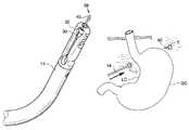
- FIG. 1is a perspective view of the electrosurgical dissector and snare device.
- FIG. 2Ais a perspective view of the jaw tip of the device of FIG. 1
- FIG. 2Bis a longitudinal cross-section view of the jaw tip of FIG. 2 .
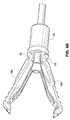
- FIG. 3is a perspective view of the distal end of the device, with the jaw tip removed.
- FIG. 4Ais similar to FIG. 3 but includes the jaw tip.
- FIG. 4Bis a perspective view of the distal end of the device showing the jaws flexed into the opened position.
- FIG. 5Ais similar to FIG. 4 but shows the snare fully extended.
- FIG. 5Bis similar to FIG. 5A but shows the snare partially extended.
- FIG. 5Cis a close-up view of the partially extended snare.
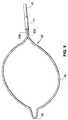
- FIG. 6is a perspective view of the snare removed from the snare guide tube and shaft;
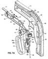
- FIG. 7Ais a partially exploded view of the handle in which one shell section of the handle housing is not shown.
- FIG. 7Bis a side elevation of the contents of the handle without the housing.
- FIG. 8is similar to FIG. 7B but shows one shell section of the housing.
- FIGS. 9A-9Care a sequence of drawings schematically illustrating use of the device for implantation of a gastric banding device.
- the present applicationdescribes a medical instrument having an elongate shaft and a snare extendable from the distal portion of the shaft.
- the instrumentis used to position a band around a stomach in a body cavity.
- the elongate shaftis introduced into the body cavity.
- a distal tip of the snare loopis advanced from the shaft to a first position in which the distal tip is distal to the shaft.
- the distal tipis energized using a source of electrosurgical energy.
- the shaftis advanced in a first direction to form a tunnel through tissue around a portion of the stomach using the energized distal tip.
- the shaftincludes jaws, and the distal tip may be advanced from a distal end of the jaws.
- the jawsmay be dissecting jaws, and the tunnel may be expanded using the dissecting jaws.
- expanding the tunnel using the dissecting jawsis performed during advancement of the shaft to form the tunnel using the energized tip.
- expanding the tunnelincludes, after forming the tunnel, withdrawing the shaft in the second direction while manipulating the jaws to expand the tunnel.
- the snare loopWith the shaft disposed in the tunnel, the snare loop is advanced to a second position in which the snare loop is distal to the shaft. A portion of a gastric banding device is passed through the snare loop. The snare loop is partially withdrawn relative to the shaft to close the snare loop against the banding device. The shaft is withdrawn in a second direction opposite to the first direction to draw a portion of the gastric banding device through the tunnel. The gastric banding device is retained around the stomach.
- FIG. 1shows an embodiment of a combination electrosurgical dissector and snare device 10 .
- Dissector and snare device 10has a handle 12 and an elongate shaft 14 having a pre-curved distal section 15 .
- the shaftis preferably rigid or semi-rigid so as to allow it to approximately retain its shape during use, although in alternative embodiment flexible shafts may be used.
- a jaw tip 16is positioned at the distal end of the shaft 14 .
- the jaw tip 16is a tubular element having integrally formed first and second jaw members 18 a , 18 b extending from a tubular coupling 20 .
- the single piece construction of the jaw tipbiases the jaw members 18 a , 18 b in the closed position shown in FIG. 2A .
- Each jaw memberhas a pair of teeth 19 extending towards the opposed jaw member.
- the jaw members 18 a , 18 bdefine a distal gap or passage 22 at their distal ends.
- the jaw tip 16includes a cylindrical lumen 24 aligned with the passage 22 .
- Walls defining the lumen 24having longitudinally-extending edges 26 between the jaw members 18 a , 18 b .
- the edges 26define a space between the jaw members 18 a , 18 b . Due to the varying contour of the edges 26 , the space has a broad distal section 28 a and a narrow section 28 b proximal to the distal section 28 a.
- a snare guide tube 30extends through the lumen of the shaft 14 .
- a distal element 32is positioned at the tip of the guide tube 30 and has an opening 34 aligned with the lumen of the snare guide tube 30 .
- the distal element 32is a spherical bead, the surface of which, as shown in FIG. 4A , extends into the broad distal section 28 a of the space between the jaw members 18 a , 18 b .
- the opening 34 in the distal element 32is aligned with the distal passage 22 defined by the jaws in the closed position.
- the proximal end of the snare guide tube 30is coupled to a piston 35 disposed within the handle 12 .
- the piston 35is longitudinally moveable within the handle to a retracted position to withdraw the snare guide tube 30 and thus its distal element 32 in a proximal direction.
- the distal elementWhen the distal element is moved proximally, it cams the jaws to the open position shown in FIG. 4B as it moves from within the broad distal section 28 a to the narrow section 28 b of the space defined by the edges 26 .
- the jaw members 18 a , 18 bflex at flex regions 33 when they are moved to the open position.
- the distal elementis returned to a more distal position within the broad section 28 a , it moves out of contact with the edges 26 , allowing the spring bias of the jaw members 18 a , 18 b to return them to the closed position.
- a snare 36is disposed within the snare guide tube 30 .
- the snare 36is formed of a wire strand formed into a loop 38 .
- FIG. 5Ashows the snare 36 in a fully deployed position in which the loop 38 is fully extended from the guide tube 30 .
- a v-shaped tip section 40is positioned at the distal end of the loop 38 .
- the snareis advanceable from the fully retracted position shown in FIG. 4A in which the snare loop is fully contained within the snare guide tube 30 , to a partially extended position shown in FIG. 5B in which the tip section 40 extends from the snare guide tube 30 .
- the snare loopWhen the snare loop is in the partially extended position, the portions of the wire loop just proximal to the “v” may extend in parallel contact with one another as shown in FIG. 5C .
- the snare loopis further advanceable to the fully deployed position shown in FIG. 5A .
- the snare 36is formed of an electrically conductive wire so that the tip can function as an RF dissection wire.
- the snare 36may be conductive only at the tip 40 , with the remainder of the loop 38 covered by insulative material, or the entire loop 40 (including the tip 40 ) may be conductive.
- the snare 36includes two parallel proximal end sections 42 a , 42 b of the snare wire.
- the end sections 42 a , 42 bare connected to a snare conductor 43 by soldering, using a short piece of tubing 47 to cover and complete the joint.
- the snare conductor 43extends through the snare guide tube 30 , around a pin 44 , and is coupled to a slider 46 .
- the slider 46includes first and second pins 48 a , 48 b , each of which is connected to the snare conductor 43 . As shown in FIG.
- each pin 48 a , 48 bare slidably disposed in slots 50 in opposite sides of the handle housing (one side of which is shown).
- a head 52 on the slider 46is slidably positioned within slots 53 parallel to the slots 50 .
- An upper surface of the headincludes a sawtooth pattern of ridges 55 a .
- Corresponding ridges 55 bare formed in the slots 53 such that the ridges 55 a , 55 b engage one another to maintain the longitudinal position of the slider 46 within the slots 53 .
- the snare conductor 43extends from the second pin 48 b of the slider 46 , around another pin 56 and a series of pulleys 58 , 60 , 62 and is coupled to a proximal side of the piston 35 .
- Pulley 58is supported by a bracket 64 mounted to a compression spring 66 .
- the compression spring 66is seated within a slot 68 ( FIG. 7A ) in the handle 12 .
- the snare conductor 43is electrically coupled to an energy source such as a monopolar RF source 45 ( FIG. 1 ).
- FIG. 7Bshows that in the illustrated embodiment, a conductor 59 is coupled to one of the pins 56 with which the snare conductor 43 is in contact, so that the pin 56 electrically couples the snare conductor 43 to conductor 59 .
- a pair of jaw actuation cables 70is connected to the piston 35 .
- the cables 70extend around a pin and are connected to spool 72 connected to a grip 74 .
- the spool 72is pivotally mounted within the handle 12 by a pin 76 .
- a preferred handle housingis comprised of shell halves 78 a , 78 b which, when assembled, leaved an exposed cutout 80 .
- the cutout 80is covered by a cover 82 having flexible end sections 84 that extend into the cutout 80 .
- the cover 82includes a button 86 disposed between the end sections 84 .
- the button 86is coupled to a standoff 87 ( FIG. 7A ) that extends towards the button 86 from the head 52 of slider 46 ( FIG. 8 ).
- the sawtooth ridges 55 b in the handle 12contact the head 52 on opposite sides of the standoff 87 .
- a userwill typically hold the device with his/her palm against the handle 12 , his/her index finger extending through the grip 74 , and his/her thumb on the button 86 .
- the usersqueezes the grip 74 towards the handle 12 , causing the grip 74 and spool 72 to pivot relative to the pin 76 and to thus apply tension to the jaw actuation cables 70 .
- the actuation cables 70pull the piston 35 in a proximal direction and in doing so they withdraw the snare guide tube 30 proximally.
- the distal element 32 on the snare guide tube 30spreads the jaws apart by camming the jaws into the open position by acting on the edges 26 as described above. Releasing the grip 74 causes the jaws to return to the open position under their own spring bias.
- the features for retracting the snare guide tube 30 to open the jaws and for deploying the snareoperate cooperatively to maintain the longitudinal alignment of the snare loop 38 and the snare guide tube 30 .
- the piston 35when the piston 35 is moved proximally to retract the snare guide tube 30 , it pulls the distal end of the snare cable 43 (i.e. the portion anchored to the piston 35 near pulley 62 ) proximally, applying tension to the slider 46 and thus the portion of the snare cable 43 that extends into the snare guide tube 30 , to retract the snare 36 by a corresponding amount.
- the bracket 64 and spring 66act as a tensioning system to aid in maintaining the position of the snare loop 38 relative to the jaws 18 a , 18 b.
- the userpresses button 86 using his or her thumb.
- the button 86presses downwardly against the head 52 of the slider 46 , releasing the engagement between the sawtooth ridges 55 a , 55 b .
- the slider 46is free to slide longitudinally within the handle.
- the useradvances the button 86 to slide the slider 46 in a distal direction, thus pushing the snare loop 38 from the distal end of the snare guide tube 30 .
- the snare loop 38can be advanced whether the jaws are closed or open.
- the jaw tip 16is preferably formed of material that is not electrically conductive so as to prevent conduction of RF energy from the snare to the jaws.
- the usermay advance the snare loop 38 by a first amount to expose only the tip 40 ( FIG. 5B ), or s/he may advance the snare loop 38 by a greater amount to fully deploy the snare ( FIG. 5A ).
- the usercan engage the snare loop 38 in an extended position by releasing pressure against the button 86 , allowing the sawtooth ridges of the head 52 to re-engage with the corresponding ridges in the handle.
- the userapplies downward pressure to the button 86 to disengage the ridges 55 a , 55 b and s/he then retracts the button 86 proximally to return the slider to its original position.
- the device 10is advanced through a single port or laparoscopic access device into the abdominal cavity and advanced towards the stomach.
- the snare loop 38is advanced to the position shown in FIG. 5B , exposing the tip 40 .
- the snare loop 38is energized by activating the RF energy source 45 (e.g. by depressing a foot pedal).
- the tip 40is advanced around the posterior side of the stomach, electrosurgically forming a tunnel T through the fascia, connective tissue and/or other tissue posterior to the stomach as shown in FIG. 9A .
- the usermay begin the electrosurgical step adjacent to the lesser curvature LC of the stomach and continue formation of the tunnel under the stomach to the greater curvature GC, or the electrosurgical step may be at the greater curvature and work towards the lesser curvature.
- the electrosurgically formed tunnel Tis expanded using the dissecting jaws 18 a , 18 b as shown in FIG. 9B .
- This stepmay be performed during the electrosurgical step, with the jaws being opened and closed behind the energized tip 40 as the tip 40 forms the tunnel through the tissue.
- the distal end of the devicemay be retracted back through tunnel and the jaws used at that time (during retraction and/or subsequent re-advancement of the device within the tunnel) to increase the size of the tunnel using known dissection techniques.
- Use of the jaws for dissectioncan involve opening the jaws to separate tissue layers on opposite sides of the jaws
- the curvature of the distal section 15aids in directing the operative tip around the stomach and into a more anterior position ( FIG. 9C ) appropriate for full deployment of the snare for retrieving the gastric band G.
- the snareis moved to the fully deployed position of FIG. 5A , and a portion of a gastric banding device is placed within the loop of the snare.
- the snareis withdrawn somewhat to cinch the loop against the gastric banding device.
- the device 10is withdrawn, passing again around the posterior side of the stomach, thus drawing the engaged end of the gastric banding device with it.
- the banding deviceis closed into a loop and retained in place using known techniques.
- the dissector and snare device 10is removed from the body cavity, leaving the banding device implanted around the stomach.
Landscapes
- Health & Medical Sciences (AREA)
- Life Sciences & Earth Sciences (AREA)
- Surgery (AREA)
- Engineering & Computer Science (AREA)
- Public Health (AREA)
- Animal Behavior & Ethology (AREA)
- Biomedical Technology (AREA)
- Heart & Thoracic Surgery (AREA)
- Veterinary Medicine (AREA)
- General Health & Medical Sciences (AREA)
- Molecular Biology (AREA)
- Nuclear Medicine, Radiotherapy & Molecular Imaging (AREA)
- Medical Informatics (AREA)
- Otolaryngology (AREA)
- Physics & Mathematics (AREA)
- Plasma & Fusion (AREA)
- Pathology (AREA)
- Ophthalmology & Optometry (AREA)
- Child & Adolescent Psychology (AREA)
- Obesity (AREA)
- Nursing (AREA)
- Orthopedic Medicine & Surgery (AREA)
- Vascular Medicine (AREA)
- Surgical Instruments (AREA)
Abstract
Description
Claims (5)
Priority Applications (2)
| Application Number | Priority Date | Filing Date | Title |
|---|---|---|---|
| US12/469,071US8246617B2 (en) | 2007-09-12 | 2009-05-20 | Surgical snare with electrosurgical tip and method of use |
| US13/368,256US20130041372A1 (en) | 2007-09-12 | 2012-02-07 | Surgical Snare with Electrosurgical Tip and Method of Use |
Applications Claiming Priority (3)
| Application Number | Priority Date | Filing Date | Title |
|---|---|---|---|
| US97190007P | 2007-09-12 | 2007-09-12 | |
| US12/209,586US20090157076A1 (en) | 2007-09-12 | 2008-09-12 | Devices and systems for minimally invasive surgical procedures |
| US12/469,071US8246617B2 (en) | 2007-09-12 | 2009-05-20 | Surgical snare with electrosurgical tip and method of use |
Related Parent Applications (1)
| Application Number | Title | Priority Date | Filing Date |
|---|---|---|---|
| US12/209,586Continuation-In-PartUS20090157076A1 (en) | 2007-09-12 | 2008-09-12 | Devices and systems for minimally invasive surgical procedures |
Related Child Applications (1)
| Application Number | Title | Priority Date | Filing Date |
|---|---|---|---|
| US13/368,256ContinuationUS20130041372A1 (en) | 2007-09-12 | 2012-02-07 | Surgical Snare with Electrosurgical Tip and Method of Use |
Publications (2)
| Publication Number | Publication Date |
|---|---|
| US20110082456A1 US20110082456A1 (en) | 2011-04-07 |
| US8246617B2true US8246617B2 (en) | 2012-08-21 |
Family
ID=43823774
Family Applications (2)
| Application Number | Title | Priority Date | Filing Date |
|---|---|---|---|
| US12/469,071Active2029-02-24US8246617B2 (en) | 2007-09-12 | 2009-05-20 | Surgical snare with electrosurgical tip and method of use |
| US13/368,256AbandonedUS20130041372A1 (en) | 2007-09-12 | 2012-02-07 | Surgical Snare with Electrosurgical Tip and Method of Use |
Family Applications After (1)
| Application Number | Title | Priority Date | Filing Date |
|---|---|---|---|
| US13/368,256AbandonedUS20130041372A1 (en) | 2007-09-12 | 2012-02-07 | Surgical Snare with Electrosurgical Tip and Method of Use |
Country Status (1)
| Country | Link |
|---|---|
| US (2) | US8246617B2 (en) |
Cited By (36)
| Publication number | Priority date | Publication date | Assignee | Title |
|---|---|---|---|---|
| US20090157076A1 (en)* | 2007-09-12 | 2009-06-18 | Athas William L | Devices and systems for minimally invasive surgical procedures |
| US9554932B2 (en) | 2013-03-15 | 2017-01-31 | Ez-Off Weight Loss, Llc | System and method for gastric restriction and malabsorption |
| US20170196556A1 (en)* | 2016-01-07 | 2017-07-13 | Covidien Lp | Surgical fastener apparatus |
| US9833350B2 (en) | 2013-03-15 | 2017-12-05 | Ez-Off Weightloss, Llc | Anchorable size-varying gastric balloons for weight loss |
| US10052761B2 (en) | 2015-07-17 | 2018-08-21 | Deka Products Limited Partnership | Robotic surgery system, method, and apparatus |
| US10219799B2 (en) | 2013-08-05 | 2019-03-05 | Endo-Tagss, Llc | Transabdominal gastric device and method |
| US10258372B2 (en) | 2013-08-05 | 2019-04-16 | Endo-Tagss, Llc | Transabdominal gastric surgery system and method |
| US10413374B2 (en) | 2018-02-07 | 2019-09-17 | Distalmotion Sa | Surgical robot systems comprising robotic telemanipulators and integrated laparoscopy |
| US10510447B2 (en) | 2011-07-27 | 2019-12-17 | Ecole Polytechnique Federale De Lausanne (Epfl) | Surgical teleoperated device for remote manipulation |
| US10548680B2 (en) | 2014-12-19 | 2020-02-04 | Distalmotion Sa | Articulated handle for mechanical telemanipulator |
| US10568709B2 (en) | 2015-04-09 | 2020-02-25 | Distalmotion Sa | Mechanical teleoperated device for remote manipulation |
| US10646294B2 (en) | 2014-12-19 | 2020-05-12 | Distalmotion Sa | Reusable surgical instrument for minimally invasive procedures |
| US10786272B2 (en) | 2015-08-28 | 2020-09-29 | Distalmotion Sa | Surgical instrument with increased actuation force |
| US10813781B2 (en) | 2016-10-04 | 2020-10-27 | Ez-Off Weight Loss, Llc | Sleeve-anchorable gastric balloon for weight loss |
| US10864052B2 (en) | 2014-12-19 | 2020-12-15 | Distalmotion Sa | Surgical instrument with articulated end-effector |
| US10864049B2 (en) | 2014-12-19 | 2020-12-15 | Distalmotion Sa | Docking system for mechanical telemanipulator |
| US11039820B2 (en) | 2014-12-19 | 2021-06-22 | Distalmotion Sa | Sterile interface for articulated surgical instruments |
| US11058503B2 (en) | 2017-05-11 | 2021-07-13 | Distalmotion Sa | Translational instrument interface for surgical robot and surgical robot systems comprising the same |
| US11076922B2 (en) | 2010-10-11 | 2021-08-03 | Ecole Polytechnique Federale De Lausanne (Epfl) | Mechanical manipulator for surgical instruments |
| US11504197B1 (en) | 2021-03-31 | 2022-11-22 | Moon Surgical Sas | Co-manipulation surgical system having multiple operational modes for use with surgical instruments for performing laparoscopic surgery |
| US11812938B2 (en) | 2021-03-31 | 2023-11-14 | Moon Surgical Sas | Co-manipulation surgical system having a coupling mechanism removeably attachable to surgical instruments |
| US11819302B2 (en) | 2021-03-31 | 2023-11-21 | Moon Surgical Sas | Co-manipulation surgical system having user guided stage control |
| US11832909B2 (en) | 2021-03-31 | 2023-12-05 | Moon Surgical Sas | Co-manipulation surgical system having actuatable setup joints |
| US11832910B1 (en) | 2023-01-09 | 2023-12-05 | Moon Surgical Sas | Co-manipulation surgical system having adaptive gravity compensation |
| US11844585B1 (en) | 2023-02-10 | 2023-12-19 | Distalmotion Sa | Surgical robotics systems and devices having a sterile restart, and methods thereof |
| US11844583B2 (en) | 2021-03-31 | 2023-12-19 | Moon Surgical Sas | Co-manipulation surgical system having an instrument centering mode for automatic scope movements |
| US11980412B2 (en) | 2020-09-15 | 2024-05-14 | Boston Scientific Medical Device Limited | Elongated medical sheath |
| US11986165B1 (en) | 2023-01-09 | 2024-05-21 | Moon Surgical Sas | Co-manipulation surgical system for use with surgical instruments for performing laparoscopic surgery while estimating hold force |
| US12042241B2 (en) | 2021-03-31 | 2024-07-23 | Moon Surgical Sas | Co-manipulation surgical system having automated preset robot arm configurations |
| US12114945B2 (en) | 2021-09-13 | 2024-10-15 | Distalmotion Sa | Instruments for surgical robotic system and interfaces for the same |
| US12167900B2 (en) | 2021-03-31 | 2024-12-17 | Moon Surgical Sas | Co-manipulation surgical system having automated preset robot arm configurations |
| US12178418B2 (en) | 2021-03-31 | 2024-12-31 | Moon Surgical Sas | Co-manipulation surgical system having a coupling mechanism removeably attachable to surgical instruments |
| US12329481B2 (en) | 2014-02-03 | 2025-06-17 | Distalmotion Sa | Mechanical teleoperated device comprising an interchangeable distal instrument |
| US12370001B2 (en) | 2023-01-09 | 2025-07-29 | Moon Surgical Sas | Co-manipulation surgical system having automated user override detection |
| US12376927B2 (en) | 2018-02-07 | 2025-08-05 | Distalmotion Sa | Surgical robot systems comprising robotic telemanipulators and integrated laparoscopy |
| US12402960B2 (en) | 2010-10-11 | 2025-09-02 | Ecole Polytechnique Federale De Lausanne (Epfl) | Mechanical manipulator for surgical instruments |
Families Citing this family (11)
| Publication number | Priority date | Publication date | Assignee | Title |
|---|---|---|---|---|
| US8308682B2 (en) | 2003-07-18 | 2012-11-13 | Broncus Medical Inc. | Devices for maintaining patency of surgically created channels in tissue |
| US8409167B2 (en) | 2004-07-19 | 2013-04-02 | Broncus Medical Inc | Devices for delivering substances through an extra-anatomic opening created in an airway |
| US8512371B2 (en)* | 2009-10-06 | 2013-08-20 | Covidien Lp | Jaw, blade and gap manufacturing for surgical instruments with small jaws |
| US8343045B2 (en)* | 2010-04-05 | 2013-01-01 | Intuitive Surgical Operations, Inc. | Curved cannula |
| US9345532B2 (en) | 2011-05-13 | 2016-05-24 | Broncus Medical Inc. | Methods and devices for ablation of tissue |
| US8709034B2 (en) | 2011-05-13 | 2014-04-29 | Broncus Medical Inc. | Methods and devices for diagnosing, monitoring, or treating medical conditions through an opening through an airway wall |
| WO2013078235A1 (en) | 2011-11-23 | 2013-05-30 | Broncus Medical Inc | Methods and devices for diagnosing, monitoring, or treating medical conditions through an opening through an airway wall |
| EP3441023B1 (en)* | 2013-10-10 | 2021-04-07 | Gyrus ACMI, Inc. (D.B.A. Olympus Surgical Technologies America) | Laparoscopic forceps assembly |
| US10080584B2 (en)* | 2015-12-03 | 2018-09-25 | Timothy L. Miller | System and method for receiving tube forceps for use in body piercings |
| GB2569177B (en)* | 2017-12-08 | 2019-12-04 | Surgerytech Aps | Endoscope system |
| USD918387S1 (en) | 2019-03-05 | 2021-05-04 | Surgery-Tech Aps | Medical device |
Citations (12)
| Publication number | Priority date | Publication date | Assignee | Title |
|---|---|---|---|---|
| US5226429A (en)* | 1991-06-20 | 1993-07-13 | Inamed Development Co. | Laparoscopic gastric band and method |
| US5304183A (en) | 1992-03-23 | 1994-04-19 | Laparomed Corporation | Tethered clamp retractor |
| US5697931A (en) | 1995-06-14 | 1997-12-16 | Incont, Inc. | Apparatus and method for laparoscopic urethopexy |
| US6066090A (en) | 1997-06-19 | 2000-05-23 | Yoon; Inbae | Branched endoscope system |
| US20010049497A1 (en) | 2000-03-24 | 2001-12-06 | Kalloo Anthony Nicolas | Methods and devices for diagnostic and therapeutic interventions in the peritoneal cavity |
| US20030212429A1 (en) | 2002-03-05 | 2003-11-13 | Martin Keegan | Embolic protection system |
| EP1586275A2 (en) | 2004-04-13 | 2005-10-19 | Olympus Corporation | Endoscope therapeutic device |
| WO2006110275A2 (en) | 2005-04-11 | 2006-10-19 | Usgi Medical Inc. | Methods and apparatus for off-axis visualization |
| US20070038230A1 (en) | 2005-08-11 | 2007-02-15 | Arthrotek, Inc. | Steerable suture passing device |
| US20070288035A1 (en) | 2006-06-09 | 2007-12-13 | Olympus Medical Systems Corp. | Endoscopic treatment instrument and endoscope system |
| US20080009854A1 (en)* | 2006-07-06 | 2008-01-10 | Yates Leroy L | Resecting device |
| WO2009035650A2 (en) | 2007-09-12 | 2009-03-19 | Synecor, Llc. | Device for minimally invasive surgical procedures |
Family Cites Families (2)
| Publication number | Priority date | Publication date | Assignee | Title |
|---|---|---|---|---|
| US6616654B2 (en)* | 2001-07-27 | 2003-09-09 | Starion Instruments Corporation | Polypectomy device and method |
| US20050228403A1 (en)* | 2004-03-31 | 2005-10-13 | Manoa Medical, Inc., A Delaware Corporation | Tissue cutting devices and methods |
- 2009
- 2009-05-20USUS12/469,071patent/US8246617B2/enactiveActive
- 2012
- 2012-02-07USUS13/368,256patent/US20130041372A1/ennot_activeAbandoned
Patent Citations (13)
| Publication number | Priority date | Publication date | Assignee | Title |
|---|---|---|---|---|
| US5226429A (en)* | 1991-06-20 | 1993-07-13 | Inamed Development Co. | Laparoscopic gastric band and method |
| US5304183A (en) | 1992-03-23 | 1994-04-19 | Laparomed Corporation | Tethered clamp retractor |
| US5697931A (en) | 1995-06-14 | 1997-12-16 | Incont, Inc. | Apparatus and method for laparoscopic urethopexy |
| US6066090A (en) | 1997-06-19 | 2000-05-23 | Yoon; Inbae | Branched endoscope system |
| US20010049497A1 (en) | 2000-03-24 | 2001-12-06 | Kalloo Anthony Nicolas | Methods and devices for diagnostic and therapeutic interventions in the peritoneal cavity |
| US20030212429A1 (en) | 2002-03-05 | 2003-11-13 | Martin Keegan | Embolic protection system |
| EP1586275A2 (en) | 2004-04-13 | 2005-10-19 | Olympus Corporation | Endoscope therapeutic device |
| WO2006110275A2 (en) | 2005-04-11 | 2006-10-19 | Usgi Medical Inc. | Methods and apparatus for off-axis visualization |
| US20070038230A1 (en) | 2005-08-11 | 2007-02-15 | Arthrotek, Inc. | Steerable suture passing device |
| US20070288035A1 (en) | 2006-06-09 | 2007-12-13 | Olympus Medical Systems Corp. | Endoscopic treatment instrument and endoscope system |
| US20080009854A1 (en)* | 2006-07-06 | 2008-01-10 | Yates Leroy L | Resecting device |
| WO2009035650A2 (en) | 2007-09-12 | 2009-03-19 | Synecor, Llc. | Device for minimally invasive surgical procedures |
| US20090157076A1 (en) | 2007-09-12 | 2009-06-18 | Athas William L | Devices and systems for minimally invasive surgical procedures |
Non-Patent Citations (1)
| Title |
|---|
| International Search Report for PCT/US2008/010640, mailed May 19, 2009, 1 page.* |
Cited By (63)
| Publication number | Priority date | Publication date | Assignee | Title |
|---|---|---|---|---|
| US20090157076A1 (en)* | 2007-09-12 | 2009-06-18 | Athas William L | Devices and systems for minimally invasive surgical procedures |
| US11076922B2 (en) | 2010-10-11 | 2021-08-03 | Ecole Polytechnique Federale De Lausanne (Epfl) | Mechanical manipulator for surgical instruments |
| US12402960B2 (en) | 2010-10-11 | 2025-09-02 | Ecole Polytechnique Federale De Lausanne (Epfl) | Mechanical manipulator for surgical instruments |
| US10510447B2 (en) | 2011-07-27 | 2019-12-17 | Ecole Polytechnique Federale De Lausanne (Epfl) | Surgical teleoperated device for remote manipulation |
| US11200980B2 (en) | 2011-07-27 | 2021-12-14 | Ecole Polytechnique Federale De Lausanne (Epfl) | Surgical teleoperated device for remote manipulation |
| US9554932B2 (en) | 2013-03-15 | 2017-01-31 | Ez-Off Weight Loss, Llc | System and method for gastric restriction and malabsorption |
| US9833350B2 (en) | 2013-03-15 | 2017-12-05 | Ez-Off Weightloss, Llc | Anchorable size-varying gastric balloons for weight loss |
| US10219799B2 (en) | 2013-08-05 | 2019-03-05 | Endo-Tagss, Llc | Transabdominal gastric device and method |
| US10258372B2 (en) | 2013-08-05 | 2019-04-16 | Endo-Tagss, Llc | Transabdominal gastric surgery system and method |
| US12329481B2 (en) | 2014-02-03 | 2025-06-17 | Distalmotion Sa | Mechanical teleoperated device comprising an interchangeable distal instrument |
| US10548680B2 (en) | 2014-12-19 | 2020-02-04 | Distalmotion Sa | Articulated handle for mechanical telemanipulator |
| US12262880B2 (en) | 2014-12-19 | 2025-04-01 | Distalmotion Sa | Sterile interface for articulated surgical instruments |
| US11571195B2 (en) | 2014-12-19 | 2023-02-07 | Distalmotion Sa | Sterile interface for articulated surgical instruments |
| US12262969B2 (en) | 2014-12-19 | 2025-04-01 | Distalmotion Sa | Reusable surgical instrument for minimally invasive procedures |
| US10864052B2 (en) | 2014-12-19 | 2020-12-15 | Distalmotion Sa | Surgical instrument with articulated end-effector |
| US10864049B2 (en) | 2014-12-19 | 2020-12-15 | Distalmotion Sa | Docking system for mechanical telemanipulator |
| US11039820B2 (en) | 2014-12-19 | 2021-06-22 | Distalmotion Sa | Sterile interface for articulated surgical instruments |
| US10646294B2 (en) | 2014-12-19 | 2020-05-12 | Distalmotion Sa | Reusable surgical instrument for minimally invasive procedures |
| US11478315B2 (en) | 2014-12-19 | 2022-10-25 | Distalmotion Sa | Reusable surgical instrument for minimally invasive procedures |
| US10568709B2 (en) | 2015-04-09 | 2020-02-25 | Distalmotion Sa | Mechanical teleoperated device for remote manipulation |
| US11117258B2 (en) | 2015-07-17 | 2021-09-14 | Deka Products Limited Partnership | Robotic surgery system, method, and apparatus |
| US11981030B2 (en) | 2015-07-17 | 2024-05-14 | Deka Products Limited Partnership | Robotic surgery system, method, and apparatus |
| US12358133B2 (en) | 2015-07-17 | 2025-07-15 | Deka Products Limited Partneship | Robotic surgery system, method, and apparatus |
| US10052761B2 (en) | 2015-07-17 | 2018-08-21 | Deka Products Limited Partnership | Robotic surgery system, method, and apparatus |
| US11337716B2 (en) | 2015-08-28 | 2022-05-24 | Distalmotion Sa | Surgical instrument with increased actuation force |
| US11944337B2 (en) | 2015-08-28 | 2024-04-02 | Distalmotion Sa | Surgical instrument with increased actuation force |
| US10786272B2 (en) | 2015-08-28 | 2020-09-29 | Distalmotion Sa | Surgical instrument with increased actuation force |
| US20170196556A1 (en)* | 2016-01-07 | 2017-07-13 | Covidien Lp | Surgical fastener apparatus |
| US10813781B2 (en) | 2016-10-04 | 2020-10-27 | Ez-Off Weight Loss, Llc | Sleeve-anchorable gastric balloon for weight loss |
| US12295688B2 (en) | 2017-05-11 | 2025-05-13 | Distalmotion Sa | Translational instrument interface for surgical robot and surgical robot systems comprising the same |
| US12262968B2 (en) | 2017-05-11 | 2025-04-01 | Distalmotion Sa | Translational instrument interface for surgical robot and surgical robot systems comprising the same |
| US11058503B2 (en) | 2017-05-11 | 2021-07-13 | Distalmotion Sa | Translational instrument interface for surgical robot and surgical robot systems comprising the same |
| US12376927B2 (en) | 2018-02-07 | 2025-08-05 | Distalmotion Sa | Surgical robot systems comprising robotic telemanipulators and integrated laparoscopy |
| US12290328B2 (en) | 2018-02-07 | 2025-05-06 | Distalmotion Sa | Surgical robot systems comprising robotic telemanipulators and integrated laparoscopy |
| US11510745B2 (en) | 2018-02-07 | 2022-11-29 | Distalmotion Sa | Surgical robot systems comprising robotic telemanipulators and integrated laparoscopy |
| US10413374B2 (en) | 2018-02-07 | 2019-09-17 | Distalmotion Sa | Surgical robot systems comprising robotic telemanipulators and integrated laparoscopy |
| US12161438B2 (en) | 2018-02-07 | 2024-12-10 | Distalmotion Sa | Surgical robot systems comprising robotic telemanipulators and integrated laparoscopy |
| US11980412B2 (en) | 2020-09-15 | 2024-05-14 | Boston Scientific Medical Device Limited | Elongated medical sheath |
| US11819302B2 (en) | 2021-03-31 | 2023-11-21 | Moon Surgical Sas | Co-manipulation surgical system having user guided stage control |
| US12161432B2 (en) | 2021-03-31 | 2024-12-10 | Moon Surgical Sas | Co-manipulation surgical system having a robot arm removeably attachable to surgical instruments for performing laparoscopic surgery |
| US11504197B1 (en) | 2021-03-31 | 2022-11-22 | Moon Surgical Sas | Co-manipulation surgical system having multiple operational modes for use with surgical instruments for performing laparoscopic surgery |
| US12011149B2 (en) | 2021-03-31 | 2024-06-18 | Moon Surgical Sas | Co-manipulation surgical system for bedside robotic laparoscopic surgery using surgical instruments |
| US12042241B2 (en) | 2021-03-31 | 2024-07-23 | Moon Surgical Sas | Co-manipulation surgical system having automated preset robot arm configurations |
| US12396711B2 (en) | 2021-03-31 | 2025-08-26 | Moon Surgical Sas | Co-manipulation surgical system having multiple operational modes for use with surgical instruments for performing surgery |
| US11622826B2 (en) | 2021-03-31 | 2023-04-11 | Moon Surgical Sas | Co-manipulation surgical system for use with surgical instruments for performing laparoscopic surgery while compensating for external forces |
| US11812938B2 (en) | 2021-03-31 | 2023-11-14 | Moon Surgical Sas | Co-manipulation surgical system having a coupling mechanism removeably attachable to surgical instruments |
| US11844583B2 (en) | 2021-03-31 | 2023-12-19 | Moon Surgical Sas | Co-manipulation surgical system having an instrument centering mode for automatic scope movements |
| US11786323B2 (en) | 2021-03-31 | 2023-10-17 | Moon Surgical Sas | Self-calibrating co-manipulation surgical system for use with surgical instrument for performing laparoscopic surgery |
| US12167900B2 (en) | 2021-03-31 | 2024-12-17 | Moon Surgical Sas | Co-manipulation surgical system having automated preset robot arm configurations |
| US12178418B2 (en) | 2021-03-31 | 2024-12-31 | Moon Surgical Sas | Co-manipulation surgical system having a coupling mechanism removeably attachable to surgical instruments |
| US11737840B2 (en) | 2021-03-31 | 2023-08-29 | Moon Surgical Sas | Co-manipulation surgical system having a robot arm removeably attachable to surgical instruments for performing laparoscopic surgery |
| US11980431B2 (en) | 2021-03-31 | 2024-05-14 | Moon Surgical Sas | Co-manipulation surgical system for use with surgical instruments having a virtual map display to facilitate setup |
| US12349995B2 (en) | 2021-03-31 | 2025-07-08 | Moon Surgical Sas | Co-manipulation surgical systems having optical sensors for generating graphical displays |
| US11832909B2 (en) | 2021-03-31 | 2023-12-05 | Moon Surgical Sas | Co-manipulation surgical system having actuatable setup joints |
| US12114945B2 (en) | 2021-09-13 | 2024-10-15 | Distalmotion Sa | Instruments for surgical robotic system and interfaces for the same |
| US11839442B1 (en) | 2023-01-09 | 2023-12-12 | Moon Surgical Sas | Co-manipulation surgical system for use with surgical instruments for performing laparoscopic surgery while estimating hold force |
| US11832910B1 (en) | 2023-01-09 | 2023-12-05 | Moon Surgical Sas | Co-manipulation surgical system having adaptive gravity compensation |
| US12370001B2 (en) | 2023-01-09 | 2025-07-29 | Moon Surgical Sas | Co-manipulation surgical system having automated user override detection |
| US11986165B1 (en) | 2023-01-09 | 2024-05-21 | Moon Surgical Sas | Co-manipulation surgical system for use with surgical instruments for performing laparoscopic surgery while estimating hold force |
| US12349998B2 (en) | 2023-02-10 | 2025-07-08 | Distalmotion Sa | Surgical robotics systems and devices having a sterile restart, and methods thereof |
| US11844585B1 (en) | 2023-02-10 | 2023-12-19 | Distalmotion Sa | Surgical robotics systems and devices having a sterile restart, and methods thereof |
| US12089908B2 (en) | 2023-02-10 | 2024-09-17 | Distalmotion Sa | Surgical robotics systems and devices having a sterile restart, and methods thereof |
| US12082899B2 (en) | 2023-02-10 | 2024-09-10 | Distalmotion Sa | Surgical robotics systems and devices having a sterile restart, and methods thereof |
Also Published As
| Publication number | Publication date |
|---|---|
| US20110082456A1 (en) | 2011-04-07 |
| US20130041372A1 (en) | 2013-02-14 |
Similar Documents
| Publication | Publication Date | Title |
|---|---|---|
| US8246617B2 (en) | Surgical snare with electrosurgical tip and method of use | |
| US8715281B2 (en) | Treatment device for endoscope | |
| EP1849424B1 (en) | Apparatus for performing an endoscopic mucosal resection | |
| US7981127B2 (en) | Treatment sheath for endoscopic blood vessel harvesting | |
| JP5345297B2 (en) | Flexible endoscope safety needle | |
| US20060064113A1 (en) | Endoscopic mucosal resection method and associated instrument | |
| US20060211916A1 (en) | Living tissue harvesting apparatus | |
| US20070270643A1 (en) | Lumen stabilizer for endoscopic mucosal resection | |
| JP2008206972A (en) | Suture tool | |
| KR20100021968A (en) | Mis electrosurgical handpiece | |
| EP2258272A1 (en) | Apparatus for deploying a cutting element during an endoscopic mucosal resection | |
| US20210137514A1 (en) | Repair device for deploying anchors into tissue | |
| EP3886729A1 (en) | Passing tension member around tissue mass | |
| US20250195130A1 (en) | Lesion resection method | |
| US12232720B2 (en) | Systems for soft tissue repair | |
| JPH10216148A (en) | Clamp device having snare | |
| JPH10155799A (en) | Organ lifting device | |
| US20220133290A1 (en) | Endoscopic treatment device, and usage method thereof | |
| KR20250112823A (en) | Removable over-the-scope clip | |
| WO2019202764A1 (en) | Treatment tool | |
| JPH09168546A (en) | High frequency surgical incision and excision instrument |
Legal Events
| Date | Code | Title | Description |
|---|---|---|---|
| AS | Assignment | Owner name:SYNECOR LLC, NORTH CAROLINA Free format text:ASSIGNMENT OF ASSIGNORS INTEREST;ASSIGNORS:WELT, ROBERT E.;ATHAS, WILLIAM L.;MILLER, THOMAS B.;REEL/FRAME:022713/0607 Effective date:20090520 | |
| AS | Assignment | Owner name:TRANSENTERIX, INC., NORTH CAROLINA Free format text:ASSIGNMENT OF ASSIGNORS INTEREST;ASSIGNOR:SYNECOR LLC;REEL/FRAME:024635/0483 Effective date:20090629 | |
| STCF | Information on status: patent grant | Free format text:PATENTED CASE | |
| AS | Assignment | Owner name:TRANSENTERIX SURGICAL, INC., NORTH CAROLINA Free format text:CHANGE OF NAME;ASSIGNOR:TRANSENTERIX, INC.;REEL/FRAME:031771/0224 Effective date:20131127 | |
| FPAY | Fee payment | Year of fee payment:4 | |
| AS | Assignment | Owner name:INNOVATUS LIFE SCIENCES LENDING FUND I, LP, AS COL Free format text:SECURITY INTEREST;ASSIGNOR:TRANSENTERIX SURGICAL, INC.;REEL/FRAME:042483/0895 Effective date:20170523 Owner name:INNOVATUS LIFE SCIENCES LENDING FUND I, LP, AS COLLATERAL AGENT, NEW YORK Free format text:SECURITY INTEREST;ASSIGNOR:TRANSENTERIX SURGICAL, INC.;REEL/FRAME:042483/0895 Effective date:20170523 | |
| AS | Assignment | Owner name:TRANSENTERIX SURGICAL, INC., NORTH CAROLINA Free format text:RELEASE BY SECURED PARTY;ASSIGNOR:INNOVATUS LIFE SCIENCES LENDING FUND I, LP;REEL/FRAME:045892/0868 Effective date:20180523 | |
| MAFP | Maintenance fee payment | Free format text:PAYMENT OF MAINTENANCE FEE, 8TH YR, SMALL ENTITY (ORIGINAL EVENT CODE: M2552); ENTITY STATUS OF PATENT OWNER: SMALL ENTITY Year of fee payment:8 | |
| MAFP | Maintenance fee payment | Free format text:PAYMENT OF MAINTENANCE FEE, 12TH YR, SMALL ENTITY (ORIGINAL EVENT CODE: M2553); ENTITY STATUS OF PATENT OWNER: SMALL ENTITY Year of fee payment:12 | |
| AS | Assignment | Owner name:ASENSUS SURGICAL US, INC., NORTH CAROLINA Free format text:CHANGE OF NAME;ASSIGNOR:TRANSENTERIX SURGICAL, INC.;REEL/FRAME:066960/0293 Effective date:20210225 | |
| AS | Assignment | Owner name:KARL STORZ SE & CO. KG, CALIFORNIA Free format text:SECURITY INTEREST;ASSIGNORS:ASENSUS SURGICAL, INC.;ASENSUS SURGICAL US, INC.;ASENSUS SURGICAL EUROPE S.A R.L.;AND OTHERS;REEL/FRAME:069795/0381 Effective date:20240403 |