US8246142B2 - Rotating printhead maintenance facility with symmetrical chassis - Google Patents
Rotating printhead maintenance facility with symmetrical chassisDownload PDFInfo
- Publication number
- US8246142B2 US8246142B2US12/014,777US1477708AUS8246142B2US 8246142 B2US8246142 B2US 8246142B2US 1477708 AUS1477708 AUS 1477708AUS 8246142 B2US8246142 B2US 8246142B2
- Authority
- US
- United States
- Prior art keywords
- printhead
- maintenance
- chassis
- carousel
- elongate
- Prior art date
- Legal status (The legal status is an assumption and is not a legal conclusion. Google has not performed a legal analysis and makes no representation as to the accuracy of the status listed.)
- Expired - Fee Related, expires
Links
- 238000012423maintenanceMethods0.000titleclaimsabstractdescription140
- 238000007639printingMethods0.000claimsabstractdescription21
- 239000000758substrateSubstances0.000claimsabstractdescription15
- 239000011148porous materialSubstances0.000claimsdescription21
- 239000012530fluidSubstances0.000claimsdescription13
- 238000004891communicationMethods0.000claimsdescription9
- 238000002347injectionMethods0.000claimsdescription9
- 239000007924injectionSubstances0.000claimsdescription9
- 229920000642polymerPolymers0.000claimsdescription9
- 230000015572biosynthetic processEffects0.000claimsdescription7
- 238000005755formation reactionMethods0.000claimsdescription7
- 239000002699waste materialSubstances0.000claimsdescription6
- 238000004140cleaningMethods0.000description31
- 238000000465mouldingMethods0.000description29
- 229920000106Liquid crystal polymerPolymers0.000description20
- 239000004977Liquid-crystal polymers (LCPs)Substances0.000description20
- 238000004519manufacturing processMethods0.000description20
- 239000000356contaminantSubstances0.000description19
- 239000004033plasticSubstances0.000description19
- 229920003023plasticPolymers0.000description19
- 230000002745absorbentEffects0.000description18
- 239000002250absorbentSubstances0.000description18
- 230000037452primingEffects0.000description18
- 238000002955isolationMethods0.000description16
- 239000000463materialSubstances0.000description11
- 238000000034methodMethods0.000description11
- 239000000428dustSubstances0.000description10
- 238000013461designMethods0.000description7
- 230000007246mechanismEffects0.000description7
- 239000011324beadSubstances0.000description5
- 230000008878couplingEffects0.000description5
- 238000010168coupling processMethods0.000description5
- 238000005859coupling reactionMethods0.000description5
- 239000013536elastomeric materialSubstances0.000description5
- 230000001681protective effectEffects0.000description5
- 239000007921spraySubstances0.000description5
- 239000008393encapsulating agentSubstances0.000description4
- 238000001746injection mouldingMethods0.000description4
- 238000002156mixingMethods0.000description4
- 238000006424Flood reactionMethods0.000description3
- XUIMIQQOPSSXEZ-UHFFFAOYSA-NSiliconChemical compound[Si]XUIMIQQOPSSXEZ-UHFFFAOYSA-N0.000description3
- 238000006073displacement reactionMethods0.000description3
- 238000001035dryingMethods0.000description3
- 229910052751metalInorganic materials0.000description3
- 239000002184metalSubstances0.000description3
- 230000035939shockEffects0.000description3
- 229910052710siliconInorganic materials0.000description3
- 239000010703siliconSubstances0.000description3
- 239000000853adhesiveSubstances0.000description2
- 230000001070adhesive effectEffects0.000description2
- 230000000712assemblyEffects0.000description2
- 238000000429assemblyMethods0.000description2
- 230000008901benefitEffects0.000description2
- 238000001125extrusionMethods0.000description2
- 238000010304firingMethods0.000description2
- 239000002783friction materialSubstances0.000description2
- 238000003754machiningMethods0.000description2
- 238000012986modificationMethods0.000description2
- 230000004048modificationEffects0.000description2
- 230000008569processEffects0.000description2
- 238000010926purgeMethods0.000description2
- 230000009467reductionEffects0.000description2
- 230000000717retained effectEffects0.000description2
- 230000003746surface roughnessEffects0.000description2
- 238000011144upstream manufacturingMethods0.000description2
- DTMRKGRREZAYAP-UHFFFAOYSA-N1,2,3,4-tetrachloro-5-(2,3,4,5-tetrachlorophenyl)benzeneChemical compoundClC1=C(Cl)C(Cl)=CC(C=2C(=C(Cl)C(Cl)=C(Cl)C=2)Cl)=C1ClDTMRKGRREZAYAP-UHFFFAOYSA-N0.000description1
- 239000004593EpoxySubstances0.000description1
- 229920001410MicrofiberPolymers0.000description1
- 230000009471actionEffects0.000description1
- 239000000956alloySubstances0.000description1
- 229910045601alloyInorganic materials0.000description1
- 239000004411aluminiumSubstances0.000description1
- 229910052782aluminiumInorganic materials0.000description1
- XAGFODPZIPBFFR-UHFFFAOYSA-NaluminiumChemical compound[Al]XAGFODPZIPBFFR-UHFFFAOYSA-N0.000description1
- 230000008859changeEffects0.000description1
- 230000000295complement effectEffects0.000description1
- 230000006835compressionEffects0.000description1
- 238000007906compressionMethods0.000description1
- 238000011109contaminationMethods0.000description1
- 230000003111delayed effectEffects0.000description1
- 238000005538encapsulationMethods0.000description1
- 238000005516engineering processMethods0.000description1
- 239000000835fiberSubstances0.000description1
- 239000006260foamSubstances0.000description1
- 229920001903high density polyethylenePolymers0.000description1
- 239000004700high-density polyethyleneSubstances0.000description1
- 238000007373indentationMethods0.000description1
- 238000003780insertionMethods0.000description1
- 230000037431insertionEffects0.000description1
- 238000009434installationMethods0.000description1
- 239000007788liquidSubstances0.000description1
- 239000003658microfiberSubstances0.000description1
- 230000002093peripheral effectEffects0.000description1
- 239000002861polymer materialSubstances0.000description1
- 239000000843powderSubstances0.000description1
- 238000002360preparation methodMethods0.000description1
- 238000004064recyclingMethods0.000description1
- 239000012858resilient materialSubstances0.000description1
- 238000007789sealingMethods0.000description1
- 239000007787solidSubstances0.000description1
- 239000002904solventSubstances0.000description1
- 238000004381surface treatmentMethods0.000description1
- 239000004094surface-active agentSubstances0.000description1
- 230000001360synchronised effectEffects0.000description1
- 238000012546transferMethods0.000description1
Images


Classifications
- B—PERFORMING OPERATIONS; TRANSPORTING
- B41—PRINTING; LINING MACHINES; TYPEWRITERS; STAMPS
- B41J—TYPEWRITERS; SELECTIVE PRINTING MECHANISMS, i.e. MECHANISMS PRINTING OTHERWISE THAN FROM A FORME; CORRECTION OF TYPOGRAPHICAL ERRORS
- B41J2/00—Typewriters or selective printing mechanisms characterised by the printing or marking process for which they are designed
- B41J2/005—Typewriters or selective printing mechanisms characterised by the printing or marking process for which they are designed characterised by bringing liquid or particles selectively into contact with a printing material
- B41J2/01—Ink jet
- B41J2/135—Nozzles
- B41J2/165—Prevention or detection of nozzle clogging, e.g. cleaning, capping or moistening for nozzles
- B41J2/16517—Cleaning of print head nozzles
- B41J2/16535—Cleaning of print head nozzles using wiping constructions
- B41J2/16544—Constructions for the positioning of wipers
- B41J2/16547—Constructions for the positioning of wipers the wipers and caps or spittoons being on the same movable support
- B—PERFORMING OPERATIONS; TRANSPORTING
- B41—PRINTING; LINING MACHINES; TYPEWRITERS; STAMPS
- B41J—TYPEWRITERS; SELECTIVE PRINTING MECHANISMS, i.e. MECHANISMS PRINTING OTHERWISE THAN FROM A FORME; CORRECTION OF TYPOGRAPHICAL ERRORS
- B41J2/00—Typewriters or selective printing mechanisms characterised by the printing or marking process for which they are designed
- B41J2/005—Typewriters or selective printing mechanisms characterised by the printing or marking process for which they are designed characterised by bringing liquid or particles selectively into contact with a printing material
- B41J2/01—Ink jet
- B41J2/135—Nozzles
- B41J2/165—Prevention or detection of nozzle clogging, e.g. cleaning, capping or moistening for nozzles
- B41J2/16517—Cleaning of print head nozzles
- B41J2/16535—Cleaning of print head nozzles using wiping constructions
- B41J2/16541—Means to remove deposits from wipers or scrapers
- B—PERFORMING OPERATIONS; TRANSPORTING
- B41—PRINTING; LINING MACHINES; TYPEWRITERS; STAMPS
- B41J—TYPEWRITERS; SELECTIVE PRINTING MECHANISMS, i.e. MECHANISMS PRINTING OTHERWISE THAN FROM A FORME; CORRECTION OF TYPOGRAPHICAL ERRORS
- B41J2/00—Typewriters or selective printing mechanisms characterised by the printing or marking process for which they are designed
- B41J2/005—Typewriters or selective printing mechanisms characterised by the printing or marking process for which they are designed characterised by bringing liquid or particles selectively into contact with a printing material
- B41J2/01—Ink jet
- B41J2/135—Nozzles
- B41J2/165—Prevention or detection of nozzle clogging, e.g. cleaning, capping or moistening for nozzles
- B41J2/16585—Prevention or detection of nozzle clogging, e.g. cleaning, capping or moistening for nozzles for paper-width or non-reciprocating print heads
Definitions
- the present inventionrelates to be field of printers and in particular maintenance facilities for inkjet printheads.
- Wiping the nozzle face of a printheadis an effective way of removing paper dust, ink floods, dried ink or other contaminants.
- pagewidth printheadsare difficult wipe. While pagewidth printers with nozzle face wipers exist, the wiping mechanism is relatively slow and or complicated.
- Currently available pagewidth printheadshave several printhead integrated circuits spaced apart from the cover in the media feed direction. It is impractical for a single wiper to clean all the printhead integrated circuits, so each printhead integrated circuit is wiped individually. Furthermore the wipers move transverse to the media feed direction. This is to avoid colour mixing between the nozzles of different colour but rows of nozzles for each colour extend across the printhead ICs in a direction transverse to the media feed direction.
- Wiping along the rows of nozzlesminimises the risk of contaminating ink in one nozzle with ink of the different colour.
- the wipermust travel the entire length to clean all the nozzles.
- the mechanism that actuates the separate wipers for each printheadis complex, occupying a relatively large space and consuming a significant amount of time during each maintenance cycle.
- the present inventionprovides a maintenance facility for an ink jet printer having a pagewidth printhead and a media path for feeding sheets of media substrate in a media feed direction, the pagewidth printhead having an elongate array of nozzles extending the printing width of the media substrate, the maintenance facility comprising:
- an elongate chassisfor mounting in the printer such that it can rotate about its longitudinal axis
- the elongate chassisis symmetrical about at least one plane extending through the longitudinal axis.
- the elongate chassisBy fabricating the elongate chassis so that it has a plane of symmetry through the longitudinal axis, it can be produced by an injection moulding technique.
- the symmetrical form of the chassiswill prevent it from bowing and deforming because of inconsistent shrinkage of the hot polymer material.
- the contact pressure between the wiper member and the nozzle faceis sufficiently constant to ensure effective cleaning. It will be appreciated that injection moulding of polymer components is very well suited to high-volume, low-cost production.
- the chassisalso allows other maintenance stations to be presented to the printhead in quick succession so that the complete maintenance regime is performed quickly.
- the Applicanthas found that the nozzle face can be wiped in the media feed direction to reduce the wiper travel distance without causing colour mixing problems.
- By firing the nozzles into a blotter or spittoon immediately after being wipedejects any contaminated ink before it can diffuse into the ink supply lines. This keeps any contamination contained at the nozzles, or perhaps just the chambers holding the ink ejection actuators.
- the elongate chassisis symmetrical about at least two planes extending through the longitudinal axis.
- the elongate chassisis mounted in the printer such that its longitudinal axis is transverse to the media feed direction.
- at least one of the maintenance stationsis paying wiper member for wiping the elongate array of nozzles.
- the elongate chassisis formed from an injection moulded polymer.
- the elongate chassishas an exterior surface with mounting sites configured to receive any one of the plurality of maintenance stations.
- one of the maintenance stationsis a wiper member for wiping the elongate nozzle array.
- the elongate chassis and the wiper memberextend the length of the elongate array of nozzles.
- the mounting sitesare sockets formed in the elongate chassis.
- the tubular chassishas a porous material housed in its central cavity.
- each side of the socketshas at least one waste ink capillary for establishing fluid communication between the porous material in the central cavity and the maintenance station mounting to the socket.
- the mounting formations and the corresponding formationsslide into engagement.
- the mounting formations and the corresponding formationssnap lock together.
- the maintenance stationscan mount to different sides of the tubular chassis.
- the wiper memberis mounted to be tubular chassis such that it wipes the the elongate array of nozzles in a direction parallel to the media feed direction.
- one of the maintenance stationsis a spittoon with an absorbent element for receiving ejected ink.
- the absorbent elementis in fluid communication with the porous material housed in the central cavity.
- the porous materialis a porous rigid polymer.
- the pagewidth printheadhas a plurality of printhead ICs, each of the printhead ICs being aligned transverse to the media feed direction.
- the elongate array of nozzlesdoes not extend far in the direction parallel to the media feed direction. In light of this the length of travel of the wiper member across the printhead is reduced. This makes the wiping operation faster and more easily controlled with respect to be contact pressure on the nozzles.
- a narrow print zone(in the media feed direction) has other important benefits with regard to the control of the spacing between the nozzles and the media substrate. As these advantages do not directly relate to the maintenance facility, they will not be discussed in detail.
- the wiper memberis a plurality of wiper blades formed from resilient material such that a distal edge of each blades flexes when wiping the elongate array of nozzles.
- the wiper bladesare arranged in parallel rows.
- each of the plurality of rowshas a series of the wiper blades aligned transverse to the feed direction, the wiper blades in adjacent rows are not in registration such that the wipe light of staggered mounted to each other with respect to the media feed direction.
- the maintenance driveis reversed such that the wiper member can wipe the elongate array of nozzles in two directions during a maintenance cycle.
- the maintenance driveis configured to rotate the tubular chassis at variable speeds.
- the maintenance driveis configured to lift a lower the tubular chassis.
- one of the maintenance stationsis a printhead capper.
- the drive mechanism for lifting and lowering the tubular chassisis independent from the drive mechanism that rotates the tubular chassis.
- FIG. 1is schematic overview of the printer fluidic system
- FIG. 2Ais a perspective of the printhead cartridge of the present invention installed the print engine of a printer
- FIG. 2Bshows the print engine without the printhead cartridge installed to expose the inlet and outlet ink couplings
- FIG. 3is a perspective of the complete printhead cartridge according to the present invention.
- FIG. 4shows the printhead cartridge of FIG. 3 with the protective cover removed
- FIG. 5is an exploded is a partial perspective of the printhead assembly within the printhead cartridge of FIG. 3 ;
- FIG. 6is an exploded perspective of the printhead assembly without the inlet or outlet manifolds or the top cover molding
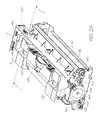
- FIG. 7is a sectional perspective view of the print engine, the section taken through the line 7 - 7 of FIG. 2A ;
- FIG. 8is a sectional elevation of the print engine taken through line 7 - 7 of FIG. 2A , showing the maintenance carousel drawing the wiper blades over the doctor blade;
- FIG. 9is a section view showing the maintenance carousel after drawing the wiper blades over the absorbent cleaning pad
- FIG. 10is a sectional view showing the maintenance carousel being lifted to cap the printhead with the capper maintenance station;
- FIG. 11is a sectional view showing the maintenance carousel being lowered in order to uncap the printhead
- FIG. 12is a sectional view showing the wiper blades wiping the nozzle face of the printhead
- FIG. 13is a sectional view showing the maintenance carousel rotated back to its initial position shown in FIG. 8 where the wiper blades have been drawn past the doctor blade to flick contaminants of the tip region;
- FIG. 14is a sectional view showing the wiper blades been drawn across the absorbent cleaning pad
- FIG. 15is a sectional view showing the maintenance carousel rotated to present the printhead capper to the printhead;
- FIG. 16is a sectional view showing the maintenance carousel being lifted to present the print platen to the printhead;
- FIG. 17is a sectional view showing the way that is carousel being lifted to seal the printhead ICs with the capper;
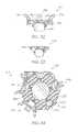
- FIG. 18is a perspective view of the maintenance carousel in isolation
- FIG. 19is another perspective view of the maintenance carousel in isolation in showing the carousel drive spur gear
- FIG. 20is an exploded perspective of the maintenance carousel in isolation
- FIG. 21is a cross-sectional through an intermediate point along the carousel length
- FIG. 22is a schematic section view of a second embodiment of the maintenance carousel, the maintenance carousel presenting a print platen to the printhead;
- FIG. 23is a schematic section view of the second embodiment of the maintenance carousel with the printhead priming station engaging the printhead:
- FIG. 24is a schematic section view of the second embodiment of the maintenance carousel with the wiper blades engaging the printhead;
- FIG. 25is a schematic section view of the second embodiment of the maintenance carousel with an ink spittoon presented to the printhead;
- FIG. 26is a schematic section view of the second time of maintenance carousel with the print platen presented to the printhead as the wiper blades are cleaned on the absorbent pad;
- FIG. 27is a section view of the injection moulded core used in the second embodiment of the maintenance carousel
- FIG. 28is a schematic view of the injection moulding forms being removed from the core of the second embodiment of maintenance carousel
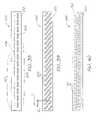
- FIG. 29is a section view of the print platen maintenance station shown in isolation
- FIG. 30is a section view of the printhead capper maintenance station shown in isolation
- FIG. 31is a section view of the wiper blade maintenance station shown in isolation
- FIG. 32is a section view of the printhead priming station shown in isolation
- FIG. 33is a section view of a blotting station shown in isolation
- FIG. 34is a schematic section view of a third embodiment of the maintenance carousel.
- FIG. 35is a sketch of a first embodiment of the wiper member
- FIG. 36is a sketch of a second embodiment of the wiper member
- FIG. 37is a sketch of a third embodiment of the wiper member
- FIG. 38is a sketch of the fourth moment of the wiper member
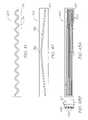
- FIG. 39is a sketch of the fifth embodiment of the wiper member.
- FIG. 40is a sketch of the sixth embodiment of the wiper member
- FIG. 41is a sketch of the seventh embodiment of the wiper member
- FIG. 42is a sketch of the eighth embodiment of the wiper member
- FIGS. 43A and 43Bsketches of a nine embodiment of the wiper member
- FIG. 44is a sketch of a 10th embodiment of the wiper member
- FIG. 45is sketch of an 11th embodiment of the wiper member
- FIG. 46is sketch of a 12 embodiment of the wiper member
- FIG. 47is the sectional perspective of the print engine without the printhead cartridge for the maintenance carousel
- FIG. 48is a perspective showing the independent drive assemblies used by the print engine
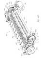
- FIG. 49is an exploded perspective of the independent drive assemblies shown in FIG. 48 ;
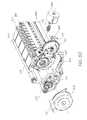
- FIG. 50is an enlarged view of the left end of the exploded perspective showing in FIG. 49 .
- FIG. 1is a schematic overview of the fluidic system used by the print engine described in FIGS. 2A and 2B .
- the print enginehas the key mechanical structures of an inkjet printer.
- the peripheral structuressuch as the outer casing, the paperfeed tray, paper collection tray and so on are configured to suit the specific printing requirements of the printer (for example, the photo printer, the network printer or Soho printer).
- the Applicant's photo printer disclosed in the co-pending application U.S. Ser. No. 11/688,863is an example of an inkjet printer using a fluidic system according to FIG. 1 .
- the contents of this disclosureare incorporated herein by reference.
- the operation of the system and its individual componentsare described in detail in U.S. Ser. No. 11/872,719 the contents of which are incorporated herein by reference.
- the printer fluidic systemhas a printhead assembly 2 supplied with ink from an ink tank 4 via an upstream ink line 8 . Waste ink is drained to a sump 18 via a downstream ink line 16 .
- a single ink lineis shown for simplicity. In reality, the printhead has multiple ink lines for full colour printing.
- the upstream ink line 8has a shut off valve 10 for selectively isolating the printhead assembly 2 from the pump 12 and or the ink tank 4 .
- the pump 12is used to actively prime or flood the printhead assembly 2 .
- the pump 12is also used to establish a negative pressure in the ink tank 4 . During printing, the negative pressure is maintained by the bubble point regulator 6 .
- the printhead assembly 2is an LCP (liquid crystal polymer) molding 20 supporting a series of printhead ICs 30 secured with an adhesive die attach film (not shown).
- the printhead ICs 30have an array of ink ejection nozzles for ejecting drops of ink onto the passing media substrate 22 .
- the nozzlesare MEMS (micro electromechanical) structures printing at true 1600 dpi resolution (that is, a nozzle pitch of 1600 npi), or greater.
- the fabrication and structure of suitable printhead IC's 30are described in detail in U.S. Ser. No. 11/246,687 the contents of which are incorporated by reference.
- the LCP molding 20has a main channel 24 extending between the inlet 36 and the outlet 38 .
- the main channel 24feeds a series of fine channels 28 extending to the underside of the LCP molding 20 .
- the fine channels 28supply ink to the printhead ICs 30 through laser ablated holes in the die attach film.
- the main channel 24is a series of non-priming air cavities 26 .
- These cavities 26are designed to trap a pocket of air during printhead priming.
- the air pocketsgive the system some compliance to absorb and damp pressure spikes or hydraulic shocks in the ink.
- the printersare high speed pagewidth printers with a large number of nozzles firing rapidly. This consumes ink at a fast rate and suddenly ending a print job, or even just the end of a page, means that a column of ink moving towards (and through) the printhead assembly 2 must be brought to rest almost instantaneously. Without the compliance provided by the air cavities 26 , the momentum of the ink would flood the nozzles in the printhead ICs 30 . Furthermore, the subsequent ‘reflected wave’ can generate a negative pressure strong enough to deprime the nozzles.
- FIG. 2Ashows a print engine 3 of the type that uses a print cartridge 2 .
- the print engine 3is the internal structure of an inkjet printer and therefore does not include any external casing, ink tanks or media feed and collection trays.
- the printhead cartridge 2is inserted and removed by the user lifting and lowering the latch 126 .
- the print engine 3forms an electrical connection with contacts on the printhead cartridge 2 and a fluid coupling is formed via the sockets 120 and the inlet and outlet manifolds, 48 and 50 respectively.
- Sheets of mediaare fed through the print engine by the main drive roller 186 and the exit feed roller 178 .
- the main drive roller 186is driven by the main drive pulley and encoder disk 188 .
- the exit feed roller 178is driven by the exit drive pulley 180 which is synchronized to the main drive pulley 188 by the media feed belt 182 .
- the main drive pulley 188is powered by the media feed motor 190 via the input drive belt 192 .
- the main drive pulley 188has an encoder disk which is read by the drive pulley sensor 184 . Data relating to the speed and number of revolutions of the drive shafts 186 and 178 is sent to the print engine controller (or PEC).
- the PEC(not shown) is mounted to the main PCB 194 (printed circuit board) and is the primary micro-processor for controlling the operation of the printer.
- FIG. 2Bshows the print engine 3 with the printhead cartridge removed to reveal the apertures 122 in each of the sockets 120 .
- Each aperture 122receives one of the spouts 52 (see FIG. 5 ) on the inlet and outlet manifolds.
- the ink tankshave an arbitrary position and configuration but simply connect to hollow spigots 124 (see FIG. 8 ) at the rear of the sockets 120 in the inlet coupling.
- the spigot 124 at the rear of the outlet couplingleads to the waste ink outlet in the sump 18 (see FIG. 1 ).
- Reinforced bearing surfaces 128are fixed to the pressed metal casing 196 of the print engine 3 . These provide reference points for locating the printhead cartridge within the print engine. They are also positioned to provide a bearing surface directly opposite the compressive loads acting on the cartridge 2 when installed.
- the fluid couplings 120push against the inlet and outlet manifolds of the cartridge when the manifold spouts (described below) open the shut off valves in the print engine (also described below).
- the pressure of the latch 126 on the cartridge 2is also directly opposed by a bearing surface 128 . Positioning the bearing surfaces 128 directly opposite the compressive loads in the cartridge 2 , the flex and deformation in the cartridge is reduced. Ultimately, this assists the precise location of the nozzles relative to the media feed path. It also protects the less robust structures within the cartridge from damage.
- FIG. 3is a perspective of the complete printhead cartridge 2 .
- the printhead cartridge 2has a top molding 44 and a removable protective cover 42 .
- the top molding 44has a central web for structural stiffness and to provide textured grip surfaces 58 for manipulating the cartridge during insertion and removal.
- the base portion of the protective cover 42protects the printhead ICs (not shown) and line of contacts (not shown) prior to installation in the printer.
- Caps 56are integrally formed with the base portion and cover the ink inlets and outlets (see 54 and 52 of FIG. 5 ).
- FIG. 4shows the printhead assembly 2 with its protective cover 42 removed to expose the printhead ICs on the bottom surface and the line of contacts 33 on the side surface.
- the protective coveris discarded to the recycling waste or fitted to the printhead cartridge being replaced to contain leakage from residual ink.
- FIG. 5is a partially exploded perspective of the printhead assembly 2 .
- the top cover 44has been removed reveal the inlet manifold 48 and the outlet manifold 50 .
- the inlet and outlet shrouds 46 and 47have been removed to better expose the five inlet and outlet spouts ( 52 and 54 ).
- the inlet and outlet manifolds 48 and 50form a fluid connection between each of the individual inlets and outlets and the corresponding main channel (see 24 in FIG. 6 ) in the LCP molding.
- the main channelextends the length of the LCP molding and it feeds a series of fine channels on the underside of the LCP molding.
- a line of air cavities 26are formed above each of the main channels 24 . As explained above in relation to FIG. 1 , any shock waves or pressure pulses in the ink are damped by compressing the air the air cavities 26 .
- FIG. 6is an exploded perspective of the printhead assembly without the inlet or outlet manifolds or the top cover molding.
- the main channels 24 for each ink color and their associated air cavities 26are formed in the channel molding 68 and the cavity molding 72 respectively.
- Adhered to the bottom of the channel molding 68is a die attach film 66 .
- the die attach film 66mounts the printhead ICs 30 to the channel molding such that the fine channels on the underside of the channel molding 68 are in fluid communication with the printhead ICs 30 via small laser ablated holes through the film.
- Both the channel molding 68 and the top cover molding 72are molded from LCP (liquid crystal polymer) because of its stiffness and coefficient of thermal expansion that closely matches that of silicon. It will be appreciated that a relatively long structure such as a pagewidth printhead should minimize any thermal expansion differences between the silicon substrate of the printhead ICs 30 and their supporting structure.
- LCPliquid crystal polymer
- FIG. 7a sectioned perspective view is shown. The section is taken through line 7 - 7 shown in FIG. 2A .
- the printhead cartridge 2is inserted in the print engine 3 such that its outlet manifold 50 is open to fluid communication with the spigot 124 which leads to a sump in the completed printer (typically situated at the base the print engine).
- the LCP molding 20supports the printhead ICs 30 immediately adjacent the media feed path 22 extending through the print engine.
- the printhead maintenance carousel 150On the opposite side of the media feed path 22 is the printhead maintenance carousel 150 and its associated drive mechanisms.
- the printhead maintenance carousel 150is mounted for rotation about the tubular drive shaft 156 .
- the maintenance carousel 150is also configured for movement towards and away from the printhead ICs 30 . By raising the carousel 150 towards the printhead ICs 30 , the various printhead maintenance stations on the exterior of the carousel are presented to the printhead.
- the maintenance carousel 150is rotatably mounted on a lift structure 170 that is mounted to a lift structure shaft 156 such that it can pivot relative to the remainder of the print engine 3 .
- the lift structure 170includes a pair of lift arms 158 (only one lift arm is shown, the other being positioned at the opposite end of the lift structure shaft 156 ).
- Each lift arm 158has a cam engaging surface 168 , such as a roller or pad of low friction material.
- the cams(described in more detail below) are fixed to the carousel drive shaft 160 for rotation therewith.
- the lift arms 158are biased into engagement with the cams on the carousel lift drive shaft 160 , such that the carousel lift motor (described below) can move the carousel towards and away from the printhead by rotating the shaft 160 .
- the rotation of the maintenance carousel 150 about the tubular shaft 166is independent of the carousel lift drive.
- the carousel drive shaft 166engages the carousel rotation motor (described below) such that it can be rotated regardless of whether it is retracted from, or advanced towards, the printhead.
- the wiper blades 162move through the media feed path 22 in order to wipe the printhead ICs 30 .
- the carousel 150can be repeatedly rotated such that the wiper blades 162 engage the doctor blade 154 and the cleaning pad 152 . This is also discussed in more detail below.
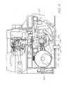
- FIG. 8the cross section 7 - 7 is shown in elevation to better depict the maintenance carousel lift drive.
- the carousel lift drive shaft 160is shown rotated such that the lift cam 172 has pushed the lift arms 158 downwards via the cam engaging surface 168 .
- the lift shaft 160is driven by the carousel lift spur gear 174 which is in turn driven by the carousel lift worm gear 176 .
- the worm gear 176is keyed to the output shaft of the carousel lift motor (described below).
- the maintenance carousel 150With the lift arms 158 drawing the lift structure 170 downwards, the maintenance carousel 150 is retracted away from the printhead ICs 30 . In this position, the carousel 150 can be rotated with none of the maintenance stations touching the printhead ICs 30 . It does, however, bring the wiper blades 162 into contact with the doctor blade 154 and the absorbent cleaning pad 152 .
- the doctor blade 154works in combination with the cleaning pad 152 to comprehensively clean the wiper blades 162 .
- the cleaning pad 152wipes paper dust and dried ink from the wiping contact face of the wiper blades 162 .
- a bead of ink and other contaminantscan form at the tip of the blades 162 where it does not contact the surface of the cleaning pad 152 .
- the doctor blade 154is mounted in the print engine 3 to contact the blades 162 after they have wiped the printhead ICs 30 , but before they contact the cleaning pad 152 .
- the wiper blades 162flex into a curved shaped in order to pass.
- the wiper blades 162are an elastomeric material, they spring back to their quiescent straight shape as soon as they disengage from the doctor blade 154 . Rapidly springing back to their quiescent shape projects dust and other contaminants from the wiper blade 162 , and in particular, from the tip.
- the wiper blades 162also flex when they contact the cleaning pad 152 , and likewise spring back to their quiescent shapes once disengaged from the pad.
- the doctor blade 154is mounted radially closer to the central shaft 166 of the carousel 150 than the cleaning pad 152 . This bends the wiper blades 162 more as they pass, and so imparts more momentum to the contaminants when springing back to the quiescent shape. It is not possible to simply move the cleaning pad 152 closer to the carousel shaft 166 to bend the wiper blades 162 more, as the trailing blades would not properly wipe across the cleaning pad 152 because of contact with the leading blades.
- the cleaning pad 152is an absorbent foam body formed into a curved shape corresponding to the circular path of the wiper blades 162 .
- the pad 152cleans more effectively when covered with a woven material to provide a multitude of densely packed contacts points when wiping the blades. Accordingly, the strand size of the woven material should be relatively small; say less than 2 deniers.
- a microfiber materialworks particularly well with a strand size of about 1 denier.
- the cleaning pad 152extends the length of the wiper blades 162 which in turn extend the length of the pagewidth printhead.
- the pagewidth cleaning pad 152cleans the entire length of the wiper blades simultaneously which reduces the time required for each wiping operation.
- the length of the pagewidth cleaning padinherently provides a large volume of the absorbent material for holding a relatively large amount of ink. With a greater capacity for absorbing ink, the cleaning pad 152 will be replaced less frequently.
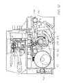
- FIG. 9shows the first stage of capping the printhead ICs 30 with the capping maintenance station 198 mounted to the maintenance carousel 150 .
- the maintenance carousel 150is retracted away from the printhead ICs 30 as the lift cam 172 pushes down on the lift arms 158 .
- the maintenance carousel 150together with the maintenance encoder disk 204 , are rotated until the first carousel rotation sensor 200 and the second carousel rotation sensor 202 determine that the printhead capper 198 is facing the printhead ICs 30 .
- the lift shaft 160rotates the cam 172 so that the lift arms 158 move upwards to advance the maintenance carousel 150 towards the printhead ICs 30 .
- the capper maintenance station 198engages the underside of the LCP moldings 20 to seal the nozzles of the printhead ICs 30 in a relatively humid environment. The ordinary worker will understand that this prevents, or at least prolongs, the nozzles from drying out and clogging.
- FIG. 11shows the printhead ICs 30 being uncapped in preparation for printing.
- the lift shaft 160is rotated so that the lift cam 172 pushes the carousel lift arms 158 downwards.
- the capping maintenance station 198moves away from the LCP molding 20 to expose the printhead ICs 30 .
- FIG. 12shows the printhead ICs 30 being wiped by the wiper blades 162 .
- the blades of the wiper member 162contact the underside of the LCP molding 20 .
- the carousel 150continues to rotate, the wiper blades and drawn across the nozzle face of the printhead ICs 30 to wipe away any paper dust, dried ink or other contaminants.
- the wiper blades 162are formed from elastomeric material so that they resiliently flex and bend as they wipe over the printhead ICs 30 .
- the tip of each wiper bladeis bent over, the side surface of each blade comes into wiping contact with the nozzle face. It will be appreciated that the broad flat side surface of the blades has greater contact with the nozzle face and is more effective at cleaning away contaminants.
- FIGS. 13 and 14show the wiper blades 162 being cleaned. As shown in FIG. 13 , immediately after wiping the printhead ICs 30 , the wiper blades 162 are rotated past the doctor blade 154 . The function of the doctor blade 154 is discussed in greater detail above under the subheading “Doctor Blade”.
- the print platen maintenance station 206is directly opposite the printhead ICs 30 .
- the carouselcan be lifted by rotation of the lift cam 172 so that the nozzles can fire into the absorbent material 208 . Any colour mixing at the ink nozzles is immediately purged.
- Holes (not shown) drilled into the side of the tubular chassis 166provides a fluid communication between the absorbent material 208 and the porous material 210 within the central cavity of the carousel shaft 166 . Ink absorbed by the material 208 is drawn into, and retained by, the porous material 210 .
- the carousel 150can be provided with a vacuum attachment point (not shown) to draw the waste ink away.
- the carousel 150continues to rotate (see FIG. 15 ) until the print platen 206 is again opposite the printhead ICs 30 . As shown in FIG. 16 , the carousel is then lifted towards the printhead ICs 30 in readiness for printing.
- the sheets of media substrateare fed along the media feed path 22 and past the printhead ICs 30 .
- the media substratecan be held away from the platen 206 so that it does not get smeared with ink overspray.
- the absorbent material 208is positioned within a recessed portion of the print platen 206 so that any overspray ink (usually about one millimeter either side of the paper edges) is kept away from surfaces that may contact the media substrate.
- the carousel 150is retracted away from the printhead ICs 30 in rotated so that the printhead capping maintenance station 198 is again presented to the printhead.
- the lift shaft 160rotates the lift cam so that the lift arms 158 move the printhead capping maintenance station 198 into sealing engagement with the underside of the LCP molding 20 .
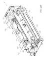
- FIGS. 18 , 19 , 20 and 21show the maintenance carousel in isolation.
- FIG. 18is a perspective view showing the wiper blades 162 and print platen 206 .
- FIG. 19is a perspective view showing the printhead capper 198 and the wiper blades 162 .
- FIG. 20is an exploded perspective showing the component parts of the maintenance carousel, and
- FIG. 21is a section view showing the component parts fully assembled.
- the maintenance carouselhas four printhead maintenance stations; a print platen 206 , a wiper member 162 , a printhead capper 198 and a spittoon/blotter 220 .
- Each of the maintenance stationsis mounted to its own outer chassis component.
- the outer chassis componentsfit around the carousel tubular shaft 166 and interengage each other to lock on to the shaft.
- At one end of the tubular shaft 166is a carousel encoder disk 204 and a carousel spur gear 212 which is driven by the carousel rotation motor (not shown) described below.
- the tubular shaftis fixed to the spur gear or rotation therewith.
- the printhead maintenance stationsrotate together with the tubular shaft by virtue of their firm compressive grip on the shaft's exterior.
- the wiper blade outer chassis component 214is an aluminium extrusion (or other suitable alloy) configured to securely hold the wiper blades 162 .
- the other outer chassis componentsare metal extrusions for securely mounting the softer elastomeric and or absorbent porous material of their respective maintenance stations.
- the outer chassis components for the print platen 216 and the printhead capper 198have a series of identical locking lugs 226 along each of the longitudinal edges.
- the wiper member outer chassis component 214 and the spittoon/blotter outer chassis component 218have complementary bayonet style slots for receiving the locking lugs 226 .
- Each of the bayonet slotshas a lug access aperture 228 adjacent a lug locking slot 230 . Inserting the locking lugs 226 into the lug access aperture 228 of the adjacent outer chassis component, and then longitudinally sliding the components relative to each other will lock them on to the chassis tubular shaft 166 .
- each of the printhead maintenance stationshave an element with a curved shaft engagement surface 234 .
- the print platen 206has an absorbent member 224 with a curved shaft engagement surface 234 formed on one side.
- the spittoon/blotter outer chassis component 218has a relatively large absorbent spittoon/blotter member 220 which also has a curved shaft engagement surface 234 formed on its interior face.
- the outer chassis component for the printhead capper 198 , and the common base of the wiper blades 162 workhas curved shaft engagement surfaces 234 .
- the outer chassis componentscan be assembled in different configurations.
- the wiper blade outer chassis component 214can change positions with the spittoon/blotter chassis component 218 .
- the printhead capper 198can swap with the print platen 206 . In this way the maintenance station can be assembled in a manner that is optimised for the particular printer in which it will be installed.
- FIGS. 22 to 28show another embodiment of the printhead maintenance carousel. These figures are schematic cross sections showing only the carousel and the lower portion of the printhead cartridge. It will be appreciated that the maintenance drive systems require simple and straightforward modifications in order to suit this embodiment of the carousel.
- FIG. 22shows the LCP molding 20 of the printhead cartridge 2 adjacent the printhead maintenance carousel 150 with the print platen 206 presented to the printhead ICs 30 .
- FIG. 29shows the print platen 206 in isolation.
- sheets of media substrateare fed along the media feed path 22 .
- a printing gap 244Between the nozzles of the printhead ICs 30 and the media feed path 22 is a printing gap 244 .
- the gap 244 between the printhead IC nozzle face and the media surfaceshould as close as possible to the nominal values specified during design. In commercially available printers this gap is about two millimeters. However, as print technology is refined, some printers have a printing gap of about one millimeter.
- the arrangement shown in FIG. 22deals with both these issues.
- the paper guide 238 on the LCP molding 20defines the printing gap 244 during printing.
- the print platen 206has a guide surface 246 formed on its hard plastic base molding.
- the guide surface 246directs the leading edge of the sheets towards the exit drive rollers or other drive mechanism.
- With minimal contact between the sheets of media and print platen 206there is a greatly reduced likelihood of smearing from over sprayed ink during full bleed printing.
- placing the paper guide 238 on the LCP molding 20 immediately adjacent the printhead ICs 30accurately maintains the gap 244 from the nozzles to the media surface.
- Some printers in the Applicant's rangeuse this to provide a printing gap 244 of 0.7 millimeters. However this can be further reduced by flattening the bead of encapsulant material 240 adjacent the printhead ICs 30 .
- Power and datais transmitted to the printhead ICs 30 by the flex PCB 242 mounted to the exterior of the LCP molding 20 .
- the contacts of the flex PCB 242are electrically connected to the contacts of the printhead ICs 30 by a line of wire bonds (not shown). To protect the wire bonds, they are encapsulated in an epoxy material referred to as encapsulant.
- the Applicanthas developed several techniques for flattening the profile of the wire bonds and the bead of encapsulant 240 covering them. This in turn allows the printing gap 244 to be further reduced.
- the print platen 206has an indentation or central recessed portion 248 which is directly opposite the nozzles of the printhead ICs 30 . Any over spray ink will be in this region of the platen 206 . Recessing this region away from the remainder of the platen ensures that the media substrate will not get smeared with wet over spray ink.
- the surface of the central recessed 248is in fluid communication with an absorbent fibrous element 250 .
- the fibrous element 250is in fluid communication with porous material 254 in the centre of the chassis 236 by capillary tubes 252 . Over sprayed ink is wicked into the fibrous element 250 and drawn into the porous material 254 by capillary action through the tubes 252 .
- FIG. 23shows the carousel 150 rotated such that the printhead priming station 262 is presented to the printhead ICs 30 .
- FIG. 30shows the printhead priming station 272 and its structural features in isolation.
- the printhead priming stationhas an elastomeric skirt 256 surrounding a priming contact pad 258 formed of porous material.
- the elastomeric skirt and the priming contact padare co-molded together with a rigid polymer base 260 which securely mounts to the injection molded chassis 236 .
- the maintenance carousel 150is raised so that the priming contact pad 258 covers the nozzles of the printhead ICs 30 .
- Holding the contact pad 258 against the nozzle array as it is primed under pressuresignificantly reduces the volume of ink purged through the nozzles.
- the porous materialpartially obstructs the nozzles to constrict the flow of ink.
- the elastomeric skirt 256seals against the underside of the LCP molding 22 to capture any excess ink that may flow from the sides of the contact pad 258 .
- Flow apertures 264 formed in the rigid polymer base 260allows the ink absorbed by the pad 258 and any excess ink to flow to the absorbent fibrous element 250 (identical to that used by the print platen 206 ).
- ink in the fibrous element 250is drawn into the porous material 254 within the injection molded chassis 236 by the capillary tubes 252 .
- the printhead priming station 262By using the printhead priming station 262 , the amount of wasted ink is significantly reduced. Without the priming station, the volume of ink wasted when priming the pagewidth printhead is typically about two milliliters per colour. With the priming station 262 , this is reduced to 0.1 milliliters per colour.
- the priming contact pad 258need not be formed of porous material. Instead, the pad can be formed from the same elastomeric material as the surrounding skirt 256 . In this case, the contact pad 258 needs to have a particular surface roughness.
- the surface that engages the nozzle face of the printhead ICs 30should be rough at the 2 to 4 micron scale, but smooth and compliant at the 20 micron scale. This type of surface roughness allows air to escape from between the nozzle face and contact pad, but only a small amount of ink.
- FIG. 24shows the maintenance carousel 150 with the wiping station 266 presented to the printhead ICs 30 .
- the wiping stationis shown in isolation in FIG. 31 .
- the wiping station 266is also a co-molded structure with the soft elastomeric wiper blades 268 supported on a hard plastic base 270 .
- the carousel chassis 236is raised and then rotated so that the wiper blades 268 wipe across the nozzle face.
- the carousel chassis 236is rotated so that the wiper blades 268 wipe towards the encapsulation bead 240 .
- the encapsulant bead 240can be profiled to assist the dust and contaminants to lodge on the face of the wiper blade 268 .
- the maintenance drive(not shown) can easily be configured to rotate the chassis 236 in both directions if wiping in two directions proves more effective.
- the number of wipes across the printhead ICs 30is easily varied by changing the number of rotations the maintenance drive is programmed to perform for each wiping operation.
- FIG. 25the maintenance carousel 150 is shown with the printhead capper 272 presented to the printhead ICs 30 .
- FIG. 32shows the capper in isolation to better illustrate its structure.
- the capper 272has a perimeter seal 274 formed of soft elastomeric material.
- the perimeter seal 274is co-molded with its hard plastic base 276 .
- the printhead capper 272reduces the rate of nozzle drying when the printer is idle.
- the seal between the perimeter seal 274 and the underside of the LCP molding 20need not be completely air tight as the capper is being used to prime printhead using a suction force.
- the hard plastic base 276should include an air breather hole 278 so that the nozzles do not flood by the suction caused as the printhead is uncapped.
- the chassis 236is rotated until the printhead capper 272 is presented to the printhead ICs 30 .
- the chassis 236is then raised until the perimeter seal 274 engages the printhead cartridge 2 .
- FIG. 26shows the inclusion of the wiper blade cleaning pad 152 .
- the cleaning pad 152is mounted in the printer so that the wiper blades 268 move across the surface of the pad 152 as the maintenance carousel 150 is rotated.
- the chassis 236can be rotated at relatively high speeds for a comprehensive clean of the wiper blades 268 while not risking any damaging contact with the printhead ICs 30 .
- the cleaning pad 152can be wetted with a surfactant to better remove contaminants from the wiper blades surface.
- FIG. 27shows the injection molded chassis 236 in isolation.
- the chassisis symmetrical about two planes extending through the central longitudinal axis 282 . This symmetry is important because an injection molded chassis extending the length of pagewidth printhead, is prone to deform and bend as it cools if the cross section is not symmetrical. With a symmetrical cross-section, the shrinkage of the chassis is it cools is also symmetrical.
- the chassis 236has four maintenance station mounting sockets 276 formed in its exterior surface.
- the sockets 276are identical so that they can receive any one of the various maintenance stations ( 206 , 266 , 262 , 272 ). In this way the maintenance stations become interchangeable modules and the order which the maintenance stations are presented to the printhead can be changed to suit different printers. Furthermore, if the maintenance stations themselves are modified, their standard sockets ensure they are easily incorporated into the existing production line with a minimum of retooling.
- the maintenance stationsare secured in the sockets with adhesive but other methods such as an ultra sonic spot weld or mechanical interengagement would also be suitable.
- the moldhas four sliders 278 and a central core 288 .
- Each of the sliders 278has columnar features 280 to form the conduits connecting the fibrous wicking pads to the porous material 219 in the central cavity.
- the line of draw for each slideris radially outwards from the chassis 236 while the core 288 is withdrawn longitudinally (it will be appreciated that the core is not a precisely a cylinder, but a truncated cone to provide the necessary draft).
- Injection molding of polymer componentsis very well suited to high-volume, low-cost production.
- the symmetrical structure of the chassis and uniform shrinkagemaintain good tolerances to keep the maintenance stations extending parallel to the printhead ICs.
- the chassisis configured for connection to a vacuum source to periodically drain ink from the porous material 210 .
- FIG. 34shows an embodiment of the printhead maintenance carousel 150 with five different maintenance stations: a print platen 206 , a printhead wiper 266 , a printhead capper 272 , a priming station 262 and a spittoon 284 .
- the spittoon 284(shown in isolation in FIG. 33 ) has a relatively simple structure—the spittoon face 284 presents flat to the printhead and has apertures (not shown) for fluid communication with the fibrous element 250 retained in its hard plastic base.
- the five station maintenance carousel 150adds a spittoon 284 to allow the printer to use major ink purges as part of the maintenance regime.
- the four station carousel of FIGS. 22-25will accommodate minor ink purges or ‘spitting cycles’ using the print platen 206 and or the capper 272 .
- a minor spitting cycleis used after a nozzle face wipe or as an inter-page spit during a print job to keep the nozzles wet.
- a major spitting cyclewill be required—one which is beyond the capacity of the platen or the capper.
- the spittoon 284has large apertures in its face 286 or a series of retaining ribs to hold the fibrous wicking material 250 in the hard plastic base. This keeps the fibrous element 250 very open to a potentially dense spray of ink. One face of the fibrous element 250 presses against the capillary tubes 252 to enhance the flow to the porous material 254 in the central cavity of the chassis 236 .
- the five socket chassis 236is injection molded using five sliders configured at 72 degrees to each other, or six sliders at 60 degrees to each other. Similarly, a maintenance carousel with more than five stations is also possible. If the nozzle face is prone to collecting dried ink, it can be difficult to remove with a wiper alone. In these situations, the printer may require a station (not shown) for jetting ink solvent or other cleaning fluid onto the nozzle face. This can be incorporated instead of, or in addition to the spittoon.
- FIG. 35 to 46show a range of different structures that the wiper can take. Wiping the nozzle face of printhead is an effective way of removing paper dust, ink floods, dried ink or other contaminants. The ordinary worker will appreciate that countless different wiper configurations are possible, of which, the majority will be unsuitable for any particular printer. The functional effectiveness of wiper (in terms of cleaning the printhead) must be weighed against the production costs, the intended operational life, the size and weight constraints and other considerations.
- FIG. 35shows a wiper maintenance station 266 with a single elastomeric blade 290 mounted in the hard plastic base 270 such that it extends normal to the media feed direction.
- a single wiper blade extending the length of the nozzle arrayis a simple wiping arrangement with low production and assembly costs.
- a single blade wiperis suited to printers and the lower end of the price range.
- the higher production volumesfavor cost efficient manufacturing techniques and straightforward assembly of the printer components. This may entail some compromise in terms of the operational life of the unit, or the speed and efficiency with which the wiper cleans the printhead.
- the single blade designis compact and if it does not effectively clean the nozzle face in a single traverse, the maintenance drive can simply repeat the wiping operation until the printhead is clean.
- FIGS. 36 , 43 A, 43 and 46show wiper maintenance stations 266 with multiple, parallel blades.
- the twin parallel blades 292are identical and extend normal to the media feed direction. Both blades 292 are separately mounted to the hard plastic base 270 so as to operate independently.
- the bladesare non-identical.
- the first and second blades ( 294 and 296 respectively)are different widths (or otherwise different cross sectional profiles) and durometer values (hardness and viscoelasticity). Each blade may be optimised to remove particular types of contaminant. However, they are separately mounted in the hard plastic base 270 for independent operation. In contrast, the multiple blade element of FIGS.
- 43A and 43Bhas smaller, shorter blades 300 all mounted to a common elastomeric base 298 , which is in turn secured to the hard plastic base 270 .
- Thisis a generally more compliant structure that has a relatively large surface area in contact with the nozzle face with each wipe.
- the thin soft bladeswear and perish at a greater rate than the larger and more robust blades.
- FIG. 37shows a wiper maintenance station 266 with a single blade 302 mounted in the hard plastic base 270 such that it is skew to the wiping direction. It will be appreciated that the wiping direction is normal to the longitudinal extent of the plastic base 270 .
- a single wiper bladeis a simple wiping arrangement with low production and assembly costs. Furthermore, by mounting the blade so that it is skew to the wiping direction, the nozzle face will be in contact with only one section of blade and any time during the traverse of the wiper member. With only one section in contact with the nozzle face, the blade does not buckle or curl because of inconsistent contact pressure along its full length. This ensures sufficient contact pressure between the wiper blade and all of the nozzle face without needing to precisely line the blade so that it is completely parallel to the nozzle face. This allows the manufacturing tolerances to be relaxed so that higher volume low-cost production techniques can be employed. This may entail some compromise in terms of increasing the distance that the wiper member must travel in order to clean the printhead, and therefore increasing the time required from each wiping operation. However the reduced manufacturing costs outweigh these potential disadvantages.
- FIG. 38shows a wiper maintenance station 266 with two sectioned blades 304 mounted in the hard plastic base 270 .
- the individual blade sections 306 in each blade 304are positioned so that they are out of registration with each other with respect to the wiping direction. In this way, the nozzles that are not wiped by the first blade 304 because they are positioned in a gap between two blade sections 306 , will be wiped by a blade section 306 in the second blade 304 .
- Wiping the nozzle face of pagewidth printhead with a single long bladecan be ineffective. Inconsistent contact pressure between the blade and the nozzle face can cause the blade to buckle or curl at certain sections along its length. In these sections the contact pressure can be insufficient or there maybe no contact between the blade and the nozzle face.
- a wiper blade divided into individual blade sectionscan address this problem. Each section is capable of moving relative to its adjacent sections so any inconsistencies in the contact force, will not cause buckling or curling in other sections of blade. In this may contact pressure is maintained at the nozzle face is clean effectively.
- the wiper maintenance station 266has a series of independent blades 308 mounted in the hard plastic base 270 such that they are skew to the wiping direction.
- the blades 308are positioned so that the lateral extent (with respect the wiping direction) of each blade (X) has some overlap (Z) with the lateral extent of its adjacent blades (Y).
- the inventionuses a series of adjacent skew blades, each individual blade wiping a corresponding portion of the nozzle array. Multiple blades involve higher manufacturing costs than a single blade but in certain applications, the compact design and quicker operation outweigh these potential disadvantages.
- the wiping maintenance stations 266use an array of contact pads 310 instead of any blade configurations.
- the individual pads 312maybe short squad cylinders of an elastomeric material individually mounted into the hard plastic base 270 or a cylindrical soft fibre brush similar to the format often used for silicon wafer cleaning.
- wiping the nozzle face of pagewidth printhead with a single long contact surfacecan be ineffective. Inconsistent contact pressure between the wiping surface and the nozzle face can cause the contact pressure to be insufficient or non-existent in some areas.
- Using a wiping surface that has been divided into an array 310 of individual contact padsallows each pad to move relative to its adjacent pads so any inconsistencies in the contact force will vary the amount each pad compresses and deforms individually. Relatively high compression of one pad will not necessarily transfer compressive forces to its adjacent pad. In this way, uniform contact pressure is maintained at the nozzle face is cleaned more effectively.
- the single blade 314is mounted into the hard plastic base 270 such that it follows a sinusoidal path.
- wiping the nozzle face of pagewidth printhead with a single long contact surfacecan be ineffective. Inconsistent contact pressure between the wiping surface and the nozzle face can cause the contact pressure to be insufficient or non-existent in some areas.
- One of the reasons that the contact pressure will varyis inaccurate movement of the wiper surface relative to the nozzle face. If the support structure for the wiping surface is not completely parallel to the nozzle face over the entire length of travel during the wiping operation, there will be areas of low contact pressure which may not be properly cleaned.
- a wiping bladethat has a zigzag or sinusoidal shape wipes the nozzle face with a number wiper sections that are inclined to the media feed direction. This configuration also keeps the length of travel of the wiper member relative to the printhead small enough to remain accurate and compact.
- FIG. 42shows the wiping maintenance station 266 with a single blade 316 having two linear sections mounted on the hard plastic base 270 at an angle to each other, and skew to the wiping direction.
- wiping the nozzle face of pagewidth printhead with a single long contact surfacecan cause the contact pressure to be insufficient or non-existent in some areas.
- Angling the blade relative to the wiping direction and the printhead nozzle facemeans that only one portion of the wiper blade contacts the nozzle face at any time during the wiping operation. This keeps the contact pressure more uniform but it requires the wiper blade to travel further for each wiping operation.
- inaccuracies in the movement of wiper surface relative to the nozzle facesource of insufficient contact pressure. Increasing the length of wiper travel only increases the risk of such inaccuracies.
- the contact bladecan have a shallow V-shape or U-shape. Furthermore if the leading edge of the blade 318 is the intersection of the two linear sections (or the curved section of the U-shaped blade), the Applicant has found that there is less blade wear because of the additional support provided to the initial point of contact with the nozzle face.
- FIG. 45shows a printhead wiper maintenance station 266 with a fibrous pad 320 mounted to the hard plastic base 270 .
- a fibrous pad 320is particularly effective for wiping the nozzle face.
- the padpresents many points of contact with the nozzle face so that the fibres can mechanically engage with solid contaminants and will wick away liquid contaminants like ink floods and so on.
- the fibrous padcan be heavily laden with contaminants and may no longer clean the nozzle face effectively.
- printers intended to have a short operational life, or printers that allow the wiper to be replaced, a fibrous padwill offer the most effective wiper.
- a wiperthat has a combination of the above wiping structures.
- a single bladein combination with a series of skew blades, or a series of parallel blades with a fibrous pad in between.
- the combination wiper maintenance stationcan be derived by choosing the specific wiping structures on the basis of their individual merits and strength.
- FIGS. 47 to 50show the media feed drive and the printhead maintenance drive in greater detail.
- FIG. 48shows the printhead maintenance carousel 150 and the drive systems in isolation.
- the maintenance carousel 150is shown with the wiper blades 162 presented to the printhead (not shown).
- the perspective shown in FIG. 48reveals the paper exit guide 322 leading to the exit drive roller 178 .
- the main drive roller shaft 186is shown extending from the main drive roller pulley 330 . This pulley is driven by the main drive roller belt 192 which engages the media feed motor 190 .
- the media feed drive belt 182synchronises the rotation of the main drive roller 186 and the exit roller 178 .
- the exploded perspective in FIG. 49shows the individual components in greater detail.
- this perspectivebest illustrates the balanced carousel lift mechanism.
- the carousel lift drive shaft 160extends between two identical carousel lift cams 172 .
- One end of the carousel lift shaft 160is keyed to the carousel lift spur gear 174 .
- the spur gear 174meshes with the worm gear 176 driven by the carousel lift motor 324 .
- the carousel lift rotation sensor 334provides feedback to the print engine controller (not shown) which can determine the displacement of the carousel from the printhead by the angular displacement of the cams 172 .
- FIG. 47is a section view taken along line 7 - 7 of FIG. 2A with the printhead cartridge 2 removed and the printhead maintenance carousel 150 also removed. This figure provides a clear view of the carousel lift spur gear 174 , its adjacent lift cam 172 and the corresponding carousel lift arm 158 .
- the carousel lift driveis completely balanced and symmetrical when lifting and lowering the carousel. This serves to keep the various printhead maintenance stations parallel to the longitudinal extent of the printhead ICs.
- the carousel rotation driveis best illustrated in the enlarged exploded partial perspective of FIG. 50 .
- the carousel rotation motor 326is mounted to the side of the carousel lift structure 170 .
- the stepper motor sensor 328provides feedback to the print engine controller (PEC) regarding the speed and rotation of the motor 326 .
- the carousel rotation motor 326drives the idler gear 332 which in turn, drives the reduction gear (not shown) on the obscured side of the carousel lift structure 170 .
- the reduction gearmeshes with the carousel spur gear 212 which is keyed to the carousel chassis for rotation therewith.
- the printerhas a broad range of maintenance procedures from which to choose.
- the carousel rotation motor 326can be driven in either direction and at the variable speeds. Accordingly the nozzle face can be wiped in either direction and the wiper blades can be cleaned against the absorbent pad 152 in both directions. This is particularly useful if paper dust or other contaminants passed to the nozzle face because of a mechanical engagement with the surface irregularity on the nozzle face. Wiping in the opposite direction will often dislodge such mechanical engagements.
- wiper blades 162can slow down for initial contact with the nozzle face and subsequently increase speed while wiping.
- the wiper blades 162can be moved past the doctor blade 154 at a greater speed than the blades are moved over the cleaning pad 152 .
- the blades 162can be wiped in both directions with any number of revolutions in either direction. Furthermore the order in which the various maintenance stations are presented to the printhead can be easily programmed into the PEC and or left to the discretion of the user.
Landscapes
- Developing Agents For Electrophotography (AREA)
- Detergent Compositions (AREA)
- Medicines That Contain Protein Lipid Enzymes And Other Medicines (AREA)
Abstract
Description
| 12/014,767 | 12/014,768 | 12/014,769 | 12/014,770 | 12/014,771 | 7,758,149 |
| 12/014,773 | 7,758,152 | 12/014,775 | 7,753,477 | 12/014,778 | 12/014,779 |
| 12/014,780 | 12/014,781 | 12/014,782 | 12/014,783 | 12/014,784 | 12/014,785 |
| 12/014,787 | 7,753,478 | 12/014,789 | 12/014,790 | 12/014,791 | 7,771,002 |
| 12/014,793 | 7,766,451 | 7,771,007 | 12/014,798 | 12/014,801 | 12/014,803 |
| 12/014,804 | 12/014,805 | 12/014,806 | 12/014,807 | ||
| 6,276,850 | 6,520,631 | 6,158,907 | 6,539,180 | 6,270,177 | 6,405,055 |
| 6,628,430 | 6,835,135 | 6,626,529 | 6,981,769 | 7,125,338 | 7,125,337 |
| 7,136,186 | 7,286,260 | 7,145,689 | 7,130,075 | 7,081,974 | 7,177,055 |
| 7,209,257 | 6,443,555 | 7,161,715 | 7,154,632 | 7,158,258 | 7,148,993 |
| 7,075,684 | 7,400,346 | 7,385,630 | 7,385,629 | 7,385,628 | 7,460,153 |
| 6,966,659 | 6,988,841 | 7,077,748 | 7,255,646 | 7,070,270 | 7,014,307 |
| 7,158,809 | 7,217,048 | 7,430,067 | 7,341,341 | 7,567,221 | 7,548,220 |
| 7,271,829 | 7,465,109 | 7,431,519 | 7,777,856 | 7,469,982 | 11/520,735 |
| 11/505,858 | 7,556,564 | 7,556,371 | 7,506,943 | 7,695,082 | 7,460,882 |
| 7,564,580 | 7,215,441 | 11/650,545 | 7,056,040 | 6,942,334 | 7,556,325 |
| 11/740,265 | 7,461,985 | 7,470,021 | 7,572,003 | 7,458,678 | 7,688,351 |
| 11/750,285 | 7,654,905 | 7,461,934 | 7,726,805 | 11/845,669 | 6,799,853 |
| 7,237,896 | 6,749,301 | 7,740,579 | 7,137,678 | 7,252,379 | 7,144,107 |
| 7,426,050 | 7,690,785 | 7,573,501 | 7,220,068 | 7,270,410 | 7,241,005 |
| 7,108,437 | 7,140,792 | 7,224,274 | 7,463,283 | 10/503,927 | 7,590,545 |
| 7,349,777 | 7,354,121 | 7,195,325 | 7,229,164 | 7,150,523 | 10/503,889 |
| 7,154,580 | 6,906,778 | 7,167,158 | 7,128,269 | 6,688,528 | 6,986,613 |
| 6,641,315 | 7,278,702 | 7,625,054 | 7,150,524 | 7,155,395 | 6,915,140 |
| 6,999,206 | 6,795,651 | 6,883,910 | 7,118,481 | 7,136,198 | 7,092,130 |
| 6,786,661 | 6,808,325 | 7,448,747 | 7,448,746 | 7,219,990 | 7,591,553 |
| 6,750,901 | 6,476,863 | 6,788,336 | 6,322,181 | 6,597,817 | 6,227,648 |
| 6,727,948 | 6,690,419 | 7,431,281 | 6,619,654 | 6,969,145 | 6,679,582 |
| 7,328,896 | 6,568,670 | 6,866,373 | 7,280,247 | 7,008,044 | 6,742,871 |
| 6,966,628 | 6,644,781 | 6,969,143 | 6,767,076 | 6,834,933 | 6,692,113 |
| 6,913,344 | 6,727,951 | 7,128,395 | 7,036,911 | 7,032,995 | 6,969,151 |
| 6,955,424 | 6,969,162 | 7,456,861 | 6,942,315 | 7,354,122 | 7,234,797 |
| 6,986,563 | 7,295,211 | 7,701,506 | 7,286,162 | 7,283,159 | 7,077,330 |
| 6,196,541 | 7,303,257 | 7,465,012 | 7,226,144 | 7,461,918 | 7,267,428 |
| 7,401,891 | 7,380,924 | 7,093,929 | 7,690,764 | 7,441,870 | 7,629,999 |
| 7,290,862 | 7,646,403 | 7,591,528 | 6,195,150 | 7,581,814 | 7,775,639 |
| 11/854,435 | 11/853,817 | 7,413,285 | 7,712,867 | 6,362,868 | 7,597,314 |
| 6,831,681 | 6,431,669 | 6,362,869 | 6,472,052 | 6,356,715 | 6,894,694 |
| 6,636,216 | 6,366,693 | 6,329,990 | 6,459,495 | 6,137,500 | 6,690,416 |
| 7,050,143 | 6,398,328 | 7,110,024 | 6,431,704 | 6,879,341 | 6,415,054 |
| 6,665,454 | 6,542,645 | 6,486,886 | 6,381,361 | 6,317,192 | 6,850,274 |
| 6,646,757 | 6,624,848 | 6,357,135 | 6,271,931 | 6,353,772 | 6,106,147 |
| 6,665,008 | 6,304,291 | 6,305,770 | 6,289,262 | 6,315,200 | 6,217,165 |
| 6,496,654 | 6,859,225 | 6,924,835 | 6,647,369 | 6,943,830 | 7,535,582 |
| 7,021,745 | 6,712,453 | 6,460,971 | 6,428,147 | 6,416,170 | 6,402,300 |
| 6,464,340 | 6,612,687 | 6,412,912 | 6,447,099 | 6,837,567 | 6,505,913 |
| 7,128,845 | 6,733,684 | 7,249,108 | 6,566,858 | 6,331,946 | 6,246,970 |
| 6,442,525 | 7,346,586 | 7,685,423 | 6,374,354 | 7,246,098 | 6,816,968 |
| 6,757,832 | 6,334,190 | 6,745,331 | 7,249,109 | 7,197,642 | 7,093,139 |
| 7,509,292 | 7,685,424 | 7,743,262 | 7,210,038 | 7,401,223 | 7,702,926 |
| 7,716,098 | 7,757,084 | 7,747,541 | 7,657,488 | 7,119,836 | 7,283,162 |
| 7,286,169 | 7,724,282 | 7,170,652 | 6,967,750 | 6,995,876 | 7,099,051 |
| 7,172,191 | 7,243,916 | 7,222,845 | 7,559,472 | 7,285,227 | 7,063,940 |
| 7,453,586 | 7,193,734 | 7,086,724 | 7,090,337 | 7,278,723 | 7,140,717 |
| 7,558,476 | 7,773,245 | 7,256,824 | 7,140,726 | 7,156,512 | 7,186,499 |
| 7,461,924 | 7,525,687 | 7,357,497 | 7,530,665 | 7,404,633 | 6,750,944 |
| 7,468,810 | 7,291,447 | 7,556,257 | 7,533,877 | 11/778,561 | 7,665,834 |
| 11/869,710 | 7,468,140 | 11/927,403 | 7,590,347 | 7,633,535 | 6,985,207 |
| 6,773,874 | 6,650,836 | 7,324,142 | 7,705,891 | 7,250,975 | 7,295,343 |
| 6,880,929 | 7,236,188 | 7,236,187 | 7,155,394 | 7,557,829 | 7,609,411 |
| 7,055,927 | 6,986,562 | 7,052,103 | 7,312,845 | 7,492,490 | 10/656,791 |
| 7,375,746 | 7,602,423 | 7,289,142 | 7,095,533 | 6,914,686 | 6,896,252 |
| 6,820,871 | 6,834,851 | 6,848,686 | 6,830,246 | 6,851,671 | 7,460,152 |
| 7,092,011 | 7,187,404 | 7,483,050 | 10/753,458 | 6,878,299 | 6,929,348 |
| 6,921,154 | 7,453,492 | 6,913,346 | 7,576,795 | 7,576,794 | 7,385,639 |
| 7,557,853 | 7,714,889 | 7,593,058 | 7,246,897 | 7,077,515 | 7,551,202 |
| 7,505,068 | 10/853,659 | 7,747,154 | 6,913,875 | 7,021,758 | 7,033,017 |
| 7,161,709 | 7,099,033 | 7,147,294 | 7,156,494 | 7,360,872 | 7,434,915 |
| 7,032,998 | 7,044,585 | 7,296,867 | 6,994,424 | 7,384,134 | 7,258,435 |
| 7,097,263 | 7,001,012 | 7,004,568 | 7,040,738 | 7,188,933 | 7,027,080 |
| 7,025,446 | 6,991,321 | 7,131,715 | 7,261,392 | 7,207,647 | 7,182,435 |
| 7,097,285 | 7,331,646 | 7,097,284 | 7,083,264 | 7,147,304 | 7,232,203 |
| 7,156,498 | 7,201,471 | 7,465,023 | 7,549,728 | 7,517,057 | 7,210,764 |
| 7,381,342 | 7,520,593 | 7,465,026 | 7,524,029 | 7,407,265 | 7,581,816 |
| 7,618,110 | 6,710,457 | 6,775,906 | 6,507,099 | 7,221,043 | 7,107,674 |
| 7,154,172 | 7,402,894 | 7,247,941 | 7,402,896 | 7,307,354 | 7,479,697 |
| 6,530,339 | 6,631,897 | 6,851,667 | 6,830,243 | 6,860,479 | 6,997,452 |
| 7,000,913 | 7,204,482 | 7,398,967 | 7,793,926 | 7,401,989 | 6,238,044 |
| 6,425,661 | 7,364,256 | 7,258,417 | 7,293,853 | 7,328,968 | 7,270,395 |
| 7,461,916 | 7,510,264 | 7,334,864 | 7,255,419 | 7,284,819 | 7,229,148 |
| 7,258,416 | 7,273,263 | 7,270,393 | 6,984,017 | 7,347,526 | 7,357,477 |
| 7,156,497 | 7,726,778 | 7,780,261 | 7,562,960 | 7,775,625 | 7,524,017 |
| 11/853,816 | 11/853,814 | 11/853,786 | 11/872,037 | 11/856,694 | 7,744,190 |
| 11/971,170 | 7,465,015 | 7,364,255 | 7,357,476 | 7,758,148 | 7,284,820 |
| 7,341,328 | 7,246,875 | 7,322,669 | 11/764,760 | 11/853,777 | 11/955,354 |
| 7,445,311 | 7,452,052 | 7,455,383 | 7,448,724 | 7,441,864 | 7,637,588 |
| 7,648,222 | 7,669,958 | 7,607,755 | 7,699,433 | 7,658,463 | 6,431,777 |
| 6,334,664 | 6,447,113 | 7,239,407 | 6,398,359 | 6,652,089 | 6,652,090 |
| 7,057,759 | 6,631,986 | 7,187,470 | 7,280,235 | 7,414,749 | 11/744,210 |
| 7,744,208 | 6,471,331 | 6,676,250 | 6,347,864 | 6,439,704 | 6,425,700 |
| 6,588,952 | 6,626,515 | 6,722,758 | 6,871,937 | 7,794,066 | 7,344,226 |
| 7,328,976 | 7,794,613 | 7,669,967 | 11/685,090 | 11/740,925 | 7,605,009 |
| 7,568,787 | 11/946,840 | 7,441,879 | 7,249,942 | 7,206,654 | 7,162,324 |
| 7,162,325 | 7,231,275 | 7,146,236 | 7,278,847 | 10/753,499 | 6,997,698 |
| 7,220,112 | 7,231,276 | 7,373,214 | 7,220,115 | 7,195,475 | 7,144,242 |
| 7,306,323 | 7,306,319 | 7,467,837 | 7,322,674 | 7,513,596 | 7,416,276 |
| 11/736,545 | 7,467,025 | 7,556,329 | 7,797,071 | 7,706,909 | 7,776,641 |
| 11/853,755 | 7,591,536 | 7,597,420 | 7,658,464 | 6,786,420 | 6,827,282 |
| 6,948,661 | 7,073,713 | 7,485,825 | 7,093,762 | 7,083,108 | 7,222,799 |
| 7,201,319 | 7,524,045 | 7,703,910 | 11/518,238 | 11/518,280 | 7,663,784 |
| 11/518,242 | 7,032,899 | 6,854,724 | 7,331,651 | 7,334,870 | 7,334,875 |
| 7,416,283 | 7,438,386 | 7,461,921 | 6,350,023 | 6,318,849 | 6,592,207 |
| 6,439,699 | 6,312,114 | 7,506,958 | 7,472,981 | 7,448,722 | 7,575,297 |
| 7,438,381 | 7,441,863 | 7,438,382 | 7,425,051 | 7,399,057 | 7,695,097 |
| 7,686,419 | 7,753,472 | 7,448,720 | 7,448,723 | 7,445,310 | 7,399,054 |
| 7,425,049 | 7,367,648 | 7,370,936 | 7,401,886 | 7,506,952 | 7,401,887 |
| 7,384,119 | 7,401,888 | 7,387,358 | 7,413,281 | 7,530,663 | 7,467,846 |
| 7,669,957 | 7,771,028 | 7,758,174 | 7,695,123 | 7,798,600 | 7,604,334 |
| 11/482,987 | 7,708,375 | 7,695,093 | 7,695,098 | 7,722,156 | 7,703,882 |
| 7,510,261 | 7,722,153 | 7,581,812 | 7,641,304 | 7,753,470 | 10/803,074 |
| 7,570,389 | 7,040,823 | 7,535,599 | 7,528,987 | 7,661,779 | 10/803,079 |
| 10/922,971 | 7,672,012 | 10/922,842 | 7,692,815 | 7,419,259 | 7,125,185 |
| 7,229,226 | 7,364,378 | 7,465,019 | 7,243,835 | 10/815,630 | 7,703,693 |
| 10/815,638 | 7,251,050 | 10/815,642 | 7,097,094 | 7,137,549 | 10/815,618 |
| 7,156,292 | 7,427,015 | 10/815,635 | 7,357,323 | 7,654,454 | 7,137,566 |
| 7,131,596 | 7,128,265 | 7,207,485 | 7,197,374 | 7,175,089 | 10/815,617 |
| 7,537,160 | 7,178,719 | 7,506,808 | 7,207,483 | 7,296,737 | 7,270,266 |
| 7,314,181 | 11/488,162 | 11/488,163 | 11/488,167 | 11/488,168 | 11/488,165 |
| 11/488,166 | 7,267,273 | 7,383,991 | 7,383,984 | 7,637,437 | 7,605,940 |
| 7,128,270 | 7,784,681 | 7,677,445 | 7,506,168 | 7,441,712 | 7,663,789 |
| 7,681,800 | 7,461,778 | 11/863,257 | 11/863,258 | 11/041,609 | 11/041,626 |
| 7,537,157 | 7,801,742 | 7,395,963 | 11/863,269 | 7,637,419 | 7,676,382 |
| 7,464,879 | 7,457,961 | 7,739,509 | 7,467,300 | 7,467,299 | 7,565,542 |
| 11/863,263 | 7,469,819 | 7,484,101 | 7,472,278 | 7,467,301 | 7,457,007 |
| 7,150,398 | 7,159,777 | 7,450,273 | 7,188,769 | 7,097,106 | 7,070,110 |
| 7,243,849 | 7,314,177 | 7,469,836 | 7,568,629 | 7,566,009 | 6,227,652 |
| 6,213,588 | 6,213,589 | 6,231,163 | 6,247,795 | 6,394,581 | 6,244,691 |
| 6,257,704 | 6,416,168 | 6,220,694 | 6,257,705 | 6,247,794 | 6,234,610 |
| 6,247,793 | 6,264,306 | 6,241,342 | 6,247,792 | 6,264,307 | 6,254,220 |
| 6,234,611 | 6,302,528 | 6,283,582 | 6,239,821 | 6,338,547 | 6,247,796 |
| 6,557,977 | 6,390,603 | 6,362,843 | 6,293,653 | 6,312,107 | 6,227,653 |
| 6,234,609 | 6,238,040 | 6,188,415 | 6,227,654 | 6,209,989 | 6,247,791 |
| 6,336,710 | 6,217,153 | 6,416,167 | 6,243,113 | 6,283,581 | 6,247,790 |
| 6,260,953 | 6,267,469 | 6,588,882 | 6,742,873 | 6,918,655 | 6,547,371 |
| 6,938,989 | 6,598,964 | 6,923,526 | 6,273,544 | 6,309,048 | 6,420,196 |
| 6,443,558 | 6,439,689 | 6,378,989 | 6,848,181 | 6,634,735 | 6,299,289 |
| 6,299,290 | 6,425,654 | 6,902,255 | 6,623,101 | 6,406,129 | 6,505,916 |
| 6,457,809 | 6,550,895 | 6,457,812 | 7,152,962 | 6,428,133 | 7,216,956 |
| 7,080,895 | 7,442,317 | 7,182,437 | 7,357,485 | 7,387,368 | 11/607,976 |
| 7,618,124 | 7,654,641 | 7,794,056 | 7,611,225 | 7,794,055 | 7,748,827 |
| 7,735,970 | 7,637,582 | 7,419,247 | 7,384,131 | 11/763,446 | 6,224,780 |
| 6,235,212 | 6,280,643 | 6,284,147 | 6,214,244 | 6,071,750 | 6,267,905 |
| 6,251,298 | 6,258,285 | 6,225,138 | 6,241,904 | 6,299,786 | 6,866,789 |
| 6,231,773 | 6,190,931 | 6,248,249 | 6,290,862 | 6,241,906 | 6,565,762 |
| 6,241,905 | 6,451,216 | 6,231,772 | 6,274,056 | 6,290,861 | 6,248,248 |
| 6,306,671 | 6,331,258 | 6,110,754 | 6,294,101 | 6,416,679 | 6,264,849 |
| 6,254,793 | 6,245,246 | 6,855,264 | 6,235,211 | 6,491,833 | 6,264,850 |
| 6,258,284 | 6,312,615 | 6,228,668 | 6,180,427 | 6,171,875 | 6,267,904 |
| 6,245,247 | 6,315,914 | 7,169,316 | 6,526,658 | 7,210,767 | 7,390,421 |
| 7,547,095 | 6,665,094 | 6,450,605 | 6,512,596 | 6,654,144 | 7,125,090 |
| 6,687,022 | 7,072,076 | 7,092,125 | 7,215,443 | 7,136,195 | 7,077,494 |
| 6,877,834 | 6,969,139 | 7,469,983 | 7,283,280 | 6,912,067 | 7,277,205 |
| 7,154,637 | 7,591,522 | 7,070,251 | 6,851,782 | 10/636,211 | 6,843,545 |
| 7,079,286 | 7,064,867 | 7,065,247 | 7,027,177 | 7,218,415 | 7,064,873 |
| 6,954,276 | 7,061,644 | 7,092,127 | 7,059,695 | 7,537,297 | 7,177,052 |
| 7,270,394 | 7,463,373 | 7,188,921 | 7,187,469 | 7,196,820 | 7,429,092 |
| 7,283,281 | 7,251,051 | 7,245,399 | 7,413,273 | 7,372,598 | 7,382,488 |
| 7,365,874 | 7,349,125 | 7,336,397 | 11/834,637 | 7,456,996 | 7,571,541 |
| 7,736,458 | 11/305,275 | 7,776,175 | 7,416,629 | 7,469,987 | 6,231,148 |
| 6,293,658 | 6,614,560 | 6,238,033 | 6,312,070 | 6,238,111 | 6,378,970 |
| 6,196,739 | 627,012 | 6,152,619 | 7,006,143 | 6,876,394 | 6,738,096 |
| 6,970,186 | 6,287,028 | 6,412,993 | 11/033,145 | 7,466,341 | 7,477,287 |
| 11/672,878 | 7,204,941 | 7,282,164 | 7,465,342 | 7,785,502 | 7,278,727 |
| 7,417,141 | 7,452,989 | 7,367,665 | 7,138,391 | 7,153,956 | 7,423,145 |
| 7,456,277 | 7,550,585 | 7,122,076 | 7,148,345 | 7,470,315 | 7,572,327 |
| 7,658,792 | 7,709,633 | 11/454,899 | 11/583,942 | 7,559,983 | 7,671,194 |
| 11/831,962 | 7,772,409 | 7,699,920 | 7,750,147 | 7,416,280 | 7,252,366 |
| 7,488,051 | 7,360,865 | 7,275,811 | 7,628,468 | 7,334,874 | 7,393,083 |
| 7,475,965 | 7,578,582 | 7,591,539 | 7,775,634 | 7,472,984 | 7,753,469 |
| 7,234,795 | 7,401,884 | 7,328,975 | 7,293,855 | 7,410,250 | 7,401,900 |
| 7,527,357 | 7,410,243 | 7,360,871 | 7,661,793 | 7,708,372 | 7,147,792 |
| 7,175,774 | 7,404,625 | 7,350,903 | 7,794,053 | 7,631,956 | 7,733,535 |
| 11/563,684 | 11/482,967 | 11/482,966 | 11/482,988 | 7,681,000 | 7,438,371 |
| 7,465,017 | 7,441,862 | 7,654,636 | 7,458,659 | 7,455,376 | 11/124,158 |
| 11/124,196 | 11/124,199 | 11/124,162 | 11/124,202 | 7,735,993 | 11/124,198 |
| 7,284,921 | 11/124,151 | 7,407,257 | 7,470,019 | 7,645,022 | 7,392,950 |
| 11/124,149 | 7,360,880 | 7,517,046 | 7,235,271 | 11/124,174 | 7,753,517 |
| 11/124,164 | 7,465,047 | 7,607,774 | 7,780,288 | 11/124,150 | 11/124,172 |
| 7,566,182 | 11/124,185 | 11/124,184 | 11/124,182 | 7,715,036 | 11/124,171 |
| 11/124,181 | 7,697,159 | 7,595,904 | 7,726,764 | 7,770,995 | 7,466,993 |
| 7,370,932 | 7,404,616 | 11/124,187 | 7,740,347 | 11/124,190 | 7,500,268 |
| 7,558,962 | 7,447,908 | 7,792,298 | 7,661,813 | 7,456,994 | 7,431,449 |
| 7,466,444 | 11/124,179 | 7,680,512 | 11/187,976 | 11/188,011 | 7,562,973 |
| 7,530,446 | 7,628,467 | 7,572,077 | 7,465,048 | 7,761,090 | 11/228,500 |
| 7,668,540 | 7,738,862 | 11/228,490 | 11/228,531 | 11/228,504 | 7,738,919 |
| 11/228,507 | 7,708,203 | 11/228,505 | 7,641,115 | 7,697,714 | 7,654,444 |
| 11/228,484 | 7,499,765 | 11/228,518 | 7,756,526 | 11/228,496 | 7,558,563 |
| 11/228,506 | 11/228,516 | 11/228,526 | 7,747,280 | 7,742,755 | 7,738,674 |
| 11/228,523 | 7,506,802 | 7,724,399 | 11/228,527 | 7,403,797 | 11/228,520 |
| 7,646,503 | 11/228,511 | 7,672,664 | 11/228,515 | 7,783,323 | 11/228,534 |
| 7,778,666 | 11/228,509 | 11/228,492 | 7,558,599 | 11/228,510 | 11/228,508 |
| 11/228,512 | 11/228,514 | 11/228,494 | 7,438,215 | 7,689,249 | 7,621,442 |
| 7,575,172 | 7,357,311 | 7,380,709 | 7,428,986 | 7,403,796 | 7,407,092 |
| 11/228,513 | 7,637,424 | 7,469,829 | 7,774,025 | 7,558,597 | 7,558,598 |
| 6,238,115 | 6,386,535 | 6,398,344 | 6,612,240 | 6,752,549 | 6,805,049 |
| 6,971,313 | 6,899,480 | 6,860,664 | 6,925,935 | 6,966,636 | 7,024,995 |
| 7,284,852 | 6,926,455 | 7,056,038 | 6,869,172 | 7,021,843 | 6,988,845 |
| 6,964,533 | 6,981,809 | 7,284,822 | 7,258,067 | 7,322,757 | 7,222,941 |
| 7,284,925 | 7,278,795 | 7,249,904 | 7,364,286 | 7,677,682 | 7,771,019 |
| 11/863,145 | 11/865,650 | 6,087,638 | 6,340,222 | 6,041,600 | 6,299,300 |
| 6,067,797 | 6,286,935 | 6,044,646 | 6,382,769 | 6,787,051 | 6,938,990 |
| 7,588,693 | 7,416,282 | 7,481,943 | 11/861,282 | 11/861,284 | 7,678,667 |
| 7,152,972 | 7,513,615 | 6,390,605 | 6,322,195 | 6,612,110 | 6,480,089 |
| 6,338,548 | 7,040,736 | 6,938,992 | 6,994,425 | 6,863,379 | 6,540,319 |
| 6,994,421 | 6,984,019 | 7,008,043 | 6,997,544 | 6,328,431 | 6,991,310 |
| 7,465,007 | 7,140,723 | 6,328,425 | 6,982,184 | 7,267,423 | 7,134,741 |
| 7,066,577 | 7,152,945 | 7,303,689 | 7,021,744 | 6,991,320 | 7,155,911 |
| 7,464,547 | 6,595,624 | 7,152,943 | 7,125,103 | 7,328,971 | 7,290,857 |
| 7,285,437 | 7,229,151 | 7,341,331 | 7,237,873 | 11/329,163 | 7,545,251 |
| 7,465,405 | 7,213,907 | 6,417,757 | 7,581,819 | 7,695,108 | 7,530,669 |
| 7,556,344 | 7,387,364 | 7,517,037 | 7,467,851 | 7,654,638 | 7,556,348 |
| 7,581,817 | 7,481,518 | 11/869,670 | 7,095,309 | 7,556,357 | 7,465,028 |
| 6,854,825 | 6,623,106 | 6,672,707 | 6,575,561 | 6,817,700 | 6,588,885 |
| 7,075,677 | 6,428,139 | 6,575,549 | 6,846,692 | 6,425,971 | 7,063,993 |
| 6,383,833 | 6,955,414 | 6,412,908 | 6,746,105 | 6,953,236 | 6,412,904 |
| 7,128,388 | 6,398,343 | 6,652,071 | 6,793,323 | 6,659,590 | 6,676,245 |
| 7,201,460 | 6,464,332 | 6,659,593 | 6,478,406 | 6,978,613 | 6,439,693 |
| 6,502,306 | 6,966,111 | 6,863,369 | 6,428,142 | 6,874,868 | 6,390,591 |
| 6,799,828 | 6,896,358 | 7,018,016 | 7,380,905 | 6,328,417 | 6,322,194 |
| 6,382,779 | 6,629,745 | 6,565,193 | 6,609,786 | 6,609,787 | 6,439,908 |
| 6,684,503 | 6,843,551 | 6,764,166 | 6,561,617 | 7,328,967 | 6,557,970 |
| 6,546,628 | 7,407,269 | 6,652,074 | 6,820,968 | 7,175,260 | 6,682,174 |
| 7,303,262 | 6,648,453 | 6,834,932 | 6,682,176 | 6,998,062 | 6,767,077 |
| 7,278,717 | 6,755,509 | 7,347,537 | 6,692,108 | 7,407,271 | 6,672,709 |
| 7,303,263 | 7,086,718 | 7,429,097 | 6,672,710 | 7,465,034 | 6,669,334 |
| 7,322,686 | 7,152,958 | 7,281,782 | 6,824,246 | 7,264,336 | 6,669,333 |
| 7,357,489 | 6,820,967 | 7,306,326 | 6,736,489 | 7,264,335 | 6,719,406 |
| 7,222,943 | 7,188,419 | 7,168,166 | 6,974,209 | 7,086,719 | 6,974,210 |
| 7,195,338 | 7,252,775 | 7,101,025 | 7,597,423 | 7,533,963 | 7,469,995 |
| 7,587,823 | 7,587,822 | 7,658,472 | 7,401,903 | 7,416,284 | 7,722,168 |
| 7,744,191 | 7,441,876 | 7,543,914 | 7,562,966 | 11/763,440 | 11/763,442 |
| 7,744,195 | 7,645,026 | 7,322,681 | 7,708,387 | 7,753,496 | 7,712,884 |
| 7,510,267 | 7,465,041 | 11/246,712 | 7,465,032 | 7,401,890 | 7,401,910 |
| 7,470,010 | 7,735,971 | 7,431,432 | 7,465,037 | 7,445,317 | 7,549,735 |
| 7,597,425 | 7,661,800 | 7,712,869 | 7,712,876 | 7,712,859 | 7,794,061 |
| 11/829,962 | 7,798,603 | 7,784,902 | 7,775,630 | 11/829,968 | 11/829,969 |
| 11/946,839 | 11/946,838 | 11/946,837 | 7,597,431 | 7,156,508 | 7,159,972 |
| 7,083,271 | 7,165,834 | 7,080,894 | 7,201,469 | 7,090,336 | 7,156,489 |
| 7,413,283 | 7,438,385 | 7,083,257 | 7,258,422 | 7,255,423 | 7,219,980 |
| 7,591,533 | 7,416,274 | 7,367,649 | 7,118,192 | 7,618,121 | 7,322,672 |
| 7,077,505 | 7,198,354 | 7,077,504 | 7,615,724 | 7,198,355 | 7,401,894 |
| 7,322,676 | 7,152,959 | 7,213,906 | 7,178,901 | 7,222,938 | 7,108,353 |
| 7,104,629 | 7,455,392 | 7,370,939 | 7,429,095 | 7,404,621 | 7,261,401 |
| 7,461,919 | 7,438,388 | 7,328,972 | 7,322,673 | 7,306,324 | 7,306,325 |
| 7,524,021 | 399,071 | 7,556,360 | 7,303,261 | 7,568,786 | 7,517,049 |
| 7,549,727 | 7,399,053 | 7,467,849 | 7,556,349 | 7,648,226 | 7,726,790 |
| 7,404,623 | 11/945,157 | 11/951,095 | 7,461,920 | 11/954,906 | 7,753,483 |
| 7,645,005 | 7,303,930 | 7,401,405 | 7,464,466 | 7,464,465 | 11/860,538 |
| 11/860,539 | 11/860,540 | 7,659,141 | 7,618,842 | 7,638,349 | 11/877,667 |
| 7,658,977 | 7,246,886 | 7,128,400 | 7,108,355 | 6,991,322 | 7,287,836 |
| 7,118,197 | 7,575,298 | 7,364,269 | 7,077,493 | 6,962,402 | 7,686,429 |
| 7,147,308 | 7,524,034 | 7,118,198 | 7,168,790 | 7,172,270 | 7,229,155 |
| 6,830,318 | 7,195,342 | 7,175,261 | 7,465,035 | 7,108,356 | 7,118,202 |
| 7,510,269 | 7,134,744 | 7,510,270 | 7,134,743 | 7,182,439 | 7,210,768 |
| 7,465,036 | 7,134,745 | 7,156,484 | 7,118,201 | 7,111,926 | 7,431,433 |
| 7,018,021 | 7,401,901 | 7,468,139 | 7,128,402 | 7,387,369 | 7,484,832 |
| 11/490,041 | 7,506,968 | 7,284,839 | 7,246,885 | 7,229,156 | 7,533,970 |
| 7,467,855 | 7,293,858 | 7,520,597 | 7,588,321 | 7,258,427 | 7,556,350 |
| 7,278,716 | 11/603,825 | 7,524,028 | 7,467,856 | 7,469,996 | 7,506,963 |
| 7,533,968 | 7,556,354 | 7,524,030 | 7,581,822 | 7,533,964 | 7,549,729 |
| 7,771,023 | 7,543,916 | 7,717,543 | 7,448,729 | 7,246,876 | 7,431,431 |
| 7,419,249 | 7,377,623 | 7,328,978 | 7,334,876 | 7,147,306 | 7,261,394 |
| 7,611,218 | 7,637,593 | 7,438,390 | 7,654,645 | 7,784,915 | 7,491,911 |
| 7,780,271 | 7,376,273 | 11/756,625 | 7,738,744 | 7,400,769 | 11/756,628 |
| 11/756,629 | 7,568,622 | 11/756,631 | 7,466,440 | 7,249,901 | 7,477,987 |
| 11/478,590 | 7,503,493 | 7,156,289 | 7,178,718 | 7,225,979 | 7,380,712 |
| 7,540,429 | 7,584,402 | 11/084,806 | 7,721,948 | 7,079,712 | 6,825,945 |
| 7,330,974 | 6,813,039 | 7,190,474 | 6,987,506 | 6,824,044 | 7,038,797 |
| 6,980,318 | 6,816,274 | 7,102,772 | 7,350,236 | 6,681,045 | 6,678,499 |
| 6,679,420 | 6,963,845 | 6,976,220 | 6,728,000 | 7,110,126 | 7,173,722 |
| 6,976,035 | 6,813,558 | 6,766,942 | 6,965,454 | 6,995,859 | 7,088,459 |
| 6,720,985 | 7,286,113 | 6,922,779 | 6,978,019 | 6,847,883 | 7,131,058 |
| 7,295,839 | 7,406,445 | 7,533,031 | 6,959,298 | 6,973,450 | 7,150,404 |
| 6,965,882 | 7,233,924 | 7,707,082 | 7,593,899 | 7,175,079 | 7,162,259 |
| 6,718,061 | 7,464,880 | 7,012,710 | 6,825,956 | 7,451,115 | 7,222,098 |
| 7,590,561 | 7,263,508 | 7,031,010 | 6,972,864 | 6,862,105 | 7,009,738 |
| 6,989,911 | 6,982,807 | 7,518,756 | 6,829,387 | 6,714,678 | 6,644,545 |
| 6,609,653 | 6,651,879 | 10/291,555 | 7,293,240 | 7,467,185 | 7,415,668 |
| 7,044,363 | 7,004,390 | 6,867,880 | 7,034,953 | 6,987,581 | 7,216,224 |
| 7,506,153 | 7,162,269 | 7,162,222 | 7,290,210 | 7,293,233 | 7,293,234 |
| 6,850,931 | 6,865,570 | 6,847,961 | 10/685,583 | 7,162,442 | 10/685,584 |
| 7,159,784 | 7,557,944 | 7,404,144 | 6,889,896 | 7,174,056 | 6,996,274 |
| 7,162,088 | 7,388,985 | 7,417,759 | 7,362,463 | 7,259,884 | 7,167,270 |
| 7,388,685 | 6,986,459 | 10/954,170 | 7,181,448 | 7,590,622 | 7,657,510 |
| 7,324,989 | 7,231,293 | 7,174,329 | 7,369,261 | 7,295,922 | 7,200,591 |
| 7,693,828 | 11/020,260 | 11/020,321 | 11/020,319 | 7,466,436 | 7,347,357 |
| 11/051,032 | 7,382,482 | 7,612,515 | 7,446,893 | 11/082,815 | 7,389,423 |
| 7,401,227 | 6,991,153 | 6,991,154 | 7,589,854 | 7,551,305 | 7,322,524 |
| 7,508,670 | 7,466,439 | 11/206,778 | 7,571,193 | 11/222,977 | 7,327,485 |
| 7,428,070 | 7,225,402 | 7,577,428 | 7,797,528 | 7,450,264 | 7,580,698 |
| 11/442,428 | 11/454,902 | 7,271,931 | 11/520,170 | 7,430,058 | 7,760,371 |
| 11/739,032 | 7,421,337 | 7,336,389 | 7,539,937 | 11/830,849 | 7,460,713 |
| 11/866,394 | 7,757,090 | 7,760,386 | 7,068,382 | 7,007,851 | 6,957,921 |
| 6,457,883 | 7,044,381 | 11/203,205 | 7,094,910 | 7,091,344 | 7,122,685 |
| 7,038,066 | 7,099,019 | 7,062,651 | 6,789,194 | 6,789,191 | 7,529,936 |
| 7,278,018 | 7,360,089 | 7,526,647 | 7,467,416 | 6,644,642 | 6,502,614 |
| 6,622,999 | 6,669,385 | 6,827,116 | 7,011,128 | 7,416,009 | 6,549,935 |
| 6,987,573 | 6,727,996 | 6,591,884 | 6,439,706 | 6,760,119 | 7,295,332 |
| 7,064,851 | 6,826,547 | 6,290,349 | 6,428,155 | 6,785,016 | 6,831,682 |
| 6,741,871 | 6,927,871 | 6,980,306 | 6,965,439 | 6,840,606 | 7,036,918 |
| 6,977,746 | 6,970,264 | 7,068,389 | 7,093,991 | 7,190,491 | 7,511,847 |
| 7,663,780 | 10/962,412 | 7,177,054 | 7,364,282 | 10/965,733 | 10/965,933 |
| 7,728,872 | 7,468,809 | 7,180,609 | 7,538,793 | 7,466,438 | 7,292,363 |
| 7,515,292 | 7,576,876 | 7,414,741 | 7,202,959 | 11/653,219 | 7,728,991 |
| 7,573,588 | 7,466,434 | 7,688,458 | 6,982,798 | 6,870,966 | 6,822,639 |
| 6,474,888 | 6,627,870 | 6,724,374 | 6,788,982 | 7,263,270 | 6,788,293 |
| 6,946,672 | 6,737,591 | 7,091,960 | 7,369,265 | 6,792,165 | 7,105,753 |
| 6,795,593 | 6,980,704 | 6,768,821 | 7,132,612 | 7,041,916 | 6,797,895 |
| 7,015,901 | 7,289,882 | 7,148,644 | 10/778,056 | 11/788,058 | 7,515,186 |
| 7,567,279 | 10/778,062 | 7,096,199 | 7,286,887 | 7,400,937 | 7,474,930 |
| 7,324,859 | 7,218,978 | 7,245,294 | 7,277,085 | 7,187,370 | 7,609,410 |
| 7,660,490 | 10/919,379 | 7,019,319 | 7,593,604 | 7,660,489 | 7,043,096 |
| 7,148,499 | 7,463,250 | 7,590,311 | 11/155,557 | 11/193,481 | 7,567,241 |
| 11/193,482 | 11/193,479 | 7,336,267 | 7,388,221 | 7,577,317 | 7,245,760 |
| 7,649,523 | 7,794,167 | 11/495,823 | 7,657,128 | 7,523,672 | 11/495,820 |
| 7,777,911 | 7,358,697 | 7,786,978 | 11/839,494 | 7,650,197 | 7,533,816 |
| 7,613,533 | 11/866,336 | 7,580,764 | 7,580,765 | 7,445,394 | 7,055,739 |
| 7,233,320 | 6,830,196 | 6,832,717 | 7,182,247 | 7,120,853 | 7,082,562 |
| 6,843,420 | 7,793,852 | 6,789,731 | 7,057,608 | 6,766,944 | 6,766,945 |
| 7,289,103 | 7,412,651 | 7,299,969 | 7,264,173 | 7,108,192 | 7,549,595 |
| 7,111,791 | 7,077,333 | 6,983,878 | 7,564,605 | 7,134,598 | 7,431,219 |
| 6,929,186 | 6,994,264 | 7,017,826 | 7,014,123 | 7,134,601 | 7,150,396 |
| 7,469,830 | 7,017,823 | 7,025,276 | 7,284,701 | 7,080,780 | 7,376,884 |
| 7,334,739 | 7,380,727 | 11/842,948 | 10/492,169 | 7,469,062 | 7,359,551 |
| 7,444,021 | 7,308,148 | 7,630,962 | 10/531,229 | 7,630,553 | 7,630,554 |
| 10/510,391 | 7,660,466 | 7,526,128 | 7,630,551 | 7,463,779 | 6,957,768 |
| 7,456,820 | 7,170,499 | 7,106,888 | 7,123,239 | 6,982,701 | 6,982,703 |
| 7,227,527 | 6,786,397 | 6,947,027 | 6,975,299 | 7,139,431 | 7,048,178 |
| 7,118,025 | 6,839,053 | 7,015,900 | 7,010,147 | 7,133,557 | 6,914,593 |
| 7,437,671 | 6,938,826 | 7,278,566 | 7,123,245 | 6,992,662 | 7,190,346 |
| 7,417,629 | 7,468,724 | 7,382,354 | 7,715,035 | 7,221,781 | 11/102,843 |
| 7,213,756 | 7,362,314 | 7,180,507 | 7,263,225 | 7,287,688 | 7,530,501 |
| 7,751,090 | 11/782,596 | 11/865,711 | 11/856,061 | 11/856,062 | 11/856,064 |
| 11/856,066 | 7,762,453 | 11/672,950 | 11/672,947 | 7,793,824 | 7,760,969 |
| 11/672,533 | 11/754,310 | 11/754,321 | 11/754,320 | 11/754,319 | 11/754,318 |
| 7,775,440 | 11/754,316 | 11/754,315 | 11/754,314 | 11/754,313 | 11/754,312 |
| 11/754,311 | 6,593,166 | 7,132,679 | 6,940,088 | 7,119,357 | 7,307,272 |
| 6,755,513 | 6,974,204 | 6,409,323 | 7,055,930 | 6,281,912 | 6,893,109 |
| 6,604,810 | 6,824,242 | 6,318,920 | 7,210,867 | 6,488,422 | 6,655,786 |
| 6,457,810 | 6,485,135 | 6,796,731 | 6,904,678 | 6,641,253 | 7,125,106 |
| 6,786,658 | 7,097,273 | 6,824,245 | 7,222,947 | 6,918,649 | 6,860,581 |
| 6,929,351 | 7,063,404 | 6,969,150 | 7,004,652 | 6,871,938 | 6,905,194 |
| 6,846,059 | 6,997,626 | 7,303,256 | 7,029,098 | 6,966,625 | 7,114,794 |
| 7,207,646 | 7,077,496 | 7,284,831 | 7,357,484 | 7,152,938 | 7,182,434 |
| 7,182,430 | 7,306,317 | 7,032,993 | 7,325,905 | 7,407,259 | 7,357,475 |
| 7,172,266 | 7,258,430 | 7,128,392 | 7,210,866 | 7,306,322 | 7,591,529 |
| 7,384,127 | 7,427,123 | 7,354,209 | 7,416,272 | 7,416,277 | 7,357,583 |
| 7,712,866 | 7,758,181 | 7,775,640 | 7,690,761 | 11/940,302 | 7,455,391 |
| 7,465,014 | 7,468,284 | 7,341,330 | 7,372,145 | 7,425,052 | 7,287,831 |
| 7,510,268 | 6,804,030 | 6,807,315 | 6,771,811 | 6,683,996 | 7,271,936 |
| 7,304,771 | 6,965,691 | 7,058,219 | 7,289,681 | 7,187,807 | 7,181,063 |
| 7,366,351 | 7,471,413 | 7,349,572 | 10/727,162 | 7,377,608 | 7,399,043 |
| 7,121,639 | 7,165,824 | 7,152,942 | 10/727,157 | 7,181,572 | 7,096,137 |
| 7,302,592 | 7,278,034 | 7,188,282 | 7,592,829 | 10/727,179 | 10/727,192 |
| 7,770,008 | 7,707,621 | 7,523,111 | 7,573,301 | 7,660,998 | 7,783,886 |
| 10/754,938 | 10/727,160 | 7,171,323 | 7,278,697 | 7,465,005 | 7,360,131 |
| 7,519,772 | 7,328,115 | 7,747,887 | 11/749,749 | 7,467,839 | 7,610,163 |
| 7,369,270 | 6,795,215 | 7,070,098 | 7,154,638 | 6,805,419 | 6,859,289 |
| 6,977,751 | 6,398,332 | 6,394,573 | 6,622,923 | 6,747,760 | 6,921,144 |
| 7,092,112 | 7,192,106 | 7,457,001 | 7,173,739 | 6,986,560 | 7,008,033 |
| 7,551,324 | 7,222,780 | 7,270,391 | 7,150,510 | 7,525,677 | 7,388,689 |
| 7,407,247 | 7,398,916 | 7,571,906 | 7,753,490 | 7,654,628 | 7,611,220 |
| 7,524,018 | 7,771,004 | 7,556,353 | 7,568,788 | 7,578,569 | 7,677,686 |
| 7,195,328 | 7,182,422 | 11/650,537 | 11/712,540 | 7,374,266 | 7,427,117 |
| 7,448,707 | 7,281,330 | 10/854,503 | 7,328,956 | 7,735,944 | 7,188,928 |
| 7,093,989 | 7,377,609 | 7,600,843 | 10/854,498 | 7,390,071 | 10/854,526 |
| 7,549,715 | 7,252,353 | 7,607,757 | 7,267,417 | 10/854,505 | 7,517,036 |
| 7,275,805 | 7,314,261 | 7,281,777 | 7,290,852 | 7,484,831 | 7,758,143 |
| 10/854,527 | 7,549,718 | 10/854,520 | 7,631,190 | 7,557,941 | 7,757,086 |
| 10/854,501 | 7,266,661 | 7,243,193 | 10/854,518 | 7,163,345 | 7,322,666 |
| 7,566,111 | 7,434,910 | 11/735,881 | 11/748,483 | 11/749,123 | 7,775,616 |
| 7,465,016 | 11/772,235 | 11/778,569 | 7,467,836 | 7,465,002 | 7,524,007 |
| 7,472,978 | 7,556,331 | 7,798,607 | 7,543,808 | 6,924,907 | 6,712,452 |
| 6,416,160 | 6,238,043 | 6,958,826 | 6,812,972 | 6,553,459 | 6,967,741 |
| 6,956,669 | 6,903,766 | 6,804,026 | 7,259,889 | 6,975,429 | 7,518,634 |
| 7,301,567 | 7,576,775 | 7,274,485 | 7,139,084 | 7,173,735 | 7,068,394 |
| 7,286,182 | 7,086,644 | 7,250,977 | 7,146,281 | 7,023,567 | 7,136,183 |
| 7,083,254 | 6,796,651 | 7,061,643 | 7,057,758 | 6,894,810 | 6,995,871 |
| 7,085,010 | 7,092,126 | 7,123,382 | 7,061,650 | 7,466,353 | 6,986,573 |
| 6,974,212 | 7,307,756 | 7,173,737 | 7,557,828 | 7,246,868 | 7,399,076 |
| 7,137,699 | 7,576,776 | 7,148,994 | 7,077,497 | 11/176,372 | 7,248,376 |
| 7,306,321 | 7,173,729 | 7,372,601 | 11/478,607 | 7,426,044 | 11/545,502 |
| 7,517,080 | 7,468,816 | 7,466,452 | 7,385,713 | 7,585,067 | 7,609,397 |
| 11/779,884 | 7,468,807 | 7,773,124 | 7,715,049 | 7,448,748 | 11/544,764 |
| 11/544,765 | 11/544,772 | 11/544,774 | 11/544,775 | 7,425,048 | 11/544,766 |
| 7,780,256 | 7,384,128 | 7,604,321 | 7,722,163 | 7,681,970 | 7,425,047 |
| 7,413,288 | 7,465,033 | 7,452,055 | 7,470,002 | 7,722,161 | 7,475,963 |
| 7,448,735 | 7,465,042 | 7,448,739 | 7,438,399 | 11/293,794 | 7,467,853 |
| 7,461,922 | 7,465,020 | 7,722,185 | 7,461,910 | 7,270,494 | 7,632,032 |
| 7,475,961 | 7,547,088 | 7,611,239 | 7,735,955 | 7,758,038 | 7,681,876 |
| 7,780,161 | 11/838,875 | 7,703,903 | 7,703,900 | 7,703,901 | 7,722,170 |
| 11/640,359 | 7,784,925 | 7,794,068 | 7,794,038 | 11/872,714 | 7,448,734 |
| 7,425,050 | 7,364,263 | 7,201,468 | 7,360,868 | 7,234,802 | 7,303,255 |
| 7,287,846 | 7,156,511 | 10/760,264 | 7,258,432 | 7,097,291 | 7,645,025 |
| 10/760,248 | 7,083,273 | 7,367,647 | 7,374,355 | 7,441,880 | 7,547,092 |
| 10/760,206 | 7,513,598 | 10/760,270 | 7,198,352 | 7,364,264 | 7,303,251 |
| 7,201,470 | 7,121,655 | 72,938,611 | 7,232,208 | 7,328,985 | 7,344,232 |
| 7,083,272 | 7,261,400 | 7,461,914 | 7,431,441 | 7,311,387 | 7,303,258 |
| 11/706,322 | 7,517,050 | 7,708,391 | 11/749,157 | 7,798,622 | 7,740,340 |
| 7,794,070 | 11/855,151 | 7,726,776 | 11/934,780 | 7,513,593 | 7,748,836 |
| 7,621,620 | 7,669,961 | 7,331,663 | 7,360,861 | 7,328,973 | 7,427,121 |
| 7,407,262 | 7,303,252 | 7,249,822 | 7,537,309 | 7,311,382 | 7,360,860 |
| 7,364,257 | 7,390,075 | 7,350,896 | 7,429,096 | 7,384,135 | 7,331,660 |
| 7,416,287 | 7,488,052 | 7,322,684 | 7,322,685 | 7,311,381 | 7,270,405 |
| 7,303,268 | 7,470,007 | 7,399,072 | 7,393,076 | 7,681,967 | 7,588,301 |
| 7,249,833 | 7,547,098 | 7,703,886 | 7,467,860 | 7,753,507 | 7,467,861 |
| 7,658,466 | 7,524,016 | 7,490,927 | 7,331,661 | 7,524,043 | 7,300,140 |
| 7,357,492 | 7,357,493 | 7,566,106 | 7,380,902 | 7,284,816 | 7,284,845 |
| 7,255,430 | 7,390,080 | 7,328,984 | 7,350,913 | 7,322,671 | 7,380,910 |
| 7,431,424 | 7,470,006 | 7,585,054 | 7,347,534 | 7,441,864 | 7,469,989 |
| 7,367,650 | 7,726,789 | 11/852,958 | 7,748,828 | 7,549,738 | 11/955,093 |
| 7,611,223 | 7,469,990 | 7,441,882 | 7,556,364 | 7,357,496 | 7,467,863 |
| 7,431,440 | 7,431,443 | 7,527,353 | 7,524,023 | 7,513,603 | 7,467,852 |
| 7,465,045 | 11/688,863 | 11/688,864 | 7,475,976 | 7,364,265 | 11/688,867 |
| 7,758,177 | 7,780,278 | 11/688,871 | 11/688,872 | 7,654,640 | 7,721,441 |
| 7,645,034 | 7,637,602 | 7,645,033 | 7,661,803 | 11/495,819 | 7,771,029 |
| 11/677,050 | 7,658,482 | 11/872,719 | 11/872,718 | 7,306,320 | 7,731,327 |
| 7,111,935 | 7,562,971 | 7,735,982 | 7,604,322 | 7,261,482 | 7,002,664 |
| 7,088,420 | 11/446,233 | 7,470,014 | 7,470,020 | 7,540,601 | 7,654,761 |
| 6,364,451 | 6,533,390 | 6,454,378 | 7,224,478 | 6,559,969 | 6,896,362 |
| 7,057,760 | 6,982,799 | 7,528,972 | 7,649,647 | 7,649,648 | 11/743,673 |
| 7,093,494 | 7,143,652 | 7,089,797 | 7,159,467 | 7,234,357 | 7,124,643 |
| 7,121,145 | 7,089,790 | 7,194,901 | 6,968,744 | 7,089,798 | 7,240,560 |
| 7,137,302 | 7,350,417 | 7,171,855 | 7,260,095 | 7,260,093 | 7,165,460 |
| 7,222,538 | 7,258,019 | 7,549,342 | 7,258,020 | 7,367,235 | 7,334,480 |
| 7,380,460 | 7,549,328 | 7,461,558 | 7,770,441 | 7,458,272 | 7,430,919 |
| 7,568,395 | 7,644,621 | 6,454,482 | 6,808,330 | 6,527,365 | 6,474,773 |
| 6,550,997 | 7,093,923 | 6,957,923 | 7,131,724 | 7,396,177 | 7,168,867 |
| 7,125,098 | 7,396,178 | 7,413,363 | 7,188,930 | 7,377,635 | 7,686,446 |
| 7,237,888 | 7,168,654 | 7,201,272 | 6,991,098 | 7,217,051 | 6,944,970 |
| 10/76,025 | 7,108,434 | 7,210,407 | 7,186,042 | 6,920,704 | 7,217,049 |
| 7,607,756 | 7,147,102 | 7,287,828 | 7,249,838 | 7,431,446 | 7,611,237 |
| 7,261,477 | 7,225,739 | 7,712,886 | 7,665,836 | 7,419,053 | 7,191,978 |
| 10/962,426 | 7,524,046 | 10/962,417 | 7,163,287 | 7,258,415 | 7,322,677 |
| 7,258,424 | 7,484,841 | 7,195,412 | 7,207,670 | 7,270,401 | 7,220,072 |
| 7,588,381 | 7,726,785 | 11/585,925 | 7,578,387 | 7,575,316 | 7,384,206 |
| 7,628,557 | 7,470,074 | 7,425,063 | 7,429,104 | 7,556,446 | 7,367,267 |
| 11/754,359 | 11/788,061 | 7,794,051 | 11/778,556 | 7,448,551 | 7,399,065 |
| 7,695,204 | 11/955,366 | 7,322,761 | 11/223,021 | 7,735,994 | 6,716,666 |
| 6,949,217 | 6,750,083 | 7,014,451 | 6,777,259 | 6,923,524 | 6,557,978 |
| 6,991,207 | 6,766,998 | 6,967,354 | 6,759,723 | 6,870,259 | 10/853,270 |
| 6,925,875 | 7,618,575 | 7,095,109 | 7,145,696 | 7,461,931 | 7,193,482 |
| 7,134,739 | 7,222,939 | 7,164,501 | 7,118,186 | 7,201,523 | 7,226,159 |
| 7,249,839 | 7,108,343 | 7,154,626 | 7,079,292 | 7,580,068 | 7,233,421 |
| 7,063,408 | 7,377,706 | 7,572,000 | 7,032,996 | 7,533,022 | 7,605,851 |
| 7,349,216 | 7,217,046 | 6,948,870 | 7,195,336 | 7,070,257 | 7,669,965 |
| 7,677,687 | 7,093,922 | 6,988,789 | 7,371,024 | 7,246,871 | 7,612,825 |
| 7,441,866 | 7,187,468 | 7,196,814 | 7,372,593 | 7,268,911 | 7,265,869 |
| 7,128,384 | 7,164,505 | 7,284,805 | 7,025,434 | 7,298,519 | 7,280,244 |
| 7,206,098 | 7,265,877 | 7,193,743 | 7,168,777 | 11/006,734 | 7,195,329 |
| 7,198,346 | 7,281,786 | 7,518,642 | 11/013,881 | 6,959,983 | 7,128,386 |
| 7,097,104 | 7,350,889 | 7,083,261 | 7,070,258 | 7,083,275 | 7,110,139 |
| 6,994,419 | 6,935,725 | 7,398,597 | 7,178,892 | 7,219,429 | 6,988,784 |
| 7,604,345 | 7,289,156 | 7,407,614 | 7,284,976 | 7,178,903 | 7,273,274 |
| 7,083,256 | 7,325,986 | 7,278,707 | 7,325,918 | 6,974,206 | 7,364,258 |
| 7,066,588 | 7,222,940 | 7,543,924 | 7,018,025 | 7,221,867 | 7,290,863 |
| 7,188,938 | 7,021,742 | 7,083,262 | 7,192,119 | 7,073,892 | 7,036,912 |
| 7,175,256 | 7,182,441 | 7,083,258 | 7,114,796 | 7,147,302 | 7,380,906 |
| 7,219,982 | 7,118,195 | 7,229,153 | 6,991,318 | 7,108,346 | 7,556,370 |
| 7,404,617 | 7,178,899 | 7,066,579 | 7,425,053 | 7,441,885 | 11/329,140 |
| 7,270,397 | 7,258,425 | 7,237,874 | 7,152,961 | 7,333,235 | 7,207,658 |
| 7,465,013 | 7,311,257 | 7,207,659 | 7,497,555 | 7,540,592 | 7,540,602 |
| 7,400,419 | 7,524,026 | 7,306,307 | 11/604,316 | 7,433,073 | 7,537,325 |
| 7,537,317 | 7,329,061 | 7,549,726 | 7,677,698 | 7,278,713 | 7,391,531 |
| 7,419,244 | 7,566,125 | 7,467,903 | 7,290,853 | 7,581,831 | 7,506,964 |
| 11/737,139 | 7,556,347 | 7,387,365 | 11/749,122 | 7,753,503 | 7,567,363 |
| 7,540,582 | 7,784,931 | 7,717,538 | 7,468,808 | 7,401,902 | 7,784,932 |
| 11/858,852 | 7,690,765 | 7,753,504 | 7,669,952 | 7,639,397 | 7,621,607 |
| 11/955,362 | 7,648,294 | 6,485,123 | 6,425,657 | 6,488,358 | 7,021,746 |
| 6,712,986 | 6,981,757 | 6,505,912 | 6,439,694 | 6,364,461 | 6,378,990 |
| 6,425,658 | 6,488,361 | 6,814,429 | 6,471,336 | 6,457,813 | 6,540,331 |
| 6,454,396 | 6,464,325 | 6,443,559 | 6,435,664 | 6,412,914 | 6,488,360 |
| 6,550,896 | 6,439,695 | 6,447,100 | 7,381,340 | 6,488,359 | 6,637,873 |
| 7,443,434 | 6,618,117 | 6,803,989 | 7,234,801 | 7,044,589 | 7,163,273 |
| 6,416,154 | 6,547,364 | 7,722,172 | 6,644,771 | 7,152,939 | 6,565,181 |
| 7,325,897 | 6,857,719 | 7,255,414 | 6,702,417 | 7,284,843 | 6,918,654 |
| 7,070,265 | 6,616,271 | 6,652,078 | 6,503,408 | 6,607,263 | 7,111,924 |
| 6,623,108 | 6,698,867 | 6,488,362 | 6,625,874 | 6,921,153 | 7,198,356 |
| 6,536,874 | 6,425,651 | 6,435,667 | 10/509,997 | 6,527,374 | 7,334,873 |
| 6,582,059 | 7,631,957 | 6,513,908 | 7,246,883 | 6,540,332 | 6,547,368 |
| 7,070,256 | 6,508,546 | 7,758,142 | 6,679,584 | 7,303,254 | 6,857,724 |
| 7,753,463 | 6,652,052 | 10/509,999 | 6,672,706 | 7,661,792 | 6,688,719 |
| 6,712,924 | 6,588,886 | 7,077,508 | 7,207,654 | 6,935,724 | 6,727,786 |
| 6,988,787 | 6,899,415 | 6,672,708 | 6,644,767 | 6,874,866 | 6,830,316 |
| 6,994,420 | 6,954,254 | 7,086,720 | 7,240,992 | 7,267,424 | 7,128,397 |
| 7,084,951 | 7,156,496 | 7,066,578 | 7,101,023 | 7,431,427 | 7,452,048 |
| 7,399,063 | 7,159,965 | 7,255,424 | 7,581,826 | 7,137,686 | 7,201,472 |
| 7,287,829 | 7,793,853 | 7,216,957 | 7,483,053 | 7,461,923 | 7,517,071 |
| 7,506,961 | 7,278,712 | 7,524,033 | 7,465,025 | 7,287,827 | 11/944,451 |
| 7,575,313 | 7,364,271 | 7,556,355 | 7,566,113 | 7,524,031 | 11/863,260 |
| 11/874,178 | 11/936,064 | 7,524,047 | 6,916,082 | 6,786,570 | 7,407,261 |
| 6,848,780 | 6,966,633 | 7,179,395 | 6,969,153 | 6,979,075 | 7,132,056 |
| 6,832,828 | 6,860,590 | 6,905,620 | 6,786,574 | 6,824,252 | 7,097,282 |
| 6,997,545 | 6,971,734 | 6,918,652 | 6,978,990 | 6,863,105 | 7,454,617 |
| 7,194,629 | 10/791,792 | 6,890,059 | 6,988,785 | 6,830,315 | 7,246,881 |
| 7,125,102 | 7,028,474 | 7,066,575 | 6,986,202 | 7,044,584 | 7,210,762 |
| 7,032,992 | 7,140,720 | 7,207,656 | 7,285,170 | 7,416,275 | 7,008,041 |
| 7,011,390 | 7,048,868 | 7,014,785 | 7,131,717 | 7,284,826 | 7,331,101 |
| 7,182,436 | 7,104,631 | 7,240,993 | 7,290,859 | 7,556,358 | 7,172,265 |
| 7,284,837 | 7,066,573 | 7,364,270 | 7,152,949 | 7,334,877 | 7,380,913 |
| 7,326,357 | 7,156,492 | 7,566,110 | 7,331,653 | 7,287,834 | 7,637,594 |
| 7,413,671 | 7,571,983 | 7,284,326 | 7,524,027 | 7,556,352 | 7,604,314 |
| 7,585,050 | 7,591,534 | 7,537,301 | 7,588,316 | 7,722,162 | 11/865,668 |
| 7,794,052 | 7,467,850 | 7,438,391 | 3,824,257 | 7,270,475 | 6,971,811 |
| 6,878,564 | 6,921,145 | 6,890,052 | 7,021,747 | 6,929,345 | 6,811,242 |
| 6,916,087 | 6,905,195 | 6,899,416 | 6,883,906 | 6,955,428 | 7,284,834 |
| 6,932,459 | 6,962,410 | 7,033,008 | 6,962,409 | 7,013,641 | 7,204,580 |
| 7,032,997 | 6,998,278 | 7,004,563 | 6,910,755 | 6,969,142 | 6,938,994 |
| 7,188,935 | 7,380,339 | 7,134,740 | 6,997,537 | 7,004,567 | 6,916,091 |
| 7,077,588 | 6,918,707 | 6,923,583 | 6,953,295 | 6,921,221 | 7,001,008 |
| 7,168,167 | 7,210,759 | 7,337,532 | 7,331,659 | 7,322,680 | 6,988,790 |
| 7,192,120 | 7,168,789 | 7,004,577 | 7,052,120 | 6,994,426 | 7,258,418 |
| 7,014,298 | 7,328,977 | 7,370,941 | 7,152,955 | 7,097,292 | 7,207,657 |
| 7,152,944 | 7,147,303 | 738,147 | 7,134,608 | 7,264,333 | 7,093,921 |
| 7,077,590 | 7,147,297 | 7,387,363 | 7,380,908 | 7,387,573 | 7,077,507 |
| 7,172,672 | 7,175,776 | 7,086,717 | 7,101,020 | 7,347,535 | 7,201,466 |
| 7,404,620 | 7,152,967 | 7,182,431 | 7,210,666 | 7,252,367 | 7,287,837 |
| 7,467,842 | 7,374,695 | 6,945,630 | 7,018,294 | 6,910,014 | 6,659,447 |
| 6,648,321 | 7,082,980 | 6,672,584 | 7,073,551 | 6,830,395 | 7,289,727 |
| 7,001,011 | 6,880,922 | 6,886,915 | 6,644,787 | 6,641,255 | 7,066,580 |
| 6,652,082 | 7,284,833 | 6,666,544 | 6,666,543 | 6,669,332 | 6,984,023 |
| 6,733,104 | 6,644,793 | 6,723,575 | 6,953,235 | 6,663,225 | 7,076,872 |
| 7,059,706 | 7,185,971 | 7,090,335 | 6,854,827 | 6,793,974 | 7,766,453 |
| 7,222,929 | 6,739,701 | 7,073,881 | 7,155,823 | 7,219,417 | 7,008,503 |
| 6,783,216 | 6,883,890 | 6,857,726 | 7,347,952 | 6,641,256 | 6,808,253 |
| 6,827,428 | 6,802,587 | 6,997,534 | 6,959,982 | 6,959,981 | 6,886,917 |
| 6,969,473 | 6,827,425 | 7,007,859 | 6,802,594 | 6,792,754 | 6,860,107 |
| 6,786,043 | 6,863,378 | 7,052,114 | 7,001,007 | 7,551,201 | 10/729,157 |
| 6,948,794 | 6,805,435 | 6,733,116 | 7,391,435 | 7,008,046 | 6,880,918 |
| 7,066,574 | 6,983,595 | 6,923,527 | 7,275,800 | 7,163,276 | 7,156,495 |
| 6,976,751 | 6,994,430 | 7,014,296 | 7,059,704 | 7,160,743 | 7,175,775 |
| 7,287,839 | 7,097,283 | 7,140,722 | 7,664,647 | 7,610,203 | 7,080,893 |
| 7,093,920 | 7,270,492 | 7,128,093 | 7,052,113 | 7,055,934 | 7,367,729 |
| 7,278,796 | 7,419,250 | 7,083,263 | 7,145,592 | 7,025,436 | 7,455,390 |
| 7,258,421 | 7,396,108 | 7,332,051 | 7,226,147 | 7,448,725 | 7,195,339 |
| 7,524,032 | 7,618,122 | 7,284,838 | 7,293,856 | 7,350,901 | 7,604,325 |
| 7,325,901 | 7,588,327 | 7,467,854 | 7,431,425 | 7,708,380 | 7,669,964 |
| 7,465,011 | 7,517,055 | 7,465,024 | 7,347,536 | 7,380,580 | 7,441,873 |
| 7,506,969 | 7,571,972 | 7,635,177 | 7,661,795 | 7,370,942 | 7,322,679 |
| 7,607,826 | 7,784,910 | 7,585,066 | 11/847,240 | 7,527,209 | 7,517,164 |
| 7,562,967 | 7,740,337 | 7,669,979 | 7,470,005 | 7,465,027 | 11/961,662 |
| 7,067,067 | 6,776,476 | 6,880,914 | 7,086,709 | 6,783,217 | 7,147,791 |
| 6,929,352 | 7,144,095 | 6,820,974 | 6,918,647 | 6,984,016 | 7,192,125 |
| 6,824,251 | 6,834,939 | 6,840,600 | 6,786,573 | 7,144,519 | 6,799,835 |
| 6,959,975 | 6,959,974 | 7,021,740 | 6,935,718 | 6,938,983 | 6,938,991 |
| 7,226,145 | 7,140,719 | 6,988,788 | 7,022,250 | 6,929,350 | 7,011,393 |
| 7,004,566 | 7,175,097 | 6,948,799 | 7,143,944 | 7,310,157 | 7,029,100 |
| 6,957,811 | 7,073,724 | 7,055,933 | 7,077,490 | 7,055,940 | 7,484,840 |
| 7,234,645 | 7,032,999 | 7,066,576 | 7,229,150 | 7,086,728 | 7,246,879 |
| 7,284,825 | 7,140,718 | 7,284,817 | 7,144,098 | 7,044,577 | 7,284,824 |
| 7,284,827 | 7,189,334 | 7,055,935 | 7,152,860 | 7,588,323 | 7,591,547 |
| 7,334,868 | 7,213,989 | 7,341,336 | 7,364,377 | 7,300,141 | 7,114,868 |
| 7,168,796 | 7,159,967 | 7,328,966 | 7,152,805 | 7,431,429 | 7,609,405 |
| 7,133,799 | 7,380,912 | 7,441,875 | 7,152,956 | 7,128,399 | 7,147,305 |
| 7,287,702 | 7,325,904 | 7,246,884 | 7,152,960 | 7,380,929 | 7,441,867 |
| 7,470,003 | 7,465,022 | 7,467,859 | 7,401,895 | 7,270,399 | 6,857,728 |
| 6,857,729 | 6,857,730 | 6,989,292 | 7,126,216 | 6,977,189 | 6,982,189 |
| 7,173,332 | 7,026,176 | 6,979,599 | 6,812,062 | 6,886,751 | 7,511,744 |
| 7,471,313 | 7,001,793 | 6,866,369 | 6,946,743 | 7,322,675 | 6,886,918 |
| 7,059,720 | 7,306,305 | 7,350,887 | 7,334,855 | 7,360,850 | 7,347,517 |
| 6,951,390 | 6,981,765 | 6,789,881 | 6,802,592 | 7,029,097 | 6,799,836 |
| 7,048,352 | 7,182,267 | 7,025,279 | 6,857,571 | 6,817,539 | 6,830,198 |
| 6,992,791 | 7,038,809 | 6,980,323 | 7,148,992 | 7,139,091 | 6,947,173 |
| 7,101,034 | 6,969,144 | 6,942,319 | 6,827,427 | 6,984,021 | 6,984,022 |
| 6,869,167 | 6,918,542 | 7,007,852 | 6,899,420 | 6,918,665 | 6,997,625 |
| 6,988,840 | 6,984,080 | 6,845,978 | 6,848,687 | 6,840,512 | 6,863,365 |
| 7,204,582 | 6,921,150 | 7,128,396 | 6,913,347 | 7,008,819 | 6,935,736 |
| 6,991,317 | 7,284,836 | 7,055,947 | 7,093,928 | 7,100,834 | 7,270,396 |
| 7,187,086 | 7,290,856 | 7,032,825 | 7,086,721 | 7,159,968 | 7,010,456 |
| 7,147,307 | 7,111,925 | 7,334,867 | 7,229,154 | 7,458,676 | 7,370,938 |
| 7,328,994 | 7,341,672 | 7,549,724 | 7,467,848 | 7,278,711 | 7,290,720 |
| 7,314,266 | 7,431,065 | 7,357,488 | 7,513,604 | 7,537,323 | 7,287,706 |
| 7,533,967 | 7,556,351 | 7,470,995 | 11/785,108 | 7,373,083 | 7,362,971 |
| 7,597,421 | 7,350,906 | 7,771,013 | 7,556,356 | 7,581,815 | 7,753,485 |
| 7,506,965 | 7,549,730 | 7,506,966 | 11/866,307 | 11/866,340 | 7,540,591 |
| 11/869,722 | 11/869,694 | 7,464,881 | 7,770,804 | 7,549,725 | 7,581,683 |
| 7,568,790 | 11/965,710 | 7,748,833 | |||
Claims (8)
Priority Applications (1)
| Application Number | Priority Date | Filing Date | Title |
|---|---|---|---|
| US12/014,777US8246142B2 (en) | 2008-01-16 | 2008-01-16 | Rotating printhead maintenance facility with symmetrical chassis |
Applications Claiming Priority (1)
| Application Number | Priority Date | Filing Date | Title |
|---|---|---|---|
| US12/014,777US8246142B2 (en) | 2008-01-16 | 2008-01-16 | Rotating printhead maintenance facility with symmetrical chassis |
Publications (2)
| Publication Number | Publication Date |
|---|---|
| US20090179946A1 US20090179946A1 (en) | 2009-07-16 |
| US8246142B2true US8246142B2 (en) | 2012-08-21 |
Family
ID=40850259
Family Applications (1)
| Application Number | Title | Priority Date | Filing Date |
|---|---|---|---|
| US12/014,777Expired - Fee RelatedUS8246142B2 (en) | 2008-01-16 | 2008-01-16 | Rotating printhead maintenance facility with symmetrical chassis |
Country Status (1)
| Country | Link |
|---|---|
| US (1) | US8246142B2 (en) |
Cited By (1)
| Publication number | Priority date | Publication date | Assignee | Title |
|---|---|---|---|---|
| US10252530B2 (en) | 2015-06-09 | 2019-04-09 | Hewlett-Packard Development Company, L.P. | Spittoon system, printer and method for a printing mechanism |
Families Citing this family (2)
| Publication number | Priority date | Publication date | Assignee | Title |
|---|---|---|---|---|
| JP6896502B2 (en)* | 2017-05-01 | 2021-06-30 | キヤノン株式会社 | Inkjet recording device and processing liquid holding unit |
| CN115503348B (en)* | 2022-08-25 | 2023-09-01 | 共享智能装备有限公司 | Printing head maintenance device and printing equipment |
Citations (120)
| Publication number | Priority date | Publication date | Assignee | Title |
|---|---|---|---|---|
| US3967549A (en) | 1973-05-11 | 1976-07-06 | Electroprint, Inc. | Ink supply system for an ink mist printer |
| US4253103A (en) | 1976-03-12 | 1981-02-24 | Siemens Aktiengesellschaft | Ink supply container for ink writing systems |
| US4432005A (en) | 1982-05-10 | 1984-02-14 | Advanced Color Technology, Inc. | Ink control system for ink jet printer |
| US4437104A (en) | 1982-05-10 | 1984-03-13 | Advanced Color Technology, Inc. | Ink disposal system for ink jet printer |
| US4580148A (en) | 1985-02-19 | 1986-04-01 | Xerox Corporation | Thermal ink jet printer with droplet ejection by bubble collapse |
| US4674865A (en) | 1984-07-26 | 1987-06-23 | Canon Kabushiki Kaisha | Cleaning device |
| US4695824A (en) | 1982-05-10 | 1987-09-22 | Canon Kabushiki Kaisha | Ink storing apparatus with a first case having plural ink tanks and second case having one ink tank and a waste ink receptacle |
| US4745414A (en) | 1986-04-09 | 1988-05-17 | Canon Kabushiki Kaisha | Recovery device for an ink jet recorder and a recovery method thereof |
| US4929963A (en) | 1988-09-02 | 1990-05-29 | Hewlett-Packard Company | Ink delivery system for inkjet printer |
| US5013170A (en)* | 1988-02-19 | 1991-05-07 | Ta Triumph Adler Aktiengesellschaft | Plastic platen for typewriters or similar office equipment |
| US5040000A (en) | 1988-05-12 | 1991-08-13 | Canon Kabushiki Kaisha | Ink jet recording apparatus having a space saving ink recovery system |
| US5051761A (en)* | 1990-05-09 | 1991-09-24 | Xerox Corporation | Ink jet printer having a paper handling and maintenance station assembly |
| US5051758A (en) | 1990-05-25 | 1991-09-24 | Xerox Corporation | Clean printhead cleaner |
| US5081472A (en)* | 1991-01-02 | 1992-01-14 | Xerox Corporation | Cleaning device for ink jet printhead nozzle faces |
| US5115250A (en) | 1990-01-12 | 1992-05-19 | Hewlett-Packard Company | Wiper for ink-jet printhead |
| US5394178A (en) | 1992-12-21 | 1995-02-28 | Hewlett-Packard Company | Printhead servicing apparatus with pivotal servicing lever |
| US5432539A (en) | 1993-04-19 | 1995-07-11 | Xerox Corporation | Printhead maintenance device for a full-width ink-jet printer including a wiper rotated by a lead screw |
| US5440331A (en)* | 1992-12-21 | 1995-08-08 | Hewlett-Packard Company | Printhead servicing apparatus |
| US5481290A (en) | 1990-02-13 | 1996-01-02 | Canon Kabushiki Kaisha | Recording apparatus |
| US5489932A (en) | 1992-03-26 | 1996-02-06 | Ing. C. Olivetti & C., S.P.A. | Ink container for an ink jet print head |
| US5506611A (en) | 1989-08-05 | 1996-04-09 | Canon Kabushiki Kaisha | Replaceable ink cartridge having surface wiring resistance pattern |
| US5548309A (en) | 1990-08-03 | 1996-08-20 | Canon Kabushiki Kaisha | Apparatus and method for wiping an ink jet recording head with control of relative speed between wiper and head |
| US5614930A (en) | 1994-03-25 | 1997-03-25 | Hewlett-Packard Company | Orthogonal rotary wiping system for inkjet printheads |
| US5617124A (en) | 1994-03-25 | 1997-04-01 | Hewlett-Packard Company | Self-cleaning service station for inkjet printing mechanisms |
| US5621441A (en) | 1992-09-21 | 1997-04-15 | Hewlett-Packard Company | Service station for inkjet printer having reduced noise, increased ease of assembly and variable wiping capability |
| US5639220A (en) | 1994-09-09 | 1997-06-17 | Brother Kogyo Kabushiki Kaisha | Pump with inlet and outlet simultaneously exposed to pump chamber and method of operating same |
| US5694157A (en) | 1994-10-28 | 1997-12-02 | Hewlett-Packard Company | Multiple wiper servicing system for inkjet printheads |
| US5706038A (en) | 1994-10-28 | 1998-01-06 | Hewlett-Packard Company | Wet wiping system for inkjet printheads |
| US5757395A (en) | 1995-09-25 | 1998-05-26 | Hewlett-Packard Company | Color capable single-cartridge inkjet service station |
| US5774140A (en) | 1995-10-31 | 1998-06-30 | Hewlett-Packard Company | Skip stroke wiping system for inkjet printheads |
| US5774142A (en) | 1994-11-18 | 1998-06-30 | Hewlett-Packard Company | Use of a secondary spittoon for wasted ink containment |
| US5811728A (en) | 1994-03-18 | 1998-09-22 | Yazaki Corporation | Waterproof rubber tap and waterproof connector |
| US5815176A (en) | 1996-01-30 | 1998-09-29 | Hewlett-Packard Company | Multi-finned wiping system for inkjet printheads |
| US5870116A (en) | 1994-04-13 | 1999-02-09 | Canon Kabushiki Kaisha | Spiral staggered cleaning member for a full-width array ink jet apparatus |
| US5907335A (en) | 1996-11-13 | 1999-05-25 | Hewlett-Packard Company | Wet wiping printhead cleaning system using a non-contact technique for applying a printhead treatment fluid |
| US5914734A (en) | 1996-11-13 | 1999-06-22 | Hewlett-Packard Company | Printhead servicing system and method using a moveable wiper between a fluid source and a printhead |
| US5949448A (en) | 1997-01-31 | 1999-09-07 | Hewlett-Packard Company | Fiber cleaning system for inkjet printhead wipers |
| US5969731A (en) | 1996-11-13 | 1999-10-19 | Hewlett-Packard Company | Print head servicing system and method employing a solid liquefiable substance |
| US5984452A (en) | 1997-02-19 | 1999-11-16 | Canon Kabushiki Kaisha | Ink jet recording apparatus, and a method for recovering an ink jet recording head |
| US6048055A (en) | 1997-09-03 | 2000-04-11 | Fuji Photo Film Co., Ltd. | Ink tank system for ink jet printer |
| US6109725A (en) | 1992-07-28 | 2000-08-29 | Canon Kabushiki Kaisha | Wiping mechanism for ink jet recording head and recording apparatus using same |
| US6145968A (en) | 1997-03-07 | 2000-11-14 | Encad, Inc. | System and method for supplying ink to a printer |
| US6206497B1 (en) | 1993-09-10 | 2001-03-27 | Canon Kabushiki Kaisha | Liquid ejecting apparatus with variable wiping of a liquid ejection head |
| US6213583B1 (en) | 1998-04-30 | 2001-04-10 | Hewlett-Packard Company | Tapered screw spittoom system for waste inkjet ink |
| US6231157B1 (en) | 1998-05-15 | 2001-05-15 | Canon Kabushiki Kaisha | Ink jet recording apparatus comprising improved cleaning mechanism |
| US6238035B1 (en) | 2000-01-31 | 2001-05-29 | Hewlett-Packard Company | Indexing scraper cleaning method and system for inkjet printheads and printing mechanism including the system |
| US6247805B1 (en) | 1997-08-28 | 2001-06-19 | Seiko Epson Corporation | Ink cartridge insertion mechanism for inkjet printer |
| US6312124B1 (en) | 1999-10-27 | 2001-11-06 | Hewlett-Packard Company | Solid and semi-flexible body inkjet printing system |
| US20010043252A1 (en) | 1997-10-23 | 2001-11-22 | Hewlett-Packard Company | Control of adhesive flow in an inkjet printer printhead |
| US6328411B1 (en) | 1999-10-29 | 2001-12-11 | Hewlett-Packard Company | Ferro-fluidic inkjet printhead sealing and spitting system |
| US6352334B2 (en) | 1997-10-20 | 2002-03-05 | Canon Kabushiki Kaisha | Ink jet printer provided with an improved cleaning unit |
| US6378997B1 (en) | 1998-03-10 | 2002-04-30 | Canon Kabushiki Kaisha | Media cartridge and ink jet recording apparatus |
| US20020060705A1 (en) | 2000-11-20 | 2002-05-23 | Haruhiko Koto | Image forming apparatus |
| US6412929B1 (en) | 1999-07-26 | 2002-07-02 | Industrial Technology Research Institute | Apparatus for supplying fluid to an ink jet nozzle |
| US6431694B1 (en) | 2001-04-24 | 2002-08-13 | Hewlett-Packard Company | Pump for recirculating ink to off-axis inkjet printheads |
| US6454385B1 (en) | 2000-10-04 | 2002-09-24 | Hewlett-Packard Company | Sliced sponge scraper system for inkjet wipers |
| US20020140759A1 (en) | 2001-03-15 | 2002-10-03 | Kenichiro Arai | Ink jet printer |
| US6483575B1 (en) | 2000-06-19 | 2002-11-19 | Eastman Kodak Company | Image forming device and method for processing photosensitive media having microencapsulated imaging material |
| US6491366B1 (en) | 2001-08-20 | 2002-12-10 | Hewlett-Packard Company | Ink drop detector waste ink removal system |
| US6530643B1 (en) | 2000-11-09 | 2003-03-11 | Lexmark International, Inc. | Rotary wiping assembly for a nozzle plate in an ink jet printer |
| US20030067505A1 (en) | 2001-09-13 | 2003-04-10 | Seiko Epson Corporation | Liquid jet apparatus |
| US20030118387A1 (en) | 1997-07-15 | 2003-06-26 | King Tobin Allen | User interface with integrated printing |
| US6585351B2 (en) | 2001-10-30 | 2003-07-01 | Hewlett-Packard Development Company, L.P. | Angular wiping system for inkjet printheads |
| US20030156172A1 (en) | 2002-02-15 | 2003-08-21 | Matsushita Electric Industrial Co., Ltd. | Ink-jet recording device and control method thereof |
| US20030218652A1 (en) | 2002-05-21 | 2003-11-27 | Brother Kogyo Kabushiki Kaisha | Ink-jet recording apparatus |
| US20030218654A1 (en) | 2002-05-24 | 2003-11-27 | Paul Wouters | Method and apparatus for removing excess ink from inkjet nozzle plates |
| US6663219B2 (en) | 2000-06-01 | 2003-12-16 | Canon Kabushiki Kaisha | Inkjet recording apparatus |
| US20040061330A1 (en) | 2001-01-09 | 2004-04-01 | Hiroyuki Okada | Pipe joint |
| US6746100B2 (en) | 2000-07-13 | 2004-06-08 | Brother Kogyo Kabushiki Kaisha | Ink jet recording apparatus and maintenance method |
| US20040125154A1 (en) | 2002-12-27 | 2004-07-01 | Cheney M. Lynn | Waste ink absorption system and method |
| US20040150690A1 (en) | 2003-01-31 | 2004-08-05 | Childers Winthrop D. | Medicament ejector with ejection port servicing |
| US20040165044A1 (en) | 2002-12-10 | 2004-08-26 | Seiko Epson Corporation | Ink cartridge and ink jet printer |
| US20040184856A1 (en) | 2003-03-20 | 2004-09-23 | Silverbrook Research Pty Ltd | Printing and display device incorporating a data connection hub |
| US20040189745A1 (en) | 2003-03-28 | 2004-09-30 | Ang Bee Bee | Spittoon system for waste inkjet printer ink |
| US6799827B2 (en) | 2002-10-30 | 2004-10-05 | Hewlett-Packard Development Company, L.P. | Flush process for carrier of printhead assembly |
| US20040255848A1 (en) | 2003-05-01 | 2004-12-23 | Seiko Epson Corporation | Coating apparatus, thin film forming method, thin film forming apparatus, and semiconductor device manufacturing method, electro-optic device and electronic instrument |
| US20050024453A1 (en) | 2003-07-31 | 2005-02-03 | Charlie Steinmetz | Printing-fluid container |
| US6851787B2 (en) | 2003-03-06 | 2005-02-08 | Hewlett-Packard Development Company, L.P. | Printer servicing system and method |
| US20050057624A1 (en) | 2003-07-25 | 2005-03-17 | Yukihiro Hanaoka | Liquid container |
| US6886807B1 (en) | 2001-08-08 | 2005-05-03 | Yoram Gill | Bite valve for drinking with integral spring |
| US20050093920A1 (en) | 2003-11-04 | 2005-05-05 | Canon Kabushiki Kaisha | Discharge recovery device and ink-jet recording apparatus |
| US20050110848A1 (en) | 2003-11-26 | 2005-05-26 | Fuji Xerox Co., Ltd. | Systems and methods for vent path leakage prevention |
| US6913338B2 (en) | 2001-05-17 | 2005-07-05 | Hewlett-Packard Development Company, L.P. | Servicing system for an inkjet printhead |
| US20050174402A1 (en) | 2004-01-23 | 2005-08-11 | Seiko Epson Corporation | Ink cartridge and ink jet printer incorporating the same |
| US20050185035A1 (en) | 2004-01-21 | 2005-08-25 | Seiko Epson Corporation | Liquid cartridge, printer, and method for controlling printer |
| US20050231572A1 (en) | 2003-04-25 | 2005-10-20 | Canon Kabushiki Kaisha | Ink cartridge |
| US20050248647A1 (en) | 2002-10-07 | 2005-11-10 | Canon Kabushiki Kaisha | Recording apparatus |
| US20050264601A1 (en) | 2004-05-25 | 2005-12-01 | Samsung Electronics Co., Ltd. | Inkjet printer |
| US20050276630A1 (en) | 2004-06-09 | 2005-12-15 | Brother Kogyo Kabushiki Kaisha | Image forming apparatus and cartridge |
| US7001009B2 (en) | 2004-01-20 | 2006-02-21 | Brother Kogyo Kabushiki Kaisha | Recording apparatus having wiping device |
| US20060066665A1 (en) | 2004-09-29 | 2006-03-30 | Fuji Photo Film Co., Ltd. | Liquid ejection apparatus and image forming apparatus |
| US20060066698A1 (en) | 2004-09-29 | 2006-03-30 | Fuji Photo Film Co., Ltd. | Liquid ejection apparatus and liquid tank |
| US20060066664A1 (en) | 2004-09-29 | 2006-03-30 | Fuji Photo Film Co., Ltd. | Liquid ejection apparatus and image forming apparatus |
| US20060120785A1 (en) | 2000-05-23 | 2006-06-08 | Silverbrook Research Pty Ltd | Printer having adjustable media support |
| US20060170728A1 (en) | 2001-09-05 | 2006-08-03 | Simmons Laura E | Pen wiping method and system that employs a treadmill belt |
| US7097291B2 (en) | 2004-01-21 | 2006-08-29 | Silverbrook Research Pty Ltd | Inkjet printer cartridge with ink refill port having multiple ink couplings |
| US20060203032A1 (en) | 2005-03-01 | 2006-09-14 | Brother Kogyo Kabushiki Kaisha | Image forming apparatus |
| US7118206B1 (en) | 2004-03-19 | 2006-10-10 | 3D Systems, Inc. | Gas bubble removal from ink-jet dispensing devices |
| US20060238570A1 (en) | 2000-05-23 | 2006-10-26 | Silverbrook Research Pty Ltd | Pagewidth printhead assembly with ink distribution arrangement |
| US20060242781A1 (en) | 2001-12-06 | 2006-11-02 | Sharabura Scott D | Windshield wiper having reduced friction characteristics |
| US20070046742A1 (en) | 2005-08-31 | 2007-03-01 | Fuji Photo Film Co., Ltd. | Ink container, ink jet recording apparatus, ink filling method, and ink filling device |
| US20070063366A1 (en) | 2005-09-19 | 2007-03-22 | 3D Systems, Inc. | Removal of fluid by-product from a solid deposition modeling process |
| US20070070106A1 (en) | 2005-09-29 | 2007-03-29 | Konica Minolta Holdings, Inc. | Inkjet printer |
| US20070076047A1 (en) | 2005-10-05 | 2007-04-05 | Fujifilm Corporation | Inkjet recording apparatus |
| US20070074369A1 (en) | 2005-10-05 | 2007-04-05 | Alto U.S. Inc. | Dual purpose floor cleaning apparatus and method of use |
| US20070097174A1 (en)* | 2005-10-31 | 2007-05-03 | Brother Kogyo Kabushiki Kaisha | Ink-jet recovery device |
| US20070126820A1 (en) | 2005-12-05 | 2007-06-07 | Silverbrook Research Pty Ltd | Printer with ink cartridge for engaging printhead cartridge and printer body |
| US7229149B2 (en) | 2003-08-11 | 2007-06-12 | Hewlett-Packard Development Company, L.P. | Service station and method for servicing drum printer |
| US20070263029A1 (en) | 2006-05-11 | 2007-11-15 | Brother Kogyo Kabushiki Kaisha | Ink-jet recording apparatus |
| US20070291096A1 (en) | 2006-06-15 | 2007-12-20 | Canon Kabushiki Kaisha | Inkjet recording apparatus |
| US20070291073A1 (en) | 2006-06-19 | 2007-12-20 | Samsung Electronics Co., Ltd. | Image forming apparatus and method of driving the same |
| US7311376B2 (en) | 2004-09-22 | 2007-12-25 | Hewlett-Packard Development Company, L.P. | Imaging device and method |
| US20080079773A1 (en) | 2006-09-29 | 2008-04-03 | Brother Kogyo Kabushiki Kaisha | Liquid Ejection Device |
| US20090179975A1 (en) | 2008-01-16 | 2009-07-16 | Silverbrook Research Pty Ltd | Printhead cartridge with two fluid couplings |
| US20090179971A1 (en) | 2008-01-16 | 2009-07-16 | Silverbrook Research Pty Ltd | Printhead maintenance facility with ink storage and driven vacuum drainage coupling |
| US20090179976A1 (en) | 2008-01-16 | 2009-07-16 | Silverbrook Research Pty Ltd | Printhead cartridge with no paper path obstructions |
| US7717470B1 (en) | 2003-08-13 | 2010-05-18 | Lockheed Martin Corporation | Quick fluid connector leakage containment |
| US7758152B2 (en) | 2008-01-16 | 2010-07-20 | Silverbrook Research Pty Ltd | Printhead nozzle wiper and doctor blade for ink removal |
| US7845778B2 (en) | 2008-01-16 | 2010-12-07 | Silverbrook Research Pty Ltd | Printer with zero insertion force printhead cartridge |
| US7857438B2 (en) | 2008-01-16 | 2010-12-28 | Silverbrook Research Pty Ltd | Printhead cartridge priming protocol |
- 2008
- 2008-01-16USUS12/014,777patent/US8246142B2/ennot_activeExpired - Fee Related
Patent Citations (126)
| Publication number | Priority date | Publication date | Assignee | Title |
|---|---|---|---|---|
| US3967549A (en) | 1973-05-11 | 1976-07-06 | Electroprint, Inc. | Ink supply system for an ink mist printer |
| US4253103A (en) | 1976-03-12 | 1981-02-24 | Siemens Aktiengesellschaft | Ink supply container for ink writing systems |
| US4432005A (en) | 1982-05-10 | 1984-02-14 | Advanced Color Technology, Inc. | Ink control system for ink jet printer |
| US4437104A (en) | 1982-05-10 | 1984-03-13 | Advanced Color Technology, Inc. | Ink disposal system for ink jet printer |
| US4695824A (en) | 1982-05-10 | 1987-09-22 | Canon Kabushiki Kaisha | Ink storing apparatus with a first case having plural ink tanks and second case having one ink tank and a waste ink receptacle |
| US4674865A (en) | 1984-07-26 | 1987-06-23 | Canon Kabushiki Kaisha | Cleaning device |
| US4580148A (en) | 1985-02-19 | 1986-04-01 | Xerox Corporation | Thermal ink jet printer with droplet ejection by bubble collapse |
| US4745414A (en) | 1986-04-09 | 1988-05-17 | Canon Kabushiki Kaisha | Recovery device for an ink jet recorder and a recovery method thereof |
| US5013170A (en)* | 1988-02-19 | 1991-05-07 | Ta Triumph Adler Aktiengesellschaft | Plastic platen for typewriters or similar office equipment |
| US5040000A (en) | 1988-05-12 | 1991-08-13 | Canon Kabushiki Kaisha | Ink jet recording apparatus having a space saving ink recovery system |
| US4929963A (en) | 1988-09-02 | 1990-05-29 | Hewlett-Packard Company | Ink delivery system for inkjet printer |
| US5506611A (en) | 1989-08-05 | 1996-04-09 | Canon Kabushiki Kaisha | Replaceable ink cartridge having surface wiring resistance pattern |
| US5115250A (en) | 1990-01-12 | 1992-05-19 | Hewlett-Packard Company | Wiper for ink-jet printhead |
| US5481290A (en) | 1990-02-13 | 1996-01-02 | Canon Kabushiki Kaisha | Recording apparatus |
| US5051761A (en)* | 1990-05-09 | 1991-09-24 | Xerox Corporation | Ink jet printer having a paper handling and maintenance station assembly |
| US5051758A (en) | 1990-05-25 | 1991-09-24 | Xerox Corporation | Clean printhead cleaner |
| US5548309A (en) | 1990-08-03 | 1996-08-20 | Canon Kabushiki Kaisha | Apparatus and method for wiping an ink jet recording head with control of relative speed between wiper and head |
| US5081472A (en)* | 1991-01-02 | 1992-01-14 | Xerox Corporation | Cleaning device for ink jet printhead nozzle faces |
| US5489932A (en) | 1992-03-26 | 1996-02-06 | Ing. C. Olivetti & C., S.P.A. | Ink container for an ink jet print head |
| US6109725A (en) | 1992-07-28 | 2000-08-29 | Canon Kabushiki Kaisha | Wiping mechanism for ink jet recording head and recording apparatus using same |
| US5621441A (en) | 1992-09-21 | 1997-04-15 | Hewlett-Packard Company | Service station for inkjet printer having reduced noise, increased ease of assembly and variable wiping capability |
| US5440331A (en)* | 1992-12-21 | 1995-08-08 | Hewlett-Packard Company | Printhead servicing apparatus |
| US5394178A (en) | 1992-12-21 | 1995-02-28 | Hewlett-Packard Company | Printhead servicing apparatus with pivotal servicing lever |
| US5432539A (en) | 1993-04-19 | 1995-07-11 | Xerox Corporation | Printhead maintenance device for a full-width ink-jet printer including a wiper rotated by a lead screw |
| US6206497B1 (en) | 1993-09-10 | 2001-03-27 | Canon Kabushiki Kaisha | Liquid ejecting apparatus with variable wiping of a liquid ejection head |
| US5811728A (en) | 1994-03-18 | 1998-09-22 | Yazaki Corporation | Waterproof rubber tap and waterproof connector |
| US5614930A (en) | 1994-03-25 | 1997-03-25 | Hewlett-Packard Company | Orthogonal rotary wiping system for inkjet printheads |
| US5617124A (en) | 1994-03-25 | 1997-04-01 | Hewlett-Packard Company | Self-cleaning service station for inkjet printing mechanisms |
| US5896145A (en) | 1994-03-25 | 1999-04-20 | Hewlett-Packard Company | Orthogonal rotary wiping system for inkjet printheads |
| US5870116A (en) | 1994-04-13 | 1999-02-09 | Canon Kabushiki Kaisha | Spiral staggered cleaning member for a full-width array ink jet apparatus |
| US5639220A (en) | 1994-09-09 | 1997-06-17 | Brother Kogyo Kabushiki Kaisha | Pump with inlet and outlet simultaneously exposed to pump chamber and method of operating same |
| US5706038A (en) | 1994-10-28 | 1998-01-06 | Hewlett-Packard Company | Wet wiping system for inkjet printheads |
| US5694157A (en) | 1994-10-28 | 1997-12-02 | Hewlett-Packard Company | Multiple wiper servicing system for inkjet printheads |
| US5774142A (en) | 1994-11-18 | 1998-06-30 | Hewlett-Packard Company | Use of a secondary spittoon for wasted ink containment |
| US5757395A (en) | 1995-09-25 | 1998-05-26 | Hewlett-Packard Company | Color capable single-cartridge inkjet service station |
| US5774140A (en) | 1995-10-31 | 1998-06-30 | Hewlett-Packard Company | Skip stroke wiping system for inkjet printheads |
| US5815176A (en) | 1996-01-30 | 1998-09-29 | Hewlett-Packard Company | Multi-finned wiping system for inkjet printheads |
| US5907335A (en) | 1996-11-13 | 1999-05-25 | Hewlett-Packard Company | Wet wiping printhead cleaning system using a non-contact technique for applying a printhead treatment fluid |
| US5914734A (en) | 1996-11-13 | 1999-06-22 | Hewlett-Packard Company | Printhead servicing system and method using a moveable wiper between a fluid source and a printhead |
| US5969731A (en) | 1996-11-13 | 1999-10-19 | Hewlett-Packard Company | Print head servicing system and method employing a solid liquefiable substance |
| US5949448A (en) | 1997-01-31 | 1999-09-07 | Hewlett-Packard Company | Fiber cleaning system for inkjet printhead wipers |
| US5984452A (en) | 1997-02-19 | 1999-11-16 | Canon Kabushiki Kaisha | Ink jet recording apparatus, and a method for recovering an ink jet recording head |
| US6145968A (en) | 1997-03-07 | 2000-11-14 | Encad, Inc. | System and method for supplying ink to a printer |
| US20030118387A1 (en) | 1997-07-15 | 2003-06-26 | King Tobin Allen | User interface with integrated printing |
| US6247805B1 (en) | 1997-08-28 | 2001-06-19 | Seiko Epson Corporation | Ink cartridge insertion mechanism for inkjet printer |
| US6048055A (en) | 1997-09-03 | 2000-04-11 | Fuji Photo Film Co., Ltd. | Ink tank system for ink jet printer |
| US6352334B2 (en) | 1997-10-20 | 2002-03-05 | Canon Kabushiki Kaisha | Ink jet printer provided with an improved cleaning unit |
| US20010043252A1 (en) | 1997-10-23 | 2001-11-22 | Hewlett-Packard Company | Control of adhesive flow in an inkjet printer printhead |
| US6378997B1 (en) | 1998-03-10 | 2002-04-30 | Canon Kabushiki Kaisha | Media cartridge and ink jet recording apparatus |
| US6213583B1 (en) | 1998-04-30 | 2001-04-10 | Hewlett-Packard Company | Tapered screw spittoom system for waste inkjet ink |
| US6231157B1 (en) | 1998-05-15 | 2001-05-15 | Canon Kabushiki Kaisha | Ink jet recording apparatus comprising improved cleaning mechanism |
| US6412929B1 (en) | 1999-07-26 | 2002-07-02 | Industrial Technology Research Institute | Apparatus for supplying fluid to an ink jet nozzle |
| US6312124B1 (en) | 1999-10-27 | 2001-11-06 | Hewlett-Packard Company | Solid and semi-flexible body inkjet printing system |
| US6328411B1 (en) | 1999-10-29 | 2001-12-11 | Hewlett-Packard Company | Ferro-fluidic inkjet printhead sealing and spitting system |
| US6238035B1 (en) | 2000-01-31 | 2001-05-29 | Hewlett-Packard Company | Indexing scraper cleaning method and system for inkjet printheads and printing mechanism including the system |
| US20060238570A1 (en) | 2000-05-23 | 2006-10-26 | Silverbrook Research Pty Ltd | Pagewidth printhead assembly with ink distribution arrangement |
| US20060120785A1 (en) | 2000-05-23 | 2006-06-08 | Silverbrook Research Pty Ltd | Printer having adjustable media support |
| US6663219B2 (en) | 2000-06-01 | 2003-12-16 | Canon Kabushiki Kaisha | Inkjet recording apparatus |
| US6483575B1 (en) | 2000-06-19 | 2002-11-19 | Eastman Kodak Company | Image forming device and method for processing photosensitive media having microencapsulated imaging material |
| US6746100B2 (en) | 2000-07-13 | 2004-06-08 | Brother Kogyo Kabushiki Kaisha | Ink jet recording apparatus and maintenance method |
| US6454385B1 (en) | 2000-10-04 | 2002-09-24 | Hewlett-Packard Company | Sliced sponge scraper system for inkjet wipers |
| US20020191043A1 (en) | 2000-10-04 | 2002-12-19 | Anderson Jeffrey J. | Sliced sponge scraper system for inkjet wipers |
| US6530643B1 (en) | 2000-11-09 | 2003-03-11 | Lexmark International, Inc. | Rotary wiping assembly for a nozzle plate in an ink jet printer |
| US20020060705A1 (en) | 2000-11-20 | 2002-05-23 | Haruhiko Koto | Image forming apparatus |
| US20040061330A1 (en) | 2001-01-09 | 2004-04-01 | Hiroyuki Okada | Pipe joint |
| US20020140759A1 (en) | 2001-03-15 | 2002-10-03 | Kenichiro Arai | Ink jet printer |
| US6431694B1 (en) | 2001-04-24 | 2002-08-13 | Hewlett-Packard Company | Pump for recirculating ink to off-axis inkjet printheads |
| US6913338B2 (en) | 2001-05-17 | 2005-07-05 | Hewlett-Packard Development Company, L.P. | Servicing system for an inkjet printhead |
| US6886807B1 (en) | 2001-08-08 | 2005-05-03 | Yoram Gill | Bite valve for drinking with integral spring |
| US20030035018A1 (en) | 2001-08-20 | 2003-02-20 | Therien Patrick J. | Ink drop detector waste ink removal system |
| US6491366B1 (en) | 2001-08-20 | 2002-12-10 | Hewlett-Packard Company | Ink drop detector waste ink removal system |
| US20060170728A1 (en) | 2001-09-05 | 2006-08-03 | Simmons Laura E | Pen wiping method and system that employs a treadmill belt |
| US20030067505A1 (en) | 2001-09-13 | 2003-04-10 | Seiko Epson Corporation | Liquid jet apparatus |
| US6585351B2 (en) | 2001-10-30 | 2003-07-01 | Hewlett-Packard Development Company, L.P. | Angular wiping system for inkjet printheads |
| US20060242781A1 (en) | 2001-12-06 | 2006-11-02 | Sharabura Scott D | Windshield wiper having reduced friction characteristics |
| US20030156172A1 (en) | 2002-02-15 | 2003-08-21 | Matsushita Electric Industrial Co., Ltd. | Ink-jet recording device and control method thereof |
| US20030218652A1 (en) | 2002-05-21 | 2003-11-27 | Brother Kogyo Kabushiki Kaisha | Ink-jet recording apparatus |
| US6921146B2 (en) | 2002-05-24 | 2005-07-26 | Agfa-Gevaert | Method and apparatus for removing excess ink from inkjet nozzle plates |
| US20030218654A1 (en) | 2002-05-24 | 2003-11-27 | Paul Wouters | Method and apparatus for removing excess ink from inkjet nozzle plates |
| US20050248647A1 (en) | 2002-10-07 | 2005-11-10 | Canon Kabushiki Kaisha | Recording apparatus |
| US6799827B2 (en) | 2002-10-30 | 2004-10-05 | Hewlett-Packard Development Company, L.P. | Flush process for carrier of printhead assembly |
| US20040165044A1 (en) | 2002-12-10 | 2004-08-26 | Seiko Epson Corporation | Ink cartridge and ink jet printer |
| US20040125154A1 (en) | 2002-12-27 | 2004-07-01 | Cheney M. Lynn | Waste ink absorption system and method |
| US20040150690A1 (en) | 2003-01-31 | 2004-08-05 | Childers Winthrop D. | Medicament ejector with ejection port servicing |
| US6851787B2 (en) | 2003-03-06 | 2005-02-08 | Hewlett-Packard Development Company, L.P. | Printer servicing system and method |
| US20040184856A1 (en) | 2003-03-20 | 2004-09-23 | Silverbrook Research Pty Ltd | Printing and display device incorporating a data connection hub |
| US20040189745A1 (en) | 2003-03-28 | 2004-09-30 | Ang Bee Bee | Spittoon system for waste inkjet printer ink |
| US20050231572A1 (en) | 2003-04-25 | 2005-10-20 | Canon Kabushiki Kaisha | Ink cartridge |
| US20040255848A1 (en) | 2003-05-01 | 2004-12-23 | Seiko Epson Corporation | Coating apparatus, thin film forming method, thin film forming apparatus, and semiconductor device manufacturing method, electro-optic device and electronic instrument |
| US20070296777A1 (en) | 2003-07-25 | 2007-12-27 | Yukihiro Hanaoka | Liquid container |
| US20050057624A1 (en) | 2003-07-25 | 2005-03-17 | Yukihiro Hanaoka | Liquid container |
| US20050024453A1 (en) | 2003-07-31 | 2005-02-03 | Charlie Steinmetz | Printing-fluid container |
| US7229149B2 (en) | 2003-08-11 | 2007-06-12 | Hewlett-Packard Development Company, L.P. | Service station and method for servicing drum printer |
| US7717470B1 (en) | 2003-08-13 | 2010-05-18 | Lockheed Martin Corporation | Quick fluid connector leakage containment |
| US20050093920A1 (en) | 2003-11-04 | 2005-05-05 | Canon Kabushiki Kaisha | Discharge recovery device and ink-jet recording apparatus |
| US20050110848A1 (en) | 2003-11-26 | 2005-05-26 | Fuji Xerox Co., Ltd. | Systems and methods for vent path leakage prevention |
| US7001009B2 (en) | 2004-01-20 | 2006-02-21 | Brother Kogyo Kabushiki Kaisha | Recording apparatus having wiping device |
| US7097291B2 (en) | 2004-01-21 | 2006-08-29 | Silverbrook Research Pty Ltd | Inkjet printer cartridge with ink refill port having multiple ink couplings |
| US20050185035A1 (en) | 2004-01-21 | 2005-08-25 | Seiko Epson Corporation | Liquid cartridge, printer, and method for controlling printer |
| US20050174402A1 (en) | 2004-01-23 | 2005-08-11 | Seiko Epson Corporation | Ink cartridge and ink jet printer incorporating the same |
| US7118206B1 (en) | 2004-03-19 | 2006-10-10 | 3D Systems, Inc. | Gas bubble removal from ink-jet dispensing devices |
| US20050264601A1 (en) | 2004-05-25 | 2005-12-01 | Samsung Electronics Co., Ltd. | Inkjet printer |
| US20050276630A1 (en) | 2004-06-09 | 2005-12-15 | Brother Kogyo Kabushiki Kaisha | Image forming apparatus and cartridge |
| US7311376B2 (en) | 2004-09-22 | 2007-12-25 | Hewlett-Packard Development Company, L.P. | Imaging device and method |
| US20060066664A1 (en) | 2004-09-29 | 2006-03-30 | Fuji Photo Film Co., Ltd. | Liquid ejection apparatus and image forming apparatus |
| US20060066665A1 (en) | 2004-09-29 | 2006-03-30 | Fuji Photo Film Co., Ltd. | Liquid ejection apparatus and image forming apparatus |
| US20060066698A1 (en) | 2004-09-29 | 2006-03-30 | Fuji Photo Film Co., Ltd. | Liquid ejection apparatus and liquid tank |
| US20060203032A1 (en) | 2005-03-01 | 2006-09-14 | Brother Kogyo Kabushiki Kaisha | Image forming apparatus |
| US20070046742A1 (en) | 2005-08-31 | 2007-03-01 | Fuji Photo Film Co., Ltd. | Ink container, ink jet recording apparatus, ink filling method, and ink filling device |
| US7628478B2 (en) | 2005-08-31 | 2009-12-08 | Fujifilm Corporation | Ink container, ink jet recording apparatus, ink filling method, and ink filling device |
| US20070063366A1 (en) | 2005-09-19 | 2007-03-22 | 3D Systems, Inc. | Removal of fluid by-product from a solid deposition modeling process |
| US20070070106A1 (en) | 2005-09-29 | 2007-03-29 | Konica Minolta Holdings, Inc. | Inkjet printer |
| US20070076047A1 (en) | 2005-10-05 | 2007-04-05 | Fujifilm Corporation | Inkjet recording apparatus |
| US20070074369A1 (en) | 2005-10-05 | 2007-04-05 | Alto U.S. Inc. | Dual purpose floor cleaning apparatus and method of use |
| US20070097174A1 (en)* | 2005-10-31 | 2007-05-03 | Brother Kogyo Kabushiki Kaisha | Ink-jet recovery device |
| US20070126820A1 (en) | 2005-12-05 | 2007-06-07 | Silverbrook Research Pty Ltd | Printer with ink cartridge for engaging printhead cartridge and printer body |
| US20070263029A1 (en) | 2006-05-11 | 2007-11-15 | Brother Kogyo Kabushiki Kaisha | Ink-jet recording apparatus |
| US20070291096A1 (en) | 2006-06-15 | 2007-12-20 | Canon Kabushiki Kaisha | Inkjet recording apparatus |
| US20070291073A1 (en) | 2006-06-19 | 2007-12-20 | Samsung Electronics Co., Ltd. | Image forming apparatus and method of driving the same |
| US20080079773A1 (en) | 2006-09-29 | 2008-04-03 | Brother Kogyo Kabushiki Kaisha | Liquid Ejection Device |
| US20090179975A1 (en) | 2008-01-16 | 2009-07-16 | Silverbrook Research Pty Ltd | Printhead cartridge with two fluid couplings |
| US20090179971A1 (en) | 2008-01-16 | 2009-07-16 | Silverbrook Research Pty Ltd | Printhead maintenance facility with ink storage and driven vacuum drainage coupling |
| US20090179976A1 (en) | 2008-01-16 | 2009-07-16 | Silverbrook Research Pty Ltd | Printhead cartridge with no paper path obstructions |
| US7758152B2 (en) | 2008-01-16 | 2010-07-20 | Silverbrook Research Pty Ltd | Printhead nozzle wiper and doctor blade for ink removal |
| US7845778B2 (en) | 2008-01-16 | 2010-12-07 | Silverbrook Research Pty Ltd | Printer with zero insertion force printhead cartridge |
| US7857438B2 (en) | 2008-01-16 | 2010-12-28 | Silverbrook Research Pty Ltd | Printhead cartridge priming protocol |
Cited By (1)
| Publication number | Priority date | Publication date | Assignee | Title |
|---|---|---|---|---|
| US10252530B2 (en) | 2015-06-09 | 2019-04-09 | Hewlett-Packard Development Company, L.P. | Spittoon system, printer and method for a printing mechanism |
Also Published As
| Publication number | Publication date |
|---|---|
| US20090179946A1 (en) | 2009-07-16 |
Similar Documents
| Publication | Publication Date | Title |
|---|---|---|
| US8277025B2 (en) | Printhead cartridge with no paper path obstructions | |
| EP2237960B1 (en) | Printhead cartridge with two fluid couplings | |
| US8827433B2 (en) | Replacable printhead cartridge for inkjet printer | |
| US7922279B2 (en) | Printhead maintenance facility with ink storage and driven vacuum drainage coupling | |
| US7758152B2 (en) | Printhead nozzle wiper and doctor blade for ink removal | |
| US8118422B2 (en) | Printer with paper guide on the printhead and pagewidth platen rotated into position | |
| US8313165B2 (en) | Printhead nozzle face wiper with non-linear contact surface | |
| US7815282B2 (en) | Printhead maintenance facility with nozzle face wiper having single skew blade | |
| US7758149B2 (en) | Printhead maintenance facility with interchangeable stations | |
| US7832834B2 (en) | Printhead nozzle face wiper with array of pads | |
| US8277027B2 (en) | Printer with fluidically coupled printhead cartridge | |
| US8246142B2 (en) | Rotating printhead maintenance facility with symmetrical chassis | |
| US20090179962A1 (en) | Printhead wiping protocol for inkjet printer | |
| US7753478B2 (en) | Printhead nozzle face wiper with fibrous pad | |
| US7819500B2 (en) | Printhead maintenance facility with bi-directional wiper member | |
| US7891763B2 (en) | Printhead maintenance facility with nozzle face wiper having multiple contact blades | |
| US20090179947A1 (en) | Printhead maintenance facility with nozzle face wiper having independent contact blades | |
| US20090179954A1 (en) | Printhead nozzle face wiper blade with multiple, inclined contact sections | |
| US7753477B2 (en) | Rotating printhead maintenance facility with tubular chassis | |
| US7771002B2 (en) | Printhead maintenance facility with inner and outer chassis | |
| US20090179957A1 (en) | Printhead maintenance facility with pagewidth absorbent element | |
| US20090179942A1 (en) | Printhead maintenance facility with nozzle wiper movable parallel to media feed direction | |
| US7771007B2 (en) | Printhead maintenance facility with multiple independent drives | |
| US20090179944A1 (en) | Printhead maintenance facilty with elongate nozzle face wiper | |
| US7766451B2 (en) | Printhead maintenance facility with balanced lift mechanism |
Legal Events
| Date | Code | Title | Description |
|---|---|---|---|
| AS | Assignment | Owner name:SILVERBROOK RESEARCH PTY LTD, AUSTRALIA Free format text:ASSIGNMENT OF ASSIGNORS INTEREST;ASSIGNORS:HIBBARD, CHRISTOPHER;MACKEY, PAUL IAN;TSUBONO, MAKOMO;AND OTHERS;REEL/FRAME:020390/0635 Effective date:20071128 | |
| ZAAA | Notice of allowance and fees due | Free format text:ORIGINAL CODE: NOA | |
| ZAAB | Notice of allowance mailed | Free format text:ORIGINAL CODE: MN/=. | |
| AS | Assignment | Owner name:ZAMTEC LIMITED, IRELAND Free format text:ASSIGNMENT OF ASSIGNORS INTEREST;ASSIGNOR:SILVERBROOK RESEARCH PTY. LIMITED AND CLAMATE PTY LIMITED;REEL/FRAME:028511/0458 Effective date:20120503 | |
| STCF | Information on status: patent grant | Free format text:PATENTED CASE | |
| AS | Assignment | Owner name:MEMJET TECHNOLOGY LIMITED, IRELAND Free format text:CHANGE OF NAME;ASSIGNOR:ZAMTEC LIMITED;REEL/FRAME:033244/0276 Effective date:20140609 | |
| FPAY | Fee payment | Year of fee payment:4 | |
| MAFP | Maintenance fee payment | Free format text:PAYMENT OF MAINTENANCE FEE, 8TH YEAR, LARGE ENTITY (ORIGINAL EVENT CODE: M1552); ENTITY STATUS OF PATENT OWNER: LARGE ENTITY Year of fee payment:8 | |
| FEPP | Fee payment procedure | Free format text:MAINTENANCE FEE REMINDER MAILED (ORIGINAL EVENT CODE: REM.); ENTITY STATUS OF PATENT OWNER: LARGE ENTITY | |
| LAPS | Lapse for failure to pay maintenance fees | Free format text:PATENT EXPIRED FOR FAILURE TO PAY MAINTENANCE FEES (ORIGINAL EVENT CODE: EXP.); ENTITY STATUS OF PATENT OWNER: LARGE ENTITY | |
| STCH | Information on status: patent discontinuation | Free format text:PATENT EXPIRED DUE TO NONPAYMENT OF MAINTENANCE FEES UNDER 37 CFR 1.362 | |
| FP | Lapsed due to failure to pay maintenance fee | Effective date:20240821 |