US8245987B2 - Mounting bracket for use with a water heater - Google Patents
Mounting bracket for use with a water heaterDownload PDFInfo
- Publication number
- US8245987B2 US8245987B2US12/642,449US64244909AUS8245987B2US 8245987 B2US8245987 B2US 8245987B2US 64244909 AUS64244909 AUS 64244909AUS 8245987 B2US8245987 B2US 8245987B2
- Authority
- US
- United States
- Prior art keywords
- bracket
- water heater
- elongated stem
- water tank
- threaded
- Prior art date
- Legal status (The legal status is an assumption and is not a legal conclusion. Google has not performed a legal analysis and makes no representation as to the accuracy of the status listed.)
- Active, expires
Links
Images


Classifications
- F—MECHANICAL ENGINEERING; LIGHTING; HEATING; WEAPONS; BLASTING
- F24—HEATING; RANGES; VENTILATING
- F24H—FLUID HEATERS, e.g. WATER OR AIR HEATERS, HAVING HEAT-GENERATING MEANS, e.g. HEAT PUMPS, IN GENERAL
- F24H9/00—Details
- F24H9/20—Arrangement or mounting of control or safety devices
- F24H9/2007—Arrangement or mounting of control or safety devices for water heaters
- F—MECHANICAL ENGINEERING; LIGHTING; HEATING; WEAPONS; BLASTING
- F24—HEATING; RANGES; VENTILATING
- F24H—FLUID HEATERS, e.g. WATER OR AIR HEATERS, HAVING HEAT-GENERATING MEANS, e.g. HEAT PUMPS, IN GENERAL
- F24H15/00—Control of fluid heaters
- F24H15/40—Control of fluid heaters characterised by the type of controllers
- F24H15/414—Control of fluid heaters characterised by the type of controllers using electronic processing, e.g. computer-based
- F—MECHANICAL ENGINEERING; LIGHTING; HEATING; WEAPONS; BLASTING
- F24—HEATING; RANGES; VENTILATING
- F24H—FLUID HEATERS, e.g. WATER OR AIR HEATERS, HAVING HEAT-GENERATING MEANS, e.g. HEAT PUMPS, IN GENERAL
- F24H9/00—Details
- F24H9/20—Arrangement or mounting of control or safety devices
- F24H9/2007—Arrangement or mounting of control or safety devices for water heaters
- F24H9/2035—Arrangement or mounting of control or safety devices for water heaters using fluid fuel
- F—MECHANICAL ENGINEERING; LIGHTING; HEATING; WEAPONS; BLASTING
- F24—HEATING; RANGES; VENTILATING
- F24D—DOMESTIC- OR SPACE-HEATING SYSTEMS, e.g. CENTRAL HEATING SYSTEMS; DOMESTIC HOT-WATER SUPPLY SYSTEMS; ELEMENTS OR COMPONENTS THEREFOR
- F24D2220/00—Components of central heating installations excluding heat sources
- F24D2220/02—Fluid distribution means
- F24D2220/0271—Valves
- F—MECHANICAL ENGINEERING; LIGHTING; HEATING; WEAPONS; BLASTING
- F24—HEATING; RANGES; VENTILATING
- F24D—DOMESTIC- OR SPACE-HEATING SYSTEMS, e.g. CENTRAL HEATING SYSTEMS; DOMESTIC HOT-WATER SUPPLY SYSTEMS; ELEMENTS OR COMPONENTS THEREFOR
- F24D2220/00—Components of central heating installations excluding heat sources
- F24D2220/04—Sensors
- F24D2220/042—Temperature sensors
- F—MECHANICAL ENGINEERING; LIGHTING; HEATING; WEAPONS; BLASTING
- F24—HEATING; RANGES; VENTILATING
- F24D—DOMESTIC- OR SPACE-HEATING SYSTEMS, e.g. CENTRAL HEATING SYSTEMS; DOMESTIC HOT-WATER SUPPLY SYSTEMS; ELEMENTS OR COMPONENTS THEREFOR
- F24D2220/00—Components of central heating installations excluding heat sources
- F24D2220/08—Storage tanks
- F—MECHANICAL ENGINEERING; LIGHTING; HEATING; WEAPONS; BLASTING
- F24—HEATING; RANGES; VENTILATING
- F24H—FLUID HEATERS, e.g. WATER OR AIR HEATERS, HAVING HEAT-GENERATING MEANS, e.g. HEAT PUMPS, IN GENERAL
- F24H1/00—Water heaters, e.g. boilers, continuous-flow heaters or water-storage heaters
- F24H1/18—Water-storage heaters
- F24H1/186—Water-storage heaters using fluid fuel
Definitions
- the disclosurerelates generally to water heaters, and more particularly, to a mounting bracket for a water heater for mounting a temperature sensor, a gas valve, a power delivery unit, a controller and/or any other suitable object or device to the water heater.
- Water heatersare used in homes, businesses and just about any establishment having the need for heated water.
- a conventional water heatertypically has at least one heating element or “heater,” such as a gas-fired and/or electric burner.
- Each water heateralso typically has at least one thermostat or controller for controlling the heater.
- the controllertypically receives signals related to the temperature of the water within the water heater tank, often from a temperature sensor that is thermally engaged with the water in the water heater tank.
- a water heatermay operate in accordance with a first temperature set point and a second temperature set point.
- the difference between the first and second temperature set pointmay be referred to as the temperature differential of the water heater.
- the controllermay turn on the heater and the water within the water heater tank begins to heat. After some time, the water temperature within the water heater tank will increase to the second set point, which, for example may be about 140° F.
- the controllermay cause the heater to reduce its heat output or, alternatively, causes the heater to turn off. This heat cycle begins again when the water temperature within the water heater tank cools down below the first set point.
- a temperature sensor, a gas valve and a controllerare often mounted relative to the water heater tank.
- the controllertypically receives a temperature signal from the temperature sensor.
- the temperature sensoroften protrudes into and is thermally coupled to the water in the water heater tank.
- the controllertypically is programmed to control the gas valve such that the temperature of the water in the water heater tank remains between the first and second temperature set points, as described above.
- a temperature sensor, a power delivery unit and a controllermay be mounted to the water heater tank. In this case, the controller may control the power delivery unit such that the temperature of the water in the water heater tank is kept between the first and second temperature set points.
- the present disclosurepertains generally to an improved mounting bracket for mounting a temperature sensor, a gas valve, a power delivery unit, a controller and/or any other suitable object or device to a water heater tank.
- An illustrative but non-limiting example of the disclosuremay be found in a mounting bracket that includes a polymeric body that has a sensor portion configured to receive a temperature sensor. The sensor portion may have a distal end that extends into and supports the temperature sensor within the water heater tank.
- the polymeric bodymay also includes a threaded portion that is configured to threadably engage a threaded spud in a water heater tank such that the distal end of the sensor portion extends into the water tank of the water heater.
- the sensor portionmay be an elongated stem that has an internal well for receiving the temperature sensor.
- the threaded portionmay extend around the elongated stem.
- the elongated stemmay include a thread lead in region between the threaded portion and the distal end of the elongated stem. The thread lead in region may help guide the mounting bracket relative to the water heater while the sensor portion is inserted into the water heater tank but before the threaded portion of the stem threadably engages the threaded spud of the water heater.
- the distal end of the elongated stemmay include a blade element that can be used to help pierce a barrier or the like of the water heater when the mounting bracket is installed on the water heater.
- the mounting bracketmay include a component retaining region.
- the component retaining regionmay be use to retain a gas valve, a power delivery unit, a controller and/or any other suitable object or device relative to the water heater tank.
- the component retaining regionmay include two or more ribs for providing additional support to the component retaining region.
- the two or more ribsmay radiate out from the elongated stem, but this is not required.
- the polymeric bodymay be molded as a single piece, and may be made from a material that, when sufficiently stressed, suddenly fractures in a clean break, such as Entec Hylon.
- the polymeric bodymay be configured to suddenly fracture at or near an outside edge of the threaded spud, but this is not required in all embodiments.
- FIG. 1is a schematic view of an illustrative but non-limiting water heater in accordance with the present disclosure
- FIG. 2is a schematic view of an illustrative but non-limiting water heater in accordance with the present disclosure
- FIG. 3is a perspective view of an illustrative but non-limiting mounting bracket that may be used in conjunction with the water heater of FIG. 1 ;
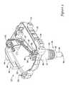
- FIG. 4is a perspective view, partially in cross-section, of an illustrative but non-limiting mounting bracket and temperature sensor assembly
- FIG. 4Ais a perspective view, partially in cross-section, of the illustrative but non-limiting mounting bracket of FIG. 4 , with the temperature sensor assembly not shown;
- FIG. 5is another perspective view of the illustrative but non-limiting mounting bracket of FIG. 3 ;
- FIG. 6is a top plan view of the illustrative but non-limiting mounting bracket of FIG. 3 ;
- FIG. 7is a side view of the illustrative but non-limiting mounting bracket of FIG. 3 ;
- FIG. 8is a block diagram of a controller that may be used with the water heater of FIG. 1 .
- FIG. 1provides a schematic view of an illustrative but non-limiting water heater 10 .
- Water heater 10includes a water tank 12 .
- the water tank 12may include an insulating layer (not explicitly shown) positioned about the water tank 12 to help reduce thermal losses from the water tank 12 .
- Cold waterenters water tank 12 through a cold water line 14 and is heated by a gas burner 24 .
- the water heater 10may include an electric heating element rather than a gas burner 24 .
- a power delivery unit(not shown) may be used to selectively apply power (i.e. current) to the electric heating element. In either case, the resulting heated water exits through a hot water line 16 .
- a gas control unit 18such as a gas valve regulates gas flow from a gas source 20 through a combustion gas line 22 and into gas burner 24 .
- a flue 26permits combustion byproducts to safely exit.
- water heater 10includes a temperature sensor 28 .
- temperature sensor 28may enter water tank 12 at a location laterally offset from gas control unit 18 .
- temperature sensor 28may instead be located behind gas control unit 18 , and in some cases, may be supported and retained by a common mounting bracket such as that described more fully below.
- water tank 12may include an aperture 30 that is sized and configured to accept temperature sensor 28 . This can be seen in FIG. 2 , in which certain elements of FIG. 1 have been removed for clarity.
- Aperture 30may include threads that are configured to accommodate corresponding matching threads on temperature sensor 28 .
- temperature sensor 28has a compression or frictional fit within aperture 30 .
- water tank 12may include a threaded spud (not explicitly shown) that is configured to receive temperature sensor 28 .
- FIG. 3is a perspective view of an illustrative but non-limiting mounting bracket 32 that may be used in conjunction with the water heater 10 .
- the mounting bracket 32may include a component retaining region 33 and a sensor portion 36 forming an elongated stem. Bracket 32 may be configured to retain a gas valve module and/or a water heater controller module (not explicitly shown) within component retaining region 33 , as well as a temperature sensor assembly 49 (see also FIG. 4 ) within elongated stem 36 .
- bracket 32includes a gas valve retaining portion 34 and a sensor portion 36 .
- Gas valve retaining portion 34may form at least a portion of a housing of a gas control unit, such as gas control unit 18 of FIG. 1 , but this is not required.
- elongated sensor portion 36may include a threaded portion 38 that can be used to secure bracket 32 to or within aperture 30 ( FIG. 2 ) of water heater spud.
- Bracket 32may be formed of any suitable material.
- bracket 32may include non-metallic materials such as a polymeric material, glass, ceramic, plastic, and the like.
- bracket 32may be manufactured as a single piece by injection molding a nylon material such Hylon®, available from Entec Polymers in Manchester, Tenn. The thermal conductivity of such non-metallic materials may be less than those of metallic materials, and as a result, may partially thermally isolate the temperature sensor assembly 49 from the water in the water tank 12 , but may be less expensive to produce than a metallic well. It is contemplated that in some cases, bracket 32 may not be formed entirely from the same material, or bracket 32 may not be formed as a single piece. As will be discussed in more detail with respect to FIG. 7 , bracket 32 may incorporate safety features to prevent injury from hot water in the event bracket 32 becomes broken or damaged after installation.
- Sensor portion 36 of the bracket 32may include an elongated stem extending from component retaining region 33 .
- Sensor portion 36may include an internal well 39 (shown in more detail in FIGS. 4 and 4A ) for receiving a temperature sensor assembly 49 .
- the elongated stem of sensor portion 36may include of several different regions.
- sensor portion 36may include a first portion 37 , a threaded region 38 extending around the exterior of the sensor portion 36 , a thread lead-in region 40 , and an enclosed distal end region 42 .
- Threaded region 38may be configured to threadably engage a threaded spud in the water tank 12 .
- Thread lead-in region 40may be disposed between the distal end region 42 and the threaded region, and may be configured to help guide the sensor portion 36 into the aperture 30 of the water tank 12 with proper alignment for the threaded region 38 to engage the threaded spud in the water tank 12 .
- the thread lead-in region 40may have zero draft for maximum effectiveness, but this is not required.
- distal end 42When threaded region 38 is engaged with the threaded water heater spud, distal end 42 may be disposed within water tank 12 . Distal end 42 may house a temperature sensor such that when the bracket 32 is engaged with the water tank 12 , the temperature sensor is in at least partial thermal contact with the water in the water tank 12 .
- distal end region 42may have a reduced cross-sectional area relative to remaining regions 37 , 38 and 40 of sensor portion 36 .
- the cross-sectional area of distal end 42may be the same as, or substantially the same as the remaining regions 37 , 38 and 40 of sensor portion 36 .
- distal end 42may include a cutting element 54 disposed at or near the tip.
- the cutting element 54may include a blade-like feature.
- Cutting element 54may be capable of puncturing and/or piercing a plastic sheet or barrier commonly wrapped around the water tank 12 of many water heaters during installation of the bracket 32 . It is contemplated that in some cases, the cutting element 54 may be omitted from the design.
- bracket 32may also include two (or more) bosses 44 on a first lateral side, and two (or more) bosses 44 on a second opposing lateral side. While bracket 32 is shown having four bosses 44 , it is contemplated that bracket 32 may have any number of bosses 44 as desired, for example, but not limited to, one, two, three, or more. Additionally, it is contemplated that bosses 44 may be disposed on fewer than, or more than, two lateral sides. Bosses 44 may provide, among other things, an area for torque to be applied directly to the bracket 32 during installation.
- an installation toolmay grip and apply torque to bosses 44 to threadably engage threaded region 38 of sensor portion 36 with the threaded water heater spud on a water tank 12 .
- bosses 44may further include a rib 46 disposed between adjacent bosses 44 . Rib(s) 46 may provide additional support to the bracket 32 , and may also help prevent an installation tool from contacting the component retaining region 33 of bracket 32 during installation.
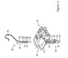
- FIG. 4is a perspective view, partially in cross-section, of an illustrative but non-limiting mounting bracket 32 and temperature sensor assembly 49 .
- the temperature sensor assembly 49is shown pulled out of the sensor region 36 and situated above the bracket 32 in an exploded view form. As can be seen, the sensor portion 36 may be configured to accommodate the temperature sensor assembly 49 .
- temperature sensor assembly 49includes one or more heat traps 58 that are attached to or otherwise secured to sensor assembly structure 50 , and may serve to help limit or at least partially limit heat flow out of the sensor portion 36 of the bracket 32 .
- Sensor assembly structure 50may further include one or more convolutions 61 .
- convolutions 61may apply a spring-like force that holds the temperatures sensor 56 in tight contact with the bottom of the internal well 39 . Convolutions 61 may also reduce the need to use a fastener to secure the temperature sensor assembly 49 .
- Temperature sensor assembly 49may be configured to accommodate a temperature sensor 56 .
- temperature sensor 56may be a single temperature sensor.
- temperature sensor 56may include multiple temperature sensors, which may provide a measure of redundancy and/or increased accuracy in a corresponding temperature measurement.
- the temperature sensor 56may include a thermopile or thermocouple.
- heat traps 58 and temperature sensor 56may be attached to a sensor assembly structure 50 . This may be accomplished by snap fits, frictional fits, glue, screws, rivets, or any other suitable attachment mechanism. In some instances, heat traps 58 may be integrally molded or otherwise formed as part of sensor assembly structure 50 . In some cases, the heat traps 58 may each include a slot 60 in order to accommodate and/or secure a wiring harness 68 for the temperature sensor 56 . Once heat traps 58 and temperature sensor 56 have been secured or otherwise attached to sensor assembly structure 50 , sensor assembly structure 50 may be inserted into a void 52 that is molded or otherwise formed within sensor portion 36 .
- sensor assembly structure 50may include one or more protrusions such as protrusion 62 that may help to locate sensor assembly structure 50 within void 52 and/or limit penetration of sensor assembly structure 50 into void 52 while allowing wiring harness 68 to pass without being pinched.
- the one or more protrusions 62may align the sensor assembly structure 50 with inwardly extending ribs 48 disposed on the inner walls of the sensor portion 36 and into the void.
- One or more protrusions 62 in cooperation with one or more ribs 48may, in some instances, help properly align and assemble the temperature sensor assembly 49 within the sensor portion 36 .
- One or more protrusions 62may also ensure that sensor assembly 49 is not installed in the wrong bracket.
- sensor 56may be disposed within an internal well 39 within the distal tip portion 42 of the sensor portion.
- FIG. 4Ais a perspective view, partially in cross-section, of the illustrative but non-limiting mounting bracket of FIG. 4 , with the temperature sensor assembly not shown.
- the void 52 within the sensor region 36may include inwardly extending ribs 48 .
- Ribs 48may extend any length along the void 52 , as desired. While ribs 48 are shown extending to a distal end of threaded region 38 , it is contemplated in some embodiments, ribs 48 may extend past threaded region 38 . In other embodiments, ribs 48 may terminate short of threaded region 38 , or at any point within threaded region 38 .
- sensor portion 36may include one or more slots 66 for receiving one or more protrusions such as protrusion 62 that may help locate temperature assembly structure 50 within void 52 and/or limit penetration of temperature assembly structure 50 into void 52 .
- FIG. 5is another perspective view of the illustrative but non-limiting mounting bracket of FIG. 3 .
- the bracket 32includes a number of outer ribs 64 extending along the back of component retaining region 33 of bracket 32 and to the first region 37 of sensor portion 36 .
- not all ribs 64have been identified with a reference numeral.
- outer ribs 64may not extend all the way to sensor portion 36 , while in other cases, ribs 64 may extend further along sensor portion 36 towards threaded region 38 .
- the number of ribs 64may vary as desired depending on the application.
- bracket 32may have zero ribs 64 , as few as one rib 64 , more than 14 ribs, or any other number of ribs 64 as desired. As shown, the ribs 64 may radiate out from the elongated stem of the sensor region 36 , but this is not required.
- the ribs 64may provide additional strength to bracket 32 .
- the ribs 64may be sufficient for the bracket 32 to withstand a 500 pound-force (1 bf) static vertical load (roughly equivalent to a 300 lb person stepping on the installed bracket).
- bracket 32may resist accidental breakage.
- bracket 32may have other safety features to help prevent a user from being exposed to hot water from the water tank 12 , as will be discussed in more detail below with respect to FIG. 7 .
- FIG. 6is a top plan view of the illustrative but non-limiting mounting bracket 32 of FIG. 3 , with the temperature sensor assembly 49 positioned within void 52 such that temperature sensor 56 is disposed within the internal well 39 .
- one or more protrusions 62may be positioned between internal ribs 48 or within slot 66 .
- Internal ribs 48may be radially spaced within void 52 . While ribs 48 are illustrated as equally spaced around the circumference of void 52 , it is contemplated that internal ribs 48 may be spaced at any distance desired, or may not be present at all.
- Wiring harness 68may be configured to extend from temperature sensor assembly 49 and to a gas control unit, such as the gas control unit 18 illustrated in FIG. 1 .
- Component retaining region 33may include retaining elements 67 for retaining wiring harness 68 .
- Retaining elements 67may be molded in such a way as to allow the use of an optical sensor in production to ensure that the wiring harness 68 and/or sensor wires are properly installed.
- bracket 32may be molded such that an opening is present behind retaining elements 67 .
- component retaining region 33may also include retaining elements for retaining a water heater controller module and/or gas valve module, if desired.
- FIG. 7is a side view of the illustrative but non-limiting mounting bracket of FIG. 3 , with the temperature sensor assembly 49 disposed within void 52 (not explicitly shown).
- Threaded region 38may be configured to provide additional safety features to bracket 32 , if desired.
- threaded region 38may include a plurality of threads 70 spaced a distance apart. Geometric dimensioning and tolerancing may be used to control the angle and roundness of the threads 70 .
- threads 70may be spaced such that there are 13.9-14.0 threads per inch. In other embodiments, it is contemplated that there may be more or fewer threads per inch.
- threads 70may be spaced to ensure that the material in the threads 70 is in compression, and not in tension. This may increase the strength of the threaded region 38 when torque is being applied during installation of the bracket 32 , as well as increasing the strength to support a vertical load. In some cases, threaded region 38 may be able to withstand 75 foot-pounds (ft-lbs), or more, of torque. In some embodiments, the root 72 of threads 70 may be rounded to relieve stress in the threads 70 . A round root 72 may increase the strength during application of torque as well as for a vertical load.
- bracket 32may break in a sudden manner resulting in a brittle fracture.
- a suitable material for creating such a breakis Entec Hylon, however, other materials may be used. The stress from such an event may be concentrated in the last thread 70 that engages the water heater spud. A brittle material may result in a clean break at or near the outside edge of the water heater spud such that the portion of the sensor portion 36 that has been threadably engaged with the water heater spud remain positioned within the water heater spud.
- the distal portion 42 and part of the threaded region 38 of the sensor portion 36may remain disposed within the water tank 12 and water heater spud. This may help prevent significant leakage of hot water from the water heater.
- the internal ribs 48(see FIG. 6 ) disposed within the void 52 may be used to axially align a removal tool, for example, a TORX bit, and to provide a surface to which torque may be applied to remove the broken off portion of the bracket 32 from the water heater. If ribs 48 are not present in the remaining portion of the sensor portion 36 , a removal tool having sharp blades may dig into the interior surface of the internal well 39 to remove the broken off portion.
- gas control unit 18may include a controller.
- FIG. 8is a block diagram of such a controller 74 .
- the controller 74may be considered as being a portion of gas control unit 18 , or separate from gas control unit 18 .
- Controller 74may have several modules.
- controller 74may have an INPUT/OUTPUT block 76 that accepts signals from temperature sensor 28 ( FIG. 1 ) and/or temperature sensor assembly 49 ( FIG. 3 ). If water heater 10 is in communication with an external thermostat or other HVAC controller, INPUT/OUTPUT block 76 may accommodate externally-derived control signals, and/or provide status and/or other information, as desired. In some cases, INPUT/OUTPUT block 76 may also provide appropriate output command signals to an electrically controlled gas valve (not illustrated) within gas control unit 18 .
- controller 74may include a microprocessor 78 that may be configured to accept appropriate signals from INPUT/OUTPUT block 76 , and to determine appropriate output signals that can be outputted via INPUT/OUTPUT block 76 , such as to other components within gas control unit 18 ( FIG. 1 ) and/or to an external thermostat or other HVAC controller.
- Microprocessor 78may be programmed to accept a temperature signal from temperature sensing assembly 32 ( FIG. 3 ), and to calculate or otherwise determine a command temperature that alters the temperature value received from the temperature sensing assembly 32 in order to account or compensate for temperature differentials and/or thermal lag caused by the partial thermal isolation (if present) of the temperature sensor 56 from the water in the water tank 12 .
- microprocessor 78may also include memory and/or other components.
- memory and/or other componentsare also discussed in co-pending U.S. patent application Ser. No. 12/255,592, filed Oct. 21, 2008, and entitled “WATER HEATER WITH PARTIALLY THERMALLY ISOLATED TEMPERATURE SENSOR”, the entirety of which is incorporated herein by reference.
Landscapes
- Engineering & Computer Science (AREA)
- Physics & Mathematics (AREA)
- Thermal Sciences (AREA)
- Chemical & Material Sciences (AREA)
- Combustion & Propulsion (AREA)
- Mechanical Engineering (AREA)
- General Engineering & Computer Science (AREA)
- Computer Hardware Design (AREA)
- Heat-Pump Type And Storage Water Heaters (AREA)
Abstract
Description
Claims (20)
Priority Applications (2)
| Application Number | Priority Date | Filing Date | Title |
|---|---|---|---|
| US12/642,449US8245987B2 (en) | 2009-12-18 | 2009-12-18 | Mounting bracket for use with a water heater |
| US12/794,593US9249986B2 (en) | 2009-12-18 | 2010-06-04 | Mounting bracket for use with a water heater |
Applications Claiming Priority (1)
| Application Number | Priority Date | Filing Date | Title |
|---|---|---|---|
| US12/642,449US8245987B2 (en) | 2009-12-18 | 2009-12-18 | Mounting bracket for use with a water heater |
Related Child Applications (1)
| Application Number | Title | Priority Date | Filing Date |
|---|---|---|---|
| US12/794,593Continuation-In-PartUS9249986B2 (en) | 2009-12-18 | 2010-06-04 | Mounting bracket for use with a water heater |
Publications (2)
| Publication Number | Publication Date |
|---|---|
| US20110147549A1 US20110147549A1 (en) | 2011-06-23 |
| US8245987B2true US8245987B2 (en) | 2012-08-21 |
Family
ID=44149716
Family Applications (1)
| Application Number | Title | Priority Date | Filing Date |
|---|---|---|---|
| US12/642,449Active2030-04-22US8245987B2 (en) | 2009-12-18 | 2009-12-18 | Mounting bracket for use with a water heater |
Country Status (1)
| Country | Link |
|---|---|
| US (1) | US8245987B2 (en) |
Cited By (17)
| Publication number | Priority date | Publication date | Assignee | Title |
|---|---|---|---|---|
| US20120000902A1 (en)* | 2010-06-30 | 2012-01-05 | Daniel Lako | Device for Regulated Water Heating Using the Energy Gained By Photovoltaic Cells |
| WO2015103669A1 (en)* | 2014-01-13 | 2015-07-16 | Dux Manufacturing Limited | A sensor mounting device and a related water heater and mounting method |
| US9249987B2 (en) | 2013-01-30 | 2016-02-02 | Honeywell International Inc. | Mounting bracket for use with a water heater |
| US9799201B2 (en) | 2015-03-05 | 2017-10-24 | Honeywell International Inc. | Water heater leak detection system |
| US9885484B2 (en) | 2013-01-23 | 2018-02-06 | Honeywell International Inc. | Multi-tank water heater systems |
| US9920930B2 (en) | 2015-04-17 | 2018-03-20 | Honeywell International Inc. | Thermopile assembly with heat sink |
| US10088852B2 (en) | 2013-01-23 | 2018-10-02 | Honeywell International Inc. | Multi-tank water heater systems |
| US10119726B2 (en) | 2016-10-06 | 2018-11-06 | Honeywell International Inc. | Water heater status monitoring system |
| US10132510B2 (en) | 2015-12-09 | 2018-11-20 | Honeywell International Inc. | System and approach for water heater comfort and efficiency improvement |
| US10670302B2 (en) | 2014-03-25 | 2020-06-02 | Ademco Inc. | Pilot light control for an appliance |
| US10731895B2 (en) | 2018-01-04 | 2020-08-04 | Ademco Inc. | Mounting adaptor for mounting a sensor assembly to a water heater tank |
| US10969143B2 (en) | 2019-06-06 | 2021-04-06 | Ademco Inc. | Method for detecting a non-closing water heater main gas valve |
| US11236930B2 (en) | 2018-05-01 | 2022-02-01 | Ademco Inc. | Method and system for controlling an intermittent pilot water heater system |
| US11592852B2 (en) | 2014-03-25 | 2023-02-28 | Ademco Inc. | System for communication, optimization and demand control for an appliance |
| US11656000B2 (en) | 2019-08-14 | 2023-05-23 | Ademco Inc. | Burner control system |
| US11739982B2 (en) | 2019-08-14 | 2023-08-29 | Ademco Inc. | Control system for an intermittent pilot water heater |
| US12392525B2 (en) | 2020-10-09 | 2025-08-19 | Rheem Manufacturing Company | Electronic temperature limiting control |
Families Citing this family (4)
| Publication number | Priority date | Publication date | Assignee | Title |
|---|---|---|---|---|
| US8337081B1 (en)* | 2012-01-09 | 2012-12-25 | Honeywell International Inc. | Sensor assembly for mounting a temperature sensor to a tank |
| US9303897B2 (en)* | 2012-06-12 | 2016-04-05 | Emerson Electric Co. | Compensating for sensor thermal lag |
| CN109579313A (en)* | 2018-09-27 | 2019-04-05 | 中山市思源电器有限公司 | Mounting bracket of water heater |
| JP7272836B2 (en)* | 2019-03-19 | 2023-05-12 | 住友重機械工業株式会社 | Sensor, sensor fixing structure |
Citations (80)
| Publication number | Priority date | Publication date | Assignee | Title |
|---|---|---|---|---|
| US3847350A (en) | 1973-01-02 | 1974-11-12 | G Thompson | Vehicle heating unit |
| US3849350A (en) | 1973-06-06 | 1974-11-19 | Atomic Energy Commission | Process of making low density syntactic foams |
| US4324944A (en) | 1979-12-04 | 1982-04-13 | Siemens Aktiengesellschaft | Arrangement for controlling the electrodes of an arc furnace |
| USRE30936E (en) | 1978-02-06 | 1982-05-18 | Scotty Vent Dampers, Inc. | Safety control for furnace burner |
| US4333002A (en) | 1980-09-02 | 1982-06-01 | A. O. Smith Corporation | Multiple device control apparatus |
| US4467178A (en) | 1982-03-26 | 1984-08-21 | Swindle Elro M | Control system for regulating water heater operation in accordance with anticipated demand |
| US4508261A (en) | 1982-01-28 | 1985-04-02 | Gerald Blank | Hot water control and management system |
| US4511790A (en) | 1982-09-30 | 1985-04-16 | A. O. Smith Corporation | Multiple load control apparatus having load equalization |
| US4568821A (en) | 1982-06-22 | 1986-02-04 | Pba Inc. | Remote water heater controller |
| US4588875A (en) | 1982-09-30 | 1986-05-13 | A. O. Smith Corporation | Multiple load control apparatus with load equalization |
| US4692598A (en) | 1982-10-16 | 1987-09-08 | Yamato Scientific Co., Ltd. | Temperature controller system |
| US4696639A (en) | 1986-11-06 | 1987-09-29 | Honeywell Inc. | Self-energizing burner control system for a fuel burner |
| US4734658A (en) | 1987-08-14 | 1988-03-29 | Honeywell Inc. | Low voltage driven oscillator circuit |
| US4742210A (en) | 1985-10-23 | 1988-05-03 | Sanyo Electric Co., Ltd. | Electric heating apparatus having a universal electrical connector |
| US4770629A (en) | 1987-03-11 | 1988-09-13 | Honeywell Inc. | Status indicator for self-energizing burner control system |
| US4834284A (en) | 1988-06-29 | 1989-05-30 | Fluidmaster, Inc. | Hot water control |
| GB2211331A (en) | 1987-10-16 | 1989-06-28 | Smith Corp A O | Water heater diagnostic apparatus |
| EP0356609A1 (en) | 1988-08-31 | 1990-03-07 | Landis & Gyr Business Support AG | Set-point adjuster for a domestic hot water storage regulator |
| US4984981A (en) | 1989-06-02 | 1991-01-15 | A. O. Smith Corporation | Heater with flame powered logic supply circuit |
| US4986468A (en) | 1989-08-29 | 1991-01-22 | A.O. Smith Corporation | Test circuit for system monitoring apparatus |
| US5007156A (en) | 1988-06-30 | 1991-04-16 | General Electric Company | Method of selectively connecting a set of winding means for a dynamoelectric machine into at least two different electrical configurations |
| US5103078A (en) | 1990-02-01 | 1992-04-07 | Boykin T Brooks | Programmable hot water heater control method |
| US5442157A (en) | 1992-11-06 | 1995-08-15 | Water Heater Innovations, Inc. | Electronic temperature controller for water heaters |
| EP0699316A1 (en) | 1993-05-17 | 1996-03-06 | Ea Technology Limited | Heating control apparatus |
| JPH08264469A (en) | 1995-03-24 | 1996-10-11 | Kokusai Electric Co Ltd | Electric furnace temperature control method |
| US5622200A (en) | 1994-04-14 | 1997-04-22 | Mertik Maxitrol Gmbh & Co., Kg | Thermo-electric safety igniter with reignition lock |
| US5660328A (en) | 1996-01-26 | 1997-08-26 | Robertshaw Controls Company | Water heater control |
| US5779143A (en) | 1997-02-13 | 1998-07-14 | Erie Manufacturing Company | Electronic boiler control |
| US5797358A (en) | 1996-07-08 | 1998-08-25 | Aos Holding Company | Control system for a water heater |
| US5896089A (en) | 1997-08-29 | 1999-04-20 | Bowles; Cleveland L. | Dual carbon monoxide detection system with gas cut off and alarm capabilities |
| US5968393A (en) | 1995-09-12 | 1999-10-19 | Demaline; John Tracey | Hot water controller |
| US5975884A (en) | 1997-10-24 | 1999-11-02 | H. Barry Bone | Stand-alone device for igniting, regulating and operating gas appliances |
| US6053130A (en) | 1998-06-04 | 2000-04-25 | American Water Heater Company | Power vent water heater with electronic control system |
| US6059195A (en) | 1998-01-23 | 2000-05-09 | Tridelta Industries, Inc. | Integrated appliance control system |
| US6069998A (en) | 1998-09-04 | 2000-05-30 | Emerson Electric Company | Integral water heater and water temperature sensor |
| US6075923A (en) | 1999-01-15 | 2000-06-13 | Wu; Ya-Ching | Self-compensatory water heater sensitively responsive to temperature variations |
| US6208806B1 (en) | 1998-06-24 | 2001-03-27 | Aquabeat Pty Ltd. | Electric water heater control |
| US6212894B1 (en) | 1996-03-29 | 2001-04-10 | Waterfurnace International Inc. | Microprocessor control for a heat pump water heater |
| US6261087B1 (en) | 1999-12-02 | 2001-07-17 | Honeywell International Inc. | Pilot flame powered burner controller with remote control operation |
| US6271505B1 (en) | 2000-02-16 | 2001-08-07 | Rheem Manufacturing Company | Field conversion electric water heater |
| US6293471B1 (en) | 2000-04-27 | 2001-09-25 | Daniel R. Stettin | Heater control device and method to save energy |
| US6350967B1 (en) | 2000-05-24 | 2002-02-26 | American Water Heater Company | Energy saving water heater control |
| US6363218B1 (en) | 1999-01-15 | 2002-03-26 | Ail Research, Inc. | Liquid heater load control |
| US6371057B1 (en)* | 1999-12-21 | 2002-04-16 | Srp 68/Pty. Ltd. | Adjustable mount for a gas control valve of a water heater |
| US6375087B1 (en) | 2000-06-14 | 2002-04-23 | International Business Machines Corporation | Method and apparatus for self-programmable temperature and usage control for hot water heaters |
| USRE37745E1 (en) | 1996-07-08 | 2002-06-18 | Aos Holding Company | Control system for a water heater |
| US6553946B1 (en)* | 2000-06-09 | 2003-04-29 | Roberrshaw Controls Company | Multi-function water heater control device |
| US6560409B2 (en) | 2000-01-03 | 2003-05-06 | Honeywell International Inc. | Hot water heater stacking reduction control |
| US6633726B2 (en) | 1999-07-27 | 2003-10-14 | Kenneth A. Bradenbaugh | Method of controlling the temperature of water in a water heater |
| US20040042772A1 (en) | 2000-12-18 | 2004-03-04 | Whitford Geoffrey M. | Thermostat system to provide adaptive control of water temperature |
| US6701874B1 (en) | 2003-03-05 | 2004-03-09 | Honeywell International Inc. | Method and apparatus for thermal powered control |
| US6732677B2 (en)* | 2002-10-15 | 2004-05-11 | Emerson Electric Co. | Bracket for water heater |
| US20040267385A1 (en) | 2003-06-27 | 2004-12-30 | Hx Lifespace, Inc. | Building automation system |
| US6861621B2 (en) | 2002-03-22 | 2005-03-01 | Whirlpool Corporation | Demand side management of water heater systems |
| US20050077368A1 (en) | 2003-03-05 | 2005-04-14 | Honeywell International Inc. | Senor diagnostic for determining water heater health status |
| US6880493B2 (en) | 1992-03-23 | 2005-04-19 | Todd W. Clifford | Gas water heater and method of operation |
| US20050147402A1 (en) | 2003-02-19 | 2005-07-07 | Apcom, Inc. | Water heater and method of operating the same |
| US20050150967A1 (en) | 2004-01-08 | 2005-07-14 | Maple Chase Company | System and method for reducing energy consumption by a water heater and thermostat for use therewith |
| US6934862B2 (en) | 2000-01-07 | 2005-08-23 | Robertshaw Controls Company | Appliance retrofit monitoring device with a memory storing an electronic signature |
| US6936798B2 (en) | 2000-07-27 | 2005-08-30 | Joseph Tiran | Programmable domestic water heating system |
| US6955301B2 (en) | 2003-03-05 | 2005-10-18 | Honeywell International, Inc. | Water heater and control |
| US6959876B2 (en) | 2003-04-25 | 2005-11-01 | Honeywell International Inc. | Method and apparatus for safety switch |
| US6973819B2 (en)* | 2003-11-01 | 2005-12-13 | Honeywell International Inc. | Differential compensated vapor sensor |
| US7088238B2 (en) | 2002-12-11 | 2006-08-08 | Broadcom, Inc. | Access, monitoring, and control of appliances via a media processing system |
| US7117825B2 (en) | 2004-06-30 | 2006-10-10 | Synapse, Inc. | System and method for preventing overheating of water within a water heater tank |
| US20060243816A1 (en) | 2005-04-19 | 2006-11-02 | Robert Teti | Water heater control |
| US7137373B2 (en)* | 2005-01-31 | 2006-11-21 | International Engine Intellectual Property Company, Llc | Valve lifter guide |
| US7162150B1 (en)* | 2005-11-23 | 2007-01-09 | Therm-O-Disc, Incorporated | Thermistor sensor probe with bimetal high limit control for electric water heater control |
| US20070023333A1 (en) | 2005-07-29 | 2007-02-01 | Pti Technologies, Inc. | Missing element indicator |
| US7221862B1 (en) | 2005-12-08 | 2007-05-22 | Therm-O-Disc, Incorporated | Control and method for operating an electric water heater |
| US7252502B2 (en) | 2004-01-27 | 2007-08-07 | Honeywell International Inc. | Method and system for combined standing pilot safety and temperature setting |
| US20070191994A1 (en) | 2001-11-15 | 2007-08-16 | Patterson Wade C | System and method for controlling temperature of a liquid residing within a tank |
| US20070246551A1 (en) | 2004-08-26 | 2007-10-25 | Phillips Terry G | Modular control system and method for water heaters |
| US20070295823A1 (en) | 2006-05-26 | 2007-12-27 | Rinnai Corporation | Radio communication system of water heater |
| US7317265B2 (en) | 2003-03-05 | 2008-01-08 | Honeywell International Inc. | Method and apparatus for power management |
| JP2008008548A (en) | 2006-06-29 | 2008-01-17 | Hitachi Appliances Inc | Electric water heater |
| US20080023564A1 (en) | 2006-04-28 | 2008-01-31 | Robert Charles Hall | Method And Apparatus For Centrally Controlling A Hybrid Furnace, Heater, And Boiler System Installation |
| US20080188995A1 (en) | 2007-02-06 | 2008-08-07 | Rheem Manufacturing Company | Water heater monitor/diagnostic display apparatus |
| US20100095906A1 (en)* | 2008-10-21 | 2010-04-22 | Honeywell International Inc. | Water heater with partially thermally isolated temperature sensor |
| US20100133258A1 (en)* | 2002-09-23 | 2010-06-03 | Giovanni Fima | Systems & Methods For Monitoring And Controlling Water Consumption |
Family Cites Families (3)
| Publication number | Priority date | Publication date | Assignee | Title |
|---|---|---|---|---|
| US30936A (en)* | 1860-12-18 | slocum | ||
| US37745A (en)* | 1863-02-24 | Improvement in apparatus for cooking with gas | ||
| US6582921B2 (en)* | 1996-07-29 | 2003-06-24 | Nanosphere, Inc. | Nanoparticles having oligonucleotides attached thereto and uses thereof |
- 2009
- 2009-12-18USUS12/642,449patent/US8245987B2/enactiveActive
Patent Citations (83)
| Publication number | Priority date | Publication date | Assignee | Title |
|---|---|---|---|---|
| US3847350A (en) | 1973-01-02 | 1974-11-12 | G Thompson | Vehicle heating unit |
| US3849350A (en) | 1973-06-06 | 1974-11-19 | Atomic Energy Commission | Process of making low density syntactic foams |
| USRE30936E (en) | 1978-02-06 | 1982-05-18 | Scotty Vent Dampers, Inc. | Safety control for furnace burner |
| US4324944A (en) | 1979-12-04 | 1982-04-13 | Siemens Aktiengesellschaft | Arrangement for controlling the electrodes of an arc furnace |
| US4333002A (en) | 1980-09-02 | 1982-06-01 | A. O. Smith Corporation | Multiple device control apparatus |
| US4508261A (en) | 1982-01-28 | 1985-04-02 | Gerald Blank | Hot water control and management system |
| US4467178A (en) | 1982-03-26 | 1984-08-21 | Swindle Elro M | Control system for regulating water heater operation in accordance with anticipated demand |
| US4568821A (en) | 1982-06-22 | 1986-02-04 | Pba Inc. | Remote water heater controller |
| US4511790A (en) | 1982-09-30 | 1985-04-16 | A. O. Smith Corporation | Multiple load control apparatus having load equalization |
| US4588875A (en) | 1982-09-30 | 1986-05-13 | A. O. Smith Corporation | Multiple load control apparatus with load equalization |
| US4692598A (en) | 1982-10-16 | 1987-09-08 | Yamato Scientific Co., Ltd. | Temperature controller system |
| US4742210A (en) | 1985-10-23 | 1988-05-03 | Sanyo Electric Co., Ltd. | Electric heating apparatus having a universal electrical connector |
| US4696639A (en) | 1986-11-06 | 1987-09-29 | Honeywell Inc. | Self-energizing burner control system for a fuel burner |
| US4770629A (en) | 1987-03-11 | 1988-09-13 | Honeywell Inc. | Status indicator for self-energizing burner control system |
| US4734658A (en) | 1987-08-14 | 1988-03-29 | Honeywell Inc. | Low voltage driven oscillator circuit |
| GB2211331A (en) | 1987-10-16 | 1989-06-28 | Smith Corp A O | Water heater diagnostic apparatus |
| US4834284A (en) | 1988-06-29 | 1989-05-30 | Fluidmaster, Inc. | Hot water control |
| US5007156A (en) | 1988-06-30 | 1991-04-16 | General Electric Company | Method of selectively connecting a set of winding means for a dynamoelectric machine into at least two different electrical configurations |
| EP0356609A1 (en) | 1988-08-31 | 1990-03-07 | Landis & Gyr Business Support AG | Set-point adjuster for a domestic hot water storage regulator |
| US4984981A (en) | 1989-06-02 | 1991-01-15 | A. O. Smith Corporation | Heater with flame powered logic supply circuit |
| US4986468A (en) | 1989-08-29 | 1991-01-22 | A.O. Smith Corporation | Test circuit for system monitoring apparatus |
| US5103078A (en) | 1990-02-01 | 1992-04-07 | Boykin T Brooks | Programmable hot water heater control method |
| US6880493B2 (en) | 1992-03-23 | 2005-04-19 | Todd W. Clifford | Gas water heater and method of operation |
| US5442157A (en) | 1992-11-06 | 1995-08-15 | Water Heater Innovations, Inc. | Electronic temperature controller for water heaters |
| EP0699316A1 (en) | 1993-05-17 | 1996-03-06 | Ea Technology Limited | Heating control apparatus |
| US5622200A (en) | 1994-04-14 | 1997-04-22 | Mertik Maxitrol Gmbh & Co., Kg | Thermo-electric safety igniter with reignition lock |
| JPH08264469A (en) | 1995-03-24 | 1996-10-11 | Kokusai Electric Co Ltd | Electric furnace temperature control method |
| US5968393A (en) | 1995-09-12 | 1999-10-19 | Demaline; John Tracey | Hot water controller |
| US5660328A (en) | 1996-01-26 | 1997-08-26 | Robertshaw Controls Company | Water heater control |
| US6212894B1 (en) | 1996-03-29 | 2001-04-10 | Waterfurnace International Inc. | Microprocessor control for a heat pump water heater |
| US5797358A (en) | 1996-07-08 | 1998-08-25 | Aos Holding Company | Control system for a water heater |
| USRE37745E1 (en) | 1996-07-08 | 2002-06-18 | Aos Holding Company | Control system for a water heater |
| US5779143A (en) | 1997-02-13 | 1998-07-14 | Erie Manufacturing Company | Electronic boiler control |
| US5896089A (en) | 1997-08-29 | 1999-04-20 | Bowles; Cleveland L. | Dual carbon monoxide detection system with gas cut off and alarm capabilities |
| US5975884A (en) | 1997-10-24 | 1999-11-02 | H. Barry Bone | Stand-alone device for igniting, regulating and operating gas appliances |
| US6059195A (en) | 1998-01-23 | 2000-05-09 | Tridelta Industries, Inc. | Integrated appliance control system |
| US6053130A (en) | 1998-06-04 | 2000-04-25 | American Water Heater Company | Power vent water heater with electronic control system |
| US6208806B1 (en) | 1998-06-24 | 2001-03-27 | Aquabeat Pty Ltd. | Electric water heater control |
| US6069998A (en) | 1998-09-04 | 2000-05-30 | Emerson Electric Company | Integral water heater and water temperature sensor |
| US6075923A (en) | 1999-01-15 | 2000-06-13 | Wu; Ya-Ching | Self-compensatory water heater sensitively responsive to temperature variations |
| US6363218B1 (en) | 1999-01-15 | 2002-03-26 | Ail Research, Inc. | Liquid heater load control |
| US6633726B2 (en) | 1999-07-27 | 2003-10-14 | Kenneth A. Bradenbaugh | Method of controlling the temperature of water in a water heater |
| US6795644B2 (en) | 1999-07-27 | 2004-09-21 | Kenneth A. Bradenbaugh | Water heater |
| US6261087B1 (en) | 1999-12-02 | 2001-07-17 | Honeywell International Inc. | Pilot flame powered burner controller with remote control operation |
| US6371057B1 (en)* | 1999-12-21 | 2002-04-16 | Srp 68/Pty. Ltd. | Adjustable mount for a gas control valve of a water heater |
| US6560409B2 (en) | 2000-01-03 | 2003-05-06 | Honeywell International Inc. | Hot water heater stacking reduction control |
| US6934862B2 (en) | 2000-01-07 | 2005-08-23 | Robertshaw Controls Company | Appliance retrofit monitoring device with a memory storing an electronic signature |
| US6271505B1 (en) | 2000-02-16 | 2001-08-07 | Rheem Manufacturing Company | Field conversion electric water heater |
| US6293471B1 (en) | 2000-04-27 | 2001-09-25 | Daniel R. Stettin | Heater control device and method to save energy |
| US6350967B1 (en) | 2000-05-24 | 2002-02-26 | American Water Heater Company | Energy saving water heater control |
| US6553946B1 (en)* | 2000-06-09 | 2003-04-29 | Roberrshaw Controls Company | Multi-function water heater control device |
| US6375087B1 (en) | 2000-06-14 | 2002-04-23 | International Business Machines Corporation | Method and apparatus for self-programmable temperature and usage control for hot water heaters |
| US6936798B2 (en) | 2000-07-27 | 2005-08-30 | Joseph Tiran | Programmable domestic water heating system |
| US20040042772A1 (en) | 2000-12-18 | 2004-03-04 | Whitford Geoffrey M. | Thermostat system to provide adaptive control of water temperature |
| US20070191994A1 (en) | 2001-11-15 | 2007-08-16 | Patterson Wade C | System and method for controlling temperature of a liquid residing within a tank |
| US6861621B2 (en) | 2002-03-22 | 2005-03-01 | Whirlpool Corporation | Demand side management of water heater systems |
| US20100133258A1 (en)* | 2002-09-23 | 2010-06-03 | Giovanni Fima | Systems & Methods For Monitoring And Controlling Water Consumption |
| US6732677B2 (en)* | 2002-10-15 | 2004-05-11 | Emerson Electric Co. | Bracket for water heater |
| US7088238B2 (en) | 2002-12-11 | 2006-08-08 | Broadcom, Inc. | Access, monitoring, and control of appliances via a media processing system |
| US20050147402A1 (en) | 2003-02-19 | 2005-07-07 | Apcom, Inc. | Water heater and method of operating the same |
| US20050147401A1 (en) | 2003-02-19 | 2005-07-07 | Apcom, Inc. | Water heater and method of operating the same |
| US6955301B2 (en) | 2003-03-05 | 2005-10-18 | Honeywell International, Inc. | Water heater and control |
| US20050077368A1 (en) | 2003-03-05 | 2005-04-14 | Honeywell International Inc. | Senor diagnostic for determining water heater health status |
| US6701874B1 (en) | 2003-03-05 | 2004-03-09 | Honeywell International Inc. | Method and apparatus for thermal powered control |
| US7317265B2 (en) | 2003-03-05 | 2008-01-08 | Honeywell International Inc. | Method and apparatus for power management |
| US6959876B2 (en) | 2003-04-25 | 2005-11-01 | Honeywell International Inc. | Method and apparatus for safety switch |
| US20040267385A1 (en) | 2003-06-27 | 2004-12-30 | Hx Lifespace, Inc. | Building automation system |
| US6973819B2 (en)* | 2003-11-01 | 2005-12-13 | Honeywell International Inc. | Differential compensated vapor sensor |
| US20050150967A1 (en) | 2004-01-08 | 2005-07-14 | Maple Chase Company | System and method for reducing energy consumption by a water heater and thermostat for use therewith |
| US7252502B2 (en) | 2004-01-27 | 2007-08-07 | Honeywell International Inc. | Method and system for combined standing pilot safety and temperature setting |
| US7117825B2 (en) | 2004-06-30 | 2006-10-10 | Synapse, Inc. | System and method for preventing overheating of water within a water heater tank |
| US20070034169A1 (en) | 2004-06-30 | 2007-02-15 | Phillips Terry G | System and method for preventing overheating of water within a water heater tank |
| US20070246551A1 (en) | 2004-08-26 | 2007-10-25 | Phillips Terry G | Modular control system and method for water heaters |
| US7137373B2 (en)* | 2005-01-31 | 2006-11-21 | International Engine Intellectual Property Company, Llc | Valve lifter guide |
| US20060243816A1 (en) | 2005-04-19 | 2006-11-02 | Robert Teti | Water heater control |
| US20070023333A1 (en) | 2005-07-29 | 2007-02-01 | Pti Technologies, Inc. | Missing element indicator |
| US7162150B1 (en)* | 2005-11-23 | 2007-01-09 | Therm-O-Disc, Incorporated | Thermistor sensor probe with bimetal high limit control for electric water heater control |
| US7221862B1 (en) | 2005-12-08 | 2007-05-22 | Therm-O-Disc, Incorporated | Control and method for operating an electric water heater |
| US20080023564A1 (en) | 2006-04-28 | 2008-01-31 | Robert Charles Hall | Method And Apparatus For Centrally Controlling A Hybrid Furnace, Heater, And Boiler System Installation |
| US20070295823A1 (en) | 2006-05-26 | 2007-12-27 | Rinnai Corporation | Radio communication system of water heater |
| JP2008008548A (en) | 2006-06-29 | 2008-01-17 | Hitachi Appliances Inc | Electric water heater |
| US20080188995A1 (en) | 2007-02-06 | 2008-08-07 | Rheem Manufacturing Company | Water heater monitor/diagnostic display apparatus |
| US20100095906A1 (en)* | 2008-10-21 | 2010-04-22 | Honeywell International Inc. | Water heater with partially thermally isolated temperature sensor |
Cited By (23)
| Publication number | Priority date | Publication date | Assignee | Title |
|---|---|---|---|---|
| US8536495B2 (en)* | 2010-06-30 | 2013-09-17 | Daniel Lako | Device for regulated water heating using the energy gained by photovoltaic cells |
| US20120000902A1 (en)* | 2010-06-30 | 2012-01-05 | Daniel Lako | Device for Regulated Water Heating Using the Energy Gained By Photovoltaic Cells |
| US10088852B2 (en) | 2013-01-23 | 2018-10-02 | Honeywell International Inc. | Multi-tank water heater systems |
| US9885484B2 (en) | 2013-01-23 | 2018-02-06 | Honeywell International Inc. | Multi-tank water heater systems |
| US9249987B2 (en) | 2013-01-30 | 2016-02-02 | Honeywell International Inc. | Mounting bracket for use with a water heater |
| WO2015103669A1 (en)* | 2014-01-13 | 2015-07-16 | Dux Manufacturing Limited | A sensor mounting device and a related water heater and mounting method |
| US11592852B2 (en) | 2014-03-25 | 2023-02-28 | Ademco Inc. | System for communication, optimization and demand control for an appliance |
| US10670302B2 (en) | 2014-03-25 | 2020-06-02 | Ademco Inc. | Pilot light control for an appliance |
| US10049555B2 (en) | 2015-03-05 | 2018-08-14 | Honeywell International Inc. | Water heater leak detection system |
| US9799201B2 (en) | 2015-03-05 | 2017-10-24 | Honeywell International Inc. | Water heater leak detection system |
| US10692351B2 (en) | 2015-03-05 | 2020-06-23 | Ademco Inc. | Water heater leak detection system |
| US9920930B2 (en) | 2015-04-17 | 2018-03-20 | Honeywell International Inc. | Thermopile assembly with heat sink |
| US10738998B2 (en) | 2015-04-17 | 2020-08-11 | Ademco Inc. | Thermophile assembly with heat sink |
| US10132510B2 (en) | 2015-12-09 | 2018-11-20 | Honeywell International Inc. | System and approach for water heater comfort and efficiency improvement |
| US10989421B2 (en) | 2015-12-09 | 2021-04-27 | Ademco Inc. | System and approach for water heater comfort and efficiency improvement |
| US10119726B2 (en) | 2016-10-06 | 2018-11-06 | Honeywell International Inc. | Water heater status monitoring system |
| US10731895B2 (en) | 2018-01-04 | 2020-08-04 | Ademco Inc. | Mounting adaptor for mounting a sensor assembly to a water heater tank |
| US11236930B2 (en) | 2018-05-01 | 2022-02-01 | Ademco Inc. | Method and system for controlling an intermittent pilot water heater system |
| US11719467B2 (en) | 2018-05-01 | 2023-08-08 | Ademco Inc. | Method and system for controlling an intermittent pilot water heater system |
| US10969143B2 (en) | 2019-06-06 | 2021-04-06 | Ademco Inc. | Method for detecting a non-closing water heater main gas valve |
| US11656000B2 (en) | 2019-08-14 | 2023-05-23 | Ademco Inc. | Burner control system |
| US11739982B2 (en) | 2019-08-14 | 2023-08-29 | Ademco Inc. | Control system for an intermittent pilot water heater |
| US12392525B2 (en) | 2020-10-09 | 2025-08-19 | Rheem Manufacturing Company | Electronic temperature limiting control |
Also Published As
| Publication number | Publication date |
|---|---|
| US20110147549A1 (en) | 2011-06-23 |
Similar Documents
| Publication | Publication Date | Title |
|---|---|---|
| US8245987B2 (en) | Mounting bracket for use with a water heater | |
| US9249986B2 (en) | Mounting bracket for use with a water heater | |
| US8337081B1 (en) | Sensor assembly for mounting a temperature sensor to a tank | |
| US9249987B2 (en) | Mounting bracket for use with a water heater | |
| US20070137599A1 (en) | Device | |
| JP6029850B2 (en) | Heating device | |
| US6431459B1 (en) | Liquid fuel-operated water heater or air heater of a motor vehicle | |
| KR101655813B1 (en) | Apparatus for preventing overheating | |
| JP2016022745A (en) | Washer liquid heating device | |
| US6732677B2 (en) | Bracket for water heater | |
| CN115003968A (en) | Water heater with integrated leak detection system | |
| US20230341130A1 (en) | Cooking appliance comprising a radiant heater | |
| US10731895B2 (en) | Mounting adaptor for mounting a sensor assembly to a water heater tank | |
| KR20210031315A (en) | Bracket for fixing temperature sensor, heat exchanger including the same and water heating apparatus using the same for freeze protection | |
| KR102180288B1 (en) | Hot water tank | |
| US10260777B2 (en) | Gas fueled water heater appliance having a temperature control switch | |
| JP5298751B2 (en) | an electronic pot | |
| KR101330107B1 (en) | Air conditioning system for electric vehicle and control method the same | |
| US20180363950A1 (en) | Thermistor system for temperature measurement in a gas water heater combustion chamber | |
| CN212205037U (en) | Protective structure and water heater | |
| US10969143B2 (en) | Method for detecting a non-closing water heater main gas valve | |
| US20080145039A1 (en) | Side Port Insert Design for Water Heater | |
| US11098905B2 (en) | Hob with overheat control device | |
| CN217772262U (en) | Heating pump and dish washing machine with same | |
| JP5930296B2 (en) | Temperature sensing member fixing structure and heat source machine |
Legal Events
| Date | Code | Title | Description |
|---|---|---|---|
| AS | Assignment | Owner name:HONEYWELL INTERNATIONAL INC., NEW JERSEY Free format text:ASSIGNMENT OF ASSIGNORS INTEREST;ASSIGNORS:HAZZARD, FRITZ;ERICKSON, JAMES E.;BIRD, DOUGLAS;AND OTHERS;SIGNING DATES FROM 20091211 TO 20091217;REEL/FRAME:023678/0196 | |
| STCF | Information on status: patent grant | Free format text:PATENTED CASE | |
| FPAY | Fee payment | Year of fee payment:4 | |
| AS | Assignment | Owner name:JPMORGAN CHASE BANK, N.A., AS ADMINISTRATIVE AGENT, NEW YORK Free format text:SECURITY INTEREST;ASSIGNOR:ADEMCO INC.;REEL/FRAME:047337/0577 Effective date:20181025 Owner name:JPMORGAN CHASE BANK, N.A., AS ADMINISTRATIVE AGENT Free format text:SECURITY INTEREST;ASSIGNOR:ADEMCO INC.;REEL/FRAME:047337/0577 Effective date:20181025 | |
| MAFP | Maintenance fee payment | Free format text:PAYMENT OF MAINTENANCE FEE, 8TH YEAR, LARGE ENTITY (ORIGINAL EVENT CODE: M1552); ENTITY STATUS OF PATENT OWNER: LARGE ENTITY Year of fee payment:8 | |
| AS | Assignment | Owner name:ADEMCO INC., MINNESOTA Free format text:ASSIGNMENT OF ASSIGNORS INTEREST;ASSIGNOR:HONEYWELL INTERNATIONAL INC.;REEL/FRAME:056522/0420 Effective date:20180729 | |
| MAFP | Maintenance fee payment | Free format text:PAYMENT OF MAINTENANCE FEE, 12TH YEAR, LARGE ENTITY (ORIGINAL EVENT CODE: M1553); ENTITY STATUS OF PATENT OWNER: LARGE ENTITY Year of fee payment:12 | |
| AS | Assignment | Owner name:RESIDEO LLC, DELAWARE Free format text:CHANGE OF NAME;ASSIGNOR:ADEMCO INC.;REEL/FRAME:071546/0001 Effective date:20241227 |