US8245758B2 - Coulomb damped disc brake rotor and method of manufacturing - Google Patents
Coulomb damped disc brake rotor and method of manufacturingDownload PDFInfo
- Publication number
- US8245758B2 US8245758B2US11/554,234US55423406AUS8245758B2US 8245758 B2US8245758 B2US 8245758B2US 55423406 AUS55423406 AUS 55423406AUS 8245758 B2US8245758 B2US 8245758B2
- Authority
- US
- United States
- Prior art keywords
- tab
- insert
- coulomb
- brake rotor
- set forth
- Prior art date
- Legal status (The legal status is an assumption and is not a legal conclusion. Google has not performed a legal analysis and makes no representation as to the accuracy of the status listed.)
- Expired - Fee Related, expires
Links
- 238000004519manufacturing processMethods0.000titleclaimsabstractdescription5
- 238000005266castingMethods0.000claimsabstractdescription64
- 239000000463materialSubstances0.000claimsabstractdescription52
- 238000000034methodMethods0.000claimsabstractdescription38
- 238000000576coating methodMethods0.000claimsdescription24
- 239000011248coating agentSubstances0.000claimsdescription22
- 238000013016dampingMethods0.000claimsdescription11
- 239000000919ceramicSubstances0.000claimsdescription10
- 229910000831SteelInorganic materials0.000claimsdescription8
- 239000010959steelSubstances0.000claimsdescription8
- VYPSYNLAJGMNEJ-UHFFFAOYSA-NSilicium dioxideChemical compoundO=[Si]=OVYPSYNLAJGMNEJ-UHFFFAOYSA-N0.000claimsdescription7
- XEEYBQQBJWHFJM-UHFFFAOYSA-NIronChemical compound[Fe]XEEYBQQBJWHFJM-UHFFFAOYSA-N0.000claimsdescription6
- 239000011230binding agentSubstances0.000claimsdescription4
- 239000003795chemical substances by applicationSubstances0.000claimsdescription4
- 238000004140cleaningMethods0.000claimsdescription4
- 238000002844meltingMethods0.000claimsdescription4
- 230000008018meltingEffects0.000claimsdescription4
- OKTJSMMVPCPJKN-UHFFFAOYSA-NCarbonChemical compound[C]OKTJSMMVPCPJKN-UHFFFAOYSA-N0.000claimsdescription3
- PNEYBMLMFCGWSK-UHFFFAOYSA-Naluminium oxideInorganic materials[O-2].[O-2].[O-2].[Al+3].[Al+3]PNEYBMLMFCGWSK-UHFFFAOYSA-N0.000claimsdescription3
- 229910052742ironInorganic materials0.000claimsdescription3
- 239000004576sandSubstances0.000claimsdescription3
- 210000002268woolAnatomy0.000claimsdescription3
- 229910001018Cast ironInorganic materials0.000claimsdescription2
- 229910002804graphiteInorganic materials0.000claimsdescription2
- 239000010439graphiteSubstances0.000claimsdescription2
- 239000002184metalSubstances0.000claims7
- 229910052751metalInorganic materials0.000claims7
- 238000005238degreasingMethods0.000claims1
- 239000002245particleSubstances0.000claims1
- 238000005488sandblastingMethods0.000claims1
- 238000003754machiningMethods0.000description5
- 230000007797corrosionEffects0.000description4
- 238000005260corrosionMethods0.000description4
- 230000005284excitationEffects0.000description4
- XLYOFNOQVPJJNP-UHFFFAOYSA-NwaterSubstancesOXLYOFNOQVPJJNP-UHFFFAOYSA-N0.000description4
- 238000005524ceramic coatingMethods0.000description3
- JEIPFZHSYJVQDO-UHFFFAOYSA-Niron(III) oxideInorganic materialsO=[Fe]O[Fe]=OJEIPFZHSYJVQDO-UHFFFAOYSA-N0.000description3
- 238000009736wettingMethods0.000description3
- 230000008859changeEffects0.000description2
- 239000002783friction materialSubstances0.000description2
- 230000004048modificationEffects0.000description2
- 238000012986modificationMethods0.000description2
- 150000003839saltsChemical class0.000description2
- 239000004215Carbon black (E152)Substances0.000description1
- 230000003466anti-cipated effectEffects0.000description1
- 238000005452bendingMethods0.000description1
- 229910052799carbonInorganic materials0.000description1
- 239000000969carrierSubstances0.000description1
- 230000007547defectEffects0.000description1
- 229910003460diamondInorganic materials0.000description1
- 239000010432diamondSubstances0.000description1
- 238000001035dryingMethods0.000description1
- 230000002708enhancing effectEffects0.000description1
- 229930195733hydrocarbonNatural products0.000description1
- 150000002430hydrocarbonsChemical class0.000description1
- 230000003993interactionEffects0.000description1
- 230000000873masking effectEffects0.000description1
- 239000012768molten materialSubstances0.000description1
- 230000002093peripheral effectEffects0.000description1
- 230000002028prematureEffects0.000description1
- 238000003825pressingMethods0.000description1
- 230000008569processEffects0.000description1
- 239000011819refractory materialSubstances0.000description1
- 230000004044responseEffects0.000description1
- 238000007789sealingMethods0.000description1
- 239000000377silicon dioxideSubstances0.000description1
- 239000002893slagSubstances0.000description1
- 239000007787solidSubstances0.000description1
- 238000007711solidificationMethods0.000description1
- 230000008023solidificationEffects0.000description1
- 239000010409thin filmSubstances0.000description1
- 238000009423ventilationMethods0.000description1
Images


Classifications
- F—MECHANICAL ENGINEERING; LIGHTING; HEATING; WEAPONS; BLASTING
- F16—ENGINEERING ELEMENTS AND UNITS; GENERAL MEASURES FOR PRODUCING AND MAINTAINING EFFECTIVE FUNCTIONING OF MACHINES OR INSTALLATIONS; THERMAL INSULATION IN GENERAL
- F16D—COUPLINGS FOR TRANSMITTING ROTATION; CLUTCHES; BRAKES
- F16D65/00—Parts or details
- F16D65/02—Braking members; Mounting thereof
- F16D65/12—Discs; Drums for disc brakes
- F—MECHANICAL ENGINEERING; LIGHTING; HEATING; WEAPONS; BLASTING
- F16—ENGINEERING ELEMENTS AND UNITS; GENERAL MEASURES FOR PRODUCING AND MAINTAINING EFFECTIVE FUNCTIONING OF MACHINES OR INSTALLATIONS; THERMAL INSULATION IN GENERAL
- F16D—COUPLINGS FOR TRANSMITTING ROTATION; CLUTCHES; BRAKES
- F16D65/00—Parts or details
- F16D65/0006—Noise or vibration control
- F—MECHANICAL ENGINEERING; LIGHTING; HEATING; WEAPONS; BLASTING
- F16—ENGINEERING ELEMENTS AND UNITS; GENERAL MEASURES FOR PRODUCING AND MAINTAINING EFFECTIVE FUNCTIONING OF MACHINES OR INSTALLATIONS; THERMAL INSULATION IN GENERAL
- F16D—COUPLINGS FOR TRANSMITTING ROTATION; CLUTCHES; BRAKES
- F16D69/00—Friction linings; Attachment thereof; Selection of coacting friction substances or surfaces
- F16D2069/005—Friction linings; Attachment thereof; Selection of coacting friction substances or surfaces having a layered structure
- F—MECHANICAL ENGINEERING; LIGHTING; HEATING; WEAPONS; BLASTING
- F16—ENGINEERING ELEMENTS AND UNITS; GENERAL MEASURES FOR PRODUCING AND MAINTAINING EFFECTIVE FUNCTIONING OF MACHINES OR INSTALLATIONS; THERMAL INSULATION IN GENERAL
- F16D—COUPLINGS FOR TRANSMITTING ROTATION; CLUTCHES; BRAKES
- F16D69/00—Friction linings; Attachment thereof; Selection of coacting friction substances or surfaces
- F16D69/04—Attachment of linings
- F16D2069/0425—Attachment methods or devices
- F16D2069/0491—Tools, machines, processes
Definitions
- the present inventionrelates to a coulomb damped disc brake rotor and a method of manufacturing coulomb damped disc brake rotors in which a coulomb damper insert is cast into the disc brake rotor in a manner to provide improved noise damping without subjecting the rotor to corrosion.
- the disc brake rotortypically includes a rotor hat for connecting to an axle hub of a rotatable axle of the motor vehicle, and at least one annular rotor cheek connected to the rotor hat.
- the at least one rotor cheekhas a pair of mutually opposed braking surfaces onto which brake pads are selectively applied when braking is desired.
- the rotor cheek configurationmay be solid, in which case a single rotor cheek has opposing braking surfaces thereon, or may be vented, in which case a pair of rotor cheeks are mutually separated by a web of ventilation vanes and each rotor cheek provides a respective braking surface so that, in combination, two mutually opposed braking surfaces are provided.
- the disc brake systemfurther typically includes a caliper which supports a mutually opposed pair of brake pads, one brake pad disposed overlying a respective rotor cheek braking surface, wherein the caliper, the brake pads, and other associated brake components collectively form a “brake corner”.
- the caliperkeeps the brake pads separated from the braking surfaces of the one or more rotor cheeks.
- Braking of the motor vehicleoccurs at the brake corner by the caliper pressing the brake pads upon the braking surfaces of the one or more rotor cheeks. Frictional interaction between the one or more rotating rotor cheeks and non-rotating brake pads causes braking of the motor vehicle to transpire, the rate of braking depending upon the pressure of the brake pads against the braking surfaces.
- Brake squealmay be undesirably generated at the brake corner when braking occurs.
- This brake squealis the result of modal excitations of the disc brake rotor (composed usually of cast iron) by the frictional material of the brake pads.
- brake squealcan be addressed by reducing modal excitation on the disc brake rotor by the friction material of the brake pads (i.e., lowering the frictional coefficient), by modifying the modal excitation response of the brake corner via changing the modal properties of the rotor cheeks (i.e., in terms of resonant frequencies, mode shapes, and structural damping through higher carbon content of the one or more rotor cheeks and/or increasing the disc brake rotor mass, or using exotic, expensive materials), and by introducing additional damping, for example, via a shim disposed at a backing plate of the brake pads.
- brake squeal countermeasuresare relatively effective for most brake corner designs, but they may require a significant amount of testing and analytical resources in order to be effective.
- brake corners for performance motor vehicles, or those motor vehicles with high friction lining materialsare resistant to the prior art brake squeal countermeasures, due to the high amount of modal excitation from the friction material of the brake pads.
- a coulomb damper insertis provided that is sufficiently configured to be contained within a rotor cheek during casting of a disc brake rotor.
- the insertincludes a generally annular body portion that is configured to be generally coextensive with the rotor cheek.
- At least one radially extending tabis provided which is operable to locate the insert during casting of the disc brake rotor.
- the tabat least partially defines an orifice operable to limit the external exposure of the coulomb damper insert contained within the rotor cheek following machining of the rotor cheek.
- the orificeis preferably elliptical in shape, but may be other known shapes as well. Additionally, the major axis of the orifice is preferably substantially coincident with the anticipated outside diameter of the of the machined rotor cheek.
- the annular bodyis coated with a ceramic wash to substantially prevent bonding with the rotor cheek during casting of the disc brake rotor.
- the tabis not coated with the ceramic wash to enable bonding between at least a portion of the tab and the rotor cheek during casting of the disc brake rotor.
- the tabmay be at least partially coated with a fluxing agent to promote bonding between the tab and at least a portion of the rotor cheek.
- the at least one tabmay extend in one of a generally radially inwardly direction and a generally radially outward direction with respect to the generally annular body.
- a coulomb damped disc brake rotor incorporating the disclosed coulomb damper insertis also provided.
- the inventionalso provides a method for manufacturing a coulomb damped disc brake rotor, including the steps of: (A) providing a mold having the general shape of the coulomb damped disc brake rotor; (B) placing a coulomb damper insert having a generally annular body and at least one tab extending generally radially from the generally annular body, wherein the at least one tab operates to locate the coulomb damper insert within the mold, and wherein the at least one tab at least partially defines an orifice; and (C) causing casting material to enter the mold to substantially encapsulate the coulomb damper insert with the casting material to form a rotor cheek of the coulomb damped disc brake rotor.
- the mold and insertmay be placed in a generally horizontal or vertical orientation during the pouring of the casting material.
- the methodmay further include coating the generally annular body with one of a ceramic and non-ceramic wash to substantially prevent bonding between the generally annular body and the casting material. Additionally, the method may include removing the coulomb damped disc brake rotor from the mold and removing at least a portion of the at least one tab defining the orifice, such that the external exposure of the coulomb damper insert is reduced.
- FIG. 1 ais a schematic side sectional view of a coulomb damper insert positioned within a casting mold in accordance with the present invention
- FIG. 1 bshows an enlarged view of area 1 b identified in FIG. 1 a;
- FIG. 1 cis a schematic side sectional view of the mold and coulomb damper insert of FIG. 1 a , with the mold closed and molten material introduced into the mold to form a coulomb damped disc brake rotor in accordance with the invention;
- FIG. 1 dis a schematic side sectional view of the mold of FIG. 1 a , with the mold opened and the coulomb damped disc brake rotor ejected from the mold in accordance with the invention.
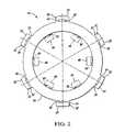
- FIG. 2is a plan view of the coulomb damper insert shown in FIGS. 1 a - d , with alternative configurations shown in phantom.
- FIGS. 1 a and 1 ba mold 10 in accordance with the invention having upper and lower mold halves 12 , 14 that form a cavity 16 therebetween for casting a friction damped disc brake rotor in accordance with the invention.
- FIG. 1 bshows a portion of a coulomb damper insert 18 , highlighted in FIG. 1 a , which is pre-positioned within the mold 10 and having tabs 20 which rest on cutout portions 22 , 24 of the lower mold half 14 .
- FIG. 1 cwhen the upper and lower mold halves 12 , 14 are closed together, the tabs 20 are supported between the cutout portions 22 , 24 of the lower mold half 14 and the lands 26 , 28 , respectively of the upper mold half 12 .
- the coulomb damper insert 18is shown in plan view. As shown, the coulomb damper insert 18 has a generally annular body 30 with tabs 20 extending therefrom. Each tab includes a distal portion 32 and a proximal portion 34 . During casting, the distal portion 32 is secured between the cutout portions 22 , 24 and the lands 26 , 28 , respectively, shown in FIG. 1 c , while the proximal portion 34 of each tab 20 is exposed to molten casting material 39 within the mold cavity 16 . The proximal portion 34 of each tab 20 at least partially defines an orifice 35 that is generally elliptical in shape. Those skilled in the art will recognize that the orifice 35 may be any shape, such as circular, diamond, rectangular, triangular, etc, while remaining within the scope of that which is claimed.
- the mold 10is preferably formed from sand, and the coulomb damper insert 18 is preferably a pre-manufactured steel component having a coating on opposing surfaces 36 , 38 (shown in FIG. 1 b ) of the generally annular body 30 . These coated surfaces 36 , 38 do not bond with the casting material 39 during the casting operation, shown in FIG. 1 c . The lack of “wetting” or affinity along these coated surfaces 36 , 38 produces the unbonded interfacial boundary between the generally annular body 30 and a rotor cheek 44 desired for damping effectiveness.
- the tabs 20may be configured in a manner to bond with the casting material 39 forming the rotor cheek 44 or a coulomb damped disc brake rotor 40 , shown in FIG. 1 d.
- the coated surfaces 36 , 38 of the coulomb damper insert 18do not bond with the casting material 39 of the rotor cheek 44 , a proper interfacial boundary is formed with the rotor cheek 44 for damping.
- the bonding of the tabs 20 , particularly the proximal portions 34 thereof, with the casting material 39 of the rotor cheek 44prevents corrosion causing exterior elements, such as water and salt, from reaching the interfacial boundary between the coulomb damper insert 18 and the rotor cheek 44 .
- This bondingmay be achieved by first coating the tabs 20 with the same material which forms the coated surfaces 36 , 38 of the body 30 and then cleaning the coating off the tabs 20 at the proximal portions 34 to locally remove the coating to allow the tabs 20 to be micro-welded or otherwise bonded to the casting material 39 thereby effectively sealing the rest of the coulomb damper insert 18 to rotor cheek 44 interface from intrusion by water or other elements.
- a graphite coating or similar fluxing agentmay be applied to the tabs 20 to enhance bonding with the casting material 39 . So-called “wetting” of the tabs 20 can also be accomplished by masking the tab 20 prior to application of the coating.
- the coulomb damper insert 18may be formed from any material having a melting point higher than that of casting material 39 , such that the coulomb damper insert 18 would not be melted during the casting process.
- the casting material 39is iron and, as mentioned hereinabove, the coulomb damper insert 18 is formed from steel.
- the above-referenced coated surfaces 36 , 38must first be cleaned free of oil, rust or dirt.
- Degreasersmay be used to remove thin films of oil, and steel wool may be used to remove rust.
- the best resultsare attained when the coulomb damper insert 18 is sand blasted, which removes both oil and rust. It also roughens the surface, which promotes adherence of the coating.
- the preferred coating materialis a ceramic mold wash sold under the trade name IRONKOTE, and is available from Vesuvius Canada Refractories, Inc. of Welland, Ontario. IRONKOTE has alumina and silica particles mixed with an organic binder.
- the coatingpreferably has a thickness between approximately 50 and 300 micrometers. It should be noted that other ceramic coatings that prevent wetting of the coulomb damper insert 18 and having a melting point higher than that of the casting material 39 may be used. Additionally, non- ceramic coatings such as those with hydrocarbon based carriers may be used while remaining within the scope of that which is claimed.
- the insertis cleaned and free of oil and other contaminates, it is dipped in or sprayed with IRONKOTE on both surfaces 36 , 38 and allowed to air dry.
- the coulomb damper insert 18is then placed in an oven at 500 degrees F. for 45 minutes. This reduces the amount of absorbed water and organic binders within the ceramic coating, and provides a relatively uniform coating; however, it should be noted that alternate coatings may require alternate drying procedures.
- steel woolmay be used to locally remove the coating from the tabs 20 . With the coating removed from the tabs 20 , bonding may occur between the casting material 39 and the tabs 20 of the coulomb damper insert 18 .
- the mold 10is shown in the open position with the friction damped disc brake rotor 40 removed from the mold cavity 16 , as shown in FIG. 1 a .
- the coulomb damped disc brake rotor 40has a hat portion 42 with the rotor cheek 44 extending about the periphery thereof, and the coulomb damper insert 18 positioned within the rotor cheek 44 .
- the distal end 32 of each of the tabs 20 of the coulomb damper insert 18is removed, such as by machining, after the coulomb damped disc brake rotor 40 is removed from the mold 10 .
- the orifice 35allows the tab 20 to maintain the support necessary to locate the coulomb damper insert 18 within the mold.
- the presence of the orifice 35reduces the external exposure of the coulomb damper insert 18 from within the rotor cheek 44 , thus the likelihood of internal intrusion of external elements, such as water and salt, within the rotor cheek 44 is greatly reduced.
- the locating tabsmay be formed on the inside diameter (i.e. radially inwardly extending), outside diameter (i.e. radially outwardly extending), or both to locate and stabilize the coulomb damper insert 18 during the casting operation.
- the coulomb damper insert 18 of FIG. 2has optional radially inwardly extending internal tabs 48 , shown in phantom, at least partially defining corresponding orifices 50 , also shown in phantom.
- the number and placement of tabs 48 and 20will depend, in part, on the specific rotor cheek 44 geometry and dimensions, and on the thickness of the coulomb damper insert 18 .
- the coulomb damper insert 18is preferably 1.5 to 2 mm in thickness, but other thicknesses are envisioned.
- the thickness of the coulomb damper insert 18is chosen to prevent bending or flexing of the coulomb damper insert 18 while not being so thick as to “chill” the surrounding molten casting material 39 during casting to the point that an objectionable amount of carbide is produced.
- the gap at the interface between the tabs 20 , 48 and the rotor cheek 44is substantially eliminated in order to isolate the interfaces between the coulomb damper insert 18 and the rotor cheek 44 from the exterior environment thereby eliminating corrosion issues in service of the coulomb damped disc brake rotor 40 .
- the location of the orifices 35 and 50 within the coulomb damper insert 18are preferably chosen such that the area of the coulomb damper insert 18 exposed after the machining of the rotor cheek 44 is minimized.
- the major axis of the orifices 35 and 50is located generally coextensively with the radial periphery of a rotor cheek 44 after finish machining of the rotor cheek 44 . Additionally, more than one coulomb damper insert 18 may be cast within the rotor cheek 44 .
- the orifices 35 , 50facilitate mold filling while reducing the tendency of the casting material 39 to move or dislodge the coulomb damper insert 18 during the casting operation.
- the orifices 35 , 50help to prevent molten casting material 39 from lifting or shifting the coulomb damper insert 18 , as the mold 10 is filled from below through the gate 47 , shown in FIG. 1 c .
- the molten casting material 39is not directed or splashed onto the coulomb damper insert 18 prematurely.
- quiescent mold fillingprevents splashing and premature solidification of droplets of molten casting material 39 on the coulomb damper insert 18 prior to general contact with molten casting material 39 during filling of the mold 10 .
- the molten casting material 39is preferably filtered at the gate 47 with a ceramic filter, not shown, to reduce slag related defects.
- the present inventionfurther provides a method of casting a coulomb damped disc brake rotor 40 including the steps of: A) providing the mold 10 having the general shape of the coulomb damped disc brake rotor 40 ; B) placing the coulomb damper insert 18 having a generally annular body 30 and at least one tab 20 extending generally radially from the generally annular body 30 , wherein the at least one tab 20 operates to locate the coulomb damper insert 18 within the mold 10 , and wherein the at least one tab 20 at least partially defines an orifice 35 ; and C) causing casting material 39 to enter the mold 10 to substantially encapsulate the coulomb damper insert 18 with the casting material 39 to form a rotor cheek 44 of the coulomb damped disc brake rotor 40 .
- the present inventionmay reduce disc brake squeal and may limit the potential for corrosion of the coulomb damper insert 18 after machining. It should be understood that the procedure outlined above can also be used with vented rotor cheek configurations, with a note that an insert or inserts are provided at both or selective one of the rotor cheeks. To those skilled in the art to which this invention pertains, the above described preferred embodiment may be subject to change or modification. Such change or modification can be carried out without departing from the scope of the invention, which is intended to be limited only by the scope of the appended claims.
Landscapes
- Engineering & Computer Science (AREA)
- General Engineering & Computer Science (AREA)
- Mechanical Engineering (AREA)
- Braking Arrangements (AREA)
Abstract
Description
Claims (31)
Priority Applications (3)
| Application Number | Priority Date | Filing Date | Title |
|---|---|---|---|
| US11/554,234US8245758B2 (en) | 2006-10-30 | 2006-10-30 | Coulomb damped disc brake rotor and method of manufacturing |
| US12/025,967US8163399B2 (en) | 2004-10-08 | 2008-02-05 | Damped products and methods of making and using the same |
| US12/174,163US20090020383A1 (en) | 2006-06-27 | 2008-07-16 | Damped part |
Applications Claiming Priority (1)
| Application Number | Priority Date | Filing Date | Title |
|---|---|---|---|
| US11/554,234US8245758B2 (en) | 2006-10-30 | 2006-10-30 | Coulomb damped disc brake rotor and method of manufacturing |
Related Parent Applications (1)
| Application Number | Title | Priority Date | Filing Date |
|---|---|---|---|
| US11/475,756Continuation-In-PartUS7937819B2 (en) | 2004-10-08 | 2006-06-27 | Method of manufacturing a friction damped disc brake rotor |
Related Child Applications (3)
| Application Number | Title | Priority Date | Filing Date |
|---|---|---|---|
| US11/440,916Continuation-In-PartUS7775332B2 (en) | 2004-10-08 | 2006-05-25 | Bi-metal disc brake rotor and method of manufacturing |
| US78082807AContinuation-In-Part | 2004-10-08 | 2007-07-20 | |
| US12/174,163Continuation-In-PartUS20090020383A1 (en) | 2006-06-27 | 2008-07-16 | Damped part |
Publications (2)
| Publication Number | Publication Date |
|---|---|
| US20080099289A1 US20080099289A1 (en) | 2008-05-01 |
| US8245758B2true US8245758B2 (en) | 2012-08-21 |
Family
ID=39328797
Family Applications (1)
| Application Number | Title | Priority Date | Filing Date |
|---|---|---|---|
| US11/554,234Expired - Fee RelatedUS8245758B2 (en) | 2004-10-08 | 2006-10-30 | Coulomb damped disc brake rotor and method of manufacturing |
Country Status (1)
| Country | Link |
|---|---|
| US (1) | US8245758B2 (en) |
Cited By (10)
| Publication number | Priority date | Publication date | Assignee | Title |
|---|---|---|---|---|
| US20110198169A1 (en)* | 2005-09-19 | 2011-08-18 | GM Global Technology Operations LLC | Bi-metal disc brake rotor and method of manufacturing |
| US20110220313A1 (en)* | 2007-07-20 | 2011-09-15 | GM Global Technology Operations LLC | Method of casting damped part with insert |
| US20140150985A1 (en)* | 2010-10-12 | 2014-06-05 | GM Global Technology Operations LLC | Bimetallic casting |
| US20140158457A1 (en)* | 2012-12-12 | 2014-06-12 | GM Global Technology Operations LLC | Coulomb frictional damping coated product |
| US8857577B2 (en) | 2011-12-21 | 2014-10-14 | Brembo North America, Inc. | Damped brake rotor |
| US9188180B2 (en) | 2013-05-13 | 2015-11-17 | GM Global Technology Operations LLC | Brake rotor and method of manufacturing the same |
| US9841072B2 (en) | 2014-10-02 | 2017-12-12 | Ford Global Technologies, Llc | Damped brake components and methods of manufacturing the same |
| US10060495B2 (en) | 2016-09-15 | 2018-08-28 | Ford Global Technologies, Llc | Dry friction damped mechanical and structural metal components and methods of manufacturing the same |
| DE102018108350A1 (en) | 2017-04-12 | 2018-10-18 | Ford Global Technologies, Llc | COULOMBASE FRICTION MEASURED COMPONENTS AND METHOD FOR MANUFACTURING THE SAME |
| US10197120B2 (en) | 2014-10-02 | 2019-02-05 | Ford Global Technologies, Llc | Damped brake components and methods of manufacturing the same |
Families Citing this family (32)
| Publication number | Priority date | Publication date | Assignee | Title |
|---|---|---|---|---|
| US8163399B2 (en)* | 2004-10-08 | 2012-04-24 | GM Global Technology Operations LLC | Damped products and methods of making and using the same |
| US7975750B2 (en) | 2004-10-08 | 2011-07-12 | GM Global Technology Operations LLC | Coulomb friction damped disc brake rotors |
| US8245758B2 (en) | 2006-10-30 | 2012-08-21 | GM Global Technology Operations LLC | Coulomb damped disc brake rotor and method of manufacturing |
| US9174274B2 (en) | 2006-05-25 | 2015-11-03 | GM Global Technology Operations LLC | Low mass multi-piece sound dampened article |
| US8056233B2 (en) | 2006-06-27 | 2011-11-15 | GM Global Technology Operations LLC | Method of manufacturing an automotive component member |
| JP4537423B2 (en)* | 2007-06-11 | 2010-09-01 | 株式会社日立製作所 | Storage device information control method of user operation terminal |
| US9527132B2 (en)* | 2007-07-20 | 2016-12-27 | GM Global Technology Operations LLC | Damped part with insert |
| US8758902B2 (en)* | 2007-07-20 | 2014-06-24 | GM Global Technology Operations LLC | Damped product with an insert having a layer including graphite thereon and methods of making and using the same |
| US9534651B2 (en)* | 2007-07-20 | 2017-01-03 | GM Global Technology Operations LLC | Method of manufacturing a damped part |
| US20100122880A1 (en)* | 2008-11-17 | 2010-05-20 | Gm Global Technology Operations, Inc. | Surface configurations for damping inserts |
| US7823763B2 (en)* | 2007-08-01 | 2010-11-02 | Gm Global Technology Operations, Inc. | Friction welding method and products made using the same |
| US20090032211A1 (en)* | 2007-08-03 | 2009-02-05 | Gm Global Technology Operations, Inc. | Method for securing an insert in the manufacture of a damped part |
| US20090035598A1 (en)* | 2007-08-03 | 2009-02-05 | Gm Global Technology Operations, Inc. | Product with metallic foam and method of manufacturing the same |
| US8118079B2 (en)* | 2007-08-17 | 2012-02-21 | GM Global Technology Operations LLC | Casting noise-damped, vented brake rotors with embedded inserts |
| US8020300B2 (en)* | 2007-08-31 | 2011-09-20 | GM Global Technology Operations LLC | Cast-in-place torsion joint |
| US8210232B2 (en)* | 2007-09-20 | 2012-07-03 | GM Global Technology Operations LLC | Lightweight brake rotor and components with composite materials |
| US7836938B2 (en)* | 2007-09-24 | 2010-11-23 | Gm Global Technology Operations, Inc. | Insert with tabs and damped products and methods of making the same |
| US8028739B2 (en) | 2007-10-29 | 2011-10-04 | GM Global Technology Operations LLC | Inserts with holes for damped products and methods of making and using the same |
| US8091609B2 (en)* | 2008-01-04 | 2012-01-10 | GM Global Technology Operations LLC | Method of forming casting with frictional damping insert |
| US20110005873A1 (en)* | 2008-04-08 | 2011-01-13 | Volvo Construction Equipment Ab | Brake for a work machine, a wheel hub unit and a work machine |
| US8104162B2 (en)* | 2008-04-18 | 2012-01-31 | GM Global Technology Operations LLC | Insert with filler to dampen vibrating components |
| US20090260931A1 (en)* | 2008-04-18 | 2009-10-22 | Gm Global Technology Operations, Inc. | Filler material to dampen vibrating components |
| US9163682B2 (en)* | 2008-07-24 | 2015-10-20 | GM Global Technology Operations LLC | Friction damped brake drum |
| US9500242B2 (en)* | 2008-12-05 | 2016-11-22 | GM Global Technology Operations LLC | Component with inlay for damping vibrations |
| US20100282550A1 (en)* | 2009-05-07 | 2010-11-11 | Gm Global Technology Operations, Inc. | Mode altering insert for vibration reduction in components |
| US20100294063A1 (en)* | 2009-05-22 | 2010-11-25 | Gm Global Technology Operations, Inc. | Friction damped gears |
| US8714232B2 (en) | 2010-09-20 | 2014-05-06 | GM Global Technology Operations LLC | Method of making a brake component |
| US8904642B2 (en) | 2011-08-08 | 2014-12-09 | GM Global Technology Operations LLC | Manufacturing a vibration damped light metal alloy part |
| US9027718B2 (en) | 2011-08-31 | 2015-05-12 | GM Global Technology Operations LLC | Light-weight and sound-damped brake rotor and method of manufacturing the same |
| US8968855B2 (en) | 2011-10-25 | 2015-03-03 | GM Global Technology Operations LLC | Method of forming a component having an insert |
| US9016445B2 (en) | 2011-11-09 | 2015-04-28 | GM Global Technology Operations LLC | Light-weight and sound-damped brake rotor and method of manufacturing the same |
| DE102014213402A1 (en)* | 2014-07-10 | 2016-01-14 | Robert Bosch Gmbh | Brake disk for a motor vehicle, braking device |
Citations (132)
| Publication number | Priority date | Publication date | Assignee | Title |
|---|---|---|---|---|
| US974024A (en) | 1910-08-24 | 1910-10-25 | Charles B Carter | Metal-founding. |
| US1484421A (en) | 1924-02-19 | James s | ||
| US1989211A (en) | 1930-11-21 | 1935-01-29 | Bendix Brake Co | Composite brake drum |
| US2012838A (en) | 1933-10-17 | 1935-08-27 | Sydney G Tilden | Noise-dampener for brake drums |
| US2026878A (en) | 1932-06-14 | 1936-01-07 | Budd Wheel Co | Method of making brake drums |
| US2288438A (en) | 1940-08-08 | 1942-06-30 | Dach Max | Brake drum |
| US2603316A (en) | 1952-07-15 | Brake rotor | ||
| US2978793A (en) | 1958-04-16 | 1961-04-11 | Edward R Lamson | Method of lubricating anti-friction bearings |
| US3085391A (en) | 1960-10-13 | 1963-04-16 | S & M Products Company Inc | Automatic hydraulic transmission |
| US3127959A (en) | 1962-03-12 | 1964-04-07 | Wengrowski Bronislaus | Cooling device for brake drums and shoes |
| US3147828A (en) | 1961-08-17 | 1964-09-08 | Dayton Malleable Iron Co | Brake drum construction |
| US3292746A (en) | 1965-11-05 | 1966-12-20 | Kelsey Hayes Co | Vibration dampener for disk brakes |
| CH428319A (en) | 1965-09-08 | 1967-01-15 | Cav Ltd | Multi-cylinder internal combustion engine crankcases and process for their manufacture |
| US3378115A (en) | 1965-07-14 | 1968-04-16 | Gen Motors Corp | Disc damper |
| US3425523A (en) | 1967-06-12 | 1969-02-04 | Kelsey Hayes Co | Ventilated rotor with vibration dampener |
| US3509973A (en) | 1967-04-28 | 1970-05-05 | Isuzu Motors Ltd | Anti-squeal disc braking device |
| US3575270A (en) | 1967-12-09 | 1971-04-20 | Jurid Werke Gmbh | Friction means |
| GB1230274A (en) | 1968-12-21 | 1971-04-28 | ||
| US3774472A (en) | 1972-10-02 | 1973-11-27 | Ammco Tools Inc | Vibration dampener |
| US3841448A (en) | 1973-06-14 | 1974-10-15 | Budd Co | Reinforced brake drum |
| DE2446938A1 (en) | 1974-09-28 | 1976-04-15 | Jurid Werke Gmbh | Noise damping device for device for disc brake - has cast in ring of granular material between friction faces |
| US3975894A (en) | 1972-12-28 | 1976-08-24 | Toyoda Automatic Loom Works, Ltd. | Vibration and sound dampening means |
| DE2537038A1 (en) | 1975-08-20 | 1977-03-03 | Engels Gmbh August | Noise damper for disc or drum brake - is solid or segmented graphite insert ring cast into disc |
| US4049085A (en) | 1976-08-10 | 1977-09-20 | Safety Racing Equipment, Incorporated | Caliper brake with assembly for rotor attachment to hub |
| US4072219A (en) | 1974-12-07 | 1978-02-07 | Itt Industries, Incorporated | Multi-part disc brake |
| US4195713A (en) | 1974-05-29 | 1980-04-01 | Reduc Acoustics Ab | Sandwich structures with partial damping layers |
| US4250950A (en) | 1978-11-03 | 1981-02-17 | Swiss Aluminium Ltd. | Mould with roughened surface for casting metals |
| US4278153A (en) | 1978-11-24 | 1981-07-14 | Goodyear Aerospace Corporation | Brake friction material with reinforcement material |
| US4338758A (en) | 1978-04-18 | 1982-07-13 | Reduc Acoustics Ab | Vibration damped structures and objects |
| JPS57154533A (en) | 1981-03-17 | 1982-09-24 | Nissan Motor Co Ltd | Rotor of disc brake |
| US4379501A (en) | 1980-02-27 | 1983-04-12 | Nissan Motor Co., Ltd. | Ventilated disk brake |
| US4475634A (en) | 1983-02-25 | 1984-10-09 | General Motors Corporation | Disc brake rotor damping |
| US4523666A (en) | 1983-08-03 | 1985-06-18 | Motor Wheel Corporation | Brake rotor with vibration harmonic suppression, and method of manufacture |
| US4529079A (en) | 1980-01-16 | 1985-07-16 | Borg-Warner Corporation | Cushion-bonded driven disc assembly and method of construction |
| EP0205713A1 (en) | 1985-06-10 | 1986-12-30 | Motor Wheel Corporation | Brake rotor with vibration harmonic suppression |
| US4905299A (en) | 1989-08-14 | 1990-02-27 | Chrysler Motors Corporation | Hold down bearing retainer |
| US5004078A (en)* | 1988-11-09 | 1991-04-02 | Aisin Takaoka Co., Ltd. | Ventilated disk and process for making same |
| US5025547A (en) | 1990-05-07 | 1991-06-25 | Aluminum Company Of America | Method of providing textures on material by rolling |
| US5083643A (en) | 1989-10-10 | 1992-01-28 | Abex Corporation | Noise abating brake shoe |
| US5115891A (en) | 1990-12-17 | 1992-05-26 | The Budd Company | Composite brake drum with improved locating means for reinforcement assembly |
| US5139117A (en) | 1990-08-27 | 1992-08-18 | General Motors Corporation | Damped disc brake rotor |
| US5143184A (en) | 1991-02-14 | 1992-09-01 | Allied-Signal Inc. | Carbon composite brake disc with positive vibration damping |
| US5183632A (en) | 1991-03-20 | 1993-02-02 | Akebono Brake Industry Co., Ltd. | Method of manufacturing an aluminum-base composite disc rotor |
| US5184662A (en) | 1990-01-22 | 1993-02-09 | Quick Nathaniel R | Method for clad-coating ceramic particles |
| US5259486A (en) | 1992-02-12 | 1993-11-09 | The Budd Company | Integral casted labrynth ring for brake drum |
| US5310025A (en) | 1992-07-23 | 1994-05-10 | Allied-Signal Inc. | Aircraft brake vibration damper |
| US5417313A (en) | 1991-07-23 | 1995-05-23 | Akebno Brake Industry Co., Ltd. | Disc rotor for preventing squeal |
| US5416962A (en) | 1993-12-08 | 1995-05-23 | Eagle-Picher Industries, Inc. | Method of manufacture of vibration damper |
| US5509510A (en) | 1993-06-30 | 1996-04-23 | Kelsey-Hayes Company | Composite disc brake rotor and method for producing same |
| US5530213A (en) | 1993-05-17 | 1996-06-25 | Ford Motor Company | Sound-deadened motor vehicle exhaust manifold |
| US5582231A (en) | 1995-04-28 | 1996-12-10 | General Motors Corporation | Sand mold member and method |
| US5620042A (en)* | 1993-06-30 | 1997-04-15 | Kelsey-Hayes Company | Method of casting a composite disc brake rotor |
| US5660251A (en) | 1995-05-26 | 1997-08-26 | Sumitomo Electric Industries, Ltd. | Vibration damping device for disc brake |
| WO1998023877A1 (en) | 1996-11-27 | 1998-06-04 | Alliedsignal Inc. | Multi-disk brake actuator for vibration damping |
| DE19649919A1 (en) | 1996-12-02 | 1998-06-04 | Actech Gmbh Adv Casting Tech | Brake members made of composite casting, namely brake drum, brake disc or the like, and composite casting method for the production of brake members |
| US5789066A (en) | 1994-09-16 | 1998-08-04 | Sidmar N.V. | Method and device for manufacturing cold rolled metal sheets or strips and metal sheets or strips obtained |
| US5819882A (en) | 1996-04-02 | 1998-10-13 | Alliedsignal Inc. | Multi-disc brake actuator for vibration damping |
| US5855257A (en) | 1996-12-09 | 1999-01-05 | Chrysler Corporation | Damper for brake noise reduction |
| US5862892A (en) | 1996-04-16 | 1999-01-26 | Hayes Lemmerz International Inc. | Composite rotor for caliper disc brakes |
| US5878843A (en) | 1997-09-24 | 1999-03-09 | Hayes Lemmerz International, Inc. | Laminated brake rotor |
| US5927447A (en) | 1997-06-27 | 1999-07-27 | Hayes Lemmerz International, Inc. | Composite brake drum |
| US5965249A (en) | 1997-08-07 | 1999-10-12 | Gore Enterprise Holdings, Inc. | Vibration damping composite material |
| JPH11342461A (en) | 1998-05-29 | 1999-12-14 | Isuzu Motors Ltd | Casting method for casting with insert member |
| US6047794A (en) | 1996-12-19 | 2000-04-11 | Sumitomo Electric Industries, Ltd. | Vibration damper for use in wheel brake |
| US6073735A (en) | 1998-02-02 | 2000-06-13 | Aluminium Rheinfelden Gmbh | Brake disc |
| US6112865A (en) | 1996-12-09 | 2000-09-05 | Chrysler Corporation | Damper for brake noise reduction (brake drums) |
| GB2328952B (en) | 1997-09-09 | 2001-01-10 | T & N Technology Ltd | Disc brake rotor |
| DE19948009C1 (en) | 1999-10-06 | 2001-03-01 | Continental Teves Ag & Co Ohg | Brake disc for automobile disc brakes has 2 friction ring discs attached to disc head with ventilation channels between radial struts of friction disc rings provided with radial rupture points |
| US6206150B1 (en) | 1998-12-29 | 2001-03-27 | Hayes Lemmerz International Inc. | Composite brake drum having a balancing skirt |
| US6216827B1 (en) | 1996-07-24 | 2001-04-17 | Toyota Jidosha Kabushiki Kaisha | Disc brake rotor which generates vibration having a large component in a direction of a rotational axis of the disc brake rotor |
| US6223866B1 (en) | 2000-06-30 | 2001-05-01 | Kelsey-Hayes Company | Damped pad spring for use in a disc brake assembly |
| US6231456B1 (en) | 1999-04-05 | 2001-05-15 | Graham Rennie | Golf shaft vibration damper |
| WO2001036836A1 (en) | 1999-11-15 | 2001-05-25 | Newtech Brake Corporation Inc. | Rotor disk assembly for full contact brake |
| US6241055B1 (en) | 1998-09-11 | 2001-06-05 | Hayes Lemmerz International, Inc. | Rotor with viscoelastic vibration reducing element and method of making the same |
| US6241056B1 (en) | 1998-12-29 | 2001-06-05 | Hayes Lemmerz International, Inc. | Composite brake drum |
| KR20010049837A (en) | 1999-09-02 | 2001-06-15 | 토마스 더블유. 버크맨 | Air damper with graphite coated lip seal |
| US6283258B1 (en) | 2000-08-29 | 2001-09-04 | Ford Global Technologies, Inc. | Brake assembly with noise damping |
| US6302246B1 (en) | 1998-12-23 | 2001-10-16 | Daimlerchrysler Ag | Brake unit |
| US6357557B1 (en) | 2000-12-20 | 2002-03-19 | Kelsey-Hayes Company | Vehicle wheel hub and brake rotor and method for producing same |
| DE60000008T2 (en) | 2000-03-09 | 2002-03-28 | Freni Brembo S.P.A., Curno | Vented disc for disc brake |
| US6405839B1 (en) | 2001-01-03 | 2002-06-18 | Delphi Technologies, Inc. | Disc brake rotor |
| US20020104721A1 (en) | 2000-09-14 | 2002-08-08 | Marion Schaus | Disc brakes |
| US6465110B1 (en) | 2000-10-10 | 2002-10-15 | Material Sciences Corporation | Metal felt laminate structures |
| US6481545B1 (en) | 2001-03-30 | 2002-11-19 | Nichias Corporation | Vibration damping shim structure |
| US6507716B2 (en) | 2000-05-30 | 2003-01-14 | Sharp Kabushiki Kaisha | Image forming apparatus having user and stored job indentification and association capability, a stored job content display and multiple job type image forming control displays |
| US6505716B1 (en) | 1999-11-05 | 2003-01-14 | Hayes Lemmerz International, Inc. | Damped disc brake rotor |
| US20030037999A1 (en) | 2001-08-23 | 2003-02-27 | Toshio Tanaka | Vibration inhibiting structure for rotor |
| DE10141698A1 (en) | 2001-08-25 | 2003-03-06 | Bosch Gmbh Robert | Vibration-damped component of a motor vehicle |
| US6543518B1 (en) | 1999-10-25 | 2003-04-08 | Tooling & Equipment International | Apparatus and method for casting |
| US20030127297A1 (en) | 2002-01-09 | 2003-07-10 | Smith Anthony L. | Magnetorheological fluid fan drive design for manufacturability |
| JP2003214465A (en) | 2002-01-22 | 2003-07-30 | Koyo Seiko Co Ltd | Disc rotor for brake and bearing device |
| US20030141154A1 (en) | 2000-05-08 | 2003-07-31 | Yvon Rancourt | Rotor for disk brake assembly |
| US6648055B1 (en) | 1999-04-16 | 2003-11-18 | Daimlerchrysler Ag | Casting tool and method of producing a component |
| US20030213658A1 (en) | 2002-05-16 | 2003-11-20 | Advics Co., Ltd. | Disc brake |
| JP2004011841A (en) | 2002-06-10 | 2004-01-15 | Kawasaki Heavy Ind Ltd | brake disc |
| US20040031581A1 (en) | 2002-03-18 | 2004-02-19 | Herreid Richard M. | Method and apparatus for making a sand core with an improved production rate |
| US20040045692A1 (en) | 2002-09-10 | 2004-03-11 | Redemske John A | Method of heating casting mold |
| US20040074712A1 (en) | 2002-10-22 | 2004-04-22 | Ford Global Technologies, Inc. | Brake assembly with tuned mass damper |
| US20040084260A1 (en) | 2002-11-01 | 2004-05-06 | J. L. French Automotive Castings, Inc. | Integrated brake rotor |
| US6799664B1 (en) | 2002-03-29 | 2004-10-05 | Kelsey-Hayes Company | Drum brake assembly |
| US20040242363A1 (en) | 2003-05-30 | 2004-12-02 | Toyota Jidosha Kabushiki Kaisha | Rotating shaft support apparatus and differential gear unit |
| US20050011628A1 (en)* | 2003-07-18 | 2005-01-20 | John Frait | Method and apparatus for forming a part with dampener |
| US6880681B2 (en) | 2000-05-29 | 2005-04-19 | Honda Giken Kogyo Kabushiki Kaisha | Brake drum and method for producing the same |
| US6890218B2 (en) | 2001-11-05 | 2005-05-10 | Ballard Power Systems Corporation | Three-phase connector for electric vehicle drivetrain |
| US6899158B2 (en) | 2002-09-04 | 2005-05-31 | Kioritz Corporation | Insert core and method for manufacturing a cylinder for internal combustion engine by making use of the insert core |
| US20050150222A1 (en) | 2003-12-30 | 2005-07-14 | Kalish Martin W. | One piece catalytic converter with integral exhaust manifold |
| US6932917B2 (en) | 2001-08-06 | 2005-08-23 | General Motors Corporation | Magnetorheological fluids |
| US20050183909A1 (en) | 2004-01-21 | 2005-08-25 | Rau Charles B.Iii | Disc brake rotor assembly and method for producing same |
| US20050193976A1 (en) | 2004-03-04 | 2005-09-08 | Kozo Suzuki | Swirl forming device in combustion engine |
| CN1757948A (en) | 2004-10-08 | 2006-04-12 | 通用汽车公司 | Coulomb friction damped disc brake rotors |
| US7066235B2 (en) | 2002-05-07 | 2006-06-27 | Nanometal, Llc | Method for manufacturing clad components |
| US7112749B2 (en) | 2004-06-23 | 2006-09-26 | Sensata Technologies, Inc. | Sensor mounting apparatus for minimizing parasitic stress |
| US20060243547A1 (en) | 2005-04-04 | 2006-11-02 | Holger Keller | Brake disc, particularly an internally ventilated brake disc |
| DE60116780T2 (en) | 2001-07-27 | 2006-11-02 | Freni Brembo S.P.A. | METHOD FOR PRODUCING A BRAKE PULLEY OF A BRAKE DISC WITH VENTILATION CHANNELS AND MANUFACTURED BRAKE RING |
| CN2863313Y (en) | 2006-01-25 | 2007-01-31 | 秦经世 | Positioning device for cooling ring for piston |
| US7178795B2 (en) | 2003-12-23 | 2007-02-20 | Basf Corporation | Mounting assembly for a vehicle suspension component |
| US20070039710A1 (en) | 2005-08-19 | 2007-02-22 | Newcomb Thomas P | Foundry mold assembly device and method |
| US20070056815A1 (en) | 2005-09-15 | 2007-03-15 | Hanna Michael D | Bi-metal disc brake rotor and method of manufacturing |
| US20070062664A1 (en) | 2005-09-20 | 2007-03-22 | Schroth James G | Method of casting components with inserts for noise reduction |
| US20070062768A1 (en)* | 2005-09-19 | 2007-03-22 | Hanna Michael D | Bi-metal disc brake rotor and method of manufacturing |
| US20070142149A1 (en) | 2005-11-23 | 2007-06-21 | Kleber Richard M | Pulley assembly and method |
| US20070166425A1 (en) | 2006-01-17 | 2007-07-19 | Utsugi Masanori | Optical Element Molding Device |
| US20070235270A1 (en) | 2006-04-11 | 2007-10-11 | Thyssenkrupp-Waupaca Division | Insert for manufacture of an enhanced sound dampening composite rotor casting and method thereof |
| US7293755B2 (en) | 2004-11-04 | 2007-11-13 | Honda Motor Co., Ltd. | Vibration isolation device |
| US20070298275A1 (en) | 2006-06-27 | 2007-12-27 | Gm Global Technology Operations, Inc. | Damped automotive components with cast in place inserts and method of making same |
| US20080099289A1 (en) | 2006-10-30 | 2008-05-01 | Gm Global Technology Operations, Inc. | Coulomb damped disc brake rotor and method of manufacturing |
| US20080185249A1 (en) | 2004-10-08 | 2008-08-07 | Gm Global Technology Operations, Inc. | Damped products and methods of making and using the same |
| US20090032569A1 (en) | 2007-08-01 | 2009-02-05 | Gm Global Technology Operations, Inc. | Friction welding method and products made using the same |
| US20090107787A1 (en)* | 2007-10-29 | 2009-04-30 | Gm Global Technology Operations, Inc. | Inserts with holes for damped products and methods of making and using the same |
| US7594568B2 (en) | 2005-11-30 | 2009-09-29 | Gm Global Technology Operations, Inc. | Rotor assembly and method |
| US7604098B2 (en) | 2005-08-01 | 2009-10-20 | Gm Global Technology Operations, Inc. | Coulomb friction damped disc brake caliper bracket |
| US7836938B2 (en) | 2007-09-24 | 2010-11-23 | Gm Global Technology Operations, Inc. | Insert with tabs and damped products and methods of making the same |
Family Cites Families (1)
| Publication number | Priority date | Publication date | Assignee | Title |
|---|---|---|---|---|
| PL366911A1 (en)* | 2001-05-21 | 2005-02-07 | Nektar Therapeutics | Pulmonary administration of chemically modified insulin |
- 2006
- 2006-10-30USUS11/554,234patent/US8245758B2/ennot_activeExpired - Fee Related
Patent Citations (140)
| Publication number | Priority date | Publication date | Assignee | Title |
|---|---|---|---|---|
| US1484421A (en) | 1924-02-19 | James s | ||
| US2603316A (en) | 1952-07-15 | Brake rotor | ||
| US974024A (en) | 1910-08-24 | 1910-10-25 | Charles B Carter | Metal-founding. |
| US1989211A (en) | 1930-11-21 | 1935-01-29 | Bendix Brake Co | Composite brake drum |
| US2026878A (en) | 1932-06-14 | 1936-01-07 | Budd Wheel Co | Method of making brake drums |
| US2012838A (en) | 1933-10-17 | 1935-08-27 | Sydney G Tilden | Noise-dampener for brake drums |
| US2288438A (en) | 1940-08-08 | 1942-06-30 | Dach Max | Brake drum |
| US2978793A (en) | 1958-04-16 | 1961-04-11 | Edward R Lamson | Method of lubricating anti-friction bearings |
| US3085391A (en) | 1960-10-13 | 1963-04-16 | S & M Products Company Inc | Automatic hydraulic transmission |
| US3147828A (en) | 1961-08-17 | 1964-09-08 | Dayton Malleable Iron Co | Brake drum construction |
| US3127959A (en) | 1962-03-12 | 1964-04-07 | Wengrowski Bronislaus | Cooling device for brake drums and shoes |
| US3378115A (en) | 1965-07-14 | 1968-04-16 | Gen Motors Corp | Disc damper |
| CH428319A (en) | 1965-09-08 | 1967-01-15 | Cav Ltd | Multi-cylinder internal combustion engine crankcases and process for their manufacture |
| US3292746A (en) | 1965-11-05 | 1966-12-20 | Kelsey Hayes Co | Vibration dampener for disk brakes |
| US3509973A (en) | 1967-04-28 | 1970-05-05 | Isuzu Motors Ltd | Anti-squeal disc braking device |
| US3425523A (en) | 1967-06-12 | 1969-02-04 | Kelsey Hayes Co | Ventilated rotor with vibration dampener |
| US3575270A (en) | 1967-12-09 | 1971-04-20 | Jurid Werke Gmbh | Friction means |
| GB1230274A (en) | 1968-12-21 | 1971-04-28 | ||
| US3774472A (en) | 1972-10-02 | 1973-11-27 | Ammco Tools Inc | Vibration dampener |
| US3975894A (en) | 1972-12-28 | 1976-08-24 | Toyoda Automatic Loom Works, Ltd. | Vibration and sound dampening means |
| US3841448A (en) | 1973-06-14 | 1974-10-15 | Budd Co | Reinforced brake drum |
| US4195713A (en) | 1974-05-29 | 1980-04-01 | Reduc Acoustics Ab | Sandwich structures with partial damping layers |
| DE2446938A1 (en) | 1974-09-28 | 1976-04-15 | Jurid Werke Gmbh | Noise damping device for device for disc brake - has cast in ring of granular material between friction faces |
| US4072219A (en) | 1974-12-07 | 1978-02-07 | Itt Industries, Incorporated | Multi-part disc brake |
| DE2537038A1 (en) | 1975-08-20 | 1977-03-03 | Engels Gmbh August | Noise damper for disc or drum brake - is solid or segmented graphite insert ring cast into disc |
| US4049085A (en) | 1976-08-10 | 1977-09-20 | Safety Racing Equipment, Incorporated | Caliper brake with assembly for rotor attachment to hub |
| US4338758A (en) | 1978-04-18 | 1982-07-13 | Reduc Acoustics Ab | Vibration damped structures and objects |
| US4250950A (en) | 1978-11-03 | 1981-02-17 | Swiss Aluminium Ltd. | Mould with roughened surface for casting metals |
| US4278153A (en) | 1978-11-24 | 1981-07-14 | Goodyear Aerospace Corporation | Brake friction material with reinforcement material |
| US4529079A (en) | 1980-01-16 | 1985-07-16 | Borg-Warner Corporation | Cushion-bonded driven disc assembly and method of construction |
| US4379501A (en) | 1980-02-27 | 1983-04-12 | Nissan Motor Co., Ltd. | Ventilated disk brake |
| JPS57154533A (en) | 1981-03-17 | 1982-09-24 | Nissan Motor Co Ltd | Rotor of disc brake |
| US4475634A (en) | 1983-02-25 | 1984-10-09 | General Motors Corporation | Disc brake rotor damping |
| US4523666A (en) | 1983-08-03 | 1985-06-18 | Motor Wheel Corporation | Brake rotor with vibration harmonic suppression, and method of manufacture |
| EP0205713A1 (en) | 1985-06-10 | 1986-12-30 | Motor Wheel Corporation | Brake rotor with vibration harmonic suppression |
| US5004078A (en)* | 1988-11-09 | 1991-04-02 | Aisin Takaoka Co., Ltd. | Ventilated disk and process for making same |
| US4905299A (en) | 1989-08-14 | 1990-02-27 | Chrysler Motors Corporation | Hold down bearing retainer |
| US5083643A (en) | 1989-10-10 | 1992-01-28 | Abex Corporation | Noise abating brake shoe |
| US5184662A (en) | 1990-01-22 | 1993-02-09 | Quick Nathaniel R | Method for clad-coating ceramic particles |
| US5025547A (en) | 1990-05-07 | 1991-06-25 | Aluminum Company Of America | Method of providing textures on material by rolling |
| US5139117A (en) | 1990-08-27 | 1992-08-18 | General Motors Corporation | Damped disc brake rotor |
| US5115891A (en) | 1990-12-17 | 1992-05-26 | The Budd Company | Composite brake drum with improved locating means for reinforcement assembly |
| US5143184A (en) | 1991-02-14 | 1992-09-01 | Allied-Signal Inc. | Carbon composite brake disc with positive vibration damping |
| US5183632A (en) | 1991-03-20 | 1993-02-02 | Akebono Brake Industry Co., Ltd. | Method of manufacturing an aluminum-base composite disc rotor |
| US5417313A (en) | 1991-07-23 | 1995-05-23 | Akebno Brake Industry Co., Ltd. | Disc rotor for preventing squeal |
| US5259486A (en) | 1992-02-12 | 1993-11-09 | The Budd Company | Integral casted labrynth ring for brake drum |
| US5310025A (en) | 1992-07-23 | 1994-05-10 | Allied-Signal Inc. | Aircraft brake vibration damper |
| US5530213A (en) | 1993-05-17 | 1996-06-25 | Ford Motor Company | Sound-deadened motor vehicle exhaust manifold |
| US5620042A (en)* | 1993-06-30 | 1997-04-15 | Kelsey-Hayes Company | Method of casting a composite disc brake rotor |
| US5509510A (en) | 1993-06-30 | 1996-04-23 | Kelsey-Hayes Company | Composite disc brake rotor and method for producing same |
| US5416962A (en) | 1993-12-08 | 1995-05-23 | Eagle-Picher Industries, Inc. | Method of manufacture of vibration damper |
| US5789066A (en) | 1994-09-16 | 1998-08-04 | Sidmar N.V. | Method and device for manufacturing cold rolled metal sheets or strips and metal sheets or strips obtained |
| US5582231A (en) | 1995-04-28 | 1996-12-10 | General Motors Corporation | Sand mold member and method |
| US5660251A (en) | 1995-05-26 | 1997-08-26 | Sumitomo Electric Industries, Ltd. | Vibration damping device for disc brake |
| US5819882A (en) | 1996-04-02 | 1998-10-13 | Alliedsignal Inc. | Multi-disc brake actuator for vibration damping |
| US5862892A (en) | 1996-04-16 | 1999-01-26 | Hayes Lemmerz International Inc. | Composite rotor for caliper disc brakes |
| US6216827B1 (en) | 1996-07-24 | 2001-04-17 | Toyota Jidosha Kabushiki Kaisha | Disc brake rotor which generates vibration having a large component in a direction of a rotational axis of the disc brake rotor |
| WO1998023877A1 (en) | 1996-11-27 | 1998-06-04 | Alliedsignal Inc. | Multi-disk brake actuator for vibration damping |
| DE19649919A1 (en) | 1996-12-02 | 1998-06-04 | Actech Gmbh Adv Casting Tech | Brake members made of composite casting, namely brake drum, brake disc or the like, and composite casting method for the production of brake members |
| US5855257A (en) | 1996-12-09 | 1999-01-05 | Chrysler Corporation | Damper for brake noise reduction |
| US6112865A (en) | 1996-12-09 | 2000-09-05 | Chrysler Corporation | Damper for brake noise reduction (brake drums) |
| US6047794A (en) | 1996-12-19 | 2000-04-11 | Sumitomo Electric Industries, Ltd. | Vibration damper for use in wheel brake |
| US5927447A (en) | 1997-06-27 | 1999-07-27 | Hayes Lemmerz International, Inc. | Composite brake drum |
| US5965249A (en) | 1997-08-07 | 1999-10-12 | Gore Enterprise Holdings, Inc. | Vibration damping composite material |
| GB2328952B (en) | 1997-09-09 | 2001-01-10 | T & N Technology Ltd | Disc brake rotor |
| US5878843A (en) | 1997-09-24 | 1999-03-09 | Hayes Lemmerz International, Inc. | Laminated brake rotor |
| US6073735A (en) | 1998-02-02 | 2000-06-13 | Aluminium Rheinfelden Gmbh | Brake disc |
| JPH11342461A (en) | 1998-05-29 | 1999-12-14 | Isuzu Motors Ltd | Casting method for casting with insert member |
| US6241055B1 (en) | 1998-09-11 | 2001-06-05 | Hayes Lemmerz International, Inc. | Rotor with viscoelastic vibration reducing element and method of making the same |
| US6302246B1 (en) | 1998-12-23 | 2001-10-16 | Daimlerchrysler Ag | Brake unit |
| US6206150B1 (en) | 1998-12-29 | 2001-03-27 | Hayes Lemmerz International Inc. | Composite brake drum having a balancing skirt |
| US6241056B1 (en) | 1998-12-29 | 2001-06-05 | Hayes Lemmerz International, Inc. | Composite brake drum |
| US6231456B1 (en) | 1999-04-05 | 2001-05-15 | Graham Rennie | Golf shaft vibration damper |
| US6648055B1 (en) | 1999-04-16 | 2003-11-18 | Daimlerchrysler Ag | Casting tool and method of producing a component |
| KR20010049837A (en) | 1999-09-02 | 2001-06-15 | 토마스 더블유. 버크맨 | Air damper with graphite coated lip seal |
| DE19948009C1 (en) | 1999-10-06 | 2001-03-01 | Continental Teves Ag & Co Ohg | Brake disc for automobile disc brakes has 2 friction ring discs attached to disc head with ventilation channels between radial struts of friction disc rings provided with radial rupture points |
| US6543518B1 (en) | 1999-10-25 | 2003-04-08 | Tooling & Equipment International | Apparatus and method for casting |
| US6505716B1 (en) | 1999-11-05 | 2003-01-14 | Hayes Lemmerz International, Inc. | Damped disc brake rotor |
| WO2001036836A1 (en) | 1999-11-15 | 2001-05-25 | Newtech Brake Corporation Inc. | Rotor disk assembly for full contact brake |
| DE60000008T2 (en) | 2000-03-09 | 2002-03-28 | Freni Brembo S.P.A., Curno | Vented disc for disc brake |
| US20030141154A1 (en) | 2000-05-08 | 2003-07-31 | Yvon Rancourt | Rotor for disk brake assembly |
| US6880681B2 (en) | 2000-05-29 | 2005-04-19 | Honda Giken Kogyo Kabushiki Kaisha | Brake drum and method for producing the same |
| US6507716B2 (en) | 2000-05-30 | 2003-01-14 | Sharp Kabushiki Kaisha | Image forming apparatus having user and stored job indentification and association capability, a stored job content display and multiple job type image forming control displays |
| US6223866B1 (en) | 2000-06-30 | 2001-05-01 | Kelsey-Hayes Company | Damped pad spring for use in a disc brake assembly |
| US6283258B1 (en) | 2000-08-29 | 2001-09-04 | Ford Global Technologies, Inc. | Brake assembly with noise damping |
| US20020104721A1 (en) | 2000-09-14 | 2002-08-08 | Marion Schaus | Disc brakes |
| US6465110B1 (en) | 2000-10-10 | 2002-10-15 | Material Sciences Corporation | Metal felt laminate structures |
| US6357557B1 (en) | 2000-12-20 | 2002-03-19 | Kelsey-Hayes Company | Vehicle wheel hub and brake rotor and method for producing same |
| US20020084156A1 (en) | 2001-01-03 | 2002-07-04 | Delphi Automotive Systems | Disc brake rotor |
| US6405839B1 (en) | 2001-01-03 | 2002-06-18 | Delphi Technologies, Inc. | Disc brake rotor |
| US6481545B1 (en) | 2001-03-30 | 2002-11-19 | Nichias Corporation | Vibration damping shim structure |
| DE60116780T2 (en) | 2001-07-27 | 2006-11-02 | Freni Brembo S.P.A. | METHOD FOR PRODUCING A BRAKE PULLEY OF A BRAKE DISC WITH VENTILATION CHANNELS AND MANUFACTURED BRAKE RING |
| US6932917B2 (en) | 2001-08-06 | 2005-08-23 | General Motors Corporation | Magnetorheological fluids |
| US20030037999A1 (en) | 2001-08-23 | 2003-02-27 | Toshio Tanaka | Vibration inhibiting structure for rotor |
| DE10141698A1 (en) | 2001-08-25 | 2003-03-06 | Bosch Gmbh Robert | Vibration-damped component of a motor vehicle |
| US6890218B2 (en) | 2001-11-05 | 2005-05-10 | Ballard Power Systems Corporation | Three-phase connector for electric vehicle drivetrain |
| US20030127297A1 (en) | 2002-01-09 | 2003-07-10 | Smith Anthony L. | Magnetorheological fluid fan drive design for manufacturability |
| JP2003214465A (en) | 2002-01-22 | 2003-07-30 | Koyo Seiko Co Ltd | Disc rotor for brake and bearing device |
| US20040031581A1 (en) | 2002-03-18 | 2004-02-19 | Herreid Richard M. | Method and apparatus for making a sand core with an improved production rate |
| US6799664B1 (en) | 2002-03-29 | 2004-10-05 | Kelsey-Hayes Company | Drum brake assembly |
| US7066235B2 (en) | 2002-05-07 | 2006-06-27 | Nanometal, Llc | Method for manufacturing clad components |
| US20030213658A1 (en) | 2002-05-16 | 2003-11-20 | Advics Co., Ltd. | Disc brake |
| JP2004011841A (en) | 2002-06-10 | 2004-01-15 | Kawasaki Heavy Ind Ltd | brake disc |
| US6899158B2 (en) | 2002-09-04 | 2005-05-31 | Kioritz Corporation | Insert core and method for manufacturing a cylinder for internal combustion engine by making use of the insert core |
| US20040045692A1 (en) | 2002-09-10 | 2004-03-11 | Redemske John A | Method of heating casting mold |
| US20040074712A1 (en) | 2002-10-22 | 2004-04-22 | Ford Global Technologies, Inc. | Brake assembly with tuned mass damper |
| US20040084260A1 (en) | 2002-11-01 | 2004-05-06 | J. L. French Automotive Castings, Inc. | Integrated brake rotor |
| US20040242363A1 (en) | 2003-05-30 | 2004-12-02 | Toyota Jidosha Kabushiki Kaisha | Rotating shaft support apparatus and differential gear unit |
| US6945309B2 (en) | 2003-07-18 | 2005-09-20 | Hayes Lemmerz International, Inc. | Method and apparatus for forming a part with dampener |
| US20050011628A1 (en)* | 2003-07-18 | 2005-01-20 | John Frait | Method and apparatus for forming a part with dampener |
| US7178795B2 (en) | 2003-12-23 | 2007-02-20 | Basf Corporation | Mounting assembly for a vehicle suspension component |
| US20050150222A1 (en) | 2003-12-30 | 2005-07-14 | Kalish Martin W. | One piece catalytic converter with integral exhaust manifold |
| US20050183909A1 (en) | 2004-01-21 | 2005-08-25 | Rau Charles B.Iii | Disc brake rotor assembly and method for producing same |
| US20050193976A1 (en) | 2004-03-04 | 2005-09-08 | Kozo Suzuki | Swirl forming device in combustion engine |
| US7112749B2 (en) | 2004-06-23 | 2006-09-26 | Sensata Technologies, Inc. | Sensor mounting apparatus for minimizing parasitic stress |
| US20080185249A1 (en) | 2004-10-08 | 2008-08-07 | Gm Global Technology Operations, Inc. | Damped products and methods of making and using the same |
| DE102005048258A1 (en) | 2004-10-08 | 2006-04-27 | General Motors Corp., Detroit | Coulomb friction damped brake discs |
| US20060076200A1 (en) | 2004-10-08 | 2006-04-13 | Dessouki Omar S | Coulomb friction damped disc brake rotors |
| CN1757948A (en) | 2004-10-08 | 2006-04-12 | 通用汽车公司 | Coulomb friction damped disc brake rotors |
| US7293755B2 (en) | 2004-11-04 | 2007-11-13 | Honda Motor Co., Ltd. | Vibration isolation device |
| US20060243547A1 (en) | 2005-04-04 | 2006-11-02 | Holger Keller | Brake disc, particularly an internally ventilated brake disc |
| US7604098B2 (en) | 2005-08-01 | 2009-10-20 | Gm Global Technology Operations, Inc. | Coulomb friction damped disc brake caliper bracket |
| US20070039710A1 (en) | 2005-08-19 | 2007-02-22 | Newcomb Thomas P | Foundry mold assembly device and method |
| US20070056815A1 (en) | 2005-09-15 | 2007-03-15 | Hanna Michael D | Bi-metal disc brake rotor and method of manufacturing |
| US7775332B2 (en)* | 2005-09-15 | 2010-08-17 | Gm Global Technology Operations, Inc. | Bi-metal disc brake rotor and method of manufacturing |
| US7937819B2 (en)* | 2005-09-19 | 2011-05-10 | GM Global Technology Operations LLC | Method of manufacturing a friction damped disc brake rotor |
| US20070062768A1 (en)* | 2005-09-19 | 2007-03-22 | Hanna Michael D | Bi-metal disc brake rotor and method of manufacturing |
| US20070062664A1 (en) | 2005-09-20 | 2007-03-22 | Schroth James G | Method of casting components with inserts for noise reduction |
| US7644750B2 (en) | 2005-09-20 | 2010-01-12 | Gm Global Technology Operations, Inc. | Method of casting components with inserts for noise reduction |
| WO2007035206A2 (en) | 2005-09-20 | 2007-03-29 | Gm Global Technology Operations, Inc. | Method of casting components with inserts for noise reduction |
| US20070142149A1 (en) | 2005-11-23 | 2007-06-21 | Kleber Richard M | Pulley assembly and method |
| US7594568B2 (en) | 2005-11-30 | 2009-09-29 | Gm Global Technology Operations, Inc. | Rotor assembly and method |
| US20070166425A1 (en) | 2006-01-17 | 2007-07-19 | Utsugi Masanori | Optical Element Molding Device |
| CN2863313Y (en) | 2006-01-25 | 2007-01-31 | 秦经世 | Positioning device for cooling ring for piston |
| US20070235270A1 (en) | 2006-04-11 | 2007-10-11 | Thyssenkrupp-Waupaca Division | Insert for manufacture of an enhanced sound dampening composite rotor casting and method thereof |
| US20070298275A1 (en) | 2006-06-27 | 2007-12-27 | Gm Global Technology Operations, Inc. | Damped automotive components with cast in place inserts and method of making same |
| US20080099289A1 (en) | 2006-10-30 | 2008-05-01 | Gm Global Technology Operations, Inc. | Coulomb damped disc brake rotor and method of manufacturing |
| US20090032569A1 (en) | 2007-08-01 | 2009-02-05 | Gm Global Technology Operations, Inc. | Friction welding method and products made using the same |
| US7836938B2 (en) | 2007-09-24 | 2010-11-23 | Gm Global Technology Operations, Inc. | Insert with tabs and damped products and methods of making the same |
| US20090107787A1 (en)* | 2007-10-29 | 2009-04-30 | Gm Global Technology Operations, Inc. | Inserts with holes for damped products and methods of making and using the same |
Non-Patent Citations (59)
| Title |
|---|
| Aase et al., U.S. Appl. No. 11/969,259, Method of forming casting with frictional damping insert, filed Jan. 4, 2008. |
| Agarwal et al., U.S. Appl. No. 11/860,049, Insert with tabs and damped products and methods of making the same, filed Sep. 24, 2007. |
| Carter, U.S. Appl. No. 11/680,179, Damped automotive components with cast in place inserts and method of making same, filed Feb. 28, 2007. |
| Chinese First Office Action; CN200510113784.X; Dated May 18, 2007; 19 pages. |
| Chinese Second Office Action; CN200510113784.X; Dated Feb. 15, 2008; 13 pages. |
| Dessouki et al., U.S. Appl. No. 10/961,813, Coulumb friction damped disc brake rotors, filed Oct. 8, 2004. |
| Dessouki et al., U.S. Appl. No. 12/178,872, Friction damped brake drum, filed Jul. 24, 2008. |
| Disc Brake Squeal: Diagnosis and prevention, SAE publication 03NVC-224, O.Dessouki, G.Drake, B.Lowe, and W.K.Chang. 7 pages, dated 2002. |
| F. Yigit, Critical Wavelengths for Gap Nucleation in Solidification-Part 1: Theoretical Methodology, Journal of Applied Mechanics, vol. 67, Mar. 2000, pp. 66-76. |
| F. Yigit, Critical Wavelengths for Gap Nucleation in Solidification—Part 1: Theoretical Methodology, Journal of Applied Mechanics, vol. 67, Mar. 2000, pp. 66-76. |
| Gerdemann, Steven J,; TITANIUM Process Technologies; Advanced Materials & Processes, Jul. 2001, pp. 41-43. |
| German Examination Report; DE102005048258.9-12; Dated Oct. 22, 2007; 8 pages. |
| Golden et al., U.S. Appl. No. 12/105,411, Insert with filler to dampen vibrating components, filed Apr. 18, 2008. |
| H. Tanaka, A. Shimada, A. Kinoshita, In situ Measurement of the Diameter of Nanopores in Silicon During Anodization in Hydrofluoric Acid Solution, Journal of the Electrochemic. |
| Hanna et al., U.S. Appl. No. 11/440,893, Rotor assembly and method, filed May 25, 2006. |
| Hanna et al., U.S. Appl. No. 11/440,916, Bi-metal disc brake rotor and method of manufacture, filed May 25, 2006. |
| Hanna et al., U.S. Appl. No. 11/475,756, Bi-metal disc brake rotor and method of manufacturing, filed Jun. 27, 2006. |
| Hanna et al., U.S. Appl. No. 11/780,679, Method of manufacturing a damped part, filed Jul. 20, 2007. |
| Hanna et al., U.S. Appl. No. 11/832,401, Damped product with insert and method of making the same, filed Aug. 1, 2007. |
| Hanna et al., U.S. Appl. No. 12/145,169, Damped product with an insert having a layer including graphite thereon and methods of making and using the same, filed Jun. 24, 2008. |
| Hanna et al., U.S. Appl. No. 12/165,729, Method for securing an insert in the manufacture of a damped part, filed Jul. 1, 2008. |
| Hanna et al., U.S. Appl. No. 12/165,731, Product with metallic foam and method of manufacturing the same, filed Jul. 1, 2008. |
| Hanna et al., U.S. Appl. No. 12/174,163, Damped part, filed Jul. 16, 2008. |
| Hanna et al., U.S. Appl. No. 12/174,223, Method of casting damped part with insert, filed Jul. 16, 2008. |
| Hanna et al., U.S. Appl. No. 12/183,104, Low mass multi-piece sound damped article, filed Jul. 31, 2008. |
| Hanna et al., U.S. Appl. No. 12/183,180, Casting noise-damped, vented brake rotors with embedded inserts, filed Jul. 31, 2008. |
| Hanna et al., U.S. Appl. No. 12/272,164, Surface configurations for damping inserts, filed Nov. 17, 2008. |
| I.V. Sieber, P. Schmuki, Porous Tantalum Oxide Prepared by Electrochemical Anodic Oxidation, Journal of the Electrochemical Society, vol. 152, 2005, pp. C639-C644. |
| International Search Report dated Apr. 2, 2007 for PCT/US06/29687 filed Jul. 31, 2006 and relating to this application. |
| Kleber, et al., U.S. Appl. No. 11/848,732, Cast-in-place torsion joint, filed Aug. 31, 2007. |
| L.G. Hector, Jr., S. Sheu, Focused Energy Beam Work Roll Surface Texturing Science and Technology, Journal of Materials Processing & Manufacturing Science, vol. 2, Jul. 1993. |
| Lowe et al., U.S. Appl. No. 12/174,320, Damped part with insert, filed Jul. 16, 2008. |
| Magnetorheological fluid-Wikipedia article; http:en/wikipedia.org/wiki/Magnetorheological-fluid. |
| Magnetorheological fluid—Wikipedia article; http:en/wikipedia.org/wiki/Magnetorheological—fluid. |
| Mahoney, M. W. & Lynch S. P.; Friction-Stir Processing; 15 pages. |
| MPIF: All You Need to Know about Powder Metallurgy; http://www.mpif.org/IntroPM/intropm/asp?linkid=1; 8 pages. |
| P.N. Anyalebechi, Undulatory Solid Shell Growth of Aluminum Alloy 3003 as a Function of the Wavelength of a Grooved Mold Surface Topography, TMS 2007, pp. 31-47. |
| P.N. Anyalebechi, Ungrooved Mold Surface Topography Effects on Cast Subsurface Microstructure, Materials Processing Fundamentals, TMS 2007, pp. 49-62. |
| PCT/US2008/087354 Written Opinion and Search Report; Date of Mailing: Aug. 3, 2009; 9 pages. |
| PCT/US2009/039839 Written Opinion and Search Report; Date of Mailing: Nov. 24, 2009; 7 pages. |
| PCT/US2009/048424 Written Opinion and Search Report; Date of Mailing; Dec. 28, 2009; 7 pages. |
| Powder Metallurgy-Wikipedia article; http://en.wikipedia.org/wiki/Powder-metallurgy; 5 pages. |
| Powder Metallurgy—Wikipedia article; http://en.wikipedia.org/wiki/Powder—metallurgy; 5 pages. |
| Sachdev et al., U.S. Appl. No. 11/832,356, Friction welding method and products made using the same, filed Aug. 1, 2007. |
| Schroth et al., U.S. Appl. No. 11/475,759, Method of casting components with inserts for noise reduction, filed Jun. 27, 2006. |
| Schroth et al., U.S. Appl. No. 12/025,967, Damped products and methods of making and using the same, filed Feb. 5, 2008. |
| Sintering-Wkipedia article; http://en.wikipedia.org/wiki/Sintering; 2 pages. |
| Sintering—Wkipedia article; http://en.wikipedia.org/wiki/Sintering; 2 pages. |
| U.S. Appl. No. 12/328,989, filed Dec. 5, 2008; First Named Inventor: Patrick J. Monsere. |
| U.S. Appl. No. 12/420,259, filed Apr. 8, 2009; First Named Inventor: Michael D. Hanna. |
| U.S. Appl. No. 12/434,057, filed May 1, 2009; First Named Inventor: Chongmin Kim. |
| U.S. Appl. No. 12/436,830, filed May 7, 2009; First Named Inventor: James G. Schroth. |
| U.S. Appl. No. 12/489,901, filed Jun. 23, 2009; First Named Inventor: Michael D. Hanna. |
| U.S. Appl. No. 12/885,813, filed Sep. 20, 2010; First Named Inventor: Michael D. Hanna. |
| Ulicny et al., U.S. Appl. No. 12/105,438, Filler material to dampen vibrating components, filed Apr. 18, 2008. |
| W.-J. Lee, M. Alhoshan, W.H. Smyrl, Titanium Dioxide Nanotube Arrays Fabricated by Anodizing Processes, Journal of the Electrochemical Society, vol. 153, 2006, pp. B499-B505. |
| Walker et al., U.S. Appl. No. 11/926,798, Inserts with holes for damped products and methods of making and using the same, filed Oct. 29, 2007. |
| Xia, U.S. Appl. No. 11/858,596, Lightweight brake rotor and components with composite materials, filed Sep. 20, 2007. |
| Z. Wu, C. Richter, L. Menon, A Study of Anodization Process During Pore Formation in Nanoporous Alumina Templates, Journal of the Electrochemical Society, vol. 154, 2007. |
Cited By (14)
| Publication number | Priority date | Publication date | Assignee | Title |
|---|---|---|---|---|
| US8820491B2 (en)* | 2005-09-19 | 2014-09-02 | GM Global Technology Operations LLC | Bi-metal disc brake rotor and method of manufacturing |
| US20110198169A1 (en)* | 2005-09-19 | 2011-08-18 | GM Global Technology Operations LLC | Bi-metal disc brake rotor and method of manufacturing |
| US20110220313A1 (en)* | 2007-07-20 | 2011-09-15 | GM Global Technology Operations LLC | Method of casting damped part with insert |
| US9409231B2 (en) | 2007-07-20 | 2016-08-09 | GM Global Technology Operations LLC | Method of casting damped part with insert |
| US8770263B2 (en)* | 2007-07-20 | 2014-07-08 | GM Global Technology Operations LLC | Method of casting damped part with insert |
| US9358608B2 (en)* | 2010-10-12 | 2016-06-07 | GM Global Technology Operations LLC | Bimetallic casting |
| US20140150985A1 (en)* | 2010-10-12 | 2014-06-05 | GM Global Technology Operations LLC | Bimetallic casting |
| US8857577B2 (en) | 2011-12-21 | 2014-10-14 | Brembo North America, Inc. | Damped brake rotor |
| US20140158457A1 (en)* | 2012-12-12 | 2014-06-12 | GM Global Technology Operations LLC | Coulomb frictional damping coated product |
| US9188180B2 (en) | 2013-05-13 | 2015-11-17 | GM Global Technology Operations LLC | Brake rotor and method of manufacturing the same |
| US9841072B2 (en) | 2014-10-02 | 2017-12-12 | Ford Global Technologies, Llc | Damped brake components and methods of manufacturing the same |
| US10197120B2 (en) | 2014-10-02 | 2019-02-05 | Ford Global Technologies, Llc | Damped brake components and methods of manufacturing the same |
| US10060495B2 (en) | 2016-09-15 | 2018-08-28 | Ford Global Technologies, Llc | Dry friction damped mechanical and structural metal components and methods of manufacturing the same |
| DE102018108350A1 (en) | 2017-04-12 | 2018-10-18 | Ford Global Technologies, Llc | COULOMBASE FRICTION MEASURED COMPONENTS AND METHOD FOR MANUFACTURING THE SAME |
Also Published As
| Publication number | Publication date |
|---|---|
| US20080099289A1 (en) | 2008-05-01 |
Similar Documents
| Publication | Publication Date | Title |
|---|---|---|
| US8245758B2 (en) | Coulomb damped disc brake rotor and method of manufacturing | |
| US7937819B2 (en) | Method of manufacturing a friction damped disc brake rotor | |
| US7775332B2 (en) | Bi-metal disc brake rotor and method of manufacturing | |
| US8056233B2 (en) | Method of manufacturing an automotive component member | |
| US7950441B2 (en) | Method of casting damped part with insert | |
| US8028739B2 (en) | Inserts with holes for damped products and methods of making and using the same | |
| US7836938B2 (en) | Insert with tabs and damped products and methods of making the same | |
| RU2678539C2 (en) | Method for producing brake disc and brake disc | |
| CN104154147B (en) | Brake rotors and its method of manufacture | |
| US20070235270A1 (en) | Insert for manufacture of an enhanced sound dampening composite rotor casting and method thereof | |
| US20090035598A1 (en) | Product with metallic foam and method of manufacturing the same | |
| US8714232B2 (en) | Method of making a brake component | |
| US9500242B2 (en) | Component with inlay for damping vibrations | |
| US20070023242A1 (en) | Composite brake disk | |
| US20090032211A1 (en) | Method for securing an insert in the manufacture of a damped part | |
| US3401736A (en) | Process for formation of non-abrasive refractory rubbing surface having high thermal conductivity by casting | |
| US8091609B2 (en) | Method of forming casting with frictional damping insert | |
| JPS604635A (en) | Construction of boss part in a brake disc rotor or brake drum |
Legal Events
| Date | Code | Title | Description |
|---|---|---|---|
| AS | Assignment | Owner name:GM GLOBAL TECHNOLOGY OPERATIONS, INC., MICHIGAN Free format text:ASSIGNMENT OF ASSIGNORS INTEREST;ASSIGNORS:HANNA, MICHAEL D.;SCHROTH, JAMES G.;REEL/FRAME:018730/0866;SIGNING DATES FROM 20061121 TO 20061122 Owner name:GM GLOBAL TECHNOLOGY OPERATIONS, INC., MICHIGAN Free format text:ASSIGNMENT OF ASSIGNORS INTEREST;ASSIGNORS:HANNA, MICHAEL D.;SCHROTH, JAMES G.;SIGNING DATES FROM 20061121 TO 20061122;REEL/FRAME:018730/0866 | |
| AS | Assignment | Owner name:UNITED STATES DEPARTMENT OF THE TREASURY, DISTRICT Free format text:SECURITY AGREEMENT;ASSIGNOR:GM GLOBAL TECHNOLOGY OPERATIONS, INC.;REEL/FRAME:022201/0448 Effective date:20081231 Owner name:UNITED STATES DEPARTMENT OF THE TREASURY,DISTRICT Free format text:SECURITY AGREEMENT;ASSIGNOR:GM GLOBAL TECHNOLOGY OPERATIONS, INC.;REEL/FRAME:022201/0448 Effective date:20081231 | |
| AS | Assignment | Owner name:CITICORP USA, INC. AS AGENT FOR BANK PRIORITY SECU Free format text:SECURITY AGREEMENT;ASSIGNOR:GM GLOBAL TECHNOLOGY OPERATIONS, INC.;REEL/FRAME:022553/0540 Effective date:20090409 Owner name:CITICORP USA, INC. AS AGENT FOR HEDGE PRIORITY SEC Free format text:SECURITY AGREEMENT;ASSIGNOR:GM GLOBAL TECHNOLOGY OPERATIONS, INC.;REEL/FRAME:022553/0540 Effective date:20090409 | |
| AS | Assignment | Owner name:GM GLOBAL TECHNOLOGY OPERATIONS, INC., MICHIGAN Free format text:RELEASE BY SECURED PARTY;ASSIGNOR:UNITED STATES DEPARTMENT OF THE TREASURY;REEL/FRAME:023124/0563 Effective date:20090709 Owner name:GM GLOBAL TECHNOLOGY OPERATIONS, INC.,MICHIGAN Free format text:RELEASE BY SECURED PARTY;ASSIGNOR:UNITED STATES DEPARTMENT OF THE TREASURY;REEL/FRAME:023124/0563 Effective date:20090709 | |
| AS | Assignment | Owner name:GM GLOBAL TECHNOLOGY OPERATIONS, INC., MICHIGAN Free format text:RELEASE BY SECURED PARTY;ASSIGNORS:CITICORP USA, INC. AS AGENT FOR BANK PRIORITY SECURED PARTIES;CITICORP USA, INC. AS AGENT FOR HEDGE PRIORITY SECURED PARTIES;REEL/FRAME:023155/0663 Effective date:20090814 Owner name:GM GLOBAL TECHNOLOGY OPERATIONS, INC.,MICHIGAN Free format text:RELEASE BY SECURED PARTY;ASSIGNORS:CITICORP USA, INC. AS AGENT FOR BANK PRIORITY SECURED PARTIES;CITICORP USA, INC. AS AGENT FOR HEDGE PRIORITY SECURED PARTIES;REEL/FRAME:023155/0663 Effective date:20090814 | |
| AS | Assignment | Owner name:UNITED STATES DEPARTMENT OF THE TREASURY, DISTRICT Free format text:SECURITY AGREEMENT;ASSIGNOR:GM GLOBAL TECHNOLOGY OPERATIONS, INC.;REEL/FRAME:023156/0264 Effective date:20090710 Owner name:UNITED STATES DEPARTMENT OF THE TREASURY,DISTRICT Free format text:SECURITY AGREEMENT;ASSIGNOR:GM GLOBAL TECHNOLOGY OPERATIONS, INC.;REEL/FRAME:023156/0264 Effective date:20090710 | |
| AS | Assignment | Owner name:UAW RETIREE MEDICAL BENEFITS TRUST, MICHIGAN Free format text:SECURITY AGREEMENT;ASSIGNOR:GM GLOBAL TECHNOLOGY OPERATIONS, INC.;REEL/FRAME:023162/0140 Effective date:20090710 Owner name:UAW RETIREE MEDICAL BENEFITS TRUST,MICHIGAN Free format text:SECURITY AGREEMENT;ASSIGNOR:GM GLOBAL TECHNOLOGY OPERATIONS, INC.;REEL/FRAME:023162/0140 Effective date:20090710 | |
| AS | Assignment | Owner name:GM GLOBAL TECHNOLOGY OPERATIONS, INC., MICHIGAN Free format text:RELEASE BY SECURED PARTY;ASSIGNOR:UNITED STATES DEPARTMENT OF THE TREASURY;REEL/FRAME:025245/0656 Effective date:20100420 | |
| AS | Assignment | Owner name:GM GLOBAL TECHNOLOGY OPERATIONS, INC., MICHIGAN Free format text:RELEASE BY SECURED PARTY;ASSIGNOR:UAW RETIREE MEDICAL BENEFITS TRUST;REEL/FRAME:025314/0946 Effective date:20101026 | |
| AS | Assignment | Owner name:WILMINGTON TRUST COMPANY, DELAWARE Free format text:SECURITY AGREEMENT;ASSIGNOR:GM GLOBAL TECHNOLOGY OPERATIONS, INC.;REEL/FRAME:025327/0041 Effective date:20101027 | |
| AS | Assignment | Owner name:GM GLOBAL TECHNOLOGY OPERATIONS LLC, MICHIGAN Free format text:CHANGE OF NAME;ASSIGNOR:GM GLOBAL TECHNOLOGY OPERATIONS, INC.;REEL/FRAME:025781/0001 Effective date:20101202 | |
| STCF | Information on status: patent grant | Free format text:PATENTED CASE | |
| AS | Assignment | Owner name:GM GLOBAL TECHNOLOGY OPERATIONS LLC, MICHIGAN Free format text:RELEASE BY SECURED PARTY;ASSIGNOR:WILMINGTON TRUST COMPANY;REEL/FRAME:034184/0001 Effective date:20141017 | |
| FPAY | Fee payment | Year of fee payment:4 | |
| FEPP | Fee payment procedure | Free format text:MAINTENANCE FEE REMINDER MAILED (ORIGINAL EVENT CODE: REM.); ENTITY STATUS OF PATENT OWNER: LARGE ENTITY | |
| LAPS | Lapse for failure to pay maintenance fees | Free format text:PATENT EXPIRED FOR FAILURE TO PAY MAINTENANCE FEES (ORIGINAL EVENT CODE: EXP.); ENTITY STATUS OF PATENT OWNER: LARGE ENTITY | |
| STCH | Information on status: patent discontinuation | Free format text:PATENT EXPIRED DUE TO NONPAYMENT OF MAINTENANCE FEES UNDER 37 CFR 1.362 | |
| FP | Lapsed due to failure to pay maintenance fee | Effective date:20200821 |