US8245454B2 - Roofing grommet forming a seal between a roof-mounted structure and a roof - Google Patents
Roofing grommet forming a seal between a roof-mounted structure and a roofDownload PDFInfo
- Publication number
- US8245454B2 US8245454B2US13/270,798US201113270798AUS8245454B2US 8245454 B2US8245454 B2US 8245454B2US 201113270798 AUS201113270798 AUS 201113270798AUS 8245454 B2US8245454 B2US 8245454B2
- Authority
- US
- United States
- Prior art keywords
- flashing
- seal
- roof
- aperture
- bracket
- Prior art date
- Legal status (The legal status is an assumption and is not a legal conclusion. Google has not performed a legal analysis and makes no representation as to the accuracy of the status listed.)
- Active
Links
Images


Classifications
- E—FIXED CONSTRUCTIONS
- E04—BUILDING
- E04D—ROOF COVERINGS; SKY-LIGHTS; GUTTERS; ROOF-WORKING TOOLS
- E04D13/00—Special arrangements or devices in connection with roof coverings; Protection against birds; Roof drainage ; Sky-lights
- E04D13/14—Junctions of roof sheathings to chimneys or other parts extending above the roof
- E—FIXED CONSTRUCTIONS
- E04—BUILDING
- E04B—GENERAL BUILDING CONSTRUCTIONS; WALLS, e.g. PARTITIONS; ROOFS; FLOORS; CEILINGS; INSULATION OR OTHER PROTECTION OF BUILDINGS
- E04B1/00—Constructions in general; Structures which are not restricted either to walls, e.g. partitions, or floors or ceilings or roofs
- E04B1/38—Connections for building structures in general
- E04B1/388—Separate connecting elements
- E—FIXED CONSTRUCTIONS
- E04—BUILDING
- E04B—GENERAL BUILDING CONSTRUCTIONS; WALLS, e.g. PARTITIONS; ROOFS; FLOORS; CEILINGS; INSULATION OR OTHER PROTECTION OF BUILDINGS
- E04B1/00—Constructions in general; Structures which are not restricted either to walls, e.g. partitions, or floors or ceilings or roofs
- E04B1/62—Insulation or other protection; Elements or use of specified material therefor
- E04B1/66—Sealings
- E04B1/665—Sheets or foils impervious to water and water vapor
- E—FIXED CONSTRUCTIONS
- E04—BUILDING
- E04D—ROOF COVERINGS; SKY-LIGHTS; GUTTERS; ROOF-WORKING TOOLS
- E04D13/00—Special arrangements or devices in connection with roof coverings; Protection against birds; Roof drainage ; Sky-lights
- E04D13/04—Roof drainage; Drainage fittings in flat roofs, balconies or the like
- E—FIXED CONSTRUCTIONS
- E04—BUILDING
- E04D—ROOF COVERINGS; SKY-LIGHTS; GUTTERS; ROOF-WORKING TOOLS
- E04D13/00—Special arrangements or devices in connection with roof coverings; Protection against birds; Roof drainage ; Sky-lights
- E04D13/10—Snow traps ; Removing snow from roofs; Snow melters
- E—FIXED CONSTRUCTIONS
- E04—BUILDING
- E04D—ROOF COVERINGS; SKY-LIGHTS; GUTTERS; ROOF-WORKING TOOLS
- E04D13/00—Special arrangements or devices in connection with roof coverings; Protection against birds; Roof drainage ; Sky-lights
- E04D13/14—Junctions of roof sheathings to chimneys or other parts extending above the roof
- E04D13/1407—Junctions of roof sheathings to chimneys or other parts extending above the roof for flat roofs
- E—FIXED CONSTRUCTIONS
- E04—BUILDING
- E04D—ROOF COVERINGS; SKY-LIGHTS; GUTTERS; ROOF-WORKING TOOLS
- E04D13/00—Special arrangements or devices in connection with roof coverings; Protection against birds; Roof drainage ; Sky-lights
- E04D13/14—Junctions of roof sheathings to chimneys or other parts extending above the roof
- E04D13/147—Junctions of roof sheathings to chimneys or other parts extending above the roof specially adapted for inclined roofs
- E04D13/1473—Junctions of roof sheathings to chimneys or other parts extending above the roof specially adapted for inclined roofs specially adapted to the cross-section of the parts extending above the roof
- E04D13/1476—Junctions of roof sheathings to chimneys or other parts extending above the roof specially adapted for inclined roofs specially adapted to the cross-section of the parts extending above the roof wherein the parts extending above the roof have a generally circular cross-section
- F—MECHANICAL ENGINEERING; LIGHTING; HEATING; WEAPONS; BLASTING
- F16—ENGINEERING ELEMENTS AND UNITS; GENERAL MEASURES FOR PRODUCING AND MAINTAINING EFFECTIVE FUNCTIONING OF MACHINES OR INSTALLATIONS; THERMAL INSULATION IN GENERAL
- F16B—DEVICES FOR FASTENING OR SECURING CONSTRUCTIONAL ELEMENTS OR MACHINE PARTS TOGETHER, e.g. NAILS, BOLTS, CIRCLIPS, CLAMPS, CLIPS OR WEDGES; JOINTS OR JOINTING
- F16B43/00—Washers or equivalent devices; Other devices for supporting bolt-heads or nuts
- F16B43/001—Washers or equivalent devices; Other devices for supporting bolt-heads or nuts for sealing or insulation
- F—MECHANICAL ENGINEERING; LIGHTING; HEATING; WEAPONS; BLASTING
- F24—HEATING; RANGES; VENTILATING
- F24S—SOLAR HEAT COLLECTORS; SOLAR HEAT SYSTEMS
- F24S25/00—Arrangement of stationary mountings or supports for solar heat collector modules
- F24S25/60—Fixation means, e.g. fasteners, specially adapted for supporting solar heat collector modules
- F24S25/61—Fixation means, e.g. fasteners, specially adapted for supporting solar heat collector modules for fixing to the ground or to building structures
- H—ELECTRICITY
- H02—GENERATION; CONVERSION OR DISTRIBUTION OF ELECTRIC POWER
- H02S—GENERATION OF ELECTRIC POWER BY CONVERSION OF INFRARED RADIATION, VISIBLE LIGHT OR ULTRAVIOLET LIGHT, e.g. USING PHOTOVOLTAIC [PV] MODULES
- H02S20/00—Supporting structures for PV modules
- H02S20/20—Supporting structures directly fixed to an immovable object
- H02S20/22—Supporting structures directly fixed to an immovable object specially adapted for buildings
- H02S20/23—Supporting structures directly fixed to an immovable object specially adapted for buildings specially adapted for roof structures
- E—FIXED CONSTRUCTIONS
- E04—BUILDING
- E04B—GENERAL BUILDING CONSTRUCTIONS; WALLS, e.g. PARTITIONS; ROOFS; FLOORS; CEILINGS; INSULATION OR OTHER PROTECTION OF BUILDINGS
- E04B1/00—Constructions in general; Structures which are not restricted either to walls, e.g. partitions, or floors or ceilings or roofs
- E04B1/38—Connections for building structures in general
- E04B1/388—Separate connecting elements
- E04B2001/389—Brackets
- F—MECHANICAL ENGINEERING; LIGHTING; HEATING; WEAPONS; BLASTING
- F16—ENGINEERING ELEMENTS AND UNITS; GENERAL MEASURES FOR PRODUCING AND MAINTAINING EFFECTIVE FUNCTIONING OF MACHINES OR INSTALLATIONS; THERMAL INSULATION IN GENERAL
- F16B—DEVICES FOR FASTENING OR SECURING CONSTRUCTIONAL ELEMENTS OR MACHINE PARTS TOGETHER, e.g. NAILS, BOLTS, CIRCLIPS, CLAMPS, CLIPS OR WEDGES; JOINTS OR JOINTING
- F16B5/00—Joining sheets or plates, e.g. panels, to one another or to strips or bars parallel to them
- F16B5/02—Joining sheets or plates, e.g. panels, to one another or to strips or bars parallel to them by means of fastening members using screw-thread
- F16B5/0258—Joining sheets or plates, e.g. panels, to one another or to strips or bars parallel to them by means of fastening members using screw-thread using resiliently deformable sleeves, grommets or inserts
- F—MECHANICAL ENGINEERING; LIGHTING; HEATING; WEAPONS; BLASTING
- F24—HEATING; RANGES; VENTILATING
- F24S—SOLAR HEAT COLLECTORS; SOLAR HEAT SYSTEMS
- F24S25/00—Arrangement of stationary mountings or supports for solar heat collector modules
- F24S2025/01—Special support components; Methods of use
- F24S2025/021—Sealing means between support elements and mounting surface
- Y—GENERAL TAGGING OF NEW TECHNOLOGICAL DEVELOPMENTS; GENERAL TAGGING OF CROSS-SECTIONAL TECHNOLOGIES SPANNING OVER SEVERAL SECTIONS OF THE IPC; TECHNICAL SUBJECTS COVERED BY FORMER USPC CROSS-REFERENCE ART COLLECTIONS [XRACs] AND DIGESTS
- Y02—TECHNOLOGIES OR APPLICATIONS FOR MITIGATION OR ADAPTATION AGAINST CLIMATE CHANGE
- Y02B—CLIMATE CHANGE MITIGATION TECHNOLOGIES RELATED TO BUILDINGS, e.g. HOUSING, HOUSE APPLIANCES OR RELATED END-USER APPLICATIONS
- Y02B10/00—Integration of renewable energy sources in buildings
- Y02B10/10—Photovoltaic [PV]
- Y—GENERAL TAGGING OF NEW TECHNOLOGICAL DEVELOPMENTS; GENERAL TAGGING OF CROSS-SECTIONAL TECHNOLOGIES SPANNING OVER SEVERAL SECTIONS OF THE IPC; TECHNICAL SUBJECTS COVERED BY FORMER USPC CROSS-REFERENCE ART COLLECTIONS [XRACs] AND DIGESTS
- Y02—TECHNOLOGIES OR APPLICATIONS FOR MITIGATION OR ADAPTATION AGAINST CLIMATE CHANGE
- Y02B—CLIMATE CHANGE MITIGATION TECHNOLOGIES RELATED TO BUILDINGS, e.g. HOUSING, HOUSE APPLIANCES OR RELATED END-USER APPLICATIONS
- Y02B10/00—Integration of renewable energy sources in buildings
- Y02B10/20—Solar thermal
- Y—GENERAL TAGGING OF NEW TECHNOLOGICAL DEVELOPMENTS; GENERAL TAGGING OF CROSS-SECTIONAL TECHNOLOGIES SPANNING OVER SEVERAL SECTIONS OF THE IPC; TECHNICAL SUBJECTS COVERED BY FORMER USPC CROSS-REFERENCE ART COLLECTIONS [XRACs] AND DIGESTS
- Y02—TECHNOLOGIES OR APPLICATIONS FOR MITIGATION OR ADAPTATION AGAINST CLIMATE CHANGE
- Y02E—REDUCTION OF GREENHOUSE GAS [GHG] EMISSIONS, RELATED TO ENERGY GENERATION, TRANSMISSION OR DISTRIBUTION
- Y02E10/00—Energy generation through renewable energy sources
- Y02E10/40—Solar thermal energy, e.g. solar towers
- Y02E10/47—Mountings or tracking
- Y—GENERAL TAGGING OF NEW TECHNOLOGICAL DEVELOPMENTS; GENERAL TAGGING OF CROSS-SECTIONAL TECHNOLOGIES SPANNING OVER SEVERAL SECTIONS OF THE IPC; TECHNICAL SUBJECTS COVERED BY FORMER USPC CROSS-REFERENCE ART COLLECTIONS [XRACs] AND DIGESTS
- Y02—TECHNOLOGIES OR APPLICATIONS FOR MITIGATION OR ADAPTATION AGAINST CLIMATE CHANGE
- Y02E—REDUCTION OF GREENHOUSE GAS [GHG] EMISSIONS, RELATED TO ENERGY GENERATION, TRANSMISSION OR DISTRIBUTION
- Y02E10/00—Energy generation through renewable energy sources
- Y02E10/50—Photovoltaic [PV] energy
Definitions
- the present inventionrelates to roofing systems and roof-mounted fixtures and methods for assembling and installing the same.
- a roof mount assemblyfor mounting a structure to a roof, the roof including at least one rafter and a substrate at least partially covering the at least one rafter.
- the roof mount assemblymay generally include flashing positioned on the substrate, the flashing defining a first surface, a second surface opposite the first surface and an aperture extending therethrough; a fastener extending through the aperture; a bracket connected to the flashing by the fastener, the bracket being configured to support at least one roof-mounted structure on the roof; and a seal including a first portion positionable between the first surface of the flashing and the bracket and a second portion positionable to extend through the aperture and between the flashing and the fastener, the seal forming a water-tight seal to inhibit flow of fluid through the aperture.
- a methodfor mounting a roof mount assembly to a roof, the roof including at least one rafter and a substrate at least partially covering the at least one rafter.
- the methodmay generally include inserting a seal into an aperture defined in a flashing; positioning the flashing and the seal on the roof; positioning a bracket on the flashing; extending a fastener through the bracket, the flashing and the seal and into the at least one rafter; retaining the bracket, the flashing and the seal on the roof with the fastener; and inhibiting fluid flow through the aperture with the seal.
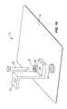
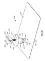
- FIG. 1is a top view of a roofing system according to some embodiments of the present invention.
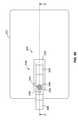
- FIG. 1Ais a cross-sectional view of the roofing system of FIG. 1 , taken along line A-A of FIG. 1 .
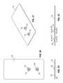
- FIG. 2is a top view of flashing from the roofing system shown in FIG. 1 .
- FIG. 3is a perspective view of the flashing shown in FIG. 2 .
- FIG. 4is a front view of the flashing shown in FIG. 2 .
- FIG. 5is a side view of the flashing shown in FIG. 2 .
- FIG. 6is a top view of a seal for use with the flashing shown in FIG. 2 .
- FIG. 6Ais a front view of an alternate seal for use with the flashing shown in FIG. 1 .
- FIG. 7is a cross-sectional view taken along line 7 - 7 shown in FIG. 6 .
- FIG. 7Ais a bottom perspective view of the seal shown in FIG. 6A .
- FIG. 8is a perspective view of the seal shown in FIG. 6 .
- FIG. 8Ais a top perspective view of the seal shown in FIG. 6A .
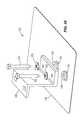
- FIG. 9is a top view of the flashing of FIG. 2 with the seal shown in FIG. 6 installed in the aperture.
- FIG. 10is a perspective view of the flashing and seal shown in FIG. 9 .
- FIG. 11is a front view of the flashing and seal shown in FIG. 9 .
- FIG. 12is a side view of the flashing and seal shown in FIG. 9 .
- FIG. 13is a side view of a bracket for use with the flashing and seal.
- FIG. 13Ais a side view of an alternative embodiment of the bracket.
- FIG. 14is a bottom view of the bracket shown in FIG. 13 .
- FIG. 14Ais a bottom view of the bracket shown in FIG. 13A .
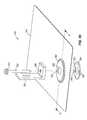
- FIG. 15is a top view of an assembly including the flashing, the seal, the bracket and a fastener.
- FIG. 16is a perspective view of the assembly shown in FIG. 15 .
- FIG. 17is a front view of the assembly shown in FIG. 15 .
- FIG. 18is a side view of the assembly shown in FIG. 15 .
- FIG. 19is an exploded view of the assembly shown in FIG. 15 .
- FIG. 20is a top view of a second embodiment of flashing according to the present invention.
- FIG. 21is a perspective view of the flashing shown in FIG. 20 .
- FIG. 22is a front view of the flashing shown in FIG. 20 .
- FIG. 23is a side view of the flashing shown in FIG. 20 .
- FIG. 24is a top view of the flashing shown in FIG. 20 including seals installed in the flashing apertures.
- FIG. 25is a perspective view of the flashing and seals shown in FIG. 24 .
- FIG. 26is a front view of the flashing and seals shown in FIG. 24 .
- FIG. 27is a side view of the flashing and seals shown in FIG. 24 .
- FIG. 28is a side view of a bracket for use with the flashing and seals shown in FIG. 24 .
- FIG. 28Ais a side view of an alternative embodiment of the bracket.
- FIG. 29is a bottom view of the bracket shown in FIG. 28 .
- FIG. 29Ais a bottom view of the bracket shown in FIG. 28A .
- FIG. 30is a top view of an assembly including the flashing, the seals, the bracket and two fasteners.
- FIG. 31is a perspective view of the assembly shown in FIG. 30 .
- FIG. 32is a front view of the assembly shown in FIG. 30 .
- FIG. 33is a side view of the assembly shown in FIG. 30 .
- FIG. 34is an exploded view of the assembly shown in FIG. 30 .
- FIG. 35is a top view of a third embodiment of flashing including one aperture.
- FIG. 36is a perspective view of the flashing shown in FIG. 35 .
- FIG. 37is a front view of the flashing shown in FIG. 35 .
- FIG. 38is a side view of the flashing shown in FIG. 35 .
- FIG. 39is a perspective view of the flashing shown in FIG. 35 including the seal shown in FIG. 6 .
- FIG. 40is a side view of a bracket for use with the flashing and seal shown in FIG. 35 .
- FIG. 41is a bottom view of the bracket shown in FIG. 40 .
- FIG. 42is a bottom perspective view of the bracket shown in FIG. 40 .
- FIG. 43is a top view of a fourth embodiment of flashing including one aperture.
- FIG. 44is a perspective view of the flashing shown in FIG. 43 .
- FIG. 45is a front view of the flashing shown in FIG. 43 .
- FIG. 46is a side view of the flashing shown in FIG. 43 .
- FIG. 47is a perspective view of an assembly including the flashing shown in FIG. 43 and a bracket.
- FIG. 48is a top perspective view of a bracket including a membrane exploded off of the bracket for clarity.
- FIG. 49is a bottom perspective of the bracket and membrane of FIG. 48 .
- FIG. 50is an exploded view of another roofing system embodiment.
- FIG. 51is a cross-sectional view of FIG. 50 , taken along line 51 - 51 of FIG. 50 .
- FIG. 52is a partial cross-sectional view of another roofing system embodiment.
- FIG. 53is a partial cross-sectional view of the roofing system of FIG. 52 with an alternative flashing arrangement.
- FIG. 54is a top view of a flashing and seal according to some independent embodiments of the present invention.
- FIG. 55is a cross-sectional view taken generally along line 55 - 55 of FIG. 54 and illustrating the seal.
- FIG. 56is an exploded view of the flashing and the seal of FIGS. 54 and 55 .
- FIG. 57is an alternate construction of the flashing shown in FIGS. 54-56 .
- FIG. 58is a top view of a flashing and the seal according to some independent embodiments of the present invention.
- FIG. 59is a cross-sectional view taken generally along line 59 - 59 of FIG. 58 and illustrating the seal.
- FIG. 60is a perspective view of a panel mounted to a track system for mounting to a roof surface.
- FIG. 61is a close-up perspective view of FIG. 60 with the panel shown in phantom, to more clearly illustrate the connection between the panel and the track system.
- FIG. 62is a side view of the panel and snow fence of FIGS. 60 and 61 .
- FIG. 63is a perspective view of a panel and a snow fence mounted to a track system for mounting to a roof surface.
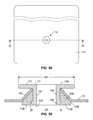
- FIG. 64is a cross-sectional view of the panel and snow fence taken along line 64 - 64 of FIG. 63 .
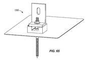
- FIG. 65is a perspective view of a structure for mounting the panel and snow fence to the roof without the use of a track that can be utilized with any of the embodiments disclosed herein.
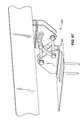
- FIG. 66is a side view of a first adjustable bracket shown in a first position in solid and a second position in phantom that can be utilized with any of the embodiments of the present invention.
- FIG. 67is a perspective view of the first adjustable bracket of FIG. 66 .
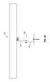
- FIGS. 68-70are various views of a second adjustable bracket that can be utilized with any of the embodiments of the present invention.
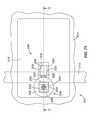
- FIG. 71is a top view of a roofing system according to some embodiments of the present invention.
- FIG. 72is a cross-sectional view of the roofing system of FIG. 71 , taken along line 72 - 72 of FIG. 71 .
- FIG. 73is a front view of a mounting assembly from the roofing system of FIGS. 71 and 72 .
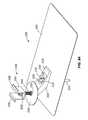
- FIG. 74is an exploded view of the mounting assembly of FIGS. 71-73 .
- FIG. 75is a top view of a mounting assembly according to some embodiments of the present invention.
- FIG. 76is a cross-sectional view of the mounting assembly of FIG. 75 , taken along line 76 - 76 of FIG. 75 .
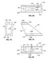
- FIG. 77is a front view of the mounting assembly of FIG. 75 .
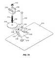
- FIG. 78is an exploded view of the mounting assembly of FIG. 75 .
- FIG. 79is an end view of a bracket according to some embodiments of the present invention.
- FIG. 80is a top view of the bracket of FIG. 79 .
- FIG. 81is a side view of the bracket of FIG. 79 .
- FIG. 82is a bottom view of the bracket of FIG. 79 .
- FIG. 83is a perspective view of the mounting assembly according to some embodiments of the present invention.
- FIG. 84is a perspective view of the mounting assembly of FIG. 83 and including an attachment bracket.
- FIG. 85is a perspective view of the mounting assembly of FIGS. 83 and 84 in an alternate orientation.
- FIG. 86is a top view of a mounting assembly according to some embodiments of the present invention.
- FIG. 87is a cross-sectional view of the mounting assembly of FIG. 86 , taken along line 87 - 87 of FIG. 86 .
- FIG. 88is a front view of the mounting assembly of FIG. 86 .
- FIG. 89is an exploded view of the mounting assembly of FIG. 86 .
- FIG. 90is a top view of a mounting assembly according to some embodiments of the present invention.
- FIG. 91is a front view of the mounting assembly of FIG. 90 .
- FIG. 92is a perspective view of the mounting assembly of FIG. 90 .
- FIG. 93is a side view of the mounting assembly of FIG. 90 .
- FIG. 94is an exploded view of the mounting assembly of FIG. 90 .
- phraseology and terminology used herein with reference to device or element orientationare only used to simplify description of embodiments of the present invention and do not alone indicate or imply that the device or element referred to must have a particular orientation.
- terms such as “first” and “second”are used herein for purposes of description and are not intended to indicate or imply relative importance or significance.
- FIGS. 1 and 1Aillustrate a roofing system 10 including a number of rafters or beams 12 , a roof substrate 14 (e.g., tarpaper, plywood or other decking material, insulation, and the like) supported on the rafters 12 , flashing 16 extending across the substrate 14 (i.e., placed immediately adjacent an upper surface of the substrate 14 or supported on one or more intermediate layers of roofing or sealing material, which in turn are placed on the substrate 14 ), a seal 18 , a mounting bracket 20 and at least one fastener 22 operable to connect the bracket 20 to the roof substrate 14 and the flashing 16 .
- the roofing system 10includes a washer 21 positioned between the mounting bracket 20 and the fastener 22 .
- the washer 21can be a spring washer, a compression lock washer, a sealing ring or the like. In some embodiments, the washer 21 is omitted.
- the roofing system 10is operable to support any of a variety of roof-mounted fixtures, such as, for example, snow fences, solar panels, an antenna, signs, billboards, or any of a number of other roof-mountable assemblies. Depending on one or more of the geographic location, anticipated quantity and type of precipitation, and anticipated roof and wind loading, the roofing system 10 can include any of a variety of flashing, seal and bracket arrangements, as will be discussed below.
- the bracket 20is operable to support any of a variety of roof-mounted fixtures, such as snow guards, snow fences, solar panels, an antenna, signs, billboards, or any other assembly mountable to a roof.
- roof-mounted fixturessuch as snow guards, snow fences, solar panels, an antenna, signs, billboards, or any other assembly mountable to a roof.
- apertures 24Prior to installation of the roofing system 10 , apertures 24 are drilled or otherwise created in the rafters 12 and/or substrate 14 .
- the illustrated embodimentshows apertures 24 in the substrate 14 .
- the roofing system 10inhibits leakage of fluids through the flashing 16 , and, in some embodiments, may also or alternately inhibit leakage of fluids beyond the flashing to portions of the substrate 14 or areas below the substrate 14 .
- the roofing system 10can be utilized on any of a variety of roof types, such as slate roofs, membrane roofs, aluminum roofs, standing seam roofs, tile roofs, shingle roofs, and the like.
- FIGS. 2-5A first embodiment of flashing 16 for the roofing system 10 is illustrated in FIGS. 2-5 .
- the flashing 16 of the embodiment of FIGS. 2-5extends substantially along a plane but includes an upwardly extending protrusion, such as the illustrated projection 30 that tapers upward, out of the plane.
- the upwardly extending projection 30has a first diameter d 1 in the plane, and a second diameter d 2 in a second plane that is substantially parallel to but spaced from the plane.
- the second diameter d 2is less than the first diameter d 1 , to form a truncated cone or frustoconical shape.
- the projections 30can have other shapes and configurations, corresponding to the shape of an underside of an associated mounting bracket 20 .
- the projection 30defines a concave interior side 26 , an exterior side 27 and a frustoconical end 28 .
- frustoconicalincludes cones with rounded, flat, non-flat or nearly flat upper portions and truncated cones with rounded, flat, non-flat or nearly flat upper portions.
- the projections 30can have a number of different shapes and configurations.
- the concave interior side 26 of the projection 30may have a number of different shapes and configurations, including but not limited to configurations in which the arch provided by the interior side 26 does not include a uniform radius.
- the concave interior side 26 and the flashing 16define a space therebetween.
- a sealcan be positioned within the space to at least partially fill the space to further inhibit leakage through the aperture 24 .
- the sealhas been omitted from FIG. 1A for clarity, but is illustrated and described in other embodiments. Any of the seals shown or described herein can be utilized with the roofing system shown in FIGS. 1 and 1A .
- the upwardly extending projection 30defines an aperture 32 positioned substantially in the second plane.
- the illustrated upwardly extending projection 30 and aperture 32are circular, but in other embodiments, can be square, D-shaped, triangular, pentagonal, hexagonal, ovular, or other regular or irregular shapes.
- the illustrated aperture 32is substantially centered on the upwardly extending projection 30 , but other, non-centered embodiments are possible.
- the flashing 16has a first side 34 and a second side 36 opposite the first side 34 .
- the first side 34 and the second side 36are substantially planar, apart from the projection 30 .
- the aperture 32is sized to receive a seal 18 therethrough.
- the seal 18can extend through the flashing 16 , such that the seal 18 engages or contacts the first side 34 of the flashing 16 and the second side 36 of the flashing 16 .
- the illustrated seal 18includes a first end portion 40 that forms a substantially circular disk having a planar end surface 41 and a second end portion 42 that forms a substantially circular disk having a planar end surface 43 substantially parallel to the planar end surface 41 .
- the illustrated seal 18also defines a stem, such as the illustrated tapered central portion 44 , extending between the first end portion 40 and the second end portion 42 .
- the tapered central portion 44has a first diameter d 3 adjacent the planar end surface 41 and a second diameter d 4 adjacent the planar end surface 43 .
- the first diameter d 3is less than the second diameter d 4 .
- the diameter of the tapered central portion 44increases from the first diameter d 3 to the second diameter d 4 substantially linearly to form a taper along a substantially constant angle.
- the seal 18has a substantially cylindrical overall shape, with a notch 45 cut out between the first end portion 40 and the second end portion 42 along the tapered central portion 44 .
- the notch 45is defined by a tapered surface 46 extending between the first and second end portions 40 , 42 .
- the second diameter d 4is approximately equal to the diameter of the first end portion 40 and the diameter of the second end portion 42 .
- the illustrated seal 18defines a substantially cylindrical aperture 48 that is substantially centrally located in the seal 18 .
- the aperture 48extends normal to the outside surfaces of the first and second end portions 40 , 42 and parallel to the substantially cylindrical overall shape of the seal 18 , in the illustrated embodiment.
- the aperture 48has a smaller diameter than the seal first diameter d 3 , as shown in FIG. 7 , so that the seal 18 has an adequate thickness between the first and second end portions 40 , 42 .
- the seal 18can be made from any suitable resilient sealing or elastomeric material, such as polymers, rubbers, plastics, and the like.
- the seal 18is insertable into the aperture 32 to couple the seal 18 to the flashing 16 , as illustrated in FIGS. 9-12 .
- the notch 45is sized to receive the flashing 16 therein.
- the seal 18is operable to form a compression seal by being held against the concave interior side 26 of the flashing 16 .
- the seal 18can be factory-installed in the flashing aperture 32 or can be inserted by on-site at a customer's building.
- a fixture for a punch presscan be sized to install the seals 18 into the respective apertures 32 .
- the punch presscan be utilized to form the projection 30 and the aperture 32 in flashing 16 , at the same time.
- the punch presscan form the projection 30 and the aperture 32 in the flashing 16 and then insert the seal 18 into the aperture 32 , either during the same operation or during a separate operation.
- a hand toolcan be utilized to insert the seal 18 into the aperture 32 .
- This toolcan be operated by a single user to press or otherwise urge the first end portion 40 through the aperture 32 , such that the projection 30 contacts the tapered surface 46 of the tapered central portion 44 .
- the toolcan include one or more fingers to engage the seal 18 and pull or push the seal 18 through the aperture 32 .
- the fingerscan be inserted through the aperture 32 from the flashing first side 34 toward the flashing second side 36 .
- the fingerscan then squeeze or pinch the first end portion 40 to temporarily reduce the diameter of the first end portion 40 .
- the fingerscan grasp a portion of the first end portion 40 .
- the first end portion 40is then pulled through the aperture 32 .
- the seal 18is resilient, such that the seal 18 returns to its previous shape and size after being inserted into the aperture 32 .
- FIGS. 6A-8AAn alternate seal 18 A is illustrated in FIGS. 6A-8A .
- the seal 18 Alike seal 18 can extend through the flashing 16 such that the seal 18 A engages or contacts the first side 34 of the flashing 16 and the second side 36 of the flashing 16 .
- the illustrated seal 18 Aincludes a first end portion 40 A and a second end portion 42 A, spaced from the first end portion 40 A.
- the first end portion 40 Ais tapered from a first diameter dA 1 outward to a second diameter dA 2 , which is greater than the first diameter dA 1 .
- the first end portion 40 A at the first diameter dA 1has a substantially planar end surface 41 A.
- the illustrated first end portion 40 Atapers along a constant slope, but in other embodiments, tapers of varying slope are possible.
- the second end portion 42 Ais tapered from a third diameter dA 3 inward to a location having a diameter which is less than the third diameter dA 3 .
- the second end portion 42 A at the third diameter dA 3has a substantially planar end surface 43 A, which is substantially parallel to the planar end surface 41 A, as shown in FIG. 6A .
- the illustrated second end portion 42 Atapers along a constant slope, but in other embodiments, tapers of varying slope are possible.
- the slope of the first end portion 40 Ais substantially identical to the slope of the second end portion 42 A. In other embodiments, the slope of the first end portion 40 A can be greater or less than the slope of the second end portion 42 A.
- the seal 18 Aincludes a central portion 44 A that is positioned between the first end portion 40 A and the second end portion 42 A.
- the central portion 44 Ais substantially disk-shaped and has a substantially constant diameter. In the illustrated embodiment, the central portion 44 A has a diameter equal to the second diameter dA 2 .
- the central portion 44 Aextends between the first end portion 40 A and the second end portion 42 A and defines a notch 45 A therebetween. The notch 45 A permits the first end portion 40 A to be compressed without compressing the second end portion 42 A.
- the seal 18 Acan define a substantially cylindrical aperture that is substantially centrally located in the seal 18 A, similar to the aperture 48 shown in seal 18 .
- the apertureextends normal to the planar end surfaces of the first and second end portions 40 A, 42 A, in the illustrated embodiment.
- the aperturecan have a smaller diameter than the seal first diameter dA 1 , so that the seal 18 A has an adequate thickness between the first and second end portions 40 A, 42 A.
- the aperturecan have a diameter equal to the dA 1 , such that the first end portion 40 A tapers upward toward the aperture.
- the aperturecan be formed only when a fastener is inserted through the flashing 16 and the seal 18 A during installation of the roofing system 10 . In other embodiments, the aperture can be formed in the seal prior to assembly of the roofing system 10 .
- the seal 18 Alike seal 18 , can be made from any suitable resilient sealing material, such as polymers, rubbers, and the like.
- the seal 18 Ais insertable into the aperture 32 in the flashing 16 to couple the seal 18 A to the flashing 16 .
- the first end portion 40 Aextends through the aperture 32 , such that the flashing 16 is positioned between the first end portion 40 A and the second end portion 42 A.
- the notch 45 Ais sized to receive the flashing 16 therein.
- a bracketsuch as the bracket 20 illustrated in FIGS. 13 and 14 , can be coupled to the seal 18 and flashing 16 .
- the illustrated bracket 20is generally z-shaped and includes an elongate body portion 52 having a first end 54 and a second end 56 spaced from the first end 54 .
- a first flange 58is coupled to the first end 54 and extends substantially perpendicular to the elongate body portion 52 in a first direction.
- a second flange 60is coupled to the second end 56 and extends substantially perpendicular to the elongate body portion 52 in a second direction, opposite the first direction.
- the first flange 58defines an aperture 62 extending substantially parallel to the elongate body portion 52 .
- the illustrated aperture 62is substantially ovular, but other shapes, such as circular, square, rectangular, hexagonal, and the like are possible.
- the aperture 62is sized to receive a fastener, protrusion, or the like therethrough.
- the ovular shape of the aperture 62permits flexibility and slight relative movement between the bracket 20 and the fastener, projection or the like, when installed.
- the second flange 60 of the bracket 20defines an aperture 64 that includes a first aperture portion 64 a and a second aperture portion 64 b .
- the first aperture portion 64 ahas a substantially cylindrical shape and defines a first diameter d 5 .
- the second aperture portion 64 bhas a substantially cylindrical shape and defines a second diameter d 6 that is less than the first diameter d 5 .
- the first aperture portion 64 ais sized to receive the seal first end portion 40 .
- the second aperture portion 64 bis sized to be smaller than the seal first end portion 40 to permit pre-loading of the seal 18 , to thereby seal the aperture 64 with the seal 18 .
- FIGS. 13A and 14AAn alternate embodiment of the bracket 20 A is shown in FIGS. 13A and 14A .
- the bracket 20 Adiffers from the bracket 20 in that the second flange 60 A includes an aperture 66 .
- the aperture 66includes a first aperture portion 66 a and a second aperture portion 66 b .
- the first aperture portion 66 ahas a substantially constant diameter da.
- the second aperture portion 66 bhas a variable, tapering diameter starting at diameter db, which is less than da and tapering inward to diameter dc. Diameter dc is less than either da or db.
- the second aperture portion 66 bhas a substantially constant slope at which the diameter changes between db and dc.
- the aperture 66is tapered along the entire distance between da and dc. In other embodiments, diameters da and db are substantially equal. In still other embodiments, the slope of the tapered portion 66 b is greater or less than the illustrated slope. In yet other embodiments, the relative heights of the first aperture portion 66 a and the second aperture portion 66 b are variable.
- the projection 30 in the flashing 16is sized to receive the second end portion 42 A, as discussed above.
- the aperture 66is sized to receive the seal 18 A and at least partially pre-load the seal 18 A to enhance the seal between the seal 18 and the bracket 20 A.
- a differently shaped sealcan be utilized.
- One such seal 18 Ais illustrated in FIGS. 6A and 7A .
- the seal 18 Ais sized to substantially mate with the aperture 66 , such that the aperture 66 can slightly pre-load the seal 18 A.
- the first aperture portion 66 ais sized to receive the central portion 44 A, such that da is substantially equal to or slightly less than dA 2 .
- the central portion 44 Acan be slightly tapered to permit insertion into the first aperture portion 66 a when da is slightly less than dA 2 .
- the aperture portion 66 bis sized to receive the first end portion 40 A, such that dc is substantially equal to or slightly less than dA 1 , and db is substantially equal to or slightly less than dA 2 . In embodiments where dc and db are slightly less than dA 1 and dA 2 , respectfully, slight pre-loading occurs when the seal 18 A is pressed into the aperture 66 .
- the seal 18 Acan be preloaded by pressing the seal 18 A into the bracket 20 A by use of a fastener and the shape and size of the projection 30 in the flashing 16 .
- seals 18 and 18 Acan be inserted into either or both apertures 64 or 66 , and other configurations and arrangements of seals and apertures can be utilized to achieve the desired seal between the flashing 16 and the bracket 20 or 20 A.
- One or more fastenerscan be used to couple the bracket 20 to the seal 18 and flashing 16 to form a roofing assembly.
- One such assembly 70is illustrated in FIGS. 15-19 and includes the flashing 16 , the seal 18 , the bracket 20 , one fastener 22 , and a washer 72 .
- the washer 72can be a polymeric compression washer to provide a substantially water-tight seal between the fastener 22 and the bracket aperture 64 .
- the washer 72can be omitted or can be replaced by an o-ring or an applied sealant, such as caulk.
- the washer 72can include a stiffening element, such as, for example, a rigid backing, to provide additional support.
- the assembly 70can be installed on a roof.
- the fastener 22can extend through the flashing 16 , the seal 18 , the bracket 20 , into the substrate 14 and the rafters 12 , as illustrated in FIGS. 1 and 1A .
- the washer 72 and the seal 18work together to prevent or inhibit entry of water or other fluid into the aperture 64 or to the rafters 12 and/or substrate 14 .
- the illustrated fastenersare bolts, other fasteners, such as screws, studs, nails, and other removable and non-removable fasteners, can be used.
- a similar assemblycan be formed with the seal 18 A and the bracket 20 A.
- This assemblycan also include a fastener 22 and a washer 72 , as described above.
- the seals 18 , 18 Acan be used interchangeably with brackets 20 , 20 A, and other shapes and arrangements of seals and brackets are possible.
- FIGS. 20-34illustrate another embodiment of a roofing system 110 according to the present invention.
- This embodimentemploys much of the same structure and has many of the same properties as the embodiments of the roofing system 10 described above in connection with FIGS. 1-19 . Accordingly, the following description focuses primarily upon structure and features that are different than the embodiments described above in connection with FIGS. 1-19 . Reference should be made to the description above in connection with FIGS. 1-19 for additional information regarding the structure and features, and possible alternatives to the structure and features of the roofing system 110 illustrated in FIGS. 20-34 and described below.
- Features and elements in the embodiment of FIGS. 20-34 corresponding to features and elements in the embodiments described above in connection with of FIGS. 1-19are numbered in the 100 series of reference numbers.
- the second flashing 116is substantially in the shape of a rectangular sheet having rounded corners.
- the flashing 116extends substantially along a plane but includes a first upwardly extending projection 130 that tapers upwardly, out of the plane.
- the first upwardly extending projection 130has a first diameter d 7 in the plane, and a second diameter d 8 in a second plane that is substantially parallel to but spaced from the plane.
- the second diameter d 8is less than the first diameter d 7 , to form a truncated cone or frustoconical shape.
- the diameters d 7 and d 8can be the same as or different than the diameters d 1 and d 2 of the projection 30 described above.
- the primary difference between the roofing system 110 embodiment illustrated in FIGS. 20-34 and the roofing system embodiment 10 illustrated in FIGS. 1-19is that the roofing system 110 includes a second upwardly extending projection 131 in the flashing 116 .
- the second upwardly extending projection 131has a first diameter d 9 in the plane, and a second diameter d 10 in a second plane that is substantially parallel to but spaced from the plane.
- the second diameter d 10is less than the first diameter d 9 , to form a truncated cone or frustoconical shape.
- the diameters d 9 and d 10can be the same as or different than the diameters d 7 and d 8 of the first projection 130 described above.
- Each of the upwardly extending projections 130 , 131defines an aperture 132 , 133 positioned substantially in the second plane.
- the illustrated projections 130 , 131are substantially the same size and shape as the projection 30 , but can have different shapes and configurations. Alternatively, each of the projections 130 , 131 can have a different shape or configuration so as to require the corresponding mounting bracket 120 to be installed in a specific desired orientation relative to the flashing 116 .
- the illustrated upwardly extending projections 130 , 131 and respective apertures 132 , 133are circular, but in other embodiments, can be square, triangular, pentagonal, hexagonal, ovular, or other regular or irregular shapes.
- the illustrated apertures 132 , 133are substantially centered on the respective upwardly extending projections 130 , 131 , but other, non-centered embodiments are possible.
- the second flashing 116has a first side 134 and a second side 136 opposite the first side 134 .
- the first side 134 and the second side 136are substantially planar apart from the projections 130 , 131 .
- First and second seals 118 , 119can be inserted into respective apertures 132 , 133 , as described above and as illustrated in FIGS. 24-27 .
- a seal similar to seal 18 Acan be inserted into the flashing 116 .
- Other aperture 132 , 133 and seal configurationsare possible and are considered to be within the scope of the present invention.
- the seals 118 , 119can be inserted into the respective apertures 132 , 133 as discussed above, such as with a punch press, a hand tool, or the like.
- a bracketsuch as the bracket 120 illustrated in FIGS. 28 and 29 , can be coupled to the seals 118 , 119 and flashing 116 .
- the illustrated bracket 120is generally z-shaped and includes an elongate body portion 152 having a first end 154 and a second end 156 spaced from the first end 154 .
- a first flange 158is coupled to the first end 154 and extends substantially perpendicular to the elongate body portion 152 in a first direction.
- a second flange 160is coupled to the second end 156 and extends substantially perpendicular to the elongate body portion 152 in a second direction, opposite the first direction.
- the first flange 158defines a pair of apertures 162 , 163 extending substantially parallel to the elongate body portion 152 .
- the illustrated apertures 162 , 163are substantially ovular, but other shapes, such as circular, square, rectangular, hexagonal, and the like are possible.
- the apertures 162 , 163are sized to receive a fastener, projection, or the like therethrough.
- the ovular shape of the apertures 162 , 163permits flexibility and slight relative movement between the bracket 120 and the fastener, projection or the like, when installed.
- the second flange 160 of the bracket 120defines a first aperture 164 that includes a first aperture portion 164 a and a second aperture portion 164 b .
- the second flange 160 of the bracketfurther defines a second aperture 165 that includes a first aperture portion 165 a and a second aperture portion 165 b .
- the first aperture portions 164 a , 165 ahave a substantially cylindrical shape and define a first diameter d 11 .
- the second aperture portions 164 b , 165 bhave a substantially cylindrical shape and define a second diameter d 12 that is less than the first diameter d 11 .
- the first aperture portions 164 a , 165 aare sized to receive the seal 118 .
- the second aperture portions 164 b , 165 bare sized to be smaller than the seal 118 , to permit pre-loading of the seal 118 , to thereby seal the aperture 164 with the seal 118 .
- the apertures 164 , 165can have the same shape and size as aperture 64 , or can be larger than or smaller than the aperture 64 .
- First aperture portions 164 a , 165 acan have different diameters to denote proper orientation of the bracket 120 on the flashing 116 .
- Other configurations and arrangement of brackets and aperturesare possible and are considered to be within the scope of the present invention.
- FIGS. 28A and 29AAn alternate embodiment of the bracket 120 A is shown in FIGS. 28A and 29A .
- the bracket 120 Ais similar to the bracket 120 shown in FIGS. 28 and 29 , such that items include the indicator “A” to denote the similarity.
- the bracket 120 Adiffers from the bracket 120 in that the second flange 160 A includes apertures 166 and 167 .
- the apertures 166 , 167have a variable, tapering diameter starting at diameter dd, and tapering inward to diameter de. Diameter dc is less than da.
- the apertures 166 , 167have a substantially constant slope at which the diameter changes between da and dc. In some embodiments, the apertures 166 , 167 are tapered along only a portion of the distance between da and dc. In still other embodiments, the slopes of the respective apertures 166 , 167 are greater or less than the illustrated slope.
- the apertures 166 , 167can have the same diameters dd,
- the apertures 166 , 167are sized to receive a seal similar to seal 18 A, illustrated in FIGS. 6A-8A , and at least partially pre-loading the seal 18 A to enhance the seal between the seal 18 and the bracket 20 A.
- a differently shaped sealcan be utilized.
- the seals 118 , 119 or other similar sealscan be inserted into either apertures 164 , 165 or 166 , 165 .
- Other configurations and arrangements of seals and aperturescan be utilized to achieve the desired seal between the flashing 116 and the bracket 120 or 120 A.
- One or more fastenerscan be used to couple the bracket 120 , 120 A to the seals 118 , 119 and flashing 116 to form a roofing assembly.
- One such assembly 170is illustrated in FIGS. 30-34 and includes the flashing 116 , the seals 118 , 119 , the bracket 120 , two fasteners 122 , 123 and two washers 172 , 173 .
- the washers 172 , 173can be polymeric compression washers to provide a substantially water-tight seal between the fastener 122 , 123 and the bracket apertures 164 , 165 .
- the washers 172 , 173can be omitted or can be replaced by an o-ring or an applied sealant, such as caulk.
- the assembly 170can be installed on a roof.
- the fasteners 122 , 123can extend through the flashing 116 , the respective seals 118 , 119 , the bracket 120 , and into rafters or substrate similar to the embodiment illustrated in FIGS. 1 and 1A .
- the washers 172 , 173 and the seals 118 , 119work together to prevent or inhibit entry of water or other fluid into the apertures 164 , 165 or the rafters 12 and/or substrate 14 .
- the illustrated fastenersare bolts, other fasteners, such as screws, studs, nails, and other acceptable removable and non-removable fasteners, can be used.
- the bracket 120is operable to support any of a variety of roof-mounted fixtures, such as snow guards, snow fences, solar panels, an antenna, signs, billboards, walkways, pipe lines, mechanical units, signage, screens, cabling or any other assembly mountable to a roof.
- the inclusion of two projections 130 , 131can be beneficial to inhibit rotation of a bracket 120 while mounted on a roof and/or to define a specific orientation of a bracket 120 relative to the roof.
- Other bracket configurations and arrangementsare possible, and the illustrated bracket 120 is provided by way of example only.
- bracket 20can be coupled to only one projection 130 , 131 , such that the brackets 20 can have different orientations, and the unused projection can be sealed with other structure.
- a similar assemblycan be formed with the seal 118 A, 119 A and the bracket 120 A.
- This assemblycan also include a pair of fasteners 122 , 123 and washers 172 , 173 , as described above.
- the seals 118 , 118 A, 119 , 119 Acan be used interchangeably with brackets 120 , 120 A, and other shapes and arrangements of seals and brackets are possible.
- FIGS. 35-42illustrate another embodiment of a roofing system 210 according to the present invention.
- This embodimentemploys much of the same structure and has many of the same properties as the embodiments of the roofing systems 10 , 110 described above in connection with FIGS. 1-34 . Accordingly, the following description focuses primarily upon structure and features that are different than the embodiments described above in connection with FIGS. 1-34 . Reference should be made to the description above in connection with FIGS. 1-34 for additional information regarding the structure and features, and possible alternatives to the structure and features of the roofing system 210 illustrated in FIGS. 35-42 and described below.
- Features and elements in the embodiment of FIGS. 35-42 corresponding to features and elements in the embodiments described above in connection with of FIGS. 1-34are numbered in the 200 series of reference numbers.
- a third flashing 216is illustrated in FIGS. 35-39 .
- the third flashing 216is substantially in the shape of a rectangular sheet having square corners.
- the flashing 216extends substantially along a plane but includes a first upwardly extending projection 230 that tapers upwardly, out of the plane.
- the first upwardly extending projection 230has a first diameter d 13 in the plane, and a second diameter d 14 in a second plane that is substantially parallel to but spaced from the plane.
- the second diameter d 14is less than the first diameter d 13 , to form a truncated cone or frustoconical shape.
- the diameters d 13 and d 14can be the same as or different than the diameters d 1 and d 2 of the projection 30 described above.
- the first upwardly extending projection 230defines an aperture 232 positioned substantially in the second plane.
- the illustrated upwardly extending projection 230 and aperture 232are circular, but in other embodiments, can be square, triangular, pentagonal, hexagonal, ovular, or other regular or irregular shapes.
- the illustrated aperture 232is substantially centered on the upwardly extending projection 230 , but other, non-centered embodiments are possible.
- the third flashing 216has a first side 234 and a second side 236 opposite the first side 234 .
- the first side 234 and the second side 236are substantially planar apart from the projection 230 .
- the third flashing 216also includes a second upwardly extending projection 276 extending out of the first plane around a majority of the circumference of the first projection 230 .
- the second upwardly extending projection 276has a substantially curved shape and forms almost a complete ring around the first projection 230 .
- the second projection 276forms a channel, slit or other similar narrow aperture or path, such as the illustrated slit 278 .
- the slit 278can be oriented vertically below the upwardly extending projection 276 to provide a pathway for moisture to move away from the projection 230 . Moisture can be moved or drawn away from the aperture 232 by at least one of wicking, capillary action, surface tension, gravity, and evaporation.
- the slit 278is positioned on a downhill side of the roof relative to the aperture 232 to utilize gravity to move fluid away from the projection 230 .
- the projection 276can further direct fluid away from the projection 230 to inhibit leakage of water into the aperture 232 .
- the slit 278includes a cutout or downwardly protruding extension to further move fluid away from the projection 230 and aperture 232 .
- first and second projections 230 , 276can be formed together on a second sheet of flashing or other similar material, and the second sheet can then be secured (i.e., welded, brazed, soldered, glued or fastened in another conventional manner) to the flashing 216 .
- FIG. 39illustrates a seal 218 inserted into the aperture 232 , similar to the embodiments described above for seals 18 and 118 .
- the seal 218can contact both the first side 234 and the second side 236 of the flashing 216 .
- the seal 218can be inserted into the apertures 232 in any of the methods described above.
- the projection 230 , aperture 232 , and projection 276can be formed into the flashing 216 during the same operation or by the same machine as when the seal 218 is inserted into the aperture 232 . In other embodiments, the projections 230 , 276 and aperture 232 can be formed into the flashing 216 prior to inserting the seal 218 into the aperture 232 .
- the slit 278 and projection 276are shown in FIG. 39 more clearly, so as to illustrate the height difference between the flashing plane, the projection 230 and the projection 276 .
- seal 218would inhibit the fluid from entering the aperture 232 .
- the brackets 20 , 20 A, 120 , 120 Acan be utilized with the embodiment shown in FIGS. 35-42 .
- a bracket 220as shown in FIGS. 40-42 , can be also or alternatively be utilized with the flashing 216 .
- the bracket 220is generally z-shaped and includes an elongate body portion 252 having a first end 254 and a second end 256 spaced from the first end 254 .
- a first flange 258is coupled to the first end 254 and extends substantially perpendicular to the elongate body portion 252 in a first direction.
- a second flange 260is coupled to the second end 256 and extends substantially perpendicular to the elongate body portion 252 in a second direction, opposite the first direction.
- the first flange 258defines an aperture 262 extending substantially parallel to the elongate body portion 252 .
- the illustrated aperture 262is substantially ovular, but other shapes, such as circular, square, rectangular, hexagonal, and the like are possible.
- the aperture 262is sized to receive a fastener, projection, or the like therethrough.
- the ovular shape of the aperture 262permits flexibility and slight relative movement between the bracket 220 and the fastener, projection or the like, when installed.
- the second flange 260 of the bracket 220defines an aperture 268 that includes a first aperture portion 268 a , a second aperture portion 268 b , and a third aperture portion 268 c .
- the first aperture portion 268 ahas is substantially ring-shaped and defines a first diameter d 15 .
- the second aperture portion 268 bhas a substantially cylindrical shape and defines a second diameter d 16 that is less than the first diameter d 15 .
- the third aperture portion 286 cis substantially circular and has a third diameter d 17 that is less than the first and second diameters d 15 and d 16 .
- a downwardly protruding annular flange 282extends between the first aperture portion 268 a and the second aperture portion 268 b .
- the first aperture portion 268 ais sized to receive the second projection 276 .
- the downwardly protruding annular flange 282is substantially planar with a distal surface of the second flange 260 of the bracket 220 .
- the second projection 276 and the downwardly protruding annular flange 282substantially mate, such that the downwardly protruding annular flange 282 contacts the flashing 216 between the first projection 230 and the second projection 276 .
- the second aperture portion 268 bis sized to be smaller than the seal 218 to permit pre-loading of the seal 218 , to thereby seal the aperture 268 with the seal 218 .
- the first aperture portion 268 a , the downwardly protruding annular flange 282 and the second aperture portion 268 b , projection 230 and seal 218work together to form a labyrinth seal to inhibit entry of fluid into the aperture 232 .
- a notch, channel, recess, or the like, such as the illustrated notch 284can be defined in the bracket second flange 260 .
- the notch 284is in fluid communication with the first aperture portion 268 a .
- the fluidis permitted to flow out through the slit 278 and/or the notch 284 .
- the slit 278 and notch 284are substantially aligned and positioned on a downhill side of the roof relative to the projection 230 . Gravity is then used to move fluid away from the aperture 232 via the slit 278 and/or notch 284 to further inhibit entry of fluid through aperture 232 .
- Other sizes, shapes, quantities, and configurations of notchescan be utilized in combination with the bracket 220 .
- the bracket 220can be utilized in the above described embodiments in place of bracket 20 and 120 .
- the brackets 20 and/or 120can include a notch similar to the illustrated notch 284 to provide a path for fluid to flow away from the respective apertures 32 , 132 , 133 .
- the bracket 220can further include a tapered portion, similar to the tapered portions of brackets 20 A and 120 A.
- the bracket 220 with a tapered portioncan be utilized in place of brackets 20 A and 120 A and can be shaped to mate with seal 18 A.
- the brackets 20 A and/or 120 Acan include a notch similar to the illustrated notch 284 to provide a path for fluid flow away from the respective apertures 32 , 132 , 133 .
- FIGS. 43-47illustrate another embodiment of a roofing system 310 according to the present invention.
- This embodimentemploys much of the same structure and has many of the same properties as the embodiments of the roofing systems 10 , 110 , 210 described above in connection with FIGS. 1-42 . Accordingly, the following description focuses primarily upon structure and features that are different than the embodiments described above in connection with FIGS. 1-42 . Reference should be made to the description above in connection with FIGS. 1-42 for additional information regarding the structure and features, and possible alternatives to the structure and features of the roofing system 310 illustrated in FIGS. 43-47 and described below.
- Features and elements in the embodiment of FIGS. 43-47 corresponding to features and elements in the embodiments described above in connection with of FIGS. 1-42are numbered in the 300 series of reference numbers.
- FIGS. 43-47illustrate a fourth flashing 316 associated with the present invention.
- the fourth flashing 316is substantially in the shape of a rectangular sheet having square corners.
- the flashing 316extends substantially along a plane but includes an upwardly extending projection 330 that tapers upward, out of the plane.
- the upwardly extending projection 330has a first diameter d 17 in the plane, and a second diameter d 18 in a second plane that is substantially parallel to but spaced from the plane.
- the second diameter d 18is less than the first diameter d 17 , to form a truncated cone or frustoconical shape.
- the diameters d 17 and d 18can be the same as or different than the diameters d 1 and d 2 of the projection 30 described above.
- the projection 330can define an aperture 332 positioned substantially in the second plane.
- the illustrated upwardly extending projection 330 and aperture 332are circular, but in other embodiments, can be square, triangular, pentagonal, hexagonal, ovular, or other regular or irregular shapes.
- the illustrated aperture 332is substantially centered on the upwardly extending projection 330 , but other, non-centered embodiments are possible.
- the fourth flashing 316has a first side 334 and a second side 336 opposite the first side 334 .
- the first side 334 and the second side 336are substantially planar apart from the projection 330 .
- the flashing 316can further define other non-planar features, such as a trench 386 extending circumferentially around the projection 330 and a channel 388 , extending between the trench 386 and an edge of the flashing 316 .
- the trench 386can provide a pathway for fluid around the projection 330 to inhibit fluid flow up the projection 330 , similar to the function of the projection ridge 276 shown in FIGS. 35-39 .
- the channel 388can provide a pathway for fluid to move away from the projection 330 , similar to the function of the slit 278 shown in FIGS. 35-39 .
- Moisturecan be moved or drawn away from the aperture 232 by at least one of wicking, capillary action, surface tension, gravity, and evaporation.
- the channel 388is positioned on a downhill side of the roof relative to the aperture 332 to utilize gravity to move fluid away from the projection 330 .
- the trench 386can further direct fluid away from the projection 330 to inhibit leakage of water into the aperture 232 .
- the channel 388includes a cutout, scoring or downwardly protruding extension that extends a portion of the way to the edge of the flashing to further move fluid away from the projection 330 and aperture 332 .
- a sealsuch as seal 18 , 18 A, 118 or 218 can be inserted into the aperture 332 , similar to the embodiments described above for seals 18 , 18 A, 118 , and 218 .
- the sealcan contact both the first side 334 and the second side 336 of the flashing 316 . In the instance that fluid would flow past the trench 386 and up the projection 330 , seal 318 would inhibit the fluid from entering the aperture 332 .
- the sealcan be inserted into the apertures 332 using any of the methods described above.
- the projection 330 , aperture 332 , trench 386 , and channel 388can be formed into the flashing 316 during the same operation or by the same machine as when the seal is inserted into the aperture 332 .
- the projection 330 , trench 386 , channel 388 , and aperture 432can be formed into the flashing 316 prior to inserting the seal into the aperture 332 .
- a bracket 320can be coupled to the flashing 316 .
- a bracket similar to bracket 20is shown, any of the above-described brackets, such as 20 , 20 A, 120 , 120 A or 220 , can be utilized with the flashing 316 .
- the flashing 316can define two projections and thereby two trenches and a channel joining the trenches and extending to an edge of the flashing 316 .
- the flashing 316can define two projections and two trenches, such that each trench joins a separate channel and each channel separately extends to an edge of the flashing 316 .
- Other combinations and configurations of projections, slits, trenches and channelscan be utilized within the scope of the present invention.
- FIGS. 48 and 49illustrate another embodiment of a bracket 420 according to the present invention.
- This embodimentemploys much of the same structure and has many of the same properties as the embodiments of the brackets 20 , 20 A, 120 , 120 A, 220 or 320 described above in connection with FIGS. 1-47 . Accordingly, the following description focuses primarily upon structure and features that are different than the embodiments described above in connection with FIGS. 1-47 . Reference should be made to the description above in connection with FIGS. 1-47 for additional information regarding the structure and features, and possible alternatives to the structure and features of the bracket 420 illustrated in FIGS. 48 and 49 and described below.
- Features and elements in the embodiment of FIGS. 48 and 49 corresponding to features and elements in the embodiments described above in connection with of FIGS. 1-47are numbered in the 400 series of reference numbers.
- FIGS. 48 and 49illustrate a bracket 420 similar to the bracket 20 A shown in FIGS. 13A and 14A .
- the bracket 420further includes a flexible membrane 490 coupled thereto adjacent aperture 466 .
- the aperture 466can be sized to receive the flexible membrane 490 in a first aperture portion 466 a , that has a diameter substantially equal to a diameter of the flexible membrane 490 .
- the aperture 466can further include a second aperture portion 466 b that is substantially tapered or frustoconical and has first and second diameters, both of which are less than the membrane diameter.
- the flexible membrane 490can be permanently or removably coupled to the bracket 420 .
- the flexible membrane 490can be affixed to the bracket 420 by a suitable adhesive.
- a protective sheet or “sticker”is affixed to the flexible membrane 490 to protect the membrane 490 during manufacturing and shipping. The sticker is then removed from the membrane 490 prior to installation.
- the flexible membrane 490can comprise a polymer, rubber, plastic or other suitable elastomeric material.
- the bracket 420can be coupled to any of the above-described flashing 16 , 116 , 216 or 316 or any other suitable flashing.
- the aperture 466is sized to receive at least one of a projection and a seal, such as any of the projections and seals described herein.
- the flexible membrane 490can deform around a projection without rupturing or cracking In some embodiments, the flexible membrane 490 is used in place of a seal because the flexible membrane 490 sufficiently seals the aperture 466 .
- a fastenersuch as any of the fasteners illustrated and described herein can be inserted into the flexible membrane 490 to form an aperture in the flexible membrane 490 .
- the flexible membrane 490is operable to substantially retain its shape and resist further tearing or ripping.
- the flexible membrane 490can closely adhere to the fastener to substantially seal the aperture 466 .
- a flexible membranecan be coupled to the bracket adjacent each aperture, whereas in other embodiments, a single flexible membrane can be coupled to the bracket covering both apertures.
- FIGS. 50 and 51illustrate another embodiment of a roofing system 510 according to the present invention.
- This embodimentemploys much of the same structure and has many of the same properties as the embodiments of the roofing systems described above in connection with FIGS. 1-49 . Accordingly, the following description focuses primarily upon structure and features that are different than the embodiments described above in connection with FIGS. 1-49 . Reference should be made to the description above in connection with FIGS. 1-49 for additional information regarding the structure and features, and possible alternatives to the structure and features of the roofing system 510 illustrated in FIGS. 50 and 51 and described below.
- Features and elements in the embodiment of FIGS. 50 and 51 corresponding to features and elements in the embodiments described above in connection with of FIGS. 1-49are numbered in the 500 series of reference numbers.
- FIGS. 50 and 51illustrate another roofing system 510 including flashing 516 , a bracket 520 , a fastener 522 , and a compression washer 572 .
- the flashing 516is formed of a rigid or semi-rigid material and includes a first projection 530 similar to the previously-described projections 30 , 130 , 230 , and 330 .
- the flashing 516can be elastic or membranous, or alternatively, rigid or semi-rigid flashing can be supplemented with a flexible membrane.
- the flexible membranecan be similar to the flexible membrane 490 or can extend over substantially the entire surface area of the flashing 516 .
- the flexible membranecan comprise a polymer, rubber, plastic or other similar material.
- the projections 530 and 592need not be formed into the flexible membrane. Rather, the flexible membrane can stretch and conform to the base 594 to include projections similar in shape and size to projections 530 and 592 .
- the flashing 516further includes a second projection 592 that extends in substantially the same direction as the first projection 530 .
- the second projection 592can be substantially circular, as illustrated, or can be ovular, square, rectangular, triangular, or other regular or non-regular shape.
- the second projection 592is sized to at least partially receive or engage a rigid base 594 between the flashing 516 and a roof substrate.
- the first and/or second projections 530 , 592can be formed when the flashing 516 is draped across the base 594 .
- the illustrated base 594is substantially circular, but can be ovular, square, rectangular, triangular or other regular or non-regular shapes.
- the geometry of the base 594can correspond with the geometry of the second projection 592 , or as mentioned above, can cause the flashing 516 to be formed around the contours of the base 594 such that the flashing 516 matingly engages the base 594 .
- the base 594can include at least one tooth 596 depending downwardly therefrom.
- the illustrated base 594includes three teeth 596 extending away from the flashing 516 .
- the teeth 596can bear against or grip a roof substrate to inhibit movement of the flashing 516 with respect to the roof substrate.
- a usercan press, push or pound the base 594 against the roof substrate, such as with a hammer.
- the base 594retains the flashing 516 against the roof substrate to limit or eliminate gaps created by movement of the flashing 516 relative to the roof, roof substrate, and the like.
- the base 594further permits the fastener 522 to be tightened against the flashing 516 and the bracket 520 without denting, deforming or damaging the flashing 516 .
- the illustrated base 594further includes an aperture 598 and a projection 500 through which the aperture 598 extends.
- the illustrated aperture 598 and projection 500are substantially centered on the base 594 .
- the aperture 598is sized to receive the fastener 522 and can be the same size or a similar size as aperture 532 .
- the illustrated projection 500extends into the space provided by the projection 530 , and substantially mates with the projection 530 , such that projections 530 and 500 extend together.
- the projections 530 and 500work together to inhibit relative movement of the flashing 516 with respect to the roof.
- the illustrated bracket 520is substantially L-shaped and includes an elongate body portion 552 and a first flange 558 .
- the illustrated elongate body portion 552includes an aperture 569 that is sized to receive a fastener to support at least one of a snow guard, a snow fence, a solar panel, an antenna, a sign, and a billboard, or related components.
- the illustrated first flange 558includes a tapered aperture 566 that is sized to at least partially receive the first projection 530 and the washer projection 500 .
- the tapered aperture 566is also sized to receive the fastener 522 therethrough.
- the compression washer 572includes a washer and a seal, such as an o-ring.
- the fastener 522has a head that bear against the washer and the washer bears against the o-ring to provide a resilient seal between the fastener head and the bracket 520 .
- FIGS. 52 and 53illustrate another embodiment of a roofing system 610 according to the present invention.
- This embodimentemploys much of the same structure and has many of the same properties as the embodiments of the roofing systems described above in connection with FIGS. 1-51 . Accordingly, the following description focuses primarily upon structure and features that are different than the embodiments described above in connection with FIGS. 1-51 . Reference should be made to the description above in connection with FIGS. 1-51 for additional information regarding the structure and features, and possible alternatives to the structure and features of the roofing system 610 illustrated in FIGS. 52 and 53 and described below.
- Features and elements in the embodiment of FIGS. 52 and 53 corresponding to features and elements in the embodiments described above in connection with of FIGS. 1-51are numbered in the 600 series of reference numbers.
- FIGS. 52 and 53illustrate a roofing system 610 that includes a piece of flashing 616 defining an aperture 632 therethrough.
- the flashing aperture 632defines a diameter d 19 in FIG. 52 and diameter d 20 in FIG. 53 .
- the diameter d 19 of FIG. 52is greater than the diameter d 20 of FIG. 53 .
- the flashing 616can include a projection defining a substantially frustoconical shape, similar to the projections described above.
- the roofing system 610further includes a roof bracket 620 , which can include any of the previously-illustrated and described brackets.
- the illustrated bracket 620is only partially shown, to more clearly illustrate the details of the engagement between the bracket 620 and the flashing 616 .
- the illustrated bracket 620includes an aperture 671 extending through the bracket 620 and having a substantially frustoconical shape.
- the roofing system 610also includes a seal 618 having a generally frustoconical shape and defining an aperture 648 extending therethrough.
- the seal 618has a first narrow end 641 that defines a narrow seal diameter d 21 and a second wide end 643 that defines a wide seal diameter d 22 .
- the narrow seal diameter d 21is less than the wide seal diameter d 22 .
- the first narrow endis spaced from the roof surface and the second wide end is proximate to or adjacent to the roof surface.
- the roofing system 610further includes at least one fastener, such as the illustrated fastener 622 .
- the fastener 622can be any threaded or unthreaded fastener suitable to retain the roofing system 610 on a roof.
- the fastener 622extends through the flashing aperture 632 , the seal aperture 648 , and the bracket aperture 671 .
- the fastener 622has a fastener diameter d 23 , that is less than the flashing diameter d 19 of FIG. 52 and is less than or substantially equal to the flashing diameter d 20 of FIG. 53 .
- the diameter of the fastener 622is less than or substantially equal to the narrow seal diameter d 21 and is less than the wide seal diameter d 22 .
- the seal aperture 648can be sized to receive the fastener 622 and to optionally form a substantially water-tight seal with the fastener 622 .
- the roofing system 610can further include a washer 672 , as illustrated in FIG. 53 .
- the washer 672can be included in the embodiment of FIG. 52 , or could be omitted from the embodiment illustrated in FIG. 53 .
- the washer 672can be a polymeric compression washer to provide a substantially water-tight seal between the fastener 622 and the bracket aperture 671 .
- the washer 672can be omitted or can be replaced by an o-ring or an applied sealant, such as caulk.
- the washer 672can include a stiffening element, such as, for example, a rigid backing, to provide additional support.
- the washer 672can have an aperture that defines an diameter that is larger than or substantially equal to the diameter of the fastener 622 .
- FIG. 53illustrates possible leak points of the roofing system 610 .
- a first possible leak point Ais between the head of the fastener 622 and the washer 672 .
- a second possible leak point Bis between the washer 672 and the bracket 620 .
- a third possible leak point Cis between the bracket 620 and the flashing 616 .
- the washer 672 , the fastener 622 , the bracket 620 and the seal 618work together to substantially inhibit or prevent flow of fluid through first and second leak points A, B.
- the bracket 620 , the seal 618 and the flashing 616work together to substantially inhibit or prevent flow of fluid through the third leak point C.
- FIGS. 54-56illustrate an alternative seal arrangement that can be used with any of the above-described applications.
- FIGS. 54-56illustrate flashing 716 having a protrusion 730 defining an aperture 732 and a seal 718 extending therethrough.
- the flashing 716includes a first surface 734 and a second surface 736 opposite the first surface 734 .
- the seal 718includes a first seal member 718 A and a second seal member 718 B.
- the first seal member 718 Asubstantially mates with the second seal member 718 B to have substantially the same shape as the seal 18 shown in FIGS. 6-7 .
- the illustrated first seal member 718 Ahas a substantially T-shaped cross section and includes a first end portion 740 A, a second end portion 742 A and a middle portion 744 A.
- the first seal member 718 Adefines a seal aperture 748 extending therethrough between the first end portion 740 A and the second end portion 742 A.
- the first end portion 740 A of the illustrated embodimenthas a first planar end surface 741 and a first outer diameter d 24 .
- the illustrated second end portion 742 Adefines an outwardly protruding flange 747 A and has a second planar end surface 743 A.
- the illustrated outwardly protruding flange 747 Adefines a second outer diameter d 25 less than the first outer diameter d 24 .
- the outwardly protruding flange 747 Ais deformable, such that the first seal member 718 A is insertable into the aperture 732 .
- the outwardly protruding flange 747 Aretains the first seal member 718 A in the aperture 732 .
- the first seal member 718 Ais inserted into the aperture 732 from the flashing first surface 734 toward the flashing second surface 736 .
- the outwardly protruding flange 747 Adefines at least one cutout configured to decrease a force necessary to deform the outwardly protruding flange 747 A.
- the outwardly protruding flange 747 Ais shown by way of example only and can take on many other sizes, shapes and configurations. In some embodiments, the outwardly protruding flange 747 A may be omitted completely.
- the illustrated second seal member 718 Bhas a substantially frustoconical shape and includes a first end portion 744 B and a second end portion 742 B.
- the first end portion 744 Bis in substantial engagement with the middle portion 744 A of the first seal member 718 A, and the second end portion 742 B is in substantial engagement with the second end portion 742 A.
- the first and second seal members 718 A and 718 Bare sized and shaped to form a water-tight seal therebetween.
- the second end portion 742 B of the second seal member 718 Bdefines a cutout 747 B shaped to receive the outwardly protruding flange 747 A.
- the illustrated flange 747 A and cutout 747 Bare provided by way of example only, and other mating, inter-engaging configurations and arrangements of parts can be used in place of the illustrated flange 747 A and cutout 747 B.
- the surface 743 Ais substantially co-planar with a second planar end surface 743 B of the second end portion 742 B. In other embodiments, the surface 743 A is not co-planar with the second planar end surface 743 B.
- the second seal member 718 Bincludes an inner surface 749 and an outer surface 751 .
- the inner surface 749includes the cutout 747 B and substantially abuts against the middle portion 744 A and the second end portion 742 A of the first seal member 718 A.
- the outer surface 751has a substantially frustoconical shape and substantially abuts against the second surface 736 of the flashing 716 .
- the second seal member 718 Bis inserted into the protrusion 730 from the flashing second surface 736 into abutting engagement with the flashing second surface 736 .
- the first and second seal members 718 A and 718 Bcan be pressed into mating engagement and retained on the flashing 716 by the inter-engagement of the outwardly protruding flange 747 A and the cutout 747 B.
- a usercan install the seal 718 on the flashing 716 on site by hand, without the use of special tools or equipment.
- the assembled flashing 716 and seal 718may be positioned on the roof.
- a bracketmay then be positioned on the seal 718 and the flashing 716 , and a fastener may be installed to fix the assembly to the roof.
- the portion 740 of the seal 718is between the flashing 716 and the bracket, and the portion 744 A of the seal 718 is between the flashing 716 and the fastener, thus forming a water-tight seal to inhibit flow of fluid through the aperture 732 .
- FIG. 57illustrates an alternative arrangement to provide a seal in the protrusion 730 with only the first seal member 718 A.
- the illustrated first seal member 718 Ais the same as the first seal member 718 A of FIGS. 54-56 but can have a different shape or configuration.
- a void 753is defined between the middle portion 744 A, the second end portion 742 A and the protrusion 730 .
- the void 753is substantially the same size and shape of the second seal member 718 B shown in FIGS. 54-56 .
- the void 753is substantially sealed from the outside environment by the first seal member 718 A.
- FIGS. 58-59illustrate an alternate seal arrangement that can be used with any of the above-described applications.
- FIGS. 58-59illustrate flashing 816 having a protrusion 830 defining an aperture 832 and a seal 818 extending therethrough.
- the flashing 816includes a first surface 834 and a second surface 836 opposite the first surface 834 .
- the seal 818includes a first seal member 818 A and a second seal member 818 B.
- the first seal member 818 Asubstantially mates with the second seal member 818 B to have shape similar to the seal 18 shown in FIGS. 6-7 .
- the first seal member 818 Aincludes a ring 840 having a first surface 841 A.
- the second seal member 818 Bincludes a first end portion 840 B, a second end portion 842 and a middle portion 844 .
- the second seal member 818 Bhas a first surface 841 B and a second surface 843 .
- the second seal member 818 Bdefines an aperture 848 extending therethrough.
- the first surface 841 A of the first seal member 818 A and the first surface 841 B of the second seal member 818 Bare not illustrated as co-planar but can be substantially co-planar in other embodiments (not shown).
- the first end portion 840 Bincludes an outwardly protruding flange 847 sized and shaped to retain the first seal member 818 A in engagement with the second seal member 818 B.
- the outwardly protruding flange 847is flexible and deformable, thereby permitting the first seal member 818 A to be pressed onto the second seal member 818 B over the outwardly protruding flange 847 .
- the flange 847deforms and subsequently, returns to the original shape and thereby retains the first seal member 818 A in engagement with the second seal member 818 B.
- the first and second seal members 818 A and 818 Bcooperate to form a substantially water-tight seal in the aperture 832 .
- the seal 818can be installed on the flashing 816 by hand on site, without the use of special tools or equipment.
- Any of the illustrated seal embodimentscan include a single monolithic piece or two or more pieces that combine to form the illustrated seal shapes and configurations.
- FIGS. 60-62illustrate another embodiment of a roofing system 1110 according to the present invention.
- This embodimentemploys much of the same structure and has many of the same properties as the embodiments of the roofing system described above in connection with FIGS. 1-59 . Accordingly, the following description focuses primarily upon structure and features that are different than the embodiments described above in connection with FIGS. 1-59 . Reference should be made to the description above in connection with FIGS. 1-59 for additional information regarding the structure and features, and possible alternatives to the structure and features of the roofing system 1110 illustrated in FIGS. 60-62 and described below.
- Features and elements in the embodiment of FIGS. 60-62 corresponding to features and elements in the embodiments described above in connection with of FIGS. 1-59are numbered in the 1100 series of reference numbers.
- FIGS. 60-62disclose a roofing system 1110 including a solar panel 1112 mounted to a track 1114 that is mountable to a roof in a substantially vertical orientation (i.e. extending substantially normal to a roof apex).
- a plurality of sections of flashing 1116are provided where the solar panel 1112 and/or track 1114 are coupled to the roof.
- a plurality of brackets 1118are positioned between the respective sections of flashing 1116 and the solar panel 1112 .
- a plurality of fasteners 1120extend through the respective bracket 1118 , flashing 1116 and into the roof. Further fasteners 1122 couple the respective bracket 1118 to the track 1114 .
- a second plurality of brackets 1126are coupled to the solar panel 1112 and engage the roof in some embodiments, and are spaced above the roof in other embodiments.
- the second plurality of brackets 1126are coupled to the solar panel 1112 with a plurality of fasteners 1128 .
- the illustrated brackets 1118 , 1126are shown by way of example only. Any suitable brackets can be utilized, such as any of the brackets shown and described herein.
- FIGS. 63 and 64disclose a roof system 1210 including a solar panel 1212 mounted to a track 1214 that is mountable to a roof in a substantially horizontal orientation (i.e. extending substantially parallel to a roof apex).
- the roof system 1210also includes a snow fence 1230 including a snow guard 1232 extending substantially perpendicular to a roof surface and a plurality of extensions 1234 a , 1234 b , etc. extending substantially parallel to the roof surface.
- the illustrated snow fence 1230is modular, such that any suitable number of extensions 1234 a , 1234 b , etc. can be utilized to achieve a desired length L of the snow fence 1230 .
- the extensions 1234 a , 1234 b , etc.include a locking structure 1240 to releasably couple the extensions 1234 a , 1234 b , etc. to an adjacent extension.
- the snow guard 1232extends away from the extension 1234 a along a height of H.
- the snow guard 1232is positioned a distance D away from the nearest edge of the solar panel 1212 .
- the height H and distance Dcan vary for different angles of roofs and global locations.
- the height H and distance Dare selected to limit or avoid shadows from the snow guard 1232 to partially or substantially cover the solar panel 1212 .
- the precipitationcan flow between the tracks 1214 , optionally into a gutter, and off the roof.
- the snow guard 1232can be positioned an angle that is non parallel to the roof apex to permit precipitation to flow off of one side of the snow guard 1232 .
- the snow fencecan be orientated at a non-parallel angle with respect to the roof to permit precipitation to flow off of one side of the snow fence 1230 .
- a top surface of the extensions 1234 a , 1234 b , etc.can have a greater coefficient of friction than a top surface of the solar panel 1212 .
- the snow fence 1230can slow or stop snow and ice from flying off the roof, but can permit rain to fall off of the roof. As the snow and/or ice melt, the water can run off of the extensions 1234 a , 1234 b by changing the angle of the snow guard 1232 and the extensions 1234 a , 1234 b , etc. with respect to the roof.
- one or more portions of the snow fence 1230 and track 1214can function as a rain diverter by directing rain or snow melt away from doorways or walkways.
- FIG. 65illustrates a bracket and fastener arrangement 1300 that can be utilized with any of the embodiments disclosed herein.
- FIGS. 66 and 67illustrate an adjustable height bracket 1400 that can be utilized with any of the embodiments disclosed herein.
- the illustrated bracket 1400permits an end user to select the distance between the roof and the solar panel and/or the distance between the roof and snow fence.
- FIGS. 66 and 67illustrate the bracket 1400 in a first position that extends the height of the bracket to H 1 (shown in phantom in FIG. 66 ).
- FIGS. 66 and 67illustrates the bracket 1400 in a second position that retracts the height of the bracket to H 2 (shown in solid in FIGS. 66 and 67 ).
- FIG. 66illustrates the bracket in the second position in solid and in the first position in phantom.
- the illustrated bracket 1400includes four possible heights, but brackets with other quantities and ranges of heights can be utilized.
- FIGS. 68-70illustrate an adjustable height bracket 1500 that can be utilized with any of the embodiments disclosed herein.
- the illustrated bracket 1500permits an end user to select the distance between the roof and the solar panel and/or the distance between the roof and snow fence.
- the illustrated bracket 1500is coupled to the snow fence 1230 and a portion of flashing.
- the illustrated bracket 1500can be adjusted to any of a number of positions within a range.
- the illustrated bracket 1500includes a first, generally L-shaped portion 1502 and a second, generally L-shaped portion 1504 .
- the first, generally L-shaped portion 1502includes a first pair of slots 1506 , 1508 and the second, generally L-shaped portion includes a second pair of slots 1510 , 1512 .
- the first pair of slots 1506 , 1508are substantially aligned with the second pair of slots 1510 , 1512 and a pair of fasteners 1514 , 1516 are inserted into the respective slots 1506 and 1510 , 1508 and 1512 .
- the first and second portions 1502 , 1504each include at least one rough surface that is formed, machined, molded, sanded or otherwise manufactured to have a high coefficient of friction. Two rough surfaces are illustrated, however, both a front and a back of the L-shaped portions 1502 , 1504 can form rough surfaces. In such an embodiment, the rough surfaces face one another to engage and substantially “lock” together when the fasteners 1514 and 1516 are tightened.
- the height of the adjustable height bracket 1500can be adjusted to any height in a range of heights. The range is at least partially dependent upon the length and location of the slots 1506 , 1508 , 1510 , 1512 . Other quantities, locations and orientations of slots and brackets can be utilized in combination with the present invention.
- FIGS. 71-74illustrate another embodiment of roofing assemblies 2026 , 2046 according to the present invention.
- This embodimentemploys much of the same structure and has many of the same properties as the embodiments of the roofing assemblies described above in connection with the embodiments of FIGS. 1-70 . Accordingly, the following description focuses primarily upon structure and features that are different than the embodiments described above in connection with FIGS. 1-70 . Reference should be made to the description above in connection with FIGS. 1-70 for additional information regarding the structure and features, and possible alternatives to the structure and features of the roofing assemblies 2026 , 2046 illustrated in FIGS. 71-74 and described below.
- Features and elements in the embodiment of FIGS. 71-74 corresponding to features and elements in the embodiments described above in connection with of FIGS. 1-70are numbered in the 2000 series of reference numbers.
- FIGS. 71 and 72show a roofing system 2010 including a number of rafters or beams 2012 (one such rafter 2012 is illustrated), a roof substrate 2014 (e.g., tarpaper, plywood or other decking material, insulation, and the like) supported on the rafters 2012 , flashing 2016 extending across the substrate 2014 (i.e., placed immediately adjacent an upper surface of the substrate 2014 or supported on one or more intermediate layers of roofing or sealing material, which in turn are placed on the substrate 2014 ), a seal 2018 , a first mounting bracket 2020 and at least one fastener 2022 operable to connect the first bracket 2020 to the roof substrate 2014 and the flashing 2016 .
- a roof substrate 2014e.g., tarpaper, plywood or other decking material, insulation, and the like
- flashing 2016extending across the substrate 2014 (i.e., placed immediately adjacent an upper surface of the substrate 2014 or supported on one or more intermediate layers of roofing or sealing material, which in turn are placed on the substrate 2014 )
- a seal 2018i.e
- the roofing system 2010includes a washer 2021 positioned between the first mounting bracket 2020 and the fastener 2022 .
- the washer 2021can be a spring washer, a compression lock washer, a sealing ring or the like. In some embodiments, the washer 2021 is omitted.
- the roofing system 2010is operable to support any of a variety of roof-mounted fixtures, such as, for example, snow fences, solar panels, an antenna, signs, billboards, or any of a number of other roof-mountable assemblies.
- the roofing system 10can include any of a variety of flashing, seal and bracket arrangements, as will be discussed below.
- the first bracket 2020is operable to support any of a variety of roof-mounted fixtures, such as snow guards, snow fences, solar panels, an antenna, signs, billboards, or any other assembly mountable to a roof.
- roof-mounted fixturessuch as snow guards, snow fences, solar panels, an antenna, signs, billboards, or any other assembly mountable to a roof.
- apertures 2024are drilled or otherwise created in the rafters 2012 and/or substrate 2014 .
- the illustrated embodimentshows an aperture 2024 in the rafter 2012 and the substrate 2014 .
- the roofing system 2010inhibits leakage of fluids through the flashing 2016 , and, in some embodiments, may also or alternately inhibit leakage of fluids beyond the flashing to portions of the substrate 2014 or areas below the substrate 2014 .
- the roofing system 2010can be utilized on any of a variety of roof types, such as slate roofs, membrane roofs, aluminum roofs, standing seam roofs, tile roofs, shingle roofs, and the like.
- One or more fastenerscan be used to couple the first bracket 2020 to the seal 2018 and flashing 2016 to form a mounting assembly.
- One such assembly 2026is illustrated in FIGS. 71-74 and includes the flashing 2016 , the seal 2018 , the first bracket 2020 , one fastener 2022 , and a washer 2028 .
- the washer 2028can be a spring washer, a sealing ring, a compression washer, or the like, to provide a substantially water-tight seal between the fastener 2022 and the first bracket 2020 .
- the washer 2028can be omitted or can be supplemented by an o-ring or an applied sealant, such as caulk.
- the washer 2021can include a stiffening element, such as, for example, a rigid backing, to provide additional support.
- the assembly 2026can be installed on a roof.
- the fastener 2022can extend through the flashing 2016 , the seal 2018 , the first bracket 2020 , into the substrate 2014 and the rafters 2012 , as illustrated in FIGS. 71 and 72 .
- the washer 2028 and the seal 2018work together to prevent or inhibit entry of water or other fluid between the flashing 2016 and the first bracket 2020 or under the flashing 2016 to the rafters 2012 and/or substrate 2014 .
- the illustrated fastenersare bolts, other fasteners, such as screws, studs, nails, and other removable and non-removable fasteners, can be used.
- the illustrated first bracket 2020includes a substantially planar first end 2030 , first and second arms 2032 , 2034 and a substantially planar second end 2036 .
- the first end 2030defines an aperture 2038 extending therethrough, through which the seal 2018 and fastener 2022 extend.
- the seal 2018 illustrated in FIG. 72is substantially frustoconical in shape, but other shapes, configurations and arrangements can be utilized to provide a seal between the flashing 2016 and the first bracket 2020 .
- the first bracket 2020can have a suitably sized and shaped aperture to receive the seal 2018 .
- the illustrated aperture 2038includes a vertical portion and a tapered portion. The vertical portion is positioned near the washer 2028 and the tapered portion is positioned near the seal 2018 .
- the tapered portionsubstantially mates with the seal 2018 to substantially inhibit flow of fluid through the aperture 2038 .
- the flashing 2016can also include a substantially frustoconical projection extending at least partially into the bracket aperture. Multiple suitable seals and receiving apertures are illustrated and described herein.
- the illustrated first bracket 2020defines an aperture 2040 bound by the first end 2030 , the first and second arms 2032 , 2034 and the second end 2036 .
- the illustrated aperture 2040is substantially rectangular in cross-section. Other aperture shapes, sizes and locations can be formed by the first bracket 2020 .
- the first bracket 2020can be cast, extruded, molded, or otherwise formed. In some embodiments, the first bracket 2020 is formed from steel, but in other embodiments, other metals or non-metallic materials can be utilized to form the first bracket 2020 .
- the illustrated second end 2036defines an aperture 2042 sized to receive a second fastener 2044 therethrough.
- the second fastener 2044is part of a second roofing assembly 2046 that further includes a plate 2048 , a first nut 2050 , a second nut 2052 and a second bracket 2054 .
- the second roofing assembly 2046is coupled to the assembly 2026 by the engagement of the fastener 2044 in the aperture 2042 in the second end 2036 of the first bracket 2020 .
- the first nut 2050can be positioned along the second fastener 2044 to adjust the relative length of the second fastener 2044 extending above the aperture 2042 .
- the illustrated second bracket 2054is substantially U-shaped and includes a first flange 2056 and a second flange 2058 . Other sizes, shapes and configurations can be utilized in place of the illustrated second bracket 2054 .
- the first and second nuts 2050 , 2052permit adjustment of the length of the second fastener 2044 above the first bracket 2020 .
- a length L between the plate 2048 and the first and second flanges 2056 , 2058is variable due to the engagement of the first and second nuts 2050 , 2052 and the second fastener 2044 .
- the length Lis adjustable to retain any of a variety of roof-mounted structures between the plate 2048 and the flanges 2056 , 2058 .
- the first fastener 2022defines a first axis A 1 and the second fastener 2044 defines a second axis A 2 .
- a distance d between the first axis A 1 and the second axis A 2is shown in FIG. 72 .
- the second fastener 2044is offset from the first fastener 2022 by the distance d.
- the first fastener 2022extends into one of the beams 2012 and supports the second roofing assembly 2046 spaced from the beam 2012 . This provides much greater flexibility for installation of the roofing system 2010 , such that the second roofing assembly 2046 can be offset from the beams 2012 and still be supported by the beams 2012 .
- FIGS. 75-78illustrate another embodiment of roofing assemblies 2126 , 2146 according to the present invention.
- This embodimentemploys much of the same structure and has many of the same properties as the embodiments of the roofing assemblies described above in connection with the embodiments of FIGS. 1-74 . Accordingly, the following description focuses primarily upon structure and features that are different than the embodiments described above in connection with FIGS. 1-74 . Reference should be made to the description above in connection with FIGS. 1-74 for additional information regarding the structure and features, and possible alternatives to the structure and features of the roofing assemblies 2126 , 2146 illustrated in FIGS. 75-78 and described below.
- Features and elements in the embodiment of FIGS. 75-78 corresponding to features and elements in the embodiments described above in connection with of FIGS. 1-74are numbered in the 2100 series of reference numbers.
- the roofing assembly 2126includes flashing 2116 , a seal 2118 , a first bracket 2120 , a first fastener 2122 and a washer 2128 .
- the flashing 2116 , seal 2118 , fastener 2122 and washer 2128are similar to the flashing, seal, fastener and washer of previously-described embodiments. Reference should be made to the description of FIGS. 1-70 for the flashing 2116 , seal 2118 , fastener 2122 and washer 2128 .
- the illustrated first bracket 2120includes a substantially planar first end 2130 , a first side arm 2132 , a middle arm 2133 , a second side arm 2134 , and a substantially planar second end 2136 .
- the first end 2130defines an aperture 2138 extending therethrough, through which the seal 2118 and fastener 2122 extend.
- the first bracket 2120has generally the same overall shape as the first bracket 2020 , but has a generally Z-shaped cross section.
- the middle arm 2133includes an aperture 2138 extending therethrough proximate a head of the first fastener 2122 .
- the aperture 2138can permit fluid to drain away from the seal 2118 , the first fastener 2122 , and the washer 2128 .
- the illustrated second end 2136defines an aperture 2142 sized to receive a second fastener 2144 therethrough.
- the second fastener 2144is part of the second roofing assembly 2146 that further includes a plate 2148 , a first nut 2150 , a second nut 2152 and a second bracket 2154 .
- the second roofing assembly 2146is coupled to the roofing assembly 2126 by the engagement of the fastener 2144 in the aperture 2142 in the second end 2136 of the first bracket 2120 .
- the first nut 2150can be positioned along the second fastener 2144 to adjust the length of the second fastener 2144 extending above the aperture 2142 in the second end 2136 .
- the second roofing assembly 2146is similar to the second roofing assembly 2046 in the previous embodiment.
- the illustrated second bracket 2154is substantially U-shaped and includes a first flange 2156 and a second flange 2158 . Other sizes, shapes and configurations can be utilized in place of the illustrated second bracket 2154 .
- the first and second nuts 2150 , 2152permit adjustment of the relative length of the second fastener 2144 above the first bracket 2120 .
- a length L 1 between the plate 2148 and the first and second flanges 2156 , 2158is variable due to the engagement of the first and second nuts 2150 , 2152 and the second fastener 2144 .
- the length L 1is adjustable to retain any of a variety of roof-mounted structures between the plate 2148 and the flanges 2156 , 2158 .
- the first fastener 2122defines a first axis A 11 and the second fastener 2144 defines a second axis A 12 .
- a distance d 1 between the first axis A 11 and the second axis A 12is shown in FIG. 76 .
- the second fastener 2144is offset from the first fastener 2122 by the distance d 1 .
- the first fastener 2122extends into one of the beams 2012 (illustrated in FIGS. 71 and 72 ) and supports the second roofing assembly 2146 spaced from the beam 2012 . This provides much greater flexibility for installation of the roofing system 2010 (illustrated in FIGS. 71 and 72 ), such that the second roofing assembly 2146 can be offset from the beams 2012 and still be supported by the beams 2012 .
- FIGS. 79-82illustrate another embodiment of a first bracket 2220 according to the present invention.
- This embodimentemploys much of the same structure and has many of the same properties as the embodiments of the brackets described above in connection with FIGS. 1-78 . Accordingly, the following description focuses primarily upon structure and features that are different than the embodiments described above in connection with FIGS. 1-78 . Reference should be made to the description above in connection with FIGS. 1-78 for additional information regarding the structure and features, and possible alternatives to the structure and features of the first bracket 2220 illustrated in FIGS. 79-82 and described below.
- Features and elements in the embodiment of FIGS. 79-82 corresponding to features and elements in the embodiments described above in connection with of FIGS. 1-78are numbered in the 2200 series of reference numbers.
- the illustrated first bracket 2220includes a substantially planar first end 2230 , first and second arms 2232 , 2234 and a substantially planar second end 2236 .
- the first end 2230defines an aperture 2238 extending therethrough, through which a seal and fastener can extend.
- the illustrated aperture 2238includes a vertical portion 2238 a and a tapered portion 2238 b.
- the illustrated first bracket 2220defines an aperture 2240 bound by the first end 2230 , the first and second arms 2232 , 2234 and the second end 2236 .
- the illustrated aperture 2240is substantially rectangular in cross-section. Other aperture shapes, sizes and locations can be formed by the first bracket 2220 .
- the first bracket 2220can be cast, extruded, molded, or otherwise formed. In some embodiments, the first bracket 2220 is formed from steel, but in other embodiments, other metals or non-metallic materials can be utilized to form the first bracket 2220 .
- the illustrated second end 2236defines an aperture 2242 sized to receive a fastener, such as the second fastener 2244 therethrough.
- the aperture 2238is spaced from the aperture 2242 by a distance d 2 . As described in greater detail above, this provides much greater flexibility for installation of the bracket 2220 on a roof, such that a second assembly (such as 2046 , 2146 ) can be offset from the beams 2012 and still be supported by the beams 2012 .
- FIGS. 83-85illustrate another embodiment of roofing assemblies 2326 , 2346 according to the present invention.
- This embodimentemploys much of the same structure and has many of the same properties as the embodiments of the roofing assemblies described above in connection with FIGS. 1-82 . Accordingly, the following description focuses primarily upon structure and features that are different than the embodiments described above in connection with FIGS. 1-82 . Reference should be made to the description above in connection with FIGS. 1-82 for additional information regarding the structure and features, and possible alternatives to the structure and features of the roofing assemblies 2326 , 2346 illustrated in FIGS. 83-85 and described below.
- Features and elements in the embodiment of FIGS. 83-85 corresponding to features and elements in the embodiments described above in connection with of FIGS. 1-82are numbered in the 2300 series of reference numbers.
- the roof mounting assembly 2326includes flashing 2316 , a seal (not shown), a first bracket 2320 , a first fastener 2322 and a washer 2328 .
- the flashing 2316 , seal, fastener 2322 and washer 2328are similar to the flashing, seal, fastener and washer of previously-described embodiments. Reference should be made to the description of FIGS. 1-82 for the flashing 2316 , seal, fastener 2322 and washer 2328 .
- the illustrated first bracket 2320includes a substantially planar first end 2330 , a first side arm 2332 , a middle arm 2333 , a second side arm 2334 and a substantially planar second end 2336 .
- the first end 2330defines an aperture through which the fastener 2322 extends.
- the first bracket 2320has the same general overall shape as the bracket 2120 .
- the middle arm 2333can include an aperture extending therethrough to permit fluid to drain away from the first fastener 2322 and the washer 2328 .
- the illustrated second end 2336defines an aperture 2342 sized to receive a second fastener 2344 therethrough.
- the second fastener 2344is part of a second roof mounting assembly 2346 that further includes a plate 2348 , a first nut 2350 , a second nut 2352 and a second bracket 2354 .
- the second roof mounting assembly 2346is coupled to the roof mounting assembly 2326 by the engagement of the second fastener 2344 in the aperture 2342 in the second end 2336 of the first bracket 2320 .
- the first nut 2350can be positioned along the second fastener 2344 to adjust the length of the second fastener 2344 extending above the second aperture 2342 .
- the second roof mounting assembly 2346is similar to the second roofing assembly 2046 in the previously-described embodiment. Reference should be made to the description of FIGS. 1-82 for details of the second roof mounting assembly 2346 .
- the illustrated second bracket 2354is substantially U-shaped and includes a first flange 2356 and a second flange 2358 . Other sizes, shapes and configurations can be utilized in place of the illustrated second bracket 2354 .
- the first and second nuts 2350 , 2352permit adjustment of the relative length of the second fastener 2344 above the first bracket 2320 .
- a length between the plate 2348 and the first and second flanges 2356 , 2358is variable due to the engagement of the first and second nuts 2350 , 2352 and the second fastener 2344 , to retain any of a variety of roof-mounted structures between the plate 2348 and the flanges 2356 , 2358 .
- the first fastener 2322is spaced from the second fastener 2344 .
- the first fastener 2322can extend into one of the beams 2012 (illustrated in FIGS. 71 and 72 ) and support the second roof mounting assembly 2346 spaced from the beam 2012 .
- Thisprovides much greater flexibility for installation of the roofing system 2010 (illustrated in FIGS. 71 and 72 ), such that the second roof mounting assembly 2346 can be offset from the beams 2012 and still be supported by the beams 2012 .
- FIGS. 83 and 84illustrate the first roof mounting assembly 2326 in a first orientation
- FIG. 85illustrates the first roof mounting assembly 2326 in a second orientation, rotated about the first fastener 2322 from the first orientation.
- the first roof mounting assembly 2326can rotate about 360 degrees to permit infinite adjustment of spacing between the first and second fasteners 2322 , 2344 along an axis, within a range of distances. Such adjustment permits the second roof mounting assembly 2346 to be offset from the beam 2012 by varying distances without sacrificing structural integrity of the roof mounting structure.
- FIGS. 86-88illustrate another embodiment of roofing assemblies 2426 , 2446 according to the present invention.
- This embodimentemploys much of the same structure and has many of the same properties as the embodiments of the roofing assemblies described above in connection with FIGS. 1-85 . Accordingly, the following description focuses primarily upon structure and features that are different than the embodiments described above in connection with FIGS. 1-85 . Reference should be made to the description above in connection with FIGS. 1-85 for additional information regarding the structure and features, and possible alternatives to the structure and features of the roofing assemblies 2426 , 2446 illustrated in FIGS. 86-88 and described below.
- Features and elements in the embodiment of FIGS. 86-88 corresponding to features and elements in the embodiments described above in connection with of FIGS. 1-85are numbered in the 2400 series of reference numbers.
- the roof mounting assembly 2426includes flashing 2416 a seal 2418 , a first bracket 2420 , a first fastener 2422 and a washer 2428 .
- the flashing 2416 , seal 2418 , fastener 2422 and washer 2428are similar to the flashing, seal, fastener and washer of the previously-described embodiments. Reference should be made to the description of FIGS. 1-85 for the flashing 2416 , seal 2418 , fastener 2422 and washer 2428 .
- the illustrated first bracket 2420includes a substantially planar first end 2430 , a first side arm 2432 , a second side arm 2434 , and a substantially planar second end 2436 .
- the first end 2430defines an aperture 2438 extending therethrough, through which the seal 2418 and fastener 2422 extend.
- the first bracket 2420has the same general overall shape as the first bracket 2020 .
- the illustrated first bracket 2420defines an aperture 2440 bound by the first end 2430 , the first and second arms 2432 , 2434 and the second end 2436 .
- the illustrated aperture 2440is substantially rectangular in cross-section. Other aperture shapes, sizes and locations can be formed by the first bracket 2420 .
- the first bracket 2420can be cast, extruded, molded, or otherwise formed. In some embodiments, the first bracket 2420 is formed steel, but in other embodiments, other metals or non-metallic materials can be utilized to form the first bracket 2420 .
- the illustrated second end 2436defines an aperture 2442 sized to receive a second fastener 2444 therethrough.
- the second fastener 2444is part of the second roof mounting assembly 2446 that further includes a nut 2452 , a second bracket 2454 and a third bracket 2445 .
- the second and third brackets 2454 , 2456each include a respective slot 2457 , 2459 through which the second fastener 2444 extends.
- the nut 2452retains the second and third bracket 2454 , 2456 on the first bracket 2420 .
- the illustrated embodimentincludes a washer 2460 positioned between the nut 2452 and the third bracket 2456 .
- the illustrated second and third brackets 2454 , 2456are substantially J-shaped. Other sizes, shapes and configurations can be utilized in place of the illustrated second and third brackets 2454 , 2456 .
- the illustrated second roof mounting assembly 2446further includes a third fastener 2462 coupled to the second bracket 2454 and a fourth fastener 2464 coupled to the third bracket 2456 .
- the third and fourth fasteners 2462 , 2464are positioned to selectively releasably retain one or more roof mounted structures on the second and third bracket 2454 , 2456 .
- the slots 2457 , 2459permit movement of the second and third brackets 2454 , 2456 toward and away from the first fastener 2422 to provide greater flexibility for installation.
- the fastener 2422extends into one of the beams 2012 (illustrated in FIGS. 71 and 72 ) and supports the second roof mounting assembly 2446 spaced from the beam 2012 .
- Thisprovides much greater flexibility for installation of the roofing system 2010 (illustrated in FIGS. 71 and 72 ), such that the second roof mounting assembly 2446 can be offset from the beams 2012 and still be supported by the beams 2012 .
- the distance between the third and fourth fasteners 2462 , 2464is variable within a range, to permit the second roof mounting assembly 2446 to be coupled to any of a variety of roof mountable structures.
- FIGS. 90-94illustrate another embodiment of roofing assemblies 2526 , 2546 according to the present invention.
- This embodimentemploys much of the same structure and has many of the same properties as the embodiments of the roofing assemblies described above in connection with FIGS. 1-89 . Accordingly, the following description focuses primarily upon structure and features that are different than the embodiments described above in connection with FIGS. 1-89 . Reference should be made to the description above in connection with FIGS. 1-89 for additional information regarding the structure and features, and possible alternatives to the structure and features of the roofing assemblies 2526 , 2546 illustrated in FIGS. 90-94 and described below.
- Features and elements in the embodiment of FIGS. 90-94 corresponding to features and elements in the embodiments described above in connection with of FIGS. 1-89are numbered in the 2500 series of reference numbers.
- the roof mounting assembly 2526includes flashing 2516 a pair of seals 2518 , a first bracket 2520 , a first pair of fasteners 2522 and a pair of washers 2528 .
- the pair of washers 2528include Neoprene bonded washers.
- the flashing 2516 , seals 2518 , fasteners 2522 and washers 2528are similar to the flashing, seal, fastener and washer of the previously-described embodiments. Reference should be made to the description of FIGS. 1-89 for the flashing 2516 , seals 2518 , fasteners 2522 and washers 2528 .
- the illustrated first bracket 2520includes a first substantially planar portion 2568 and a second substantially planar portion 2570 .
- the first portion 2568extends substantially perpendicular to the second portion 2570 .
- the illustrated first bracket 2520is substantially L-shaped.
- the first portion 2568defines a pair of apertures (not shown) extending therethrough, through which the seals 2518 and fasteners 2522 extend.
- the first bracket 2520can be cast, extruded, molded, or otherwise formed.
- the first bracket 2520is formed from steel, but in other embodiments, other metals or non-metallic materials can be utilized to form the first bracket 2520 .
- the second portion 2570defines a pair of slots 2572 extending therethrough.
- the illustrated slots 2572extend in a substantially vertical direction, but other shapes, sizes and orientations of slots can be formed in the first bracket 2520 .
- the slots 2572are sized to receive a respective one of a pair of second fastener 2544 therethrough.
- the pair of second fasteners 2544is part of the second roof mounting assembly 2546 that further includes a first plate 2574 , a second plate 2576 a pair of nuts 2578 and optionally, a plurality of washers 2580 .
- the first plate 2574includes a pair of apertures 2582 and the second plate 2576 includes a pair of apertures 2584 , such that the apertures 2582 , 2584 are sized to receive one of the second fasteners 2544 .
- the second roof mounting assembly 2546is coupled to the first roof mounting assembly 2526 by the engagement of the fasteners 2544 in the slots 2572 in the second portion 2570 of the first bracket 2520 and the apertures 2582 , 2584 in the first and second plates 2574 , 2576 , respectively.
- the pair of nuts 2578is coupled to a respective one of the pair of fasteners 2544 to retain the fasteners 2544 in the slots 2572 and apertures 2582 , 2584 .
- the first plate 2574is positioned on a first side of the second portion 2570 and the second plate 2576 is positioned on a second side of the second portion 2570 , such that the second portion 2570 is sandwiched between the first and second plates 2574 , 2576 .
- one or more of the second portion 2570 , first plate 2574 and second plate 2576include at least one textured surface.
- the first and second sides of the second portion 2570include serrated portions and the first plate 2574 includes a serrated portion, sized to engage the serrated portion(s) of the second portion 2570 .
- the textured surface(s)can increase friction and thereby strength the engagement between the second portion 2570 and the first and second plates 2574 , 2576 .
- the illustrated second plate 2576includes a first flange 2586 and a second flange 2588 .
- the first flange 2586extends substantially parallel to the flashing 2516 and the second flange extends substantially perpendicular to the flashing 2516 .
- the illustrated first and second flanges 2586 , 2588are sized and shaped to receive and support an L-shaped bar 2590 .
- the L-shaped bar 2590is part of a structure to be mounted to a roof.
- the L-shaped bar 2590is sized to support a structure to be mounted to a roof.
- Other bars, brackets, rods, or other fixturescan be coupled to the second roof mounting assembly 2546 and the L-shaped bar 2590 is provided by way of example only.
- the slots 2572permit adjustment of the relative location of the first and second plates 2574 , 2576 and thus the L-shaped bar 2590 with respect to the flashing 2516 .
- the length and location of the slots 2572are selected at least partially based upon the desired range of heights between the first flange 2586 and the flashing 2516 . In a first position, the first flange 2586 is spaced above the flashing 2516 a first height h 1 , and in a second position, the first flange 2586 is spaced above the flashing 2516 a second height h 2 , greater than the first height h 1 , see FIG. 93 .
Landscapes
- Engineering & Computer Science (AREA)
- Architecture (AREA)
- Civil Engineering (AREA)
- Structural Engineering (AREA)
- General Engineering & Computer Science (AREA)
- Physics & Mathematics (AREA)
- Mechanical Engineering (AREA)
- Electromagnetism (AREA)
- Life Sciences & Earth Sciences (AREA)
- Sustainable Development (AREA)
- Sustainable Energy (AREA)
- Thermal Sciences (AREA)
- Chemical & Material Sciences (AREA)
- Combustion & Propulsion (AREA)
- Roof Covering Using Slabs Or Stiff Sheets (AREA)
Abstract
Description
Claims (21)
Priority Applications (1)
| Application Number | Priority Date | Filing Date | Title |
|---|---|---|---|
| US13/270,798US8245454B2 (en) | 2010-01-25 | 2011-10-11 | Roofing grommet forming a seal between a roof-mounted structure and a roof |
Applications Claiming Priority (7)
| Application Number | Priority Date | Filing Date | Title |
|---|---|---|---|
| US29810110P | 2010-01-25 | 2010-01-25 | |
| US12/727,726US8153700B2 (en) | 2010-03-19 | 2010-03-19 | Roofing system and method |
| US34588510P | 2010-05-18 | 2010-05-18 | |
| US12/914,209US8209914B2 (en) | 2010-01-25 | 2010-10-28 | Roofing grommet forming a seal between a roof-mounted structure and a roof |
| US13/166,378US8151522B2 (en) | 2010-03-19 | 2011-06-22 | Roofing system and method |
| US13/166,542US8146299B2 (en) | 2010-01-25 | 2011-06-22 | Roofing grommet forming a seal between a roof-mounted structure and a roof |
| US13/270,798US8245454B2 (en) | 2010-01-25 | 2011-10-11 | Roofing grommet forming a seal between a roof-mounted structure and a roof |
Related Parent Applications (3)
| Application Number | Title | Priority Date | Filing Date |
|---|---|---|---|
| US12/914,209ContinuationUS8209914B2 (en) | 2009-02-11 | 2010-10-28 | Roofing grommet forming a seal between a roof-mounted structure and a roof |
| US13/166,542ContinuationUS8146299B2 (en) | 2009-02-11 | 2011-06-22 | Roofing grommet forming a seal between a roof-mounted structure and a roof |
| US13/166,378Continuation-In-PartUS8151522B2 (en) | 2009-02-11 | 2011-06-22 | Roofing system and method |
Related Child Applications (1)
| Application Number | Title | Priority Date | Filing Date |
|---|---|---|---|
| US12/914,209Continuation-In-PartUS8209914B2 (en) | 2009-02-11 | 2010-10-28 | Roofing grommet forming a seal between a roof-mounted structure and a roof |
Publications (2)
| Publication Number | Publication Date |
|---|---|
| US20120023836A1 US20120023836A1 (en) | 2012-02-02 |
| US8245454B2true US8245454B2 (en) | 2012-08-21 |
Family
ID=44063317
Family Applications (11)
| Application Number | Title | Priority Date | Filing Date |
|---|---|---|---|
| US12/914,209ActiveUS8209914B2 (en) | 2009-02-11 | 2010-10-28 | Roofing grommet forming a seal between a roof-mounted structure and a roof |
| US13/166,542ActiveUS8146299B2 (en) | 2009-02-11 | 2011-06-22 | Roofing grommet forming a seal between a roof-mounted structure and a roof |
| US13/270,798ActiveUS8245454B2 (en) | 2010-01-25 | 2011-10-11 | Roofing grommet forming a seal between a roof-mounted structure and a roof |
| US13/270,792Expired - Fee RelatedUS8272174B2 (en) | 2010-01-25 | 2011-10-11 | Roofing grommet forming a seal between a roof-mounted structure and a roof |
| US13/271,650ActiveUS8701354B2 (en) | 2009-02-11 | 2011-10-12 | Roofing grommet forming a seal between a roof-mounted structure and a roof |
| US14/253,687ActiveUS9127464B2 (en) | 2009-02-11 | 2014-04-15 | Roofing grommet forming a seal between a roof-mounted structure and a roof |
| US16/864,018Active2030-05-06US11201581B2 (en) | 2009-02-11 | 2020-04-30 | Roof mounting system |
| US17/099,128ActiveUS11205990B2 (en) | 2009-02-11 | 2020-11-16 | Roof mounting system |
| US17/164,118ActiveUS11271516B2 (en) | 2009-02-11 | 2021-02-01 | Roof mounting system |
| US17/579,340ActiveUS11773597B2 (en) | 2009-02-11 | 2022-01-19 | Roof mounting system |
| US18/458,106ActiveUS12312812B2 (en) | 2009-02-11 | 2023-08-29 | Roof mounting system |
Family Applications Before (2)
| Application Number | Title | Priority Date | Filing Date |
|---|---|---|---|
| US12/914,209ActiveUS8209914B2 (en) | 2009-02-11 | 2010-10-28 | Roofing grommet forming a seal between a roof-mounted structure and a roof |
| US13/166,542ActiveUS8146299B2 (en) | 2009-02-11 | 2011-06-22 | Roofing grommet forming a seal between a roof-mounted structure and a roof |
Family Applications After (8)
| Application Number | Title | Priority Date | Filing Date |
|---|---|---|---|
| US13/270,792Expired - Fee RelatedUS8272174B2 (en) | 2010-01-25 | 2011-10-11 | Roofing grommet forming a seal between a roof-mounted structure and a roof |
| US13/271,650ActiveUS8701354B2 (en) | 2009-02-11 | 2011-10-12 | Roofing grommet forming a seal between a roof-mounted structure and a roof |
| US14/253,687ActiveUS9127464B2 (en) | 2009-02-11 | 2014-04-15 | Roofing grommet forming a seal between a roof-mounted structure and a roof |
| US16/864,018Active2030-05-06US11201581B2 (en) | 2009-02-11 | 2020-04-30 | Roof mounting system |
| US17/099,128ActiveUS11205990B2 (en) | 2009-02-11 | 2020-11-16 | Roof mounting system |
| US17/164,118ActiveUS11271516B2 (en) | 2009-02-11 | 2021-02-01 | Roof mounting system |
| US17/579,340ActiveUS11773597B2 (en) | 2009-02-11 | 2022-01-19 | Roof mounting system |
| US18/458,106ActiveUS12312812B2 (en) | 2009-02-11 | 2023-08-29 | Roof mounting system |
Country Status (1)
| Country | Link |
|---|---|
| US (11) | US8209914B2 (en) |
Cited By (22)
| Publication number | Priority date | Publication date | Assignee | Title |
|---|---|---|---|---|
| US8448405B2 (en) | 2009-02-05 | 2013-05-28 | D Three Enterprises, Llc | Roof mount sealing assembly |
| US20130133270A1 (en)* | 2011-11-09 | 2013-05-30 | Zep Solar, Inc. | Solar Panel Attachment System |
| US8479455B2 (en) | 2010-10-14 | 2013-07-09 | D Three Enterprises | Flashing assembly |
| US8549793B1 (en)* | 2012-08-31 | 2013-10-08 | Ejot Baubefestigung Gmbh | Flashing system |
| US8590212B1 (en)* | 2013-02-18 | 2013-11-26 | Arman Katiraei | Rain gutter system for mounting atop a roof |
| US8938932B1 (en)* | 2013-12-13 | 2015-01-27 | Quality Product Llc | Rail-less roof mounting system |
| US9068339B2 (en) | 2009-02-05 | 2015-06-30 | D Three Enterprises, Llc | Roof standoff device |
| US9175478B2 (en) | 2012-05-29 | 2015-11-03 | Vermont Slate & Copper Services, Inc. | Snow fence for a solar panel |
| US9431953B2 (en) | 2014-10-31 | 2016-08-30 | Rillito River Solar, Llc | Height adjustment bracket for roof applications |
| US9447988B2 (en) | 2010-01-25 | 2016-09-20 | Rillito Rive Solar, LLC | Roof mount assembly |
| US9680409B2 (en) | 2014-01-29 | 2017-06-13 | D Three Enterprises, Llc | Adjustable combined flashing and mounting apparatus and method of mounting to be used therewith |
| US9762177B1 (en) | 2016-10-31 | 2017-09-12 | Bamboo Industries Llc | Roof sealing system |
| US20180119425A1 (en)* | 2015-09-14 | 2018-05-03 | Pmc Industries, Inc. | Retention apparatus, system and method |
| US9973142B2 (en) | 2013-03-06 | 2018-05-15 | Vermont Slate and Copper Services, Inc. | Snow fence for a solar panel |
| US9985575B2 (en) | 2014-04-07 | 2018-05-29 | Rillito River Solar, Llc | Height adjustment bracket for roof applications |
| US9985579B2 (en) | 2016-04-12 | 2018-05-29 | Preformed Line Products Co. | Mounting assembly for mounting a solar panel |
| US10284136B1 (en) | 2017-10-17 | 2019-05-07 | Unirac Inc. | Narrow flashing for waterproof mounting of solar panels to a roof |
| US10541641B2 (en) | 2017-10-30 | 2020-01-21 | Solar Slate Solutions | Solar panel mount systems and methods |
| US10601360B2 (en) | 2017-09-08 | 2020-03-24 | Unirac Inc. | Replacement tile mount for mounting solar panels on tile roofs |
| US10601361B2 (en) | 2017-10-30 | 2020-03-24 | Solar Slate Solutions | Solar panel mount with compression spacer systems and methods |
| US11121669B2 (en) | 2016-09-12 | 2021-09-14 | EcoFasten Solar, LLC | Roof mounting system |
| US12107530B2 (en) | 2014-04-07 | 2024-10-01 | EcoFasten Solar, LLC | Height adjustment bracket for roof applications |
Families Citing this family (109)
| Publication number | Priority date | Publication date | Assignee | Title |
|---|---|---|---|---|
| US8585000B2 (en)* | 2008-05-22 | 2013-11-19 | Mainstream Energy Corporation | Universal end clamp |
| US8826618B2 (en) | 2011-03-15 | 2014-09-09 | Vermont Slate & Copper Services, Inc. | Roof mount assembly |
| US8209914B2 (en) | 2010-01-25 | 2012-07-03 | Vermont Slate & Copper Services, Inc. | Roofing grommet forming a seal between a roof-mounted structure and a roof |
| US8153700B2 (en) | 2010-03-19 | 2012-04-10 | Vermont Slate & Copper Services, Inc. | Roofing system and method |
| US10151114B2 (en) | 2010-01-25 | 2018-12-11 | Rillito River Solar, Llc | Roof mount assembly |
| US9134044B2 (en) | 2010-01-25 | 2015-09-15 | Vermont Slate & Copper Services, Inc. | Roof mount assembly |
| US8316592B2 (en)* | 2009-03-21 | 2012-11-27 | Carlo John Lanza | Protective covering for roof mounted systems |
| US8869470B2 (en) | 2009-03-21 | 2014-10-28 | Carlo John Lanza | Protective covering for roof device |
| DE202009007526U1 (en)* | 2009-05-27 | 2009-08-20 | Schletter Gmbh | Device for fastening a mounting rail to a threaded shaft |
| US8305286B2 (en)* | 2009-05-29 | 2012-11-06 | Cisco Technology, Inc. | Mounting an antenna system to a solid surface |
| DE202009010487U1 (en)* | 2009-08-03 | 2009-12-10 | Schletter Gmbh | End clamp for mounting framed PV modules |
| US10472828B2 (en) | 2010-01-25 | 2019-11-12 | EcoFasten Solar, LLC | Roof mounting system |
| US8122648B1 (en)* | 2010-02-02 | 2012-02-28 | Jun Liu | Roof mounting system |
| US10054336B2 (en) | 2010-03-03 | 2018-08-21 | Robert M. M. Haddock | Photovoltaic module mounting assembly |
| DK2662010T3 (en)* | 2010-03-19 | 2014-10-06 | Eurofilters Holding Nv | Vacuum cleaner filter bag |
| USD658478S1 (en)* | 2010-06-10 | 2012-05-01 | John Wall, Inc. | Insulated grommet for end post buckles |
| US8701361B2 (en)* | 2011-01-12 | 2014-04-22 | Pierino Ferrara | Rooftop system with integrated photovoltaic modules and method for constructing the same |
| US9611652B2 (en) | 2011-02-25 | 2017-04-04 | Dustin M. M. Haddock | Mounting device for building surfaces having elongated mounting slot |
| US8631629B1 (en) | 2011-03-30 | 2014-01-21 | Gregory M. Wiener | Roof mounting assembly |
| US8448407B1 (en) | 2011-03-30 | 2013-05-28 | Gregory M. Wiener | Roof mounting assembly |
| TWI422789B (en)* | 2011-04-28 | 2014-01-11 | Au Optronics Corp | Solar device |
| US8683751B2 (en) | 2011-07-08 | 2014-04-01 | Vermont Slate & Copper Services, Inc. | Roof mount having built-in failure |
| US20130048816A1 (en)* | 2011-08-31 | 2013-02-28 | Stuart H. Wentworth | Rackless Height Adjustable Mount For Attaching An Article To A Roof |
| US11022343B2 (en) | 2011-09-02 | 2021-06-01 | Pv Solutions, Llc | Mounting system for photovoltaic arrays |
| US9142967B2 (en) | 2011-09-02 | 2015-09-22 | Pv Solutions, Llc | System for tracking and allocating renewable energy contributions to a modular renewable energy system |
| WO2013033670A1 (en)* | 2011-09-02 | 2013-03-07 | Rterra Holdings, Llc | Mounting system for photovoltaic arrays |
| US10008974B2 (en) | 2011-09-02 | 2018-06-26 | Pv Solutions, Llc | Mounting system for photovoltaic arrays |
| US9212833B2 (en) | 2011-09-23 | 2015-12-15 | Vermont Slate and Copper Services, Inc. | Power grip button |
| WO2013043816A1 (en) | 2011-09-23 | 2013-03-28 | Vermont Slate & Copper Services, Inc. | Roof mount assembly and method of mounting same |
| US11141928B2 (en)* | 2011-10-17 | 2021-10-12 | Bwdt, Llc | System for mounting objects to polymeric membranes |
| US20130299655A1 (en)* | 2011-11-14 | 2013-11-14 | Sader Power Enterprises, LLC | Anchor system for anchring a mounting system for photovoltaic modules |
| WO2013101597A1 (en) | 2011-12-29 | 2013-07-04 | Haddock Dustin M M | Mounting device for nail strip panels |
| US8733718B2 (en) | 2012-05-10 | 2014-05-27 | Peter A. CORSI | Non-invasive roof mounting adaptor and method for installing same |
| US9087947B2 (en) | 2012-06-15 | 2015-07-21 | Kanzo, Inc. | Clamp for mounting solar modules |
| JP5705380B2 (en)* | 2012-07-23 | 2015-04-22 | 株式会社屋根技術研究所 | Solar cell module fixing structure |
| WO2014028431A1 (en)* | 2012-08-13 | 2014-02-20 | Haddock Dustin M M | Photovoltaic module mounting assembly |
| US8826608B2 (en) | 2012-10-02 | 2014-09-09 | Chandramouli Vaidyanathan | Minimal penetration modular roof-top mounting racks and solar photovoltaic systems incorporating the same |
| US20140110543A1 (en)* | 2012-10-19 | 2014-04-24 | Shahriar Shamloo Aliabadi | Photovoltaic panel support system |
| DK178166B1 (en)* | 2013-06-20 | 2015-07-13 | Bolther Stensgaard As | Fastener for mounting objects on an underlying structural element |
| USD744118S1 (en)* | 2013-10-01 | 2015-11-24 | Certainteed Corporation | Roofing panel |
| AU2014224082B2 (en)* | 2013-10-11 | 2018-07-19 | EVANS, Shaun MR | Bracket assembly and method |
| US8776456B1 (en)* | 2013-10-21 | 2014-07-15 | Sunmodo Corporation | Solar panel tile roof mounting device |
| US9698723B2 (en) | 2013-11-01 | 2017-07-04 | Omg, Inc. | Roof attachment system |
| US12301159B2 (en) | 2014-11-13 | 2025-05-13 | Unirac Inc. | Modular sloped roof solar mounting system |
| US9825581B2 (en) | 2013-11-14 | 2017-11-21 | Ecolibrium Solar, Inc. | Modular sloped roof solar mounting system |
| US20150263664A1 (en)* | 2014-03-14 | 2015-09-17 | David Tomolillo | Solar Slate Plate |
| US9238914B2 (en)* | 2014-04-29 | 2016-01-19 | Renewable Elements, Llc | Fixture support for membrane roof |
| US8875455B1 (en)* | 2014-05-28 | 2014-11-04 | Zep Solar, Llc | Ramp mounting system for a flat roof solar array |
| US20160138734A1 (en)* | 2014-11-15 | 2016-05-19 | Derrick M. Keller | Support system providing precision stand-off adjustment for elongated structures |
| WO2016123357A2 (en) | 2015-01-28 | 2016-08-04 | Pv Solutions, Llc | Integrated electrical and mechanical photovoltaic array interconnection system |
| JP2018511721A (en)* | 2015-03-11 | 2018-04-26 | エコリブリウム ソーラー, インコーポレイテッドEcolibrium Solar, Inc. | Solar panel installation system for sloped roof |
| US10756668B2 (en) | 2015-03-11 | 2020-08-25 | Ecouni, Llc | Universal sloped roof solar panel mounting system |
| US10312853B2 (en) | 2015-03-11 | 2019-06-04 | Ecolibrium Solar, Inc | Sloped roof solar panel mounting system |
| CN104980094B (en)* | 2015-07-01 | 2017-09-05 | 江苏晨科新能源有限公司 | Solar bracket guide rail and its cooperating clamping block, middle pressing block and side pressing block |
| US10359069B2 (en) | 2015-07-29 | 2019-07-23 | Ironridge, Inc. | Bracket mount for securing solar panel rail guides on shingle roofs |
| US10461682B2 (en) | 2015-08-03 | 2019-10-29 | Unirac Inc. | Height adjustable solar panel mounting assembly |
| USD824047S1 (en) | 2016-10-13 | 2018-07-24 | Unirac Inc. | Floating splice extrusion |
| USD827157S1 (en) | 2016-10-13 | 2018-08-28 | Unirac Inc. | Base extrusion |
| US10340838B2 (en) | 2015-08-03 | 2019-07-02 | Unirac Inc. | Hybrid solar panel mounting assembly with a tilted ledge |
| US9923511B2 (en)* | 2015-08-03 | 2018-03-20 | Jason Sen Xie | Connecting solar modules |
| US10819271B2 (en) | 2015-08-03 | 2020-10-27 | Unirac Inc. | Height adjustable solar panel mounting assembly with an asymmetric lower bracket |
| US10594250B2 (en) | 2015-08-03 | 2020-03-17 | Unirac Inc. | Hybrid solar panel mounting assembly |
| US9876462B2 (en) | 2015-08-27 | 2018-01-23 | Solarcity Corporation | Support system for photovoltaic mounting rail having cylindrical base that rotates into a locked position |
| US9874021B2 (en) | 2015-08-28 | 2018-01-23 | Solarcity Corporation | Tile and slate roof flashing systems |
| US9673583B2 (en) | 2015-08-28 | 2017-06-06 | Solarcity Corporation | Photovoltaic mounting rail connector with drop-down connection to first photovoltaic module and slide-in connection to second photovoltaic module |
| US10250181B2 (en)* | 2015-10-15 | 2019-04-02 | RBI Solar, Inc. | Solar panel support devices and related solar panel support systems |
| US10145116B2 (en) | 2015-12-29 | 2018-12-04 | Araystays Corporation | Apparatus and methods for secure, non-invasive and non-permanent surface attachment systems |
| USD803040S1 (en) | 2016-04-25 | 2017-11-21 | Unirac Inc. | Helical drive |
| USD800544S1 (en) | 2016-04-25 | 2017-10-24 | Unirac Inc. | Tri-drive nut |
| US10443896B2 (en) | 2016-07-29 | 2019-10-15 | Rmh Tech Llc | Trapezoidal rib mounting bracket with flexible legs |
| US10840850B1 (en)* | 2016-08-16 | 2020-11-17 | Moti Atia | Mounting apparatus to secure solar panel rails to asphalt shingle roofs |
| US10890205B2 (en)* | 2017-08-30 | 2021-01-12 | Sunrun Inc. | Watertight fastening devices employed in a solar panel installation system |
| CN106223712B (en)* | 2016-09-23 | 2019-02-01 | 深圳市博德维环境技术股份有限公司 | Pneumatic membrane building base fixture and pneumatic membrane building |
| US10640980B2 (en) | 2016-10-31 | 2020-05-05 | Rmh Tech Llc | Metal panel electrical bonding clip |
| BE1024419B1 (en) | 2016-11-14 | 2018-02-12 | Diarotech S.A. | Tool and method for cutting rock for mining and oil drilling |
| USD815308S1 (en) | 2016-11-15 | 2018-04-10 | Unirac Inc. | Trimrail extrusion |
| US10447197B2 (en)* | 2016-12-14 | 2019-10-15 | Tecsi Solar, Inc. | Systems and methods for mounting roof-mounted photovoltaic arrays including flashing and adhesive pads |
| US10006204B1 (en) | 2016-12-16 | 2018-06-26 | Zia Mounting Solutions, Llc | Roof racking system mount |
| CN106869385A (en)* | 2017-03-03 | 2017-06-20 | 山东大学 | Full assembled steel prefabricated concrete floor combination beam |
| US11114974B2 (en)* | 2017-08-25 | 2021-09-07 | Sunrun South Llc | Surface mount assemblies for a solar panel system |
| US11774143B2 (en) | 2017-10-09 | 2023-10-03 | Rmh Tech Llc | Rail assembly with invertible side-mount adapter for direct and indirect mounting applications |
| US10989353B2 (en)* | 2018-01-02 | 2021-04-27 | David H. Scalise | System and method for wall mounting with a rotating bushing |
| US10801209B2 (en)* | 2018-01-09 | 2020-10-13 | Certainteed Llc | Short penetration flashing, flashing systems and methods for installing them |
| US11174643B2 (en)* | 2018-02-13 | 2021-11-16 | Ryan Edward Oddy | Metal roof flashing system |
| CN115751738A (en) | 2018-03-21 | 2023-03-07 | Rmh技术有限责任公司 | PV module mounting assembly with clip/standoff means |
| US11680678B2 (en) | 2018-12-03 | 2023-06-20 | Peter A. CORSI | Non-invasive roof mounting adapter plate and method for installing same |
| CN113412396A (en) | 2018-12-14 | 2021-09-17 | Rmh技术有限责任公司 | Mounting device for nail belt panel |
| WO2020257222A1 (en) | 2019-06-17 | 2020-12-24 | Ecolab Usa Inc. | Textile bleaching and disinfecting using the mixture of hydrophilic and hydrophobic peroxycarboxylic acid composition |
| USD945356S1 (en)* | 2019-06-27 | 2022-03-08 | Unirac Inc. | Bracket |
| AU2020387552B2 (en) | 2019-11-18 | 2025-04-03 | Ironridge, Inc. | Flashing and bracket mount assembly for securing solar panel rail guides on shingle roofs |
| KR102353512B1 (en)* | 2020-01-21 | 2022-01-19 | 이정훈 | The solar panel support module |
| US11152889B1 (en)* | 2020-03-12 | 2021-10-19 | Sunrun Inc. | Mount assemblies with chemical flashings |
| WO2021188444A1 (en) | 2020-03-16 | 2021-09-23 | Rmh Tech Llc | Mounting device for a metal roof |
| US11041310B1 (en) | 2020-03-17 | 2021-06-22 | Rmh Tech Llc | Mounting device for controlling uplift of a metal roof |
| US11441818B2 (en)* | 2020-04-08 | 2022-09-13 | Safeconnect Solar, Inc. | Roof mounted support assembly |
| US11962137B2 (en) | 2020-04-21 | 2024-04-16 | Unirac Inc. | Electric junction box mount apparatus |
| WO2022011128A2 (en) | 2020-07-09 | 2022-01-13 | Rmh Tech Llc | Mounting system, device, and method |
| US11668095B2 (en)* | 2020-07-29 | 2023-06-06 | Omg, Inc. | Roofing flash adapter cap and method of installing flash |
| GB2601807B (en)* | 2020-12-11 | 2024-05-08 | Solar Limpets Ltd | Bracket |
| CA3210732A1 (en) | 2021-03-17 | 2022-09-22 | Unirac Inc. | Mounting system for mounting solar panel modules |
| US12068715B2 (en) | 2021-04-28 | 2024-08-20 | Unirac Inc. | Sealable mounting system with a slidable component mount |
| USD987412S1 (en)* | 2021-04-28 | 2023-05-30 | Unirac Inc. | Panel mount assembly |
| USD1025748S1 (en) | 2022-05-13 | 2024-05-07 | Jonathan A. Dorval | Panel strip bracket |
| USD1075493S1 (en) | 2022-07-06 | 2025-05-20 | Rmh Tech Llc | Clamp for a photovoltaic module mounting assembly |
| EP4498018A1 (en)* | 2023-07-27 | 2025-01-29 | Solar Slate Solutions | Solar panel mount and method of assembly |
| US12009774B1 (en)* | 2023-12-29 | 2024-06-11 | Sunmodo Corporation | L-foot adapter for rail-based solar panel racking systems |
| US12149200B1 (en) | 2024-07-03 | 2024-11-19 | Sunmodo Corporation | Railless mounting system and devices for attaching solar modules to roofs |
| US12231076B1 (en) | 2024-09-04 | 2025-02-18 | Sunmodo Corporation | Rail-less mounting system and devices for attaching solar modules to roofs |
| US12286994B1 (en) | 2024-09-09 | 2025-04-29 | Sunmodo Corporation | Railless mounting devices for securing solar modules to roofs |
Citations (102)
| Publication number | Priority date | Publication date | Assignee | Title |
|---|---|---|---|---|
| US473512A (en) | 1892-04-26 | Snow-iron for roofs | ||
| US756884A (en) | 1903-07-07 | 1904-04-12 | William W Parry | Snow-guard for roofs. |
| US1646923A (en) | 1926-04-07 | 1927-10-25 | William E Martens | Shingle-scaffold bracket |
| US1925263A (en) | 1931-08-22 | 1933-09-05 | Levow David | Snowguard |
| US2079768A (en) | 1935-06-27 | 1937-05-11 | Levow David | Snow guard |
| CH204783A (en) | 1939-01-16 | 1939-05-31 | Oppliger Leon | Snow guard for metal roofs. |
| US2349467A (en) | 1943-05-19 | 1944-05-23 | Thomas L Scott | Gutter hanger |
| GB666147A (en) | 1949-02-07 | 1952-02-06 | Ernest James Sutton | Improvements in roof snow guard brackets |
| US2890664A (en) | 1951-08-02 | 1959-06-16 | Pollock Helen | Gutter and gutter support |
| US2925976A (en) | 1958-11-25 | 1960-02-23 | Russell S Martin | Adjustable eaves trough supports |
| US3141532A (en) | 1960-07-21 | 1964-07-21 | Inland Steel Products Company | Structural supports for mounting sheet metal panels |
| US3182762A (en) | 1963-03-18 | 1965-05-11 | Trumbull Dev Corp | Post for a bridge railing |
| US3633862A (en) | 1970-05-28 | 1972-01-11 | Hubert Ind Ltd | Safety rail |
| US3880405A (en) | 1974-01-18 | 1975-04-29 | Butler Manufacturing Co | Portable, personnel guard rail |
| US3998019A (en) | 1975-08-18 | 1976-12-21 | Illinois Tool Works Inc. | Roof panel fastener and joint construction |
| US4226058A (en) | 1978-11-06 | 1980-10-07 | Goettl Air Conditioning, Inc. | Anchor for roof mounted equipment |
| US4269012A (en) | 1979-02-01 | 1981-05-26 | The Binkley Company | Standing seam roof, panel therefor, and method of installation |
| US4321745A (en) | 1980-04-28 | 1982-03-30 | Energy Design Corp. | Sealing method |
| US4325178A (en) | 1980-06-05 | 1982-04-20 | General Electric Company | Screw anchoring device and method |
| US4348846A (en) | 1980-10-02 | 1982-09-14 | Butler Manufacturing Company | Insulated roof |
| US4367864A (en) | 1980-02-22 | 1983-01-11 | Eldeen Gene H | Newel post assembly |
| US4404962A (en) | 1982-02-11 | 1983-09-20 | Raybend Associates | Large format film glazed solar collector |
| US4554773A (en) | 1984-04-30 | 1985-11-26 | Conley John L | Device and method for securing overlapping corrugated sheets |
| USD293203S (en) | 1985-09-09 | 1987-12-15 | Hertensteiner Thomas J | Stud mount, pipe support bracket |
| USD294904S (en) | 1986-03-03 | 1988-03-29 | Bleskachek Gerald N | Disposable razor holder |
| US4763456A (en) | 1987-08-03 | 1988-08-16 | Giannuzzi Louis | Roof anchor and stress plate assembly |
| DE3716491A1 (en) | 1987-05-16 | 1988-12-01 | Siegfried Wittwer | Snow trap |
| US4796403A (en) | 1987-08-28 | 1989-01-10 | Metal Building Components Incorporated | Articulating roofing panel clip |
| DE3723020A1 (en) | 1987-07-11 | 1989-01-19 | Siegfried Wittwer | Snow stop for profiled-sheet-metal roof |
| CH671063A5 (en) | 1988-03-08 | 1989-07-31 | Kuenzle Apparatebau Ag | Building roof snow trap - accommodates tubes in holder with recesses open towards ridge |
| US4892429A (en) | 1987-08-03 | 1990-01-09 | Giannuzzi Louis | Roof anchor and stress plate assembly |
| US4903997A (en) | 1981-04-27 | 1990-02-27 | Oatey Co. | Roof flashing |
| US4927305A (en) | 1988-09-02 | 1990-05-22 | Peterson Charles D | Tightening device for threaded connectors |
| US5082412A (en) | 1990-12-03 | 1992-01-21 | Illinois Tool Works Inc. | Roofing washer |
| US5127205A (en) | 1990-11-05 | 1992-07-07 | Eidson Carson J | Support clip for roofing panels and associated system |
| US5207043A (en) | 1988-11-07 | 1993-05-04 | Mcgee Brian P | Masonry connector |
| US5217191A (en) | 1992-07-21 | 1993-06-08 | Smith Robert L | Pipe hangers or the like |
| US5228248A (en) | 1992-07-13 | 1993-07-20 | Haddock Robert M M | Mounting device for building structures |
| US5353473A (en) | 1993-04-12 | 1994-10-11 | Sherick Thomas G | Bottom fixture for overhead garage doors |
| US5431372A (en) | 1993-10-04 | 1995-07-11 | Denpak Building Products, Inc. | Safety post assembly |
| USD368648S (en) | 1994-08-16 | 1996-04-09 | Losier Richard J | Bracket for optical and carrier cables |
| US5528872A (en) | 1994-04-26 | 1996-06-25 | Rotter; Martin J. | Nail |
| US5547226A (en) | 1995-06-26 | 1996-08-20 | Wentworth; Claudia H. | Household filing system |
| US5557903A (en) | 1994-08-01 | 1996-09-24 | Haddock; Robert M. M. | Mounting clip for paneled roof |
| US5609326A (en) | 1995-06-16 | 1997-03-11 | Stearns; Brian C. | Impervious membranous roof snow fence system |
| US5613328A (en) | 1995-02-21 | 1997-03-25 | Alley; F. William | Snow guard for a metal roof |
| US5685508A (en) | 1994-01-18 | 1997-11-11 | Portable Pipe Hangers, Inc. | Pipe hanging and rooftop load supporting system |
| US5687936A (en) | 1995-06-07 | 1997-11-18 | Wilson; Dennis E. | Gutter bracket |
| US5692352A (en) | 1984-01-04 | 1997-12-02 | Harold Simpson, Inc. | Roof panel standing seam assemblies |
| USD388136S (en) | 1994-12-05 | 1997-12-23 | Meccano, S.A. | Construction toy element |
| US5715640A (en) | 1992-07-13 | 1998-02-10 | Haddock; Robert M. M. | Mounting device for controlling uplift of a metal roof |
| US5797232A (en) | 1996-08-15 | 1998-08-25 | Illinois Tool Works Inc. | Gripping plate for attaching roofing membrane |
| US5813649A (en) | 1996-03-13 | 1998-09-29 | Simula, Inc. | Energy-absorbing deformable bracket |
| US5873201A (en) | 1997-10-22 | 1999-02-23 | Lonnie Naefke | Roof structure support device |
| US5882043A (en) | 1997-10-14 | 1999-03-16 | Exterior Research & Design, Llc | Roof drain adapter |
| USD409078S (en) | 1998-05-01 | 1999-05-04 | Bolt Stanley E | Decorative joist hanger |
| USD426453S (en) | 1999-02-22 | 2000-06-13 | Stearns Brian C | Roof bracket basestand |
| USD428799S (en) | 1999-08-24 | 2000-08-01 | Stearns Brian C | Roof bracket brace component |
| USD430005S (en) | 1999-08-24 | 2000-08-29 | Pipeholding unit | |
| US6193455B1 (en) | 1999-09-28 | 2001-02-27 | Illinois Tool Works Inc. | Blind screw anchor and system |
| US6354046B1 (en) | 2000-07-29 | 2002-03-12 | Michael R Swearingen | Skylight membrane with diverter |
| US6360491B1 (en) | 2000-01-14 | 2002-03-26 | Stanley A. Ullman | Roof support system for a solar panel |
| US6414237B1 (en) | 2000-07-14 | 2002-07-02 | Astropower, Inc. | Solar collectors, articles for mounting solar modules, and methods of mounting solar modules |
| US20020088196A1 (en) | 2001-01-11 | 2002-07-11 | Haddock Robert M. M. | Multi-piece clamp for standing seams |
| US20020131842A1 (en) | 1998-12-11 | 2002-09-19 | Novator Ab | Fastening assembly and method for fastening a multi-layered laminate together |
| US6470629B1 (en) | 1999-05-17 | 2002-10-29 | Robert M. Haddock | Mounting system and adaptor clip |
| US6514005B2 (en) | 2000-02-14 | 2003-02-04 | Hitachi, Ltd. | Apparatus for installing a material which is processed by using chemicals |
| US6526701B2 (en) | 2000-07-03 | 2003-03-04 | Vermont Slate & Copper Services, Inc. | Roof mount |
| US6536729B1 (en) | 1999-05-17 | 2003-03-25 | Robert M. M. Haddock | Bracket assembly including a reservoir |
| US20030101662A1 (en) | 2000-01-14 | 2003-06-05 | Ullman Stanley A. | Mounting system for supporting objects |
| US20030177706A1 (en) | 2000-01-14 | 2003-09-25 | Ullman Stanley A. | Mounting system for supporting objects |
| US20040173373A1 (en) | 2003-03-07 | 2004-09-09 | Wentworth Stuart Hazard | Locking device for male/female electrical cable connectors |
| US6868647B2 (en) | 2000-08-15 | 2005-03-22 | Arvo Poldmaa | Roof anchor method and apparatus |
| US7069698B2 (en) | 2002-04-29 | 2006-07-04 | Nee Stephen F | Method and apparatus for coupling structures to roofing |
| US7260918B2 (en) | 2001-07-20 | 2007-08-28 | Unirac, Inc. | Apparatus and method for positioning a module on an object |
| US20070245636A1 (en) | 2006-04-25 | 2007-10-25 | Ayer Sydney L | Snow guard for roofs |
| US20070266672A1 (en) | 2006-05-19 | 2007-11-22 | Solar Century Holdings Limited | Solar panel roof mounting system |
| US20070289233A1 (en) | 2006-06-20 | 2007-12-20 | Haddock Robert M M | Crowning panel assembly |
| US20080000173A1 (en) | 2006-03-09 | 2008-01-03 | Sunpower Corporation | PV Module Mounting Method and Mounting Assembly |
| US20080087275A1 (en) | 2006-10-16 | 2008-04-17 | Rovshan Sade | Solar Installation System |
| US20080190047A1 (en) | 2007-02-08 | 2008-08-14 | Allen Gary E | Solar Panel Roof Kit |
| US20080245404A1 (en) | 2007-04-05 | 2008-10-09 | Deliddo Jack P | Apparatus and method for attaching solar panels to roof system surfaces |
| US20080313976A1 (en) | 2007-02-08 | 2008-12-25 | Luma Resources, Llc | Solar Panel Roof Kit |
| US20090309388A1 (en) | 2008-06-12 | 2009-12-17 | Terrie Ellison | Mounting arrangement for mounting cladding to vehicle body |
| US7686268B2 (en) | 2005-05-19 | 2010-03-30 | Sharp Kabushiki Kaisha | Structure fixing apparatus including support device |
| US7703256B2 (en) | 2004-04-05 | 2010-04-27 | Haddock Robert M M | Multi-piece attachment mounting clamp for trapezoidal rib profile panels |
| USD617174S1 (en) | 2009-01-21 | 2010-06-08 | D Three Enterprises, Llc | Interlocking support post |
| US7758011B2 (en) | 2007-06-06 | 2010-07-20 | Robert M. M. Haddock | Adjustable mounting assembly for standing seam panels |
| US7762027B1 (en) | 2006-09-28 | 2010-07-27 | Wentworth Stuart H | System for attaching an article to a roof and method of use |
| US20100192505A1 (en) | 2009-02-05 | 2010-08-05 | D Three Enterprises, Llc | Interlocking Shape For Use in Construction Members |
| US7789365B2 (en) | 2005-07-12 | 2010-09-07 | Hilti Aktiengesellschaft | Grid-holding element |
| US20100236155A1 (en) | 2009-03-21 | 2010-09-23 | Carlo John Lanza | Protective covering for roof mounted systems |
| US20100307074A1 (en) | 2010-03-19 | 2010-12-09 | Brian Cecil Stearns | Roofing system and method |
| US7857269B2 (en) | 2006-11-29 | 2010-12-28 | Pvt Solar, Inc. | Mounting assembly for arrays and other surface-mounted equipment |
| US7866099B2 (en) | 2005-04-07 | 2011-01-11 | Sharp Kabushiki Kaisha | Mounting structure of solar cell module |
| US7900413B2 (en) | 2009-04-22 | 2011-03-08 | Joel Stanley | Method of securing flexible solar panel to PVC roofing membrane |
| US7935202B2 (en) | 2009-09-14 | 2011-05-03 | Stanley Joel A | System for mounting objects to polymeric membranes |
| US7946082B2 (en) | 2006-09-01 | 2011-05-24 | Sharp Kabushiki Kaisha | Structure support apparatus and structure installation method |
| US20110120047A1 (en) | 2010-01-25 | 2011-05-26 | Brian Cecil Stearns | Roofing grommet forming a seal between a roof-mounted structure and a roof |
| US7956280B2 (en) | 2007-06-11 | 2011-06-07 | Yanegijutsukenkyujo Co., Ltd. | Solar cell module retaining structure, frame for solar cell module, and holding member for solar cell module |
| US7987641B2 (en) | 2004-05-18 | 2011-08-02 | Andalay Solar, Inc. | Mounting system for a solar panel |
| US8122648B1 (en) | 2010-02-02 | 2012-02-28 | Jun Liu | Roof mounting system |
Family Cites Families (91)
| Publication number | Priority date | Publication date | Assignee | Title |
|---|---|---|---|---|
| US1208620A (en) | 1916-02-24 | 1916-12-12 | Milton Moser | Washer. |
| US3168321A (en) | 1964-02-18 | 1965-02-02 | Multi Flex Seals Inc | Composite washer construction |
| US3394516A (en) | 1965-07-06 | 1968-07-30 | Armco Steel Corp | Spacer |
| US3408780A (en) | 1966-08-23 | 1968-11-05 | William C. Brister | Guy wire anchorage device for attachment to a sloping shingle roof |
| US3606357A (en) | 1968-06-24 | 1971-09-20 | John L Yonkers | Self-sealing and aligning member |
| US3678979A (en) | 1969-12-17 | 1972-07-25 | Illinois Tool Works | Sealing washer |
| AU5254373A (en) | 1972-02-23 | 1974-08-29 | Hogan J J C | Protecting roofs aginst cyclones and the like |
| JPS5346055B2 (en) | 1972-06-14 | 1978-12-11 | ||
| AU473592B2 (en) | 1973-04-26 | 1976-06-24 | W.A. Deutsher Pty Ltd | Improvements in sealing washers and fastener sealing washer assemblies |
| US4010578A (en) | 1974-11-11 | 1977-03-08 | Logsdon Duane D | Roof flashing structure |
| US3937121A (en) | 1975-04-14 | 1976-02-10 | Pitney-Bowes, Inc. | Double break-off screw |
| JPS5346055U (en) | 1976-09-24 | 1978-04-19 | ||
| CH631226A5 (en) | 1978-02-25 | 1982-07-30 | Glaromat Ag | Snow-retaining means |
| US4265058A (en) | 1978-03-06 | 1981-05-05 | The Logsdon Foundation | Roof flashing structures |
| US4160347A (en) | 1978-03-06 | 1979-07-10 | The Logsdon Foundation | Roof flashing structure |
| US4526407A (en) | 1981-04-27 | 1985-07-02 | Oatey Co. | Roof flashing |
| JPS58194642A (en) | 1982-05-11 | 1983-11-12 | Arakawa Shatai Kogyo Kk | Structure for mounting accessories to outer plate of car body |
| US5425209A (en) | 1982-12-22 | 1995-06-20 | Gantan Beauty Kogyo K.K. | Device for incorporating layer member in face construction of building |
| US4778702A (en) | 1985-09-04 | 1988-10-18 | Physical Systems, Inc. | Adhesive attachment and mounting fixture |
| US4744187A (en) | 1987-01-27 | 1988-05-17 | The Firestone Tire & Rubber Company | Mechanical roof fastener |
| US5222334A (en) | 1987-12-22 | 1993-06-29 | Hasty William E | Multiple size vent-pipe elastomeric collar |
| CA1271464A (en) | 1988-03-25 | 1990-07-10 | Marc H. Lebel | U-bolt type anchor for building safety lines |
| US4977720A (en) | 1989-06-26 | 1990-12-18 | Kuipers Charles A | Surface welded thermoplastic roofing system |
| FR2650319B1 (en) | 1989-07-26 | 1991-11-08 | Vieille Montagne France Sa | METAL COVER FOR ROOF AND SUPPORTS FOR SUCH COVER |
| JP2683456B2 (en) | 1991-01-14 | 1997-11-26 | 三晃金属工業株式会社 | Snow stopper |
| JPH0715198B2 (en) | 1991-07-18 | 1995-02-22 | 元旦ビューティ工業株式会社 | Root |
| GB2259527B (en) | 1991-09-14 | 1995-06-21 | Henry Crawford | Roof penetrating device |
| US5248021A (en) | 1992-05-06 | 1993-09-28 | Steve Nichols | Fall arrest lifeline roof anchor |
| CH688158A5 (en) | 1994-11-01 | 1997-05-30 | Agro Ag | Device for attaching equipment and articles on a exterior insulated Gebaeudefassade and the like. |
| US5860256A (en) | 1994-12-09 | 1999-01-19 | Ips Corporation | Two-piece roof vent flashing and method for making same |
| JP2642606B2 (en) | 1995-01-19 | 1997-08-20 | 有限会社ナカワキ | Fixtures for rooftop equipment |
| US5746029A (en) | 1995-12-07 | 1998-05-05 | Ullman; Stanley A. | Tile roof structure for supporting a heavy load without damage to the tile |
| JPH1061118A (en) | 1996-08-19 | 1998-03-03 | Nippon Yakin Kogyo Co Ltd | Long movable suspension |
| DE29709933U1 (en) | 1997-06-07 | 1997-08-07 | Fleck, Oskar, 45711 Datteln | Roof trim |
| JP3119300B2 (en) | 1997-09-10 | 2000-12-18 | 元旦ビューティ工業株式会社 | Attachment structure of vertical roofing exterior material |
| JP2972701B2 (en) | 1998-03-10 | 1999-11-08 | 元旦ビューティ工業株式会社 | Vertical roof exterior structure |
| US6185885B1 (en) | 1999-01-08 | 2001-02-13 | Ken Thaler | Roof flashing assembly |
| GB9919374D0 (en) | 1999-08-17 | 1999-10-20 | Valro Mfg Ltd | Anchor plates |
| US6453623B1 (en)* | 2000-01-24 | 2002-09-24 | Roofers - Annex Inc. | Roof snow barrier |
| JP2001233254A (en) | 2000-02-22 | 2001-08-28 | Mitsubishi Automob Eng Co Ltd | Body structure |
| DE10026613A1 (en) | 2000-05-30 | 2001-12-06 | Heuel & Soehne Gmbh J | Fastening unit for attachment of roof components has two clamping jaws of which one on side facing mounting section has at least two sections of which outer in first position of jaws is fixed to lie at least partially on mounting section |
| US6672018B2 (en) | 2001-10-12 | 2004-01-06 | Jefferson Shingleton | Solar module mounting method and clip |
| JP3961288B2 (en) | 2001-12-28 | 2007-08-22 | 大和ハウス工業株式会社 | Mounting structure of the bracket to the surface with waterproof layer |
| EP1338719B1 (en) | 2002-02-14 | 2009-09-16 | Eurogramco SL | Cladding system for building walls |
| JP2003336355A (en) | 2002-05-20 | 2003-11-28 | Nittetsu Steel Sheet Corp | Roof fixings |
| US20040065707A1 (en) | 2002-10-03 | 2004-04-08 | Haagstad Donald C. | Bicycle attachment device |
| US7600349B2 (en)* | 2003-02-26 | 2009-10-13 | Unirac, Inc. | Low profile mounting system |
| JP2004300668A (en) | 2003-03-28 | 2004-10-28 | Gantan Beauty Ind Co Ltd | Roof renovation structure |
| JP4190339B2 (en) | 2003-04-23 | 2008-12-03 | 三洋電機株式会社 | Solar cell device fixed to the roof |
| US7144063B2 (en) | 2003-05-02 | 2006-12-05 | Asc Incorporated | Convertible roof fabric attachment |
| US7174677B1 (en)* | 2003-09-17 | 2007-02-13 | Amerimax Home Products, Inc. | Snow guard for shingled roofs |
| JP2005194771A (en) | 2004-01-07 | 2005-07-21 | Aaki Yamade Kk | Solar battery module mounting structure |
| US20060010786A1 (en)* | 2004-07-13 | 2006-01-19 | Rogers Craig C | Roof snow stop |
| DE102005018687B3 (en) | 2005-04-20 | 2006-11-16 | Oskar Fleck | Fastener for detachably fastening e.g. solar module, in e.g. roofing tile of building, has L-shaped support including foot unit that lies coplanar to base unit, and support part clamped with base unit in laminar manner |
| JP2007016425A (en) | 2005-07-06 | 2007-01-25 | Alps:Kk | Mount of article arranged on platy member and its installation method |
| US7730901B2 (en) | 2005-11-01 | 2010-06-08 | Wcm Industries, Inc. | Hydrant roof mount |
| US20070175170A1 (en) | 2006-01-17 | 2007-08-02 | Building Materials Investment Corporation | Self-stick metal plate and method of applying the same |
| JP2007218034A (en) | 2006-02-20 | 2007-08-30 | Toyo Tire & Rubber Co Ltd | Roof material mounting structure |
| US20070199561A1 (en) | 2006-02-24 | 2007-08-30 | Soucy Paul B | Flashable rooftop solar collector enclosure |
| JP4125338B2 (en) | 2006-10-06 | 2008-07-30 | 昭和シェル石油株式会社 | Solar cell module mounting structure |
| NL2000482C2 (en) | 2007-02-08 | 2008-08-11 | Daktari V O F | Safety coupling to be fitted on a roof. |
| JP5060161B2 (en) | 2007-04-26 | 2012-10-31 | タキロン株式会社 | Roof repair bracket and roof repair structure using the same |
| US7861485B1 (en) | 2007-06-26 | 2011-01-04 | Wentworth Stuart H | Method for installing a stanchion on a tile roof and system therefor |
| US8166720B2 (en) | 2008-01-09 | 2012-05-01 | Talan Products | Roofing membrane retainer |
| US8585000B2 (en) | 2008-05-22 | 2013-11-19 | Mainstream Energy Corporation | Universal end clamp |
| DE202008009864U1 (en) | 2008-07-21 | 2008-10-09 | Conergy Ag | Device for fixing surface-stabilized photovoltaic laminates |
| WO2010045129A2 (en) | 2008-10-11 | 2010-04-22 | Solar Power, Inc. | Efficient installation solar panel systems |
| US7797883B2 (en) | 2009-01-06 | 2010-09-21 | Solarcity Corporation | Roof support apparatus for solar panels |
| US8448405B2 (en) | 2009-02-05 | 2013-05-28 | D Three Enterprises, Llc | Roof mount sealing assembly |
| US8826618B2 (en) | 2011-03-15 | 2014-09-09 | Vermont Slate & Copper Services, Inc. | Roof mount assembly |
| JP5202430B2 (en) | 2009-05-11 | 2013-06-05 | 株式会社屋根技術研究所 | Solar cell module fixing structure |
| US20110000544A1 (en) | 2009-07-02 | 2011-01-06 | West John R | Drop-in connection apparatus, system, and method for photovoltaic arrays |
| JP5054742B2 (en) | 2009-08-26 | 2012-10-24 | 東京製綱株式会社 | Rock fall protection fence |
| US8557070B2 (en) | 2009-09-14 | 2013-10-15 | Joel A. Stanley | Method of mounting objects to polymeric membranes |
| US9121180B2 (en) | 2009-09-14 | 2015-09-01 | Bwdt, Llc | System for mounting objects to polymeric membranes |
| US8623158B2 (en) | 2009-09-14 | 2014-01-07 | Joel A. Stanley | System for mounting objects to polymeric membranes |
| US8499524B2 (en) | 2009-09-14 | 2013-08-06 | Joel A. Stanley | System for mounting objects to polymeric membranes |
| US8608884B2 (en) | 2009-09-14 | 2013-12-17 | Joel A. Stanley | Method and system for mounting objects to polymeric membranes |
| US8424821B2 (en)* | 2010-05-07 | 2013-04-23 | Sunmodo Corporation | Bracket assembly for mounting rooftop objects |
| CA2805585C (en) | 2010-07-20 | 2016-09-20 | Handy & Harman | Roof insulation fastening system |
| WO2012048056A2 (en) | 2010-10-05 | 2012-04-12 | Solar Liberty Energy Systems, Inc. | Mount for pitched roof and method of use |
| US9422957B2 (en) | 2011-02-01 | 2016-08-23 | Thomas & Betts International Llc | Panel clamp |
| US8448407B1 (en) | 2011-03-30 | 2013-05-28 | Gregory M. Wiener | Roof mounting assembly |
| US8136311B2 (en) | 2011-04-01 | 2012-03-20 | Jun Liu | Solar panel and equipment mounting apparatus for roofs |
| JP5346055B2 (en) | 2011-04-05 | 2013-11-20 | 株式会社エヌ・ティ・ティ・ドコモ | User apparatus and method in mobile communication system |
| US20130048816A1 (en) | 2011-08-31 | 2013-02-28 | Stuart H. Wentworth | Rackless Height Adjustable Mount For Attaching An Article To A Roof |
| US8733718B2 (en) | 2012-05-10 | 2014-05-27 | Peter A. CORSI | Non-invasive roof mounting adaptor and method for installing same |
| JP5705380B2 (en) | 2012-07-23 | 2015-04-22 | 株式会社屋根技術研究所 | Solar cell module fixing structure |
| US8549793B1 (en) | 2012-08-31 | 2013-10-08 | Ejot Baubefestigung Gmbh | Flashing system |
| US10989247B2 (en)* | 2018-10-10 | 2021-04-27 | Unirac Inc. | Corrugated washer for use with a corrugated L-foot mounting bracket for mounting solar panels to a roof |
| US11152889B1 (en)* | 2020-03-12 | 2021-10-19 | Sunrun Inc. | Mount assemblies with chemical flashings |
- 2010
- 2010-10-28USUS12/914,209patent/US8209914B2/enactiveActive
- 2011
- 2011-06-22USUS13/166,542patent/US8146299B2/enactiveActive
- 2011-10-11USUS13/270,798patent/US8245454B2/enactiveActive
- 2011-10-11USUS13/270,792patent/US8272174B2/ennot_activeExpired - Fee Related
- 2011-10-12USUS13/271,650patent/US8701354B2/enactiveActive
- 2014
- 2014-04-15USUS14/253,687patent/US9127464B2/enactiveActive
- 2020
- 2020-04-30USUS16/864,018patent/US11201581B2/enactiveActive
- 2020-11-16USUS17/099,128patent/US11205990B2/enactiveActive
- 2021
- 2021-02-01USUS17/164,118patent/US11271516B2/enactiveActive
- 2022
- 2022-01-19USUS17/579,340patent/US11773597B2/enactiveActive
- 2023
- 2023-08-29USUS18/458,106patent/US12312812B2/enactiveActive
Patent Citations (115)
| Publication number | Priority date | Publication date | Assignee | Title |
|---|---|---|---|---|
| US473512A (en) | 1892-04-26 | Snow-iron for roofs | ||
| US756884A (en) | 1903-07-07 | 1904-04-12 | William W Parry | Snow-guard for roofs. |
| US1646923A (en) | 1926-04-07 | 1927-10-25 | William E Martens | Shingle-scaffold bracket |
| US1925263A (en) | 1931-08-22 | 1933-09-05 | Levow David | Snowguard |
| US2079768A (en) | 1935-06-27 | 1937-05-11 | Levow David | Snow guard |
| CH204783A (en) | 1939-01-16 | 1939-05-31 | Oppliger Leon | Snow guard for metal roofs. |
| US2349467A (en) | 1943-05-19 | 1944-05-23 | Thomas L Scott | Gutter hanger |
| GB666147A (en) | 1949-02-07 | 1952-02-06 | Ernest James Sutton | Improvements in roof snow guard brackets |
| US2890664A (en) | 1951-08-02 | 1959-06-16 | Pollock Helen | Gutter and gutter support |
| US2925976A (en) | 1958-11-25 | 1960-02-23 | Russell S Martin | Adjustable eaves trough supports |
| US3141532A (en) | 1960-07-21 | 1964-07-21 | Inland Steel Products Company | Structural supports for mounting sheet metal panels |
| US3182762A (en) | 1963-03-18 | 1965-05-11 | Trumbull Dev Corp | Post for a bridge railing |
| US3633862A (en) | 1970-05-28 | 1972-01-11 | Hubert Ind Ltd | Safety rail |
| US3880405A (en) | 1974-01-18 | 1975-04-29 | Butler Manufacturing Co | Portable, personnel guard rail |
| US3998019A (en) | 1975-08-18 | 1976-12-21 | Illinois Tool Works Inc. | Roof panel fastener and joint construction |
| US4226058A (en) | 1978-11-06 | 1980-10-07 | Goettl Air Conditioning, Inc. | Anchor for roof mounted equipment |
| US4269012A (en) | 1979-02-01 | 1981-05-26 | The Binkley Company | Standing seam roof, panel therefor, and method of installation |
| US4367864A (en) | 1980-02-22 | 1983-01-11 | Eldeen Gene H | Newel post assembly |
| US4321745A (en) | 1980-04-28 | 1982-03-30 | Energy Design Corp. | Sealing method |
| US4325178A (en) | 1980-06-05 | 1982-04-20 | General Electric Company | Screw anchoring device and method |
| US4348846A (en) | 1980-10-02 | 1982-09-14 | Butler Manufacturing Company | Insulated roof |
| US4903997A (en) | 1981-04-27 | 1990-02-27 | Oatey Co. | Roof flashing |
| US4404962A (en) | 1982-02-11 | 1983-09-20 | Raybend Associates | Large format film glazed solar collector |
| US5692352A (en) | 1984-01-04 | 1997-12-02 | Harold Simpson, Inc. | Roof panel standing seam assemblies |
| US4554773A (en) | 1984-04-30 | 1985-11-26 | Conley John L | Device and method for securing overlapping corrugated sheets |
| USD293203S (en) | 1985-09-09 | 1987-12-15 | Hertensteiner Thomas J | Stud mount, pipe support bracket |
| USD294904S (en) | 1986-03-03 | 1988-03-29 | Bleskachek Gerald N | Disposable razor holder |
| DE3716491A1 (en) | 1987-05-16 | 1988-12-01 | Siegfried Wittwer | Snow trap |
| DE3723020A1 (en) | 1987-07-11 | 1989-01-19 | Siegfried Wittwer | Snow stop for profiled-sheet-metal roof |
| US4892429A (en) | 1987-08-03 | 1990-01-09 | Giannuzzi Louis | Roof anchor and stress plate assembly |
| US4763456A (en) | 1987-08-03 | 1988-08-16 | Giannuzzi Louis | Roof anchor and stress plate assembly |
| US4796403A (en) | 1987-08-28 | 1989-01-10 | Metal Building Components Incorporated | Articulating roofing panel clip |
| CH671063A5 (en) | 1988-03-08 | 1989-07-31 | Kuenzle Apparatebau Ag | Building roof snow trap - accommodates tubes in holder with recesses open towards ridge |
| US4927305A (en) | 1988-09-02 | 1990-05-22 | Peterson Charles D | Tightening device for threaded connectors |
| US5207043A (en) | 1988-11-07 | 1993-05-04 | Mcgee Brian P | Masonry connector |
| US5127205A (en) | 1990-11-05 | 1992-07-07 | Eidson Carson J | Support clip for roofing panels and associated system |
| US5082412A (en) | 1990-12-03 | 1992-01-21 | Illinois Tool Works Inc. | Roofing washer |
| US5694721A (en) | 1992-07-13 | 1997-12-09 | Haddock; Robert M.M. | Mounting assembly for building surfaces |
| US5483772A (en) | 1992-07-13 | 1996-01-16 | Haddock; Robert M. M. | Mounting device for building surfaces |
| US5491931A (en) | 1992-07-13 | 1996-02-20 | Haddock; Robert M. M. | Mounting device for building surfaces |
| US5983588A (en) | 1992-07-13 | 1999-11-16 | Haddock; Robert M. M. | Mounting device for building surfaces |
| US6718718B2 (en) | 1992-07-13 | 2004-04-13 | Robert M. M. Haddock | Building assembly having standing seams with mounting devices disposed thereon |
| US5715640A (en) | 1992-07-13 | 1998-02-10 | Haddock; Robert M. M. | Mounting device for controlling uplift of a metal roof |
| US6164033A (en) | 1992-07-13 | 2000-12-26 | Haddock; Robert M. M. | Clamp for securing assemblies other than snow retention devices to a raised metal seam roof |
| US5228248A (en) | 1992-07-13 | 1993-07-20 | Haddock Robert M M | Mounting device for building structures |
| US5217191A (en) | 1992-07-21 | 1993-06-08 | Smith Robert L | Pipe hangers or the like |
| US5353473A (en) | 1993-04-12 | 1994-10-11 | Sherick Thomas G | Bottom fixture for overhead garage doors |
| US5431372A (en) | 1993-10-04 | 1995-07-11 | Denpak Building Products, Inc. | Safety post assembly |
| US5685508A (en) | 1994-01-18 | 1997-11-11 | Portable Pipe Hangers, Inc. | Pipe hanging and rooftop load supporting system |
| US5528872A (en) | 1994-04-26 | 1996-06-25 | Rotter; Martin J. | Nail |
| US5557903A (en) | 1994-08-01 | 1996-09-24 | Haddock; Robert M. M. | Mounting clip for paneled roof |
| USD368648S (en) | 1994-08-16 | 1996-04-09 | Losier Richard J | Bracket for optical and carrier cables |
| USD388136S (en) | 1994-12-05 | 1997-12-23 | Meccano, S.A. | Construction toy element |
| US5613328A (en) | 1995-02-21 | 1997-03-25 | Alley; F. William | Snow guard for a metal roof |
| US5687936A (en) | 1995-06-07 | 1997-11-18 | Wilson; Dennis E. | Gutter bracket |
| US7100338B2 (en) | 1995-06-07 | 2006-09-05 | Caught Fish Enterprises, Llc | Multi-piece clamp for standing seams |
| US5609326A (en) | 1995-06-16 | 1997-03-11 | Stearns; Brian C. | Impervious membranous roof snow fence system |
| US5547226A (en) | 1995-06-26 | 1996-08-20 | Wentworth; Claudia H. | Household filing system |
| US5813649A (en) | 1996-03-13 | 1998-09-29 | Simula, Inc. | Energy-absorbing deformable bracket |
| US5797232A (en) | 1996-08-15 | 1998-08-25 | Illinois Tool Works Inc. | Gripping plate for attaching roofing membrane |
| US5882043A (en) | 1997-10-14 | 1999-03-16 | Exterior Research & Design, Llc | Roof drain adapter |
| US5873201A (en) | 1997-10-22 | 1999-02-23 | Lonnie Naefke | Roof structure support device |
| USD409078S (en) | 1998-05-01 | 1999-05-04 | Bolt Stanley E | Decorative joist hanger |
| US20020131842A1 (en) | 1998-12-11 | 2002-09-19 | Novator Ab | Fastening assembly and method for fastening a multi-layered laminate together |
| US6918724B2 (en) | 1998-12-11 | 2005-07-19 | Novator Ab | Fastening assembly and method for fastening a multi-layered laminate together |
| USD426453S (en) | 1999-02-22 | 2000-06-13 | Stearns Brian C | Roof bracket basestand |
| US6536729B1 (en) | 1999-05-17 | 2003-03-25 | Robert M. M. Haddock | Bracket assembly including a reservoir |
| US6470629B1 (en) | 1999-05-17 | 2002-10-29 | Robert M. Haddock | Mounting system and adaptor clip |
| USD430005S (en) | 1999-08-24 | 2000-08-29 | Pipeholding unit | |
| USD428799S (en) | 1999-08-24 | 2000-08-01 | Stearns Brian C | Roof bracket brace component |
| US6193455B1 (en) | 1999-09-28 | 2001-02-27 | Illinois Tool Works Inc. | Blind screw anchor and system |
| US20020046506A1 (en) | 2000-01-14 | 2002-04-25 | Ullman Stanley A. | Roof support system for a solar panel |
| US6360491B1 (en) | 2000-01-14 | 2002-03-26 | Stanley A. Ullman | Roof support system for a solar panel |
| US20030177706A1 (en) | 2000-01-14 | 2003-09-25 | Ullman Stanley A. | Mounting system for supporting objects |
| US20030101662A1 (en) | 2000-01-14 | 2003-06-05 | Ullman Stanley A. | Mounting system for supporting objects |
| US6514005B2 (en) | 2000-02-14 | 2003-02-04 | Hitachi, Ltd. | Apparatus for installing a material which is processed by using chemicals |
| US6526701B2 (en) | 2000-07-03 | 2003-03-04 | Vermont Slate & Copper Services, Inc. | Roof mount |
| US6414237B1 (en) | 2000-07-14 | 2002-07-02 | Astropower, Inc. | Solar collectors, articles for mounting solar modules, and methods of mounting solar modules |
| US6354046B1 (en) | 2000-07-29 | 2002-03-12 | Michael R Swearingen | Skylight membrane with diverter |
| US6868647B2 (en) | 2000-08-15 | 2005-03-22 | Arvo Poldmaa | Roof anchor method and apparatus |
| US20020088196A1 (en) | 2001-01-11 | 2002-07-11 | Haddock Robert M. M. | Multi-piece clamp for standing seams |
| US7013612B2 (en) | 2001-01-11 | 2006-03-21 | Haddock Robert M M | Multi-piece clamp for standing seams |
| US7260918B2 (en) | 2001-07-20 | 2007-08-28 | Unirac, Inc. | Apparatus and method for positioning a module on an object |
| US7434362B2 (en) | 2001-07-20 | 2008-10-14 | Unirac, Inc. | System for removably and adjustably mounting a device on a surface |
| US7069698B2 (en) | 2002-04-29 | 2006-07-04 | Nee Stephen F | Method and apparatus for coupling structures to roofing |
| US20040173373A1 (en) | 2003-03-07 | 2004-09-09 | Wentworth Stuart Hazard | Locking device for male/female electrical cable connectors |
| US7703256B2 (en) | 2004-04-05 | 2010-04-27 | Haddock Robert M M | Multi-piece attachment mounting clamp for trapezoidal rib profile panels |
| US7987641B2 (en) | 2004-05-18 | 2011-08-02 | Andalay Solar, Inc. | Mounting system for a solar panel |
| US7866099B2 (en) | 2005-04-07 | 2011-01-11 | Sharp Kabushiki Kaisha | Mounting structure of solar cell module |
| US7686268B2 (en) | 2005-05-19 | 2010-03-30 | Sharp Kabushiki Kaisha | Structure fixing apparatus including support device |
| US7789365B2 (en) | 2005-07-12 | 2010-09-07 | Hilti Aktiengesellschaft | Grid-holding element |
| US20080000173A1 (en) | 2006-03-09 | 2008-01-03 | Sunpower Corporation | PV Module Mounting Method and Mounting Assembly |
| US20070245636A1 (en) | 2006-04-25 | 2007-10-25 | Ayer Sydney L | Snow guard for roofs |
| US20070266672A1 (en) | 2006-05-19 | 2007-11-22 | Solar Century Holdings Limited | Solar panel roof mounting system |
| US20070289233A1 (en) | 2006-06-20 | 2007-12-20 | Haddock Robert M M | Crowning panel assembly |
| US7946082B2 (en) | 2006-09-01 | 2011-05-24 | Sharp Kabushiki Kaisha | Structure support apparatus and structure installation method |
| US7762027B1 (en) | 2006-09-28 | 2010-07-27 | Wentworth Stuart H | System for attaching an article to a roof and method of use |
| US20080087275A1 (en) | 2006-10-16 | 2008-04-17 | Rovshan Sade | Solar Installation System |
| US7857269B2 (en) | 2006-11-29 | 2010-12-28 | Pvt Solar, Inc. | Mounting assembly for arrays and other surface-mounted equipment |
| US20080190047A1 (en) | 2007-02-08 | 2008-08-14 | Allen Gary E | Solar Panel Roof Kit |
| US20080313976A1 (en) | 2007-02-08 | 2008-12-25 | Luma Resources, Llc | Solar Panel Roof Kit |
| US20080245404A1 (en) | 2007-04-05 | 2008-10-09 | Deliddo Jack P | Apparatus and method for attaching solar panels to roof system surfaces |
| US7758011B2 (en) | 2007-06-06 | 2010-07-20 | Robert M. M. Haddock | Adjustable mounting assembly for standing seam panels |
| US7956280B2 (en) | 2007-06-11 | 2011-06-07 | Yanegijutsukenkyujo Co., Ltd. | Solar cell module retaining structure, frame for solar cell module, and holding member for solar cell module |
| US20090309388A1 (en) | 2008-06-12 | 2009-12-17 | Terrie Ellison | Mounting arrangement for mounting cladding to vehicle body |
| USD617174S1 (en) | 2009-01-21 | 2010-06-08 | D Three Enterprises, Llc | Interlocking support post |
| US20100192505A1 (en) | 2009-02-05 | 2010-08-05 | D Three Enterprises, Llc | Interlocking Shape For Use in Construction Members |
| US20100236155A1 (en) | 2009-03-21 | 2010-09-23 | Carlo John Lanza | Protective covering for roof mounted systems |
| US7900413B2 (en) | 2009-04-22 | 2011-03-08 | Joel Stanley | Method of securing flexible solar panel to PVC roofing membrane |
| US7935202B2 (en) | 2009-09-14 | 2011-05-03 | Stanley Joel A | System for mounting objects to polymeric membranes |
| US20110120047A1 (en) | 2010-01-25 | 2011-05-26 | Brian Cecil Stearns | Roofing grommet forming a seal between a roof-mounted structure and a roof |
| US20110247295A1 (en) | 2010-01-25 | 2011-10-13 | Brian Cecil Stearns | Roofing grommet forming a seal between a roof-mounted structure and a roof |
| US8122648B1 (en) | 2010-02-02 | 2012-02-28 | Jun Liu | Roof mounting system |
| US20100307074A1 (en) | 2010-03-19 | 2010-12-09 | Brian Cecil Stearns | Roofing system and method |
| US20110247279A1 (en) | 2010-03-19 | 2011-10-13 | Brian Cecil Stearns | Roofing system and method |
Non-Patent Citations (70)
| Title |
|---|
| "AET T6 Pitched Roof PV Rail System" Brochure, Applied Energy Technologies (Available at least as early as Oct. 20, 2011). |
| "E-Ton Solar" Brochure,E-Ton Solar Tech. Co., Ltd. (Available at least as early as Oct. 20, 2011). |
| "Fall Protection in Contruction", OSHA Laws 3146; 1995. |
| "Genmounts Solar Racking Systems" Brochure (Available at least as early as Oct. 20, 2011). |
| "Mage Powertec Kits" Brochure, Mage Solar Projects, Inc. (Available at least as early as Oct. 20, 2011). |
| "Orion Solar Racking Jupiter Series Ground Mount System" Brochure, Orion Solar Racking (Available at least as early as Oct. 20, 2011). |
| "Phono Solar Tigo Energy Smart Module" Brochure, Phono Solar Technology Co., Ltd. (Available at least as early as Oct. 20, 2011). |
| "Polar Racking PolaRail Flush Mount Racking System" Brochure, Polar Racking Inc. Brochure, Schletter Inc. (Available at least as early as Oct. 20, 2011). |
| "PowAR Grip Product Sheet", A Raymond Tinnerman Industrial, Inc. (Available at least as early as Oct. 20, 2011). |
| "Prysmian Cables & Systems Photovoltaic (PV) System Products" Product Sample and Brochure, Prysmian Power Cables and Systems USA, LLC (Available at least as early as Oct. 20, 2011). |
| "Quick Mount PV" Brochure (Available at least as early as Oct. 20, 2011). |
| "Rapid2+ Clamp Product Sheet", Schletter Inc. (Available at least as early as Oct. 20, 2011). |
| "S-5! S-5-U and S-5-U Mini" Brochure, Metal Roof Innovations, Ltd. (Available at least as early as Oct. 20, 2011). |
| "S-5! VersaBracket" Brochure, Metal Roof Innovations, Ltd. (Available at least as early as Oct. 20, 2011). |
| "S-51 CorruBracket" Brochure, Metal Roof Innovations, Ltd. (Available at least as early as Oct. 20, 2011). |
| "Schletter Professional Solar Mounting Systems Mounting and Project Planning" Brochure, Schletter Inc. (Available at least as early as Oct. 20, 2011). |
| "Solar Power International 11 SPI Daily News-Thursday, Oct. 20, 2011" Solar Power International 2011 (Oct. 20, 2011). |
| "Solar Security Fasteners" Brochure, Duncan Solar (Available at least as early as Oct. 20, 2011). |
| "Sunmodo Ez Mount Standoff for Metal Roofs" Brochure (Available at least as early as Oct. 20, 2011). |
| "Sunmodo Ez Roof Mount Installation Guide" (Available at least as early as Oct. 20, 2011). |
| "Sunmodo Ez Roof Mount L Foot for Shingle Roofs" Brochure (Available at least as early as Oct. 20, 2011). |
| "Sunmodo Ez Roof Mount Standoff for Shingle Roofs" Brochure (Available at least as early as Oct. 20, 2011). |
| "Sunmodo Solar Mounting System" Brochure (Available at least as early as Oct. 20, 2011). |
| "Tecsun (UL) PV-Wire" Brochure, Prysmian Cables and Systems USA, LLC Brochure, Schletter Inc. (Available at least as early as Oct. 20, 2011). |
| "TileTrac Tile Roof Structural Attachment" Brochure, Professional Solar Products, Inc., Copyright Mar. 2011. |
| "Zilla Racking & Mounting Components" Zilla Corporation, Copyright 2011. |
| "Zilla the King of Racking Racking Systems" Brochure, Zilla Corporation (Available at least as early as Oct. 20, 2011). |
| "Zilla Zip Flashing Assembly Instructions" Zilla Corporation, (Available at least as early as Jun. 8, 2009). |
| "Zilla Zip Single-Bolt Flashing Assembly" Brochure, Zilla Corporation, Copyright 2011. |
| "Zilla Zip Single-Bolt Flashing Assembly" Zilla Corporation, Copyright 2011. |
| Affordable Solar, Solar Panel Mounts & Solar Trackers for Solar Power Systems, available at least as early as Jan. 9, 2009. |
| Affordable Solar, UniRac PRO-PAK Standard Rail 204, available at least as early as Jan. 9, 2009. |
| MacDonald, "Inspecting the Scaffold" and Protective Roofing Products Ltd. advertisement, Roofing Contractor 6.00, (available at least as early as Oct. 20, 2011). |
| Non-Final Office Action, U.S. Appl. No. 12/727,726, mailed Sep. 16, 2011. |
| Non-Final Office Action, U.S. Appl. No. 12/914,209, mailed Sep. 20, 2011. |
| Non-Final Office Action, U.S. Appl. No. 13/166,378, mailed Sep. 19, 2011. |
| Non-Final Office Action, U.S. Appl. No. 13/166,542, mailed Sep. 16, 2011. |
| Office Action from the United States Patent and Trademark Office for U.S. Appl. No. 13/270,385 dated Mar. 26, 2012 (7 pages). |
| Office Action from the United States Patent and Trademark Office for U.S. Appl. No. 13/270,792 dated Apr. 16, 2012 (10 pages). |
| Office Action from the United States Patent and Trademark Office for U.S. Appl. No. 13/271,650 dated Apr. 23, 2012 (13 pages). |
| Office Action from the United States Patent and Trademark Office for U.S. Appl. No. 13/272,938 dated Apr. 23, 2012 (11 pages). |
| Office Action from United States Patent and Trademark Office for U.S. Appl. No. 12/727,726 dated Jan. 4, 2012, 5 pages. |
| Office Action from United States Patent and Trademark Office for U.S. Appl. No. 12/914,209 dated Jan. 27, 2012, 5 pages. |
| Office Action from United States Patent and Trademark Office for U.S. Appl. No. 13/270,385 dated Dec. 23, 2011, 7 pages. |
| Office Action from United States Patent and Trademark Office for U.S. Appl. No. 13/270,419 dated Dec. 22, 2011, 7 pages. |
| Office Action from United States Patent and Trademark Office for U.S. Appl. No. 13/271,633 dated Dec. 5, 2011, 7 pages. |
| Office Action from United States Patent and Trademark Office for U.S. Appl. No. 13/272,938 dated Dec. 22, 2011, 9 pages. |
| Omco Solar Brochure (Available at least as early as Oct. 20, 2011). |
| Product Advertisement, "Alpine Snowguards/Setting the Industry Standard/Snow Guards for Every Roof Type" Mar. 27, 2000. |
| Product Advertisement, "Speedstand", Contractors Guide, Jun. 2000. |
| Product Advertisement-Sarna, Sarnafil Division, (available at least as early as Oct. 20, 2011). |
| Product Description-"An Innovative Approach to Zero Roof Penetrations", Portable, Pipe Hangers, Inc., printed Jul. 2000. |
| Product Description-"Flat Roof Safety System", POHL Roof and Safety Systems, Securant, (available at least as early as Oct. 20, 2011). |
| Product Description-"Gecko-An Introduction", Gecko Safety Systems, Fall Arrest Protection, printed Jul. 2000. |
| Product Description-"Instruction and Specification Manual, Super Anchor: Fall Arrest Anchor. ARS-2.times.8 and ARS-2.times.12", 1993. |
| Product Description-"Super Anchor: Instruction/Specification Manual: Stainless Steel Fall Arrest Anchors ARS 2.times.8, ARS 2.times.12, I-Joist, Moveable ARS, Vertical Wall Anchor, and Custom Anchor", Mar. 2000. |
| Product Description-Anchor Guardrails, printed Aug. 2000. |
| Product Description-FLUX-Boy, (available at least as early as Oct. 20, 2011). |
| Product Description-Gecko-An Introduction, Gecko Safety Systems, Ltd., printed Mar. 2000. |
| Product Description-Portable Pipe Hangers, Inc., Inter517face, Jun. 2000. |
| Product Description-Portable Pipe Hangers, printed Aug. 2000. |
| Professional Solar Products Inc., Fast Jack, available at least as early as Jan. 9, 2009. |
| Professional Solar Products Inc., FastJack Commercial Fast Jack, Commercial Leveling Kit, Comparison Chart for the Fast Jack, available at least as early as Jan. 9, 2009. |
| Professional Solar Products Inc., FastJack Installation Manual, modified Sep. 10, 2007. |
| Professional Solar Products Inc., FastJack Leveling Kits, available at least as early as Jan. 9, 2009. |
| Quickscrews International Corporation brochure (Available at least as early as Jun. 29, 2011). |
| S-5! Dirimak Brochure (Available at least as early as Jul. 18, 2011). |
| S-5! Dirimak Product Photographs (Available at least as early as Jul. 18, 2011). |
| TileTrac Product Photograph (Available at least as early as Jun. 8, 2011). |
| UFD (Universal Fastening Disc) Installation Instructions and Design Drawings (Available at least as early as Jul. 14, 2011). |
Cited By (44)
| Publication number | Priority date | Publication date | Assignee | Title |
|---|---|---|---|---|
| US8833032B2 (en) | 2009-02-05 | 2014-09-16 | D Three Enterprises, Llc | Roof mount sealing assembly |
| US9068339B2 (en) | 2009-02-05 | 2015-06-30 | D Three Enterprises, Llc | Roof standoff device |
| US8448405B2 (en) | 2009-02-05 | 2013-05-28 | D Three Enterprises, Llc | Roof mount sealing assembly |
| US8833033B2 (en) | 2009-02-05 | 2014-09-16 | D Three Enterprises, Llc | Roof mount sealing assembly |
| US8707655B2 (en) | 2009-02-05 | 2014-04-29 | D Three Enterprises, Llc | Roof mount sealing assembly |
| US8689517B2 (en) | 2009-02-05 | 2014-04-08 | D Three Enterprises, Llc | Roof mount sealing assembly |
| US8707654B2 (en) | 2009-02-05 | 2014-04-29 | D Three Enterprises, Llc | Roof mount sealing assembly |
| US9447988B2 (en) | 2010-01-25 | 2016-09-20 | Rillito Rive Solar, LLC | Roof mount assembly |
| US8479455B2 (en) | 2010-10-14 | 2013-07-09 | D Three Enterprises | Flashing assembly |
| US20130133270A1 (en)* | 2011-11-09 | 2013-05-30 | Zep Solar, Inc. | Solar Panel Attachment System |
| US9062897B2 (en) | 2011-11-09 | 2015-06-23 | Zep Solar, Llc | Solar panel attachment system |
| US9097441B2 (en) | 2011-11-09 | 2015-08-04 | Zep Solar, Llc | Solar panel attachment system |
| US8756881B2 (en)* | 2011-11-09 | 2014-06-24 | Zep Solar, Llc | Solar panel attachment system |
| US9175478B2 (en) | 2012-05-29 | 2015-11-03 | Vermont Slate & Copper Services, Inc. | Snow fence for a solar panel |
| US8549793B1 (en)* | 2012-08-31 | 2013-10-08 | Ejot Baubefestigung Gmbh | Flashing system |
| US8590212B1 (en)* | 2013-02-18 | 2013-11-26 | Arman Katiraei | Rain gutter system for mounting atop a roof |
| USRE49185E1 (en) | 2013-03-06 | 2022-08-23 | Vermont Slate & Copper Services, Inc. | Snow fence for solar panel |
| US9973142B2 (en) | 2013-03-06 | 2018-05-15 | Vermont Slate and Copper Services, Inc. | Snow fence for a solar panel |
| US8938932B1 (en)* | 2013-12-13 | 2015-01-27 | Quality Product Llc | Rail-less roof mounting system |
| US9680409B2 (en) | 2014-01-29 | 2017-06-13 | D Three Enterprises, Llc | Adjustable combined flashing and mounting apparatus and method of mounting to be used therewith |
| US9985575B2 (en) | 2014-04-07 | 2018-05-29 | Rillito River Solar, Llc | Height adjustment bracket for roof applications |
| US11522490B2 (en) | 2014-04-07 | 2022-12-06 | EcoFasten Solar, LLC | Height adjustment bracket for roof applications |
| US10897223B2 (en) | 2014-04-07 | 2021-01-19 | EcoFasten Solar, LLC | Height adjustment bracket for roof applications |
| US11374531B2 (en) | 2014-04-07 | 2022-06-28 | EcoFasten Solar, LLC | Height adjustment bracket for roof applications |
| US10644643B2 (en) | 2014-04-07 | 2020-05-05 | EcoFasten Solar, LLC | Height adjustment bracket for roof applications |
| US10097132B2 (en) | 2014-04-07 | 2018-10-09 | Rillito River Solar, Llc | Height adjustment bracket for roof applications |
| US11863117B2 (en) | 2014-04-07 | 2024-01-02 | EcoFasten Solar, LLC | Height adjustment bracket for roof applications |
| US12107530B2 (en) | 2014-04-07 | 2024-10-01 | EcoFasten Solar, LLC | Height adjustment bracket for roof applications |
| US10476425B2 (en)* | 2014-04-07 | 2019-11-12 | EcoFasten Solar, LLC | Height adjustment bracket for roof applications |
| US9431953B2 (en) | 2014-10-31 | 2016-08-30 | Rillito River Solar, Llc | Height adjustment bracket for roof applications |
| US10014818B2 (en) | 2014-10-31 | 2018-07-03 | Rillito River Solar, Llc | Height adjustment bracket for roof applications |
| US20180119425A1 (en)* | 2015-09-14 | 2018-05-03 | Pmc Industries, Inc. | Retention apparatus, system and method |
| US10947734B2 (en)* | 2015-09-14 | 2021-03-16 | Pmc Industries, Inc. | Retention apparatus, system and method |
| US9985579B2 (en) | 2016-04-12 | 2018-05-29 | Preformed Line Products Co. | Mounting assembly for mounting a solar panel |
| US11121669B2 (en) | 2016-09-12 | 2021-09-14 | EcoFasten Solar, LLC | Roof mounting system |
| US12244260B2 (en) | 2016-09-12 | 2025-03-04 | EcoFasten Solar, LLC | Roof mounting system |
| US10243506B2 (en) | 2016-10-31 | 2019-03-26 | Zia Mounting Solutions, Llc | Roof sealing system |
| US10673374B2 (en) | 2016-10-31 | 2020-06-02 | Unirac Inc. | Solar panel module mounting bracket |
| US9762177B1 (en) | 2016-10-31 | 2017-09-12 | Bamboo Industries Llc | Roof sealing system |
| US11205989B2 (en) | 2017-09-08 | 2021-12-21 | Unirac Inc. | Replacement tile mount for mounting solar panels on tile roofs |
| US10601360B2 (en) | 2017-09-08 | 2020-03-24 | Unirac Inc. | Replacement tile mount for mounting solar panels on tile roofs |
| US10284136B1 (en) | 2017-10-17 | 2019-05-07 | Unirac Inc. | Narrow flashing for waterproof mounting of solar panels to a roof |
| US10601361B2 (en) | 2017-10-30 | 2020-03-24 | Solar Slate Solutions | Solar panel mount with compression spacer systems and methods |
| US10541641B2 (en) | 2017-10-30 | 2020-01-21 | Solar Slate Solutions | Solar panel mount systems and methods |
Also Published As
| Publication number | Publication date |
|---|---|
| US20230407639A1 (en) | 2023-12-21 |
| US11201581B2 (en) | 2021-12-14 |
| US20200259449A1 (en) | 2020-08-13 |
| US20210159843A1 (en) | 2021-05-27 |
| US8272174B2 (en) | 2012-09-25 |
| US20110247295A1 (en) | 2011-10-13 |
| US9127464B2 (en) | 2015-09-08 |
| US12312812B2 (en) | 2025-05-27 |
| US20120079774A1 (en) | 2012-04-05 |
| US8701354B2 (en) | 2014-04-22 |
| US11205990B2 (en) | 2021-12-21 |
| US11773597B2 (en) | 2023-10-03 |
| US20120023836A1 (en) | 2012-02-02 |
| US20140223839A1 (en) | 2014-08-14 |
| US20120023843A1 (en) | 2012-02-02 |
| US20220140771A1 (en) | 2022-05-05 |
| US20210067085A1 (en) | 2021-03-04 |
| US20110120047A1 (en) | 2011-05-26 |
| US8209914B2 (en) | 2012-07-03 |
| US11271516B2 (en) | 2022-03-08 |
| US8146299B2 (en) | 2012-04-03 |
Similar Documents
| Publication | Publication Date | Title |
|---|---|---|
| US11205990B2 (en) | Roof mounting system | |
| US10763777B2 (en) | Roof mounting system | |
| US20220145634A1 (en) | Roof mount assembly | |
| US10060133B2 (en) | Roof mount assembly | |
| US9134044B2 (en) | Roof mount assembly |
Legal Events
| Date | Code | Title | Description |
|---|---|---|---|
| AS | Assignment | Owner name:ALPINE SNOWGUARDS, VERMONT Free format text:ASSIGNMENT OF ASSIGNORS INTEREST;ASSIGNORS:STEARNS, BRIAN CECIL;LOUNSBURY, DOUGLAS TIMOTHY;REEL/FRAME:027139/0356 Effective date:20101119 Owner name:VERMONT SLATE & COPPER SERVICES, INC., VERMONT Free format text:ASSIGNMENT OF ASSIGNORS INTEREST;ASSIGNOR:ALPINE SNOWGUARDS;REEL/FRAME:027139/0371 Effective date:20111020 | |
| STCF | Information on status: patent grant | Free format text:PATENTED CASE | |
| FPAY | Fee payment | Year of fee payment:4 | |
| AS | Assignment | Owner name:RILLITO RIVER SOLAR, LLC, ARIZONA Free format text:ASSIGNMENT OF ASSIGNORS INTEREST;ASSIGNOR:VERMONT SLATE & COPPER SERVICES, INC.;REEL/FRAME:039844/0026 Effective date:20160801 | |
| FEPP | Fee payment procedure | Free format text:PAT HOLDER NO LONGER CLAIMS SMALL ENTITY STATUS, ENTITY STATUS SET TO UNDISCOUNTED (ORIGINAL EVENT CODE: STOL); ENTITY STATUS OF PATENT OWNER: LARGE ENTITY | |
| AS | Assignment | Owner name:RILLITO RIVER SOLAR, LLC, ARIZONA Free format text:MERGER;ASSIGNOR:RILLITO RIVER SOLAR, LLC;REEL/FRAME:051146/0295 Effective date:20191030 Owner name:ECOFASTEN SOLAR, LLC, ARIZONA Free format text:CHANGE OF NAME;ASSIGNOR:RILLITO RIVER SOLAR, LLC;REEL/FRAME:051146/0854 Effective date:20181220 | |
| MAFP | Maintenance fee payment | Free format text:PAYMENT OF MAINTENANCE FEE, 8TH YEAR, LARGE ENTITY (ORIGINAL EVENT CODE: M1552); ENTITY STATUS OF PATENT OWNER: LARGE ENTITY Year of fee payment:8 | |
| FEPP | Fee payment procedure | Free format text:ENTITY STATUS SET TO SMALL (ORIGINAL EVENT CODE: SMAL); ENTITY STATUS OF PATENT OWNER: SMALL ENTITY | |
| FEPP | Fee payment procedure | Free format text:ENTITY STATUS SET TO UNDISCOUNTED (ORIGINAL EVENT CODE: BIG.); ENTITY STATUS OF PATENT OWNER: LARGE ENTITY | |
| AS | Assignment | Owner name:WILMINGTON TRUST, NATIONAL ASSOCIATION, DELAWARE Free format text:SECURITY INTEREST;ASSIGNORS:ECOFASTEN SOLAR, LLC;IRONRIDGE, INC.;PANELCLAW, INC.;AND OTHERS;REEL/FRAME:057365/0001 Effective date:20210830 | |
| FEPP | Fee payment procedure | Free format text:MAINTENANCE FEE REMINDER MAILED (ORIGINAL EVENT CODE: REM.); ENTITY STATUS OF PATENT OWNER: LARGE ENTITY | |
| FEPP | Fee payment procedure | Free format text:11.5 YR SURCHARGE- LATE PMT W/IN 6 MO, LARGE ENTITY (ORIGINAL EVENT CODE: M1556); ENTITY STATUS OF PATENT OWNER: LARGE ENTITY | |
| MAFP | Maintenance fee payment | Free format text:PAYMENT OF MAINTENANCE FEE, 12TH YEAR, LARGE ENTITY (ORIGINAL EVENT CODE: M1553); ENTITY STATUS OF PATENT OWNER: LARGE ENTITY Year of fee payment:12 |