US8244068B2 - Device and method for adjusting orientation of a data representation displayed on a display - Google Patents
Device and method for adjusting orientation of a data representation displayed on a displayDownload PDFInfo
- Publication number
- US8244068B2 US8244068B2US11/692,443US69244307AUS8244068B2US 8244068 B2US8244068 B2US 8244068B2US 69244307 AUS69244307 AUS 69244307AUS 8244068 B2US8244068 B2US 8244068B2
- Authority
- US
- United States
- Prior art keywords
- orientation
- image
- camera
- display
- captured
- Prior art date
- Legal status (The legal status is an assumption and is not a legal conclusion. Google has not performed a legal analysis and makes no representation as to the accuracy of the status listed.)
- Expired - Fee Related, expires
Links
Images

Classifications
- H—ELECTRICITY
- H04—ELECTRIC COMMUNICATION TECHNIQUE
- H04N—PICTORIAL COMMUNICATION, e.g. TELEVISION
- H04N5/00—Details of television systems
- H04N5/222—Studio circuitry; Studio devices; Studio equipment
- H04N5/262—Studio circuits, e.g. for mixing, switching-over, change of character of image, other special effects ; Cameras specially adapted for the electronic generation of special effects
- G—PHYSICS
- G09—EDUCATION; CRYPTOGRAPHY; DISPLAY; ADVERTISING; SEALS
- G09G—ARRANGEMENTS OR CIRCUITS FOR CONTROL OF INDICATING DEVICES USING STATIC MEANS TO PRESENT VARIABLE INFORMATION
- G09G5/00—Control arrangements or circuits for visual indicators common to cathode-ray tube indicators and other visual indicators
- G09G5/36—Control arrangements or circuits for visual indicators common to cathode-ray tube indicators and other visual indicators characterised by the display of a graphic pattern, e.g. using an all-points-addressable [APA] memory
- G09G5/38—Control arrangements or circuits for visual indicators common to cathode-ray tube indicators and other visual indicators characterised by the display of a graphic pattern, e.g. using an all-points-addressable [APA] memory with means for controlling the display position
- G—PHYSICS
- G06—COMPUTING OR CALCULATING; COUNTING
- G06V—IMAGE OR VIDEO RECOGNITION OR UNDERSTANDING
- G06V10/00—Arrangements for image or video recognition or understanding
- G06V10/20—Image preprocessing
- G06V10/24—Aligning, centring, orientation detection or correction of the image
- G06V10/242—Aligning, centring, orientation detection or correction of the image by image rotation, e.g. by 90 degrees
- G—PHYSICS
- G06—COMPUTING OR CALCULATING; COUNTING
- G06V—IMAGE OR VIDEO RECOGNITION OR UNDERSTANDING
- G06V40/00—Recognition of biometric, human-related or animal-related patterns in image or video data
- G06V40/10—Human or animal bodies, e.g. vehicle occupants or pedestrians; Body parts, e.g. hands
- G06V40/16—Human faces, e.g. facial parts, sketches or expressions
- G06V40/161—Detection; Localisation; Normalisation
- G06V40/165—Detection; Localisation; Normalisation using facial parts and geometric relationships
- H—ELECTRICITY
- H04—ELECTRIC COMMUNICATION TECHNIQUE
- H04N—PICTORIAL COMMUNICATION, e.g. TELEVISION
- H04N1/00—Scanning, transmission or reproduction of documents or the like, e.g. facsimile transmission; Details thereof
- H04N1/387—Composing, repositioning or otherwise geometrically modifying originals
- H—ELECTRICITY
- H04—ELECTRIC COMMUNICATION TECHNIQUE
- H04N—PICTORIAL COMMUNICATION, e.g. TELEVISION
- H04N23/00—Cameras or camera modules comprising electronic image sensors; Control thereof
- H04N23/60—Control of cameras or camera modules
- H04N23/61—Control of cameras or camera modules based on recognised objects
- H04N23/611—Control of cameras or camera modules based on recognised objects where the recognised objects include parts of the human body
- G—PHYSICS
- G09—EDUCATION; CRYPTOGRAPHY; DISPLAY; ADVERTISING; SEALS
- G09G—ARRANGEMENTS OR CIRCUITS FOR CONTROL OF INDICATING DEVICES USING STATIC MEANS TO PRESENT VARIABLE INFORMATION
- G09G2340/00—Aspects of display data processing
- G09G2340/04—Changes in size, position or resolution of an image
- G09G2340/0492—Change of orientation of the displayed image, e.g. upside-down, mirrored
- G—PHYSICS
- G09—EDUCATION; CRYPTOGRAPHY; DISPLAY; ADVERTISING; SEALS
- G09G—ARRANGEMENTS OR CIRCUITS FOR CONTROL OF INDICATING DEVICES USING STATIC MEANS TO PRESENT VARIABLE INFORMATION
- G09G2354/00—Aspects of interface with display user
Definitions
- the present inventionrelates in general to electronic devices and methods for presenting data or information on a display of such electronic devices. More particularly, the invention relates to a solution for adjusting rotation orientation of a data representation that is displayed on the display of the electronic device, such that the data representation can be presented in the most appropriate orientation in dependence of the orientation of the electronic device.
- portable electronic devicese.g. mobile phones, portable media players or portable game consoles
- the user interfacetypically includes a user input interface for inputting data or information and commands to the electronic device.
- the user interfacetypically also includes an output user interface, e.g. in the form of a display, for displaying or rendering a data representation.
- data representationis intended to refer to the visual appearance of any data or information displayed or rendered on the display.
- the data representationmay e.g. include text and/or a visual image.
- the data representationmay comprise, but is not limited to, menu lists, digital photo images captured by a camera, SMS messages, MMS messages, browsed web pages, TV broadcasts, etc. Consequently, users of state of the art portable electronic devices can use the displays of such devices to view, inter alia, text, visual images, TV broadcasts, videos, etc.
- portrait and “landscape”are often used to refer to different orientations of a data representation—whether it is oriented vertically or horizontally when displayed on the display of the portable electronic device.
- Portrait orientationis where the height of the displayed data representation is greater than the width.
- landscape orientationis where the width of the displayed data representation is greater than the height, and may e.g. be used for data representations that need to be wider than what is offered by portrait orientation.
- the state of the art displays of portable electronic devicesmay be relatively small in size and, hence, viewing of data representations on such displays may sometimes be rather awkward to the user. The user is therefore often free to choose to display data representations either in the horizontal “landscape” orientation or in the vertical “portrait” orientation.
- orientation adjustment of a data representationthat is displayed or rendered on a display of an electronic device, such that the data representation can be displayed in an appropriate orientation on the display in dependence of the rotation orientation of the electronic device.
- the orientation adjustment of the data representationshould preferably be achieved with only little or, preferably, no user intervention.
- a possible solutioncould be to equip the portable electronic device with mercury-filled switches, photo-interrupter type switches or gravity-sensitive switches to detect or sense the rotational orientation of the portable electronic device. Based on the detected or sensed orientation of the portable electronic device, adjustment of a data representation that is displayed or rendered on a display of an electronic device could then be performed, such that the data representation could be displayed in an appropriate orientation on the display in dependence of the orientation of the electronic device.
- any inclusion of physical auxiliary means for orientation detectionsuch as switches
- any inclusion of physical auxiliary means for orientation detectionmight be disadvantageous, especially in small-sized portable electronic devices such as mobile phones, portable media players or handheld game consoles.
- an aspect of the present inventionis to provide improved means and methods, which seek to mitigate, alleviate or eliminate one or more of the above-identified deficiencies in the art and disadvantages singly or in any combination.
- Another aspect of the present inventionis to provide improved means and methods for orientation adjustment of a data representation to be displayed on a display of an electronic device, e.g. a mobile phone.
- an electronic devicecomprises a support structure; a camera carried by the support structure; an orientation detector connected to the camera, the orientation detector being configured to identify images features in an image captured by the camera, and to determine rotation orientation of the captured image relative to a reference orientation; and a display carried by the support structure, the display being configured to display a data representation, and to display the data representation in an orientation dependent on the determined rotation orientation.
- the cameramay be configured to capture images continuously.
- the orientation detectormay be configured to identify three or more features from an image captured by the camera.
- the orientation detectormay be configured to identify image features of a human user.
- the image featuresmay include facial features.
- the image featuresmay include an eye.
- the image featuresmay include a mouth.
- the image featuresmay include a chin.
- the image featuresmay include an eyebrow.
- the image featuresmay include a silhouette of the human user.
- the data representationmay include data.
- the datamay include text and/or a visual image.
- the orientation detectormay be configured to detect the orientation of a captured image relative to a vertical orientation and a horizontal orientation, and to determine that the support structure is either vertically oriented or horizontally orientated dependent on which of these orientations matches closest with the captured image of the camera.
- the electronic devicemay be a device from the group comprising: a portable radio communication equipment, a mobile radio terminal, a mobile telephone, a cellular telephone, a pager, a communicator, an electronic organizer such as a PDA, a smart phone, a digital camera, a digital media player (e.g. an iPodTM available from Apple Inc.), a portable game console (e.g. a Sony PSP available from Sony Computer Entertainment), a Global Positioning System (GPS) device or a computer (e.g. a PC).
- a portable radio communication equipmente.g. an iPodTM available from Apple Inc.
- a portable game consolee.g. a Sony PSP available from Sony Computer Entertainment
- GPSGlobal Positioning System
- a method for adjusting a data representation orientation on a display of an electronic devicecomprises:
- the methodmay comprise capturing images continuously.
- the methodmay comprise aiming the camera towards a user of the device.
- the methodmay comprise identifying three or more features from an image captured by the camera.
- the methodmay comprise identifying image features of a human user.
- the image featuresmay include facial features.
- the image featuresmay include an eye.
- the image featuresmay include a mouth.
- the image featuresmay include a chin.
- the image featuresmay include an eyebrow.
- the image featuresmay include a silhouette of the human user.
- the data representationmay include data.
- the datamay include text and/or a visual image.
- the methodmay comprise:
- Some embodiments of the inventionprovide for a solution where a data presentation can be displayed on the display of the electronic device in a portrait orientation or in a landscape orientation in dependence of which rotational orientation the device is currently held in when the data representation is viewed by a user of the electronic device. It is an advantage with some embodiments of the invention that they can be implemented in an electronic device, which already includes a camera for any other purpose anyway. In a best mode of the invention known to date, some embodiments of the invention can be implemented in a mobile phone equipped with a camera for video telephony purposes. An advantage offered by the embodiments of the invention when applied in such a mobile phone is that it makes use of existing components to provide added value to the customer.
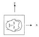
- FIG. 1schematically illustrates a front view of an electronic device in the form of a mobile phone, where the front side includes a display and a camera;
- FIG. 2illustrates a side view of the device of FIG. 1 ;
- FIG. 3schematically illustrates a rear view of the device of FIGS. 1 and 2 , where the rear side may include a further camera;
- FIG. 4schematically illustrates a scenario where a user interacts with and operates an electronic device of FIGS. 1-3 by holding the device rotated approximately 90° from the orientation depicted in FIG. 1 ;
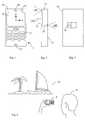
- FIG. 5schematically illustrates an image of the user of the device, captured by the camera shown in FIG. 1 ;
- FIG. 6schematically illustrates how selected features of the image of the user, such as the eyes and mouth, are identified by an image identifying function in the electronic device;
- FIG. 7illustrates how the identified features are associated with a normal vertical axis and horizontal axis of a face of a human user
- FIG. 8schematically illustrates how the relative rotational orientation of the image is determined, compared to the orientation of the electronic device
- FIG. 9schematically illustrates how an operator function is applied to the data representation displayed on the display of the electronic device, which operator function is dependent on the determined rotational orientation
- FIG. 10schematically illustrates how the data representation displayed on the display has been adjusted by rotation
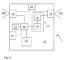
- FIG. 11schematically illustrates a block diagram of functional features of an electronic device in accordance with an embodiment of the invention.
- the present descriptionrelates to the field of electronic devices including a digital camera.
- a preferred embodiment of the inventionrelates to a portable communication device configured for video telephony, such as a 3G mobile phone.
- the inventionis particularly suitable for mobile phones, but is as such equally applicable to digital devices which do not include radio communication capabilities.
- most embodiments outlined hereinare related to mobile phones. Preferred embodiments will now be described with reference to the accompanying drawings.
- a portable communication device 1configured in accordance with an embodiment of the invention is shown from three different angles in FIGS. 1-3 , and in the form of a block diagram in FIG. 11 .
- the portable radio communication device 1may e.g. be a mobile telephone as depicted in the figures.
- the portable radio communication device 1comprises a support structure 10 including a housing and a chassis, arranged to support other elements of the device.
- a user interfaceincludes a keypad or keyboard 11 and a display 12 .
- the device 1also includes an audio interface including a microphone 13 and a speaker 14 , as well as radio transceiver circuitry and antenna 23 , even though these elements are not of importance for the invention and can be dispensed with if the invention is employed in another electronic device, e.g.
- the device 1as a communication device is known to persons skilled in the art, and will therefore not be described in any greater detail herein. It should also be noted that the list of features and elements included in the device 1 is in no way exhaustive. On the contrary, while the device 1 shown and described represents only one possible embodiment, it may well comprise further features and elements providing other functions.
- the device 1also includes a camera 15 , which may be positioned adjacent to display 12 as depicted in FIG. 1 , and aimed such that its field of view (FOV) 150 is likely to cover a user watching display 12 . Consequently, the camera 15 is aimed in a direction substantially common with a normal viewing direction of the display 12 .
- the device 1may additionally include a further camera 16 . This further camera 16 is of little I 5 importance for the invention and can, hence, be dispensed with in some embodiments of the invention. From the discussion hereinbelow, it will be clear to the reader that the camera 15 , which is positioned adjacent to display 12 in FIG.
- the device 1is sufficient for the purpose of orientation adjustment in accordance with the embodiments of the present invention.
- this camera 16should preferably be aimed such that its FOV 160 does not overlap the FOV 150 of the camera 15 .
- the two cameras 15 and 16are aimed at substantially opposite directions, but they may optionally be directed approximately 90° to each other. It is in fact not essential that the two cameras 15 and 16 have fixed line of sights, the further camera 16 could indeed e.g. be rotatable in a socket in support structure 10 to some extent.
- FIG. 1a vertical axis y and a horizontal axis x are defined for the device 1 . More specifically, the y axis represents the longitudinal direction of the device 1 . If a user interacts with and operates with the device 1 when the device 1 is held as shown in FIG. 1 , i.e. with the y axis held vertically, a data representation on the display device 12 is generally displayed in a portrait orientation.
- FIG. 4illustrates a different scenario, where a user 41 interacts with and operates the device 1 in another orientation. In this position, the device 1 has been rotated approximately 90° counter clockwise, such that horizontal axis x of device 1 now points vertically upwards.
- a prior art devicewould as a default rule not compensate for this approximately 90° counter clockwise rotation of the device 1 when presenting the data representation on the display 12 .
- a prior art devicewould as a default rule present the data representation on the display 12 in exactly the same rotation as it does when the device 1 is held as shown in FIG. 1 , i.e. in the portrait orientation.
- it would be more appropriate for the userif the data were displayed in a landscape orientation when the device 1 has the orientation as depicted in FIG. 4 .
- a target of the present inventionis to facilitate presentation of a data representation on display 12 (or another display), such that the displayed data representation on the display 12 is presented on the display 12 in the most appropriate rotation orientation in dependence of the orientation of the device 1 .
- the camera 15is used to determine the orientation of the device 1 when capturing images. This is particularly useful in mobile phones 1 that support video telephony, where a video telephony camera (VTC) 15 is included.
- the VTC 15is normally directed towards the face of the user 41 and is configured to capture images either continuously, or as an alternative only upon activation of an image recording trigger.
- the present orientation of device 1is then determined by analyzing the image captured by the camera 15 , and the determined orientation is subsequently used to manipulate a displayed data representation on the display device 12 , so as to rotate the data representation to either a landscape or a portrait orientation in dependence of the determined orientation of device 1 .
- the device 1is arranged to present a data representation on the display 12 in a portrait orientation, when the device 1 has the position as depicted in FIG. 1 . Further, the device 1 is arranged to present a data representation on the display 12 in a landscape orientation when the device 1 has the position as depicted in FIG. 4 .
- the present orientation of device 1is determined by identifying at least two features in the image captured by the camera 15 .
- three features in the face of the user 41are identified. These features preferably include the eyes and mouth of the user. Alternatively, though, other features may be identified if they are better suited for the purpose, such as the chin, the nose, the ears, or the hairline.
- Three featuresare preferably identified in the image, in order to determine in which direction the device 1 is rotated. With only two features, it may become too difficult to discriminate between clockwise and counter-clockwise rotation. Numerous software-based processes for facial feature identification and recognition purposes have been presented in papers and in real products, and several patents have been granted within this field. As a mere example, A. W.
- U.S. Pat. No. 5,933,527 to Ishikawadiscloses a facial image processing method and apparatus, by means of which areas of facial features may be extracted, and coordinate data related to those areas can be extracted.
- an image of the user 41can be captured by means of the camera 15 , this image being shown in FIG. 5 .
- This imageis preferably captured continuously by the camera 15 .
- An image recording trigger 22typically a push-button or the like, is therefore operatively connected to the camera 15 , wherein activation of the trigger causes the camera 15 to record images within its FOV 150 .
- the image of FIG. 5is passed from camera 15 to an orientation detector 17 .
- the orientation detector 17is preferably realized by means of software executed by a processor device, but is indicated in FIG.
- Orientation detector 17comprises an image feature detector 18 , operable to analyze the image received to identify images features in an image captured by the camera 15 . This is illustrated in FIG. 6 , where two eye portions and a mouth portion of the image have been detected and identified as eyes and mouth of the user.
- the image areas 181 representing the positions of the eyes, and 182 representing the position of the mouthhave been extracted from the captured image of the user. This does not mean that an image as shown in FIG. 7 must be generated, but that these are now the areas of interest in the captured image.
- Orientation detector 17is preferably configured to detect facial image features, and is thereby configured to determine that a line passing through the eye portions 181 defines a baseline, whereas the position of mouth portion 182 relative to that baseline represents the lower part of the image.
- a coordinate system for the captured imagemay be defined, where a horizontal image axis x′ is parallel to the baseline, and a vertical image axis y′ is orthogonal to the baseline, with the positive direction of the y′ axis extending away from the position of the mouth area portion 182 , as counted from the baseline.
- the orientation of the image captured by camera 15 , in the image plane,is thereby determined in accordance with FIG. 7 .
- the rotation orientation of the imageis then determined relative to a pre-stored reference orientation.
- the reference positionis preferably a vertical orientation of the face, which in FIG. 8 is represented by a vertical axis y and a horizontal axis x, corresponding to the vertical and horizontal axes of the device 1 as such.
- Calculator unit 19is configured to calculate the rotational difference between the coordinate system of axis x′, y′ and the coordinate system of axis x, y, to determine a rotation angle ⁇ .
- the calculator unit 19is configured to disregard deviations from a perfectly vertical or horizontal orientation of the device 1 . In fact, any inclination from these two orthogonal orientations may indeed be up to the artistic freedom of the user. Furthermore, it cannot be guaranteed that the user holds his or her head in a perfectly upright position. For these reasons, calculator unit 19 is preferably configured to output only rotation angles ⁇ in steps of 90°, in order to produce an angle ⁇ usable for transforming a data representation displayed on the display 12 between landscape and portrait orientations, and to make distinction between up and down.
- the orientation detectoris thereby configured to detect the orientation of a captured image relative to a vertical orientation and a horizontal orientation, and to determine that the support structure of the device 1 is either vertically oriented or horizontally orientated dependent on which of these orientations matches closest with the captured image of the camera 15 .
- the output value of ⁇is 0 (zero).
- Orientation detector 17outputs the output value of angle ⁇ to microprocessor 20 .
- microprocessor 20thereby processes the data representation 90 (which in this illustrative example includes text as well as a visual image) displayed on the display 12 using an operator function f( ⁇ ), which logistically involves the operation of rotating the data representation 90 presented on the display device 12 by the received angle ⁇ .
- FIG. 10illustrates the result from which it is evident that the data representation 90 has been rotated by approximately 90°, as detected by orientation detector 17 .
- Information of the angle ⁇may be stored in a memory 21 in the device 1 .
- the memory 21does not have to be permanently attached to the device 1 , it may e.g. just as well be arranged on an insertable IC memory card. Storing previously calculated rotation angles inter alia has the advantage that if the device 1 , for any reason, would fail to perform a valid face recognition later, it is possible to use the last known rotation angle.
- the embodiment of the process for image rotation orientation adjustment described in conjunction with FIG. 4utilizes of facial feature identification and recognition for determining the rotational orientation of device 1 .
- human silhouette recognitionthe silhouette of a human user (as opposed to facial features of the human user) is identified and recognized.
- the silhouette of the human usermay include the silhouette of face of the human user.
- Processes for human silhouette identification and recognition purposeshave been presented in papers. As a mere example, Rocio Diaz de Leon, Luis Enrique Sucar, “Human Silhouette Recognition with Fourier Descriptors,” icpr, p.
- Optical Character Recognitioncould be used.
- OCROptical Character Recognition
- the embodiment of the process for image rotation orientation adjustment described in conjunction with FIG. 4utilizes of facial feature identification and recognition for determining the rotational orientation of device 1 .
- OCROptical Character Recognition
- the presented solutionis different from existing solutions inter alia in that it assumes the use of a camera as the orientation sensing device.
- a device 1 according to the present inventionis therefore particularly suitable if the device 1 already includes a camera 15 for any other purpose anyway.
- a best mode of the invention known to dateis therefore to employ the invention in a mobile phone equipped with a camera 15 for video telephony purposes.
- the advantage offered by the invention when applied in such a mobile phone 1is that it makes use of existing components to provide added value to the customer.
- the device 1may be combined with a solution for adjusting image rotation orientation of images captured by the further camera 16 , such that images captured by the further camera 16 may be stored in a common orientation regardless of how the device 1 is oriented when the image was captured by the further camera 16 .
- a solutionis disclosed in U.S. application Ser. No. 11/425,395 filed on Jun. 21, 2006.
- the device 1would, hence, comprise, a support structure; a camera 15 carried by the support structure; a further camera 16 carried by the support structure; an orientation detector connected to the camera 15 , configured to identify images features in an image captured by the camera 15 , and to determine rotation orientation of the image relative to a reference orientation; and a data storing device configured to store image data of images captured by the further camera 16 in an orientation dependent on determined rotation orientation.
- the data storing devicemay be configured to store image data in the orientation as captured by the further camera 16 , or rotated in one more steps of 90° as determined by the orientation detector.
Landscapes
- Engineering & Computer Science (AREA)
- Physics & Mathematics (AREA)
- Multimedia (AREA)
- General Physics & Mathematics (AREA)
- Theoretical Computer Science (AREA)
- Oral & Maxillofacial Surgery (AREA)
- Signal Processing (AREA)
- Health & Medical Sciences (AREA)
- Geometry (AREA)
- Computer Hardware Design (AREA)
- General Health & Medical Sciences (AREA)
- Human Computer Interaction (AREA)
- Studio Devices (AREA)
- Telephone Function (AREA)
- Image Processing (AREA)
- Position Input By Displaying (AREA)
Abstract
Description
- detecting the orientation of an image captured by the camera relative to a vertical orientation and a horizontal orientation;
- determining that the support structure is either vertically oriented or horizontally orientated dependent on which of these orientations matches closest with the captured image of the camera.
- If 45°<θ<135°, then the output value of θ is set to 90°.
- If 135°<θ<225°, then the output value of θ is set to 180°.
- If 225°<θ<315°, then the output value of θ is set to 270°, i.e. −90°.
Claims (28)
Priority Applications (6)
| Application Number | Priority Date | Filing Date | Title |
|---|---|---|---|
| US11/692,443US8244068B2 (en) | 2007-03-28 | 2007-03-28 | Device and method for adjusting orientation of a data representation displayed on a display |
| PCT/EP2007/058865WO2008116503A1 (en) | 2007-03-28 | 2007-08-27 | Device and method for adjusting orientation of a data representation displayed on a display |
| KR1020097022440AKR20090125207A (en) | 2007-03-28 | 2007-08-27 | Apparatus and method for adjusting the orientation of data representations displayed on a display |
| CN2007800524185ACN101641950B (en) | 2007-03-28 | 2007-08-27 | Apparatus and method for adjusting the orientation of a data representation displayed on a display |
| EP07802905AEP2130368A1 (en) | 2007-03-28 | 2007-08-27 | Device and method for adjusting orientation of a data representation displayed on a display |
| JP2010500083AJP2010525425A (en) | 2007-03-28 | 2007-08-27 | Apparatus and method for adjusting the direction of data representation displayed on a display device |
Applications Claiming Priority (1)
| Application Number | Priority Date | Filing Date | Title |
|---|---|---|---|
| US11/692,443US8244068B2 (en) | 2007-03-28 | 2007-03-28 | Device and method for adjusting orientation of a data representation displayed on a display |
Publications (2)
| Publication Number | Publication Date |
|---|---|
| US20080239131A1 US20080239131A1 (en) | 2008-10-02 |
| US8244068B2true US8244068B2 (en) | 2012-08-14 |
Family
ID=38754540
Family Applications (1)
| Application Number | Title | Priority Date | Filing Date |
|---|---|---|---|
| US11/692,443Expired - Fee RelatedUS8244068B2 (en) | 2007-03-28 | 2007-03-28 | Device and method for adjusting orientation of a data representation displayed on a display |
Country Status (6)
| Country | Link |
|---|---|
| US (1) | US8244068B2 (en) |
| EP (1) | EP2130368A1 (en) |
| JP (1) | JP2010525425A (en) |
| KR (1) | KR20090125207A (en) |
| CN (1) | CN101641950B (en) |
| WO (1) | WO2008116503A1 (en) |
Cited By (11)
| Publication number | Priority date | Publication date | Assignee | Title |
|---|---|---|---|---|
| US20110222676A1 (en)* | 2008-11-20 | 2011-09-15 | Panasonic Corporation | Image display apparatus, teleconferencing device, and image display method |
| US8965451B2 (en) | 2012-03-22 | 2015-02-24 | Kabushiki Kaisha Toshiba | Information processing terminal device |
| US9239617B2 (en) | 2012-05-02 | 2016-01-19 | Samsung Electronics Co., Ltd | Apparatus and method of controlling mobile terminal based on analysis of user's face |
| US20170153715A1 (en)* | 2005-04-06 | 2017-06-01 | Sony Corporation | Reproducing device, setting changing method, and setting changing device |
| US9907457B2 (en) | 2013-02-01 | 2018-03-06 | Deka Products Limited Partnership | Endoscope with pannable camera |
| US10003918B1 (en) | 2016-04-06 | 2018-06-19 | Worldwide Live Holding, Llc | Location based local emergency contact |
| US10616491B2 (en) | 2013-02-01 | 2020-04-07 | Deka Products Limited Partnership | Endoscope with pannable camera and related method |
| US10932103B1 (en)* | 2014-03-21 | 2021-02-23 | Amazon Technologies, Inc. | Determining position of a user relative to a tote |
| US11947741B2 (en) | 2021-10-03 | 2024-04-02 | David Ungarish | Controlling viewing orientation of a mobile device display |
| US11986162B2 (en) | 2018-04-26 | 2024-05-21 | Deka Products Limited Partnership | Endoscope with rotatable camera and related methods |
| US20250147580A1 (en)* | 2023-11-02 | 2025-05-08 | Acer Incorporated | Display apparatus |
Families Citing this family (36)
| Publication number | Priority date | Publication date | Assignee | Title |
|---|---|---|---|---|
| US20110298829A1 (en)* | 2010-06-04 | 2011-12-08 | Sony Computer Entertainment Inc. | Selecting View Orientation in Portable Device via Image Analysis |
| US7724296B2 (en)* | 2006-06-21 | 2010-05-25 | Sony Ericsson Mobile Communications Ab | Device and method for adjusting image orientation |
| US20080266326A1 (en)* | 2007-04-25 | 2008-10-30 | Ati Technologies Ulc | Automatic image reorientation |
| KR20090101733A (en)* | 2008-03-24 | 2009-09-29 | 삼성전자주식회사 | Mobile terminal and displaying method of display information using face recognition thereof |
| WO2010030984A1 (en)* | 2008-09-12 | 2010-03-18 | Gesturetek, Inc. | Orienting a displayed element relative to a user |
| CN102203850A (en)* | 2008-09-12 | 2011-09-28 | 格斯图尔泰克公司 | Orients displayed elements relative to the user |
| CN101877736A (en)* | 2009-04-30 | 2010-11-03 | 深圳富泰宏精密工业有限公司 | Automatic adjusting system and method for user interface of mobile terminal |
| JP2011015304A (en)* | 2009-07-03 | 2011-01-20 | Sanyo Electric Co Ltd | Electronic camera |
| US20110002487A1 (en)* | 2009-07-06 | 2011-01-06 | Apple Inc. | Audio Channel Assignment for Audio Output in a Movable Device |
| US9305232B2 (en)* | 2009-07-22 | 2016-04-05 | Blackberry Limited | Display orientation change for wireless devices |
| JP2011055476A (en)* | 2009-08-06 | 2011-03-17 | Canon Inc | Display apparatus |
| TW201112045A (en)* | 2009-09-28 | 2011-04-01 | Wistron Corp | Viewing direction determination method, viewing direction determination apparatus, image processing method, image processing apparatus and display device |
| WO2012030265A1 (en) | 2010-08-30 | 2012-03-08 | Telefonaktiebolaget L M Ericsson (Publ) | Face screen orientation and related devices and methods |
| WO2012030267A1 (en) | 2010-08-30 | 2012-03-08 | Telefonaktiebolaget L M Ericsson (Publ) | Methods of launching applications responsive to device orientation and related electronic devices |
| US8593558B2 (en)* | 2010-09-08 | 2013-11-26 | Apple Inc. | Camera-based orientation fix from portrait to landscape |
| JPWO2012108273A1 (en)* | 2011-02-09 | 2014-07-03 | Necカシオモバイルコミュニケーションズ株式会社 | Image display device, image display method, and program |
| US8553129B2 (en)* | 2011-05-10 | 2013-10-08 | Htc Corporation | Handheld electronic device with two lens modules, dual image capturing method applying for the handheld electronic device, and computer program product for load into the handheld electronic device |
| KR101818573B1 (en) | 2011-07-07 | 2018-01-15 | 삼성전자 주식회사 | Method and apparatus for displaying of view mode using face recognition |
| DE102012110278B8 (en)* | 2011-11-02 | 2025-07-17 | Beijing Lenovo Software Ltd. | Methods and devices for window display and methods and devices for touch operation of applications |
| JP6146307B2 (en)* | 2011-11-10 | 2017-06-14 | 株式会社ニコン | Electronic device, information system, server, and program |
| US8971574B2 (en)* | 2011-11-22 | 2015-03-03 | Ulsee Inc. | Orientation correction method for electronic device used to perform facial recognition and electronic device thereof |
| US9449583B2 (en)* | 2011-12-15 | 2016-09-20 | Lenovo (Beijing) Co., Ltd. | Control method and electronic apparatus |
| KR101969931B1 (en) | 2012-01-10 | 2019-04-17 | 삼성전자주식회사 | Apparatus and method for controlling rotation of display image |
| KR101992397B1 (en)* | 2012-06-27 | 2019-09-27 | 삼성전자주식회사 | Image process apparatus, image relay apparatus, method for image process, and method for image relay thereof |
| EP2743797A1 (en) | 2012-12-13 | 2014-06-18 | Tobii Technology AB | Rotation of visual content on a display unit |
| CN103117053B (en)* | 2012-12-27 | 2015-03-04 | 苏州佳世达电通有限公司 | Picture rotating method of electronic device |
| WO2014113951A1 (en) | 2013-01-24 | 2014-07-31 | 华为终端有限公司 | Method for determining screen display mode and terminal device |
| CN103152522A (en)* | 2013-02-25 | 2013-06-12 | 东莞宇龙通信科技有限公司 | Method and Terminal for Adjusting Shooting Position |
| CN104598030B (en)* | 2015-01-15 | 2018-03-23 | 青岛海信电器股份有限公司 | A kind of intelligent terminal operating key function automatic adjusting method, device and intelligent terminal |
| JP2017151493A (en)* | 2016-02-22 | 2017-08-31 | 富士ゼロックス株式会社 | Image processing device, image reading device, and program |
| US10877010B2 (en)* | 2016-03-31 | 2020-12-29 | Honeywell International Inc. | Clydesdale gas detector with improved screen orientation based on input from attachment sensor |
| CN106125933A (en)* | 2016-06-28 | 2016-11-16 | 维沃移动通信有限公司 | The method of a kind of display interface rotation and mobile terminal |
| US10347218B2 (en)* | 2016-07-12 | 2019-07-09 | Qualcomm Incorporated | Multiple orientation detection |
| US20190026120A1 (en)* | 2017-07-21 | 2019-01-24 | International Business Machines Corporation | Customizing mobile device operation based on touch points |
| CN108234891B (en)* | 2018-04-04 | 2019-11-05 | 维沃移动通信有限公司 | A kind of photographic method and mobile terminal |
| US11792506B2 (en)* | 2022-02-09 | 2023-10-17 | Motorola Mobility Llc | Electronic devices and corresponding methods for defining an image orientation of captured images |
Citations (16)
| Publication number | Priority date | Publication date | Assignee | Title |
|---|---|---|---|---|
| EP0884905A2 (en) | 1997-06-13 | 1998-12-16 | Nokia Mobile Phones Ltd. | A method for producing an image to be transmitted from a terminal and the terminal |
| US5900909A (en) | 1995-04-13 | 1999-05-04 | Eastman Kodak Company | Electronic still camera having automatic orientation sensing and image correction |
| US5933527A (en) | 1995-06-22 | 1999-08-03 | Seiko Epson Corporation | Facial image processing method and apparatus |
| WO2001031893A1 (en) | 1999-10-26 | 2001-05-03 | Nokia Corporation | Mobile phone |
| WO2002037179A2 (en) | 2000-11-01 | 2002-05-10 | Koninklijke Philips Electronics N.V. | Method and apparatus for tracking an object using a camera in a hand-held processing device |
| US20030016883A1 (en) | 2001-07-20 | 2003-01-23 | Baron John M. | System and method for horizon correction within images |
| US20040017506A1 (en) | 2002-07-26 | 2004-01-29 | Livingston Kris R. | Camera having camera orientation sensing capability |
| US20040076341A1 (en)* | 2001-03-30 | 2004-04-22 | Sharp Laboratories Of America, Inc. | System and method for digital document alignment |
| US20050044510A1 (en)* | 2003-08-11 | 2005-02-24 | Samsung Electronics Co., Ltd. | Display device for a portable terminal capable of displaying an adaptive image |
| JP2005100084A (en) | 2003-09-25 | 2005-04-14 | Toshiba Corp | Image processing apparatus and method |
| FR2861524A1 (en) | 2003-10-23 | 2005-04-29 | Thomson Licensing Sa | Method for detecting orientation of image taken by digital camera, involves detecting lines in image, calculating attributes that characterize lines, for each detected line, and detecting orientation of image according to attributes |
| JP2005202477A (en) | 2004-01-13 | 2005-07-28 | Fuji Photo Film Co Ltd | Method for deciding top-and-bottom direction of face image and image recording device and image reproducing device |
| JP2005266061A (en) | 2004-03-17 | 2005-09-29 | Olympus Corp | Reproduction apparatus |
| US20060222264A1 (en)* | 2005-03-31 | 2006-10-05 | Siemens Ag | Method for vertically orienting a face shown in a picture |
| US20060227103A1 (en)* | 2005-04-08 | 2006-10-12 | Samsung Electronics Co., Ltd. | Three-dimensional display device and method using hybrid position-tracking system |
| US20070296820A1 (en)* | 2006-06-21 | 2007-12-27 | Sony Ericsson Mobile Communications Ab | Device and method for adjusting image orientation |
Family Cites Families (6)
| Publication number | Priority date | Publication date | Assignee | Title |
|---|---|---|---|---|
| JP2000076380A (en)* | 1998-08-31 | 2000-03-14 | Casio Comput Co Ltd | Handwritten character input device and storage medium |
| JP2004046399A (en)* | 2002-07-10 | 2004-02-12 | Mitsubishi Heavy Ind Ltd | Face recognition device and method |
| WO2004077820A1 (en)* | 2003-02-25 | 2004-09-10 | Matsushita Electric Industrial Co. Ltd. | Image pickup processing method and image pickup apparatus |
| US7565030B2 (en)* | 2003-06-26 | 2009-07-21 | Fotonation Vision Limited | Detecting orientation of digital images using face detection information |
| JP2006040050A (en)* | 2004-07-28 | 2006-02-09 | Olympus Corp | Reproduction device, camera and display switching method for reproduction device |
| JP2006053666A (en)* | 2004-08-10 | 2006-02-23 | Olympus Corp | Image processing program, image processing method, image processing apparatus, and recording medium |
- 2007
- 2007-03-28USUS11/692,443patent/US8244068B2/ennot_activeExpired - Fee Related
- 2007-08-27CNCN2007800524185Apatent/CN101641950B/enactiveActive
- 2007-08-27JPJP2010500083Apatent/JP2010525425A/enactivePending
- 2007-08-27EPEP07802905Apatent/EP2130368A1/ennot_activeWithdrawn
- 2007-08-27KRKR1020097022440Apatent/KR20090125207A/ennot_activeCeased
- 2007-08-27WOPCT/EP2007/058865patent/WO2008116503A1/enactiveApplication Filing
Patent Citations (19)
| Publication number | Priority date | Publication date | Assignee | Title |
|---|---|---|---|---|
| US5900909A (en) | 1995-04-13 | 1999-05-04 | Eastman Kodak Company | Electronic still camera having automatic orientation sensing and image correction |
| US5933527A (en) | 1995-06-22 | 1999-08-03 | Seiko Epson Corporation | Facial image processing method and apparatus |
| EP0884905A3 (en) | 1997-06-13 | 2000-01-19 | Nokia Mobile Phones Ltd. | A method for producing an image to be transmitted from a terminal and the terminal |
| EP0884905A2 (en) | 1997-06-13 | 1998-12-16 | Nokia Mobile Phones Ltd. | A method for producing an image to be transmitted from a terminal and the terminal |
| WO2001031893A1 (en) | 1999-10-26 | 2001-05-03 | Nokia Corporation | Mobile phone |
| WO2002037179A2 (en) | 2000-11-01 | 2002-05-10 | Koninklijke Philips Electronics N.V. | Method and apparatus for tracking an object using a camera in a hand-held processing device |
| WO2002037179A3 (en) | 2000-11-01 | 2002-09-06 | Koninkl Philips Electronics Nv | Method and apparatus for tracking an object using a camera in a hand-held processing device |
| US20040076341A1 (en)* | 2001-03-30 | 2004-04-22 | Sharp Laboratories Of America, Inc. | System and method for digital document alignment |
| US20030016883A1 (en) | 2001-07-20 | 2003-01-23 | Baron John M. | System and method for horizon correction within images |
| US20040017506A1 (en) | 2002-07-26 | 2004-01-29 | Livingston Kris R. | Camera having camera orientation sensing capability |
| US20050044510A1 (en)* | 2003-08-11 | 2005-02-24 | Samsung Electronics Co., Ltd. | Display device for a portable terminal capable of displaying an adaptive image |
| JP2005100084A (en) | 2003-09-25 | 2005-04-14 | Toshiba Corp | Image processing apparatus and method |
| US20050104848A1 (en)* | 2003-09-25 | 2005-05-19 | Kabushiki Kaisha Toshiba | Image processing device and method |
| FR2861524A1 (en) | 2003-10-23 | 2005-04-29 | Thomson Licensing Sa | Method for detecting orientation of image taken by digital camera, involves detecting lines in image, calculating attributes that characterize lines, for each detected line, and detecting orientation of image according to attributes |
| JP2005202477A (en) | 2004-01-13 | 2005-07-28 | Fuji Photo Film Co Ltd | Method for deciding top-and-bottom direction of face image and image recording device and image reproducing device |
| JP2005266061A (en) | 2004-03-17 | 2005-09-29 | Olympus Corp | Reproduction apparatus |
| US20060222264A1 (en)* | 2005-03-31 | 2006-10-05 | Siemens Ag | Method for vertically orienting a face shown in a picture |
| US20060227103A1 (en)* | 2005-04-08 | 2006-10-12 | Samsung Electronics Co., Ltd. | Three-dimensional display device and method using hybrid position-tracking system |
| US20070296820A1 (en)* | 2006-06-21 | 2007-12-27 | Sony Ericsson Mobile Communications Ab | Device and method for adjusting image orientation |
Non-Patent Citations (6)
| Title |
|---|
| A.W. "Face and Feature Finding for a Face Recognition System" In proceedings of Audio- and Video based Biometric Person Authentication '99 pp. 154-159, Washington D.C. USA, Mar. 22-24, 1999. |
| International Search Report corresponding to PCT/EP2007/058865, mailed Dec. 19, 2007. |
| Office Action for corresponding Japanese Application No. 2010-500083 dated Feb. 3, 2012. |
| Pending U.S. Appl. No. 11/425,395, filed Jun. 21, 2006, application attached. |
| Rocio Diaz de Leon, Luis Enrique Sucar, "Human Silhouette Recognition with Fourier Descriptors," icpr. p. 3713, 15th International Conference on Pattern Recognition (ICPR '00)-vol. 3, 2000. |
| Written Opinion corresponding to PCT/EP2007/058865, mailed Dec. 19, 2007. |
Cited By (21)
| Publication number | Priority date | Publication date | Assignee | Title |
|---|---|---|---|---|
| US20170153715A1 (en)* | 2005-04-06 | 2017-06-01 | Sony Corporation | Reproducing device, setting changing method, and setting changing device |
| US10242429B2 (en)* | 2005-04-06 | 2019-03-26 | Sony Corporation | Reproducing device, setting changing method, and setting changing device |
| US20110222676A1 (en)* | 2008-11-20 | 2011-09-15 | Panasonic Corporation | Image display apparatus, teleconferencing device, and image display method |
| US8965451B2 (en) | 2012-03-22 | 2015-02-24 | Kabushiki Kaisha Toshiba | Information processing terminal device |
| US10114458B2 (en) | 2012-05-02 | 2018-10-30 | Samsung Electronics Co., Ltd | Apparatus and method of controlling mobile terminal based on analysis of user's face |
| US9459826B2 (en) | 2012-05-02 | 2016-10-04 | Samsung Electronics Co., Ltd | Apparatus and method of controlling mobile terminal based on analysis of user's face |
| US9239617B2 (en) | 2012-05-02 | 2016-01-19 | Samsung Electronics Co., Ltd | Apparatus and method of controlling mobile terminal based on analysis of user's face |
| US9907457B2 (en) | 2013-02-01 | 2018-03-06 | Deka Products Limited Partnership | Endoscope with pannable camera |
| US12200363B2 (en) | 2013-02-01 | 2025-01-14 | Deka Products Limited Partnership | Endoscope with pannable camera and related method |
| US12075975B2 (en) | 2013-02-01 | 2024-09-03 | Deka Products Limited Partnership | Endoscope with pannable camera |
| US10616491B2 (en) | 2013-02-01 | 2020-04-07 | Deka Products Limited Partnership | Endoscope with pannable camera and related method |
| US10863888B2 (en) | 2013-02-01 | 2020-12-15 | Deka Products Limited Partnership | Endoscope with pannable camera |
| US10362927B2 (en) | 2013-02-01 | 2019-07-30 | Deka Products Limited Partnership | Endoscope with pannable camera |
| US10932103B1 (en)* | 2014-03-21 | 2021-02-23 | Amazon Technologies, Inc. | Determining position of a user relative to a tote |
| US10178304B1 (en) | 2016-04-06 | 2019-01-08 | Worldwide Live Holding, Llc | Ensuring that video or images are captured at a determined orientation |
| US10070051B1 (en) | 2016-04-06 | 2018-09-04 | Worldwide Live Holding, Llc | Methods for ensuring that video or images are captured at a determined orientation |
| US10051416B1 (en) | 2016-04-06 | 2018-08-14 | Worldwide Live Holding, Llc | Methods for selective geo-darkening |
| US10003918B1 (en) | 2016-04-06 | 2018-06-19 | Worldwide Live Holding, Llc | Location based local emergency contact |
| US11986162B2 (en) | 2018-04-26 | 2024-05-21 | Deka Products Limited Partnership | Endoscope with rotatable camera and related methods |
| US11947741B2 (en) | 2021-10-03 | 2024-04-02 | David Ungarish | Controlling viewing orientation of a mobile device display |
| US20250147580A1 (en)* | 2023-11-02 | 2025-05-08 | Acer Incorporated | Display apparatus |
Also Published As
| Publication number | Publication date |
|---|---|
| JP2010525425A (en) | 2010-07-22 |
| CN101641950A (en) | 2010-02-03 |
| EP2130368A1 (en) | 2009-12-09 |
| CN101641950B (en) | 2013-09-04 |
| US20080239131A1 (en) | 2008-10-02 |
| WO2008116503A1 (en) | 2008-10-02 |
| KR20090125207A (en) | 2009-12-03 |
Similar Documents
| Publication | Publication Date | Title |
|---|---|---|
| US8244068B2 (en) | Device and method for adjusting orientation of a data representation displayed on a display | |
| US7724296B2 (en) | Device and method for adjusting image orientation | |
| Xu et al. | Seeing double: Reconstructing obscured typed input from repeated compromising reflections | |
| US8379059B2 (en) | Portable electronic device and method for adjusting display orientation of the portable electronic device | |
| US8896533B2 (en) | Display directional sensing | |
| US7706579B2 (en) | Image orientation for display | |
| CN110572711B (en) | Video cover generation method and device, computer equipment and storage medium | |
| TW201214299A (en) | Selecting view orientation in portable device via image analysis | |
| KR20110133698A (en) | Method and device for operating camera function in portable terminal | |
| KR20150039355A (en) | Mobile terminal and control method thereof | |
| CN112445342B (en) | Display control method, device and electronic equipment | |
| CN113643024B (en) | Graphic code processing method and device and electronic equipment | |
| KR20150003501A (en) | Electronic device and method for authentication using fingerprint information | |
| KR20150073174A (en) | Image capturing device and method thereof | |
| CN112883832A (en) | Method and device for managing behavior of person under test, electronic equipment and storage medium | |
| JP6201282B2 (en) | Portable electronic device, its control method and program | |
| US12277804B2 (en) | Spoof detection using catadioptric spatiotemporal corneal reflection dynamics | |
| CN111586279A (en) | Method, device and equipment for determining shooting state and storage medium | |
| CN114140839A (en) | Image sending method, device and equipment for face recognition and storage medium | |
| CN112052708B (en) | Article detection method, device and system | |
| JP2014220555A (en) | Imaging apparatus, control method of the same, and program | |
| US9824475B2 (en) | Obscuring displayed information | |
| CN218299213U (en) | Learning machine | |
| US11961315B1 (en) | Methods and systems for enhancing detection of a fraudulent identity document in an image | |
| US20230142200A1 (en) | Non-transitory storage medium, processing method for portable terminal, and portable terminal |
Legal Events
| Date | Code | Title | Description |
|---|---|---|---|
| AS | Assignment | Owner name:SONY ERICSSON MOBILE COMMUNICATIONS AB, SWEDEN Free format text:ASSIGNMENT OF ASSIGNORS INTEREST;ASSIGNOR:THORN, OLA;REEL/FRAME:019185/0879 Effective date:20070417 | |
| ZAAA | Notice of allowance and fees due | Free format text:ORIGINAL CODE: NOA | |
| ZAAB | Notice of allowance mailed | Free format text:ORIGINAL CODE: MN/=. | |
| STCF | Information on status: patent grant | Free format text:PATENTED CASE | |
| FPAY | Fee payment | Year of fee payment:4 | |
| AS | Assignment | Owner name:SONY MOBILE COMMUNICATIONS AB, SWEDEN Free format text:CHANGE OF NAME;ASSIGNOR:SONY ERICSSON MOBILE COMMUNICATIONS AB;REEL/FRAME:048690/0974 Effective date:20120221 | |
| AS | Assignment | Owner name:SONY CORPORATION, JAPAN Free format text:ASSIGNMENT OF ASSIGNORS INTEREST;ASSIGNOR:SONY MOBILE COMMUNICATIONS AB;REEL/FRAME:048825/0737 Effective date:20190405 | |
| MAFP | Maintenance fee payment | Free format text:PAYMENT OF MAINTENANCE FEE, 8TH YEAR, LARGE ENTITY (ORIGINAL EVENT CODE: M1552); ENTITY STATUS OF PATENT OWNER: LARGE ENTITY Year of fee payment:8 | |
| FEPP | Fee payment procedure | Free format text:MAINTENANCE FEE REMINDER MAILED (ORIGINAL EVENT CODE: REM.); ENTITY STATUS OF PATENT OWNER: LARGE ENTITY | |
| LAPS | Lapse for failure to pay maintenance fees | Free format text:PATENT EXPIRED FOR FAILURE TO PAY MAINTENANCE FEES (ORIGINAL EVENT CODE: EXP.); ENTITY STATUS OF PATENT OWNER: LARGE ENTITY | |
| STCH | Information on status: patent discontinuation | Free format text:PATENT EXPIRED DUE TO NONPAYMENT OF MAINTENANCE FEES UNDER 37 CFR 1.362 | |
| FP | Lapsed due to failure to pay maintenance fee | Effective date:20240814 |