US8243583B2 - OFDM/DMT/digital communications system including partial sequence symbol processing - Google Patents
OFDM/DMT/digital communications system including partial sequence symbol processingDownload PDFInfo
- Publication number
- US8243583B2 US8243583B2US13/012,683US201113012683AUS8243583B2US 8243583 B2US8243583 B2US 8243583B2US 201113012683 AUS201113012683 AUS 201113012683AUS 8243583 B2US8243583 B2US 8243583B2
- Authority
- US
- United States
- Prior art keywords
- sequence
- signals
- subsets
- digital data
- symbols
- Prior art date
- Legal status (The legal status is an assumption and is not a legal conclusion. Google has not performed a legal analysis and makes no representation as to the accuracy of the status listed.)
- Expired - Fee Related
Links
- 238000012545processingMethods0.000titleclaimsdescription37
- 238000004891communicationMethods0.000titledescription45
- 238000000034methodMethods0.000claimsabstractdescription35
- 230000005540biological transmissionEffects0.000claimsdescription38
- 239000000872bufferSubstances0.000claimsdescription23
- 230000008569processEffects0.000claimsdescription19
- 238000006243chemical reactionMethods0.000claimsdescription14
- 238000004519manufacturing processMethods0.000claimsdescription3
- 230000003139buffering effectEffects0.000claims1
- 238000001914filtrationMethods0.000description10
- 230000006870functionEffects0.000description10
- 125000004122cyclic groupChemical group0.000description8
- 238000005070samplingMethods0.000description7
- 238000010586diagramMethods0.000description6
- 238000001228spectrumMethods0.000description6
- 238000011144upstream manufacturingMethods0.000description6
- 230000001419dependent effectEffects0.000description5
- 239000003607modifierSubstances0.000description5
- 238000009432framingMethods0.000description4
- 230000008901benefitEffects0.000description3
- 230000000295complement effectEffects0.000description3
- 230000000694effectsEffects0.000description3
- 230000015572biosynthetic processEffects0.000description2
- 238000012937correctionMethods0.000description2
- 238000013461designMethods0.000description2
- 230000009467reductionEffects0.000description2
- 230000001360synchronised effectEffects0.000description2
- 238000003786synthesis reactionMethods0.000description2
- 230000009466transformationEffects0.000description2
- 238000013459approachMethods0.000description1
- 239000011324beadSubstances0.000description1
- 239000013256coordination polymerSubstances0.000description1
- 239000000284extractSubstances0.000description1
- 230000006872improvementEffects0.000description1
- 230000000977initiatory effectEffects0.000description1
- 238000012423maintenanceMethods0.000description1
- 230000005055memory storageEffects0.000description1
- 238000011084recoveryMethods0.000description1
- 230000004044responseEffects0.000description1
- 230000007704transitionEffects0.000description1
Images


Classifications
- H—ELECTRICITY
- H04—ELECTRIC COMMUNICATION TECHNIQUE
- H04L—TRANSMISSION OF DIGITAL INFORMATION, e.g. TELEGRAPHIC COMMUNICATION
- H04L27/00—Modulated-carrier systems
- H04L27/26—Systems using multi-frequency codes
- H04L27/2601—Multicarrier modulation systems
- H04L27/2647—Arrangements specific to the receiver only
- H04L27/2655—Synchronisation arrangements
- H04L27/2662—Symbol synchronisation
- H—ELECTRICITY
- H04—ELECTRIC COMMUNICATION TECHNIQUE
- H04L—TRANSMISSION OF DIGITAL INFORMATION, e.g. TELEGRAPHIC COMMUNICATION
- H04L27/00—Modulated-carrier systems
- H04L27/18—Phase-modulated carrier systems, i.e. using phase-shift keying
- H04L27/20—Modulator circuits; Transmitter circuits
- H—ELECTRICITY
- H04—ELECTRIC COMMUNICATION TECHNIQUE
- H04L—TRANSMISSION OF DIGITAL INFORMATION, e.g. TELEGRAPHIC COMMUNICATION
- H04L27/00—Modulated-carrier systems
- H04L27/26—Systems using multi-frequency codes
- H04L27/2601—Multicarrier modulation systems
- H04L27/2602—Signal structure
- H—ELECTRICITY
- H04—ELECTRIC COMMUNICATION TECHNIQUE
- H04L—TRANSMISSION OF DIGITAL INFORMATION, e.g. TELEGRAPHIC COMMUNICATION
- H04L27/00—Modulated-carrier systems
- H04L27/26—Systems using multi-frequency codes
- H04L27/2601—Multicarrier modulation systems
- H04L27/2626—Arrangements specific to the transmitter only
- H04L27/2627—Modulators
- H04L27/2628—Inverse Fourier transform modulators, e.g. inverse fast Fourier transform [IFFT] or inverse discrete Fourier transform [IDFT] modulators
- H—ELECTRICITY
- H04—ELECTRIC COMMUNICATION TECHNIQUE
- H04L—TRANSMISSION OF DIGITAL INFORMATION, e.g. TELEGRAPHIC COMMUNICATION
- H04L27/00—Modulated-carrier systems
- H04L27/26—Systems using multi-frequency codes
- H04L27/2601—Multicarrier modulation systems
- H04L27/2647—Arrangements specific to the receiver only
- H—ELECTRICITY
- H04—ELECTRIC COMMUNICATION TECHNIQUE
- H04L—TRANSMISSION OF DIGITAL INFORMATION, e.g. TELEGRAPHIC COMMUNICATION
- H04L5/00—Arrangements affording multiple use of the transmission path
- H04L5/02—Channels characterised by the type of signal
- H04L5/023—Multiplexing of multicarrier modulation signals, e.g. multi-user orthogonal frequency division multiple access [OFDMA]
- H—ELECTRICITY
- H04—ELECTRIC COMMUNICATION TECHNIQUE
- H04L—TRANSMISSION OF DIGITAL INFORMATION, e.g. TELEGRAPHIC COMMUNICATION
- H04L5/00—Arrangements affording multiple use of the transmission path
- H04L5/14—Two-way operation using the same type of signal, i.e. duplex
- H04L5/1438—Negotiation of transmission parameters prior to communication
- H04L5/1453—Negotiation of transmission parameters prior to communication of modulation type
- H—ELECTRICITY
- H04—ELECTRIC COMMUNICATION TECHNIQUE
- H04L—TRANSMISSION OF DIGITAL INFORMATION, e.g. TELEGRAPHIC COMMUNICATION
- H04L27/00—Modulated-carrier systems
- H04L27/26—Systems using multi-frequency codes
- H04L27/2601—Multicarrier modulation systems
- H04L27/2647—Arrangements specific to the receiver only
- H04L27/2655—Synchronisation arrangements
- H04L27/2657—Carrier synchronisation
Definitions
- the present inventionis directed to a remote service unit for use in an OFDM/DMT digital communications system. More particularly, the present invention is directed to an improved transmitter architecture for use in a remote service unit of a multi-point OFDM/DMT digital communications system.
- Multi-point communications systemshaving a primary site that is coupled for communication with a plurality of secondary sites are known.
- One such communications system typeis a cable telephony system. Cable telephony systems transmit and receive telephone call communications over the same cable transmission media as used to receive cable television signals and other cable services.
- the Cablespan 2300 systemuses a head end unit that includes a primary transmitter and primary receiver disposed at a primary site.
- the head end unittransmits and receives telephony data to and from a plurality of remote service units that are located at respective secondary sites.
- This communication schemeuses TDM QPSK modulation for the data communications and can accommodate approximately thirty phone calls within the 1.9 MHz bandwidth typically allocated for such communications.
- the bandwidth allocated to cable telephony communicationsmay be increased.
- the available bandwidthmay be used more efficiently. It is often impractical to increase the bandwidth allocated to the cable telephony system given the competition between services for the total bandwidth assigned to the cable service provider.
- the allocated bandwidthin a more efficient manner.
- One way in which the allocated bandwidth may be used more efficientlyis to use a modulation scheme that is capable of transmitting more information within a given bandwidth than the TDM QPSK modulation scheme presently employed.
- a method of managing a signal over a symbol periodincludes supplying samples of the signal at beginning and end portions of the symbol period. The method further includes suppressing the supply of samples of the signal at a middle portion of the symbol period.
- An apparatus for managing a signal over a symbol periodincludes a bypass control that supplies samples of the signal at beginning and end portions of the symbol period.
- the bypass controlsuppresses the supply of samples of the signal at a middle portion of the symbol period.
- a computer-readable mediumincludes a set of instructions for execution by a processor.
- the instructionsare for managing a signal over a symbol period and include supplying samples of the signal at beginning and end portions of the symbol period.
- the instructionsfurther include suppressing the supply of samples of the signal at a middle portion of the symbol period.
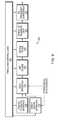
- FIG. 1is a schematic block diagram of a multi-point communications system having a plurality of remote service units disposed at a plurality of secondary sites wherein each of the remote service units comprises a receiver having an improved receiver architecture.
- FIG. 2is a block diagram of illustrative embodiments of the head end unit and a remote service unit of the communications system of FIG. 1 .
- FIG. 3illustrates two symbol constellations that are transmitted in two separate frequency bins in accordance with OFDM/DMT data modulation techniques.
- FIGS. 4 and 5illustrate exemplary bandwidth allocations for the local cable system and the cable telephony system, respectively.
- FIGS. 6-8illustrate various embodiments of the receiver of the remote service unit at various levels of detail.
- FIGS. 9-11Billustrate various embodiments of the transmitter of the remote service unit at various levels of detail.
- FIGS. 12-15illustrate various aspects of one embodiment of a partial sequence filter that may be used in either the head end unit or the remote service unit.
- FIGS. 16-18illustrate one way in which the head end unit and a newly added remote service unit can initialize communications.
- FIG. 1is a block diagram of a multi-point communications system which may use a remote service unit having the improved receiver and transmitter architectures disclosed herein.
- the communications systemshown generally at 20 includes a head end unit (HE) 25 disposed at a primary site.
- the head end unitcommunicates with a plurality of remote service units (RSUs) 30 respectively disposed at a plurality of secondary sites, over a transmission medium 35 such as a coaxial cable.
- RSUsremote service units
- the digital communications system 20may, for example, be a cable telephony system.
- the head end unit 25is disposed at a cable television transmission facility while the remote service units 30 are disposed at individual customer locations, such as individual customer homes.
- the transmission medium 35would be the new or existing transmission cable used to transmit the cable television services.
- the head end unit 25 in a cable telephony networkis responsible for communicating with and interconnecting telephone calls between the plurality of remote service units 30 as well communicating with a central switching office 40 for sending and receiving telephone calls from sites exterior to the local cable television service area.
- FIG. 2A block diagram of one embodiment of a head end unit 25 and a remote service unit 30 is shown in FIG. 2 .
- the head end unit 25 and the remote service units 30each generally comprise respective baseband sections 45 , 50 and respective RF sections 55 , 60 .
- the baseband section 45 of the head end unit 25receives constellation data at one or more lines 65 and performs an Inverse Fast Fourier Transform on the received data.
- the transformed signalis modulated within the RF section 55 for transmission along the cable transmission 35 .
- the remote service units 30receive the RF modulated data from the cable transmission medium 35 in the respective RF section.
- the present system 20utilizes OFDM/DMT digital data modulation for exchanging communications data between the head end unit 25 and the remote service units 30 .
- Such OFDM/DMT digital data communicationsassign a particular amplitude, frequency, and phase for each transmitted “sub-symbol”.
- the transmitted “sub-symbol”represents ant or more information data bits that are to be transmitted between the units 25 and 30 .
- Each sub-symbolmay be represented by a point within a “constellation”, the point being transmitted at a given carrier frequency or “bin”.
- FIG. 3illustrates the use of two constellations 90 and 95 , each having sixteen constellation points that are capable of being transmitted within two separate frequency bins.
- the second constellation 95preferably having the same amplitude and phase designations for its sub-symbols as the first constellation 90 , is used to modulate a second carrier frequency f 2 .
- the resulting modulated signalsare combined into a single output symbol in which the individual sub-symbols are differentiated from one another based on their respective carrier frequencies or “bins”.
- FIG. 4there is shown an exemplary break-up of the bandwidth allocated to a local cable television service. As illustrated, the entire allocated bandwidth is further sub-allocated into smaller bandwidth portions for the transmission of selected services such as cable television, audio broadcasting, cable telephony, and other miscellaneous services.
- the bandwidth allocated for cable telephonyconstitutes the focus of further discussion.
- the digital communications system described hereincan be utilized in any multi-point digital data communications system.
- FIG. 5illustrates the bandwidth allocated, for example, to the cable telephony communications.
- the bandwidth of the exemplary embodimentmay be about 2 MHz with a center frequency of about 600 MHz.
- the bandwidthis divided into a plurality of frequency bins 100 , each bin carrying a sequence of sub-symbols corresponding to the data that is to be communicated.
- the head end unit 35sends and receives data to and from multiple remote service units 30 and must be capable of processing substantially all, if not all of the bins allocated to cable telephony transmission. Accordingly, the head end unit 25 must have a substantial amount of processing power. Such a high amount of processing power naturally gives rise to increased production, maintenance, and power costs.
- the remote service units 30require substantial processing power if they are to each process the entire bandwidth or number of bins allocated to the cable telephony communications and transmitted by the head end unit 25 .
- the present inventorshave recognized that many applications using multi-point, OFDM/DMT data communications do not require that the remote service units 30 process the entire number of bins transmitted by the transmitter at the primary site. Rather, as recognized by the present inventors, the remote service units 30 employed in many types of OFDM/DMT data communications systems, such as cable telephony systems, need only be capable of processing a limited number of bins of the entire number of bins transmitted by the head end unit 25 .
- the remote service units 30are designed to process substantially fewer bins than the entire number of bins transmitted by the head end unit 25 , More particularly, the receiver architecture of each RSU is particularly adapted to exclusively digitally process only a limited number of bins of the largest number of OFDM/DMT bins that are transmitted by the head end unit 25 .
- Remote service units 30 disposed at different secondary sitesare preferably designed to process different subsets of bins. More preferably, the particular subsets of bins processed by any remote service units are dependent on command transmissions received from the head end unit 25 .
- Such a receiver architecturehas several advantages. For example, the digital signal processing capability required by the receiver of each RSU is significantly reduced thereby making each RSU more economical to design, manufacture, and maintain. Additionally, each RSU consumes less power than would otherwise be required if each RSU had to process the complete number of bins sent by the head end unit 25 .
- the RF conversion section 115receives the RF signal from the transmission medium 35 through, for example, a splitter, and transposes the desired part of the OFDM/DMT spectrum containing the information that is to be recovered into a predetermined intermediate frequency (IF) pass band.
- IFintermediate frequency
- the RF conversionis achieved with a combination of mixers, filters, and frequency synthesizers.
- the IF-to-digital section 120is used to sample the IF analog signal output of the RF conversion section 115 and provide a digital output signal corresponding to fewer than all of the bins transmitted by the head end unit 25 .
- the resulting digital output signalcan thus be processed by the Fourier Transform section 125 using substantially less processing power than would otherwise be required to process the full number of bins.
- the desired output signalis achieved by band pass filtering the signal to provide a signal that comprises a subset of the original OFDM/DMT bins transmitted by the head end unit 25 .
- This filtered signalis then under-sampled such that the desired signal folds down to near base band via an aliasing process. Under-sampling permits the use of a lower frequency A-to-D conversion than would otherwise be required. Additionally, the under sampling reduces the number of digital samples that are generated, thereby reducing the amount of processing power required in subsequent digital processing steps in the Fourier Transform section 125 .
- the Fourier Transform section 125is used to take the Fourier transform of the sampled signal output from the IF-to-digital section 120 in order to obtain a frequency domain representation of the OFDM/DMT modulated signal. This can be achieved in anyone of multiple ways.
- the Fourier Transform section 125may include a digital signal processor that performs a Fourier Transform on the sampled data.
- the Fourier Transform implemented by the presently disclosed receiver 110is taken over a reduced number of bins. This results in significant cost and power savings.
- a further improvementcan be achieved in the case where the sampled signal received from the IF-to-digital section 120 contains more bins than any individual receiver needs to receive.
- a hardware correlatorcould be used to obtain a Fourier Transform of only the bin frequencies containing data that the receiver 110 is to recover. This permits further power and complexity reduction when the narrow band receive window is still somewhat larger than the needed bandwidth.
- this architectureallows the speed and power consumption to be scaled according to the number of bins any particular receiver needs to receive.
- the decoding and formatting section 130receives the processed output of the Fourier Transform section 125 and converts the received frequency domain constellation points into the corresponding data they represent thereby completing the recovery of the transmitted data.
- the decoding and formatting section 130also performs any error correction, digital equalization, slicing to bits, framing, and descrambling that is required.
- Such decoding and formattingis dependent on the framing and formatting used by the head end unit 25 in transmitting the data and may take on any form.
- phase compensationcan be implemented in the decoding and formatting section 130 to compensate for any differences between the mixing frequencies of the transmitter of the head end unit 25 and the mixing frequencies of the receiver of the remote service unit 30 .
- phase compensationcan be implemented by effectively rotating the phase of each received sub-symbol through a predetermined phase angle ⁇ , during each symbol period.
- the phase angle through which each sub-symbol is rotatedis a multiple of e ⁇ . For example, a first sub-symbol during a first symbol period T 1 is rotated by phase angle ⁇ , while the next sub-symbol received during a subsequent second symbol period T 2 is rotated by a phase angle equal to 2* ⁇ .
- the output from the decoding and formatting section 130is supplied to the input of one or both of an analog-to-digital section 132 and direct digital section 137 .
- the analog-to-digital section 132converts the digital information received from the decoding and formatting section 130 to an analog signal that may be supplied to various analog devices.
- the direct digital section 137provides an interface between the digital signal output of the decoding and formatting section 130 and any digital data devices.
- Such a decentralized architecturecould also require more pipelining with its associated memory.
- FIG. 7illustrates one manner in which the RF section 115 , the IF-to-digital section 120 , and a portion of the Fourier Transform section 125 can be implemented.
- the signal transmitted from the head end unit 25is received by a first bandpass filter 150 that, for example, has a wide pass band with end frequencies of about 470 MHz and 750 MHz.
- the signal from the bandpass filter 150is supplied to the input of a tuner 155 that has its characteristics determined by the output of a tuner synthesizer 160 that is tied to receive the output of a reference clock that, for example, has a clock frequency of about 4 MHz.
- the tuner 155mixes the signal from the bandpass filter 150 to a signal having a frequency of about 240 MHz.
- the output of the tuner 155is supplied to the input of a further filter 165 , a SAW filter in the illustrated embodiment.
- the output of SAW filter 165is supplied to an IF mixer 170 that transposes the signal to an intermediate frequency (IF) of, for example, 10.7 MHz.
- IFintermediate frequency
- the mixer 170performs the IF conversion by mixing the signal received from the SAW filter 165 with the signal generated by oscillator 175 .
- the signal generated by the oscillator 175is synchronized to the reference clock signal received on line 180 .
- the output of the digital processing circuit 205may be supplied to the inputs of one or more D/A converters or CODECs that convert the data contained in the received symbols to one or more analog output signals, such as audio voice signals, that can be heard by a person engaged in a telephone conversation.
- one or more D/A converters or CODECsthat convert the data contained in the received symbols to one or more analog output signals, such as audio voice signals, that can be heard by a person engaged in a telephone conversation.
- FIG. 8illustrates one embodiment of a hardware correlator 210 that may be used in the Fourier Transform section 125 .
- the illustrated hardware correlator 210is designed to correlate nine frequency bins within the total bandwidth of frequency bins that are provided in digital format at the output of the A/D converter 190 of, for example, the IF-to-digital circuit 120 .
- the correlator 210includes a multiplier section 215 , a frequency generator section 220 , and an accumulator section 225 . As shown, the multiplier section 215 receives the digital data that is output from the IF-to-digital section 125 and multiplies each value by the sine and cosine value of each of nine frequency bins.
- the direct digital interface unit 310interfaces with any type of device that provides a signal that is already in digital format.
- the direct digital interface unit 310might have a serial interface for receiving data, as in a modem application.
- the unit 310might also receive data from a system CPU to be sent to the receiver of the head end unit 25 .
- the transmitter 300also includes a data interface unit 315 .
- the data, interface unit 315receives data from any combination of the following: sampled analog data from the output of the analog-digital interface unit 305 , direct digital data from the output of the direct digital interface unit 310 , or other digital data sources that, for example, provide system communication information generated from within or without the data interface unit 315 .
- the data interface unit 315formats the data received from these data sources into a single data stream. Tasks such as data framing, scrambling, error correction coding, CRC generation, data synchronization, and stuffing may be performed by the data interface unit 315 as part of the formatting function.
- the data interface unit 315may group the data into words that represent the unique constellation points to be transmitted.
- the specific formatting operations executed by the data interface unit 315are dependent on the particular requirements of the communications system in which the remote service unit 30 is employed.
- the serial data stream output from the data interface unit 315is supplied to the input of the transmit engine circuit 320 .
- the data that the transmit engine circuit 320 receivesincludes one constellation point for each OFDM/DMT bin of the reduced set of bins that is active during a single symbol time.
- the transmit engine circuit 320is responsible for calculating the Inverse Fourier Transform on the data stream that is to be modulated and for producing a time domain sequence for each symbol along with any cyclic prefix.
- systems using OFDM/DMT modulationperforms this function using an IFFT that is implemented, for example, with a digital signal processor.
- a multi-point applicationsuch as the communication system disclosed herein, only a limited number of the possible frequencies or bins are used by each secondary transmitter. Given that only a portion of the total available transmission bandwidth is utilized, the disclosed secondary transmitter architecture is more efficient and cost-effective.
- the time domain sequenceis generated by modulated direct digital synthesis, sample by sample. In addition to reducing the complexity of the transmitter, this operation reduces system latency.
- the time domain sequence for a given symbolis created by generating sine waves, sample by sample, and adding them together. The frequency determines the bin in which the data will be received. The phase and amplitude are used to convey the data intelligence.
- the preferred embodiment of the systemis such that there are 256 bins between 0 Hz and the Nyquist frequency. This is typical in OFDM/DMT systems. That is, the spectrum between 0 Hz and the Nyquist frequency is divided into a number of bins wherein the number is a power of 2, i.e. 2 n where n is an integer. This facilitates the use of FFTs and IFFTs.
- the presently disclosed transmitter 300preferably uses a Nyquist frequency that is greater than the transmit bandwidth, thereby leaving a number of bins turned off on each edge. Such a transmission scheme provides a natural filtering effect at the edges of the bandwidth. In the preferred embodiment, 209 bins fit within the allocated transmit bandwidth. All additional eight bins are turned off on either end of that bandwidth to leave some transition bandwidth for filters.
- the transmitter 300may utilize a digital filter 325 that receives the output of the transmit engine circuit 320 .
- This optional filterperforms any desired digital filtering of the output stream and, for example, may be useful in further limiting the bandwidth of the signal.
- the meter 325may be, for example, a digital partial sequence meter with reduced complexity.
- the digital sequence output from either the digital filter 325 or the transmit engine circuit 320is supplied to the input of a digital-to-baseband converter or a digital-lo-IF converter 330 depending on whether the signal output is at an IF or at baseband.
- the converter 330includes components that perform digital-to-analog conversion and analog filtering. If the output is at an IF, a bandpass filter centered around any image of the output spectrum may be employed. This results in an IF signal that is more easily processed in subsequent operations.
- the output of the converter 330is supplied to the input of an RF frequency converter 335 .
- the RF frequency converter 335shifts the OFDM/DMT spectrum from IF or baseband to the desired RF frequency.
- the RF frequency converter 335may be implemented using a combination of mixers, filters, and frequency synthesizers to implement the conversion functions and provides an OFDM/DMT output that is suitable for transmission along the transmission medium.
- Timing and control of the transmitter system 300is provided by a common timing and control logic circuit 340 .
- a centralized timing and control circuit 340is used in the illustrated embodiment. This function, however, could also be performed in a decentralized way. If decentralized timing and control are utilized, the timing and control circuits would likely be more complex to deal with the resulting lack of synchronism between circuits. It could also require more pipe lining with its associated memory.
- FIG. 10One embodiment of digital transmission circuitry that may be used to generate the digital OFDM/DMT signal for subsequent D/A conversion and RF modulation is set forth in FIG. 10 .
- the digital transmission circuitry 350 illustrated heremay be used to implement, inter alia, the transmit engine circuit 320 of FIG. 9 .
- the digital transmission circuitry 350accepts digital data from, for example, the output of first and second CODECs respectively associated with individual first and second telephones.
- the circuitry 350may receive digital data that is to be transmitted in embedded control channels within the transmitted signal, each of the embedded control channels being respectively associated with one of the first and second telephones, the digital data output from the CODECs and on the embedded control channels are combined together by a combiner circuit 360 into two separate data groups, illustrated here as DATA 1 and DATA 2 .
- the presently disclosed embodimentprovides the capability of generating OFDM/DMT transmissions in one or more of nine frequency bins.
- Each data group DATA 1 and DATA 2is supplied to the input of an encoder logic circuit 365 .
- the encoder logic circuit 365divides the data groups into symbol groups and maps each symbol to a point of a constellation to obtain a phase and amplitude for each symbol.
- the amplitude information for each symbolis provided on one or more lines 370
- the phase information for each symbolis provided on one or more lines 375 .
- the sine table ROM 405contains the digital data representation of a sine wave, or selected portion thereof, shown here as a quarter wave table, in successive addressable memory locations.
- the successive, addressable memory locations of the sine table ROM 405are addressed in a specific manner to provide a digital output signal having the phase and frequency characteristics of the symbol that it is to represent.
- the phase of the sine wave represented by the digital output signalis dependent on the memory location that is first addressed at the beginning of the symbol period while the frequency of the sine wave is determined by the step size used to address successive memory locations within the sine table ROM.
- the selection of the memory location that is first addressed at the beginning of a symbol periodis dependent on the phase information on output lines 375 of the encoder logic circuit 365 .
- the phase informationis supplied to the start address ROM 380 which provides a start address which is output to the address storage register 395 .
- the step size through which the memory locations within the sine table ROM 405 are to be cycledis determined by the value at the output of the step size storage register 385 .
- the step size storage register 385includes one or more memory storage locations that are accessible to a microcontroller or DSP.
- the microcontrollerdetermines the step sizes that are stored in the step size storage register 385 based on the desired symbol carrier frequency bins that can be used—the larger the step size, the higher the carrier frequency.
- the step size register 385includes nine register locations for the nine bins that can be transmitted.
- the step size register 385is programmed by the microcontroller based on commands received from the head end unit 25 .
- the step size valueis supplied at one or more output lines 410 of the step size register 385 to the input of the adder 390 .
- the adder 390functions to provide the address signals that are used to successively address the memory locations of the sine table ROM 405 . Accordingly, the output of the address register 395 is fed back to the input of the adder 390 so that the sine table ROM 405 selection address is incremented by the appropriate step size on each successive addressing cycle corresponding to the particular frequency bins.
- the address modifier 400includes combinatorial and/or programmed logic circuits that perform calculations that ensure that the address value supplied to the sine table ROM 405 falls within an acceptable range and thereby accesses the appropriate portion of the wave. Such calculations ensure that the newly calculated address start at the appropriate portion of the sine table ROM 405 without generating an undesired discontinuity.
- the output of the sine table ROM 405is supplied to the input of a multiplier 420 .
- the multiplier 420accepts each digital data value that is output from the sine table ROM 405 and multiplies each value by the corresponding amplitude factor as determined from the amplitude information output of the encoder logic circuit 365 received along lines 370 .
- the sine table ROM 405 of the presently disclosed embodimentincludes only positive values, some circuitry must be provided to generate the negative portions of the wave.
- the output of the multiplier 420is supplied to a two's complement converter 430 and the most significant bit (MSB) from the address register 395 is used to signal the converter 430 to either through-connect the output of the multiplier 420 to an accumulator 440 or perform a two's complement operation on the output before providing it to the accumulator 440 .
- the accumulator 440adds all of the data points for the nine frequency bins that are generated during a single sample period and provides the resulting data on output lines 445 .
- timing and control inputs from the timing and control logic circuitry 340are not illustrated in FIG. 10 . Such inputs have been omitted in order to simplify the figure. Given the foregoing description, the timing and control operations can be readily derived.
- FIG. 11shows yet a further embodiment of the basic elements of the transmit engine shown in FIG. 9 .
- a full wave sine table ROM 500is utilized. Accordingly, the two's complement circuit 430 and the address modifier 400 are not provided.
- the digital filterredefine may be a partial sequence filter.
- the basic operation of a partial sequence filter 600can best be understood in connection with the waveforms illustrated in FIG. 12 .
- Line 605 of FIG. 12is a time domain signal representing one bin of an OFDM/DMT signal over three symbol periods. As shown, the beginning of each symbol signal is generally discontinuous to the preceding symbol signal and the end of each symbol signal is generally discontinuous to the beginning of the subsequent symbol signal. The discontinuities between symbols result in a generally broadband frequency spectrum which the digital filter 325 is designed to limit.
- the digital filter 325may be implemented as a finite impulse response (FIR) filter.
- FIRfinite impulse response
- a FIR filteris expected to process all of the digital samples provided by the transmit engine of the preceding stage. That is, all of the digital samples that are output from the transmit engine 320 are supplied to the input of and are processed by the FIR filter.
- Such a FIR filterthus requires a substantial amount of processing power.
- a 101 tap FIR filter responsive to a digital signal having a 10 MHz sampling frequencywould typically require approximately 1000 MIPS to perform the requisite multiplication. If the filter is symmetric, the complexity can be reduced so that 500 MIPS are required to perform this multiplication. In either instance, such a filter implementation may be quite costly, particularly in a multi-point digital communications system.
- the present inventorshave recognized a unique characteristic of OFDM/DMT signals and have used this characteristic to reduce the complexity of the filter.
- the OFDM/DMT signallooks like a tone during a substantial portion of the middle of the symbol period.
- the discontinuities that broaden the frequency spectrum of the transmitted symbolsoccur only at the beginning portion and end portion of the symbol period.
- the inventorshave recognized that, when the taps of a FIR filter are inside of a single symbol, the filter's output is approximately the same as the input. This relationship exists when the FIR filter has unity gain and exhibits linear phase in the pass band. As such, a FIR filter does not alter signals within the pass band and need only perform filtering of samples taken at the beginning portion and end portion of a symbol period.
- the filter 325may be a partial sequence filter that digitally filters only a select portion of the samples of a symbol period.
- the partial sequence filterdigitally filters only the samples occurring at a beginning portion of the sample period and an end portion of the sample period. For example, if a 101 tap FIR filter is used in the disclosed system, it becomes possible to only digitally process 100 of the 1100 samples in every symbol period, 50 samples at the beginning portion of a symbol period and 50 samples at the end portion of a symbol period.
- Such an approachreduces the number of multipliers that must be executed by a factor of 100/1100, resulting in only approximately 9% of the complexity that would otherwise be required if all 1100 samples were processed, The result is a reduction from 1000 MIPS to 91 MIPS.
- the complexitymay be further reduced using standard filtering techniques that can be used for FIR filters with symmetric taps. Since sample 1 is multiplied by the same coefficient as used with sample 101 , sample 1 may be added to sample 101 before multiplication. Likewise, sample 2 is multiplied by the same coefficient as sample 100 and, as such, sample 2 may be added to sample 100 before multiplication. This symmetrical relationship can be used for approximately all of the processed samples. Application of this principle further reduces the complexity to 45 MIPS.
- the partial sequence filteringcan be implemented by dedicated hardware or with a digital signal processor.
- a digital signal processor within the head end unit 25may be used to implement the partial sequence filter.
- a dedicated hardware circuitsuch as the one illustrated in FIG. 13 , may be used to implement the partial sequence filter.
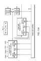
- FIG. 13illustrates an exemplary implementation of the partial sequence filter.
- the partial sequence filtershown generally at 600 , receives blocks of data from a preceding IFT process, such as the process performed by the transmit engine 320 .
- the IFTtakes the inverse Fourier transform for a set of constellation points that make up a given symbol. A new block of samples is generated once for every symbol. After each symbol undergoes an IFT, the time domain data is written to either symbol buffer 610 or symbol buffer 615 , alternately. It may be advantageous to use a cyclic prefix at the start of every symbol. Such a cyclic prefix is described below. In such instances, the end of the sequence generated by the preceding IFT process is tacked onto the beginning of the time sequence and functions as the cyclic prefix.
- the partial sequence filter 600is comprised of symbol buffers 610 and 615 , a filter engine, shown generally at 620 , a multiplexer 625 , and an output register 630 .
- the digital data for each symbolis alternately stored in either symbol buffer 610 or symbol buffer 615 .
- the IFT processed symbol data for each symbolis supplied from one or the other of the symbol buffers 610 , 615 to either the input of the filter engine 620 for filter processing and subsequent supply, for example, to the digital-to-baseband (or IF) circuit 330 , through output register 630 or directly, without filtering, for supply to circuit 330 through output register 630 .
- the transmit engine 620is comprised of registers 635 and 640 , adder 645 , digital multiplier 650 , coefficient data table memory 655 , adder 660 , feedback register 665 , and engine output buffer 670 . Together, the adder 660 and feedback register 665 constitute an accumulator 675 .
- the filteris symmetric so that the coefficient for FIR filter tap 101 is the same as the coefficient for FIR filter tap 1 . Likewise, the coefficient for tap 100 is the same as that of tap 2 .
- the sample needed for tap 101is first latched into register 635 .
- the sample needed for tap 1is then latched into register 640 .
- the two samplesare added to one another by adder 645 .
- the resulting sumis supplied to the input of digital multiplier 650 where it is multiplied by the coefficient for tap 1 as supplied from the coefficient table memory 655 .
- the resulting digital valueis effectively stored in register 665 of the accumulator 675 (the initial value contained in register 665 is assumed to be zero).
- the same basic operationis next performed for the samples needed for taps 2 and 100 , but using the coefficient for tap 2 as supplied from the coefficient table memory 655 .
- the digital value resulting from the multiplication with the coefficient for tap 2is added to the digital value result of the previous multiplication that is already stored in register 665 by the accumulator 675 .
- this operationis repeated for a total of 50 times.
- the 51 st operationproceeds in a slightly different matter. More particularly, the data corresponding to tap 51 is stored in register 635 , while register 640 is loaded with a zero. These values are added to one another by adder 645 and are multiplied by tap coefficient 51 at multiplier 650 . The resulting value is added to the digital value that is already present in register 665 . The result is again latched into register 665 . As such, register 665 contains a filtered output value. This filtered output value is subsequently stored in the engine output buffer 670 for subsequent supply to the D/A converter of the digital-to-baseband (or IF) circuit 330 through multiplexer 62 history 5 and register 630 .
- FIGS. 14 A-Eillustrate data passing through the filter engine 620 of the illustrated partial sequence filter 600 having a 101 tap FIR filter. To obtain an output sample from the filter, each tap multiplies the corresponding data and the results of these multiplication operations are summed together.
- the data samplesare denoted as X: Y, where X represents the symbol number and Y represents the sample number for the particular symbol. For example, the notation 1:1000 represents the 1000 th sample of symbol number one.
- Each tapis denoted by a numbered box, and the particular data sample present at a given tap is shown therein to indicate the positions of the data samples within the filter at a given time. For example, at the time designated by the filter state represented in FIG. 14A , tap 1 is multiplying sample 2:0, tap 2 is multiplying sample 1:1099, etc. . . . .
- FIGS. 14 B-Eillustrate subsequent operations of the filter. More particularly, FIG. 14B illustrates the state of the filter in an operation immediately subsequent to the filter state shown in FIG. 14A .
- FIG. 14Cillustrates the state of the filter for the last sample from symbol 1 (1:1099) that needs to be replaced.
- FIG. 14Dshows the state of the filter for the first sample from symbol 2 (2:0) that needs to be replaced on the way to the D/A converter of the circuit 330 .
- FIG. 14Eshows the state of the filter for the last sample that needs to be replaced in the first fifty samples of symbol number 2 (2:49). The last 50 samples of symbol number 2 also require filtering and would be processed accordingly.
- the partial sequence filtershould be designed to have an amplitude and phase effect in the pass band. Absent such effects, a significant discontinuity will exist between the filtered and unfiltered data. Such discontinuities may result in both in-band and out-of-band noise.
- Timing, address generation, and control logic circuit 690coordinates the reading and writing of the symbol buffers 610 and 615 with receipt of data samples from the preceding IFT process to ensure that the IFT process is complete and that the samples are at least beginning to be written to one of the symbol buffers before those samples are needed at the output register 630 .
- the control logic unit 690should also ensure that the samples in one or the other of symbol buffers 610 , 615 are supplied to either the filter engine 620 or the output register 630 before they are overwritten by the symbol data from the subsequent IFT operation. Additionally, the control logic unit 690 should coordinate movement of the data through the partial sequence filter so that data is available to the filter engine 620 at a rate which allows the filter engine to run at a moderate rate over the majority of the symbol period.
- the control logic unit 690should control the relationship between the read and write pointers associated with each of the symbol buffers 610 and 615 and the engine output buffer 670 so as to minimize latency. However, latency can be added to the system design to reduce timing constraints.
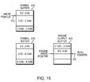
- FIG. 15illustrates the relationship between some of the buffer read and write pointers. In the illustration, the timing between the pointers is shown near the buffer boundaries.
- the read pointer 705 that gets the data from the engine output buffer 670 for supply to the output register 630is also used to read data from each of symbol buffers 610 and 615 .
- the read pointer 705gets data samples X:50-X:1049 from one or the other of symbol buffers 610 and 615 (depending on where symbol number X is stored), and gets data samples X:0-X:49 and X:1050-X:1099 from the engine output buffer 670 .
- the appropriate samplesshould always be available to the output register 630 for subsequent processing. To reduce latency, however, the samples are processed as close to just-in-time as practical.
- the exemplary pointer locations illustrated in FIG. 15show the pointers near crossover points to illustrate how close the pointers can come to one another.
- the filter engine 620has just completed the writing of the outputs that will replace sample 4:49 and has begun processing the 4:1050 replacements.
- the read pointer 705is just beginning to read sample 4:49 from the engine output buffer 670 .
- the write pointer 710has just finished writing sample 5:49 so that the filter engine has every sample required to process the 4:1050 replacement.
- FIGS. 16-18illustrate one manner of initiating communications between a newly added or powered-up remote service unit 30 and the head end unit 25 .
- the remote service unit 30first synchronizes its internal clocks with the head end unit 25 .
- FIG. 2shows a pilot tone added by the head end unit 25 to a predetermined bin output that is transmitted to the remote service units 30 .
- the pilot toneis extracted from the received signal by the receiver of the remote service unit 30 and used, for example, as a reference signal for a phase-locked-loop circuit 600 .
- the output of the phase-lacked-loop 600is provided to the input of a voltage controlled oscillator 605 which generates the reference clock for the remote service unit 30 .
- the remote service unit 30acquires its symbol timing at step 730 .
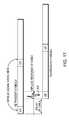
- symbol timingmay be acquired is illustrated in FIG. 17 which shows an impulse signal 800 being added by the head end unit 25 to the cyclic prefix CP of each symbol transmission.
- the impulse signal 800reverses polarity with each successive symbol transmission so that a positive polarity impulse signal is added to the cyclic prefix of one symbol transmission while a negative polarity impulse signal is added to the cyclic prefix of the subsequent symbol transmission.
- the receiver 110 of the remote service unit 30finds the time location of the transmitted impulse signal by sampling, at a predetermined rate, the symbols that it receives and alternately adding and subtracting the samples of individual sample periods over several symbol periods. For example, the receiver 110 may sample the received signal at a rate of 100 samples per symbol period to generate samples SA 0 . . . SA 99 during a first symbol period, SB 0 . . . SB 99 samples that it receives during a subsequent symbol period, SC 0 . . . SC 99 samples that it receives during a subsequent third symbol period, and so on.
- the receiver 110can then make the requisite adjustments to ensure that it receives the symbols in proper alignment.
- the received samplesare preferably multiplied by cos ⁇ where ⁇ , is n* ⁇ , (see phase compensation discussion above) and n is the symbol number.
- the downstream communications channelcomprises one or more bins used by the head end unit to establish initial communications with receivers 110 .
- setup of the remote service unit communicationsproceeds to step 750 .
- the newly added or newly powered-up remote service unit 30must inform the head end unit 25 that it is in need of registration whereby, among other things, the head end unit 25 allocates bins to the receiver and transmitter of the remote service unit 30 .
- One problem associated with any initial transmission from the remote service unit 30 to the head end unit 25is that the transmit boundary of the newly added remote service unit is not aligned with the transmit boundary of the other remote service units on the system. Thus, any misaligned transmission from the newly added remote service unit may corrupt the transmissions received from other remote service units.
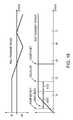
- FIG. 18One way of overcoming the problem of initial misalignment is illustrated in FIG. 18 .
- a predetermined upstream binis allocated as an upstream multi-access channel.
- the transmitter of the newly added remote service unittransmits information on the upstream multi-access channel in the illustrated manner by altering both its transmit phase and transmit power.
- the newly added remote service unitfirst maintains its transmit phase at a predetermined phase while gradually increasing the transmit power.
- the head end unit 25can receive such a signal without a corresponding corruption of the data transmitted from the other remote service units. Once the head end unit 25 detects the transmission from the newly added remote service unit, it can perform any requisite processing of the received signal, such as equalization thereof.
- the newly added remote service unitbegins to slowly vary the phase of its transmitted signal in the illustrated manner.
- the transmit phaseis varied so as to convey intelligent data to the head end unit 25 .
- the head end unit 25samples the phase of the signal that it receives on the upstream multi-access channel and uses the data, for example, to identify the newly added remote service unit.
- the head end unit 25commands the newly added remote service unit, via the downstream communications channel, to send, for example, an impulse signal of a predetermined amplitude on the upstream communications channel at the symbol rate.
- the bead end unit 25detects the time position of the impulse signal and provides the remote service unit with the information necessary to align its symbol transmissions with the symbol transmissions of the other remote service units. Further communications between the newly added remote service unit and the head end unit 25 can take place on the upstream and downstream communications channels until the head end unit 25 allocates the transmit and receive bills that are to be assigned to the newly added remote service unit and instructs it accordingly.
- the head end unit 25 and the newly added remote service unitcarry out their standard communications at step 760 .
- the present systemcan be designed to transmit and receive either 4 point constellations or 16 point constellations in a given bin depending on the signal-to-noise ratio in the communications system at the bin frequency. This determination is made by the head end unit 25 and the remote service units transmitting and/or receiving in that bin are instructed accordingly. In bins having a low signal-to-noise ratio, it is preferable to use 4 point constellations. In bins having a high signal-to-noise ratio, it is preferable to use 16 point constellations.
- the embodiments of the remote service units described hereinsend and receive data in nine bins, respectively.
- four binsare needed by each of the two phones at the customer site to transmit data and four bins are needed by each of the two phones at the customer site to receive data.
- a total of eight binsare thus required in high noise conditions for each telephone receiver and transmitter, respectively.
- the further ninth binmay, for example, be used to facilitate a bin swapping function.
Landscapes
- Engineering & Computer Science (AREA)
- Signal Processing (AREA)
- Computer Networks & Wireless Communication (AREA)
- Physics & Mathematics (AREA)
- Discrete Mathematics (AREA)
- General Physics & Mathematics (AREA)
- Mathematical Physics (AREA)
- Quality & Reliability (AREA)
- Digital Transmission Methods That Use Modulated Carrier Waves (AREA)
- Cable Transmission Systems, Equalization Of Radio And Reduction Of Echo (AREA)
Abstract
Description
Claims (21)
Priority Applications (1)
| Application Number | Priority Date | Filing Date | Title |
|---|---|---|---|
| US13/012,683US8243583B2 (en) | 1996-08-22 | 2011-01-24 | OFDM/DMT/digital communications system including partial sequence symbol processing |
Applications Claiming Priority (6)
| Application Number | Priority Date | Filing Date | Title |
|---|---|---|---|
| US08/700,779US5790514A (en) | 1996-08-22 | 1996-08-22 | Multi-point OFDM/DMT digital communications system including remote service unit with improved receiver architecture |
| US08/772,321US6118758A (en) | 1996-08-22 | 1996-12-23 | Multi-point OFDM/DMT digital communications system including remote service unit with improved transmitter architecture |
| US09/379,676US6804192B1 (en) | 1996-08-22 | 1999-08-24 | OFDM/DMT digital communications system including partial sequence symbol processing |
| US10/883,916US8547823B2 (en) | 1996-08-22 | 2004-07-02 | OFDM/DMT/ digital communications system including partial sequence symbol processing |
| US11/982,449US7898935B2 (en) | 1996-08-22 | 2007-10-31 | OFDM/DMT/digital communications system including partial sequence symbol processing |
| US13/012,683US8243583B2 (en) | 1996-08-22 | 2011-01-24 | OFDM/DMT/digital communications system including partial sequence symbol processing |
Related Parent Applications (1)
| Application Number | Title | Priority Date | Filing Date |
|---|---|---|---|
| US11/982,449DivisionUS7898935B2 (en) | 1996-08-22 | 2007-10-31 | OFDM/DMT/digital communications system including partial sequence symbol processing |
Publications (2)
| Publication Number | Publication Date |
|---|---|
| US20110116571A1 US20110116571A1 (en) | 2011-05-19 |
| US8243583B2true US8243583B2 (en) | 2012-08-14 |
Family
ID=33101562
Family Applications (6)
| Application Number | Title | Priority Date | Filing Date |
|---|---|---|---|
| US08/772,321Expired - LifetimeUS6118758A (en) | 1996-08-22 | 1996-12-23 | Multi-point OFDM/DMT digital communications system including remote service unit with improved transmitter architecture |
| US09/379,676Expired - LifetimeUS6804192B1 (en) | 1996-08-22 | 1999-08-24 | OFDM/DMT digital communications system including partial sequence symbol processing |
| US09/659,194Expired - LifetimeUS6912194B1 (en) | 1996-08-22 | 2000-09-11 | Digital communication transmission techniques |
| US10/883,916Expired - Fee RelatedUS8547823B2 (en) | 1996-08-22 | 2004-07-02 | OFDM/DMT/ digital communications system including partial sequence symbol processing |
| US11/982,449Expired - Fee RelatedUS7898935B2 (en) | 1996-08-22 | 2007-10-31 | OFDM/DMT/digital communications system including partial sequence symbol processing |
| US13/012,683Expired - Fee RelatedUS8243583B2 (en) | 1996-08-22 | 2011-01-24 | OFDM/DMT/digital communications system including partial sequence symbol processing |
Family Applications Before (5)
| Application Number | Title | Priority Date | Filing Date |
|---|---|---|---|
| US08/772,321Expired - LifetimeUS6118758A (en) | 1996-08-22 | 1996-12-23 | Multi-point OFDM/DMT digital communications system including remote service unit with improved transmitter architecture |
| US09/379,676Expired - LifetimeUS6804192B1 (en) | 1996-08-22 | 1999-08-24 | OFDM/DMT digital communications system including partial sequence symbol processing |
| US09/659,194Expired - LifetimeUS6912194B1 (en) | 1996-08-22 | 2000-09-11 | Digital communication transmission techniques |
| US10/883,916Expired - Fee RelatedUS8547823B2 (en) | 1996-08-22 | 2004-07-02 | OFDM/DMT/ digital communications system including partial sequence symbol processing |
| US11/982,449Expired - Fee RelatedUS7898935B2 (en) | 1996-08-22 | 2007-10-31 | OFDM/DMT/digital communications system including partial sequence symbol processing |
Country Status (1)
| Country | Link |
|---|---|
| US (6) | US6118758A (en) |
Cited By (2)
| Publication number | Priority date | Publication date | Assignee | Title |
|---|---|---|---|---|
| US8547823B2 (en) | 1996-08-22 | 2013-10-01 | Tellabs Operations, Inc. | OFDM/DMT/ digital communications system including partial sequence symbol processing |
| US8665859B2 (en) | 1996-08-22 | 2014-03-04 | Tellabs Operations, Inc. | Apparatus and method for clock synchronization in a multi-point OFDM/DMT digital communications system |
Families Citing this family (33)
| Publication number | Priority date | Publication date | Assignee | Title |
|---|---|---|---|---|
| US5790514A (en)* | 1996-08-22 | 1998-08-04 | Tellabs Operations, Inc. | Multi-point OFDM/DMT digital communications system including remote service unit with improved receiver architecture |
| US6370156B2 (en)* | 1997-01-31 | 2002-04-09 | Alcatel | Modulation/demodulation of a pilot carrier, means and method to perform the modulation/demodulation |
| US7440498B2 (en) | 2002-12-17 | 2008-10-21 | Tellabs Operations, Inc. | Time domain equalization for discrete multi-tone systems |
| US6631175B2 (en) | 1998-04-03 | 2003-10-07 | Tellabs Operations, Inc. | Spectrally constrained impulse shortening filter for a discrete multi-tone receiver |
| DK1068704T3 (en) | 1998-04-03 | 2012-09-17 | Tellabs Operations Inc | Impulse response shortening filter, with additional spectral constraints, for multi-wave transfer |
| US6795424B1 (en)* | 1998-06-30 | 2004-09-21 | Tellabs Operations, Inc. | Method and apparatus for interference suppression in orthogonal frequency division multiplexed (OFDM) wireless communication systems |
| US6693957B1 (en)* | 1998-12-31 | 2004-02-17 | Nortel Networks Limited | Adaptive front end for discrete multitone modem |
| US7088680B1 (en)* | 1999-01-11 | 2006-08-08 | Advanced Micro Devices, Inc. | System and method for digital communication via a time division multiplexed serial data stream |
| US6529868B1 (en) | 2000-03-28 | 2003-03-04 | Tellabs Operations, Inc. | Communication system noise cancellation power signal calculation techniques |
| AUPR048500A0 (en)* | 2000-10-02 | 2000-10-26 | Nec Australia Pty Ltd | Radio frequency communications |
| US7333422B2 (en)* | 2003-09-12 | 2008-02-19 | Zarbana Digital Fund Llc | Optimized FFT/IFFT module |
| CA2337737A1 (en)* | 2001-02-05 | 2002-08-05 | Catena Networks Canada Inc. | Improved method for adapting the receiver demodulation structure according to the transmitter ifft size, in dmt-based adsl modems |
| US7020218B2 (en)* | 2001-06-18 | 2006-03-28 | Arnesen David M | Sliding-window transform with integrated windowing |
| DE10239810A1 (en)* | 2002-08-29 | 2004-03-11 | Siemens Ag | Method and transmission device for transmitting data in a multi-carrier system |
| US7020177B2 (en)* | 2002-10-01 | 2006-03-28 | Intel Corporation | Method and apparatus to transfer information |
| DE10310810B3 (en)* | 2003-03-12 | 2004-10-14 | Infineon Technologies Ag | Data symbol filtering device for decision-based data processing system within communications receiver using comparison of received data symbols with required data symbols by median filter |
| US8204149B2 (en) | 2003-12-17 | 2012-06-19 | Qualcomm Incorporated | Spatial spreading in a multi-antenna communication system |
| US8169889B2 (en) | 2004-02-18 | 2012-05-01 | Qualcomm Incorporated | Transmit diversity and spatial spreading for an OFDM-based multi-antenna communication system |
| US8285226B2 (en)* | 2004-05-07 | 2012-10-09 | Qualcomm Incorporated | Steering diversity for an OFDM-based multi-antenna communication system |
| US8923785B2 (en) | 2004-05-07 | 2014-12-30 | Qualcomm Incorporated | Continuous beamforming for a MIMO-OFDM system |
| US7978649B2 (en)* | 2004-07-15 | 2011-07-12 | Qualcomm, Incorporated | Unified MIMO transmission and reception |
| US7251577B2 (en)* | 2004-07-19 | 2007-07-31 | Tektronix, Inc. | Realtime power mask trigger |
| KR100465307B1 (en)* | 2004-09-02 | 2005-01-13 | 이승한 | Data communication Device in CATV network |
| KR100769671B1 (en)* | 2005-02-21 | 2007-10-24 | 삼성전자주식회사 | MB-OPDM transceiver and signal processing method thereof |
| US8543070B2 (en) | 2006-04-24 | 2013-09-24 | Qualcomm Incorporated | Reduced complexity beam-steered MIMO OFDM system |
| JP4826837B2 (en)* | 2006-09-15 | 2011-11-30 | 日本電気株式会社 | Packet delivery system and packet delivery method |
| US20080316911A1 (en)* | 2007-06-21 | 2008-12-25 | Leif Wilhelmsson | Simultaneous Cell Group and Cyclic Prefix Detection Method, Apparatus and System |
| CN102652407A (en)* | 2009-12-18 | 2012-08-29 | 日本电气株式会社 | Transmission system, transmission device, receiving device, transmission method, and computer program |
| WO2014121283A2 (en)* | 2013-02-04 | 2014-08-07 | Spectra7 Microsystems Ltd | Methods and systems for achieving higher video throughput and/or quality |
| US9313069B2 (en)* | 2014-07-22 | 2016-04-12 | Zenith Electronics Llc | OFDM processing system and method |
| US10383122B2 (en) | 2017-03-08 | 2019-08-13 | Casa Systems, Inc. | Dynamic sharing of OFDMA and ATDMA signals |
| US11012211B2 (en)* | 2019-10-07 | 2021-05-18 | Jaihyung Cho | Method for transmitting reference signal and apparatus using the same |
| WO2021154132A1 (en) | 2020-01-31 | 2021-08-05 | Telefonaktiebolaget Lm Ericsson (Publ) | Methods and apparatuses for windowing-based adjacent channel filtering in an ofdm-based communication network |
Citations (94)
| Publication number | Priority date | Publication date | Assignee | Title |
|---|---|---|---|---|
| US3795772A (en) | 1972-05-01 | 1974-03-05 | Us Navy | Synchronization system for pulse orthogonal multiplexing systems |
| US4300229A (en) | 1979-02-21 | 1981-11-10 | Nippon Electric Co., Ltd. | Transmitter and receiver for an othogonally multiplexed QAM signal of a sampling rate N times that of PAM signals, comprising an N/2-point offset fourier transform processor |
| US4399329A (en) | 1981-11-25 | 1983-08-16 | Rca Corporation | Stereophonic bilingual signal processor |
| US4425665A (en) | 1981-09-24 | 1984-01-10 | Advanced Micro Devices, Inc. | FSK Voiceband modem using digital filters |
| US4535472A (en) | 1982-11-05 | 1985-08-13 | At&T Bell Laboratories | Adaptive bit allocator |
| US4618996A (en) | 1984-04-24 | 1986-10-21 | Avnet, Inc. | Dual pilot phase lock loop for radio frequency transmission |
| US4731816A (en) | 1985-05-20 | 1988-03-15 | Telebit Corporation | Ensemble modem structure for imperfect transmission media |
| US4817141A (en) | 1986-04-15 | 1989-03-28 | Nec Corporation | Confidential communication system |
| US4951279A (en) | 1987-10-20 | 1990-08-21 | Nec Corporation | Transceiver for use in earth station in satellite communications system |
| US4980897A (en) | 1988-08-12 | 1990-12-25 | Telebit Corporation | Multi-channel trellis encoder/decoder |
| US5014306A (en) | 1988-11-14 | 1991-05-07 | Transtream, Inc. | Voice and data telephone communication system and method |
| US5077727A (en) | 1989-05-29 | 1991-12-31 | Kabushiki Kaisha Toshiba | Broadband information communications network system with coherent optical data transmission lines |
| US5103459A (en) | 1990-06-25 | 1992-04-07 | Qualcomm Incorporated | System and method for generating signal waveforms in a cdma cellular telephone system |
| US5192957A (en) | 1991-07-01 | 1993-03-09 | Motorola, Inc. | Sequencer for a shared channel global positioning system receiver |
| US5206886A (en) | 1990-04-16 | 1993-04-27 | Telebit Corporation | Method and apparatus for correcting for clock and carrier frequency offset, and phase jitter in mulicarrier modems |
| US5216670A (en) | 1991-07-03 | 1993-06-01 | International Business Machines Corporation | Message stripping protocol for a communication network |
| US5228025A (en) | 1990-02-06 | 1993-07-13 | Centre National D'etudes Des Telecommunications | Method for the broadcasting of digital data, notably for radio broadcasting at a high bit-rate towards mobile receivers, with time-frequency interlacing and assistance in the acquisition of automatic frequency control, and corresponding receiver |
| US5233546A (en) | 1991-08-14 | 1993-08-03 | Hewlett-Packard Company | Anti-alias filtering apparatus for frequency domain measurements |
| US5253270A (en) | 1991-07-08 | 1993-10-12 | Hal Communications | Apparatus useful in radio communication of digital data using minimal bandwidth |
| US5285474A (en) | 1992-06-12 | 1994-02-08 | The Board Of Trustees Of The Leland Stanford, Junior University | Method for equalizing a multicarrier signal in a multicarrier communication system |
| US5323255A (en) | 1991-05-08 | 1994-06-21 | Alcatel N.V. | Transceiver arrangement using TDM to transmit assigned subcarrier waveforms |
| US5406627A (en) | 1990-08-06 | 1995-04-11 | Nec Home Electronics, Ltd. | Digital data cryptographic system |
| US5416767A (en) | 1993-02-08 | 1995-05-16 | U.S. Philips Corporation | Method of transmitting a data stream, transmitter and receiver |
| US5416801A (en) | 1992-07-08 | 1995-05-16 | U.S. Philips Corporation | Digital signal transmission system based on partitioning of a coded modulation with concatenated codings |
| US5444697A (en) | 1993-08-11 | 1995-08-22 | The University Of British Columbia | Method and apparatus for frame synchronization in mobile OFDM data communication |
| US5471464A (en) | 1993-07-26 | 1995-11-28 | Sony Corporation | Orthogonal frequency division multiplex demodulation apparatus |
| US5479447A (en) | 1993-05-03 | 1995-12-26 | The Board Of Trustees Of The Leland Stanford, Junior University | Method and apparatus for adaptive, variable bandwidth, high-speed data transmission of a multicarrier signal over digital subscriber lines |
| US5483529A (en) | 1993-02-08 | 1996-01-09 | U.S. Philips Corporation | Receiver |
| US5499271A (en) | 1991-04-11 | 1996-03-12 | Institut Fur Rundfunktechnik Gmbh | Method for broadcasting a digitally coded stream of data using an already occupied frequency spectrum |
| US5502749A (en) | 1993-03-30 | 1996-03-26 | Sony Corporation | Radio receiver apparatus and phase correcting method thereof |
| US5524001A (en) | 1994-02-07 | 1996-06-04 | Le Groupe Videotron Ltee | Dynamic cable signal assembly |
| US5530703A (en) | 1994-09-23 | 1996-06-25 | 3Com Corporation | Remote communication server with automatic filtering |
| US5539777A (en) | 1995-01-26 | 1996-07-23 | Motorola, Inc. | Method and apparatus for a DMT receiver having a data de-formatter coupled directly to a constellation decoder |
| US5548819A (en) | 1991-12-02 | 1996-08-20 | Spectraplex, Inc. | Method and apparatus for communication of information |
| US5553064A (en) | 1994-04-05 | 1996-09-03 | Stanford Telecommunications, Inc. | High speed bidirectional digital cable transmission system |
| US5557612A (en) | 1995-01-20 | 1996-09-17 | Amati Communications Corporation | Method and apparatus for establishing communication in a multi-tone data transmission system |
| US5559789A (en) | 1994-01-31 | 1996-09-24 | Matsushita Electric Industrial Co., Ltd. | CDMA/TDD Radio Communication System |
| US5568483A (en) | 1990-06-25 | 1996-10-22 | Qualcomm Incorporated | Method and apparatus for the formatting of data for transmission |
| US5594757A (en)* | 1994-07-28 | 1997-01-14 | Motorola, Inc. | Method and apparatus for digital automatic frequency control |
| US5596582A (en) | 1994-05-26 | 1997-01-21 | Nec Corporation | AFC in OFDM modulation by shift of a window along a reception sample sequence |
| US5603081A (en) | 1993-11-01 | 1997-02-11 | Telefonaktiebolaget Lm Ericsson | Method for communicating in a wireless communication system |
| US5602835A (en) | 1993-11-16 | 1997-02-11 | Kabushiki Kaisha Toshiba | OFDM synchronization demodulation circuit |
| US5608725A (en) | 1995-01-26 | 1997-03-04 | Motorola, Inc. | Method and apparatus of a communications system having a DMT infrastructure |
| US5608764A (en) | 1993-11-12 | 1997-03-04 | Kabushiki Kaisha Toshiba | OFDM synchronization demodulation circuit |
| US5610908A (en) | 1992-09-07 | 1997-03-11 | British Broadcasting Corporation | Digital signal transmission system using frequency division multiplex |
| US5621730A (en) | 1991-06-13 | 1997-04-15 | Hughes Aircraft Company | Multiple user digital receiver apparatus and method with time division multiplexing |
| US5625651A (en) | 1994-06-02 | 1997-04-29 | Amati Communications, Inc. | Discrete multi-tone data transmission system using an overhead bus for synchronizing multiple remote units |
| US5636246A (en) | 1994-11-16 | 1997-06-03 | Aware, Inc. | Multicarrier transmission system |
| US5636250A (en) | 1994-12-13 | 1997-06-03 | Hitachi America, Ltd. | Automatic VSB/QAM modulation recognition method and apparatus |
| US5675608A (en) | 1994-06-17 | 1997-10-07 | Samsung Electronics Co., Ltd. | Synchronous transmitter and receiver of spread spectrum communication method |
| US5682376A (en) | 1994-12-20 | 1997-10-28 | Matsushita Electric Industrial Co., Ltd. | Method of transmitting orthogonal frequency division multiplex signal, and transmitter and receiver employed therefor |
| US5687165A (en) | 1994-10-26 | 1997-11-11 | U.S. Philips Corporation | Transmission system and receiver for orthogonal frequency-division multiplexing signals, having a frequency-synchronization circuit |
| US5694389A (en) | 1995-02-24 | 1997-12-02 | Kabushiki Kaisha Toshiba | OFDM transmission/reception system and transmitting/receiving apparatus |
| US5703873A (en) | 1994-05-30 | 1997-12-30 | Nokia Telecommunications Oy | Method and apparatus for synchronizing subscriber equipment with base stations in a CDMA radio network |
| US5708662A (en) | 1995-04-07 | 1998-01-13 | Casio Computer Co., Ltd. | Transmission method and receiving apparatus of emergency information which is frequency-multiplexed on an FM broadcast radio wave |
| US5732068A (en) | 1994-05-09 | 1998-03-24 | Victor Company Of Japan, Ltd. | Signal transmitting apparatus and signal receiving apparatus using orthogonal frequency division multiplexing |
| US5774450A (en) | 1995-01-10 | 1998-06-30 | Matsushita Electric Industrial Co., Ltd. | Method of transmitting orthogonal frequency division multiplexing signal and receiver thereof |
| US5778001A (en) | 1994-02-07 | 1998-07-07 | Fujitsu Limited | Interface device |
| US5786844A (en) | 1994-12-01 | 1998-07-28 | Objective Communications, Inc. | Video modem for transmitting video data over ordinary telephone wires |
| US5790514A (en) | 1996-08-22 | 1998-08-04 | Tellabs Operations, Inc. | Multi-point OFDM/DMT digital communications system including remote service unit with improved receiver architecture |
| US5790516A (en) | 1995-07-14 | 1998-08-04 | Telefonaktiebolaget Lm Ericsson | Pulse shaping for data transmission in an orthogonal frequency division multiplexed system |
| US5790615A (en) | 1995-12-11 | 1998-08-04 | Delco Electronics Corporation | Digital phase-lock loop network |
| US5796820A (en) | 1995-04-14 | 1998-08-18 | Nec Corporation | Recovery of previous filter coefficients with smaller capacity memory |
| US5812523A (en) | 1995-03-01 | 1998-09-22 | Telia Ab | Method and device for synchronization at OFDM-system |
| US5812599A (en) | 1995-07-11 | 1998-09-22 | Alcatel N.V. | Method for allocating data elements in multicarrier applications and equipment to perform this method |
| US5815488A (en) | 1995-09-28 | 1998-09-29 | Cable Television Laboratories, Inc. | Multiple user access method using OFDM |
| US5828710A (en) | 1995-12-11 | 1998-10-27 | Delco Electronics Corporation | AFC frequency synchronization network |
| US5841813A (en) | 1996-09-04 | 1998-11-24 | Lucent Technologies Inc. | Digital communications system using complementary codes and amplitude modulation |
| US5862007A (en) | 1996-04-18 | 1999-01-19 | Samsung Electronics Co., Ltd. | Method and apparatus for removing baseline shifts in a read signal using filters |
| US5881047A (en) | 1993-06-14 | 1999-03-09 | Paradyne Corporation | Simultaneous analog and digital communication with improved phase immunity |
| US5912920A (en) | 1997-03-27 | 1999-06-15 | Marchok; Daniel J. | Point-to multipoint digital communications system facilitating use of a reduced complexity receiver at each of the multipoint sites |
| US5912919A (en) | 1995-06-30 | 1999-06-15 | Interdigital Technology Corporation | Efficient multipath centroid tracking circuit for a code division multiple access (CDMA) system |
| US5936961A (en) | 1993-06-07 | 1999-08-10 | Alcatel Mobile Phones | Signalling packet for communication system with reference modulated in accordance with a time-dependent law |
| US5987063A (en) | 1996-03-13 | 1999-11-16 | Nokia Technology Gmbh | Method for compensating channel errors in a digital data communication system |
| US5984514A (en) | 1996-12-20 | 1999-11-16 | Analog Devices, Inc. | Method and apparatus for using minimal and optimal amount of SRAM delay line storage in the calculation of an X Y separable mallat wavelet transform |
| US5995568A (en) | 1996-10-28 | 1999-11-30 | Motorola, Inc. | Method and apparatus for performing frame synchronization in an asymmetrical digital subscriber line (ADSL) system |
| US6002722A (en) | 1996-05-09 | 1999-12-14 | Texas Instruments Incorporated | Multimode digital modem |
| US6028891A (en) | 1996-06-25 | 2000-02-22 | Analog Devices, Inc. | Asymmetric digital subscriber loop transceiver and method |
| US6044107A (en) | 1996-05-09 | 2000-03-28 | Texas Instruments Incorporated | Method for interoperability of a T1E1.4 compliant ADSL modem and a simpler modem |
| US6055362A (en) | 1996-03-29 | 2000-04-25 | Bull Hn Information Systems Inc. | Apparatus for phase synchronizing clock signals in a fully redundant computer system |
| US6088386A (en) | 1996-07-15 | 2000-07-11 | Alcatel | Transmitter with phase rotor, modulator/demodulator, communication system and method performed thereby |
| US6091932A (en) | 1995-05-20 | 2000-07-18 | Regiocom Gmbh | Bidirectional point to multipoint network using multicarrier modulation |
| US6122246A (en) | 1996-08-22 | 2000-09-19 | Tellabs Operations, Inc. | Apparatus and method for clock synchronization in a multi-point OFDM/DMT digital communications system |
| US6125150A (en) | 1995-10-30 | 2000-09-26 | The Board Of Trustees Of The Leland Stanford, Junior University | Transmission system using code designed for transmission with periodic interleaving |
| US6141317A (en) | 1996-08-22 | 2000-10-31 | Tellabs Operations, Inc. | Apparatus and method for bandwidth management in a multi-point OFDM/DMT digital communications system |
| US6353636B1 (en) | 1998-12-23 | 2002-03-05 | Nortel Networks Limited | Symbol alignment method |
| US6370156B2 (en) | 1997-01-31 | 2002-04-09 | Alcatel | Modulation/demodulation of a pilot carrier, means and method to perform the modulation/demodulation |
| US6487252B1 (en) | 1999-01-29 | 2002-11-26 | Motorola, Inc. | Wireless communication system and method for synchronization |
| US6654429B1 (en) | 1998-12-31 | 2003-11-25 | At&T Corp. | Pilot-aided channel estimation for OFDM in wireless systems |
| US20040184484A1 (en) | 1996-08-22 | 2004-09-23 | Marchok Daniel J. | Apparatus and method for clock synchronization in a multi-point OFDM/DMT digital communications system |
| US6804192B1 (en)* | 1996-08-22 | 2004-10-12 | Tellabs Operations, Inc. | OFDM/DMT digital communications system including partial sequence symbol processing |
| US6950388B2 (en) | 1996-08-22 | 2005-09-27 | Tellabs Operations, Inc. | Apparatus and method for symbol alignment in a multi-point OFDM/DMT digital communications system |
| US20070070960A1 (en) | 2005-09-27 | 2007-03-29 | Amit Barak | Device, system, and method of multi-entity wireless communication adapter having a multi-channel mode |
| US7471734B2 (en) | 2001-04-26 | 2008-12-30 | Motorola, Inc. | Space-time transmit diversity scheme for time-dispersive propagation media |
Family Cites Families (84)
| Publication number | Priority date | Publication date | Assignee | Title |
|---|---|---|---|---|
| US2769028A (en)* | 1953-06-03 | 1956-10-30 | Rca Corp | Recording of color images |
| US2960563A (en)* | 1955-12-13 | 1960-11-15 | Ampex | Magnetic tape system and method for recording and reproducing color television signals |
| FR1567003A (en)* | 1964-06-16 | 1969-05-16 | ||
| US3777060A (en)* | 1970-09-09 | 1973-12-04 | Matsushita Electric Industrial Co Ltd | Color television signal recording and reproducing system |
| DE2757171C3 (en)* | 1977-12-22 | 1980-07-10 | Standard Elektrik Lorenz Ag, 7000 Stuttgart | Method and arrangement for the transmission of two different pieces of information in a single transmission channel with a given bandwidth on a carrier wave |
| US4351983A (en) | 1979-03-05 | 1982-09-28 | International Business Machines Corp. | Speech detector with variable threshold |
| JPS567213A (en) | 1979-06-27 | 1981-01-24 | Hitachi Ltd | Noise eliminating circuit |
| JPS5677912A (en)* | 1979-11-28 | 1981-06-26 | Sony Corp | Digital recorder for video signal |
| JPS61148608A (en)* | 1984-12-21 | 1986-07-07 | Mitsubishi Electric Corp | Magnetic recording and reproducing device |
| EP0226613B1 (en) | 1985-07-01 | 1993-09-15 | Motorola, Inc. | Noise supression system |
| US4630305A (en) | 1985-07-01 | 1986-12-16 | Motorola, Inc. | Automatic gain selector for a noise suppression system |
| US5001724A (en)* | 1989-01-13 | 1991-03-19 | Hewlett-Packard Company | Method and apparatus for measuring phase accuracy and amplitude profile of a continuous-phase-modulated signal |
| GB2244190A (en)* | 1990-05-17 | 1991-11-20 | Orbitel Mobile Communications | Receiver systems with equalisers |
| US5768613A (en)* | 1990-07-06 | 1998-06-16 | Advanced Micro Devices, Inc. | Computing apparatus configured for partitioned processing |
| EP0552034B1 (en) | 1992-01-14 | 2003-04-09 | Fujitsu Limited | Simultaneous transmission of data and analog voice-band signals |
| US5581654A (en)* | 1993-05-25 | 1996-12-03 | Sony Corporation | Method and apparatus for information encoding and decoding |
| US5675572A (en) | 1993-07-28 | 1997-10-07 | Sony Corporation | Orthogonal frequency division multiplex modulation apparatus and orthogonal frequency division multiplex demodulation apparatus |
| PL174216B1 (en) | 1993-11-30 | 1998-06-30 | At And T Corp | Transmission noise reduction in telecommunication systems |
| US5684920A (en) | 1994-03-17 | 1997-11-04 | Nippon Telegraph And Telephone | Acoustic signal transform coding method and decoding method having a high efficiency envelope flattening method therein |
| US5461640A (en) | 1994-06-03 | 1995-10-24 | Texas Instruments Incorporated | Method and system for optimizing an equalizer in a data transmission system |
| US5627863A (en)* | 1994-07-15 | 1997-05-06 | Amati Communications Corporation | Frame synchronization in multicarrier transmission systems |
| US6334219B1 (en)* | 1994-09-26 | 2001-12-25 | Adc Telecommunications Inc. | Channel selection for a hybrid fiber coax network |
| EP0725509A1 (en) | 1995-01-31 | 1996-08-07 | ALCATEL BELL Naamloze Vennootschap | Frequency division multiple access (FDMA) dedicated transmission system, transmitter and receiver used in such a transmission system |
| US5521908A (en)* | 1995-04-20 | 1996-05-28 | Tellabs Operations Inc. | Method and apparatus for providing reduced complexity echo cancellation in a multicarrier communication system |
| US5726978A (en)* | 1995-06-22 | 1998-03-10 | Telefonaktiebolaget L M Ericsson Publ. | Adaptive channel allocation in a frequency division multiplexed system |
| US5867764A (en)* | 1995-09-01 | 1999-02-02 | Cable Television Laboratories, Inc. | Hybrid return gate system in a bidirectional cable network |
| US5790554A (en)* | 1995-10-04 | 1998-08-04 | Bay Networks, Inc. | Method and apparatus for processing data packets in a network |
| EP0768778A1 (en)* | 1995-10-11 | 1997-04-16 | ALCATEL BELL Naamloze Vennootschap | Method for transmission line impulse response equalisation and a device to perform this method |
| US5790784A (en)* | 1995-12-11 | 1998-08-04 | Delco Electronics Corporation | Network for time synchronizing a digital information processing system with received digital information |
| US6009130A (en) | 1995-12-28 | 1999-12-28 | Motorola, Inc. | Multiple access digital transmitter and receiver |
| US6018552A (en)* | 1996-03-06 | 2000-01-25 | Matsushita Electric Industrial Co., Ltd. | Differential detection receiver |
| KR970068393A (en) | 1996-03-11 | 1997-10-13 | 김광호 | Apparatus and method for restoring sampling clock of a receiving terminal of a discrete multi-tone system |
| FI100150B (en)* | 1996-03-19 | 1997-09-30 | Nokia Telecommunications Oy | Reception method and receiver |
| ES2251004T3 (en)* | 1996-04-04 | 2006-04-16 | Siemens Aktiengesellschaft | PROCEDURE FOR PARAMETRIZATION OF A RECEIVER EQUIPMENT, AS WELL AS THE CORRESPONDING RECEIVING EQUIPMENT AND RADIO STATION. |
| US6035000A (en)* | 1996-04-19 | 2000-03-07 | Amati Communications Corporation | Mitigating radio frequency interference in multi-carrier transmission systems |
| US5949796A (en)* | 1996-06-19 | 1999-09-07 | Kumar; Derek D. | In-band on-channel digital broadcasting method and system |
| WO1998000953A1 (en)* | 1996-06-28 | 1998-01-08 | Philips Electronics N.V. | Method for simplifying the demodulation in multiple carrier transmission system |
| US5918019A (en) | 1996-07-29 | 1999-06-29 | Cisco Technology, Inc. | Virtual dial-up protocol for network communication |
| US6073176A (en)* | 1996-07-29 | 2000-06-06 | Cisco Technology, Inc. | Dynamic bidding protocol for conducting multilink sessions through different physical termination points |
| US6108349A (en) | 1996-08-22 | 2000-08-22 | Tellabs Operations, Inc. | Method and apparatus for registering remote service units in a multipoint communication system |
| US6285654B1 (en) | 1996-08-22 | 2001-09-04 | Tellabs Operations, Inc. | Apparatus and method for symbol alignment in a multi-point OFDM or DMT digital communications system |
| US5995483A (en) | 1996-08-22 | 1999-11-30 | Tellabs Operations, Inc. | Apparatus and method for upstream clock synchronization in a multi-point OFDM/DMT digital communication system |
| WO1998009385A2 (en) | 1996-08-29 | 1998-03-05 | Cisco Technology, Inc. | Spatio-temporal processing for communication |
| US5864546A (en)* | 1996-11-05 | 1999-01-26 | Worldspace International Network, Inc. | System for formatting broadcast data for satellite transmission and radio reception |
| US6075816A (en)* | 1996-11-27 | 2000-06-13 | Lucent Technologies, Inc. | Windowing technique for blind equalization |
| US5919137A (en)* | 1996-12-04 | 1999-07-06 | Acuson Corporation | Ultrasonic diagnostic imaging system with programmable acoustic signal processor |
| US5909465A (en)* | 1996-12-05 | 1999-06-01 | Ericsson Inc. | Method and apparatus for bidirectional demodulation of digitally modulated signals |
| US6320902B1 (en) | 1996-12-23 | 2001-11-20 | Texas Instruments Incorporated | Time domain equalizer for ADSL |
| US6072782A (en)* | 1996-12-23 | 2000-06-06 | Texas Instruments Incorporated | Efficient echo cancellation for DMT MDSL |
| US6055575A (en)* | 1997-01-28 | 2000-04-25 | Ascend Communications, Inc. | Virtual private network system and method |
| US5933421A (en)* | 1997-02-06 | 1999-08-03 | At&T Wireless Services Inc. | Method for frequency division duplex communications |
| TW465234B (en)* | 1997-02-18 | 2001-11-21 | Discovision Ass | Single chip VLSI implementation of a digital receiver employing orthogonal frequency division multiplexing |
| US6128276A (en) | 1997-02-24 | 2000-10-03 | Radix Wireless, Inc. | Stacked-carrier discrete multiple tone communication technology and combinations with code nulling, interference cancellation, retrodirective communication and adaptive antenna arrays |
| US6148024A (en) | 1997-03-04 | 2000-11-14 | At&T Corporation | FFT-based multitone DPSK modem |
| US6272108B1 (en) | 1997-03-05 | 2001-08-07 | Paradyne Corporation | Apparatus and method to allow a frame check sequence to determine the updating of adaptive receiver parameters of a high speed communication device |
| US5983078A (en) | 1997-03-18 | 1999-11-09 | Cellularvision Technology & Telecommunications, Lp | Channel spacing for distortion reduction |
| US6104930A (en) | 1997-05-02 | 2000-08-15 | Nortel Networks Corporation | Floating transceiver assignment for cellular radio |
| US6353629B1 (en)* | 1997-05-12 | 2002-03-05 | Texas Instruments Incorporated | Poly-path time domain equalization |
| US6073179A (en)* | 1997-06-30 | 2000-06-06 | Integrated Telecom Express | Program for controlling DMT based modem using sub-channel selection to achieve scaleable data rate based on available signal processing resources |
| US6466557B1 (en) | 1997-07-14 | 2002-10-15 | Sanyo Electric Co., Ltd. | Transmission channel allocation method and allocation apparatus |
| US6061796A (en)* | 1997-08-26 | 2000-05-09 | V-One Corporation | Multi-access virtual private network |
| US6097763A (en) | 1997-10-31 | 2000-08-01 | Pairgain Technologies, Inc. | MMSE equalizers for DMT systems with cross talk |
| JP3132448B2 (en)* | 1997-12-19 | 2001-02-05 | 日本電気株式会社 | Training method and training circuit for adaptive equalizer tap coefficients |
| US6023674A (en)* | 1998-01-23 | 2000-02-08 | Telefonaktiebolaget L M Ericsson | Non-parametric voice activity detection |
| US6079020A (en)* | 1998-01-27 | 2000-06-20 | Vpnet Technologies, Inc. | Method and apparatus for managing a virtual private network |
| KR100291592B1 (en)* | 1998-02-24 | 2001-07-12 | 조정남 | Channel assignment method for the multi-fa cdma mobile telecommunications system |
| US7032242B1 (en)* | 1998-03-05 | 2006-04-18 | 3Com Corporation | Method and system for distributed network address translation with network security features |
| US6185251B1 (en)* | 1998-03-27 | 2001-02-06 | Telefonaktiebolaget Lm Ericsson | Equalizer for use in multi-carrier modulation systems |
| US6526105B1 (en) | 1998-05-29 | 2003-02-25 | Tellabs, Operations, Inc. | Time domain equalization for discrete multi-tone systems |
| US6631175B2 (en) | 1998-04-03 | 2003-10-07 | Tellabs Operations, Inc. | Spectrally constrained impulse shortening filter for a discrete multi-tone receiver |
| US6266367B1 (en)* | 1998-05-28 | 2001-07-24 | 3Com Corporation | Combined echo canceller and time domain equalizer |
| US6795424B1 (en) | 1998-06-30 | 2004-09-21 | Tellabs Operations, Inc. | Method and apparatus for interference suppression in orthogonal frequency division multiplexed (OFDM) wireless communication systems |
| US6108610A (en) | 1998-10-13 | 2000-08-22 | Noise Cancellation Technologies, Inc. | Method and system for updating noise estimates during pauses in an information signal |
| US6279022B1 (en) | 1998-11-13 | 2001-08-21 | Integrated Telecom Express, Inc. | System and method for detecting symbol boundary in multi-carrier transmission systems |
| EP1141948B1 (en) | 1999-01-07 | 2007-04-04 | Tellabs Operations, Inc. | Method and apparatus for adaptively suppressing noise |
| GB2350524A (en)* | 1999-05-27 | 2000-11-29 | Roke Manor Research | Open loop power control in a hybrid TDD/TDMA system which includes a smart antenna |
| US7058572B1 (en)* | 2000-01-28 | 2006-06-06 | Nortel Networks Limited | Reducing acoustic noise in wireless and landline based telephony |
| US6529105B1 (en)* | 2000-01-31 | 2003-03-04 | Thomson-Cfs | Process and device for bonding two millimeter elements |
| KR100847596B1 (en) | 2000-03-02 | 2008-07-21 | 소니 가부시끼 가이샤 | Network system, gateway, data communication method and program providing medium |
| US6529868B1 (en)* | 2000-03-28 | 2003-03-04 | Tellabs Operations, Inc. | Communication system noise cancellation power signal calculation techniques |
| US7617099B2 (en)* | 2001-02-12 | 2009-11-10 | FortMedia Inc. | Noise suppression by two-channel tandem spectrum modification for speech signal in an automobile |
| WO2002098094A1 (en)* | 2001-05-31 | 2002-12-05 | Nortel Networks Limited | Apparatus and method for measuring sub-carrier frequencies and sub-carrier frequency offsets |
| JP3359340B1 (en)* | 2002-01-23 | 2002-12-24 | 株式会社椿本チエイン | Movable guide for transmission |
| KR101027868B1 (en)* | 2002-04-22 | 2011-04-07 | 마이크로소프트 코포레이션 | Application sharing security |
- 1996
- 1996-12-23USUS08/772,321patent/US6118758A/ennot_activeExpired - Lifetime
- 1999
- 1999-08-24USUS09/379,676patent/US6804192B1/ennot_activeExpired - Lifetime
- 2000
- 2000-09-11USUS09/659,194patent/US6912194B1/ennot_activeExpired - Lifetime
- 2004
- 2004-07-02USUS10/883,916patent/US8547823B2/ennot_activeExpired - Fee Related
- 2007
- 2007-10-31USUS11/982,449patent/US7898935B2/ennot_activeExpired - Fee Related
- 2011
- 2011-01-24USUS13/012,683patent/US8243583B2/ennot_activeExpired - Fee Related
Patent Citations (97)
| Publication number | Priority date | Publication date | Assignee | Title |
|---|---|---|---|---|
| US3795772A (en) | 1972-05-01 | 1974-03-05 | Us Navy | Synchronization system for pulse orthogonal multiplexing systems |
| US4300229A (en) | 1979-02-21 | 1981-11-10 | Nippon Electric Co., Ltd. | Transmitter and receiver for an othogonally multiplexed QAM signal of a sampling rate N times that of PAM signals, comprising an N/2-point offset fourier transform processor |
| US4425665A (en) | 1981-09-24 | 1984-01-10 | Advanced Micro Devices, Inc. | FSK Voiceband modem using digital filters |
| US4399329A (en) | 1981-11-25 | 1983-08-16 | Rca Corporation | Stereophonic bilingual signal processor |
| US4535472A (en) | 1982-11-05 | 1985-08-13 | At&T Bell Laboratories | Adaptive bit allocator |
| US4618996A (en) | 1984-04-24 | 1986-10-21 | Avnet, Inc. | Dual pilot phase lock loop for radio frequency transmission |
| US4731816A (en) | 1985-05-20 | 1988-03-15 | Telebit Corporation | Ensemble modem structure for imperfect transmission media |
| US4817141A (en) | 1986-04-15 | 1989-03-28 | Nec Corporation | Confidential communication system |
| US4951279A (en) | 1987-10-20 | 1990-08-21 | Nec Corporation | Transceiver for use in earth station in satellite communications system |
| US4980897A (en) | 1988-08-12 | 1990-12-25 | Telebit Corporation | Multi-channel trellis encoder/decoder |
| US5014306A (en) | 1988-11-14 | 1991-05-07 | Transtream, Inc. | Voice and data telephone communication system and method |
| US5077727A (en) | 1989-05-29 | 1991-12-31 | Kabushiki Kaisha Toshiba | Broadband information communications network system with coherent optical data transmission lines |
| US5228025A (en) | 1990-02-06 | 1993-07-13 | Centre National D'etudes Des Telecommunications | Method for the broadcasting of digital data, notably for radio broadcasting at a high bit-rate towards mobile receivers, with time-frequency interlacing and assistance in the acquisition of automatic frequency control, and corresponding receiver |
| US5206886A (en) | 1990-04-16 | 1993-04-27 | Telebit Corporation | Method and apparatus for correcting for clock and carrier frequency offset, and phase jitter in mulicarrier modems |
| US5103459A (en) | 1990-06-25 | 1992-04-07 | Qualcomm Incorporated | System and method for generating signal waveforms in a cdma cellular telephone system |
| US5103459B1 (en) | 1990-06-25 | 1999-07-06 | Qualcomm Inc | System and method for generating signal waveforms in a cdma cellular telephone system |
| US5568483A (en) | 1990-06-25 | 1996-10-22 | Qualcomm Incorporated | Method and apparatus for the formatting of data for transmission |
| US5406627B1 (en) | 1990-08-06 | 1997-02-04 | Nippon Denki Home Electronics | System and method for transmitting entertainment information to authorized ones of plural receivers |
| US5406627A (en) | 1990-08-06 | 1995-04-11 | Nec Home Electronics, Ltd. | Digital data cryptographic system |
| US5499271A (en) | 1991-04-11 | 1996-03-12 | Institut Fur Rundfunktechnik Gmbh | Method for broadcasting a digitally coded stream of data using an already occupied frequency spectrum |
| US5323255A (en) | 1991-05-08 | 1994-06-21 | Alcatel N.V. | Transceiver arrangement using TDM to transmit assigned subcarrier waveforms |
| US5621730A (en) | 1991-06-13 | 1997-04-15 | Hughes Aircraft Company | Multiple user digital receiver apparatus and method with time division multiplexing |
| US5192957A (en) | 1991-07-01 | 1993-03-09 | Motorola, Inc. | Sequencer for a shared channel global positioning system receiver |
| US5216670A (en) | 1991-07-03 | 1993-06-01 | International Business Machines Corporation | Message stripping protocol for a communication network |
| US5253270A (en) | 1991-07-08 | 1993-10-12 | Hal Communications | Apparatus useful in radio communication of digital data using minimal bandwidth |
| US5233546A (en) | 1991-08-14 | 1993-08-03 | Hewlett-Packard Company | Anti-alias filtering apparatus for frequency domain measurements |
| US5548819A (en) | 1991-12-02 | 1996-08-20 | Spectraplex, Inc. | Method and apparatus for communication of information |
| US5285474A (en) | 1992-06-12 | 1994-02-08 | The Board Of Trustees Of The Leland Stanford, Junior University | Method for equalizing a multicarrier signal in a multicarrier communication system |
| US5416801A (en) | 1992-07-08 | 1995-05-16 | U.S. Philips Corporation | Digital signal transmission system based on partitioning of a coded modulation with concatenated codings |
| US5610908A (en) | 1992-09-07 | 1997-03-11 | British Broadcasting Corporation | Digital signal transmission system using frequency division multiplex |
| US5483529A (en) | 1993-02-08 | 1996-01-09 | U.S. Philips Corporation | Receiver |
| US5416767A (en) | 1993-02-08 | 1995-05-16 | U.S. Philips Corporation | Method of transmitting a data stream, transmitter and receiver |
| US5502749A (en) | 1993-03-30 | 1996-03-26 | Sony Corporation | Radio receiver apparatus and phase correcting method thereof |
| US5479447A (en) | 1993-05-03 | 1995-12-26 | The Board Of Trustees Of The Leland Stanford, Junior University | Method and apparatus for adaptive, variable bandwidth, high-speed data transmission of a multicarrier signal over digital subscriber lines |
| US5936961A (en) | 1993-06-07 | 1999-08-10 | Alcatel Mobile Phones | Signalling packet for communication system with reference modulated in accordance with a time-dependent law |
| US5881047A (en) | 1993-06-14 | 1999-03-09 | Paradyne Corporation | Simultaneous analog and digital communication with improved phase immunity |
| US5471464A (en) | 1993-07-26 | 1995-11-28 | Sony Corporation | Orthogonal frequency division multiplex demodulation apparatus |
| US5444697A (en) | 1993-08-11 | 1995-08-22 | The University Of British Columbia | Method and apparatus for frame synchronization in mobile OFDM data communication |
| US5603081A (en) | 1993-11-01 | 1997-02-11 | Telefonaktiebolaget Lm Ericsson | Method for communicating in a wireless communication system |
| US5608764A (en) | 1993-11-12 | 1997-03-04 | Kabushiki Kaisha Toshiba | OFDM synchronization demodulation circuit |
| US5602835A (en) | 1993-11-16 | 1997-02-11 | Kabushiki Kaisha Toshiba | OFDM synchronization demodulation circuit |
| US5559789A (en) | 1994-01-31 | 1996-09-24 | Matsushita Electric Industrial Co., Ltd. | CDMA/TDD Radio Communication System |
| US5524001A (en) | 1994-02-07 | 1996-06-04 | Le Groupe Videotron Ltee | Dynamic cable signal assembly |
| US5778001A (en) | 1994-02-07 | 1998-07-07 | Fujitsu Limited | Interface device |
| US5553064A (en) | 1994-04-05 | 1996-09-03 | Stanford Telecommunications, Inc. | High speed bidirectional digital cable transmission system |
| US5732068A (en) | 1994-05-09 | 1998-03-24 | Victor Company Of Japan, Ltd. | Signal transmitting apparatus and signal receiving apparatus using orthogonal frequency division multiplexing |
| US5596582A (en) | 1994-05-26 | 1997-01-21 | Nec Corporation | AFC in OFDM modulation by shift of a window along a reception sample sequence |
| US5703873A (en) | 1994-05-30 | 1997-12-30 | Nokia Telecommunications Oy | Method and apparatus for synchronizing subscriber equipment with base stations in a CDMA radio network |
| US5625651A (en) | 1994-06-02 | 1997-04-29 | Amati Communications, Inc. | Discrete multi-tone data transmission system using an overhead bus for synchronizing multiple remote units |
| US5675608A (en) | 1994-06-17 | 1997-10-07 | Samsung Electronics Co., Ltd. | Synchronous transmitter and receiver of spread spectrum communication method |
| US5594757A (en)* | 1994-07-28 | 1997-01-14 | Motorola, Inc. | Method and apparatus for digital automatic frequency control |
| US5530703A (en) | 1994-09-23 | 1996-06-25 | 3Com Corporation | Remote communication server with automatic filtering |
| US5687165A (en) | 1994-10-26 | 1997-11-11 | U.S. Philips Corporation | Transmission system and receiver for orthogonal frequency-division multiplexing signals, having a frequency-synchronization circuit |
| US5636246A (en) | 1994-11-16 | 1997-06-03 | Aware, Inc. | Multicarrier transmission system |
| US5786844A (en) | 1994-12-01 | 1998-07-28 | Objective Communications, Inc. | Video modem for transmitting video data over ordinary telephone wires |
| US5636250A (en) | 1994-12-13 | 1997-06-03 | Hitachi America, Ltd. | Automatic VSB/QAM modulation recognition method and apparatus |
| US5682376A (en) | 1994-12-20 | 1997-10-28 | Matsushita Electric Industrial Co., Ltd. | Method of transmitting orthogonal frequency division multiplex signal, and transmitter and receiver employed therefor |
| US5774450A (en) | 1995-01-10 | 1998-06-30 | Matsushita Electric Industrial Co., Ltd. | Method of transmitting orthogonal frequency division multiplexing signal and receiver thereof |
| US5557612A (en) | 1995-01-20 | 1996-09-17 | Amati Communications Corporation | Method and apparatus for establishing communication in a multi-tone data transmission system |
| US5539777A (en) | 1995-01-26 | 1996-07-23 | Motorola, Inc. | Method and apparatus for a DMT receiver having a data de-formatter coupled directly to a constellation decoder |
| US5608725A (en) | 1995-01-26 | 1997-03-04 | Motorola, Inc. | Method and apparatus of a communications system having a DMT infrastructure |
| US5694389A (en) | 1995-02-24 | 1997-12-02 | Kabushiki Kaisha Toshiba | OFDM transmission/reception system and transmitting/receiving apparatus |
| US5812523A (en) | 1995-03-01 | 1998-09-22 | Telia Ab | Method and device for synchronization at OFDM-system |
| US5708662A (en) | 1995-04-07 | 1998-01-13 | Casio Computer Co., Ltd. | Transmission method and receiving apparatus of emergency information which is frequency-multiplexed on an FM broadcast radio wave |
| US5796820A (en) | 1995-04-14 | 1998-08-18 | Nec Corporation | Recovery of previous filter coefficients with smaller capacity memory |
| US6091932A (en) | 1995-05-20 | 2000-07-18 | Regiocom Gmbh | Bidirectional point to multipoint network using multicarrier modulation |
| US5912919A (en) | 1995-06-30 | 1999-06-15 | Interdigital Technology Corporation | Efficient multipath centroid tracking circuit for a code division multiple access (CDMA) system |
| US5812599A (en) | 1995-07-11 | 1998-09-22 | Alcatel N.V. | Method for allocating data elements in multicarrier applications and equipment to perform this method |
| US5790516A (en) | 1995-07-14 | 1998-08-04 | Telefonaktiebolaget Lm Ericsson | Pulse shaping for data transmission in an orthogonal frequency division multiplexed system |
| US5815488A (en) | 1995-09-28 | 1998-09-29 | Cable Television Laboratories, Inc. | Multiple user access method using OFDM |
| US6125150A (en) | 1995-10-30 | 2000-09-26 | The Board Of Trustees Of The Leland Stanford, Junior University | Transmission system using code designed for transmission with periodic interleaving |
| US5828710A (en) | 1995-12-11 | 1998-10-27 | Delco Electronics Corporation | AFC frequency synchronization network |
| US5790615A (en) | 1995-12-11 | 1998-08-04 | Delco Electronics Corporation | Digital phase-lock loop network |
| US5987063A (en) | 1996-03-13 | 1999-11-16 | Nokia Technology Gmbh | Method for compensating channel errors in a digital data communication system |
| US6055362A (en) | 1996-03-29 | 2000-04-25 | Bull Hn Information Systems Inc. | Apparatus for phase synchronizing clock signals in a fully redundant computer system |
| US5862007A (en) | 1996-04-18 | 1999-01-19 | Samsung Electronics Co., Ltd. | Method and apparatus for removing baseline shifts in a read signal using filters |
| US6044107A (en) | 1996-05-09 | 2000-03-28 | Texas Instruments Incorporated | Method for interoperability of a T1E1.4 compliant ADSL modem and a simpler modem |
| US6002722A (en) | 1996-05-09 | 1999-12-14 | Texas Instruments Incorporated | Multimode digital modem |
| US6028891A (en) | 1996-06-25 | 2000-02-22 | Analog Devices, Inc. | Asymmetric digital subscriber loop transceiver and method |
| US6088386A (en) | 1996-07-15 | 2000-07-11 | Alcatel | Transmitter with phase rotor, modulator/demodulator, communication system and method performed thereby |
| US6122246A (en) | 1996-08-22 | 2000-09-19 | Tellabs Operations, Inc. | Apparatus and method for clock synchronization in a multi-point OFDM/DMT digital communications system |
| US5790514A (en) | 1996-08-22 | 1998-08-04 | Tellabs Operations, Inc. | Multi-point OFDM/DMT digital communications system including remote service unit with improved receiver architecture |
| US20040184484A1 (en) | 1996-08-22 | 2004-09-23 | Marchok Daniel J. | Apparatus and method for clock synchronization in a multi-point OFDM/DMT digital communications system |
| US6141317A (en) | 1996-08-22 | 2000-10-31 | Tellabs Operations, Inc. | Apparatus and method for bandwidth management in a multi-point OFDM/DMT digital communications system |
| US20060034166A1 (en) | 1996-08-22 | 2006-02-16 | Marchok Daniel J | Apparatus and method for symbol alignment in a multi-point OFDM/DMT digital communications system |
| US6950388B2 (en) | 1996-08-22 | 2005-09-27 | Tellabs Operations, Inc. | Apparatus and method for symbol alignment in a multi-point OFDM/DMT digital communications system |
| US6804192B1 (en)* | 1996-08-22 | 2004-10-12 | Tellabs Operations, Inc. | OFDM/DMT digital communications system including partial sequence symbol processing |
| US5841813A (en) | 1996-09-04 | 1998-11-24 | Lucent Technologies Inc. | Digital communications system using complementary codes and amplitude modulation |
| US5995568A (en) | 1996-10-28 | 1999-11-30 | Motorola, Inc. | Method and apparatus for performing frame synchronization in an asymmetrical digital subscriber line (ADSL) system |
| US5984514A (en) | 1996-12-20 | 1999-11-16 | Analog Devices, Inc. | Method and apparatus for using minimal and optimal amount of SRAM delay line storage in the calculation of an X Y separable mallat wavelet transform |
| US6370156B2 (en) | 1997-01-31 | 2002-04-09 | Alcatel | Modulation/demodulation of a pilot carrier, means and method to perform the modulation/demodulation |
| US5912920A (en) | 1997-03-27 | 1999-06-15 | Marchok; Daniel J. | Point-to multipoint digital communications system facilitating use of a reduced complexity receiver at each of the multipoint sites |
| US6353636B1 (en) | 1998-12-23 | 2002-03-05 | Nortel Networks Limited | Symbol alignment method |
| US6654429B1 (en) | 1998-12-31 | 2003-11-25 | At&T Corp. | Pilot-aided channel estimation for OFDM in wireless systems |
| US6487252B1 (en) | 1999-01-29 | 2002-11-26 | Motorola, Inc. | Wireless communication system and method for synchronization |
| US7471734B2 (en) | 2001-04-26 | 2008-12-30 | Motorola, Inc. | Space-time transmit diversity scheme for time-dispersive propagation media |
| US20070070960A1 (en) | 2005-09-27 | 2007-03-29 | Amit Barak | Device, system, and method of multi-entity wireless communication adapter having a multi-channel mode |
Non-Patent Citations (5)
| Title |
|---|
| "Cablespan 2300," Training Presentation, Tellabs, Inc., pp. 1-17 (1996). |
| Bingham, "Multicarrier Modulation for Data Transmission: An Idea Whose Time has Come," pp. 5-8, 11-14 (1990). |
| Jocobsen, et al., "Synchronized DMT for Multipoint-to-point Communication on HFC Networkds," Information Systems Laboratory, IEEE Global Communications Conference in Singaport, pp. 1 -10 (1995). |
| Moose, "A Technique for Orthogonal Frequency Division Multiplexing Frequency Offset Correction," IEEE Transactions on Communications, vol. 42, No. 10 (1994). |
| Whitte, "The Optus Vision: Telephony, Internet, and Video,"Australian Communications, 7 pages (1996). |
Cited By (2)
| Publication number | Priority date | Publication date | Assignee | Title |
|---|---|---|---|---|
| US8547823B2 (en) | 1996-08-22 | 2013-10-01 | Tellabs Operations, Inc. | OFDM/DMT/ digital communications system including partial sequence symbol processing |
| US8665859B2 (en) | 1996-08-22 | 2014-03-04 | Tellabs Operations, Inc. | Apparatus and method for clock synchronization in a multi-point OFDM/DMT digital communications system |
Also Published As
| Publication number | Publication date |
|---|---|
| US6118758A (en) | 2000-09-12 |
| US7898935B2 (en) | 2011-03-01 |
| US20110116571A1 (en) | 2011-05-19 |
| US8547823B2 (en) | 2013-10-01 |
| US20040246890A1 (en) | 2004-12-09 |
| US6804192B1 (en) | 2004-10-12 |
| US6912194B1 (en) | 2005-06-28 |
| US20080144487A1 (en) | 2008-06-19 |
Similar Documents
| Publication | Publication Date | Title |
|---|---|---|
| US8243583B2 (en) | OFDM/DMT/digital communications system including partial sequence symbol processing | |
| US6285654B1 (en) | Apparatus and method for symbol alignment in a multi-point OFDM or DMT digital communications system | |
| US5790514A (en) | Multi-point OFDM/DMT digital communications system including remote service unit with improved receiver architecture | |
| US6473394B1 (en) | Apparatus and method for bandwidth management in a multi-point OFDM/DMT digital communications system | |
| US4943980A (en) | Multi-carrier high speed modem | |
| US6950388B2 (en) | Apparatus and method for symbol alignment in a multi-point OFDM/DMT digital communications system | |
| KR950010319B1 (en) | Subscriber unit of wireless communication system and communication signal processing method at subscriber unit | |
| US5815488A (en) | Multiple user access method using OFDM | |
| EP0795977B1 (en) | Method of transmitting an ADSL signal simultaneously with an ISDN signal | |
| US5742527A (en) | Flexible asymmetrical digital subscriber line (ADSL) receiver, central office using same, and method therefor | |
| US5841814A (en) | Sampling system for radio frequency receiver | |
| US5915003A (en) | Sketching unit for transmission of sketches and notes over normal telephone lines | |
| US5128964A (en) | Modulation method and apparatus for multicarrier data transmission | |
| JP2000031936A (en) | Multi-carrier transmission system, multi-carrier transmitter and multi-carrier transmission method | |
| JP2002543672A (en) | Nyquist filter and method | |
| JPH07507430A (en) | QAM signal encoding/decoding system | |
| AU707189B2 (en) | Method of bi-directional data transmission via a two-wire line | |
| US6108349A (en) | Method and apparatus for registering remote service units in a multipoint communication system | |
| US6868118B2 (en) | Discrete multi-tone processor in asymmetric digital subscriber line modem | |
| US6236675B1 (en) | Pilot tone system and method to allow continuous synchronization in multipoint networks | |
| US5832030A (en) | Multi-carrier transmission system utilizing channels with different error rates | |
| US6246664B1 (en) | Modulator for modulating digital signals | |
| JPH09107345A (en) | Frequency division multiplex signal generator and decoder | |
| JPH0993216A (en) | Data transmitter and data transmission method | |
| KR100421957B1 (en) | Method for acquirement of echo impulse response of echo canceller in DMT |
Legal Events
| Date | Code | Title | Description |
|---|---|---|---|
| AS | Assignment | Owner name:TELLABS OPERATIONS, INC., ILLINOIS Free format text:ASSIGNMENT OF ASSIGNORS INTEREST;ASSIGNORS:MARCHOK, DANIEL J.;YOUNCE, RICHARD C.;MELSA, PETER J.W.;SIGNING DATES FROM 19970715 TO 19970804;REEL/FRAME:027972/0783 | |
| STCF | Information on status: patent grant | Free format text:PATENTED CASE | |
| AS | Assignment | Owner name:CERBERUS BUSINESS FINANCE, LLC, AS COLLATERAL AGEN Free format text:SECURITY AGREEMENT;ASSIGNORS:TELLABS OPERATIONS, INC.;TELLABS RESTON, LLC (FORMERLY KNOWN AS TELLABS RESTON, INC.);WICHORUS, LLC (FORMERLY KNOWN AS WICHORUS, INC.);REEL/FRAME:031768/0155 Effective date:20131203 | |
| FEPP | Fee payment procedure | Free format text:PAYOR NUMBER ASSIGNED (ORIGINAL EVENT CODE: ASPN); ENTITY STATUS OF PATENT OWNER: LARGE ENTITY | |
| AS | Assignment | Owner name:TELECOM HOLDING PARENT LLC, CALIFORNIA Free format text:ASSIGNMENT FOR SECURITY - - PATENTS;ASSIGNORS:CORIANT OPERATIONS, INC.;TELLABS RESTON, LLC (FORMERLY KNOWN AS TELLABS RESTON, INC.);WICHORUS, LLC (FORMERLY KNOWN AS WICHORUS, INC.);REEL/FRAME:034484/0740 Effective date:20141126 | |
| FPAY | Fee payment | Year of fee payment:4 | |
| AS | Assignment | Owner name:TELECOM HOLDING PARENT LLC, CALIFORNIA Free format text:CORRECTIVE ASSIGNMENT TO CORRECT THE REMOVE APPLICATION NUMBER 10/075,623 PREVIOUSLY RECORDED AT REEL: 034484 FRAME: 0740. ASSIGNOR(S) HEREBY CONFIRMS THE ASSIGNMENT FOR SECURITY --- PATENTS;ASSIGNORS:CORIANT OPERATIONS, INC.;TELLABS RESTON, LLC (FORMERLY KNOWN AS TELLABS RESTON, INC.);WICHORUS, LLC (FORMERLY KNOWN AS WICHORUS, INC.);REEL/FRAME:042980/0834 Effective date:20141126 | |
| FEPP | Fee payment procedure | Free format text:MAINTENANCE FEE REMINDER MAILED (ORIGINAL EVENT CODE: REM.); ENTITY STATUS OF PATENT OWNER: LARGE ENTITY | |
| LAPS | Lapse for failure to pay maintenance fees | Free format text:PATENT EXPIRED FOR FAILURE TO PAY MAINTENANCE FEES (ORIGINAL EVENT CODE: EXP.); ENTITY STATUS OF PATENT OWNER: LARGE ENTITY | |
| STCH | Information on status: patent discontinuation | Free format text:PATENT EXPIRED DUE TO NONPAYMENT OF MAINTENANCE FEES UNDER 37 CFR 1.362 | |
| FP | Lapsed due to failure to pay maintenance fee | Effective date:20200814 |