US8242874B2 - Electrical connector housing - Google Patents
Electrical connector housingDownload PDFInfo
- Publication number
- US8242874B2 US8242874B2US12/509,898US50989809AUS8242874B2US 8242874 B2US8242874 B2US 8242874B2US 50989809 AUS50989809 AUS 50989809AUS 8242874 B2US8242874 B2US 8242874B2
- Authority
- US
- United States
- Prior art keywords
- housing
- fuse
- electrical
- electrical connector
- connector
- Prior art date
- Legal status (The legal status is an assumption and is not a legal conclusion. Google has not performed a legal analysis and makes no representation as to the accuracy of the status listed.)
- Expired - Fee Related, expires
Links
- 239000011810insulating materialSubstances0.000claimsabstractdescription3
- 230000013011matingEffects0.000claimsdescription21
- 239000002184metalSubstances0.000claimsdescription4
- 229910052751metalInorganic materials0.000claimsdescription4
- 230000006835compressionEffects0.000claims2
- 238000007906compressionMethods0.000claims2
- 230000000717retained effectEffects0.000claims1
- 230000007246mechanismEffects0.000abstractdescription10
- 239000000463materialSubstances0.000description11
- 238000000034methodMethods0.000description9
- RYGMFSIKBFXOCR-UHFFFAOYSA-NCopperChemical compound[Cu]RYGMFSIKBFXOCR-UHFFFAOYSA-N0.000description5
- 229910052802copperInorganic materials0.000description5
- 239000010949copperSubstances0.000description5
- 239000002131composite materialSubstances0.000description3
- 238000009413insulationMethods0.000description3
- 238000004519manufacturing processMethods0.000description3
- 238000000465mouldingMethods0.000description3
- 239000004952PolyamideSubstances0.000description2
- 239000000853adhesiveSubstances0.000description2
- 230000001070adhesive effectEffects0.000description2
- 239000004020conductorSubstances0.000description2
- 239000011521glassSubstances0.000description2
- 238000009434installationMethods0.000description2
- 229920002647polyamidePolymers0.000description2
- 229920000642polymerPolymers0.000description2
- 238000003466weldingMethods0.000description2
- 229910000881Cu alloyInorganic materials0.000description1
- 230000003247decreasing effectEffects0.000description1
- 238000010292electrical insulationMethods0.000description1
- 238000003780insertionMethods0.000description1
- 230000037431insertionEffects0.000description1
- 239000010935stainless steelSubstances0.000description1
- 229910001220stainless steelInorganic materials0.000description1
Images


Classifications
- H—ELECTRICITY
- H01—ELECTRIC ELEMENTS
- H01R—ELECTRICALLY-CONDUCTIVE CONNECTIONS; STRUCTURAL ASSOCIATIONS OF A PLURALITY OF MUTUALLY-INSULATED ELECTRICAL CONNECTING ELEMENTS; COUPLING DEVICES; CURRENT COLLECTORS
- H01R13/00—Details of coupling devices of the kinds covered by groups H01R12/70 or H01R24/00 - H01R33/00
- H01R13/02—Contact members
- H01R13/15—Pins, blades or sockets having separate spring member for producing or increasing contact pressure
- H01R13/18—Pins, blades or sockets having separate spring member for producing or increasing contact pressure with the spring member surrounding the socket
- H—ELECTRICITY
- H01—ELECTRIC ELEMENTS
- H01H—ELECTRIC SWITCHES; RELAYS; SELECTORS; EMERGENCY PROTECTIVE DEVICES
- H01H85/00—Protective devices in which the current flows through a part of fusible material and this current is interrupted by displacement of the fusible material when this current becomes excessive
- H01H85/02—Details
- H01H85/04—Fuses, i.e. expendable parts of the protective device, e.g. cartridges
- H01H85/05—Component parts thereof
- H01H85/143—Electrical contacts; Fastening fusible members to such contacts
- H01H85/153—Knife-blade-end contacts
- H—ELECTRICITY
- H01—ELECTRIC ELEMENTS
- H01H—ELECTRIC SWITCHES; RELAYS; SELECTORS; EMERGENCY PROTECTIVE DEVICES
- H01H85/00—Protective devices in which the current flows through a part of fusible material and this current is interrupted by displacement of the fusible material when this current becomes excessive
- H01H85/02—Details
- H01H85/04—Fuses, i.e. expendable parts of the protective device, e.g. cartridges
- H01H85/05—Component parts thereof
- H01H85/165—Casings
- H01H85/175—Casings characterised by the casing shape or form
- H—ELECTRICITY
- H01—ELECTRIC ELEMENTS
- H01H—ELECTRIC SWITCHES; RELAYS; SELECTORS; EMERGENCY PROTECTIVE DEVICES
- H01H85/00—Protective devices in which the current flows through a part of fusible material and this current is interrupted by displacement of the fusible material when this current becomes excessive
- H01H85/02—Details
- H01H85/20—Bases for supporting the fuse; Separate parts thereof
- H01H85/203—Bases for supporting the fuse; Separate parts thereof for fuses with blade type terminals
- H01H85/204—Bases for supporting the fuse; Separate parts thereof for fuses with blade type terminals for low voltage fuses with knife-blade end contacts
- H—ELECTRICITY
- H01—ELECTRIC ELEMENTS
- H01H—ELECTRIC SWITCHES; RELAYS; SELECTORS; EMERGENCY PROTECTIVE DEVICES
- H01H85/00—Protective devices in which the current flows through a part of fusible material and this current is interrupted by displacement of the fusible material when this current becomes excessive
- H01H85/02—Details
- H01H85/20—Bases for supporting the fuse; Separate parts thereof
- H01H85/2045—Mounting means or insulating parts of the base, e.g. covers, casings
- H—ELECTRICITY
- H01—ELECTRIC ELEMENTS
- H01H—ELECTRIC SWITCHES; RELAYS; SELECTORS; EMERGENCY PROTECTIVE DEVICES
- H01H85/00—Protective devices in which the current flows through a part of fusible material and this current is interrupted by displacement of the fusible material when this current becomes excessive
- H01H85/02—Details
- H01H85/20—Bases for supporting the fuse; Separate parts thereof
- H01H85/205—Electric connections to contacts on the base
- H—ELECTRICITY
- H01—ELECTRIC ELEMENTS
- H01H—ELECTRIC SWITCHES; RELAYS; SELECTORS; EMERGENCY PROTECTIVE DEVICES
- H01H85/00—Protective devices in which the current flows through a part of fusible material and this current is interrupted by displacement of the fusible material when this current becomes excessive
- H01H85/54—Protective devices wherein the fuse is carried, held, or retained by an intermediate or auxiliary part removable from the base, or used as sectionalisers
- H01H85/545—Protective devices wherein the fuse is carried, held, or retained by an intermediate or auxiliary part removable from the base, or used as sectionalisers with pivoting fuse carrier
- H—ELECTRICITY
- H01—ELECTRIC ELEMENTS
- H01R—ELECTRICALLY-CONDUCTIVE CONNECTIONS; STRUCTURAL ASSOCIATIONS OF A PLURALITY OF MUTUALLY-INSULATED ELECTRICAL CONNECTING ELEMENTS; COUPLING DEVICES; CURRENT COLLECTORS
- H01R13/00—Details of coupling devices of the kinds covered by groups H01R12/70 or H01R24/00 - H01R33/00
- H01R13/58—Means for relieving strain on wire connection, e.g. cord grip, for avoiding loosening of connections between wires and terminals within a coupling device terminating a cable
- H01R13/5845—Means for relieving strain on wire connection, e.g. cord grip, for avoiding loosening of connections between wires and terminals within a coupling device terminating a cable the strain relief being achieved by molding parts around cable and connections
- H—ELECTRICITY
- H01—ELECTRIC ELEMENTS
- H01R—ELECTRICALLY-CONDUCTIVE CONNECTIONS; STRUCTURAL ASSOCIATIONS OF A PLURALITY OF MUTUALLY-INSULATED ELECTRICAL CONNECTING ELEMENTS; COUPLING DEVICES; CURRENT COLLECTORS
- H01R13/00—Details of coupling devices of the kinds covered by groups H01R12/70 or H01R24/00 - H01R33/00
- H01R13/66—Structural association with built-in electrical component
- H01R13/68—Structural association with built-in electrical component with built-in fuse
- H—ELECTRICITY
- H01—ELECTRIC ELEMENTS
- H01H—ELECTRIC SWITCHES; RELAYS; SELECTORS; EMERGENCY PROTECTIVE DEVICES
- H01H85/00—Protective devices in which the current flows through a part of fusible material and this current is interrupted by displacement of the fusible material when this current becomes excessive
- H01H85/02—Details
- H01H85/04—Fuses, i.e. expendable parts of the protective device, e.g. cartridges
- H01H85/05—Component parts thereof
- H01H85/055—Fusible members
- H01H85/08—Fusible members characterised by the shape or form of the fusible member
- H01H85/10—Fusible members characterised by the shape or form of the fusible member with constriction for localised fusing
Definitions
- the present inventionrelates to an electrical connector housing.
- Electrical circuitsoften include an electrical connector in the form of a fuse, which is designed to break the circuit upon the occurrence of a specified event—e.g., too much current flowing through the circuit.
- Some fusesespecially those used in high-power applications, utilize bolt-on connections which require utilization of torque guns or other tools to apply the appropriate torque to the bolts during installation of the fuse.
- bolt-on fuse connectionsmay fail if an improper torque has been applied during installation. This may be particularly true in rigorous automotive environments.
- bolt-on connectionshave inherent limitations, they continue to be used in high-power applications, at least in part, because of the high temperatures associated with high current flow. Copper, which is a good electrical conductor, has a tendency to relax at high temperatures. This means that male and female slide terminals made from copper may not retain the necessary electrical contact with each other when used in a high-power application. Specifically, the clamping portion of a fuse body—e.g., the spring-type feature of the female terminals—which would otherwise maintain a tight connection with the male terminal blades, relaxes, thereby decreasing the overall contact area; this in turn reduces electrical conductivity and increases electrical resistance.
- a fuse bodye.g., the spring-type feature of the female terminals
- fuse solutionsinclude fusible links, which may be prone to heat damage in an automotive environment, and can also have a high cost of service.
- using a fuse which includes its own insulating coveradds cost to the fuse because of the extra material and the increased complexity in production. Therefore, it would be desirable to have an electrical connector housing, such as a fuse holder, which eliminated the need for bolt-on fuse connections, even in high-power applications, and also facilitated the use of fuses devoid of insulating material.
- Embodiments of the present inventionprovide an electrical connector housing which includes a first housing portion and a second housing portion.
- the first housing portionincludes first and second electrically conducting elements, each of which has a first connector portion which is configured to cooperate with an electrical connector to electrically connect the first and second electrically conducting elements.
- At least one of the first and second electrically conducting elementsis integrally formed with the first housing portion.
- the second housing portionis configured to cooperate with the first housing portion to at least partially enclose the first connector portion of each of the first and second electrically conducting elements and the electrical connector when the electrical connector is positioned to electrically connect the first and second electrically conducting elements.
- Embodiments of the inventionalso provide a fuse holder for an electrical fuse, which includes a first housing portion having first and second electrical terminals.
- a second housing portionis configured to carry the electrical fuse, and is further configured to cooperate with the first housing portion such that the fuse carried by the second housing portion automatically electrically connects the first and second terminals when the first and second housing portions are disposed proximate each other in a first mating position.
- Embodiments of the inventionfurther provide a method of producing an electrical connector housing having first and second electrically conducting elements.
- the methodincludes molding a first housing portion defining an interior space.
- Each of the first and second electrically conducting elementsincludes a first connector portion disposed substantially within the interior space.
- the methodalso includes molding a second housing portion which is configured to cooperate with the first housing portion in a first mating position.
- the second housing portionincludes a retaining structure configured to retain an electrical connector such that the electrical connector electrically connects the first and second electrically conducting elements when the first and second housing portions are placed in the first mating position.
- Embodiments of the inventionalso provide an electrical connector housing that includes a fuse body having a first terminal receptor with a first set of terminal legs.
- the fuse bodyfurther includes a second terminal receptor having a second set of terminal legs, and which is disposed in spaced relation to the first terminal receptor.
- a fuse elementis disposed between the first terminal receptor and the second terminal receptor.
- a first clamp-like memberis mounted to the first terminal receptor and a second clamp-like member is mounted to the second terminal receptor. The clamp-like members apply compressive force to a respective set of terminal legs.
- a first housing portionincludes first and second electrical terminals integrally molded with the housing.
- Each of the first and second electrical terminalsincludes: a first connector portion configured to cooperate with a respective one of the terminal receptors to electrically connect the first and second electrical terminals, and a second connector portion extending outwardly from the first housing portion and configured to receive an electrically conducting wire such that when the wires and the fuse body are electrically connected to the first and second electrical terminals, the wires have in-line fuse protection.
- a second housing portionis configured to cooperate with the first housing portion to at least partially enclose the first connector portion of each of the first and second electrical terminals and the fuse body when the fuse body is positioned to electrically connect the first and second electrical terminals.
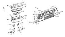
- FIG. 1shows an exploded view of an electrical connector housing and an electrical connector in the form of a fuse, in accordance with one embodiment of the present invention
- FIG. 2shows a partial fragmentary assembled view of the electrical connector housing and fuse shown in FIG. 1 ;
- FIG. 3shows an isometric view of the electrical connector housing and fuse shown in FIG. 1 , with a first housing portion unlatched from a second housing portion;
- FIG. 4shows an isometric view of the electrical connector housing shown in FIG. 3 , with the first and second housing portions in a first mating position;
- FIG. 5Ashows a partial fragmentary exploded view of a fuse holder cover and fuse in accordance with another embodiment of the present invention
- FIG. 5Bshows a partial fragmentary assembled view of the fuse holder cover and fuse shown in FIG. 5A ;
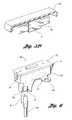
- FIG. 6shows an isometric view of an electrical connector housing in accordance with another embodiment of the present invention.
- FIG. 7Ashows an isometric view of a female electrical terminal in accordance with embodiments of the invention.
- FIG. 7Bshows an exploded view of the female terminal shown in FIG. 7A ;
- FIG. 8Ashows an isometric view of a female electrical terminal in accordance with embodiments of the invention.
- FIG. 8Bshows an exploded view of the female terminal shown in FIG. 8A ;
- FIG. 9shows a fuse body in accordance with embodiments of the invention.
- FIG. 1shows an exploded view of an electrical connector housing, or fuse holder 10 , in accordance with one embodiment of the present invention.
- the fuse holder 10includes a first housing portion, or base 12 , which defines an interior space 14 .
- the fuse holder 10also includes a second housing portion, or cover 16 , and a seal 18 configured to be disposed between the base 12 and the cover 16 .
- the fuse holder 10also includes first and second electrically conducting elements, or terminals 20 , 22 .
- the terminals 20 , 22are male terminals, which respectively include first connector portions 24 , 26 .
- first connector portions 24 , 26are configured to cooperate with an electrical connector, such as a fuse 28 , to electrically connect the first and second terminals 20 , 22 .
- first and second electrical attachment features, or female terminals 30 , 32are shown in FIG. 1 .
- the female terminals 30 , 32are spring terminals configured to be disposed on the first connector portions 24 , 26 of the male terminals 20 , 22 ; they are also configured to receive the fuse 28 , which in the embodiment shown in FIG. 1 , is a male connector.
- FIG. 2shows a partial fragmentary view of the fuse holder 10 with all of the components assembled.
- One method of producing the fuse holder 10is to mold the base 12 from a polymeric or composite material. In automotive applications, where heat resistance is required, a polyamide with a 30% glass field has been shown to be effective. Of course, other materials may be used, including other polymers and composites, depending on the particular application.
- the terminals 20 , 22are integrally formed with the base 12 . This can be done by a technique commonly known as “overmolding”. Integrally molding the terminals 20 , 22 with the base 12 , provides a robust method of attachment, and isolates the fuse 28 from outside stresses, thereby providing a built-in strain relief.
- the use of the separate female terminals 30 , 32which are installed after the base 12 is molded, helps to facilitate the overmolding process by reducing the complexity of the setup and/or tooling.
- the first contact portions 24 , 26must be free of the material used to mold the base 12 —e.g., the polyamide/glass material.
- Male terminals, such as the terminals 20 , 22are easier to shield from the molded material, and the female terminals 30 , 32 are quickly and easily applied to the first contact portions 24 , 26 after the base 12 is molded.
- each of the male terminals 20 , 22also includes a second connector portion 34 , 36 , respectively.
- the second connector portions 34 , 36are each configured to retain a wire 38 , 40 .
- neither of the wires 38 , 40has a terminated end; rather, the end of each wire 38 , 40 is crimped in a respective connector portion 34 , 36 .
- the second connector portionscan be configured in virtually any shape effective to provide a connection point to another electrically conducting element, such as, a crimp terminal, a welding interface, or an eyelet or ring terminal. In the embodiment shown in FIG.
- the second connector portions 34 , 36are oriented generally perpendicular to their respective first connector portions 24 , 26 . This may further help to reduce stress and/or strain on the fuse 28 , because more of the terminals 20 , 22 are molded into the base 12 .
- the base 12 and the cover 16cooperate with each other in a first mating position which is maintained by a latch mechanism 42 on one side, and a hinge mechanism 44 on the other.
- the latch mechanism 42includes an attachment structure 46 and a receiving structure 48 (see FIG. 1 ) respectively molded with the base 12 and the cover 16 .
- the receiving structure 48is configured to receive the attachment structure 46 to help secure the base 12 to the cover 16 .
- the hinge mechanism 44includes first and second portions 49 , 51 (see FIG. 1 ) also respectively molded with the base 12 and the cover 16 .
- the hinge mechanism 44allows the base 12 and the cover 16 to pivot relative to each other, which is best illustrated in FIG. 3 .
- the cover 16includes a retaining structure 52 which includes first and second portions, or retaining elements 54 , 56 .
- the first retaining element 54includes a lip 58 under which one end of the fuse 28 is placed. The other end of the fuse 28 is snapped into the second retaining element 56 , which in the embodiment shown in FIG. 3 , is configured as a clip.
- the cover 16may be conveniently molded of an appropriate material, such as a heat resistant polymer or composite. This allows the retaining structure 52 to be integrally molded with the cover 16 , thereby eliminating the need for a separate assembly operation.
- the cover 16can be pivoted into the first mating position with the base 12 .
- This movementis illustrated by the directional arrow shown in FIG. 3 .
- the fuse 28will be sequentially connected to the two terminals 20 , 22 in the base 12 as the base 12 and the cover 16 are brought together into the first mating position. Specifically, a first portion 60 of the fuse 28 will be received by the female terminal 32 in the base 12 . After contact is made, a second portion 62 of the fuse 28 will be received by the other female terminal 30 .
- the fuse 28may be connected to the female terminals 30 , 32 one at a time, which reduces the insertion force necessary to connect the fuse 28 with the terminals 30 , 32 .
- the retaining structure 52is configured to hold the fuse 28 to allow it to be automatically connected to the terminals 30 , 32 when the base 12 and the cover 16 are pivoted together into the first mating position. Similarly, the retaining structure 52 will retain the fuse 28 when the base 12 and the cover 16 are pivoted out of the first mating position. Thus, pivoting the cover 16 away from the base 12 will automatically disconnect the fuse 28 from the terminal 30 , and then from the terminal 32 , in reverse order of their connection.
- the configuration of the fuse holder 10eliminates the requirement for insulation on a fuse that would otherwise be used to grip the fuse as it is inserted into an electrical circuit.
- the fuse 28is an all metal fuse, devoid of insulation.
- the cover 16can be molded from a material which not only provides heat resistance for automotive environments, but also provides electrical insulation to isolate the fuse 28 from an operator opening or closing the housing 10 .
- the cover 16may be reusable, in which case a new fuse is secured within the retaining structure 52 after the fuse 28 is removed.
- a number of covers, such as the cover 16can be pre-loaded with fuses so that replacement of a fuse merely requires replacement of the cover—the fuse need never be removed from the retaining structure.
- the base 12 and the cover 16are shown in the first mating position. When they are in the first mating position, the base 12 and the cover 16 provide a substantially sealed enclosure for the fuse 28 and the associated electrical terminals 20 , 22 and 30 , 32 . Also shown in FIG. 4 , the cover 16 includes a protrusion 62 molded therein to accommodate a protruding portion 66 of the fuse 28 (see also FIG. 3 ). Although the housing portions 12 , 16 do not need to be molded, or made from a polymeric material, it does provide a convenient method for producing a fuse holder, such as the fuse holder 10 . Not only can the geometric configuration of the fuse holder 10 be modified to accommodate different styles of fuses and/or electrical terminals, but an appropriate choice of a polymeric material effectively insulates the electrical connectors, and eliminates the need to use a fuse having its own insulation.
- FIG. 5Ashows a portion of a second housing portion, or fuse holder cover 65 , having a retaining structure that is different from the one shown in FIG. 3 .
- the cover 65is shown without latch and hinge mechanisms, such as the latch and hinge mechanisms 42 , 44 shown in FIG. 2 , it is understood that it may contain these or other attachment features so that it can cooperate with a base portion of a fuse holder.
- Integrally molded with the cover 65is a first portion 67 of a retaining structure configured to carry a fuse 69 .
- a second portion 71 of the retaining structureSeparate from the first portion 67 is a second portion 71 of the retaining structure.
- the second portion 71is separate from the cover 65 , it could be molded substantially simultaneously with the cover 65 , for example, in a separate cavity of the same mold tool.
- the first and second portions 67 , 71 of the retaining structurecooperate to capture the fuse 69 between them.
- One convenient method of attaching the first and second portions 67 , 71 togetheris to sonic weld them to each other. Alternatively, they could be heat-staked, or an adhesive could be used, depending on the particular application.
- one convenient method of using a fuse holder in accordance with the present inventionis to secure fuses into a number of respective fuse holder covers, such as the cover 65 , and when a fuse needs replacing, the entire cover, including the fuse, is replaced.
- FIG. 6shows an electrical connector housing, or fuse holder 66 in accordance with another embodiment of the present invention. Similar to the fuse holder 10 , the fuse holder 66 includes first and second housing portions 68 , 70 which cooperate with each other in a first mating position, as shown in FIG. 5 . A latch mechanism 72 and a hinge mechanism 74 allow the first and second housing portions 68 , 70 to be pivoted relative to each other, and securely latched in the first mating position. Although not visible in FIG. 6 , first and second terminals 76 , 78 each have first connector portions which are configured to receive female terminals to facilitate connection to a fuse, such as the fuse 28 .
- the terminals 76 , 78have markedly different second connector portions 80 , 82 , respectively.
- the second connector portion 80 of the first terminal 76is a thick male terminal that is configured to receive a fork terminal 84 , which may be attached to an electrically conducting element, such as a wire 86 .
- the second connector portion 82 of the second terminal 78is a ring terminal, which facilitates secure attachment to another electrically conducting element (not shown) through the use of a bolt, or other stud-type fastener. It is worth noting that the embodiment shown in FIG. 6 represents just one variation of many different varieties of terminals which may be used with a fuse holder, in accordance with the present invention.
- FIG. 7Ashows a female electrical terminal 88 .
- the female terminal 88can be used as an attachment structure, such as the female terminals 30 , 32 shown in FIG. 1 .
- the female terminal 88includes a terminal receptor 90 , and a clamp-like member 92 .
- the terminal receptor 90can be made, for example, from a single piece of stamped metal, such as copper.
- the terminal receptor 90includes a first set of terminal legs 94 , which includes first and second opposing legs 96 , 98 and third and fourth opposing legs 100 , 102 .
- Each of the legs 96 - 102are resilient for maintaining a compressive force on a male electrical terminal blade, such as the male terminals 20 , 22 shown in FIG. 1 .
- the clamp-like member 92is configured as a substantially U-shaped body having first and second end portions 104 , 106 .
- the first and second end portions 104 , 106may have an arc-shaped cross section furthering the nesting relationship between the first end portion 104 and the first and third legs 96 , 100 , and the second end portion 106 and the second and fourth legs 98 , 102 .
- the clamp-like member 92may be made from a material having low relaxation properties at elevated temperatures, for example, 301 stainless steel. Because of this property, and the compressive force that the clamp-like member 92 can apply to the legs 96 - 102 of the female terminal 88 , the terminal receptor 90 can be made from a highly conductive material, such as C151 copper. Without the use of the clamp-like member 92 , higher temperature applications—such as high power applications where more than 70 amperes (A) of current may be present—may require the terminal receptor 90 to be made from a copper alloy having better mechanical properties at higher temperatures, but poorer conductivity than the more pure copper material.
- Aamperes
- the female terminal 88may have a width (W) of a little over 6 millimeters (mm). A terminal of this size, when used with the clamp-like member 92 , may be used in applications requiring up to 130 A. Where higher current applications are contemplated, a terminal, such as the female terminal 88 shown in FIGS. 7A and 7B , can be made wider such as illustrated in FIGS. 8A and 8B . In FIGS. 8A and 8B , a female terminal 106 has a width (W) of approximately 14.5 mm.
- the female terminal 106includes a terminal receptor 108 and four sets of opposing terminal legs 110 , 112 , 114 , 116 .
- the female terminal 106also includes two clamp-like structures 118 , 120 , each configured to cooperate with two sets of the legs 110 - 116 to apply a compressive force to a male terminal that will be inserted therebetween.
- FIG. 8Bshows an exploded view of the terminal 106 , illustrating the clamp-like members 118 , 120 detached from the legs 110 - 116 .
- FIG. 9shows the female terminal 106 , in conjunction with another similarly configured terminal 106 ′ being used in conjunction with a fuse or fuse element 122 , and forming a fuse body 124 .
- the fuse element 122electrically connects the female terminals 106 , 106 ′, and is therefore an electrical connector, such as element 28 , shown in FIG. 1 .
- the fuse element 122is welded to the female terminals 106 , 106 ′, thereby forming an assembly that can be inserted into the lid of a housing, such as the cover 16 shown in FIG. 1 .
- Other types of attachmentsare also contemplated, for example, depending on the particular application, spot welding or adhesive connections may be used.
- a fuse elementcan be integrally formed with terminal receptors.
- Such a configurationis described in U.S. Patent Application Publication No. 2009/0085712, entitled “High Power Case Fuse” and published on 2 Apr. 2009, which is hereby incorporated herein by reference.
- the fuse bodysuch as the fuse body 124
- separate attachment structuressuch as terminals 30 , 32 are not required, as the female terminals 106 , 106 ′ will directly mate with the first connector portions 24 , 26 of the male terminals 20 , 22 .
- the smaller width terminal 88shown in FIGS. 7A and 7B can be used in applications at least up to 130 A.
- the “double-width” terminals 106 , 106 ′can be used in applications up to at least 500 A. In these applications it may be particularly important to utilize an electrical connector housing, such as illustrated in FIGS. 1-6 so that technicians are isolated from the conducting elements when contact is made.
- the high power terminals used in the present invention, such as the terminals 88 , 106provide for fast electrical connections that do not require bolt-on attachments which may otherwise be required for such high power applications.
Landscapes
- Fuses (AREA)
- Details Of Connecting Devices For Male And Female Coupling (AREA)
Abstract
Description
Claims (14)
Priority Applications (3)
| Application Number | Priority Date | Filing Date | Title |
|---|---|---|---|
| US12/509,898US8242874B2 (en) | 2005-08-23 | 2009-07-27 | Electrical connector housing |
| CN201010240487.2ACN101969013B (en) | 2009-07-27 | 2010-07-27 | Electrical connector housing |
| DE102010038467ADE102010038467A1 (en) | 2009-07-27 | 2010-07-27 | Electrical connector housing i.e. fuse holder, for holding high power electrical fuse, has connector portions receiving wire to provide in-line connection of wire when connector is positioned to electrically connect conducting elements |
Applications Claiming Priority (2)
| Application Number | Priority Date | Filing Date | Title |
|---|---|---|---|
| US11/161,931US20070046417A1 (en) | 2005-08-23 | 2005-08-23 | Electrical connector housing and method of producing same |
| US12/509,898US8242874B2 (en) | 2005-08-23 | 2009-07-27 | Electrical connector housing |
Related Parent Applications (1)
| Application Number | Title | Priority Date | Filing Date |
|---|---|---|---|
| US11/161,931Continuation-In-PartUS20070046417A1 (en) | 2005-08-23 | 2005-08-23 | Electrical connector housing and method of producing same |
Publications (2)
| Publication Number | Publication Date |
|---|---|
| US20090309689A1 US20090309689A1 (en) | 2009-12-17 |
| US8242874B2true US8242874B2 (en) | 2012-08-14 |
Family
ID=43430326
Family Applications (1)
| Application Number | Title | Priority Date | Filing Date |
|---|---|---|---|
| US12/509,898Expired - Fee RelatedUS8242874B2 (en) | 2005-08-23 | 2009-07-27 | Electrical connector housing |
Country Status (3)
| Country | Link |
|---|---|
| US (1) | US8242874B2 (en) |
| CN (1) | CN101969013B (en) |
| DE (1) | DE102010038467A1 (en) |
Cited By (20)
| Publication number | Priority date | Publication date | Assignee | Title |
|---|---|---|---|---|
| US20120019345A1 (en)* | 2010-07-21 | 2012-01-26 | Von Zur Muehlen Patrick A | Compact modular fuse block with integrated fuse clearance |
| US8419475B2 (en)* | 2011-07-19 | 2013-04-16 | Cooper Technologies Company | Modular open fuseholder with multi-stage positionable cover |
| US8475220B2 (en) | 2010-11-24 | 2013-07-02 | Lear Corporation | Power terminal |
| US20130257580A1 (en)* | 2012-03-27 | 2013-10-03 | Littelfuse, Inc. | Fuse end cap with crimpable terminal |
| US8608519B1 (en)* | 2012-05-24 | 2013-12-17 | Cooper Technologies Company | Quick lock conductor receiver |
| US20140162485A1 (en)* | 2012-12-06 | 2014-06-12 | Phoenix Contact Development & Manufacturing, Inc. | Modular Electric Power Distribution System |
| US20180061606A1 (en)* | 2014-06-30 | 2018-03-01 | Cooper Technologies Company | Pluggable touch-safe fuse module with built-in removal handle |
| US20180076574A1 (en)* | 2016-09-14 | 2018-03-15 | Tyco Electronics (Shanghai) Co. Ltd. | Electric Connection Assembly |
| US10320129B2 (en)* | 2015-03-12 | 2019-06-11 | Aees, Inc. | Low profile terminal assembly |
| US10693252B2 (en) | 2016-09-30 | 2020-06-23 | Riddell, Inc. | Electrical connector assembly for high-power applications |
| US10826280B2 (en)* | 2016-07-01 | 2020-11-03 | Sumitomo Wiring Systems, Ltd. | Electrical connection box with dark current circuit connection/disconnection structure |
| US10916897B1 (en) | 2020-02-13 | 2021-02-09 | Aees Inc. | Battery mounted fuse holder |
| US11398696B2 (en) | 2018-06-07 | 2022-07-26 | Eaton Intelligent Power Limited | Electrical connector assembly with internal spring component |
| US11411336B2 (en) | 2018-02-26 | 2022-08-09 | Eaton Intelligent Power Limited | Spring-actuated electrical connector for high-power applications |
| US11721927B2 (en) | 2019-09-09 | 2023-08-08 | Royal Precision Products Llc | Connector recording system with readable and recordable indicia |
| US11721942B2 (en) | 2019-09-09 | 2023-08-08 | Eaton Intelligent Power Limited | Connector system for a component in a power management system in a motor vehicle |
| US11929572B2 (en) | 2020-07-29 | 2024-03-12 | Eaton Intelligent Power Limited | Connector system including an interlock system |
| US11990720B2 (en) | 2019-01-21 | 2024-05-21 | Eaton Intelligent Power Limited | Power distribution assembly with boltless busbar system |
| US12015376B2 (en) | 2014-09-09 | 2024-06-18 | Shoals Technologies Group, Llc | Lead assembly for connecting solar panel arrays to inverter |
| US12237605B2 (en) | 2019-01-15 | 2025-02-25 | Eaton Intelligent Power Limited | Shielded electrical connector system with internal spring component |
Families Citing this family (29)
| Publication number | Priority date | Publication date | Assignee | Title |
|---|---|---|---|---|
| DE102008022051A1 (en)* | 2008-05-03 | 2009-11-19 | Lumberg Connect Gmbh | Junction box for a solar module |
| DE102008062034B4 (en)* | 2008-12-12 | 2010-08-12 | Tyco Electronics Amp Gmbh | Connecting device for connection to a solar module and solar module with such a connection device |
| US8366497B2 (en) | 2009-06-17 | 2013-02-05 | Lear Corporation | Power terminal |
| DE102011122944B3 (en) | 2010-06-10 | 2023-10-26 | Lear Corporation | Connection socket |
| US8342885B2 (en) | 2011-05-09 | 2013-01-01 | Yazaki North America, Inc. | Serviceable inline AC fuse holder |
| USD671079S1 (en) | 2011-05-09 | 2012-11-20 | Yazaki North America, Inc. | Serviceable inline AC fuse holder |
| US9196445B2 (en)* | 2011-07-05 | 2015-11-24 | Cooper Technologies Company | Electric fuse with torque restricting terminals |
| US9202656B2 (en) | 2011-10-27 | 2015-12-01 | Littelfuse, Inc. | Fuse with cavity block |
| EP3142137B1 (en)* | 2011-10-27 | 2018-12-12 | Littelfuse, Inc. | Fuse with insulated plugs |
| US9558905B2 (en)* | 2011-10-27 | 2017-01-31 | Littelfuse, Inc. | Fuse with insulated plugs |
| CN102983046B (en)* | 2012-11-21 | 2015-08-19 | 宁波市鄞州永林电子电器有限公司 | A kind of AUTOMOTIVE RELAY of sealed type band safeties |
| US9666968B2 (en) | 2013-01-17 | 2017-05-30 | Lear Corporation | Electrical busbar, electrical connector assembly and power converter |
| CN103617934B (en)* | 2013-11-29 | 2016-03-09 | 贵州航天电器股份有限公司 | A kind of fuse connector connected for on-site cable |
| CN103779146B (en)* | 2014-01-08 | 2016-08-17 | 苏州工业园区驿力机车科技股份有限公司 | Car insurance box device |
| DE102015204295A1 (en)* | 2015-03-10 | 2016-09-15 | Robert Bosch Gmbh | fuse holder |
| US10039173B2 (en)* | 2016-07-13 | 2018-07-31 | Abl Ip Holding Llc | Building line power adapter and a device incorporating the same |
| US10325747B2 (en)* | 2017-01-31 | 2019-06-18 | Littelfuse, Inc. | In-line high current fuse holder assembly |
| CN208508146U (en) | 2018-08-15 | 2019-02-15 | 宁德时代新能源科技股份有限公司 | Multifunctional high pressure connector and battery product |
| CN208690601U (en)* | 2018-08-15 | 2019-04-02 | 宁德时代新能源科技股份有限公司 | Conductive connection structure, multifunctional high voltage connector and battery products |
| CN208690572U (en)* | 2018-08-15 | 2019-04-02 | 宁德时代新能源科技股份有限公司 | Plug terminals, multifunctional high voltage connectors and battery products |
| CN208955294U (en)* | 2018-11-08 | 2019-06-07 | 宁德时代新能源科技股份有限公司 | Multifunctional high pressure connector |
| US10763629B1 (en)* | 2019-08-12 | 2020-09-01 | Lear Corporation | Integrated assembly of an electrical conductor, a fuse and a connector |
| JP7433811B2 (en)* | 2019-08-23 | 2024-02-20 | デクセリアルズ株式会社 | Fuse elements, fuse elements and protection elements |
| JP7265461B2 (en)* | 2019-09-26 | 2023-04-26 | 住友電装株式会社 | Power supply device and branch connector device |
| CN112086222B (en)* | 2020-08-25 | 2021-12-14 | 南京鑫瀚瑞电子有限公司 | Wire with fuse and fuse mounting method |
| JP7016570B1 (en)* | 2021-03-05 | 2022-02-07 | エス・オー・シー株式会社 | fuse |
| USD1034405S1 (en)* | 2021-09-02 | 2024-07-09 | Wago Verwaltungsgesellschaft Mbh | Inline connector |
| CN116013747A (en)* | 2021-10-22 | 2023-04-25 | 苏州力特奥维斯保险丝有限公司 | Sealed inline fuse module |
| FR3150638A1 (en)* | 2023-06-28 | 2025-01-03 | Psa Automobiles Sa | FUSE BOX WITH IPXXB PROTECTION PLATE FOR MOTOR VEHICLE |
Citations (53)
| Publication number | Priority date | Publication date | Assignee | Title |
|---|---|---|---|---|
| US348048A (en) | 1886-08-24 | Charles g | ||
| US743471A (en) | 1903-01-12 | 1903-11-10 | D & W Fuse Company | Fuse casing and switch. |
| US945017A (en) | 1907-04-29 | 1910-01-04 | Pratt Johns Co | Fuse-box. |
| US1158535A (en) | 1914-12-22 | 1915-11-02 | Thomas E Murray | Cut-out switch. |
| US1857442A (en) | 1929-11-14 | 1932-05-10 | Line Material Co | Fuse box structure |
| US1966716A (en)* | 1932-01-25 | 1934-07-17 | Frank Adam Electric Co | Circuit interrupting and protecting apparatus |
| US1993866A (en) | 1931-06-01 | 1935-03-12 | Line Material Co | Fuse |
| US2001432A (en) | 1933-03-11 | 1935-05-14 | Products Prot Corp | Circuit controlling and indicating device |
| US2011391A (en) | 1928-05-12 | 1935-08-13 | Gen Electric | Cut-out |
| US2011543A (en) | 1931-11-10 | 1935-08-13 | Porcelain Products Inc | Transformer cut-out |
| US2016099A (en) | 1928-06-16 | 1935-10-01 | Westinghouse Electric & Mfg Co | Fuse cut-out |
| US2186813A (en)* | 1936-06-29 | 1940-01-09 | Frank Adam Electric Co | Circuit interrupting and protecting device |
| USRE22266E (en) | 1943-02-16 | Circuit interrupting and protecting | ||
| US2700712A (en) | 1953-07-01 | 1955-01-25 | Leonard E Stinson | Line cutout clamp |
| US2907849A (en) | 1956-12-20 | 1959-10-06 | Murray Mfg Corp | Pullout switch |
| US3030474A (en)* | 1959-02-20 | 1962-04-17 | Ite Circuit Breaker Ltd | Removable cover for current limiting fuse housing |
| US3202788A (en) | 1962-03-22 | 1965-08-24 | Square D Co | Cartridge fuse pull-out switch |
| US3358100A (en)* | 1966-03-03 | 1967-12-12 | Arrow Hart & Hegeman Electric | Fused puller switch with fuses which can be removed only when the fused section is first removed |
| US3699500A (en) | 1969-12-19 | 1972-10-17 | John J Borzoni | Fuse holder assembly |
| US4178061A (en) | 1977-02-15 | 1979-12-11 | Ahroni Joseph M | Fused electrical plug |
| GB2128042A (en) | 1982-09-28 | 1984-04-18 | Dorman Smith Fuses | Electric cartridge fuselink carrier |
| DE8601549U1 (en) | 1985-01-22 | 1986-03-27 | Cambridge Electronic Industries p.l.c., Cambridge | Fuse holder |
| US4613195A (en) | 1985-03-14 | 1986-09-23 | Cooper Industries, Inc. | Cartridge fuse terminal adapter |
| US4752243A (en) | 1987-06-02 | 1988-06-21 | Noma Inc. | Fuse plug |
| US4997394A (en) | 1990-05-18 | 1991-03-05 | Triplex Manufacturing Co. | Water resistant fuse holder |
| US5145414A (en) | 1989-12-11 | 1992-09-08 | Yazaki Corporation | Fuse holder construction |
| US5221217A (en) | 1989-12-11 | 1993-06-22 | Ryuetsu Oikawa | Fuse holder construction |
| US5748068A (en) | 1995-12-20 | 1998-05-05 | Yazaki Corporation | Fuse box |
| US5752856A (en) | 1996-07-30 | 1998-05-19 | The Whitaker Corporation | Sealed fuse connector |
| US5820413A (en) | 1995-11-27 | 1998-10-13 | Yazaki Corporation | Fuse box |
| US5841337A (en)* | 1997-01-17 | 1998-11-24 | Cooper Technologies Company | Touch safe fuse module and holder |
| US5880665A (en) | 1998-05-22 | 1999-03-09 | The Whitaker Corporation | Fuse holder |
| US5906508A (en)* | 1996-12-18 | 1999-05-25 | Thomas & Betts Corporation | Electrical disconnect for use with an appliance |
| US5973418A (en) | 1998-05-05 | 1999-10-26 | Cooper Technologies Company | Pull-out high current switch |
| US6054915A (en)* | 1998-02-17 | 2000-04-25 | Cooper Industries, Inc. | Compact touchsafe fuseholder with removable fuse carrier |
| DE10009605A1 (en) | 1999-03-01 | 2000-10-19 | Yazaki Corp | Power supply interrupting device for electric vehicles, includes detachable fuse box inserted into stationary box such that fuse terminals contact elastic connection of load and power supply side bus bars |
| US6233160B1 (en) | 1999-11-12 | 2001-05-15 | James P. Shockley | Water/vapor proof marine fuse box |
| US6333845B1 (en)* | 1999-01-27 | 2001-12-25 | Yazaki Corporation | Power-supply breaker apparatus |
| US6366449B1 (en)* | 1999-05-06 | 2002-04-02 | Yazaki Corporation | Power supply shut-off apparatus |
| US20020047770A1 (en) | 2000-10-24 | 2002-04-25 | Scoggin B. Heath | Compact fused disconnect switch |
| US6587028B2 (en) | 2000-07-07 | 2003-07-01 | Cooper Technologies Company | Fused disconnect switch |
| US6650222B2 (en)* | 2000-12-07 | 2003-11-18 | Cooper Technologies Company | Modular fuseholder |
| US6696969B2 (en) | 2000-06-30 | 2004-02-24 | Cooper Technologies, Inc. | Compact fused disconnect switch |
| US6717505B1 (en) | 1999-11-23 | 2004-04-06 | Klaus Bruchmann | Circuit protection unit with fuse carrier and fuse status indicator |
| US6727797B1 (en) | 1999-07-22 | 2004-04-27 | Klaus Bruchmann | Fuse combination unit with maintained locking |
| US20040100786A1 (en) | 2002-11-26 | 2004-05-27 | Yong-Qing Hong | Fuse box |
| US6794979B2 (en) | 2002-04-26 | 2004-09-21 | General Electric Company | Fuse holder assembly |
| US6850421B2 (en) | 2002-04-01 | 2005-02-01 | Tyco Electronics Corporation | Fuse relay box apparatus, methods and articles of manufacture |
| US6853289B2 (en)* | 2000-10-24 | 2005-02-08 | Cooper Technologies Company | Fuse handle for fused disconnect switch |
| US7750789B2 (en)* | 2007-05-18 | 2010-07-06 | Kostal Kontakt Systeme Gmbh | High-power breaker switch for a vehicle |
| US7893809B2 (en)* | 2009-02-19 | 2011-02-22 | Tyco Electronics Corporation | Service disconnect assembly for a high voltage electronic module |
| US7982578B2 (en)* | 2008-04-01 | 2011-07-19 | Wöhner GmbH & Co. KG, Elektrotechnische Systeme | Switch disconnector |
| US8026786B2 (en)* | 2008-07-25 | 2011-09-27 | Cooper Technologies Company | Touch safe fuse module with improved wiring lugs |
Family Cites Families (10)
| Publication number | Priority date | Publication date | Assignee | Title |
|---|---|---|---|---|
| US4367279A (en)* | 1974-09-06 | 1983-01-04 | Eastman Kodak Company | Silver halide complexing agents of sulfones, nitriles, and onium salts |
| TW378213B (en)* | 1992-11-04 | 2000-01-01 | Shionogy Seiyaku Kk | Basophil-binding monoclonal antibody, method for separation of basophils, method for chemical mediator released from basophils, and testing method for release of basophil-derived chemical mediators |
| US5491071A (en)* | 1993-08-03 | 1996-02-13 | Abbott Laboratories | Reagents and methods for the detection and quantification of testosterone in fluid samples |
| US5858648A (en)* | 1996-11-04 | 1999-01-12 | Sienna Biotech, Inc. | Assays using reference microparticles |
| US5981296A (en)* | 1997-02-18 | 1999-11-09 | Dade Behring Inc. | Stabilization of particle reagents |
| DE19857897A1 (en)* | 1998-12-15 | 2000-06-21 | Basf Ag | Process for the preparation of aqueous polymer dispersions |
| EP1797576A4 (en)* | 2004-09-15 | 2008-12-10 | Littelfuse Inc | High voltage/high current fuse |
| JP4706613B2 (en)* | 2006-03-24 | 2011-06-22 | 住友電装株式会社 | Slow blow fuse fuse element, slow blow fuse and electrical junction box |
| CN201041800Y (en)* | 2006-04-24 | 2008-03-26 | 东莞市太基电子有限公司 | Power circuit protection device |
| US7595715B2 (en) | 2007-09-27 | 2009-09-29 | Lear Corporation | High power case fuse |
- 2009
- 2009-07-27USUS12/509,898patent/US8242874B2/ennot_activeExpired - Fee Related
- 2010
- 2010-07-27DEDE102010038467Apatent/DE102010038467A1/ennot_activeWithdrawn
- 2010-07-27CNCN201010240487.2Apatent/CN101969013B/ennot_activeExpired - Fee Related
Patent Citations (54)
| Publication number | Priority date | Publication date | Assignee | Title |
|---|---|---|---|---|
| USRE22266E (en) | 1943-02-16 | Circuit interrupting and protecting | ||
| US348048A (en) | 1886-08-24 | Charles g | ||
| US743471A (en) | 1903-01-12 | 1903-11-10 | D & W Fuse Company | Fuse casing and switch. |
| US945017A (en) | 1907-04-29 | 1910-01-04 | Pratt Johns Co | Fuse-box. |
| US1158535A (en) | 1914-12-22 | 1915-11-02 | Thomas E Murray | Cut-out switch. |
| US2011391A (en) | 1928-05-12 | 1935-08-13 | Gen Electric | Cut-out |
| US2016099A (en) | 1928-06-16 | 1935-10-01 | Westinghouse Electric & Mfg Co | Fuse cut-out |
| US1857442A (en) | 1929-11-14 | 1932-05-10 | Line Material Co | Fuse box structure |
| US1993866A (en) | 1931-06-01 | 1935-03-12 | Line Material Co | Fuse |
| US2011543A (en) | 1931-11-10 | 1935-08-13 | Porcelain Products Inc | Transformer cut-out |
| US1966716A (en)* | 1932-01-25 | 1934-07-17 | Frank Adam Electric Co | Circuit interrupting and protecting apparatus |
| US2001432A (en) | 1933-03-11 | 1935-05-14 | Products Prot Corp | Circuit controlling and indicating device |
| US2186813A (en)* | 1936-06-29 | 1940-01-09 | Frank Adam Electric Co | Circuit interrupting and protecting device |
| US2700712A (en) | 1953-07-01 | 1955-01-25 | Leonard E Stinson | Line cutout clamp |
| US2907849A (en) | 1956-12-20 | 1959-10-06 | Murray Mfg Corp | Pullout switch |
| US3030474A (en)* | 1959-02-20 | 1962-04-17 | Ite Circuit Breaker Ltd | Removable cover for current limiting fuse housing |
| US3202788A (en) | 1962-03-22 | 1965-08-24 | Square D Co | Cartridge fuse pull-out switch |
| US3358100A (en)* | 1966-03-03 | 1967-12-12 | Arrow Hart & Hegeman Electric | Fused puller switch with fuses which can be removed only when the fused section is first removed |
| US3699500A (en) | 1969-12-19 | 1972-10-17 | John J Borzoni | Fuse holder assembly |
| US4178061A (en) | 1977-02-15 | 1979-12-11 | Ahroni Joseph M | Fused electrical plug |
| GB2128042A (en) | 1982-09-28 | 1984-04-18 | Dorman Smith Fuses | Electric cartridge fuselink carrier |
| DE8601549U1 (en) | 1985-01-22 | 1986-03-27 | Cambridge Electronic Industries p.l.c., Cambridge | Fuse holder |
| GB2170067A (en) | 1985-01-22 | 1986-07-23 | Cambridge Electronic Ind | Fuse holder |
| US4613195A (en) | 1985-03-14 | 1986-09-23 | Cooper Industries, Inc. | Cartridge fuse terminal adapter |
| US4752243A (en) | 1987-06-02 | 1988-06-21 | Noma Inc. | Fuse plug |
| US5221217A (en) | 1989-12-11 | 1993-06-22 | Ryuetsu Oikawa | Fuse holder construction |
| US5145414A (en) | 1989-12-11 | 1992-09-08 | Yazaki Corporation | Fuse holder construction |
| US4997394A (en) | 1990-05-18 | 1991-03-05 | Triplex Manufacturing Co. | Water resistant fuse holder |
| US5820413A (en) | 1995-11-27 | 1998-10-13 | Yazaki Corporation | Fuse box |
| US5748068A (en) | 1995-12-20 | 1998-05-05 | Yazaki Corporation | Fuse box |
| US5752856A (en) | 1996-07-30 | 1998-05-19 | The Whitaker Corporation | Sealed fuse connector |
| US5906508A (en)* | 1996-12-18 | 1999-05-25 | Thomas & Betts Corporation | Electrical disconnect for use with an appliance |
| US5841337A (en)* | 1997-01-17 | 1998-11-24 | Cooper Technologies Company | Touch safe fuse module and holder |
| US6054915A (en)* | 1998-02-17 | 2000-04-25 | Cooper Industries, Inc. | Compact touchsafe fuseholder with removable fuse carrier |
| US5973418A (en) | 1998-05-05 | 1999-10-26 | Cooper Technologies Company | Pull-out high current switch |
| US5880665A (en) | 1998-05-22 | 1999-03-09 | The Whitaker Corporation | Fuse holder |
| US6333845B1 (en)* | 1999-01-27 | 2001-12-25 | Yazaki Corporation | Power-supply breaker apparatus |
| DE10009605A1 (en) | 1999-03-01 | 2000-10-19 | Yazaki Corp | Power supply interrupting device for electric vehicles, includes detachable fuse box inserted into stationary box such that fuse terminals contact elastic connection of load and power supply side bus bars |
| US6366449B1 (en)* | 1999-05-06 | 2002-04-02 | Yazaki Corporation | Power supply shut-off apparatus |
| US6727797B1 (en) | 1999-07-22 | 2004-04-27 | Klaus Bruchmann | Fuse combination unit with maintained locking |
| US6233160B1 (en) | 1999-11-12 | 2001-05-15 | James P. Shockley | Water/vapor proof marine fuse box |
| US6717505B1 (en) | 1999-11-23 | 2004-04-06 | Klaus Bruchmann | Circuit protection unit with fuse carrier and fuse status indicator |
| US6696969B2 (en) | 2000-06-30 | 2004-02-24 | Cooper Technologies, Inc. | Compact fused disconnect switch |
| US6587028B2 (en) | 2000-07-07 | 2003-07-01 | Cooper Technologies Company | Fused disconnect switch |
| US20020047770A1 (en) | 2000-10-24 | 2002-04-25 | Scoggin B. Heath | Compact fused disconnect switch |
| US6853289B2 (en)* | 2000-10-24 | 2005-02-08 | Cooper Technologies Company | Fuse handle for fused disconnect switch |
| US6650222B2 (en)* | 2000-12-07 | 2003-11-18 | Cooper Technologies Company | Modular fuseholder |
| US6850421B2 (en) | 2002-04-01 | 2005-02-01 | Tyco Electronics Corporation | Fuse relay box apparatus, methods and articles of manufacture |
| US6794979B2 (en) | 2002-04-26 | 2004-09-21 | General Electric Company | Fuse holder assembly |
| US20040100786A1 (en) | 2002-11-26 | 2004-05-27 | Yong-Qing Hong | Fuse box |
| US7750789B2 (en)* | 2007-05-18 | 2010-07-06 | Kostal Kontakt Systeme Gmbh | High-power breaker switch for a vehicle |
| US7982578B2 (en)* | 2008-04-01 | 2011-07-19 | Wöhner GmbH & Co. KG, Elektrotechnische Systeme | Switch disconnector |
| US8026786B2 (en)* | 2008-07-25 | 2011-09-27 | Cooper Technologies Company | Touch safe fuse module with improved wiring lugs |
| US7893809B2 (en)* | 2009-02-19 | 2011-02-22 | Tyco Electronics Corporation | Service disconnect assembly for a high voltage electronic module |
Cited By (40)
| Publication number | Priority date | Publication date | Assignee | Title |
|---|---|---|---|---|
| US20120019345A1 (en)* | 2010-07-21 | 2012-01-26 | Von Zur Muehlen Patrick A | Compact modular fuse block with integrated fuse clearance |
| US10026580B2 (en)* | 2010-07-21 | 2018-07-17 | Eaton Intelligent Power Limited | Compact modular fuse block with integrated fuse clearance |
| US8475220B2 (en) | 2010-11-24 | 2013-07-02 | Lear Corporation | Power terminal |
| US8419475B2 (en)* | 2011-07-19 | 2013-04-16 | Cooper Technologies Company | Modular open fuseholder with multi-stage positionable cover |
| US20130109236A1 (en)* | 2011-07-19 | 2013-05-02 | Cooper Technologies Company | Modular open fuse holder with multi-stage positionable cover |
| US8715008B2 (en)* | 2011-07-19 | 2014-05-06 | Cooper Technologies Company | Modular open fuse holder with multi-stage positionable cover |
| US9564281B2 (en)* | 2012-03-27 | 2017-02-07 | Littelfuse, Inc. | Fuse end cap with crimpable terminal |
| US20130257580A1 (en)* | 2012-03-27 | 2013-10-03 | Littelfuse, Inc. | Fuse end cap with crimpable terminal |
| US8608519B1 (en)* | 2012-05-24 | 2013-12-17 | Cooper Technologies Company | Quick lock conductor receiver |
| US8777678B2 (en)* | 2012-05-24 | 2014-07-15 | Cooper Technologies Company | Quick lock conductor receiver |
| US8986030B2 (en)* | 2012-12-06 | 2015-03-24 | Phoenix Contact Development and Manufacturing, Inc. | Modular electric power distribution system |
| US20140162485A1 (en)* | 2012-12-06 | 2014-06-12 | Phoenix Contact Development & Manufacturing, Inc. | Modular Electric Power Distribution System |
| US20180061606A1 (en)* | 2014-06-30 | 2018-03-01 | Cooper Technologies Company | Pluggable touch-safe fuse module with built-in removal handle |
| US10586672B2 (en)* | 2014-06-30 | 2020-03-10 | Eaton Intelligent Power Limited | Pluggable touch-safe fuse module with built-in removal handle |
| US12407295B2 (en) | 2014-09-09 | 2025-09-02 | Shoals Technologies Group, Llc | Lead assembly for connecting solar panel arrays to inverter |
| US12015375B2 (en) | 2014-09-09 | 2024-06-18 | Shoals Technologies Group, Llc | Lead assembly for connecting solar panel arrays to inverter |
| US12015376B2 (en) | 2014-09-09 | 2024-06-18 | Shoals Technologies Group, Llc | Lead assembly for connecting solar panel arrays to inverter |
| US10320129B2 (en)* | 2015-03-12 | 2019-06-11 | Aees, Inc. | Low profile terminal assembly |
| US10826280B2 (en)* | 2016-07-01 | 2020-11-03 | Sumitomo Wiring Systems, Ltd. | Electrical connection box with dark current circuit connection/disconnection structure |
| US20180076574A1 (en)* | 2016-09-14 | 2018-03-15 | Tyco Electronics (Shanghai) Co. Ltd. | Electric Connection Assembly |
| US10404016B2 (en)* | 2016-09-14 | 2019-09-03 | Tyco Electronics (Shanghai) Co. Ltd. | Electric connection assembly |
| US11223150B2 (en) | 2016-09-30 | 2022-01-11 | Royal Precision Products, Llc | Spring-actuated electrical connector for high-power applications |
| US10693252B2 (en) | 2016-09-30 | 2020-06-23 | Riddell, Inc. | Electrical connector assembly for high-power applications |
| US11870175B2 (en) | 2016-09-30 | 2024-01-09 | Eaton Intelligent Power Limited | Spring-actuated electrical connector for high-power applications |
| US12308550B2 (en) | 2016-09-30 | 2025-05-20 | Eaton Intelligent Power Limited | Spring-actuated electrical connector for high-power applications |
| US11411336B2 (en) | 2018-02-26 | 2022-08-09 | Eaton Intelligent Power Limited | Spring-actuated electrical connector for high-power applications |
| US11721924B2 (en) | 2018-02-26 | 2023-08-08 | Royal Precision Products Llc | Spring-actuated electrical connector for high-power applications |
| US11476609B2 (en) | 2018-06-07 | 2022-10-18 | Eaton Intelligent Power Limited | Electrical connector system with internal spring component and applications thereof |
| US11715900B2 (en) | 2018-06-07 | 2023-08-01 | Royal Precision Products Llc | Electrical connector system with internal spring component and applications thereof |
| US11715899B2 (en) | 2018-06-07 | 2023-08-01 | Royal Precision Products Llc | Electrical connector assembly with internal spring component |
| US11398696B2 (en) | 2018-06-07 | 2022-07-26 | Eaton Intelligent Power Limited | Electrical connector assembly with internal spring component |
| US12237605B2 (en) | 2019-01-15 | 2025-02-25 | Eaton Intelligent Power Limited | Shielded electrical connector system with internal spring component |
| US12381338B2 (en) | 2019-01-21 | 2025-08-05 | Eaton Intelligent Power Limited | Power distribution assembly with boltless busbar system |
| US11990720B2 (en) | 2019-01-21 | 2024-05-21 | Eaton Intelligent Power Limited | Power distribution assembly with boltless busbar system |
| US12132286B2 (en) | 2019-09-09 | 2024-10-29 | Eaton Intelligent Power Limited | Connector system for a component in a power management system in a motor vehicle |
| US12237610B2 (en) | 2019-09-09 | 2025-02-25 | Eaton Intelligent Power Limited | Connector recording system with readable and recordable indicia |
| US11721942B2 (en) | 2019-09-09 | 2023-08-08 | Eaton Intelligent Power Limited | Connector system for a component in a power management system in a motor vehicle |
| US11721927B2 (en) | 2019-09-09 | 2023-08-08 | Royal Precision Products Llc | Connector recording system with readable and recordable indicia |
| US10916897B1 (en) | 2020-02-13 | 2021-02-09 | Aees Inc. | Battery mounted fuse holder |
| US11929572B2 (en) | 2020-07-29 | 2024-03-12 | Eaton Intelligent Power Limited | Connector system including an interlock system |
Also Published As
| Publication number | Publication date |
|---|---|
| DE102010038467A1 (en) | 2011-02-10 |
| CN101969013B (en) | 2014-03-12 |
| CN101969013A (en) | 2011-02-09 |
| US20090309689A1 (en) | 2009-12-17 |
Similar Documents
| Publication | Publication Date | Title |
|---|---|---|
| US8242874B2 (en) | Electrical connector housing | |
| US7892050B2 (en) | High power fuse terminal with scalability | |
| US4842534A (en) | Fuse/bus bar assembly | |
| EP2145344B1 (en) | Devices, systems, and methods for coupling electrical conductors | |
| US7530843B1 (en) | Sealed electrical terminal | |
| US7503800B2 (en) | Meter jaw assembly | |
| EP3376598A1 (en) | A contact carrier, electrical contact unit and a method of producing a ready-made cable | |
| KR970001383B1 (en) | Spring clip electrical connector | |
| US10923846B1 (en) | Modular high performance contact element | |
| JP2003037920A (en) | Electrical connection box | |
| US11139600B1 (en) | High performance contact element | |
| CN1957434B (en) | Blade type fuse for automobile | |
| US9190784B1 (en) | High performance contact element | |
| US10276337B2 (en) | Fuses with integrated metals | |
| JP4879268B2 (en) | Busbar and connector | |
| US20070046417A1 (en) | Electrical connector housing and method of producing same | |
| US9543669B2 (en) | Supported termination | |
| KR20180045216A (en) | Connector | |
| US20230344175A1 (en) | Grounding device, grounding unit, contact insert and electrical plug connector, and method for producing a contact insert | |
| CN105684119B (en) | For the fuse used in distribution network | |
| CN115986498A (en) | Electrical plug connector for a bus bar | |
| WO2009005521A1 (en) | Fused power intercept | |
| KR102088887B1 (en) | Protector | |
| US20090001812A1 (en) | Fused Power Intercept | |
| EP3849021B1 (en) | Splice connector assembly and method of assembling a splice connector assembly |
Legal Events
| Date | Code | Title | Description |
|---|---|---|---|
| AS | Assignment | Owner name:LEAR CORPORATION, MICHIGAN Free format text:ASSIGNMENT OF ASSIGNORS INTEREST;ASSIGNORS:PAVLOVIC, SLOBADAN;MENZIES, DAVID;ZEIDAN, MOHAMAD;SIGNING DATES FROM 20090722 TO 20090825;REEL/FRAME:023157/0731 | |
| AS | Assignment | Owner name:JPMORGAN CHASE BANK, N.A., AS ADMINISTRATIVE AGENT Free format text:GRANT OF FIRST LIEN SECURITY INTEREST IN PATENT RIGHTS;ASSIGNOR:LEAR CORPORATION;REEL/FRAME:023519/0267 Effective date:20091109 Owner name:JPMORGAN CHASE BANK, N.A., AS ADMINISTRATIVE AGENT Free format text:GRANT OF SECOND LIEN SECURITY INTEREST IN PATENT RIGHTS;ASSIGNOR:LEAR CORPORATION;REEL/FRAME:023519/0626 Effective date:20091109 | |
| STCF | Information on status: patent grant | Free format text:PATENTED CASE | |
| CC | Certificate of correction | ||
| AS | Assignment | Owner name:JPMORGAN CAHSE BANK, N.A., AS AGENT, ILLINOIS Free format text:SECURITY INTEREST;ASSIGNOR:LEAR CORPORATION;REEL/FRAME:030076/0016 Effective date:20130130 Owner name:JPMORGAN CHASE BANK, N.A., AS AGENT, ILLINOIS Free format text:SECURITY INTEREST;ASSIGNOR:LEAR CORPORATION;REEL/FRAME:030076/0016 Effective date:20130130 | |
| AS | Assignment | Owner name:LEAR CORPORATION, MICHIGAN Free format text:RELEASE BY SECURED PARTY;ASSIGNOR:JPMORGAN CHASE BANK, N.A.;REEL/FRAME:032770/0843 Effective date:20100830 | |
| AS | Assignment | Owner name:LEAR CORPORATION, MICHIGAN Free format text:RELEASE BY SECURED PARTY;ASSIGNOR:JPMORGAN CHASE BANK, N.A., AS AGENT;REEL/FRAME:037701/0180 Effective date:20160104 Owner name:LEAR CORPORATION, MICHIGAN Free format text:RELEASE BY SECURED PARTY;ASSIGNOR:JPMORGAN CHASE BANK, N.A., AS AGENT;REEL/FRAME:037701/0251 Effective date:20160104 Owner name:LEAR CORPORATION, MICHIGAN Free format text:RELEASE BY SECURED PARTY;ASSIGNOR:JPMORGAN CHASE BANK, N.A., AS AGENT;REEL/FRAME:037701/0340 Effective date:20160104 | |
| AS | Assignment | Owner name:LEAR CORPORATION, MICHIGAN Free format text:RELEASE BY SECURED PARTY;ASSIGNOR:JPMORGAN CHASE BANK, N.A., AS AGENT;REEL/FRAME:037702/0911 Effective date:20160104 | |
| FPAY | Fee payment | Year of fee payment:4 | |
| FEPP | Fee payment procedure | Free format text:MAINTENANCE FEE REMINDER MAILED (ORIGINAL EVENT CODE: REM.); ENTITY STATUS OF PATENT OWNER: LARGE ENTITY | |
| LAPS | Lapse for failure to pay maintenance fees | Free format text:PATENT EXPIRED FOR FAILURE TO PAY MAINTENANCE FEES (ORIGINAL EVENT CODE: EXP.); ENTITY STATUS OF PATENT OWNER: LARGE ENTITY | |
| STCH | Information on status: patent discontinuation | Free format text:PATENT EXPIRED DUE TO NONPAYMENT OF MAINTENANCE FEES UNDER 37 CFR 1.362 | |
| FP | Lapsed due to failure to pay maintenance fee | Effective date:20200814 |