US8242710B2 - Driver device for a load and method of driving a load with such a driver device - Google Patents
Driver device for a load and method of driving a load with such a driver deviceDownload PDFInfo
- Publication number
- US8242710B2 US8242710B2US12/666,826US66682608AUS8242710B2US 8242710 B2US8242710 B2US 8242710B2US 66682608 AUS66682608 AUS 66682608AUS 8242710 B2US8242710 B2US 8242710B2
- Authority
- US
- United States
- Prior art keywords
- energy storage
- storage element
- load
- driver device
- voltage
- Prior art date
- Legal status (The legal status is an assumption and is not a legal conclusion. Google has not performed a legal analysis and makes no representation as to the accuracy of the status listed.)
- Active, expires
Links
- 238000000034methodMethods0.000titleabstractdescription12
- 238000004146energy storageMethods0.000claimsabstractdescription67
- 239000003990capacitorSubstances0.000claimsdescription6
- 230000003213activating effectEffects0.000description2
- 230000001419dependent effectEffects0.000description2
- 230000005669field effectEffects0.000description2
- 230000036962time dependentEffects0.000description2
- 230000004913activationEffects0.000description1
- 230000001934delayEffects0.000description1
- 238000010586diagramMethods0.000description1
- 238000005286illuminationMethods0.000description1
- 238000002955isolationMethods0.000description1
- 230000003071parasitic effectEffects0.000description1
- 230000007704transitionEffects0.000description1
Images

Classifications
- H—ELECTRICITY
- H05—ELECTRIC TECHNIQUES NOT OTHERWISE PROVIDED FOR
- H05B—ELECTRIC HEATING; ELECTRIC LIGHT SOURCES NOT OTHERWISE PROVIDED FOR; CIRCUIT ARRANGEMENTS FOR ELECTRIC LIGHT SOURCES, IN GENERAL
- H05B45/00—Circuit arrangements for operating light-emitting diodes [LED]
- H05B45/40—Details of LED load circuits
- H05B45/44—Details of LED load circuits with an active control inside an LED matrix
- H05B45/48—Details of LED load circuits with an active control inside an LED matrix having LEDs organised in strings and incorporating parallel shunting devices
- H—ELECTRICITY
- H05—ELECTRIC TECHNIQUES NOT OTHERWISE PROVIDED FOR
- H05B—ELECTRIC HEATING; ELECTRIC LIGHT SOURCES NOT OTHERWISE PROVIDED FOR; CIRCUIT ARRANGEMENTS FOR ELECTRIC LIGHT SOURCES, IN GENERAL
- H05B45/00—Circuit arrangements for operating light-emitting diodes [LED]
- H05B45/30—Driver circuits
- H05B45/37—Converter circuits
- H05B45/3725—Switched mode power supply [SMPS]
- H—ELECTRICITY
- H02—GENERATION; CONVERSION OR DISTRIBUTION OF ELECTRIC POWER
- H02M—APPARATUS FOR CONVERSION BETWEEN AC AND AC, BETWEEN AC AND DC, OR BETWEEN DC AND DC, AND FOR USE WITH MAINS OR SIMILAR POWER SUPPLY SYSTEMS; CONVERSION OF DC OR AC INPUT POWER INTO SURGE OUTPUT POWER; CONTROL OR REGULATION THEREOF
- H02M1/00—Details of apparatus for conversion
- H02M1/0003—Details of control, feedback or regulation circuits
- H02M1/0006—Arrangements for supplying an adequate voltage to the control circuit of converters
- Y—GENERAL TAGGING OF NEW TECHNOLOGICAL DEVELOPMENTS; GENERAL TAGGING OF CROSS-SECTIONAL TECHNOLOGIES SPANNING OVER SEVERAL SECTIONS OF THE IPC; TECHNICAL SUBJECTS COVERED BY FORMER USPC CROSS-REFERENCE ART COLLECTIONS [XRACs] AND DIGESTS
- Y02—TECHNOLOGIES OR APPLICATIONS FOR MITIGATION OR ADAPTATION AGAINST CLIMATE CHANGE
- Y02B—CLIMATE CHANGE MITIGATION TECHNOLOGIES RELATED TO BUILDINGS, e.g. HOUSING, HOUSE APPLIANCES OR RELATED END-USER APPLICATIONS
- Y02B20/00—Energy efficient lighting technologies, e.g. halogen lamps or gas discharge lamps
- Y02B20/30—Semiconductor lamps, e.g. solid state lamps [SSL] light emitting diodes [LED] or organic LED [OLED]
Definitions
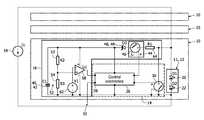
- the shunting switch 30is open or off, there is no bypass between both ends of the light unit 12 , so that the drive current I 1 may pass through the light unit 12 which, as a result, radiates light.
- the control circuit 26mainly serves to control the duty cycle of the shunting switch 30 .
- the duty cyclei.e. the ratio or frequency of on and off states of the shunting switch 30 , allows controlling the brightness and light intensity, respectively, of the LEDs 20 , 22 .
- the control signals for switching the shunting switch 30are either generated by the control circuit 26 or by a master unit. In the latter case, the control circuit 26 serves as a receiver for the switching signal DI′.
- the energy necessary for operating the control circuit 26 and the shunting switch 30is supplied to the control unit 14 by the energy storage element 40 .
- the energy stored in the energy storage element 40is provided by the current source 18 during a recharge cycle, which will be described later.
- the anode potential of the light unit 12is fed to the energy storage element 40 via the control switch 46 and the decoupling diode 48 .
- the drive current I 1will then charge the energy storage element 40 , so that the voltage across the energy storage element increases linearly over time.
- the shunting switch 30is closed again, and the control switch 46 is opened.
- the process of recharging the energy storage element 40is not started as a result of a voltage comparison, but rather, the recharging cycle is started in a fixed or selectable time pattern, for example always during each non-radiating phase.
- the recharging processis carried out for a short time which is determined on the basis of known power consumption of the circuit.
- a Z-diodemay be coupled parallel to the energy storage element 40 as an overcharging protection means.
- the control circuit 26may be adapted to monitor the voltage across the energy storage element 40 and to stop the recharging cycle when this voltage reaches a predetermined value.
Landscapes
- Electroluminescent Light Sources (AREA)
- Control Of El Displays (AREA)
- Circuit Arrangement For Electric Light Sources In General (AREA)
Abstract
Description
- a shunting switch parallel to the load,
- a control unit for controlling this shunting switch,
- an energy storage element adapted to supply energy to at least the control unit, and
- a recharge control circuitry arranged in series with the energy storage element, the series connection of energy storage element and recharge control circuitry being provided parallel to the shunting switch, wherein said control unit is adapted to activate said recharge control circuitry and to switch said shunting switch off, when said energy storage element is to be recharged.
Claims (10)
Applications Claiming Priority (4)
| Application Number | Priority Date | Filing Date | Title |
|---|---|---|---|
| EP07111559 | 2007-07-02 | ||
| EP07111559 | 2007-07-02 | ||
| EP07111559.6 | 2007-07-02 | ||
| PCT/IB2008/052616WO2009004563A1 (en) | 2007-07-02 | 2008-06-30 | Driver device for a load and method of driving a load with such a driver device |
Publications (2)
| Publication Number | Publication Date |
|---|---|
| US20100181936A1 US20100181936A1 (en) | 2010-07-22 |
| US8242710B2true US8242710B2 (en) | 2012-08-14 |
Family
ID=39971125
Family Applications (1)
| Application Number | Title | Priority Date | Filing Date |
|---|---|---|---|
| US12/666,826Active2029-04-12US8242710B2 (en) | 2007-07-02 | 2008-06-30 | Driver device for a load and method of driving a load with such a driver device |
Country Status (6)
| Country | Link |
|---|---|
| US (1) | US8242710B2 (en) |
| EP (1) | EP2165576B1 (en) |
| JP (1) | JP5337153B2 (en) |
| CN (1) | CN101690397B (en) |
| TW (1) | TWI459853B (en) |
| WO (1) | WO2009004563A1 (en) |
Cited By (8)
| Publication number | Priority date | Publication date | Assignee | Title |
|---|---|---|---|---|
| US20110210670A1 (en)* | 2008-11-13 | 2011-09-01 | Koninklijke Philips Electronics N.V. | LIGHTING SYSTEM WITH A PLURALITY OF LEDs |
| DE102013207569A1 (en)* | 2013-04-25 | 2014-11-13 | Zumtobel Lighting Gmbh | Control of bulbs within a current loop |
| US20150077007A1 (en)* | 2012-06-18 | 2015-03-19 | Tyco Fire & Security Gmbh | Current regulated led strobe drive circuit |
| DE102015003001A1 (en)* | 2015-03-07 | 2016-09-08 | Audi Ag | Remote control of a two-pole lighting device |
| DE102015003000A1 (en)* | 2015-03-07 | 2016-09-08 | Audi Ag | Remote controllable two-pole lighting device |
| US10026574B2 (en) | 2013-03-18 | 2018-07-17 | Infineon Technologies Ag | Multi-load drive circuit |
| US10153692B2 (en) | 2013-07-16 | 2018-12-11 | GE Lighting Solutions, LLC | Method and apparatus for providing supplemental power in a LED driver |
| US10801714B1 (en) | 2019-10-03 | 2020-10-13 | CarJamz, Inc. | Lighting device |
Families Citing this family (38)
| Publication number | Priority date | Publication date | Assignee | Title |
|---|---|---|---|---|
| US20050259424A1 (en) | 2004-05-18 | 2005-11-24 | Zampini Thomas L Ii | Collimating and controlling light produced by light emitting diodes |
| US7766511B2 (en) | 2006-04-24 | 2010-08-03 | Integrated Illumination Systems | LED light fixture |
| US7729941B2 (en) | 2006-11-17 | 2010-06-01 | Integrated Illumination Systems, Inc. | Apparatus and method of using lighting systems to enhance brand recognition |
| US8013538B2 (en) | 2007-01-26 | 2011-09-06 | Integrated Illumination Systems, Inc. | TRI-light |
| US8742686B2 (en) | 2007-09-24 | 2014-06-03 | Integrated Illumination Systems, Inc. | Systems and methods for providing an OEM level networked lighting system |
| CN101878673B (en)* | 2007-11-30 | 2014-02-12 | 皇家飞利浦电子股份有限公司 | light output device |
| US8255487B2 (en)* | 2008-05-16 | 2012-08-28 | Integrated Illumination Systems, Inc. | Systems and methods for communicating in a lighting network |
| US8585245B2 (en) | 2009-04-23 | 2013-11-19 | Integrated Illumination Systems, Inc. | Systems and methods for sealing a lighting fixture |
| JP5795586B2 (en)* | 2009-09-04 | 2015-10-14 | コーニンクレッカ フィリップス エヌ ヴェ | Light emitting diode circuit |
| EP2475086B1 (en)* | 2011-01-11 | 2016-08-24 | OSRAM GmbH | Power supply device, for example for light sources |
| US9066381B2 (en) | 2011-03-16 | 2015-06-23 | Integrated Illumination Systems, Inc. | System and method for low level dimming |
| US9967940B2 (en) | 2011-05-05 | 2018-05-08 | Integrated Illumination Systems, Inc. | Systems and methods for active thermal management |
| US9521725B2 (en) | 2011-07-26 | 2016-12-13 | Hunter Industries, Inc. | Systems and methods for providing power and data to lighting devices |
| US8710770B2 (en) | 2011-07-26 | 2014-04-29 | Hunter Industries, Inc. | Systems and methods for providing power and data to lighting devices |
| US20150237700A1 (en) | 2011-07-26 | 2015-08-20 | Hunter Industries, Inc. | Systems and methods to control color and brightness of lighting devices |
| US11917740B2 (en) | 2011-07-26 | 2024-02-27 | Hunter Industries, Inc. | Systems and methods for providing power and data to devices |
| US10874003B2 (en) | 2011-07-26 | 2020-12-22 | Hunter Industries, Inc. | Systems and methods for providing power and data to devices |
| US9609720B2 (en) | 2011-07-26 | 2017-03-28 | Hunter Industries, Inc. | Systems and methods for providing power and data to lighting devices |
| US9246403B2 (en)* | 2012-01-20 | 2016-01-26 | Osram Sylvania Inc. | Lighting systems with uniform LED brightness |
| KR20140124379A (en)* | 2012-01-20 | 2014-10-24 | 오스람 실바니아 인코포레이티드 | Auxiliary power supply for lighting driver circuitry |
| CN104115559B (en)* | 2012-02-01 | 2017-05-10 | 飞利浦照明控股有限公司 | Driver device and driving method for driving a load |
| USRE50126E1 (en)* | 2012-03-15 | 2024-09-17 | Signify Holding B.V. | Shunt device in lighting control system without neutral wire |
| CN104322145B (en)* | 2012-03-20 | 2017-04-26 | 飞利浦照明控股有限公司 | LED string driver circuit including charge control diodes for capacitors |
| JP5906428B2 (en)* | 2012-07-11 | 2016-04-20 | パナソニックIpマネジメント株式会社 | LED module and lighting device provided with the same |
| US8894437B2 (en) | 2012-07-19 | 2014-11-25 | Integrated Illumination Systems, Inc. | Systems and methods for connector enabling vertical removal |
| US9748858B2 (en)* | 2012-09-28 | 2017-08-29 | Osram Sylvania Inc. | Solid state light source driver establishing buck or boost operation |
| US9379578B2 (en) | 2012-11-19 | 2016-06-28 | Integrated Illumination Systems, Inc. | Systems and methods for multi-state power management |
| US9420665B2 (en) | 2012-12-28 | 2016-08-16 | Integration Illumination Systems, Inc. | Systems and methods for continuous adjustment of reference signal to control chip |
| US9485814B2 (en) | 2013-01-04 | 2016-11-01 | Integrated Illumination Systems, Inc. | Systems and methods for a hysteresis based driver using a LED as a voltage reference |
| US10228711B2 (en) | 2015-05-26 | 2019-03-12 | Hunter Industries, Inc. | Decoder systems and methods for irrigation control |
| US10918030B2 (en) | 2015-05-26 | 2021-02-16 | Hunter Industries, Inc. | Decoder systems and methods for irrigation control |
| US10060599B2 (en) | 2015-05-29 | 2018-08-28 | Integrated Illumination Systems, Inc. | Systems, methods and apparatus for programmable light fixtures |
| US10030844B2 (en) | 2015-05-29 | 2018-07-24 | Integrated Illumination Systems, Inc. | Systems, methods and apparatus for illumination using asymmetrical optics |
| CN105938703B (en)* | 2016-06-14 | 2018-11-02 | 深圳君略科技有限公司 | The driving chip, driving circuit and driving method of LED ghosts can be eliminated |
| JP6994503B2 (en)* | 2016-09-22 | 2022-01-14 | シグニファイ ホールディング ビー ヴィ | Multi-lamp lighting fixtures Retrofit light emitting diode (LED) tubes to enable step dimming in lighting systems |
| US11071180B2 (en) | 2018-03-29 | 2021-07-20 | Signify Holding B.V. | Lighting unit and driving method |
| US12416908B2 (en) | 2022-12-29 | 2025-09-16 | Integrated Illumination Systems, Inc. | Systems and methods for manufacturing light fixtures |
| US12297996B2 (en) | 2023-02-16 | 2025-05-13 | Integrated Illumination Systems, Inc. | Cove light fixture with hidden integrated air return |
Citations (17)
| Publication number | Priority date | Publication date | Assignee | Title |
|---|---|---|---|---|
| DE4228644A1 (en) | 1992-08-28 | 1994-03-03 | Tridonic Bauelemente Gmbh Dorn | AC inverter circuit for gas discharge lamp - has pair of transistors forming bridge with capacitors and circuit elements to cause alternate switching of transistors |
| EP0688152A1 (en) | 1994-06-15 | 1995-12-20 | STMicroelectronics S.A. | Circuit and device for operating a low pressure fluorescent lamp |
| WO1996002970A1 (en) | 1994-07-13 | 1996-02-01 | Auckland Uniservices Limited | Inductively powered lighting |
| WO1997013307A1 (en) | 1995-09-29 | 1997-04-10 | Pierre Vignisse | Voltage pulse controllable electronic devices |
| EP0992961A2 (en) | 1998-10-07 | 2000-04-12 | Siemens Aktiengesellschaft | Circuit for operating an illuminated sign |
| US20010033503A1 (en)* | 2000-03-28 | 2001-10-25 | Hamp Charles Henry | Low power lighting system with LED illumination |
| US20040090403A1 (en) | 2002-11-08 | 2004-05-13 | Dynascan Technology Corp. | Light-emitting diode display apparatus with low electromagnetic display |
| US6801003B2 (en)* | 2001-03-13 | 2004-10-05 | Color Kinetics, Incorporated | Systems and methods for synchronizing lighting effects |
| US6870328B2 (en) | 2001-12-19 | 2005-03-22 | Toyoda Gosei Co., Ltd. | LED lamp apparatus for vehicles |
| DE10358447B3 (en) | 2003-12-13 | 2005-05-25 | Insta Elektro Gmbh | Illumination device has series LEDs, each with parallel-connected electronic unit with low impedance switch element, diode, threshold switch, capacitor whose voltage supplies threshold switch and is fed to threshold switch as its input |
| US20050243022A1 (en) | 2004-04-30 | 2005-11-03 | Arques Technology, Inc. | Method and IC driver for series connected R, G, B LEDs |
| US20060234779A1 (en) | 2003-07-16 | 2006-10-19 | Lukas Haener | Method and device for supplying power to leds |
| US20060244396A1 (en) | 2005-04-29 | 2006-11-02 | Constantin Bucur | Serial powering of an LED string |
| US7228190B2 (en)* | 2000-06-21 | 2007-06-05 | Color Kinetics Incorporated | Method and apparatus for controlling a lighting system in response to an audio input |
| US20080012507A1 (en)* | 2006-07-07 | 2008-01-17 | Mehmet Nalbant | High Current Fast Rise And Fall Time LED Driver |
| US7528587B2 (en)* | 2005-12-27 | 2009-05-05 | Linear Technology Corporation | Switched converter with variable peak current and variable off-time control |
| US7781979B2 (en)* | 2006-11-10 | 2010-08-24 | Philips Solid-State Lighting Solutions, Inc. | Methods and apparatus for controlling series-connected LEDs |
Family Cites Families (4)
| Publication number | Priority date | Publication date | Assignee | Title |
|---|---|---|---|---|
| JPH10106782A (en)* | 1996-09-30 | 1998-04-24 | Toshiba Lighting & Technol Corp | Discharge lamp lighting device and lighting device |
| US7106602B2 (en)* | 2003-07-29 | 2006-09-12 | Astec International Limited | Switching-bursting method and apparatus for reducing standby power and improving load regulation in a DC—DC converter |
| CA2768198C (en)* | 2005-04-08 | 2013-11-26 | Eldolab Holding B.V. | Methods and apparatuses for operating groups of high-power leds |
| CN101154886A (en)* | 2006-09-30 | 2008-04-02 | 硕颉科技股份有限公司 | DC-DC conversion circuit and controller thereof |
- 2008
- 2008-06-30EPEP08789176.8Apatent/EP2165576B1/enactiveActive
- 2008-06-30USUS12/666,826patent/US8242710B2/enactiveActive
- 2008-06-30WOPCT/IB2008/052616patent/WO2009004563A1/enactiveApplication Filing
- 2008-06-30TWTW097124610Apatent/TWI459853B/enactive
- 2008-06-30JPJP2010514221Apatent/JP5337153B2/enactiveActive
- 2008-06-30CNCN2008800233502Apatent/CN101690397B/enactiveActive
Patent Citations (17)
| Publication number | Priority date | Publication date | Assignee | Title |
|---|---|---|---|---|
| DE4228644A1 (en) | 1992-08-28 | 1994-03-03 | Tridonic Bauelemente Gmbh Dorn | AC inverter circuit for gas discharge lamp - has pair of transistors forming bridge with capacitors and circuit elements to cause alternate switching of transistors |
| EP0688152A1 (en) | 1994-06-15 | 1995-12-20 | STMicroelectronics S.A. | Circuit and device for operating a low pressure fluorescent lamp |
| WO1996002970A1 (en) | 1994-07-13 | 1996-02-01 | Auckland Uniservices Limited | Inductively powered lighting |
| WO1997013307A1 (en) | 1995-09-29 | 1997-04-10 | Pierre Vignisse | Voltage pulse controllable electronic devices |
| EP0992961A2 (en) | 1998-10-07 | 2000-04-12 | Siemens Aktiengesellschaft | Circuit for operating an illuminated sign |
| US20010033503A1 (en)* | 2000-03-28 | 2001-10-25 | Hamp Charles Henry | Low power lighting system with LED illumination |
| US7228190B2 (en)* | 2000-06-21 | 2007-06-05 | Color Kinetics Incorporated | Method and apparatus for controlling a lighting system in response to an audio input |
| US6801003B2 (en)* | 2001-03-13 | 2004-10-05 | Color Kinetics, Incorporated | Systems and methods for synchronizing lighting effects |
| US6870328B2 (en) | 2001-12-19 | 2005-03-22 | Toyoda Gosei Co., Ltd. | LED lamp apparatus for vehicles |
| US20040090403A1 (en) | 2002-11-08 | 2004-05-13 | Dynascan Technology Corp. | Light-emitting diode display apparatus with low electromagnetic display |
| US20060234779A1 (en) | 2003-07-16 | 2006-10-19 | Lukas Haener | Method and device for supplying power to leds |
| DE10358447B3 (en) | 2003-12-13 | 2005-05-25 | Insta Elektro Gmbh | Illumination device has series LEDs, each with parallel-connected electronic unit with low impedance switch element, diode, threshold switch, capacitor whose voltage supplies threshold switch and is fed to threshold switch as its input |
| US20050243022A1 (en) | 2004-04-30 | 2005-11-03 | Arques Technology, Inc. | Method and IC driver for series connected R, G, B LEDs |
| US20060244396A1 (en) | 2005-04-29 | 2006-11-02 | Constantin Bucur | Serial powering of an LED string |
| US7528587B2 (en)* | 2005-12-27 | 2009-05-05 | Linear Technology Corporation | Switched converter with variable peak current and variable off-time control |
| US20080012507A1 (en)* | 2006-07-07 | 2008-01-17 | Mehmet Nalbant | High Current Fast Rise And Fall Time LED Driver |
| US7781979B2 (en)* | 2006-11-10 | 2010-08-24 | Philips Solid-State Lighting Solutions, Inc. | Methods and apparatus for controlling series-connected LEDs |
Cited By (13)
| Publication number | Priority date | Publication date | Assignee | Title |
|---|---|---|---|---|
| US20110210670A1 (en)* | 2008-11-13 | 2011-09-01 | Koninklijke Philips Electronics N.V. | LIGHTING SYSTEM WITH A PLURALITY OF LEDs |
| US9801243B2 (en)* | 2008-11-13 | 2017-10-24 | Philips Lighting Holding B.V. | Lighting system with a plurality of LEDs |
| US9345082B2 (en)* | 2012-06-18 | 2016-05-17 | Tyco Fire & Security Gmbh | Current regulated LED strobe drive circuit |
| US20150077007A1 (en)* | 2012-06-18 | 2015-03-19 | Tyco Fire & Security Gmbh | Current regulated led strobe drive circuit |
| US10026574B2 (en) | 2013-03-18 | 2018-07-17 | Infineon Technologies Ag | Multi-load drive circuit |
| DE102013207569A1 (en)* | 2013-04-25 | 2014-11-13 | Zumtobel Lighting Gmbh | Control of bulbs within a current loop |
| US10153692B2 (en) | 2013-07-16 | 2018-12-11 | GE Lighting Solutions, LLC | Method and apparatus for providing supplemental power in a LED driver |
| DE102015003001A1 (en)* | 2015-03-07 | 2016-09-08 | Audi Ag | Remote control of a two-pole lighting device |
| DE102015003000A1 (en)* | 2015-03-07 | 2016-09-08 | Audi Ag | Remote controllable two-pole lighting device |
| DE102015003001B4 (en) | 2015-03-07 | 2022-07-14 | Audi Ag | Remote control of a two-pole lighting device |
| DE102015003000B4 (en) | 2015-03-07 | 2022-08-18 | Audi Ag | Remote controllable two-pole lighting device |
| US10801714B1 (en) | 2019-10-03 | 2020-10-13 | CarJamz, Inc. | Lighting device |
| US11054127B2 (en) | 2019-10-03 | 2021-07-06 | CarJamz Com, Inc. | Lighting device |
Also Published As
| Publication number | Publication date |
|---|---|
| JP2010532092A (en) | 2010-09-30 |
| CN101690397A (en) | 2010-03-31 |
| TWI459853B (en) | 2014-11-01 |
| CN101690397B (en) | 2012-07-18 |
| EP2165576A1 (en) | 2010-03-24 |
| JP5337153B2 (en) | 2013-11-06 |
| WO2009004563A1 (en) | 2009-01-08 |
| TW200922370A (en) | 2009-05-16 |
| US20100181936A1 (en) | 2010-07-22 |
| EP2165576B1 (en) | 2018-08-08 |
Similar Documents
| Publication | Publication Date | Title |
|---|---|---|
| US8242710B2 (en) | Driver device for a load and method of driving a load with such a driver device | |
| RU2428822C2 (en) | Matrix of luminous elements with controlled current sources and action method | |
| US8125159B2 (en) | LED driving device with variable light intensity | |
| US7436125B2 (en) | Light emitting diode drive circuit | |
| CN107667464B (en) | LED driver and driving method | |
| US9769890B1 (en) | Circuit and method for eliminating power-off flash for LED drivers | |
| JP2007258671A (en) | LED drive circuit | |
| TWI554146B (en) | Semiconductor light source apparatus and semiconductor light source control method | |
| EP2695485B1 (en) | Driver device and driving method for driving a load, in particular an led assembly | |
| EP2608638B1 (en) | Lighting device and illumination apparatus including same | |
| EP3244698B1 (en) | Light emitting system comprising a supply circuit for an led controller | |
| CN106688309A (en) | LED dimmer circuit and method | |
| US9992826B1 (en) | Dual mode constant current LED driver | |
| US20140226688A1 (en) | Multiple output diode driver with independent current control and output current modulation | |
| US20150288293A1 (en) | Auxiliary power supply for ac powered electronics | |
| EP3741189A1 (en) | Constant current driver charging energy storage unit | |
| US12389505B2 (en) | Light turn-off fade time control | |
| JP7724226B2 (en) | LED lighting system and control method | |
| US9130465B2 (en) | Minimum off time control systems and methods for switching power converters in discontinuous conduction mode | |
| CN109149930B (en) | Pulse width modulation voltage-stabilized source | |
| US20250142700A1 (en) | Led switching power supply | |
| US11290012B2 (en) | Converter with selectable output-voltage ranges | |
| US10461532B2 (en) | Supplying an electrical load with electrical energy from a voltage source | |
| CN117099483A (en) | Optical turn-off decay time control |
Legal Events
| Date | Code | Title | Description |
|---|---|---|---|
| AS | Assignment | Owner name:KONINKLIJKE PHILIPS ELECTRONICS N V, NETHERLANDS Free format text:ASSIGNMENT OF ASSIGNORS INTEREST;ASSIGNORS:RADERMACHER, HARALD JOSEF GUENTHER;WENDT, MATTHIAS;REEL/FRAME:023706/0245 Effective date:20090616 | |
| STCF | Information on status: patent grant | Free format text:PATENTED CASE | |
| FPAY | Fee payment | Year of fee payment:4 | |
| AS | Assignment | Owner name:KONINKLIJKE PHILIPS N.V., NETHERLANDS Free format text:CHANGE OF NAME;ASSIGNOR:KONINKLIJKE PHILIPS ELECTRONICS N.V.;REEL/FRAME:039428/0606 Effective date:20130515 | |
| AS | Assignment | Owner name:PHILIPS LIGHTING HOLDING B.V., NETHERLANDS Free format text:ASSIGNMENT OF ASSIGNORS INTEREST;ASSIGNOR:KONINKLIJKE PHILIPS N.V.;REEL/FRAME:040060/0009 Effective date:20160607 | |
| AS | Assignment | Owner name:SIGNIFY HOLDING B.V., NETHERLANDS Free format text:CHANGE OF NAME;ASSIGNOR:PHILIPS LIGHTING HOLDING B.V.;REEL/FRAME:050837/0576 Effective date:20190201 | |
| MAFP | Maintenance fee payment | Free format text:PAYMENT OF MAINTENANCE FEE, 8TH YEAR, LARGE ENTITY (ORIGINAL EVENT CODE: M1552); ENTITY STATUS OF PATENT OWNER: LARGE ENTITY Year of fee payment:8 | |
| MAFP | Maintenance fee payment | Free format text:PAYMENT OF MAINTENANCE FEE, 12TH YEAR, LARGE ENTITY (ORIGINAL EVENT CODE: M1553); ENTITY STATUS OF PATENT OWNER: LARGE ENTITY Year of fee payment:12 |