US8242476B2 - LED object detection system and method combining complete reflection traces from individual narrow field-of-view channels - Google Patents
LED object detection system and method combining complete reflection traces from individual narrow field-of-view channelsDownload PDFInfo
- Publication number
- US8242476B2 US8242476B2US12/949,212US94921210AUS8242476B2US 8242476 B2US8242476 B2US 8242476B2US 94921210 AUS94921210 AUS 94921210AUS 8242476 B2US8242476 B2US 8242476B2
- Authority
- US
- United States
- Prior art keywords
- environment
- light source
- led light
- led
- individual
- Prior art date
- Legal status (The legal status is an assumption and is not a legal conclusion. Google has not performed a legal analysis and makes no representation as to the accuracy of the status listed.)
- Active
Links
Images


Classifications
- G—PHYSICS
- G01—MEASURING; TESTING
- G01S—RADIO DIRECTION-FINDING; RADIO NAVIGATION; DETERMINING DISTANCE OR VELOCITY BY USE OF RADIO WAVES; LOCATING OR PRESENCE-DETECTING BY USE OF THE REFLECTION OR RERADIATION OF RADIO WAVES; ANALOGOUS ARRANGEMENTS USING OTHER WAVES
- G01S7/00—Details of systems according to groups G01S13/00, G01S15/00, G01S17/00
- G01S7/48—Details of systems according to groups G01S13/00, G01S15/00, G01S17/00 of systems according to group G01S17/00
- G01S7/481—Constructional features, e.g. arrangements of optical elements
- G01S7/4814—Constructional features, e.g. arrangements of optical elements of transmitters alone
- G—PHYSICS
- G01—MEASURING; TESTING
- G01S—RADIO DIRECTION-FINDING; RADIO NAVIGATION; DETERMINING DISTANCE OR VELOCITY BY USE OF RADIO WAVES; LOCATING OR PRESENCE-DETECTING BY USE OF THE REFLECTION OR RERADIATION OF RADIO WAVES; ANALOGOUS ARRANGEMENTS USING OTHER WAVES
- G01S17/00—Systems using the reflection or reradiation of electromagnetic waves other than radio waves, e.g. lidar systems
- G01S17/02—Systems using the reflection of electromagnetic waves other than radio waves
- G01S17/06—Systems determining position data of a target
- G01S17/42—Simultaneous measurement of distance and other co-ordinates
- G—PHYSICS
- G01—MEASURING; TESTING
- G01S—RADIO DIRECTION-FINDING; RADIO NAVIGATION; DETERMINING DISTANCE OR VELOCITY BY USE OF RADIO WAVES; LOCATING OR PRESENCE-DETECTING BY USE OF THE REFLECTION OR RERADIATION OF RADIO WAVES; ANALOGOUS ARRANGEMENTS USING OTHER WAVES
- G01S17/00—Systems using the reflection or reradiation of electromagnetic waves other than radio waves, e.g. lidar systems
- G01S17/88—Lidar systems specially adapted for specific applications
- G01S17/93—Lidar systems specially adapted for specific applications for anti-collision purposes
- G01S17/931—Lidar systems specially adapted for specific applications for anti-collision purposes of land vehicles
Definitions
- the present inventiongenerally relates to object detection systems and more particularly to multi-channel object detection systems using light emitted by a LED light source.
- a range finderis an instrument used to measure the distance from the instrument to a selected point or object.
- the optical range finderused chiefly in cameras, consists of an arrangement of lenses and prisms set at each end of a tube. The object's range is determined by measuring the angles formed by a line of sight at each end of the tube; the smaller the angles, the greater the distance, and vice versa. Since the mid-1940s, radar has replaced optical range finders for most military targeting, and the laser range finder, developed in 1965, has largely replaced optical range finders for surveying and radar in certain military applications.
- the most common form of laser rangefinderoperates on the time of flight principle by sending a laser pulse in a narrow beam towards the object and measuring the time taken by the pulse to be reflected off the target and returned to the sender.
- Lasershave the property of efficiently collimating their beam and therefore concentrate their energy in a narrow angular range.
- the Field-of-illumination (FOI) of the laser rangefinderis therefore much narrower than the Field-of-view (FOV) of the detector.
- the concentrated laser beamhas many advantages. If the surface of the object reflects a great portion of the laser beam it receives toward the detector, it is very efficient. However, if the surface of the object is not exactly at a right angle to the beam and it has some specular reflection effects, the major portion of the reflection will be oriented in a direction other than that of the detector. The object will then not be detected. Additionally, if some sections of the surface of an object illuminated by the laser beam have very poor reflectivity, the amplitude of the reflection received by the detector will not be enough to reach the preset threshold and the object will not be detected. The laser rangefinder therefore presents reliability issues.
- a caris a good example of an object which has surfaces with varying reflectivity and portions with different shapes and angles.
- Some sections of the car which have very high reflectivity, such as the retro-reflector typically located at the back of the vehicleswill have extremely high reflectivity toward the source but are very small in size and unlikely to receive the very collimated beam of the laser source.
- Some sections of the car with varying shapeswill reflect the very collimated beam of the laser source in many different directions and not necessarily toward the detector and may therefore go undetected.
- a method for detecting an object located in an environmentA Light-Emitting-Diode (LED) light source having a wide field-of-illumination is provided and oriented such that the wide field-of-illumination encompasses a width of the environment.
- An optical detector having a wide field-of-viewis provided and oriented such that the wide field-of-view encompasses the width of the environment.
- the LED light sourceis driven into emitting light toward the environment, the width of the environment being illuminated by the light.
- a complete trace of a reflection/backscatter of the emitted light on the object in the environmentis received and acquired using the optical detector.
- the acquired complete trace of the reflection/backscatteris then converted into a digital signal.
- a step of detecting and identifyingis carried out to detect and identify at least one of a presence of an object in the environment, a position of the object in the environment, a distance between the object and the LED light source and a visibility in the environment, using the digital signal.
- the optical detectorcan include a plurality of optical sub-detectors, each having an individual narrow field-of-view.
- the optical sub-detectorscan detect simultaneously, in sequence or in combination.
- their fields-of-viewcan overlap partly or completely or they can be adjacent to one another.
- each optical sub-detectoris able to receive and acquire a complete trace of the reflection for its own field-of-view, thereby creating a channel in the environment in which it is acquiring.
- the use of a plurality of sub-detectorsallows a multichannel object detection.
- the detectioncan be performed in one, multiple or all channels.
- a multi-channel LED object detection systemfor detecting an object located in an environment.
- itincludes a Light-Emitting-Diode (LED) light source having a wide field-of-illumination oriented for the wide field-of-illumination to encompass the width of the environment; a source controller for the LED light source for driving the LED light source into emitting light toward the environment, the width of the environment being illuminated by the light; an optical detector having a wide field-of-view oriented for the wide field-of-view to encompass the width of the environment, the optical detector receiving a complete trace of a reflection/backscatter of the emitted light on the object in the environment; an analog-to-digital converter for converting the complete trace of the reflection/backscatter into a digital signal; a memory for acquiring and storing the complete trace; and a signal processor for detecting and identifying at least one of a presence of an object in the environment, a position of the object in the environment and a distance
- LEDLight-Emitting-
- a method for detecting an object located in an environmentincludes providing a Light-Emitting-Diode (LED) light source having a wide field-of-illumination and orienting the LED light source for the wide field-of-illumination to encompass the width of the environment; providing an optical detector having a wide field-of-view and orienting the optical detector for the wide field-of-view to encompass the width of the environment, the optical detector having a plurality of sub-detectors, each having an individual narrow field-of-view, each individual narrow field-of-view creating a channel in the wide field-of-view; driving the LED light source into emitting light toward the environment, the width of the environment being illuminated by the light, the light having an emitted light waveform; receiving and acquiring an individual complete trace of a reflection/backscatter of the emitted light on the object in the environment at each sub-detector of the plurality, thereby combining the individual narrow field-of-view to create the wide
- LEDLight-Emitting-
- a multi-channel LED object detection systemfor detecting an object located in an environment. It includes a Light-Emitting-Diode (LED) light source having a wide field-of-illumination oriented for the wide field-of-illumination to encompass the width of the environment; a source controller for the LED light source for driving the LED light source into emitting light toward the environment, the width of the environment being illuminated by the light, the light having an emitted light waveform; an optical detector having a wide field-of-view oriented for the wide field-of-view to encompass the width of the environment, the optical detector having a plurality of sub-detectors, each having an individual narrow field-of-view, each individual narrow field-of-view creating a channel in the wide field-of-view, the optical detector receiving an individual complete trace of a reflection/backscatter of the emitted light on the object in the environment at each sub-detector of the plurality, thereby combining the individual narrow field-of-view to create
- LEDLight-E
- non-visibleis intended to be a synonym of the terms “invisible” and “nonvisible” and to be an antonym to the word “visible”. It should be understood that “visible light” refers to light emitted at wavelengths which are visible to the human eye. Similarly, “invisible light” refers to light emitted at wavelengths which are not visible to the human eye.
- vehicleis intended to include any movable means of transportation for cargo, humans and animals, not necessarily restricted to ground transportation, including wheeled and unwheeled vehicles, such as, for example, a truck, a bus, a boat, a subway car, a train wagon, an aerial tramway car, a ski lift, a plane, a car, a motorcycle, a tricycle, a bicycle, a SegwayTM, a carriage, a wheelbarrow, a stroller, etc.
- wheeled and unwheeled vehiclessuch as, for example, a truck, a bus, a boat, a subway car, a train wagon, an aerial tramway car, a ski lift, a plane, a car, a motorcycle, a tricycle, a bicycle, a SegwayTM, a carriage, a wheelbarrow, a stroller, etc.
- the term “environmental particle”is intended to include any particle detectable in the air or on the ground and which is typically caused by an environmental, chemical or natural phenomenon. It includes fog, rain, snow, smoke, gas, smog, black ice, hail, etc.
- objectis intended to include a moving object and a stationary object.
- objectcan be a vehicle, an environmental particle, a person, a passenger, an animal, a gas, a liquid, a particle such as dust, a pavement, a wall, a post, a sidewalk, a ground surface, a tree, etc.
- the term “wide”is intended to be the opposite of “narrow”.
- the terms “narrow” and “wide”refer to sizes of the field-of-illumination, field-of-view, channel and environment. They are intended to describe a measurement in any 3D direction, namely in width, height or length, depending on the orientation of the LED light source and of the optical detector.
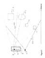
- FIG. 1is a block diagram illustrating an example multi-channel LED object detection system
- FIG. 2is a schematic view of an example multi-channel LED object detection system, with multiple detectors;
- FIG. 3is a schematic view of an example multi-channel LED object detection system, using a detector array
- FIG. 4is a schematic view of example multi-channel LED object detection system, using a light source array.
- FIG. 5is a schematic view of an example multi-channel LED object detection system, with a lens and a diffuser.
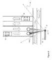
- FIG. 6is a schematic view of an example multi-channel LED object detection system, in a traffic application
- FIG. 7is a schematic view a calibration of an example multi-channel LED object detection system.
- FIG. 8is a schematic view of a street light equipped with an example multi-channel LED object detection system and detecting a vehicle.
- a multichannel LED object detecting system in accordance with one example embodimentis generally shown at 10 .
- the system 10has at least one LED as a LED light source 12 .
- the LED light source 12can be invisible, visible or can include LEDs of both types.
- the LED light source 12is connected to a source controller 14 which is also referred to as the Pulse/Modulation driver 14 , so as to be driven into producing illumination.
- the system 10performs the detection of objects when these objects are part of the environment/scene illuminated by the LED light source 12 .
- the source controller 14drives the LED light source 12 such that the emitted light can take the form of a light signal, for instance by way of amplitude-modulated or pulsed light emission, either in the visible or non-visible range of wavelengths.
- All LEDs in a single modulecan be controlled by the same control signal or each one or a cluster of LEDs can be controlled by several independent control signals from the source controller 14 .
- Each LED, or cluster of LEDscan be controlled to create a beam pattern to meet the needs in terms of detection in the scene. Several beams can be used individually to illuminate the scene.
- a modulated/pulsed driving signalsupplies the fast modulation/pulse sequence required for remote object detection.
- the amplitude of short-pulse(typ. ⁇ 50 ns) can be several times the nominal value (typ. 10 to 100) while the duty cycle is low (typ. ⁇ 0.1%)
- the system 10can have at least one optical component 22 , typically lenses and/or diffusers, which is used for the collimation and the distribution of the optical output of LED(s) and make the illumination for the scene in concordance with FOV of the detection zone. Reflectors can also be used to redirect the light.
- Optical component 22can be integrated in a window that also includes a lens for the optical detector.
- An optical detector array 16(or a plurality of optical detectors) associated with the LED light source 12 and an optical lens 30 collects the light emitted by the LED light source 12 and back-scattered by the objects A.
- the optical detector array 16receives an echo back signal from an object in the FOV.
- Each pixel of the detector array 16acts as a discrete detector with a specific field of view (FOV) and probes a specific portion of the illuminated scene.
- FOVfield of view
- the light signalcan also come from an object A being the direct source of this light (such as a remote control) in order to send information to the data/signal processor 18 through the optical detector 16 .
- the optical detector 16is as an example any of photodiodes, avalanche photodiodes (APD), photomultipliers (PMT), CCD or CMOS array sensors, amongst others. Other array sensors can be integrated, thermal sensor for instance.
- a wavelength measurement sensorcan be integrated to measure the drift of the light source and estimate the temperature of the LEDs for lifetime assessment, temperature control and maintenance purposes.
- the optical detector 16may be separate from the LED light source 12 and integrated with other electronics parts elsewhere.
- Filtersare typically provided with the detector 16 to attenuate ambient light background emitted from sources other than the system 10 . Filters can also be used for spectroscopic measurements and to enhance performance of the LED light source 12 .
- a database 20may be provided in association with the data/signal processor 18 so as to provide historical data, or tabulated data to accelerate the calculation of the object parameters.
- a signature modulationis considered so as to avoid interference between signals of the different multichannel LED object detecting system 10 .
- a front-end and analog-to-digital converter (ADC) 24is connected to detector 16 and receives detected light data therefrom and controls the detector. Gain of amplifier and other adjustment can be controlled.
- the front-end and ADC 24can have several parallel channels to digitalize the information or a multiplexer for acquiring at least two optical sensing elements.
- a detection and ranging processing unit 26is connected to the front-end 24 , controls parameters such as gain of amplifier, synchronization and sample rate of the ADC, receives data from ADC and processes the data. Shift control for acquisition can improve accuracy with the same ADC sampling rate. For instance, a 20MSPS ADC can have an improved resolution if successive acquisitions are delayed y an equivalent fraction of the acquisition time period. A better resolution increases the precision when measuring the rise time or the peak position of the signal.
- Interpolation and differential calculuscan be processed by the detection and ranging processing unit 26 to increase the precision.
- Averagingis another pre-process treatment to improve signal/noise ratio.
- Other techniqueslike a moving-average filter improve the performance.
- Match filterinput/output signals
- An objectcan also be locked and followed with FFT processing.
- a specific processing functioncan be used for each point of the LIDAR trace.
- more samplescan be averaged for a point which represents farther distance (trade-off between signal-to-noise ratio and number of results per second).
- More shift control (delay)can be used for acquisition in the short range (more resolution to measure the distance) and more samples typically result in a better signal-to-noise ratio for acquisition in the long range.
- Specific processingcan be used for overlapping regions at a certain distance covered by more than one detector.
- the detection and ranging processing unit 26can also be used for pre-process speed computation. Some environmental/weather conditions like fog, snow, rain, or dust, to name a few, can be estimated, whereby slid objects and slippery surfaces can be detected. The cleanliness of the optical components and the required maintenance can also be detected.
- the data/signal processor 18is connected to the detection and ranging processing unit 26 , and receives pre-processed data.
- the source controller 14receives its driving data from the data/signal processor and/or from the detection & ranging processing unit 26 .
- the data/signal processor 18 and the detection and ranging processing unit 26could be combined into a single unit.
- the data/signal processor 18has a processing unit (e.g., CPU) so as to interpret the pre-processed data from the detection and ranging processing unit 26 , in comparison with the driving data of the source controller 14 , which provides information about the emission of the light signals emitted by the LED light source 12 .
- a processing unite.g., CPU
- information about the objectis calculated by the data/signal processor 18 as a function of the relation (e.g., phase difference, relative intensity, spectral content, time of flight, etc.) between the driving data and the detected light data, as optionally pre-processed by the front-end and ADC 24 and the detection and ranging processing unit 26 .
- the speed of the objectcan also be measured with the modulation phase shift measurement (or time of flight of pulsed light) technique described previously.
- the measurement of vehicle speedis also possible either by distance measurement.
- the system 10has a power supply and interface 28 .
- the interface 28is connected to the data/signal processor 18 and is in communication with External system B.
- the interface 28could be Ethernet, PoE, CANbus, USB or any other interface type.
- the system 10has sensors 32 connected to data/signal processor 18 .
- Sensors 32are composed with an inclinometer, accelerometer, speedometer, temperature sensor, day/night sensor to name a few type of sensors. Those sensors 32 are useful during the installation and during operation. For instance, data from inclinometer, speedometer, and accelerometer are useful to compensate for the impact on the field of view by the effect of vibration and speed.
- Temperature sensorsare useful to provide information about weather (internal, external or remote temperature with FIR lens). Thermal sensor can be useful to determine the temperature of objects and classify these objects (human, animals, vehicles, trees, etc.).
- the data/signal processor 18controls the source controller 14 and thus the light output of the LED light source 12 .
- the LED light source 12may be required to increase or reduce its intensity, or change the parameters of its output.
- the data/signal processor 18may send the calculation output to External system B in such a way that the External system B acts upon the information provided by the data/signal processor 18 .
- the External system Bcan also give input parameters/commands to be used to the data/signal processor 18 . These parameters can be adjustments to be performed to current calibration, new programs to be implemented for the current application, or data to be added to the database 20 . This information can be used by the data/signal processor 18 to complete its operation.
- an alternative embodiment of the sensor configurationinvolves a plurality of discrete detectors 52 , 53 , 54 , 55 , each observing a respective fixed field of view FOVA through FOVD within a volume of space illuminated by the light source 51 and comprising objects A through D.
- Fields of view of the detectorsare narrow or might be a combination of narrow and wide field of views as a trade-off between distance accuracy and number of detectors necessary.
- the optical detectoris as an example any of photodiodes, APD or PMT. Such a configuration provides simplicity of design at the price of increased number of components and less intuitive integration.
- a detection array 72is used with a large field of view FOVM encompassing the whole illuminated scene.
- Each pixel of the array 72acts as a discrete detector with a very narrow field of view and probes a specific portion of the illuminated scene, as determined by any secondary optics in front of the array.
- the array 72is any linear or 2D type array, such as APD or photodiode arrays, CCD and CMOS sensors.
- the light source 82is composed of multiple individual lighting elements 83 , 84 (e.g. LEDs or small clusters of LEDs) that are driven by the source controller 14 to be turned on simultaneously or in sequence.
- the driven light element, illustrated by 83illuminates only a portion of the scene with a small or narrow field of view FOVS, as determined by the appropriately designed secondary optics, while the other elements 84 are turned off.
- the secondary opticsmay take various forms (e.g., bulk, fiber) in accordance with the application.
- a detector 81including multiple sub-detectors (not shown), with a large or wide field of view FOVL encompassing the entire illuminated scene will be sensitive only to objects within FOVS (for example, Object C in FIG. 4 ).
- the detector 81may be any of a photodiode, an APD, a PMT or equivalent thereof.
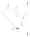
- At least one LED light source 110emits photons 112 (visible or invisible) with a very wide angle (120° for instance).
- a primary optic 114typically a nonimaging optical lens or concentrator, is used for the collimation of the optical output of LED(s) and make a LED beam 116 .
- a secondary optic 118typically a diffuser, is used to produce the required irradiance distribution 120 with homogeneous illumination all over the FOI and in concordance with FOV of the detection zone.
- An optical detector array 122 and an optical lens 124received echo back signal from object in the FOV (pedestrian A, object B and C, car D, Cyclist and/or its bicycle E, Pavement F). Each pixel of the detector array 122 acts as a discrete detector with a narrow field of view and probe a specific portion of the illuminated scene.
- FIG. 6shows an application of an example multichannel LED object detection system.
- the systemis installed in a traffic application.
- the traffic light unit 60is fitted with a light source 62 and an optical detector 64 .
- the optical detector 64comprises a plurality of sub-detectors.
- the field-of-view of two of the sub-detectorsare shown as FOV 1 and FOV 2 .
- the field of illumination of the LED light sourceis shown as FOI and encompasses the whole width of the environment in which objects are to be detected.
- Car 66is approaching the area where it will be located in the FOV 1 of a sub-detector of optical detector 64 .
- the multichannel LED object detection systemwill be able to detect its presence in FOV 1 when it reaches the area of detection.
- a maximal detection zoneis chosen at the time of installation of the system.
- This environment, scene or detection zoneis a volume within which objects are to be detected.
- This detection zonehas a width, a height and a depth.
- the detection zonewill be somewhat rectangular in shape, covering a region of interest in side-by-side traffic lanes.
- the regioncould be located about 15 m from the LED light source for a depth of 10 m, for a height of a 10 m and for a width equal to the width of the traffic lanes to monitor with the detection system.
- Each channel of the multichannel LED object detection systemwill be installed and calibrated so that it monitors a region of interest in the traffic circulation, for example, two traffic lanes for circulation in one direction, one bi-directional cycle lane (not shown) and one pedestrian crossing waiting zone (not shown).
- the width of the overall detection zoneis likely to be greater than the depth and height of the detection zone thereby creating a horizontal rectangular zone.
- the wide field of illumination of the LED light sourceis then the width of the detection zone.
- the multichannel LED object detection systemis also rectangular but in a vertical orientation.
- the detection systemcan be used for parking assistance to detect the presence of a sidewalk, curb, mailbox, parking meter, street lamp post, vehicle, bicycle, etc.
- the detection zoneis then defined to be a vertically elongated region in front of the front or the back of the vehicle. The height of the region is greater than the width and the length of the region. The wide field of illumination of the LED light source is then the height of the detection zone.
- the calibration processis schematized.
- the limits of the field of view of the detectorare associated with a distance from the traffic light unit, so as to calibrate the detector.
- informationmay be entered using a user interface of the data/signal processor 18 .
- the multichannel LED object detection systemis shown in a street lamp application.
- the detection zoneis conic in shape, the base of the prism being somewhat square.
- the width and length of the regionwill be of similar dimension and the height will be small.
- the wide field of illumination of the LED light sourcecan then be either the width or the length of the detection zone. Therefore, upon detecting a vehicle, the street light 90 signals the detection to the external system B ( FIG. 1 ).
- the external system Bforwards the information or commands to an appropriate traffic light, for example to control the emission of signals.
- the measurement of vehicle speedis also possible either by distance measurement or by measurement of their time of passage at different points along the street lane beneath the LED street-lighting devices.
- a method for detecting an object located in an environmentcan include a few steps.
- a Light-Emitting-Diode (LED) light source having a wide field-of-illuminationis provided and oriented such that the wide field-of-illumination encompasses a width of the environment.
- An optical detector having a wide field-of-viewis provided and oriented such that the wide field-of-view encompasses the width of the environment.
- the LED light sourceis driven into emitting light toward the environment, the width of the environment being illuminated by the light.
- a complete trace of a reflection/backscatter of the emitted light on the object in the environmentis received and acquired a using the optical detector.
- the acquired complete trace of the reflection/backscatteris then converted into a digital signal.
- a step of detecting and identifyingis carried out to detect and identify at least one of a presence of an object in the environment, a position of the object in the environment, a distance between the object and the LED light source and a visibility in the environment, using the digital signal.
- the LED light sourcecan be a visible or invisible LED light source.
- the LED light sourcecan also include a plurality of LEDs. If the LED light source includes a plurality of LEDs, none, some or all of the LEDs can be invisible LEDs. If a plurality of LEDs is used, they can be driven to illuminate simultaneously, in sequence or in combination. Their fields-of-illumination can overlap partly or completely or they can be adjacent to one another.
- the optical detectorcan include a plurality of optical sub-detectors, each having an individual narrow field-of-view.
- the optical sub-detectorscan detect simultaneously, in sequence or in combination. Their fields-of-view can overlap partly or completely or they can be adjacent to one another.
- Each optical sub-detectoris able to receive and acquire a complete trace of the reflection for its own field-of-view, thereby creating a channel in the environment in which it is acquiring.
- the use of a plurality of sub-detectorsallows a multichannel object detection. The detection can be performed in one, multiple or all channels. Regardless of whether a single or a plurality of optical detectors is used, the steps of the method can be repeated to receive and acquire additional time-spaced complete traces for each channel.
- the individual traces from different channels or the time-spaced traces for a single channelcan be analyzed in combination to further detect and identify objects and properties of these objects, such as a displacement speed of the object, a shape of the object and a
- a multi-channel LED object detection systemfor detecting an object located in an environment can include the following components: a Light-Emitting-Diode (LED) light source having a wide field-of-illumination oriented for the wide field-of-illumination to encompass the width of the environment; a source controller for the LED light source for driving the LED light source into emitting light toward the environment, the width of the environment being illuminated by the light; an optical detector having a wide field-of-view oriented for the wide field-of-view to encompass the width of the environment, the optical detector receiving a complete trace of a reflection/backscatter of the emitted light on the object in the environment; an analog-to-digital converter for converting the complete trace of the reflection/backscatter into a digital signal; a memory for acquiring and storing the complete trace; and a signal processor for detecting and identifying at least one of a presence of an object in the environment, a position of the object in the environment and a distance between the object and the LED
- An infrared LED light sourcecan be used.
- the multi-channel LED object detection systemcan further include a lens and a diffuser, the lens for collimating the power of the light source, the diffuser for diffusing the collimated power to illuminate the environment.
- the wide field-of-illuminationcan have an angular range of more than 10 degrees in one embodiment. In one embodiment, the angular range is between 15 and 180 degrees. In one embodiment, the angular range is between 15 and 90 degrees.
Landscapes
- Physics & Mathematics (AREA)
- Engineering & Computer Science (AREA)
- Electromagnetism (AREA)
- Computer Networks & Wireless Communication (AREA)
- General Physics & Mathematics (AREA)
- Radar, Positioning & Navigation (AREA)
- Remote Sensing (AREA)
- Optical Radar Systems And Details Thereof (AREA)
- Length Measuring Devices By Optical Means (AREA)
Abstract
Description
Claims (22)
Priority Applications (1)
| Application Number | Priority Date | Filing Date | Title |
|---|---|---|---|
| US12/949,212US8242476B2 (en) | 2005-12-19 | 2010-11-18 | LED object detection system and method combining complete reflection traces from individual narrow field-of-view channels |
Applications Claiming Priority (9)
| Application Number | Priority Date | Filing Date | Title |
|---|---|---|---|
| US75128405P | 2005-12-19 | 2005-12-19 | |
| US11/612,678US7855376B2 (en) | 2005-12-19 | 2006-12-19 | Lighting system and method for illuminating and detecting object |
| US94465807P | 2007-06-18 | 2007-06-18 | |
| US94465707P | 2007-06-18 | 2007-06-18 | |
| PCT/CA2008/001160WO2008154736A1 (en) | 2007-06-18 | 2008-06-18 | Lighting system with driver assistance capabilities |
| PCT/CA2008/001161WO2008154737A1 (en) | 2007-06-18 | 2008-06-18 | Lighting system with traffic management capabilities |
| US66474409A | 2009-12-15 | 2009-12-15 | |
| US66475309A | 2009-12-15 | 2009-12-15 | |
| US12/949,212US8242476B2 (en) | 2005-12-19 | 2010-11-18 | LED object detection system and method combining complete reflection traces from individual narrow field-of-view channels |
Related Parent Applications (1)
| Application Number | Title | Priority Date | Filing Date |
|---|---|---|---|
| US11/612,678Continuation-In-PartUS7855376B2 (en) | 2005-12-19 | 2006-12-19 | Lighting system and method for illuminating and detecting object |
Publications (2)
| Publication Number | Publication Date |
|---|---|
| US20110205521A1 US20110205521A1 (en) | 2011-08-25 |
| US8242476B2true US8242476B2 (en) | 2012-08-14 |
Family
ID=44476242
Family Applications (1)
| Application Number | Title | Priority Date | Filing Date |
|---|---|---|---|
| US12/949,212ActiveUS8242476B2 (en) | 2005-12-19 | 2010-11-18 | LED object detection system and method combining complete reflection traces from individual narrow field-of-view channels |
Country Status (1)
| Country | Link |
|---|---|
| US (1) | US8242476B2 (en) |
Cited By (29)
| Publication number | Priority date | Publication date | Assignee | Title |
|---|---|---|---|---|
| US20100191418A1 (en)* | 2007-06-18 | 2010-07-29 | Yvan Mimeault | Lighting system with driver assistance capabilities |
| US20100194595A1 (en)* | 2007-06-18 | 2010-08-05 | Yvan Mimeault | Lighting system with traffic management capabilities |
| US20100309024A1 (en)* | 2007-12-21 | 2010-12-09 | Yvan Mimeault | Parking management system and method using lighting system |
| US20110248194A1 (en)* | 2010-04-13 | 2011-10-13 | Miroslav Svajda | Systems and methods for advanced monitoring and control using an led driver in an optical processor |
| US20120126152A1 (en)* | 2010-09-27 | 2012-05-24 | Sick Ag | Method for the optical monitoring of a monitored zone and light sensor |
| US8492995B2 (en)* | 2011-10-07 | 2013-07-23 | Environmental Light Technologies Corp. | Wavelength sensing lighting system and associated methods |
| US8515289B2 (en)* | 2011-11-21 | 2013-08-20 | Environmental Light Technologies Corp. | Wavelength sensing lighting system and associated methods for national security application |
| US8680457B2 (en) | 2012-05-07 | 2014-03-25 | Lighting Science Group Corporation | Motion detection system and associated methods having at least one LED of second set of LEDs to vary its voltage |
| US8842182B2 (en) | 2009-12-22 | 2014-09-23 | Leddartech Inc. | Active 3D monitoring system for traffic detection |
| US8908159B2 (en) | 2011-05-11 | 2014-12-09 | Leddartech Inc. | Multiple-field-of-view scannerless optical rangefinder in high ambient background light |
| US9036868B2 (en) | 2010-11-09 | 2015-05-19 | Biological Illumination, Llc | Sustainable outdoor lighting system for use in environmentally photo-sensitive area |
| US9235988B2 (en) | 2012-03-02 | 2016-01-12 | Leddartech Inc. | System and method for multipurpose traffic detection and characterization |
| WO2016022158A1 (en)* | 2014-08-08 | 2016-02-11 | Perceptimed, Inc. | Pill speed and position sensor |
| US9360554B2 (en) | 2014-04-11 | 2016-06-07 | Facet Technology Corp. | Methods and apparatus for object detection and identification in a multiple detector lidar array |
| US9378640B2 (en) | 2011-06-17 | 2016-06-28 | Leddartech Inc. | System and method for traffic side detection and characterization |
| EP3051313A2 (en) | 2015-01-29 | 2016-08-03 | Valeo Schalter und Sensoren GmbH | Driver assistance system for motor vehicles, method for operating same, uses for same and motor vehicle equipped with same |
| EP3051311A1 (en) | 2015-01-29 | 2016-08-03 | Valeo Schalter und Sensoren GmbH | Driver assistance system and method for operating same, and motor vehicle equipped with same |
| US9866816B2 (en) | 2016-03-03 | 2018-01-09 | 4D Intellectual Properties, Llc | Methods and apparatus for an active pulsed 4D camera for image acquisition and analysis |
| US10036801B2 (en) | 2015-03-05 | 2018-07-31 | Big Sky Financial Corporation | Methods and apparatus for increased precision and improved range in a multiple detector LiDAR array |
| US10203399B2 (en) | 2013-11-12 | 2019-02-12 | Big Sky Financial Corporation | Methods and apparatus for array based LiDAR systems with reduced interference |
| US10473785B2 (en) | 2017-09-15 | 2019-11-12 | Kabushiki Kaisha Toshiba | Distance measuring device |
| US10488492B2 (en) | 2014-09-09 | 2019-11-26 | Leddarttech Inc. | Discretization of detection zone |
| US20200049621A1 (en)* | 2017-01-31 | 2020-02-13 | Bahcesehir Universitesi | An illumination assembly for underwater illumination |
| US10746898B2 (en) | 2018-08-01 | 2020-08-18 | Infineon Technologies Ag | Method and device for object recognition and analysis |
| US10866311B2 (en) | 2017-09-15 | 2020-12-15 | Kabushiki Kaisha Toshiba | Distance measuring device |
| US11062587B2 (en) | 2017-05-12 | 2021-07-13 | Ford Global Technologies, Llc | Object detection |
| US11635496B2 (en) | 2019-09-10 | 2023-04-25 | Analog Devices International Unlimited Company | Data reduction for optical detection |
| US11947041B2 (en) | 2019-03-05 | 2024-04-02 | Analog Devices, Inc. | Coded optical transmission for optical detection |
| USRE49950E1 (en) | 2007-12-21 | 2024-04-30 | Leddartech Inc. | Distance detection method and system |
Families Citing this family (32)
| Publication number | Priority date | Publication date | Assignee | Title |
|---|---|---|---|---|
| US20120218107A1 (en) | 2009-12-14 | 2012-08-30 | Yvan Mimeault | Entity detection system and method for monitoring an area |
| CA2802487C (en) | 2010-07-23 | 2016-06-28 | Leddartech Inc. | 3d optical detection system and method for a mobile storage system |
| DE102011112715A1 (en)* | 2011-09-07 | 2013-03-07 | Audi Ag | Method for detecting an object in an environment of a motor vehicle |
| DE102012002922A1 (en)* | 2012-02-14 | 2013-08-14 | Audi Ag | Time-of-flight camera for a motor vehicle, motor vehicle and method for operating a time-of-flight camera |
| DE102013002672A1 (en)* | 2013-02-15 | 2014-08-21 | Volkswagen Aktiengesellschaft | Determining a position of an object in an environment of a vehicle |
| WO2015025497A1 (en) | 2013-08-23 | 2015-02-26 | パナソニックIpマネジメント株式会社 | Distance measurement system and signal generation device |
| DE102013114325B4 (en)* | 2013-12-18 | 2020-09-10 | Sick Ag | Optoelectronic sensor and method for detecting shiny objects |
| US10291329B2 (en)* | 2013-12-20 | 2019-05-14 | Infineon Technologies Ag | Exchanging information between time-of-flight ranging devices |
| WO2015128192A1 (en)* | 2014-02-26 | 2015-09-03 | Koninklijke Philips N.V. | Light reflectance based detection |
| EP2924460A1 (en)* | 2014-03-25 | 2015-09-30 | ELMOS Semiconductor AG | Sensor system for identifying at least one object in a transmission line by means of a diode |
| KR101637882B1 (en)* | 2014-08-07 | 2016-07-08 | 엘지전자 주식회사 | Apparatus for driving headlamp of vehicle and vehicle including the same |
| US20160144778A1 (en) | 2014-11-24 | 2016-05-26 | David M. Tucker | Enhanced communication system for vehicle hazard lights |
| ES2710022T3 (en)* | 2015-04-27 | 2019-04-22 | Huebner Gmbh & Co Kg | Procedure to position an access and load device in the fuselage of an aircraft |
| WO2016208373A1 (en)* | 2015-06-24 | 2016-12-29 | コニカミノルタ株式会社 | Object sensor, contamination determination method for object sensor and object detection device |
| US11294038B2 (en) | 2015-10-06 | 2022-04-05 | Pioneer Corporation | Light control device, light control method and program |
| US20190051033A1 (en)* | 2016-02-24 | 2019-02-14 | Superb Reality Ltd. | System and method for object differentiation in three-dimensional space |
| US10429496B2 (en) | 2016-05-27 | 2019-10-01 | Analog Devices, Inc. | Hybrid flash LIDAR system |
| DE102016124068A1 (en)* | 2016-12-12 | 2018-06-14 | HELLA GmbH & Co. KGaA | Measuring device and method for fine dust measurement for a motor vehicle |
| US10774814B2 (en)* | 2016-12-16 | 2020-09-15 | Innergex Inc. | System and method for monitoring blade deflection of wind turbines |
| US11359611B2 (en)* | 2016-12-16 | 2022-06-14 | Innergex Inc. | System and method for monitoring blade deflection of wind turbines |
| JP2018163110A (en)* | 2017-03-27 | 2018-10-18 | パナソニックIpマネジメント株式会社 | Perimeter monitoring system and imaging apparatus |
| DE102017209261A1 (en)* | 2017-06-01 | 2018-12-06 | Robert Bosch Gmbh | Optical scanning of an environment |
| US10148382B1 (en)* | 2017-06-05 | 2018-12-04 | Infinera Corporation | Optical network laser auto-tuning methods and systems |
| RU2653558C9 (en)* | 2017-06-06 | 2018-08-17 | Владимир Владиславович Имшенецкий | Optical device for determining distance to object |
| EP3894275B1 (en) | 2018-12-11 | 2025-04-02 | Ess-Help, Inc. | Enhanced operation of vehicle hazard and lighting communication systems |
| DE102018222415A1 (en)* | 2018-12-20 | 2020-06-25 | Robert Bosch Gmbh | Multichannel analog-digital converter device for an optoelectronic sensor, method for signal modulation in an optoelectronic sensor and laser-based distance and / or speed sensor |
| DE102018222718A1 (en)* | 2018-12-21 | 2020-06-25 | Robert Bosch Gmbh | Optoelectronic sensor, method and vehicle |
| US11590887B2 (en) | 2019-03-15 | 2023-02-28 | Ess-Help, Inc. | Control of high visibility vehicle light communication systems |
| CA3133773A1 (en) | 2019-03-15 | 2020-09-24 | Ess-Help, Inc. | Control of high visibility vehicle light communication systems |
| US11518298B2 (en) | 2019-03-15 | 2022-12-06 | ESS-Help, lnc. | High visibility lighting for autonomous vehicles |
| AU2020248490B2 (en) | 2019-03-28 | 2021-11-18 | Emergency Safety Solutions, Inc. | Remote vehicle hazard and communication beacon |
| US12109938B2 (en) | 2019-08-12 | 2024-10-08 | Ess-Help, Inc. | System for communication of hazardous vehicle and road conditions |
Citations (159)
| Publication number | Priority date | Publication date | Assignee | Title |
|---|---|---|---|---|
| US3680085A (en) | 1969-01-21 | 1972-07-25 | Giovanni Del Signore | Anti-collision apparatus for vehicles |
| US3967111A (en) | 1974-12-20 | 1976-06-29 | Scientific Technology Incorporated | Pulsed light source discriminator system |
| US4717862A (en) | 1984-11-19 | 1988-01-05 | The United States Government As Represented By The Secretary Of The Navy | Pulsed illumination projector |
| US4733961A (en) | 1983-03-07 | 1988-03-29 | Texas Instruments Incorporated | Amplifier for integrated laser/FLIR rangefinder |
| US4928232A (en) | 1988-12-16 | 1990-05-22 | Laser Precision Corporation | Signal averaging for optical time domain relectometers |
| EP0318260A3 (en) | 1987-11-27 | 1990-07-04 | Combustion Developments Limited | Monitoring means |
| EP0476562A2 (en) | 1990-09-19 | 1992-03-25 | Hitachi, Ltd. | Method and apparatus for controlling moving body and facilities |
| US5102218A (en) | 1991-08-15 | 1992-04-07 | The United States Of America As Represented By The Secretary Of The Air Force | Target-aerosol discrimination by means of digital signal processing |
| US5134393A (en) | 1990-04-02 | 1992-07-28 | Henson H Keith | Traffic control system |
| US5179286A (en) | 1990-10-05 | 1993-01-12 | Mitsubishi Denki K.K. | Distance measuring apparatus receiving echo light pulses |
| US5317311A (en) | 1988-11-14 | 1994-05-31 | Martell David K | Traffic congestion monitoring system |
| FR2690519B1 (en) | 1992-04-23 | 1994-06-10 | Est Centre Etu Tech Equipement | DEVICE FOR ANALYZING THE PATH OF MOBILES. |
| US5357331A (en) | 1991-07-02 | 1994-10-18 | Flockencier Stuart W | System for processing reflected energy signals |
| US5381155A (en) | 1993-12-08 | 1995-01-10 | Gerber; Eliot S. | Vehicle speeding detection and identification |
| US5389921A (en) | 1993-05-17 | 1995-02-14 | Whitton; John M. | Parking lot apparatus and method |
| GB2264411B (en) | 1992-02-13 | 1995-09-06 | Roke Manor Research | Active infrared detector system |
| EP0494815B1 (en) | 1991-01-11 | 1996-12-18 | Regie Nationale Des Usines Renault S.A. | Motor vehicles traffic measuring system |
| US5621518A (en) | 1994-11-26 | 1997-04-15 | Hewlett-Packard Company | Optical time domain reflectometer (OTDR) with improved dynamic range and linearity |
| US5629704A (en) | 1994-09-12 | 1997-05-13 | Nissan Motor Co., Ltd. | Target position detecting apparatus and method utilizing radar |
| US5633629A (en) | 1995-02-08 | 1997-05-27 | Hochstein; Peter A. | Traffic information system using light emitting diodes |
| US5714754A (en) | 1994-03-04 | 1998-02-03 | Nicholas; John Jacob | Remote zone operation of lighting systems for above-ground enclosed or semi-enclosed parking structures |
| EP0838695A1 (en) | 1996-10-22 | 1998-04-29 | LAP GmbH Laser Applikationen | Speed measuring method according to the laser-doppler principle |
| US5760887A (en) | 1996-04-30 | 1998-06-02 | Hughes Electronics | Multi-pulse, multi-return, modal range processing for clutter rejection |
| US5760686A (en) | 1994-02-14 | 1998-06-02 | Toman; John R. | Assembly and method for detecting errant vehicles and warning work zone personnel thereof |
| US5764163A (en) | 1995-09-21 | 1998-06-09 | Electronics & Space Corp. | Non-imaging electro-optic vehicle sensor apparatus utilizing variance in reflectance |
| US5777564A (en) | 1996-06-06 | 1998-07-07 | Jones; Edward L. | Traffic signal system and method |
| US5805468A (en) | 1995-05-09 | 1998-09-08 | Erwin Sick Gmbh Optik-Elektronik | Method and apparatus for determining the light transit time over a measurement path arranged between a measuring apparatus and a reflecting object |
| EP0612049B1 (en) | 1993-02-15 | 1998-09-30 | STN ATLAS Elektronik GmbH | Method for classifying vehicles passing a predetermined point on the road |
| US5828320A (en) | 1997-09-26 | 1998-10-27 | Trigg Industries, Inc. | Vehicle overheight detector device and method |
| US5836583A (en) | 1994-04-26 | 1998-11-17 | Technical Casino Services Ltd. | Detection system for detecting a position of a ball on a roulette wheel |
| US5838116A (en) | 1996-04-15 | 1998-11-17 | Jrs Technology, Inc. | Fluorescent light ballast with information transmission circuitry |
| US5889477A (en) | 1996-03-25 | 1999-03-30 | Mannesmann Aktiengesellschaft | Process and system for ascertaining traffic conditions using stationary data collection devices |
| US5896190A (en) | 1992-11-23 | 1999-04-20 | Schwartz Electro-Optics, Inc. | Intelligent vehicle highway system sensor and method |
| US5942753A (en) | 1997-03-12 | 1999-08-24 | Remote Sensing Technologies | Infrared remote sensing device and system for checking vehicle brake condition |
| US5995900A (en) | 1997-01-24 | 1999-11-30 | Grumman Corporation | Infrared traffic sensor with feature curve generation |
| US6044336A (en) | 1998-07-13 | 2000-03-28 | Multispec Corporation | Method and apparatus for situationally adaptive processing in echo-location systems operating in non-Gaussian environments |
| EP0912970B1 (en) | 1996-07-26 | 2000-04-19 | Paolo Sodi | Machine and method for detecting traffic offenses with dynamic aiming systems |
| US6094159A (en) | 1998-02-07 | 2000-07-25 | Itt Manufacturing Enterprises, Inc. | Process for measuring distance with adaptive amplification |
| US6100539A (en) | 1997-01-20 | 2000-08-08 | Sick Ag | Light sensor with evaluation of the light transit time |
| US6104314A (en) | 1998-02-10 | 2000-08-15 | Jiang; Jung-Jye | Automatic parking apparatus |
| US6107942A (en) | 1999-02-03 | 2000-08-22 | Premier Management Partners, Inc. | Parking guidance and management system |
| US6115113A (en) | 1998-12-02 | 2000-09-05 | Lockheed Martin Corporation | Method for increasing single-pulse range resolution |
| US6142702A (en) | 1998-11-25 | 2000-11-07 | Simmons; Jason | Parking space security and status indicator system |
| US6147624A (en) | 2000-01-31 | 2000-11-14 | Intel Corporation | Method and apparatus for parking management system for locating available parking space |
| US6166645A (en) | 1999-01-13 | 2000-12-26 | Blaney; Kevin | Road surface friction detector and method for vehicles |
| US6259515B1 (en) | 1998-02-07 | 2001-07-10 | Itt Manufacturing Enterprises, Inc. | Evaluation concept for distance measuring processes |
| US6259862B1 (en) | 1995-04-11 | 2001-07-10 | Eastman Kodak Company | Red-eye reduction using multiple function light source |
| US6266609B1 (en) | 1998-12-02 | 2001-07-24 | DDG GESELLSCHAFT FüR VERKEHRSDATEN MBH | Parking space detection |
| US6281632B1 (en) | 1998-09-18 | 2001-08-28 | Gentex Corporation | Continuously variable headlamp control |
| US6285297B1 (en) | 1999-05-03 | 2001-09-04 | Jay H. Ball | Determining the availability of parking spaces |
| US6340935B1 (en) | 1999-02-05 | 2002-01-22 | Brett O. Hall | Computerized parking facility management system |
| JP2002059608A (en) | 2000-08-21 | 2002-02-26 | Olympus Optical Co Ltd | Printer |
| US6377167B1 (en) | 1997-07-22 | 2002-04-23 | Auto-Sense Llc | Multi frequency photoelectric detection system |
| US6404506B1 (en) | 1998-03-09 | 2002-06-11 | The Regents Of The University Of California | Non-intrusive laser-based system for detecting objects moving across a planar surface |
| US6411221B2 (en) | 1997-02-27 | 2002-06-25 | Hoerber Ernst | Device and method to detect an object in a given area, especially vehicles, for the purpose of traffic control |
| US6417783B1 (en) | 1997-02-05 | 2002-07-09 | Siemens Aktiengesellschaft | Motor vehicle detector |
| US6426708B1 (en) | 2001-06-30 | 2002-07-30 | Koninklijke Philips Electronics N.V. | Smart parking advisor |
| US6502011B2 (en) | 1999-07-30 | 2002-12-31 | Gerhard Haag | Method and apparatus for presenting and managing information in an automated parking structure |
| US6516286B1 (en) | 1999-04-06 | 2003-02-04 | Leica Geosystems Ag | Method for measuring the distance to at least one target |
| EP0779990B1 (en) | 1994-09-06 | 2003-03-05 | The Regents Of The University Of California | Time-of-flight radio location system |
| EP0935764B1 (en) | 1996-04-01 | 2003-03-19 | Gatsometer B.V. | Method and apparatus for determining the speed and location of a vehicle |
| EP1296302A1 (en) | 2001-09-20 | 2003-03-26 | Alma Mater Studiorum -Universita' di Bologna | Vehicle traffic monitoring system, central control unit, and method |
| US6548967B1 (en) | 1997-08-26 | 2003-04-15 | Color Kinetics, Inc. | Universal lighting network methods and systems |
| US6556916B2 (en) | 2001-09-27 | 2003-04-29 | Wavetronix Llc | System and method for identification of traffic lane positions |
| US6559776B2 (en) | 2001-02-15 | 2003-05-06 | Yoram Katz | Parking status control system and method |
| EP0789342B1 (en) | 1996-02-08 | 2003-06-25 | Toyota Jidosha Kabushiki Kaisha | Moving object detection method and apparatus |
| GB2354898B (en) | 1999-07-07 | 2003-07-23 | Pearpoint Ltd | Vehicle licence plate imaging |
| EP1334869A2 (en) | 2002-02-07 | 2003-08-13 | Toyota Jidosha Kabushiki Kaisha | Vehicle operation supporting device and vehicle operation supporting system |
| US20030154017A1 (en) | 1996-09-25 | 2003-08-14 | Ellis Christ G. | Apparatus and method for vehicle counting, tracking and tagging |
| EP0784302B1 (en) | 1996-01-10 | 2003-09-03 | Toyota Jidosha Kabushiki Kaisha | System and method for detecting vehicle types by utilizing information of vehicle height, and debiting system utilizing this system and method |
| US20030189500A1 (en) | 2002-04-04 | 2003-10-09 | Lg Industrial Systems Co., Ltd. | System for determining kind of vehicle and method therefor |
| US6642854B2 (en) | 2000-06-14 | 2003-11-04 | Mcmaster Steven James | Electronic car park management system |
| US6650250B2 (en) | 2001-05-21 | 2003-11-18 | Seiko Epson Corporation | Parking lot guidance system and parking lot guidance program |
| US6665621B2 (en) | 2000-11-28 | 2003-12-16 | Scientific Technologies Incorporated | System and method for waveform processing |
| EP1034522B1 (en) | 1997-11-24 | 2004-01-28 | Michel Cuvelier | Device for detection by photoelectric cells |
| JP2004102889A (en) | 2002-09-12 | 2004-04-02 | Honda Motor Co Ltd | Vehicle detection device |
| US20040070745A1 (en)* | 2002-04-15 | 2004-04-15 | Robert Lewis | Distance measurement device with short distance optics |
| US20040083035A1 (en) | 1996-09-25 | 2004-04-29 | Ellis Christ G. | Apparatus and method for automatic vision enhancement in a traffic complex |
| WO2004039631A1 (en) | 2002-10-31 | 2004-05-13 | Gerd Reime | Device for controlling lighting, especially inside the passenger compartments of vehicles and control method therefor |
| EP0866434B1 (en) | 1997-02-19 | 2004-06-16 | ATX Europe GmbH | Device to collect data about moving objects |
| US6753766B2 (en) | 2001-01-15 | 2004-06-22 | 1138037 Ontario Ltd. (“Alirt”) | Detecting device and method of using same |
| US6753950B2 (en) | 2000-01-26 | 2004-06-22 | Instro Precision Limited | Optical distance measurement |
| DE19604338B4 (en) | 1995-02-18 | 2004-07-15 | Leich, Andreas, Dipl.-Ing. | Vehicle counting and classification device |
| EP0988624B1 (en) | 1998-04-09 | 2004-07-21 | DaimlerChrysler AG | System for recognizing road conditions |
| US6771185B1 (en) | 1999-02-03 | 2004-08-03 | Chul Jin Yoo | Parking guidance and management system |
| US6794831B2 (en) | 1998-04-15 | 2004-09-21 | Talking Lights Llc | Non-flickering illumination based communication |
| WO2004100103A1 (en) | 2003-05-07 | 2004-11-18 | Koninklijke Philips Electronics N.V. | Event detection system |
| US6821003B2 (en) | 2002-07-16 | 2004-11-23 | Visteon Global Technologies, Inc. | Vehicle lamp and vehicle illumination and data transmission system incorporating same |
| US6825778B2 (en) | 2002-10-21 | 2004-11-30 | International Road Dynamics Inc. | Variable speed limit system |
| US6831576B2 (en) | 2002-11-13 | 2004-12-14 | Robert Bosch Gmbh | A/D converter with improved resolution by sampling a superposed signal |
| US6836317B1 (en) | 1998-05-19 | 2004-12-28 | Andreas Perger | Method for optically measuring distance |
| US6842231B2 (en) | 2002-09-30 | 2005-01-11 | Raytheon Company | Method for improved range accuracy in laser range finders |
| US20050046597A1 (en) | 2003-08-18 | 2005-03-03 | Hutchison Michael C. | Traffic light signal system using radar-based target detection and tracking |
| DE102004035856A1 (en) | 2003-08-14 | 2005-03-10 | Roland Bittner | Electrical auxiliary device for use in a traffic system, e.g. a traffic data collection system or traffic warning system, whereby the device is mounted at least partially in a mounting tube or pipe of existing infrastructure |
| US6885311B2 (en) | 2001-02-07 | 2005-04-26 | Vehiclesense, Inc. | Parking management systems |
| US6885312B1 (en) | 2002-05-28 | 2005-04-26 | Bellsouth Intellectual Property Corporation | Method and system for mapping vehicle parking |
| US20050117364A1 (en) | 2003-10-27 | 2005-06-02 | Mark Rennick | Method and apparatus for projecting a turn signal indication |
| US6917307B2 (en) | 2003-05-08 | 2005-07-12 | Shih-Hsiung Li | Management method and system for a parking lot |
| US6927700B1 (en) | 2000-01-04 | 2005-08-09 | Joseph P. Quinn | Method and apparatus for detection and remote notification of vehicle parking space availability data |
| US20050187701A1 (en) | 2004-02-23 | 2005-08-25 | Baney Douglas M. | Traffic communication system |
| US6946974B1 (en) | 1999-09-28 | 2005-09-20 | Racunas Jr Robert Vincent | Web-based systems and methods for internet communication of substantially real-time parking data |
| US20050231384A1 (en) | 2004-04-15 | 2005-10-20 | Denso Corporation | Vehicle information system for a loop intersection |
| US20050270175A1 (en) | 2003-09-18 | 2005-12-08 | Spot Devices, Inc. | Methods, systems and devices related to road mounted indicators for providing visual indications to approaching traffic |
| WO2006007866A1 (en)* | 2004-07-16 | 2006-01-26 | Strobbe Graphics Nv | Method and device to generate a dot by depositing a spot on a medium using a vcsel light source |
| US20060033641A1 (en) | 2004-08-16 | 2006-02-16 | Alcatel | Methods and system for detecting available parking places |
| US7026954B2 (en) | 2003-06-10 | 2006-04-11 | Bellsouth Intellectual Property Corporation | Automated parking director systems and related methods |
| EP1521226B1 (en) | 2003-10-02 | 2006-06-28 | C.R.F. Società Consortile per Azioni | Device for detecting environmental conditions and monitoring and controlling traffic |
| JP2006172210A (en) | 2004-12-16 | 2006-06-29 | Matsushita Electric Works Ltd | Distance image sensor for vehicle, and obstacle monitoring device using the same |
| US20060145824A1 (en) | 2003-05-08 | 2006-07-06 | Henryk Frenzel | Method and device for detecting an object or a person |
| US7081832B2 (en) | 2003-04-25 | 2006-07-25 | General Electric Capital Corporation | Method and apparatus for obtaining data regarding a parking location |
| US20060180670A1 (en) | 2004-12-01 | 2006-08-17 | Psc Scanning, Inc. | Triggering illumination for a data reader |
| EP1049064B1 (en) | 1999-04-27 | 2006-09-06 | ROBOT Visual Systems GmbH | Traffic monitoring device with polarisation filters |
| US7106214B2 (en) | 2004-04-06 | 2006-09-12 | Mongkol Jesadanont | Apparatus and method of finding an unoccupied parking space in a parking lot |
| WO2006044758A3 (en) | 2004-10-15 | 2006-09-21 | Trico Products Corp Of Tenness | Object detection system with a vcsel diode array |
| US7116246B2 (en) | 2001-10-03 | 2006-10-03 | Maryann Winter | Apparatus and method for sensing the occupancy status of parking spaces in a parking lot |
| US7119715B2 (en) | 2004-03-31 | 2006-10-10 | Honda Motor Co., Ltd. | Parking lot attendant robot system |
| US7119674B2 (en) | 2003-05-22 | 2006-10-10 | Pips Technology, Inc. | Automated site security, monitoring and access control system |
| US7123166B1 (en) | 2000-11-17 | 2006-10-17 | Haynes Michael N | Method for managing a parking lot |
| WO2006092659A3 (en) | 2005-03-04 | 2006-10-26 | Fiat Ricerche | System and method for monitoring road traffic |
| US7148813B2 (en) | 2003-03-20 | 2006-12-12 | Gentex Corporation | Light emitting traffic sign having vehicle sensing capabilities |
| US20070018106A1 (en) | 2005-03-21 | 2007-01-25 | Visonic Ltd. | Passive infra-red detectors |
| US20070018116A1 (en)* | 2005-07-21 | 2007-01-25 | Felix Lustenberger | Apparatus and method for all-solid-state fluorescence lifetime imaging |
| US20070061192A1 (en) | 2003-09-03 | 2007-03-15 | Stratech Systems Limited | Apparatus And Method For Locating, Identifying And Tracking Vehicles In A Parking Area |
| GB2431498A (en) | 2005-04-02 | 2007-04-25 | Agd Systems Ltd | Traffic detector that is programmed using a short range wireless configuration device. |
| US20070090191A1 (en)* | 2000-11-24 | 2007-04-26 | Schnee Michael D | Imaging engine employing planar light illumination and linear imaging |
| US20070091294A1 (en) | 2003-10-06 | 2007-04-26 | Triple-In Holding Ag | Distance measurement |
| US20070096943A1 (en) | 2005-10-31 | 2007-05-03 | Arnold David V | Systems and methods for configuring intersection detection zones |
| WO2007071032A1 (en) | 2005-12-19 | 2007-06-28 | Institut National D'optique | Object-detecting lighting system and method |
| US7253747B2 (en) | 2003-09-11 | 2007-08-07 | Oki Electric Industry Co., Ltd. | Parking lot management system using wireless LAN system |
| WO2007096814A1 (en) | 2006-02-20 | 2007-08-30 | Koninklijke Philips Electronics N.V. | Portable illumination device |
| US20070205918A1 (en) | 2006-03-06 | 2007-09-06 | Quality Informations System, S.A. | System for estimating the location of vehicles in parking lots |
| US20070222639A1 (en) | 2006-03-24 | 2007-09-27 | Wavetronix Llc | Monitoring signalized traffic flow |
| US20070255525A1 (en) | 2003-07-10 | 2007-11-01 | Seok-Hwan Lee | Laser Rangefinder and Method Thereof |
| DE102006025020A1 (en) | 2006-05-26 | 2007-11-29 | Pmd Technologies Gmbh | Time of flight lighting for illumination to capture three dimensional scenery, has illuminant and is combined with signal lighting and surface lighting |
| WO2005072358A3 (en) | 2004-01-28 | 2007-12-21 | Canesta Inc | Single chip red, green, blue, distance (rgb-z) sensor |
| US7317384B2 (en) | 2003-05-07 | 2008-01-08 | Peugeot Citroen Automobiles Sa | Optical exploration device and vehicle comprising said device |
| US20080006762A1 (en) | 2005-09-30 | 2008-01-10 | Fadell Anthony M | Integrated proximity sensor and light sensor |
| US7321317B2 (en) | 2003-11-07 | 2008-01-22 | Nattel Group, Inc. | Method for intelligent parking/pollution and surveillance control system |
| US7352972B2 (en) | 1997-01-02 | 2008-04-01 | Convergence Wireless, Inc. | Method and apparatus for the zonal transmission of data using building lighting fixtures |
| WO2008037049A1 (en) | 2006-09-25 | 2008-04-03 | Tony Mayer | Micro-diffractive surveillance illuminator |
| US20080172171A1 (en) | 2007-01-17 | 2008-07-17 | Gregory Mikituk Kowalski | Methods and systems for controlling traffic flow |
| GB2445767A (en) | 2005-11-24 | 2008-07-23 | Linda Long | Illuminated car park space indicator. |
| US7405676B2 (en) | 2004-09-10 | 2008-07-29 | Gatsometer B.V. | Method and system for detecting with laser the passage by a vehicle of a point for monitoring on a road |
| DE202008007078U1 (en) | 2008-05-26 | 2008-09-04 | Signalbau Huber Gmbh | Video detection with PMD sensors |
| US7426450B2 (en) | 2003-01-10 | 2008-09-16 | Wavetronix, Llc | Systems and methods for monitoring speed |
| WO2008154737A1 (en) | 2007-06-18 | 2008-12-24 | Leddartech Inc. | Lighting system with traffic management capabilities |
| WO2009013739A1 (en) | 2007-07-24 | 2009-01-29 | Elbit Systems Ltd. | System and method for level of visibility determination and vehicle counting |
| US7486204B2 (en) | 2005-02-23 | 2009-02-03 | Quintos Mel Francis P | Warning alert system and method for pedestrians |
| US7499090B2 (en)* | 2005-01-27 | 2009-03-03 | Datalogic Scanning, Inc. | Rolling-reset imager with optical filter |
| EP1048961B1 (en) | 1999-04-30 | 2009-07-01 | Siemens Aktiengesellschaft | Apparatus and method for simultaneous measurement of the speed and surface characteristics of moving objects |
| CA2710212A1 (en) | 2007-12-21 | 2009-07-02 | Leddartech Inc. | Detection and ranging methods and systems |
| WO2009087536A2 (en) | 2007-12-31 | 2009-07-16 | Imagsa Technologies S.A. | Method and system for detecting moving objects |
| DE102009013841A1 (en) | 2008-03-20 | 2009-09-24 | Fraas, Alfred | Measuring system for traffic flow analysis |
| WO2009104955A3 (en) | 2008-02-20 | 2009-11-12 | Markus Henricus Beuvink | Method, system, and optical communication assembly for obtaining traffic information |
| WO2009117197A3 (en) | 2008-03-19 | 2009-11-12 | Microsoft Corporation | Visualizing camera feeds on a map |
| US20090299631A1 (en) | 2008-05-29 | 2009-12-03 | Delphi Technologies, Inc. | Vehicle Pre-Impact Sensing System Having Object Feature Detection |
| EP1224632B1 (en) | 2000-07-13 | 2009-12-16 | Iris-Gmbh Infrared & Intelligent Sensors | Detection device |
| EP2136550A2 (en) | 2008-06-18 | 2009-12-23 | Ricoh Company, Ltd. | Image pickup |
| EP1997090B1 (en) | 2006-03-22 | 2010-09-08 | Kria S.R.L. | A system for detecting vehicles |
Family Cites Families (3)
| Publication number | Priority date | Publication date | Assignee | Title |
|---|---|---|---|---|
| JP3057590B2 (en)* | 1992-08-06 | 2000-06-26 | 中央発條株式会社 | Personal identification device |
| US5764153A (en)* | 1996-11-29 | 1998-06-09 | Vedaa; Richard M. | Pressure controlled alarm clock system |
| JPH11232772A (en)* | 1998-02-10 | 1999-08-27 | Mitsubishi Electric Corp | Disk rotation control device |
- 2010
- 2010-11-18USUS12/949,212patent/US8242476B2/enactiveActive
Patent Citations (169)
| Publication number | Priority date | Publication date | Assignee | Title |
|---|---|---|---|---|
| US3680085A (en) | 1969-01-21 | 1972-07-25 | Giovanni Del Signore | Anti-collision apparatus for vehicles |
| US3967111A (en) | 1974-12-20 | 1976-06-29 | Scientific Technology Incorporated | Pulsed light source discriminator system |
| US4733961A (en) | 1983-03-07 | 1988-03-29 | Texas Instruments Incorporated | Amplifier for integrated laser/FLIR rangefinder |
| US4717862A (en) | 1984-11-19 | 1988-01-05 | The United States Government As Represented By The Secretary Of The Navy | Pulsed illumination projector |
| EP0318260A3 (en) | 1987-11-27 | 1990-07-04 | Combustion Developments Limited | Monitoring means |
| US5317311A (en) | 1988-11-14 | 1994-05-31 | Martell David K | Traffic congestion monitoring system |
| US4928232A (en) | 1988-12-16 | 1990-05-22 | Laser Precision Corporation | Signal averaging for optical time domain relectometers |
| US5134393A (en) | 1990-04-02 | 1992-07-28 | Henson H Keith | Traffic control system |
| EP0476562A2 (en) | 1990-09-19 | 1992-03-25 | Hitachi, Ltd. | Method and apparatus for controlling moving body and facilities |
| US5179286A (en) | 1990-10-05 | 1993-01-12 | Mitsubishi Denki K.K. | Distance measuring apparatus receiving echo light pulses |
| EP0494815B1 (en) | 1991-01-11 | 1996-12-18 | Regie Nationale Des Usines Renault S.A. | Motor vehicles traffic measuring system |
| US5357331A (en) | 1991-07-02 | 1994-10-18 | Flockencier Stuart W | System for processing reflected energy signals |
| US5102218A (en) | 1991-08-15 | 1992-04-07 | The United States Of America As Represented By The Secretary Of The Air Force | Target-aerosol discrimination by means of digital signal processing |
| GB2264411B (en) | 1992-02-13 | 1995-09-06 | Roke Manor Research | Active infrared detector system |
| FR2690519B1 (en) | 1992-04-23 | 1994-06-10 | Est Centre Etu Tech Equipement | DEVICE FOR ANALYZING THE PATH OF MOBILES. |
| US5896190A (en) | 1992-11-23 | 1999-04-20 | Schwartz Electro-Optics, Inc. | Intelligent vehicle highway system sensor and method |
| EP0612049B1 (en) | 1993-02-15 | 1998-09-30 | STN ATLAS Elektronik GmbH | Method for classifying vehicles passing a predetermined point on the road |
| US5389921A (en) | 1993-05-17 | 1995-02-14 | Whitton; John M. | Parking lot apparatus and method |
| US5381155A (en) | 1993-12-08 | 1995-01-10 | Gerber; Eliot S. | Vehicle speeding detection and identification |
| US5760686A (en) | 1994-02-14 | 1998-06-02 | Toman; John R. | Assembly and method for detecting errant vehicles and warning work zone personnel thereof |
| US5714754A (en) | 1994-03-04 | 1998-02-03 | Nicholas; John Jacob | Remote zone operation of lighting systems for above-ground enclosed or semi-enclosed parking structures |
| US5836583A (en) | 1994-04-26 | 1998-11-17 | Technical Casino Services Ltd. | Detection system for detecting a position of a ball on a roulette wheel |
| EP0779990B1 (en) | 1994-09-06 | 2003-03-05 | The Regents Of The University Of California | Time-of-flight radio location system |
| US5629704A (en) | 1994-09-12 | 1997-05-13 | Nissan Motor Co., Ltd. | Target position detecting apparatus and method utilizing radar |
| US5621518A (en) | 1994-11-26 | 1997-04-15 | Hewlett-Packard Company | Optical time domain reflectometer (OTDR) with improved dynamic range and linearity |
| US5633629A (en) | 1995-02-08 | 1997-05-27 | Hochstein; Peter A. | Traffic information system using light emitting diodes |
| DE19604338B4 (en) | 1995-02-18 | 2004-07-15 | Leich, Andreas, Dipl.-Ing. | Vehicle counting and classification device |
| US6259862B1 (en) | 1995-04-11 | 2001-07-10 | Eastman Kodak Company | Red-eye reduction using multiple function light source |
| US5805468A (en) | 1995-05-09 | 1998-09-08 | Erwin Sick Gmbh Optik-Elektronik | Method and apparatus for determining the light transit time over a measurement path arranged between a measuring apparatus and a reflecting object |
| US5764163A (en) | 1995-09-21 | 1998-06-09 | Electronics & Space Corp. | Non-imaging electro-optic vehicle sensor apparatus utilizing variance in reflectance |
| EP0784302B1 (en) | 1996-01-10 | 2003-09-03 | Toyota Jidosha Kabushiki Kaisha | System and method for detecting vehicle types by utilizing information of vehicle height, and debiting system utilizing this system and method |
| EP0789342B1 (en) | 1996-02-08 | 2003-06-25 | Toyota Jidosha Kabushiki Kaisha | Moving object detection method and apparatus |
| US5889477A (en) | 1996-03-25 | 1999-03-30 | Mannesmann Aktiengesellschaft | Process and system for ascertaining traffic conditions using stationary data collection devices |
| EP0798684B1 (en) | 1996-03-25 | 2001-01-10 | MANNESMANN Aktiengesellschaft | Method and system to obtain the traffic situation through fixed data-acquisition device |
| EP0935764B1 (en) | 1996-04-01 | 2003-03-19 | Gatsometer B.V. | Method and apparatus for determining the speed and location of a vehicle |
| US5838116A (en) | 1996-04-15 | 1998-11-17 | Jrs Technology, Inc. | Fluorescent light ballast with information transmission circuitry |
| US5760887A (en) | 1996-04-30 | 1998-06-02 | Hughes Electronics | Multi-pulse, multi-return, modal range processing for clutter rejection |
| US5777564A (en) | 1996-06-06 | 1998-07-07 | Jones; Edward L. | Traffic signal system and method |
| EP0912970B1 (en) | 1996-07-26 | 2000-04-19 | Paolo Sodi | Machine and method for detecting traffic offenses with dynamic aiming systems |
| US20030154017A1 (en) | 1996-09-25 | 2003-08-14 | Ellis Christ G. | Apparatus and method for vehicle counting, tracking and tagging |
| US20040083035A1 (en) | 1996-09-25 | 2004-04-29 | Ellis Christ G. | Apparatus and method for automatic vision enhancement in a traffic complex |
| EP0838695A1 (en) | 1996-10-22 | 1998-04-29 | LAP GmbH Laser Applikationen | Speed measuring method according to the laser-doppler principle |
| US7352972B2 (en) | 1997-01-02 | 2008-04-01 | Convergence Wireless, Inc. | Method and apparatus for the zonal transmission of data using building lighting fixtures |
| US6100539A (en) | 1997-01-20 | 2000-08-08 | Sick Ag | Light sensor with evaluation of the light transit time |
| US5995900A (en) | 1997-01-24 | 1999-11-30 | Grumman Corporation | Infrared traffic sensor with feature curve generation |
| US6417783B1 (en) | 1997-02-05 | 2002-07-09 | Siemens Aktiengesellschaft | Motor vehicle detector |
| EP0866434B1 (en) | 1997-02-19 | 2004-06-16 | ATX Europe GmbH | Device to collect data about moving objects |
| US6411221B2 (en) | 1997-02-27 | 2002-06-25 | Hoerber Ernst | Device and method to detect an object in a given area, especially vehicles, for the purpose of traffic control |
| US5942753A (en) | 1997-03-12 | 1999-08-24 | Remote Sensing Technologies | Infrared remote sensing device and system for checking vehicle brake condition |
| US6377167B1 (en) | 1997-07-22 | 2002-04-23 | Auto-Sense Llc | Multi frequency photoelectric detection system |
| US6548967B1 (en) | 1997-08-26 | 2003-04-15 | Color Kinetics, Inc. | Universal lighting network methods and systems |
| US5828320A (en) | 1997-09-26 | 1998-10-27 | Trigg Industries, Inc. | Vehicle overheight detector device and method |
| EP1034522B1 (en) | 1997-11-24 | 2004-01-28 | Michel Cuvelier | Device for detection by photoelectric cells |
| US6094159A (en) | 1998-02-07 | 2000-07-25 | Itt Manufacturing Enterprises, Inc. | Process for measuring distance with adaptive amplification |
| US6259515B1 (en) | 1998-02-07 | 2001-07-10 | Itt Manufacturing Enterprises, Inc. | Evaluation concept for distance measuring processes |
| US6104314A (en) | 1998-02-10 | 2000-08-15 | Jiang; Jung-Jye | Automatic parking apparatus |
| US6404506B1 (en) | 1998-03-09 | 2002-06-11 | The Regents Of The University Of California | Non-intrusive laser-based system for detecting objects moving across a planar surface |
| EP0988624B1 (en) | 1998-04-09 | 2004-07-21 | DaimlerChrysler AG | System for recognizing road conditions |
| US6794831B2 (en) | 1998-04-15 | 2004-09-21 | Talking Lights Llc | Non-flickering illumination based communication |
| US6836317B1 (en) | 1998-05-19 | 2004-12-28 | Andreas Perger | Method for optically measuring distance |
| US6044336A (en) | 1998-07-13 | 2000-03-28 | Multispec Corporation | Method and apparatus for situationally adaptive processing in echo-location systems operating in non-Gaussian environments |
| US6281632B1 (en) | 1998-09-18 | 2001-08-28 | Gentex Corporation | Continuously variable headlamp control |
| US6142702A (en) | 1998-11-25 | 2000-11-07 | Simmons; Jason | Parking space security and status indicator system |
| US6115113A (en) | 1998-12-02 | 2000-09-05 | Lockheed Martin Corporation | Method for increasing single-pulse range resolution |
| US6266609B1 (en) | 1998-12-02 | 2001-07-24 | DDG GESELLSCHAFT FüR VERKEHRSDATEN MBH | Parking space detection |
| US6166645A (en) | 1999-01-13 | 2000-12-26 | Blaney; Kevin | Road surface friction detector and method for vehicles |
| US6107942A (en) | 1999-02-03 | 2000-08-22 | Premier Management Partners, Inc. | Parking guidance and management system |
| US6771185B1 (en) | 1999-02-03 | 2004-08-03 | Chul Jin Yoo | Parking guidance and management system |
| US6340935B1 (en) | 1999-02-05 | 2002-01-22 | Brett O. Hall | Computerized parking facility management system |
| US6516286B1 (en) | 1999-04-06 | 2003-02-04 | Leica Geosystems Ag | Method for measuring the distance to at least one target |
| EP1049064B1 (en) | 1999-04-27 | 2006-09-06 | ROBOT Visual Systems GmbH | Traffic monitoring device with polarisation filters |
| EP1048961B1 (en) | 1999-04-30 | 2009-07-01 | Siemens Aktiengesellschaft | Apparatus and method for simultaneous measurement of the speed and surface characteristics of moving objects |
| US6285297B1 (en) | 1999-05-03 | 2001-09-04 | Jay H. Ball | Determining the availability of parking spaces |
| GB2354898B (en) | 1999-07-07 | 2003-07-23 | Pearpoint Ltd | Vehicle licence plate imaging |
| US6502011B2 (en) | 1999-07-30 | 2002-12-31 | Gerhard Haag | Method and apparatus for presenting and managing information in an automated parking structure |
| US6946974B1 (en) | 1999-09-28 | 2005-09-20 | Racunas Jr Robert Vincent | Web-based systems and methods for internet communication of substantially real-time parking data |
| US6927700B1 (en) | 2000-01-04 | 2005-08-09 | Joseph P. Quinn | Method and apparatus for detection and remote notification of vehicle parking space availability data |
| US6753950B2 (en) | 2000-01-26 | 2004-06-22 | Instro Precision Limited | Optical distance measurement |
| US6147624A (en) | 2000-01-31 | 2000-11-14 | Intel Corporation | Method and apparatus for parking management system for locating available parking space |
| US6642854B2 (en) | 2000-06-14 | 2003-11-04 | Mcmaster Steven James | Electronic car park management system |
| EP1224632B1 (en) | 2000-07-13 | 2009-12-16 | Iris-Gmbh Infrared & Intelligent Sensors | Detection device |
| JP2002059608A (en) | 2000-08-21 | 2002-02-26 | Olympus Optical Co Ltd | Printer |
| US7123166B1 (en) | 2000-11-17 | 2006-10-17 | Haynes Michael N | Method for managing a parking lot |
| US20070090191A1 (en)* | 2000-11-24 | 2007-04-26 | Schnee Michael D | Imaging engine employing planar light illumination and linear imaging |
| US6665621B2 (en) | 2000-11-28 | 2003-12-16 | Scientific Technologies Incorporated | System and method for waveform processing |
| US6753766B2 (en) | 2001-01-15 | 2004-06-22 | 1138037 Ontario Ltd. (“Alirt”) | Detecting device and method of using same |
| US6885311B2 (en) | 2001-02-07 | 2005-04-26 | Vehiclesense, Inc. | Parking management systems |
| US6559776B2 (en) | 2001-02-15 | 2003-05-06 | Yoram Katz | Parking status control system and method |
| US6650250B2 (en) | 2001-05-21 | 2003-11-18 | Seiko Epson Corporation | Parking lot guidance system and parking lot guidance program |
| US6426708B1 (en) | 2001-06-30 | 2002-07-30 | Koninklijke Philips Electronics N.V. | Smart parking advisor |
| EP1296302A1 (en) | 2001-09-20 | 2003-03-26 | Alma Mater Studiorum -Universita' di Bologna | Vehicle traffic monitoring system, central control unit, and method |
| US6556916B2 (en) | 2001-09-27 | 2003-04-29 | Wavetronix Llc | System and method for identification of traffic lane positions |
| EP1435036B1 (en) | 2001-09-27 | 2010-01-06 | Wavetronix LLC | System and method for identification of traffic lane positions |
| US7116246B2 (en) | 2001-10-03 | 2006-10-03 | Maryann Winter | Apparatus and method for sensing the occupancy status of parking spaces in a parking lot |
| EP1334869A2 (en) | 2002-02-07 | 2003-08-13 | Toyota Jidosha Kabushiki Kaisha | Vehicle operation supporting device and vehicle operation supporting system |
| US20030189500A1 (en) | 2002-04-04 | 2003-10-09 | Lg Industrial Systems Co., Ltd. | System for determining kind of vehicle and method therefor |
| US20040070745A1 (en)* | 2002-04-15 | 2004-04-15 | Robert Lewis | Distance measurement device with short distance optics |
| US6885312B1 (en) | 2002-05-28 | 2005-04-26 | Bellsouth Intellectual Property Corporation | Method and system for mapping vehicle parking |
| US6821003B2 (en) | 2002-07-16 | 2004-11-23 | Visteon Global Technologies, Inc. | Vehicle lamp and vehicle illumination and data transmission system incorporating same |
| JP2004102889A (en) | 2002-09-12 | 2004-04-02 | Honda Motor Co Ltd | Vehicle detection device |
| US6842231B2 (en) | 2002-09-30 | 2005-01-11 | Raytheon Company | Method for improved range accuracy in laser range finders |
| US6825778B2 (en) | 2002-10-21 | 2004-11-30 | International Road Dynamics Inc. | Variable speed limit system |
| US7221271B2 (en) | 2002-10-31 | 2007-05-22 | Gerd Reime | Device for controlling lighting for the interiors of automotive vehicles and method for controlling said device |
| WO2004039631A1 (en) | 2002-10-31 | 2004-05-13 | Gerd Reime | Device for controlling lighting, especially inside the passenger compartments of vehicles and control method therefor |
| US6831576B2 (en) | 2002-11-13 | 2004-12-14 | Robert Bosch Gmbh | A/D converter with improved resolution by sampling a superposed signal |
| US7426450B2 (en) | 2003-01-10 | 2008-09-16 | Wavetronix, Llc | Systems and methods for monitoring speed |
| EP1611458B1 (en) | 2003-01-10 | 2010-04-21 | Wavetronix LLC | Systems and methods for monitoring speed |
| US7148813B2 (en) | 2003-03-20 | 2006-12-12 | Gentex Corporation | Light emitting traffic sign having vehicle sensing capabilities |
| US7081832B2 (en) | 2003-04-25 | 2006-07-25 | General Electric Capital Corporation | Method and apparatus for obtaining data regarding a parking location |
| US7317384B2 (en) | 2003-05-07 | 2008-01-08 | Peugeot Citroen Automobiles Sa | Optical exploration device and vehicle comprising said device |
| WO2004100103A1 (en) | 2003-05-07 | 2004-11-18 | Koninklijke Philips Electronics N.V. | Event detection system |
| US20060145824A1 (en) | 2003-05-08 | 2006-07-06 | Henryk Frenzel | Method and device for detecting an object or a person |
| US6917307B2 (en) | 2003-05-08 | 2005-07-12 | Shih-Hsiung Li | Management method and system for a parking lot |
| US7119674B2 (en) | 2003-05-22 | 2006-10-10 | Pips Technology, Inc. | Automated site security, monitoring and access control system |
| US7135991B2 (en) | 2003-06-10 | 2006-11-14 | Bellsouth Intellectual Property | Automated parking director systems and related methods |
| US7026954B2 (en) | 2003-06-10 | 2006-04-11 | Bellsouth Intellectual Property Corporation | Automated parking director systems and related methods |
| US20070255525A1 (en) | 2003-07-10 | 2007-11-01 | Seok-Hwan Lee | Laser Rangefinder and Method Thereof |
| DE102004035856A1 (en) | 2003-08-14 | 2005-03-10 | Roland Bittner | Electrical auxiliary device for use in a traffic system, e.g. a traffic data collection system or traffic warning system, whereby the device is mounted at least partially in a mounting tube or pipe of existing infrastructure |
| US20050046597A1 (en) | 2003-08-18 | 2005-03-03 | Hutchison Michael C. | Traffic light signal system using radar-based target detection and tracking |
| US20070061192A1 (en) | 2003-09-03 | 2007-03-15 | Stratech Systems Limited | Apparatus And Method For Locating, Identifying And Tracking Vehicles In A Parking Area |
| US7253747B2 (en) | 2003-09-11 | 2007-08-07 | Oki Electric Industry Co., Ltd. | Parking lot management system using wireless LAN system |
| US20050270175A1 (en) | 2003-09-18 | 2005-12-08 | Spot Devices, Inc. | Methods, systems and devices related to road mounted indicators for providing visual indications to approaching traffic |
| EP1521226B1 (en) | 2003-10-02 | 2006-06-28 | C.R.F. Società Consortile per Azioni | Device for detecting environmental conditions and monitoring and controlling traffic |
| US20070091294A1 (en) | 2003-10-06 | 2007-04-26 | Triple-In Holding Ag | Distance measurement |
| US20050117364A1 (en) | 2003-10-27 | 2005-06-02 | Mark Rennick | Method and apparatus for projecting a turn signal indication |
| US7321317B2 (en) | 2003-11-07 | 2008-01-22 | Nattel Group, Inc. | Method for intelligent parking/pollution and surveillance control system |
| WO2005072358A3 (en) | 2004-01-28 | 2007-12-21 | Canesta Inc | Single chip red, green, blue, distance (rgb-z) sensor |
| US20050187701A1 (en) | 2004-02-23 | 2005-08-25 | Baney Douglas M. | Traffic communication system |
| US7119715B2 (en) | 2004-03-31 | 2006-10-10 | Honda Motor Co., Ltd. | Parking lot attendant robot system |
| US7106214B2 (en) | 2004-04-06 | 2006-09-12 | Mongkol Jesadanont | Apparatus and method of finding an unoccupied parking space in a parking lot |
| US20050231384A1 (en) | 2004-04-15 | 2005-10-20 | Denso Corporation | Vehicle information system for a loop intersection |
| US7236102B2 (en) | 2004-04-15 | 2007-06-26 | Denso Corporation | Vehicle information system for a loop intersection |
| WO2006007866A1 (en)* | 2004-07-16 | 2006-01-26 | Strobbe Graphics Nv | Method and device to generate a dot by depositing a spot on a medium using a vcsel light source |
| US20060033641A1 (en) | 2004-08-16 | 2006-02-16 | Alcatel | Methods and system for detecting available parking places |
| US7405676B2 (en) | 2004-09-10 | 2008-07-29 | Gatsometer B.V. | Method and system for detecting with laser the passage by a vehicle of a point for monitoring on a road |
| WO2006044758A3 (en) | 2004-10-15 | 2006-09-21 | Trico Products Corp Of Tenness | Object detection system with a vcsel diode array |
| US7527207B2 (en)* | 2004-12-01 | 2009-05-05 | Datalogic Scanning, Inc. | Triggering illumination for a data reader |
| US20060180670A1 (en) | 2004-12-01 | 2006-08-17 | Psc Scanning, Inc. | Triggering illumination for a data reader |
| JP2006172210A (en) | 2004-12-16 | 2006-06-29 | Matsushita Electric Works Ltd | Distance image sensor for vehicle, and obstacle monitoring device using the same |
| US7499090B2 (en)* | 2005-01-27 | 2009-03-03 | Datalogic Scanning, Inc. | Rolling-reset imager with optical filter |
| US7486204B2 (en) | 2005-02-23 | 2009-02-03 | Quintos Mel Francis P | Warning alert system and method for pedestrians |
| WO2006092659A3 (en) | 2005-03-04 | 2006-10-26 | Fiat Ricerche | System and method for monitoring road traffic |
| US7250605B2 (en) | 2005-03-21 | 2007-07-31 | Visonic Ltd. | Passive infra-red detectors |
| US20070018106A1 (en) | 2005-03-21 | 2007-01-25 | Visonic Ltd. | Passive infra-red detectors |
| GB2431498A (en) | 2005-04-02 | 2007-04-25 | Agd Systems Ltd | Traffic detector that is programmed using a short range wireless configuration device. |
| US20070018116A1 (en)* | 2005-07-21 | 2007-01-25 | Felix Lustenberger | Apparatus and method for all-solid-state fluorescence lifetime imaging |
| US20080006762A1 (en) | 2005-09-30 | 2008-01-10 | Fadell Anthony M | Integrated proximity sensor and light sensor |
| US20070096943A1 (en) | 2005-10-31 | 2007-05-03 | Arnold David V | Systems and methods for configuring intersection detection zones |
| US7573400B2 (en) | 2005-10-31 | 2009-08-11 | Wavetronix, Llc | Systems and methods for configuring intersection detection zones |
| GB2445767A (en) | 2005-11-24 | 2008-07-23 | Linda Long | Illuminated car park space indicator. |
| WO2007071032A1 (en) | 2005-12-19 | 2007-06-28 | Institut National D'optique | Object-detecting lighting system and method |
| US20070228262A1 (en) | 2005-12-19 | 2007-10-04 | Daniel Cantin | Object-detecting lighting system and method |
| WO2007096814A1 (en) | 2006-02-20 | 2007-08-30 | Koninklijke Philips Electronics N.V. | Portable illumination device |
| US20070205918A1 (en) | 2006-03-06 | 2007-09-06 | Quality Informations System, S.A. | System for estimating the location of vehicles in parking lots |
| EP1997090B1 (en) | 2006-03-22 | 2010-09-08 | Kria S.R.L. | A system for detecting vehicles |
| US20070222639A1 (en) | 2006-03-24 | 2007-09-27 | Wavetronix Llc | Monitoring signalized traffic flow |
| DE102006025020A1 (en) | 2006-05-26 | 2007-11-29 | Pmd Technologies Gmbh | Time of flight lighting for illumination to capture three dimensional scenery, has illuminant and is combined with signal lighting and surface lighting |
| WO2008037049A1 (en) | 2006-09-25 | 2008-04-03 | Tony Mayer | Micro-diffractive surveillance illuminator |
| US20080172171A1 (en) | 2007-01-17 | 2008-07-17 | Gregory Mikituk Kowalski | Methods and systems for controlling traffic flow |
| WO2008154737A1 (en) | 2007-06-18 | 2008-12-24 | Leddartech Inc. | Lighting system with traffic management capabilities |
| WO2009013739A1 (en) | 2007-07-24 | 2009-01-29 | Elbit Systems Ltd. | System and method for level of visibility determination and vehicle counting |
| CA2710212A1 (en) | 2007-12-21 | 2009-07-02 | Leddartech Inc. | Detection and ranging methods and systems |
| WO2009087536A2 (en) | 2007-12-31 | 2009-07-16 | Imagsa Technologies S.A. | Method and system for detecting moving objects |
| WO2009104955A3 (en) | 2008-02-20 | 2009-11-12 | Markus Henricus Beuvink | Method, system, and optical communication assembly for obtaining traffic information |
| WO2009117197A3 (en) | 2008-03-19 | 2009-11-12 | Microsoft Corporation | Visualizing camera feeds on a map |
| DE102009013841A1 (en) | 2008-03-20 | 2009-09-24 | Fraas, Alfred | Measuring system for traffic flow analysis |
| DE202008007078U1 (en) | 2008-05-26 | 2008-09-04 | Signalbau Huber Gmbh | Video detection with PMD sensors |
| US20090299631A1 (en) | 2008-05-29 | 2009-12-03 | Delphi Technologies, Inc. | Vehicle Pre-Impact Sensing System Having Object Feature Detection |
| EP2136550A2 (en) | 2008-06-18 | 2009-12-23 | Ricoh Company, Ltd. | Image pickup |
Non-Patent Citations (9)
| Title |
|---|
| Dimitri Loukakos, Active Laser infrared Detectors, Intelligent Transportation Systems, Traffic Surveillance, California Center for Innovative Transportation at the University of California, Dec. 20, 2001, available at http://www.calccit.org/itsdecision/serv-and-tech/Traffic-Surveillance/road-based/roadside/other-roadside-rep.html on Sep. 16, 2009. |
| Geneq Inc., Passive Infrared Detector for Traffic Data Acquisition, Model IR 250, Department of Meteorology available at http://www.geneq.com/catalog/en/Ir250.html on Sep. 16, 2009. |
| Hussain, Tarik Mustafa, City University of New-York, Infrared Vehicle Sensor for Traffic Control, Thesis (PHD) City University of New York, Dissertation Abstracts International, vol. 55-07, Section A, p. 2176, 1994, available at http://adsabs.harvard.edu//abs/1994PhDT . . . 85H on Sep. 16, 2009. |
| Lawrence A. Klein, Vehicle Detector Technologies for Traffic Management Applications, Part 1, Colorado Department of Transportation, Intelligent Transportation Systems (ITS), 1997, available at http://www.cotrip.org/its/ITS%20Guidelines%20Web%20New%20Format%202-05/Web%20Solutions%20Packages/ITS%20Solution%20Packages%20-%20Web%20Copy/Vehicle%20Detectors/Klein%20Part%201%20Vehicle%20Detector%20Technologies.doc on Sep. 16, 2009. |
| Tayfun Kon, Thesis, "Collision Warning and Avoidance System for Crest Vertical Curves", Virginia Tech, May 4, 1998, Appendix 82, pp. 51-92, published on Digital Library and Archives, University Libraries of Virginia Tech, VA. |
| The Vehicule Detector Clearinghouse, "A Summary of Vehicle Detection and Surveillance Technologies used in Intelligent Transportation Systems", Fall 2000, Southwest Technology Development Institute (SWTDI) at New Mexico State University (NMSU), sponsored in cooperation with the U.S. Department of Transportation FHWA, available at http://www.fhwa.dot.gov/ohim/tvtw/vdstits. |
| U.S. Department of Transportation Federal Highway Administration, "Detailed Monitoring Protocol 4.0 Monitoring Methods", Department of Air Quality, Air Toxic MSAT, available at http://www.fhwa.dot.gov/environment/air-quality/air-toxics/research-and-analysis/near-road-study/protocol/protocol04.cfm, Updated on Jul. 6, 2011. |
| United States Department of Transportation, Federal Highway Administration, Sensor Technology-Chapter 2, Traffic Detector Handbook : Third Edition-vol. 1, FHWA-HRT-06-108, available at http://www.tfhrc.gov/its/pubs/06108/02a.htm on Sep. 16, 2009. |
| United States Department of Transportation, Research and Innovative Technology Administration, 5.3. Infrared Detectors, available at http://ntl.bts.gov/DOCS/96100/ch05/body-ch05-03.html on Sep. 16, 2009. |
Cited By (68)
| Publication number | Priority date | Publication date | Assignee | Title |
|---|---|---|---|---|
| US20100194595A1 (en)* | 2007-06-18 | 2010-08-05 | Yvan Mimeault | Lighting system with traffic management capabilities |
| US8436748B2 (en) | 2007-06-18 | 2013-05-07 | Leddartech Inc. | Lighting system with traffic management capabilities |
| US20100191418A1 (en)* | 2007-06-18 | 2010-07-29 | Yvan Mimeault | Lighting system with driver assistance capabilities |
| US8600656B2 (en) | 2007-06-18 | 2013-12-03 | Leddartech Inc. | Lighting system with driver assistance capabilities |
| US8723689B2 (en) | 2007-12-21 | 2014-05-13 | Leddartech Inc. | Parking management system and method using lighting system |
| US20100309024A1 (en)* | 2007-12-21 | 2010-12-09 | Yvan Mimeault | Parking management system and method using lighting system |
| USRE49950E1 (en) | 2007-12-21 | 2024-04-30 | Leddartech Inc. | Distance detection method and system |
| US8842182B2 (en) | 2009-12-22 | 2014-09-23 | Leddartech Inc. | Active 3D monitoring system for traffic detection |
| US20110248194A1 (en)* | 2010-04-13 | 2011-10-13 | Miroslav Svajda | Systems and methods for advanced monitoring and control using an led driver in an optical processor |
| US8723149B2 (en)* | 2010-04-13 | 2014-05-13 | Silicon Laboratories Inc. | Systems and methods for advanced monitoring and control using an LED driver in an optical processor |
| US20120126152A1 (en)* | 2010-09-27 | 2012-05-24 | Sick Ag | Method for the optical monitoring of a monitored zone and light sensor |
| US8575582B2 (en)* | 2010-09-27 | 2013-11-05 | Sick Ag | Method for the optical monitoring of a monitored zone and light sensor |
| US9036868B2 (en) | 2010-11-09 | 2015-05-19 | Biological Illumination, Llc | Sustainable outdoor lighting system for use in environmentally photo-sensitive area |
| US8908159B2 (en) | 2011-05-11 | 2014-12-09 | Leddartech Inc. | Multiple-field-of-view scannerless optical rangefinder in high ambient background light |
| USRE47134E1 (en) | 2011-05-11 | 2018-11-20 | Leddartech Inc. | Multiple-field-of-view scannerless optical rangefinder in high ambient background light |
| USRE48763E1 (en) | 2011-05-11 | 2021-10-05 | Leddartech Inc. | Multiple-field-of-view scannerless optical rangefinder in high ambient background light |
| US9378640B2 (en) | 2011-06-17 | 2016-06-28 | Leddartech Inc. | System and method for traffic side detection and characterization |
| US8492995B2 (en)* | 2011-10-07 | 2013-07-23 | Environmental Light Technologies Corp. | Wavelength sensing lighting system and associated methods |
| US20190182923A1 (en)* | 2011-10-07 | 2019-06-13 | Environmental Light Technologies Corporation | Wavelength Sensing Lighting System and Associated Methods |
| US10462874B2 (en)* | 2011-10-07 | 2019-10-29 | Environmental Light Technologies Corporation | Wavelength sensing lighting system and associated methods |
| US9578710B2 (en)* | 2011-11-21 | 2017-02-21 | Environmental Light Technologies Corporation | Wavelength sensing lighting system and associated methods |
| US9839092B2 (en)* | 2011-11-21 | 2017-12-05 | Environmental Light Technologies Corporation | Wavelength sensing lighting system and associated methods |
| US20160183343A1 (en)* | 2011-11-21 | 2016-06-23 | Environmental Light Technologies Corp. | Wavelength sensing lighting system and associated methods |
| US9307608B2 (en) | 2011-11-21 | 2016-04-05 | Environmental Light Technologies Corporation | Wavelength sensing lighting system and associated methods |
| US20180077769A1 (en)* | 2011-11-21 | 2018-03-15 | Environmental Light Technologies Corporation | Wavelength sensing lighting system and associated methods |
| US10212781B2 (en)* | 2011-11-21 | 2019-02-19 | Environmental Light Technologies Corporation | Wavelength sensing lighting system and associated methods |
| US8515289B2 (en)* | 2011-11-21 | 2013-08-20 | Environmental Light Technologies Corp. | Wavelength sensing lighting system and associated methods for national security application |
| US9125275B2 (en) | 2011-11-21 | 2015-09-01 | Environmental Light Technologies Corp | Wavelength sensing lighting system and associated methods |
| US8818202B2 (en) | 2011-11-21 | 2014-08-26 | Environmental Light Technologies Corp. | Wavelength sensing lighting system and associated methods for national security application |
| US20170142804A1 (en)* | 2011-11-21 | 2017-05-18 | Environmental Light Technologies Corporation | Wavelength sensing lighting system and associated methods |
| US9235988B2 (en) | 2012-03-02 | 2016-01-12 | Leddartech Inc. | System and method for multipurpose traffic detection and characterization |
| USRE50261E1 (en) | 2012-03-02 | 2025-01-07 | Leddartech Inc. | System and method for multipurpose traffic detection and characterization |
| USRE48914E1 (en) | 2012-03-02 | 2022-02-01 | Leddartech Inc. | System and method for multipurpose traffic detection and characterization |
| US8680457B2 (en) | 2012-05-07 | 2014-03-25 | Lighting Science Group Corporation | Motion detection system and associated methods having at least one LED of second set of LEDs to vary its voltage |
| US10203399B2 (en) | 2013-11-12 | 2019-02-12 | Big Sky Financial Corporation | Methods and apparatus for array based LiDAR systems with reduced interference |
| US12313782B2 (en) | 2013-11-12 | 2025-05-27 | Sos Lab Co., Ltd. | Methods and apparatus for array based LiDAR systems with reduced interference |
| US12298438B2 (en) | 2013-11-12 | 2025-05-13 | Sos Lab Co., Ltd. | Methods and apparatus for array based LiDAR systems with reduced interference |
| US12078756B2 (en) | 2013-11-12 | 2024-09-03 | Sos Lab Co., Ltd. | Methods and apparatus for array based lidar systems with reduced interference |
| US11131755B2 (en) | 2013-11-12 | 2021-09-28 | Big Sky Financial Corporation | Methods and apparatus for array based LiDAR systems with reduced interference |
| US10585175B2 (en) | 2014-04-11 | 2020-03-10 | Big Sky Financial Corporation | Methods and apparatus for object detection and identification in a multiple detector lidar array |
| US9360554B2 (en) | 2014-04-11 | 2016-06-07 | Facet Technology Corp. | Methods and apparatus for object detection and identification in a multiple detector lidar array |
| US11860314B2 (en) | 2014-04-11 | 2024-01-02 | Big Sky Financial Corporation | Methods and apparatus for object detection and identification in a multiple detector lidar array |
| US10500131B2 (en) | 2014-08-08 | 2019-12-10 | Perceptimed, Inc. | Pill speed and position sensor |
| WO2016022158A1 (en)* | 2014-08-08 | 2016-02-11 | Perceptimed, Inc. | Pill speed and position sensor |
| US10488492B2 (en) | 2014-09-09 | 2019-11-26 | Leddarttech Inc. | Discretization of detection zone |
| EP3051311A1 (en) | 2015-01-29 | 2016-08-03 | Valeo Schalter und Sensoren GmbH | Driver assistance system and method for operating same, and motor vehicle equipped with same |
| DE102015101266A1 (en) | 2015-01-29 | 2016-08-04 | Valeo Schalter Und Sensoren Gmbh | Driver assistance system for motor vehicles, method for operating such, uses for it and motor vehicle with it |
| DE102015101268A1 (en) | 2015-01-29 | 2016-08-04 | Valeo Schalter Und Sensoren Gmbh | Driver assistance system and method for operating such and motor vehicle with it |
| EP3051313A2 (en) | 2015-01-29 | 2016-08-03 | Valeo Schalter und Sensoren GmbH | Driver assistance system for motor vehicles, method for operating same, uses for same and motor vehicle equipped with same |
| US10036801B2 (en) | 2015-03-05 | 2018-07-31 | Big Sky Financial Corporation | Methods and apparatus for increased precision and improved range in a multiple detector LiDAR array |
| US11226398B2 (en) | 2015-03-05 | 2022-01-18 | Big Sky Financial Corporation | Methods and apparatus for increased precision and improved range in a multiple detector LiDAR array |
| US10873738B2 (en) | 2016-03-03 | 2020-12-22 | 4D Intellectual Properties, Llc | Multi-frame range gating for lighting-invariant depth maps for in-motion applications and attenuating environments |
| US10382742B2 (en) | 2016-03-03 | 2019-08-13 | 4D Intellectual Properties, Llc | Methods and apparatus for a lighting-invariant image sensor for automated object detection and vision systems |
| US12418719B2 (en) | 2016-03-03 | 2025-09-16 | 4D Intellectual Properties, Llc | Vehicle headlamp lighting control module for adas and autonomous vehicles |
| US9866816B2 (en) | 2016-03-03 | 2018-01-09 | 4D Intellectual Properties, Llc | Methods and apparatus for an active pulsed 4D camera for image acquisition and analysis |
| US10298908B2 (en) | 2016-03-03 | 2019-05-21 | 4D Intellectual Properties, Llc | Vehicle display system for low visibility objects and adverse environmental conditions |
| US11477363B2 (en) | 2016-03-03 | 2022-10-18 | 4D Intellectual Properties, Llc | Intelligent control module for utilizing exterior lighting in an active imaging system |
| US12096121B2 (en) | 2016-03-03 | 2024-09-17 | 4D Intellectual Properties, Llc | Precision reflectivity and ambient light removal for a geiger mode/single photon active sensor system |
| US11838626B2 (en) | 2016-03-03 | 2023-12-05 | 4D Intellectual Properties, Llc | Methods and apparatus for an active pulsed 4D camera for image acquisition and analysis |
| US10623716B2 (en) | 2016-03-03 | 2020-04-14 | 4D Intellectual Properties, Llc | Object identification and material assessment using optical profiles |
| US20200049621A1 (en)* | 2017-01-31 | 2020-02-13 | Bahcesehir Universitesi | An illumination assembly for underwater illumination |
| US10895527B2 (en)* | 2017-01-31 | 2021-01-19 | Bahcesehir Universitesi | Illumination assembly for underwater illumination |
| US11062587B2 (en) | 2017-05-12 | 2021-07-13 | Ford Global Technologies, Llc | Object detection |
| US10473785B2 (en) | 2017-09-15 | 2019-11-12 | Kabushiki Kaisha Toshiba | Distance measuring device |
| US10866311B2 (en) | 2017-09-15 | 2020-12-15 | Kabushiki Kaisha Toshiba | Distance measuring device |
| US10746898B2 (en) | 2018-08-01 | 2020-08-18 | Infineon Technologies Ag | Method and device for object recognition and analysis |
| US11947041B2 (en) | 2019-03-05 | 2024-04-02 | Analog Devices, Inc. | Coded optical transmission for optical detection |
| US11635496B2 (en) | 2019-09-10 | 2023-04-25 | Analog Devices International Unlimited Company | Data reduction for optical detection |
Also Published As
| Publication number | Publication date |
|---|---|
| US20110205521A1 (en) | 2011-08-25 |
Similar Documents
| Publication | Publication Date | Title |
|---|---|---|
| US8242476B2 (en) | LED object detection system and method combining complete reflection traces from individual narrow field-of-view channels | |
| USRE48763E1 (en) | Multiple-field-of-view scannerless optical rangefinder in high ambient background light | |
| US20240045038A1 (en) | Noise Adaptive Solid-State LIDAR System | |
| JP7620330B2 (en) | Adaptive Multi-Pulse LIDAR System | |
| EP2517189B1 (en) | Active 3d monitoring system for traffic detection | |
| US5896190A (en) | Intelligent vehicle highway system sensor and method | |
| EP2721593B1 (en) | System and method for traffic side detection and characterization | |
| US8600656B2 (en) | Lighting system with driver assistance capabilities | |
| US11531104B2 (en) | Full waveform multi-pulse optical rangefinder instrument | |
| KR102297399B1 (en) | Lidar apparatus using dual wavelength | |
| WO1996034252A1 (en) | Intelligent vehicle highway system sensor and method | |
| EP4042189A1 (en) | Retroreflector detection and avoidance in a lidar device | |
| KR20240039215A (en) | scout pulsing | |
| RU148255U1 (en) | LASER OPTICAL AND LOCATION STATION | |
| US12013490B2 (en) | Distance measurement unit |
Legal Events
| Date | Code | Title | Description |
|---|---|---|---|
| AS | Assignment | Owner name:LEDDARTECH INC., CANADA Free format text:ASSIGNMENT OF ASSIGNORS INTEREST;ASSIGNOR:MIMEAULT, YVAN;REEL/FRAME:025720/0369 Effective date:20110105 Owner name:INSTITUT NATIONAL D'OPTIQUE, CANADA Free format text:ASSIGNMENT OF ASSIGNORS INTEREST;ASSIGNORS:CANTIN, DANIEL;GALLANT, PASCAL;SIGNING DATES FROM 20101222 TO 20101223;REEL/FRAME:025720/0406 Owner name:LEDDARTECH INC., CANADA Free format text:ASSIGNMENT OF ASSIGNORS INTEREST;ASSIGNOR:INSTITUT NATIONAL D'OPTIQUE;REEL/FRAME:025720/0421 Effective date:20101223 | |
| AS | Assignment | Owner name:LEDDARTECH INC., CANADA Free format text:CHANGE OF ASSIGNEE ADDRESS;ASSIGNOR:LEDDARTECH INC.;REEL/FRAME:027986/0043 Effective date:20120220 | |
| STCF | Information on status: patent grant | Free format text:PATENTED CASE | |
| CC | Certificate of correction | ||
| FPAY | Fee payment | Year of fee payment:4 | |
| AS | Assignment | Owner name:FEDERATION DES CAISSES DESJARDINS DU QUEBEC, QUEBE Free format text:SECURITY CONFIRMATION AGREEMENT;ASSIGNOR:LEDDARTECH INC.;REEL/FRAME:048044/0875 Effective date:20181001 | |
| AS | Assignment | Owner name:INVESTISSEMENT QUEBEC, CANADA Free format text:SECURITY INTEREST;ASSIGNOR:LEDDARTECH INC.;REEL/FRAME:051713/0622 Effective date:20200130 | |
| MAFP | Maintenance fee payment | Free format text:PAYMENT OF MAINTENANCE FEE, 8TH YR, SMALL ENTITY (ORIGINAL EVENT CODE: M2552); ENTITY STATUS OF PATENT OWNER: SMALL ENTITY Year of fee payment:8 | |
| AS | Assignment | Owner name:FEDERATION DES CAISSES DESJARDINS DU QUEBEC, QUEBEC Free format text:SECURITY CONFIRMATION AGREEMENT;ASSIGNOR:LEDDARTECH INC.;REEL/FRAME:053980/0942 Effective date:20200123 | |
| AS | Assignment | Owner name:INVESTISSEMENT QUEBEC, CANADA Free format text:SECURITY INTEREST;ASSIGNOR:LEDDARTECH INC.;REEL/FRAME:055244/0208 Effective date:20210205 | |
| AS | Assignment | Owner name:FEDERATION DES CAISSES DESJARDINS DU QUEBEC, CANADA Free format text:SECURITY INTEREST;ASSIGNOR:LEDDARTECH INC.;REEL/FRAME:063316/0716 Effective date:20230405 | |
| AS | Assignment | Owner name:TSX TRUST COMPANY, CANADA Free format text:SECURITY INTEREST;ASSIGNOR:LEDDARTECH INC.;REEL/FRAME:063965/0233 Effective date:20230609 | |
| MAFP | Maintenance fee payment | Free format text:PAYMENT OF MAINTENANCE FEE, 12TH YR, SMALL ENTITY (ORIGINAL EVENT CODE: M2553); ENTITY STATUS OF PATENT OWNER: SMALL ENTITY Year of fee payment:12 |