US8242361B2 - Tuner housing - Google Patents
Tuner housingDownload PDFInfo
- Publication number
- US8242361B2 US8242361B2US12/734,592US73459208AUS8242361B2US 8242361 B2US8242361 B2US 8242361B2US 73459208 AUS73459208 AUS 73459208AUS 8242361 B2US8242361 B2US 8242361B2
- Authority
- US
- United States
- Prior art keywords
- cover
- support
- tuner housing
- ground
- housing according
- Prior art date
- Legal status (The legal status is an assumption and is not a legal conclusion. Google has not performed a legal analysis and makes no representation as to the accuracy of the status listed.)
- Active, expires
Links
Images


Classifications
- H—ELECTRICITY
- H05—ELECTRIC TECHNIQUES NOT OTHERWISE PROVIDED FOR
- H05K—PRINTED CIRCUITS; CASINGS OR CONSTRUCTIONAL DETAILS OF ELECTRIC APPARATUS; MANUFACTURE OF ASSEMBLAGES OF ELECTRICAL COMPONENTS
- H05K9/00—Screening of apparatus or components against electric or magnetic fields
- H05K9/0007—Casings
- H05K9/0015—Gaskets or seals
- H05K9/0016—Gaskets or seals having a spring contact
- H—ELECTRICITY
- H05—ELECTRIC TECHNIQUES NOT OTHERWISE PROVIDED FOR
- H05K—PRINTED CIRCUITS; CASINGS OR CONSTRUCTIONAL DETAILS OF ELECTRIC APPARATUS; MANUFACTURE OF ASSEMBLAGES OF ELECTRICAL COMPONENTS
- H05K9/00—Screening of apparatus or components against electric or magnetic fields
- H05K9/0007—Casings
- H05K9/006—Casings specially adapted for signal processing applications, e.g. CATV, tuner, antennas amplifier
Definitions
- the present inventionrelates to a tuner housing.
- Respective tuner housingsare used for high or radio frequency (HF, RF) tuners such as TV tuners, WiFi receivers and GPS receivers.
- HF, RFradio frequency
- An RF tunerrequires a special housing, namely a metal enclosure for shielding external high frequency interferences.
- a shielding device for electronic equipment used for high frequenciesis described in the JP 02078296.
- the devicecomprises a support mentioned as a case carrying the electronic equipment and a cover part mentioned as a cover.
- the coveris provided with a clamping element mentioned as a plate spring like contact piece. When the cover is mounted this plate spring is brought into contact with a side wall of the case.
- the plate springrealizes a high frequency connection and an electronic shielding, wherein the high frequency potential of the case is made equal to that of the cover.
- the plate springis fitted to the cover by pasting.
- a support of the tuner housingcomprises ground lugs.
- the lugsare installed for connecting the support to a main board for grounding and they extend through holes of a cover part of the tuner housing.
- a tuner housingcomprises a support for carrying electronic equipment and at least one cover part which is attached to the support.
- the supportcomprises at least one ground lug which extends through a corresponding hole of the cover part.
- the ground lugsare installed for connecting the support to e.g. a main board for grounding.
- Gapsare needed between the support, i.e. the ground lug, and the cover part at the ground lugs region to cater for mechanical engineering tolerance.
- the gapsinsure that the cover part can be easily fitted to the support during manufacturing. These gaps often compromise RF immunity and EMC performance. E.g. in a horizontal mount tuner, these gaps can cause significant deterioration to performance.
- When enhanced shielding performance is required, these gapscan be manually sealed with solder during manufacturing. However this results in added manufacturing cost as extra manpower is needed for the manual soldering as well as an increase in solder consumption. Moreover, there is no consistency in these manual solder joints and their appearance is not pleasing.
- the cover partis provided with a projection for each ground lug which projects into the hole and contacts the ground lug.
- This projectionprovides enhanced RF shielding as well as an improved electrical ground contact between the support and the cover part.
- the RF immunity and EMC performanceis enhanced. Manufacturing costs are lower and the appearance better compared to manual solder joints. It is possible to reuse the cover part which is not possible when using manual solder joints.
- the attachment of the cover part to the supportis generated as a clamped connection with a certain clamping force in a direction perpendicular to the elongation of the ground lugs wherein each projection contacts the corresponding ground lug opposite to the clamping force.
- the clamping forceassures the electrical ground contact between the support and the cover part.
- the contact of the projections to the ground lugs opposite to the clamping forcefurther improves the electrical ground contact between the support and the cover and constitutes a better shielding.
- the cover partcomprises a cover wall covering the support with the electronic equipment and at least two clamping elements at opposite sides of the cover wall.
- the clamping elementsare bent off from the cover wall in a direction to corresponding side walls of the support. They are in a resilient contact with the side walls. Generating a clamped connection with at least two clamping elements of the cover part enables a simple structure of the cover part which is easily to manufacture.
- the clamping elementsare bent to the side walls of the support in a way that they are in a resilient contact with the side walls which enables the clamping force and assures a safe electrical ground contact between the cover part and the support.
- each clamping elementcomprises an outward bent end part while side walls comprise at least one bulge for each clamping element.
- the outward bent end part of the clamping elementis located next to the bulge opposite to the cover wall.
- each clamping elementengages with at least one of the bulge of the corresponding side wall. This improves the contact of the cover part with the support in addition.
- each ground lugis arranged at a border of the cover wall in the region of a clamping element.
- the corresponding projectioncontacts the ground lug on its inner face opposite to the clamping element.
- the clamping force and a contact force due to projectionare close to each other.
- the contact of the projection to the ground lugis improved and with that, as mentioned above, the electrical ground contact and the shielding.
- each ground lugis generated as a protrusion of a side wall of the support. This enables a simple structure of the support and is easily to manufacture. It enables also that both clamping and contact forces are directed to the ground lug and that the contact is improved.
- the projectionis generated as at least two triangular teeth. This is a simple structure of the projection and easy to manufacture.
- each toothhas the shape of a triangle.
- the angle of a top of this triangleis between 60 and 120°, preferably between 80 and 100°.
- the shape of the top of the teethresults in that the teeth scratch into the grounding lug. This ensures the electrical ground contact.
- the support of the tuner housingis generated as a frame which carries the electronic equipment, e.g. on a printed circuit board.
- the cover parts of the tuner housingare generated as a top cover and a bottom cover which are attached to the frame.
- the framecomprises the ground lugs.
- the top covercomprises the holes through which the ground lugs extend and the corresponding projections.
- FIG. 1shows a simplified top view of a tuner housing of a first embodiment according to the invention
- FIG. 2shows a simplified side view of the tuner housing of FIG. 1 ;
- FIG. 3shows a detail of FIG. 1 , namely a ground lug extending through a hole of a top cover;
- FIG. 4shows a simplified cross section through the top cover at the ground lug
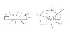
- FIG. 5shows a simplified cross section through a top cover with a ground lug of a second embodiment according to the invention
- FIG. 6shows a detail of a simplified top view of the second embodiment, namely a ground lug extending through a hole of a top cover;
- FIG. 7shows a detail similar to FIG. 6 , namely the top cover at the hole without ground lug.
- a tuner housing according to the inventionwhich is shown in the FIGS. 1 and 2 comprises a support, namely a frame, and two cover parts, namely a top cover and a bottom cover.
- the tuner housingfurther comprises a HF connector 1 and numerous connection pins 2 .
- the top cover and the bottom coverare attached to the frame which comprises four side walls 3 .
- the attachment of the top and bottom cover to the frameis generated as a clamped connection with a certain clamping force 4 in a direction perpendicular to the side walls 3 .
- the framecarries electronic equipment, in particular a printed circuit board with tuner circuitry.
- the electronic equipmentis arranged inside of the tuner housing and is not visible in the figures.
- the top covercomprises a cover wall, namely a top wall 5 , covering the electronic equipment and at least two clamping elements 6 which are arranged at opposite sides of the top wall 5 and bent off from the top wall 5 in direction to the corresponding side walls 3 of the frame.
- the bottom covercomprises a cover wall, namely a bottom wall 7 , covering the back side of the printed circuit board and at least two clamping elements 8 which are arranged at opposite sides of the bottom wall 7 and bent off from the bottom wall 7 in direction to the corresponding side walls 3 of the frame.
- Each clamping element 6 , 8comprises an outward bent end part 9 , 10 . Due to their shape the clamping elements 6 , 8 are pressed to the side walls 3 generating the clamping force 4 . They are in a resilient contact with the side walls 3 .
- the top covercomprises four clamping elements 6 which each extends over one of the four side walls 3 .
- the bottom coveralso comprises four clamping elements 8 of which each extends over one of the four side walls 4 .
- the clamping elements 6 , 8contact the frame at an essential part of its circumference.
- the framealso comprises four ground lugs 11 , which are shown in the FIGS. 1 and 2 .
- FIGS. 3 and 4show a region of a ground lug 11 in detail wherein FIG. 3 shows a top view and FIG. 4 a cross section.
- Each ground lug 11extends through a hole 12 of the top wall 5 of the top cover parallel to the side walls 3 of the frame. As the clamping force of the clamped connection between the top cover and the frame acts in the direction perpendicular to the side walls it also acts in the direction perpendicular to the elongation of the ground lugs 11 .
- Each ground lug 11has an inner section with a greater width in the region of the hole 12 and an outer section with a less width above this region. This is shown in FIG. 2 .
- the top wall 5is provided with a projection for each ground lug 11 which projects into the hole 12 and contacts the ground lug 11 .
- the projectionsare arranged in a way that each projection contacts the corresponding ground lug 9 opposite to the clamping force 3 .
- Each ground lug 11is arranged at the border of the top wall 5 in the region of a clamping element 6 .
- the corresponding projectioncontacts the ground lug 11 on its inner face with a contact force 13 opposite to the clamping element 6 and opposite to the clamping force 3 .
- the projectionis generated in a preferred embodiment as three teeth 14 .
- Each tooth 14has the shape of a triangle, where the angle ⁇ of the top of the triangle is between 80 and 100°, e.g. 90°.
- top cover and the bottom covercomprise numerous clamping elements 6 , 8 distributed over the side walls 3 of the frame.
- the tuner housingnamely the frame and the top and bottom cover are manufactured by a metal.
- the length of the tuner housing without HF connector 1is e.g. about 50 mm, its width about 35 mm and its height about 10 mm.
- the length of each hole 12is about 3.5 mm and its width about 2 mm.
- the width of the ground lug 11 which corresponds to the thickness of the side walls 3is about 0.8 mm.
- the deepness of the teeth 14is about 0.3 mm and represented in FIG. 7 by two lines projecting out of the detail circle.
- the thickness of the clamping element 6 which corresponds to the thickness of the top wall 5is less or about 0.3 mm and is indicated in FIG. 7 by two parallel double lines crossing the hole 12 .
- the clamping forceis such that the teeth 14 are scratched into the ground lug 11 , when attaching the top cover.
- FIGS. 5 to 7corresponds to the first embodiment except of the following features:
- the side walls 3comprise at least one bulge 15 for each clamping element 6 , 8 , wherein the end part 9 , 10 is located next to the bulge 15 opposite to the top and the bottom wall 5 , 7 , respectively.
- the top wall 5is provided with a step 16 in direction to the side walls 3 , wherein the holes 12 with the ground lugs 11 are arranged between the step 16 and the border of the top wall 5 .
Landscapes
- Engineering & Computer Science (AREA)
- Microelectronics & Electronic Packaging (AREA)
- Signal Processing (AREA)
- Shielding Devices Or Components To Electric Or Magnetic Fields (AREA)
- Structure Of Receivers (AREA)
Abstract
Description
Claims (9)
Applications Claiming Priority (4)
| Application Number | Priority Date | Filing Date | Title |
|---|---|---|---|
| EP07301543.0 | 2007-11-12 | ||
| EP07301543 | 2007-11-12 | ||
| EP07301543 | 2007-11-12 | ||
| PCT/EP2008/064573WO2009062842A1 (en) | 2007-11-12 | 2008-10-28 | Tuner housing |
Publications (2)
| Publication Number | Publication Date |
|---|---|
| US20100270068A1 US20100270068A1 (en) | 2010-10-28 |
| US8242361B2true US8242361B2 (en) | 2012-08-14 |
Family
ID=40251713
Family Applications (1)
| Application Number | Title | Priority Date | Filing Date |
|---|---|---|---|
| US12/734,592Active2029-07-31US8242361B2 (en) | 2007-11-12 | 2008-10-28 | Tuner housing |
Country Status (7)
| Country | Link |
|---|---|
| US (1) | US8242361B2 (en) |
| EP (1) | EP2208408B1 (en) |
| JP (1) | JP5386500B2 (en) |
| CN (1) | CN101855954B (en) |
| ES (1) | ES2386751T3 (en) |
| PL (1) | PL2208408T3 (en) |
| WO (1) | WO2009062842A1 (en) |
Families Citing this family (1)
| Publication number | Priority date | Publication date | Assignee | Title |
|---|---|---|---|---|
| US8747121B1 (en) | 2013-01-24 | 2014-06-10 | Cresta Technology Corporation | Television tuner module having a shielded housing mounted on an outer circuit board and having an inner circuit board with a tuner chip |
Citations (17)
| Publication number | Priority date | Publication date | Assignee | Title |
|---|---|---|---|---|
| US3816911A (en)* | 1971-10-01 | 1974-06-18 | Motorola Inc | Shielding techniques for r.f. circuitry |
| DE3233621C1 (en) | 1982-09-10 | 1984-01-19 | Standard Elektrik Lorenz Ag, 7000 Stuttgart | Screening housing having a cover and/or base which can be placed on |
| US4628412A (en)* | 1983-12-12 | 1986-12-09 | Alps Electric Co., Ltd. | Case for shielding electronic devices |
| DE3629913A1 (en) | 1986-09-03 | 1988-03-17 | Standard Elektrik Lorenz Ag | Screening housing |
| US4747019A (en)* | 1984-12-14 | 1988-05-24 | Murata Manufacturing Co., Ltd. | Feedthrough capacitor arrangement |
| US4754101A (en)* | 1986-10-23 | 1988-06-28 | Instrument Specialties Co., Inc. | Electromagnetic shield for printed circuit board |
| US4816613A (en)* | 1986-12-25 | 1989-03-28 | Murata Manufacturing Co., Ltd. | Electrical shielding case |
| DE3922461A1 (en) | 1988-07-08 | 1990-01-11 | Alps Electric Co Ltd | ARRANGEMENT OF A SHIELDING HOUSING AND A COVER |
| JPH0278296A (en) | 1988-09-14 | 1990-03-19 | Hitachi Ltd | Electromagnetic shielding device of electronic equipment casing |
| US5608188A (en)* | 1994-09-02 | 1997-03-04 | Motorola, Inc. | Multi compartment electromagnetic energy shield |
| WO1997046064A1 (en) | 1996-05-31 | 1997-12-04 | Knürr-Mechanik für die Elektronik Aktiengesellschaft | Housing |
| US5704117A (en)* | 1995-06-08 | 1998-01-06 | Northern Telecom Limited | Method of assembling an EMI shield around an electronic component |
| US6144557A (en)* | 1999-04-09 | 2000-11-07 | Lucent Technologies, Inc. | Self-locking conductive pin for printed wiring substrate electronics case |
| US6339535B1 (en)* | 1997-03-27 | 2002-01-15 | Siemens Aktiengesellschaft | Device for fastening a protective coverplate |
| US6593523B2 (en)* | 2001-01-19 | 2003-07-15 | Mitsubishi Denki Kabushiki Kaisha | Shield structure for electronic circuit parts |
| EP1381264A1 (en) | 2001-03-29 | 2004-01-14 | Sanyo Electric Co., Ltd. | Shield case |
| US6930891B1 (en)* | 1999-09-10 | 2005-08-16 | Sony Computer Entertainment Inc. | Electromagnetic shielding plate, electromagnetic shielding structure, and entertainment system |
Family Cites Families (6)
| Publication number | Priority date | Publication date | Assignee | Title |
|---|---|---|---|---|
| JPS6099584U (en)* | 1983-12-12 | 1985-07-06 | アルプス電気株式会社 | Small case for electronic equipment |
| JPS63124795U (en)* | 1987-02-04 | 1988-08-15 | ||
| JPH0726874Y2 (en)* | 1988-06-13 | 1995-06-14 | ミツミ電機株式会社 | Circuit board device for tuner |
| JPH0666092U (en)* | 1993-02-26 | 1994-09-16 | ミツミ電機株式会社 | Shield case |
| JPH09307258A (en)* | 1996-05-13 | 1997-11-28 | Alps Electric Co Ltd | Shielding case of high-frequency equipment |
| JPH1022674A (en)* | 1996-06-28 | 1998-01-23 | Sharp Corp | Tuner structure |
- 2008
- 2008-10-28ESES08849312Tpatent/ES2386751T3/enactiveActive
- 2008-10-28WOPCT/EP2008/064573patent/WO2009062842A1/enactiveApplication Filing
- 2008-10-28PLPL08849312Tpatent/PL2208408T3/enunknown
- 2008-10-28USUS12/734,592patent/US8242361B2/enactiveActive
- 2008-10-28CNCN2008801155676Apatent/CN101855954B/enactiveActive
- 2008-10-28EPEP08849312Apatent/EP2208408B1/enactiveActive
- 2008-10-28JPJP2010532544Apatent/JP5386500B2/ennot_activeExpired - Fee Related
Patent Citations (18)
| Publication number | Priority date | Publication date | Assignee | Title |
|---|---|---|---|---|
| US3816911A (en)* | 1971-10-01 | 1974-06-18 | Motorola Inc | Shielding techniques for r.f. circuitry |
| DE3233621C1 (en) | 1982-09-10 | 1984-01-19 | Standard Elektrik Lorenz Ag, 7000 Stuttgart | Screening housing having a cover and/or base which can be placed on |
| US4628412A (en)* | 1983-12-12 | 1986-12-09 | Alps Electric Co., Ltd. | Case for shielding electronic devices |
| US4747019A (en)* | 1984-12-14 | 1988-05-24 | Murata Manufacturing Co., Ltd. | Feedthrough capacitor arrangement |
| DE3629913A1 (en) | 1986-09-03 | 1988-03-17 | Standard Elektrik Lorenz Ag | Screening housing |
| US4754101A (en)* | 1986-10-23 | 1988-06-28 | Instrument Specialties Co., Inc. | Electromagnetic shield for printed circuit board |
| US4816613A (en)* | 1986-12-25 | 1989-03-28 | Murata Manufacturing Co., Ltd. | Electrical shielding case |
| US4948923A (en) | 1988-07-08 | 1990-08-14 | Alps Electric Co., Ltd. | Bottom cover installation structure of a shield case |
| DE3922461A1 (en) | 1988-07-08 | 1990-01-11 | Alps Electric Co Ltd | ARRANGEMENT OF A SHIELDING HOUSING AND A COVER |
| JPH0278296A (en) | 1988-09-14 | 1990-03-19 | Hitachi Ltd | Electromagnetic shielding device of electronic equipment casing |
| US5608188A (en)* | 1994-09-02 | 1997-03-04 | Motorola, Inc. | Multi compartment electromagnetic energy shield |
| US5704117A (en)* | 1995-06-08 | 1998-01-06 | Northern Telecom Limited | Method of assembling an EMI shield around an electronic component |
| WO1997046064A1 (en) | 1996-05-31 | 1997-12-04 | Knürr-Mechanik für die Elektronik Aktiengesellschaft | Housing |
| US6339535B1 (en)* | 1997-03-27 | 2002-01-15 | Siemens Aktiengesellschaft | Device for fastening a protective coverplate |
| US6144557A (en)* | 1999-04-09 | 2000-11-07 | Lucent Technologies, Inc. | Self-locking conductive pin for printed wiring substrate electronics case |
| US6930891B1 (en)* | 1999-09-10 | 2005-08-16 | Sony Computer Entertainment Inc. | Electromagnetic shielding plate, electromagnetic shielding structure, and entertainment system |
| US6593523B2 (en)* | 2001-01-19 | 2003-07-15 | Mitsubishi Denki Kabushiki Kaisha | Shield structure for electronic circuit parts |
| EP1381264A1 (en) | 2001-03-29 | 2004-01-14 | Sanyo Electric Co., Ltd. | Shield case |
Also Published As
| Publication number | Publication date |
|---|---|
| EP2208408A1 (en) | 2010-07-21 |
| WO2009062842A1 (en) | 2009-05-22 |
| CN101855954B (en) | 2012-05-30 |
| JP5386500B2 (en) | 2014-01-15 |
| EP2208408B1 (en) | 2012-06-27 |
| US20100270068A1 (en) | 2010-10-28 |
| CN101855954A (en) | 2010-10-06 |
| PL2208408T3 (en) | 2012-10-31 |
| ES2386751T3 (en) | 2012-08-29 |
| JP2011503859A (en) | 2011-01-27 |
Similar Documents
| Publication | Publication Date | Title |
|---|---|---|
| US6560124B1 (en) | Display device with plasma display panel | |
| US8520405B2 (en) | Shield case and image display device | |
| JP2006522485A (en) | Shield cage with multiple module bays | |
| KR101953772B1 (en) | Tuner module and reception device | |
| US20090268420A1 (en) | Shielding assembly | |
| JP2013140755A (en) | Receptacle connector and shield connector | |
| US8242361B2 (en) | Tuner housing | |
| US6619984B2 (en) | Electrical connector having improved shielding | |
| US7059875B2 (en) | Ground metal fitting and ground structure for jacks of electronic devices | |
| KR101450306B1 (en) | Grounding spring | |
| CN108513522B (en) | Assembly component and assembly method thereof | |
| US7247053B2 (en) | High-frequency apparatus having high performance and capable of preventing entry of interfering wave into terminal | |
| KR20120026963A (en) | High-frequency module | |
| EP2458953B1 (en) | Electronic device | |
| KR200183048Y1 (en) | Crt grounding device of display | |
| KR100916272B1 (en) | Tuner Chassis | |
| JP2009266907A (en) | Tuner unit and electromagnetic wave shield structure of analog digital composite machine | |
| JPH057822Y2 (en) | ||
| US20130063906A1 (en) | Circuit board assembly and electronic device with circuit board | |
| JP2012147321A (en) | Module with connector | |
| JP2012119514A (en) | Shield case structure, tuner device and receiving apparatus | |
| JP2003258453A (en) | Fixing structure of printed board | |
| JP2009099794A (en) | Electronic circuit unit | |
| JPH058705Y2 (en) | ||
| JP2018116983A (en) | Electronics |
Legal Events
| Date | Code | Title | Description |
|---|---|---|---|
| AS | Assignment | Owner name:THOMSON LICENSING, FRANCE Free format text:ASSIGNMENT OF ASSIGNORS INTEREST;ASSIGNORS:PANG, KIM SUAN;LUM, LYE YOONG;LEONG, KOK KEEN;SIGNING DATES FROM 20100422 TO 20100427;REEL/FRAME:024385/0021 | |
| STCF | Information on status: patent grant | Free format text:PATENTED CASE | |
| FPAY | Fee payment | Year of fee payment:4 | |
| AS | Assignment | Owner name:INTERDIGITAL CE PATENT HOLDINGS, FRANCE Free format text:ASSIGNMENT OF ASSIGNORS INTEREST;ASSIGNOR:THOMSON LICENSING;REEL/FRAME:047332/0511 Effective date:20180730 | |
| MAFP | Maintenance fee payment | Free format text:PAYMENT OF MAINTENANCE FEE, 8TH YEAR, LARGE ENTITY (ORIGINAL EVENT CODE: M1552); ENTITY STATUS OF PATENT OWNER: LARGE ENTITY Year of fee payment:8 | |
| MAFP | Maintenance fee payment | Free format text:PAYMENT OF MAINTENANCE FEE, 12TH YEAR, LARGE ENTITY (ORIGINAL EVENT CODE: M1553); ENTITY STATUS OF PATENT OWNER: LARGE ENTITY Year of fee payment:12 | |
| AS | Assignment | Owner name:INTERDIGITAL CE PATENT HOLDINGS, SAS, FRANCE Free format text:CORRECTIVE ASSIGNMENT TO CORRECT THE RECEIVING PARTY NAME FROM INTERDIGITAL CE PATENT HOLDINGS TO INTERDIGITAL CE PATENT HOLDINGS, SAS. PREVIOUSLY RECORDED AT REEL: 47332 FRAME: 511. ASSIGNOR(S) HEREBY CONFIRMS THE ASSIGNMENT;ASSIGNOR:THOMSON LICENSING;REEL/FRAME:066703/0509 Effective date:20180730 |