US8242350B2 - Concentrating photovoltaic solar panel - Google Patents
Concentrating photovoltaic solar panelDownload PDFInfo
- Publication number
- US8242350B2 US8242350B2US12/454,321US45432109AUS8242350B2US 8242350 B2US8242350 B2US 8242350B2US 45432109 AUS45432109 AUS 45432109AUS 8242350 B2US8242350 B2US 8242350B2
- Authority
- US
- United States
- Prior art keywords
- photovoltaic
- concentrator
- bucket
- modules
- chassis
- Prior art date
- Legal status (The legal status is an assumption and is not a legal conclusion. Google has not performed a legal analysis and makes no representation as to the accuracy of the status listed.)
- Expired - Fee Related, expires
Links
- 230000007246mechanismEffects0.000claimsabstractdescription54
- 239000000463materialSubstances0.000claimsdescription34
- 239000003677Sheet moulding compoundSubstances0.000claimsdescription13
- 244000261422Lysimachia clethroidesSpecies0.000claimsdescription8
- 239000004412Bulk moulding compoundSubstances0.000claimsdescription6
- 239000004593EpoxySubstances0.000claimsdescription5
- 239000012298atmosphereSubstances0.000claimsdescription2
- 239000012528membraneSubstances0.000claimsdescription2
- 239000002991molded plasticSubstances0.000claims1
- 238000000034methodMethods0.000abstractdescription15
- 238000005452bendingMethods0.000abstractdescription4
- 239000000853adhesiveSubstances0.000description27
- 230000001070adhesive effectEffects0.000description27
- 230000033001locomotionEffects0.000description26
- 230000003287optical effectEffects0.000description24
- 238000005286illuminationMethods0.000description18
- 238000009434installationMethods0.000description16
- 229910052751metalInorganic materials0.000description16
- 239000002184metalSubstances0.000description16
- 230000005484gravityEffects0.000description15
- 230000000712assemblyEffects0.000description14
- 238000000429assemblyMethods0.000description14
- 238000013459approachMethods0.000description13
- 238000004519manufacturing processMethods0.000description11
- 230000006870functionEffects0.000description10
- 229910052782aluminiumInorganic materials0.000description9
- XAGFODPZIPBFFR-UHFFFAOYSA-NaluminiumChemical compound[Al]XAGFODPZIPBFFR-UHFFFAOYSA-N0.000description9
- 230000008901benefitEffects0.000description9
- 238000003756stirringMethods0.000description8
- 229920001187thermosetting polymerPolymers0.000description8
- 239000004033plasticSubstances0.000description6
- 238000000576coating methodMethods0.000description5
- 230000005611electricityEffects0.000description5
- 239000000203mixtureSubstances0.000description5
- 238000000465mouldingMethods0.000description5
- 238000012856packingMethods0.000description5
- 239000000758substrateSubstances0.000description5
- 238000003466weldingMethods0.000description5
- RYGMFSIKBFXOCR-UHFFFAOYSA-NCopperChemical compound[Cu]RYGMFSIKBFXOCR-UHFFFAOYSA-N0.000description4
- 239000011248coating agentSubstances0.000description4
- 229910052802copperInorganic materials0.000description4
- 239000010949copperSubstances0.000description4
- 230000000694effectsEffects0.000description4
- 230000005855radiationEffects0.000description4
- 239000000243solutionSubstances0.000description4
- XLYOFNOQVPJJNP-UHFFFAOYSA-NwaterSubstancesOXLYOFNOQVPJJNP-UHFFFAOYSA-N0.000description4
- 230000009471actionEffects0.000description3
- 239000012141concentrateSubstances0.000description3
- 238000010438heat treatmentMethods0.000description3
- 230000013011matingEffects0.000description3
- 230000009467reductionEffects0.000description3
- 239000003351stiffenerSubstances0.000description3
- 229910001369BrassInorganic materials0.000description2
- 239000010951brassSubstances0.000description2
- 239000003054catalystSubstances0.000description2
- 239000000919ceramicSubstances0.000description2
- 150000001875compoundsChemical class0.000description2
- 238000009833condensationMethods0.000description2
- 230000005494condensationEffects0.000description2
- 230000003750conditioning effectEffects0.000description2
- 238000011109contaminationMethods0.000description2
- 238000013461designMethods0.000description2
- 238000010586diagramMethods0.000description2
- 229920000295expanded polytetrafluoroethylenePolymers0.000description2
- 239000011152fibreglassSubstances0.000description2
- 239000000945fillerSubstances0.000description2
- 238000009432framingMethods0.000description2
- 239000003365glass fiberSubstances0.000description2
- 238000000265homogenisationMethods0.000description2
- 238000003384imaging methodMethods0.000description2
- 230000003116impacting effectEffects0.000description2
- 239000007788liquidSubstances0.000description2
- 150000002739metalsChemical class0.000description2
- 229920000642polymerPolymers0.000description2
- 238000000926separation methodMethods0.000description2
- FRWYFWZENXDZMU-UHFFFAOYSA-N2-iodoquinolineChemical compoundC1=CC=CC2=NC(I)=CC=C21FRWYFWZENXDZMU-UHFFFAOYSA-N0.000description1
- 229920000544Gore-TexPolymers0.000description1
- 235000014676Phragmites communisNutrition0.000description1
- XUIMIQQOPSSXEZ-UHFFFAOYSA-NSiliconChemical compound[Si]XUIMIQQOPSSXEZ-UHFFFAOYSA-N0.000description1
- 239000004775TyvekSubstances0.000description1
- 229920000690TyvekPolymers0.000description1
- 230000001133accelerationEffects0.000description1
- NIXOWILDQLNWCW-UHFFFAOYSA-Nacrylic acid groupChemical groupC(C=C)(=O)ONIXOWILDQLNWCW-UHFFFAOYSA-N0.000description1
- PNEYBMLMFCGWSK-UHFFFAOYSA-Naluminium oxideInorganic materials[O-2].[O-2].[O-2].[Al+3].[Al+3]PNEYBMLMFCGWSK-UHFFFAOYSA-N0.000description1
- 239000006117anti-reflective coatingSubstances0.000description1
- 238000003491arrayMethods0.000description1
- LTPBRCUWZOMYOC-UHFFFAOYSA-Nberyllium oxideInorganic materialsO=[Be]LTPBRCUWZOMYOC-UHFFFAOYSA-N0.000description1
- 230000005540biological transmissionEffects0.000description1
- 230000000903blocking effectEffects0.000description1
- 230000015556catabolic processEffects0.000description1
- 229910010293ceramic materialInorganic materials0.000description1
- 239000003795chemical substances by applicationSubstances0.000description1
- 239000004020conductorSubstances0.000description1
- 238000010276constructionMethods0.000description1
- 239000000356contaminantSubstances0.000description1
- 230000008602contractionEffects0.000description1
- PMHQVHHXPFUNSP-UHFFFAOYSA-Mcopper(1+);methylsulfanylmethane;bromideChemical compoundBr[Cu].CSCPMHQVHHXPFUNSP-UHFFFAOYSA-M0.000description1
- 230000008878couplingEffects0.000description1
- 238000010168coupling processMethods0.000description1
- 238000005859coupling reactionMethods0.000description1
- 238000006731degradation reactionMethods0.000description1
- 238000011161developmentMethods0.000description1
- 239000000428dustSubstances0.000description1
- 238000009429electrical wiringMethods0.000description1
- 239000012777electrically insulating materialSubstances0.000description1
- 230000008030eliminationEffects0.000description1
- 238000003379elimination reactionMethods0.000description1
- 239000008393encapsulating agentSubstances0.000description1
- 230000006353environmental stressEffects0.000description1
- 238000004880explosionMethods0.000description1
- 230000005669field effectEffects0.000description1
- 239000006260foamSubstances0.000description1
- -1for exampleSubstances0.000description1
- 238000009472formulationMethods0.000description1
- 239000011521glassSubstances0.000description1
- 230000006872improvementEffects0.000description1
- 238000002347injectionMethods0.000description1
- 239000007924injectionSubstances0.000description1
- 238000002955isolationMethods0.000description1
- 230000007774longtermEffects0.000description1
- 238000012423maintenanceMethods0.000description1
- 230000035800maturationEffects0.000description1
- 238000012986modificationMethods0.000description1
- 230000004048modificationEffects0.000description1
- 239000006082mold release agentSubstances0.000description1
- 238000010943off-gassingMethods0.000description1
- 239000002245particleSubstances0.000description1
- 239000000049pigmentSubstances0.000description1
- 239000000088plastic resinSubstances0.000description1
- 229920001296polysiloxanePolymers0.000description1
- 230000008569processEffects0.000description1
- 238000002310reflectometryMethods0.000description1
- 238000011160researchMethods0.000description1
- 238000009420retrofittingMethods0.000description1
- 238000010079rubber tappingMethods0.000description1
- 238000007665saggingMethods0.000description1
- 239000000565sealantSubstances0.000description1
- 239000004065semiconductorSubstances0.000description1
- 230000035939shockEffects0.000description1
- 229910052710siliconInorganic materials0.000description1
- 239000010703siliconSubstances0.000description1
- 239000007787solidSubstances0.000description1
- 239000003381stabilizerSubstances0.000description1
- 229910001220stainless steelInorganic materials0.000description1
- 239000010935stainless steelSubstances0.000description1
- 230000035882stressEffects0.000description1
- 239000004634thermosetting polymerSubstances0.000description1
- 238000012546transferMethods0.000description1
- 230000007704transitionEffects0.000description1
- 238000013519translationMethods0.000description1
Images


Classifications
- F—MECHANICAL ENGINEERING; LIGHTING; HEATING; WEAPONS; BLASTING
- F24—HEATING; RANGES; VENTILATING
- F24S—SOLAR HEAT COLLECTORS; SOLAR HEAT SYSTEMS
- F24S30/00—Arrangements for moving or orienting solar heat collector modules
- F24S30/40—Arrangements for moving or orienting solar heat collector modules for rotary movement
- F24S30/45—Arrangements for moving or orienting solar heat collector modules for rotary movement with two rotation axes
- F24S30/455—Horizontal primary axis
- H—ELECTRICITY
- H10—SEMICONDUCTOR DEVICES; ELECTRIC SOLID-STATE DEVICES NOT OTHERWISE PROVIDED FOR
- H10F—INORGANIC SEMICONDUCTOR DEVICES SENSITIVE TO INFRARED RADIATION, LIGHT, ELECTROMAGNETIC RADIATION OF SHORTER WAVELENGTH OR CORPUSCULAR RADIATION
- H10F77/00—Constructional details of devices covered by this subclass
- H10F77/40—Optical elements or arrangements
- H10F77/42—Optical elements or arrangements directly associated or integrated with photovoltaic cells, e.g. light-reflecting means or light-concentrating means
- H10F77/484—Refractive light-concentrating means, e.g. lenses
- H—ELECTRICITY
- H10—SEMICONDUCTOR DEVICES; ELECTRIC SOLID-STATE DEVICES NOT OTHERWISE PROVIDED FOR
- H10F—INORGANIC SEMICONDUCTOR DEVICES SENSITIVE TO INFRARED RADIATION, LIGHT, ELECTROMAGNETIC RADIATION OF SHORTER WAVELENGTH OR CORPUSCULAR RADIATION
- H10F77/00—Constructional details of devices covered by this subclass
- H10F77/40—Optical elements or arrangements
- H10F77/42—Optical elements or arrangements directly associated or integrated with photovoltaic cells, e.g. light-reflecting means or light-concentrating means
- H10F77/488—Reflecting light-concentrating means, e.g. parabolic mirrors or concentrators using total internal reflection
- H—ELECTRICITY
- H10—SEMICONDUCTOR DEVICES; ELECTRIC SOLID-STATE DEVICES NOT OTHERWISE PROVIDED FOR
- H10F—INORGANIC SEMICONDUCTOR DEVICES SENSITIVE TO INFRARED RADIATION, LIGHT, ELECTROMAGNETIC RADIATION OF SHORTER WAVELENGTH OR CORPUSCULAR RADIATION
- H10F77/00—Constructional details of devices covered by this subclass
- H10F77/60—Arrangements for cooling, heating, ventilating or compensating for temperature fluctuations
- H10F77/63—Arrangements for cooling directly associated or integrated with photovoltaic cells, e.g. heat sinks directly associated with the photovoltaic cells or integrated Peltier elements for active cooling
- F—MECHANICAL ENGINEERING; LIGHTING; HEATING; WEAPONS; BLASTING
- F24—HEATING; RANGES; VENTILATING
- F24S—SOLAR HEAT COLLECTORS; SOLAR HEAT SYSTEMS
- F24S23/00—Arrangements for concentrating solar-rays for solar heat collectors
- F24S23/30—Arrangements for concentrating solar-rays for solar heat collectors with lenses
- Y—GENERAL TAGGING OF NEW TECHNOLOGICAL DEVELOPMENTS; GENERAL TAGGING OF CROSS-SECTIONAL TECHNOLOGIES SPANNING OVER SEVERAL SECTIONS OF THE IPC; TECHNICAL SUBJECTS COVERED BY FORMER USPC CROSS-REFERENCE ART COLLECTIONS [XRACs] AND DIGESTS
- Y02—TECHNOLOGIES OR APPLICATIONS FOR MITIGATION OR ADAPTATION AGAINST CLIMATE CHANGE
- Y02E—REDUCTION OF GREENHOUSE GAS [GHG] EMISSIONS, RELATED TO ENERGY GENERATION, TRANSMISSION OR DISTRIBUTION
- Y02E10/00—Energy generation through renewable energy sources
- Y02E10/40—Solar thermal energy, e.g. solar towers
- Y02E10/47—Mountings or tracking
- Y—GENERAL TAGGING OF NEW TECHNOLOGICAL DEVELOPMENTS; GENERAL TAGGING OF CROSS-SECTIONAL TECHNOLOGIES SPANNING OVER SEVERAL SECTIONS OF THE IPC; TECHNICAL SUBJECTS COVERED BY FORMER USPC CROSS-REFERENCE ART COLLECTIONS [XRACs] AND DIGESTS
- Y02—TECHNOLOGIES OR APPLICATIONS FOR MITIGATION OR ADAPTATION AGAINST CLIMATE CHANGE
- Y02E—REDUCTION OF GREENHOUSE GAS [GHG] EMISSIONS, RELATED TO ENERGY GENERATION, TRANSMISSION OR DISTRIBUTION
- Y02E10/00—Energy generation through renewable energy sources
- Y02E10/50—Photovoltaic [PV] energy
- Y02E10/52—PV systems with concentrators
Definitions
- the present inventionrelates to photovoltaic power systems, photovoltaic concentrator modules, and related devices and methods.
- Solar panelsare generally well known (see, e.g., U.S. Pub. No. 2006/0283497 (Hines)). It is desirable to produce solar panels that either produce more power and/or that cost less.
- photovoltaic solar concentratorshave generally taken one of two approaches—either build a large reflective trough or dish or a field of articulating mirrors which reflect light to a central point, where it is converted to power (such as by Solar Systems of Victoria, Australia and by Gross et al., U.S. Pat. No. 2005/0034751), or tightly pack a large number of small concentrators into a large panel which articulates rigidly to follow the sun (such as by Chen, U.S. Pub. No. 2003/0075212 or Stewart, U.S. Pub. No. 2005/0081908). See also the Matlock et al. reference (U.S. Pat. No. 4,000,734), which discloses elongated reflectors mounted for movement around a heating tube arranged in the linear focus of the reflectors and a tracking mechanism.
- a recent variation on this approachis to place two rows of collectors in a frame where they articulate approximately in place, such as in Fukuda, U.S. Pat. No. 6.079,408.
- Such an approachpackages a tracking concentrator into a form that is approximately flat.
- Framing around the perimeter of a solar panelcan limit packing density of solar panels and/or make the panels less aesthetically pleasing.
- sparse packingcan make it easier for concentrator modules to operate without shading each other through a larger portion of the day and of the year, allowing a cost-effective use of the individual concentrators by increasing their overall daily exposure to sunlight.
- a technical challenge with respect to developing innovative solutions around articulating concentrator modulesis that many mounting locations such as rooftops and the like tend to have uneven surfaces which can cause the concentrators to bind to an undue degree when the modules articulate in tilt and/or tilt.
- one or more attachment pointscan be positioned in the interior region of a concentrator module such that a tip articulating mechanism can articulate the concentrator module substantially about the center of gravity of the photovoltaic concentrator module.
- Such attachment pointscan also permit the concentrator module to articulate in tilt.
- Having attachment points in the interior region of a concentrator modulepermits the panel to not have framing around the perimeter of the panel.
- Support structurecan be positioned underneath the concentrator modules.
- two or more such concentrator modulescan be packed relatively more tightly than in many traditional ground-based, utility-scale solar concentrator arrays.
- Packing concentrator modulesmore tightly tends to better amortize the costs associated with planning, permitting, and executing the installation of a photovoltaic array based on the concentrator systems, especially, for example, for a commercial rooftop installation, potentially leading to a lower overall cost of energy produced by the system. Nonetheless, it can be desirable to leave at least some amount of space between the individual concentrators.
- Another innovationincludes an articulation chassis having an articulating member rigidly and physically coupled to one or more other chassis members directly attached to concentrator modules in a manner that substantially isolates or minimizes any bending and the like from being transferred from the driven articulating member (e.g., the axle).
- the driven articulating membere.g., the axle
- the articulation chassis memberscan be positioned beneath the concentrator modules so that the panel essentially does not have a frame around the perimeter of the panel.
- many preferred embodimentsdo not include a frame along one or more sides of the unit (e.g., no frame around the perimeter of the panel), instead making use of the unit's concentrator articulation mechanism to also provide structural support, allowing a more cost-effective unit via elimination of unnecessary frame components.
- the support structurecan be tucked underneath the concentrating solar panel yet still be capable of articulating the concentrator module(s) substantially about the center of gravity of each concentrator module, thereby allowing support of the concentrator modules without increasing the width of the solar panel, helping to improve the efficiency of the solar panel.
- Another innovationincludes a solar panel having adjustable mounting structure so as to accommodate a plurality of mounting locations.
- Such mounting structureadvantageously permits traditional solar panel mounting hardware (e.g., rails, etc.) to accommodate one or more new and unique solar panel designs.
- Another innovationincludes a solar panel having mounting hardware with a suitable number of degrees of freedom so as to prevent undue binding when the concentrator modules articulate in tilt and/or tip.
- mounting hardwarepermits a given solar panel design to adapt to a broad range of mounting surfaces/locations (e.g., relatively uneven rooftop surfaces and the like) and articulate in tilt and/or tilt in a robust manner without undue binding of the concentrator modules.
- adjustable mounting structureand having suitable degrees of freedom are important breakthroughs, because they can allow concentrating solar panels, with heretofore unseen higher efficiencies and also with lower costs, to penetrate markets currently dominated by traditional flat-panel solar, especially the commercial rooftop market, greatly reducing cost and increasing the acceleration of deployment of solar into the market.
- thisallows current flat-panel solar installers to use much of their existing mounting hardware and installation techniques, and even sales and marketing techniques, to deploy concentrating solar.
- the inventioncombines the advantages (e.g., cost advantages) of concentrating solar with the market acceptance and form factor advantages of traditional flat photovoltaic panels.
- Another innovative solutionincludes one or more mechanical support structures/braces (e.g., a housing) that rigidly couple one or more concentrating secondary optics to a concentrator module (e.g., to a heat sink assembly of the module).
- a mechanical support structure/bracese.g., a housing
- concentrating secondary opticse.g., to a heat sink assembly of the module.
- a photovoltaic concentrator moduleincludes a main body portion having a base; one or more side walls connected to the base; one or more attachment points positioned in the interior region of the main body portion; and one or more apertures located opposite the base.
- the base and the one or more sidewallshelp define an interior region of the main body portion.
- the one or more attachment pointscan couple the main body portion to a tip articulating mechanism such that the tip articulating mechanism can articulate the photovoltaic concentrator module substantially about the center of gravity of the photovoltaic concentrator module.
- a photovoltaic power systemincludes a tip articulating mechanism and a plurality of photovoltaic concentrator modules.
- Each photovoltaic concentrator moduleincludes a main body portion having a base; one or more side walls connected to the base; one or more attachment points positioned in the interior region of the main body portion; and one or more apertures located opposite the base.
- the base and the one or more sidewallshelp define an interior region of the main body portion.
- the one or more attachment pointsare coupled to the tip articulating mechanism such that the tip articulating mechanism can articulate the photovoltaic concentrator module substantially about the center of gravity of the photovoltaic concentrator module.
- a photovoltaic power systemincludes a tip articulation mechanism and a plurality of photovoltaic concentrator modules.
- the plurality of photovoltaic concentrator modulesare positioned adjacent to each other in a linear manner.
- the plurality of photovoltaic concentrator modulesdefine an inboard region.
- Each photovoltaic concentrator moduleincludes one or more attachment points positioned in the inboard region.
- the one or more attachment pointsare each coupled to the tip articulating mechanism such that the tip articulating mechanism can articulate each photovoltaic concentrator module substantially about the center of gravity of the photovoltaic concentrator module.
- a photovoltaic concentrator moduleincludes an inboard region and one or more attachment points positioned in the inboard region.
- the one or more attachment pointscan be coupled to a tip articulating mechanism such that the tip articulating mechanism can articulate the photovoltaic concentrator module substantially about the center of gravity of the photovoltaic concentrator module.
- a photovoltaic power systemincludes a plurality of articulating photovoltaic concentrator modules positioned so as to define a panel of photovoltaic concentrator modules and an articulating mechanism coupled to each photovoltaic concentrator module.
- the paneldefines a footprint having a first dimension and a second dimension.
- the articulating mechanismincludes at least three chassis members. Each chassis member is substantially parallel to the other chassis members and each chassis member extends along the first dimension of the panel footprint. At least two chassis members are physically coupled to each photovoltaic concentrator modules in an articulating manner. Each of the two chassis members are rigidly, physically coupled to the third chassis member at two or more points.
- a photovoltaic power systemincludes a plurality of articulating photovoltaic concentrator modules positioned so as to define a panel of photovoltaic concentrator modules and an articulating mechanism coupled to the panel of photovoltaic concentrator modules in a manner so as to articulate the panel at least in a tilting manner.
- the panelhas a first end and a second end.
- the articulating mechanismincludes a chassis and a mounting plate coupled to the chassis via a movable joint that permits the mounting plate to move relative to the chassis so as to accommodate a plurality of mounting locations.
- a photovoltaic power systemincludes a plurality of articulating photovoltaic concentrator modules positioned so as to define a panel of photovoltaic concentrator modules and an articulating mechanism coupled to the panel of photovoltaic concentrator modules in a manner so as to articulate the panel at least in a tilting manner.
- the panelhas a first end and a second end.
- the articulating mechanismincludes a chassis and a mounting plate coupled to the chassis via a pivotable joint that permits the mounting plate to pivot relative to the chassis.
- a heat sink assemblyincludes a heat sink, a photovoltaic cell attached directly or indirectly to the heat sink, a concentrating optic positioned over the photovoltaic cell and optically coupled to the photovoltaic cell, and one or more structural braces.
- the concentrating optichas an outer surface.
- the one or more structural bracesare positioned over the concentrating optic such that the one or more structural braces allow incident light to pass to the concentrating optic.
- the one or more structural bracesare attached directly or indirectly to the heat sink.
- the one or more structural bracescontact the outer surface of the concentrating optic in a structurally supporting manner.
- a method of making the main body portion of a photovoltaic concentrator moduleincludes providing a moldable composition comprising one or more thermosetting polymers, providing a mold having a form corresponding to the main body portion of a photovoltaic concentrator module, molding the moldable composition to the form of the mold, and, optionally, curing the molded composition.
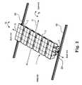
- FIG. 1shows a photovoltaic power system according to the present invention.
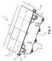
- FIG. 2shows an example of the system of FIG. 1 mounted.
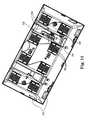
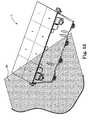
- FIG. 3shows the mounted system of FIG. 2 on a roof.
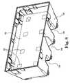
- FIG. 4shows a portion of a concentrator module, or “bucket”, from the system of FIG. 1 .
- FIG. 5shows a concentrator module, or “bucket”, from the system of FIG. 1 , including optional pointing sensors.
- FIG. 6shows a top view of a portion of a bucket assembly of a photovoltaic concentrator module used in the system of FIG. 1 .
- FIG. 7shows the inboard and outboard regions of system 1 of FIG. 1 .
- FIG. 8shows the bucket assembly of FIG. 6 including a sun shield.
- FIG. 9shows a top, close-up, sectional view of the bucket in FIG. 6 with the heat sink assemblies removed.
- FIG. 10shows a bottom, close-up, sectional view of the bucket in FIG. 6 with the heat sink assemblies removed.
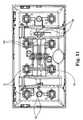
- FIG. 11shows a bottom view of the bucket shown in FIG. 6 with the back end assemblies removed.
- FIG. 12shows a top, close up view of the bucket in FIG. 6 with the back end assemblies removed.
- FIG. 13shows a close-up view of a portion of the bucket in FIG. 6 with the back end assemblies removed.
- FIG. 14shows the solar cell assembly of FIG. 18 mounted onto a heat sink and having the secondary optic of FIG. 8 mounted onto the solar cell assembly.
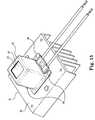
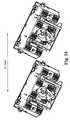
- FIG. 15shows a completed back end assembly that can be used in the system of FIG. 1 .
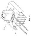
- FIG. 16is another view of the back end assembly shown in FIG. 15 , with the can portion in a transparent view to see the interior.
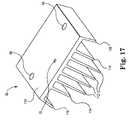
- FIG. 17shows a perspective view of the heat sink shown in FIG. 15 .
- FIG. 18shows a preferred solar cell assembly that can be used in the system of FIG. 1 .
- FIG. 19shows a close-up view of a portion of the solar cell assembly shown in FIG. 18 .
- FIG. 20shows one of the eight concentrating elements from the concentrator module shown in FIGS. 4 and 5 .
- FIGS. 21A and 21Bshow schematic diagrams of a photovoltaic concentrator assembly not having a secondary optic.
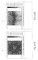
- FIGS. 22A , 22 B, 23 A, and 23 Bshown illumination patterns associated with a secondary optic used in the system of FIG. 1 .
- FIG. 24illustrates the beam stirring action of a secondary optic used in the system of FIG. 1 .
- FIG. 25shows a schematic of a preferred secondary optic used in the system of FIG. 1 .
- FIG. 26shows a perspective view of an alternative secondary optic that can be used in the system of FIG. 1 .
- FIG. 27is an exploded view of a portion of the solar cell assembly shown in FIG. 14 .
- FIG. 28shows a close up perspective view-of the sun position sensor shown in FIG. 1 .
- FIG. 29shows the sensor shown if FIG. 28 with the clear cover removed.
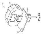
- FIG. 30shows the back side of the sensor shown in FIG. 28 .
- FIG. 31shows the sensor shown in FIG. 30 with the back cover removed.
- FIG. 32shows the internal portion of the sensor shown in FIG. 28 .
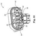
- FIG. 33shows a close-up view of a portion of the sensor shown in FIG. 31 .
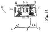
- FIG. 34shows a sectional view of a portion of the sensor shown in FIG. 28 .
- FIG. 35shows a partial, alternate view of the system shown in FIG. 1 .
- FIG. 36shows an alternate-view of the system shown in FIG. 1 .
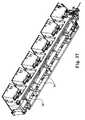
- FIG. 37shows an alternate view of the system shown in FIG. 1 .
- FIG. 38shows a close-up view of a portion of the system shown in FIG. 37 .
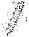
- FIG. 39shows a portion of the chassis frame shown in FIG. 37 , with the concentrator modules removed.
- FIG. 40shows the articulation mechanism shown in FIG. 37 , with the concentrator modules removed.
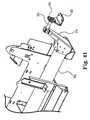
- FIG. 41shows a close-up view of the gooseneck attachment shown in FIG. 40 .
- FIG. 42shows an electronics housing associated with the articulation mechanism shown in FIG. 40 .
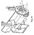
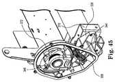
- FIG. 43shows the tilt axis drive mechanism for the articulation mechanism shown in FIG.40 .
- FIG. 44shows the tilt axis drive mechanism of FIG. 43 with the cover removed.
- FIG. 45is another view of the tilt axis drive mechanism of FIG. 43 with the cover removed.
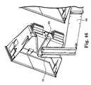
- FIG. 46shows a cross-sectional view of a portion of the system shown in FIG. 1 .
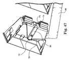
- FIG. 47shows another cross-sectional view of a portion of the system shown in FIG. 1 .
- FIG. 48shows another cross-sectional view of a portion of the system shown in FIG. 1 .
- FIG. 49shows a portion of the system shown in FIG. 1 , with two concentrator modules removed.
- FIG. 50shows a close-up view of a portion of FIG. 49 .
- FIG. 51shows the bucket of FIG. 6 with wiring.
- FIG. 52shows a wiring schematic associated with the wiring layout shown in FIG. 51 .
- FIG. 53shows the module of FIG. 5 in the context of a shadow.
- FIG. 54is a photograph of control electronics used in connection with the sensor shown in FIG. 28 .
- FIG. 55shows two concentrator modules as shown in FIG. 5 that are on adjacent solar panels, with the remaining solar panel removed.
- FIG. 56shows a preferred embodiment of the arrangement shown in FIG. 55 .
- FIG. 57shows an arrangement similar to that shown in FIG. 55 , but with alternative concentrator modules.
- FIG. 58shows another view of a concentrator module of FIG. 57 .
- FIG. 59shows the arrangement shown in FIG. 55 with an optional and additional articulation axis.
- the present inventioncan provide a concentrating solar panel that in some embodiments may be similar in size to traditional solar panels, or, in other embodiments, may be longer and narrower than traditional solar panels, resulting in lower amortized installation costs.
- solar concentrating modules and/or solar panels according to the present inventioncan produce as much or more power than an equivalently-sized traditional solar panel in many representative embodiments.
- Photovoltaic power system 1(also referred to herein as solar panel 1 ) includes a plurality of moveable photovoltaic concentrator modules 2 and articulating mechanism 3 . As shown in FIG. 1 , photovoltaic power system 1 has a first dimension, length “L” and a second dimension “W,” where length is the longer dimension and width is the shorter dimension. It is noted that concentrator modules 2 also have a width and a length, where width is the shorter dimension and length is the longer dimension.
- the concentrating solar panel 1is preferably designed for installation using standard photovoltaic rack equipment, such as is available from Direct Power and Water.
- the physical layout of such racking on a rooftopmay be uncontrolled to a degree, and further, there may be some movement in the racking over time, due, for example, to thermal expansion or contraction, or due to changes in roof weight load, such as when water pools or when rooftop equipment such as air conditioners are installed nearby.
- FIG. 2One exemplary approach to mounting the concentrating solar panel 1 is shown in FIG. 2 , wherein panel 1 mates with rail 350 and rail 352 . Rails 350 and 352 can be provided by an installer.
- modules 2can be articulated in a “tilt” motion and a “tip” motion.
- tilttilt
- tilt motionmeans articulation about the short axis 15 of module 2 (e.g., about the axis running north-south).
- tip motionmeans articulation about the long axis 17 of module 2 (e.g., about the axis running east-west when the buckets are pointed at zenith).
- each module 2 in panel 1has a separate tip axis 17 , but all modules 2 in panel 1 share the same tilt axis 15 .
- each module 2articulates in place about the tilt axis 15 and about the tip axis 17 of each module 2 . Articulating modules 2 in place can help system 1 have a low profile. Rooftop installation can then be simpler. Low profile means relatively low wind profile.
- a low profile system 1can allow conventional installation techniques to be used which is a substantial market advantage.
- a low profile system 1can also help the modules 2 to be relatively less visible from street level, thereby helping with permitting approvals, which can be another market advantage.
- the modules 2preferably point in synchrony at the sun.
- each photovoltaic concentrator module 2articulates in place, i.e., each concentrating module 2 articulates about a separate first axis that is substantially parallel to the long dimension of module 2 (e.g., tip axis 17 ) such that the first axes 17 of system 1 lie substantially in the same plane and are substantially parallel to each other.
- each concentrating module 2preferably articulates about a same second axis that is substantially parallel to the short dimension of module 2 (e.g., tilt axis 15 ) such that the first axes 17 are substantially perpendicular to the second axis 15 .
- second axis 15remains substantially fixed in orientation/position.
- FIG. 3illustrates a mounting scheme in the context of an entire roof, wherein a set of rails 354 are supported on a set of struts 356 , providing a multiplicity of potential mounting points. Rails 354 and 356 can be provided by an installer.
- the modules 2 of system 1are packed unusually close together and/or close to adjacent systems similar to or the same as system 1 , yet can articulate in tilt and tip to track the sun without colliding.
- Modules 2can be packed so close to other modules 2 within a given system 1 and/or to modules 2 in adjacent systems 1 because, e.g., the height of an individual module 2 is relatively short thereby allowing modules 2 to articulate without colliding.
- Adjacent systems 1can be packed relatively close to each other also because in preferred embodiments, system 1 does not have frame structure located at a position of perimeter of system 1 that would interfere to an undue degree with positioning two or more systems 1 next to each other.
- modules 2can be unusually tolerant to shading that may occur, thereby permitting such relatively close packing. Because modules 2 can be packed so close to each other and/or adjacent systems, system 1 can provide an aperture density (aperture area per unit area of system 1 that can receive incident sunlight) that allows a desired power output, e.g., from a limited roof area.
- each solar concentrator module 2(also referred to herein as photovoltaic concentrator module 2 ) includes a main body portion 8 (also referred to herein as “bucket”), a set of heat sink assemblies 10 , an aperture 4 through which sunlight may enter the bucket 8 , lens 6 , wiring (not shown), an optional sun sensor. 212 , an optional sunlight shield 160 (see FIG. 8 ), and one or more additional optional components described herein and/or known to be used in solar concentrator modules.
- bucket 8includes side walls 138 , 140 , 142 , and 143 , and base (floor) 145 .
- Side walls 138 , 140 , 142 , and 143 , and base 145help define an inboard region 127 of bucket 8 .
- bucket 8also includes optional cavities 134 and 136 , notches 146 , 148 , 150 , 152 , 154 , and 156 , and additional features discussed below.
- cavities 134 and 136permit the bucket 8 to attach to solar panel 1 at tip axis 17 .
- the linkage (discussed below) of articulating mechanism 3 that is associated with tip axis 17mates with bucket 8 in the pair of cavities 134 and 136 .
- Tip axis 17is preferably at or substantially near the center of gravity of bucket 8 . Having tip axis 17 at or substantially near the center of gravity of bucket 8 can advantageously help minimize the amount of torque needed to move bucket 8 in tip motion and/or to hold bucket in one or more fixed positions along the range of tip motion.
- bucket 8may be attached to articulation mechanism 3 by any number of mating points, and the mating points may be at any location.
- there may not be any cavities 134 and 136and the linkage of articulation mechanism 3 that is associated with tip axis 17 may mate with bucket 8 at the exterior surfaces 137 and. 139 of side walls 140 and 138 , respectively.
- the overall width W of panel 1can be relatively smaller.
- attaching bucket 8 to articulating mechanism 3 at one or more positions in the outboard region 129may have the effect of increasing the overall width W of solar panel 1 .
- reducing the overall width W of panel 1relatively, while maintaining the same total collecting area, can increase the overall efficiency of panel 1 , which can yield significant benefits in the overall economics of solar installations (e.g., rooftop installations).
- inboard region of a solar concentratormeans the volume of space between the side walls of a solar concentrator, the underside of a concentrator base, or the exterior surface of concentrator side walls that are approximately perpendicular to the tilt axis 15 .
- the inboard region 127 of bucket 8includes the space between side walls 138 , 140 , 142 and 143 , the exterior surface of side walls 142 and 143 , and the underside of base 145 .
- concentrator 2has an interior region defined as the space between side walls 138 , 140 , 142 and 143 , below lens 6 , and above base 145 .
- “outboard region” of a solar concentratormeans the volume of space surrounding the side walls of a given solar concentrator that are approximately parallel with tilt axis 15 .
- the outboard region 129includes the space outward from side walls 138 and 140 . Referring to FIG.
- the inboard regionincludes the interior area of the system footprint, the underside of the system footprint, and the exterior ends.
- the outboard region of system 1includes the exterior area on the sides.
- concentrator 2has an exterior region defined as the space outward from side walls 138 , 140 , 142 and 143 , outward from lens 6 , and outward from base 145 .
- a cavitydoes not impose on the path of the rays of sunlight converging on a heat sink assembly 10 .
- a cavityis positioned outside one or more converging cones of light.
- lens parquet 6has four individual lenses 12 in the east-west direction.
- Cavities 134 and 136are preferably positioned in base 145 such that cavities 134 and 136 are located outside of each converging cone of light associated with each lens 12 .
- base 145also has a space for wiring hub 132 (discussed below) that is located outside of each converging cone of light associated with each lens 12 .
- the pointing accuracy of bucket 8can be relatively improved.
- notches 146 , 148 , and 150are located in southern side wall 142 . As shown, notches 146 and 150 are aligned with cavities 136 and 134 , respectively. Notches 146 , 148 , and 150 can help provide clearance for certain elements (discussed below) of articulation mechanism 3 . Notches 146 , 148 , and 150 allow bucket 8 to have a desired range of motion about tip axis 17 while retaining the ability of the attachment linkage associated with tip axis 17 to mate with bucket 8 at or substantially near the center of gravity of bucket 8 .
- notches 152 and 154can help bucket 8 have a desired range of motion in the northern direction, while still maintaining the low center of gravity.
- the present inventionalso appreciates that the ability of the cavities 134 and 136 , and notches 146 , 148 , 150 , 152 , and 154 , to provide for the desired range of articulation, while still allowing attachment at the center of gravity, is related to the aspect ratio of the bucket.
- an alternative embodiment with a 4 by 3 lens parquet, instead of the preferred 4 by 2can suffer from a reduced range of motion in tip, since the base of the bucket begins to collide with the support structure when moving through a desired range of motion, in spite of the cavities and notches.
- the preferred aspect ratiois thus strongly affected by the preferred cavities and notches and range of motion, because cavities and notches are preferably sizeable enough to provide a desired clearance for the support structure and attachment linkage that might impinge upon the converging cones of light focused by the lenses 6 and/or upon the input aperture 4 , thus blocking light and reducing the power output of the system 1 .
- the preferred aspect ratiois influenced by the desired range of motion together with the desire to couple the attachment linkage about the tip axis 17 within the interior of bucket 8 .
- eight notches 156are provided in the bucket 8 to help support an optional (not shown) support frame for the lens parquet 6 .
- the framecan include four strips of sheet metal.
- Each strip of sheet metalcan be coupled between a pair of oppositely positioned notches 156 . As shown, three pairs of oppositely positioned notches 156 each run north-south and one pair of oppositely positioned notches 156 runs east-west.
- each strip of sheet metalcan be aligned edge-on to the incoming sunlight and along the seams of the eight individual lenses 12 of parquet 6 .
- the strips of sheet metaltend to not block incoming sunlight to an undue degree.
- the support framecan advantageously help mitigate any sag of lens 6 that may occur and/or help provide support to the lens 6 so as to help withstand impacts.
- Bucket 8includes eight optional mounting holes 164 and eight pairs of optional inserts 166 .
- FIGS. 9 and 10show a mounting hole 164 and pair of inserts 166 .
- a heat sink assembly 10(discussed below) can be positioned in mounting hole 164 and attached to bucket 8 .
- heat sink assembly 10is attached to bucket 8 using inserts 166 .
- inserts 166are threaded and fit into (e.g., molded into) gusseted cavities 168 .
- the fastenerse.g., screws or the like
- a watertight adhesive sealis preferably applied to at least a portion of the perimeter of hole 164 .
- bucket 8also includes optional “buttons”, or raised dots, 170 .
- Buttons 170can help control the thickness of the bond line of an adhesive that may be used to seal heat sink 62 (discussed below) to bucket 8 .
- buttons 170can help define a certain space between the bucket 8 and the heat sink 62 . Accordingly, buttons can help provide a uniform bond line and a desirable seal.
- buttons 170are molded into bucket 8 .
- bucket 8also includes optional slot 172 , insert 174 (preferably threaded), and raised nub 176 , which are used to attach a mounting bracket 380 (discussed below) to bucket 8 .
- a bucket according to the present inventioncan optionally include one or more vent ports. Vent ports can allow the air in the inboard region 127 of the concentrator module 2 to equalize in pressure with the air outside of the module 2 , as the barometric pressure outside the module 2 varies with time. Allowing the air pressure in concentrator 2 to equalize with the atmosphere can help enhance the reliability of concentrator 2 .
- bucket 8includes vent port 204 . As shown, one exemplary location for vent port 204 is on cavity 134 so that vent port 204 is relatively inaccessible to fingers, tools, and the like.
- Vent port 204preferably includes a semi-permeable membrane.
- vent portpreferably includes a gas-permeable filter to help prevent contaminants and liquid (e.g., water) from entering the concentrator module 2 .
- vent port 204includes a gas-permeable filter that is also permeable to water vapor, such that any condensation that may form inside the bucket 8 can escape, such as, for example, when the module is pointed at the sun in the morning and begins to warm up.
- Exemplary filter materialincludes any gas-permeable material suitable for a solar concentrator such as a film, a foam, combinations of these, and the like.
- One exemplary materialincludes an adhesive expanded polytetrafluoroethylene (ePTFE) patch commercially available under the tradename Gore-Tex® from W. L. Gore & Associates, Inc., Newark, Del.
- ePTFEadhesive expanded polytetrafluoroethylene
- Another exemplary materialis commercially available under the tradename Tyvek® from DuPont, Wilmington, Del.
- Bucket 8can optionally include one or more mounting features 210 .
- Mounting feature 210can be used to mount sun sensor 212 (discussed below). As shown in FIGS. 1 , 5 , 6 , 11 , and 13 , bucket 8 preferably includes at least four mounting features 210 .
- mounting feature 210includes ledge 214 between two beveled regions 216 and 218 , and two recesses 220 for fastening sun sensor 212 to mounting feature 210 .
- Any type of fastener suitable for mounting sun sensor 212 to mounting feature 210can be used such as screws and the like. In a preferred embodiment, self-tapping screws can be used to fasten sun sensor 212 to mounting feature 210 .
- recesses 220have a form such that mounting feature 210 will remain substantially watertight if a sun sensor 212 is not installed on mounting feature 210 .
- sun sensors 212are installed on fewer than all mounting features 210 of a given solar panel. For example, as shown in FIG. 1 four sun sensors 212 are installed on one of the six concentrator modules 2 .
- the range of motion of bucket 8 about the tip axis 17can be any desired range of motion.
- the range of articulation about the tip axis 17is asymmetric.
- the preferably asymmetric range of motionhelps ease the attachment of the tip axis support at the center of gravity of the bucket 8 .
- the range of tip motioncan be from 20 degrees from zenith in a first direction to 70 degrees from zenith in a second direction.
- the first directionis north if in the northern hemisphere and the second direction is south if in the northern hemisphere.
- cavities 134 and 136are asymmetric in shape relative to the tip axis 17 of rotation to correspond to the asymmetric range of motion.
- cavity 134is located on the east side of module 2 and cavity 136 is located on the west side of module 2 .
- the notions of “east” and “west”come about because of an asymmetric range of motion. Since the solar panel 1 can have a preferred installation orientation (e.g., on a roof), there is a notion of east and west sides of bucket 8 . Of course, these definitions are with respect to the northern hemisphere. If solar panel 1 is installed in the southern hemisphere, these directions are reversed.
- FIG. 8shows optional sunlight shield 160 .
- high-intensity spots of sunlightmay impinge on one or more features located in the inboard region 127 of bucket 8 (e.g., the base 145 of bucket 8 , wiring, combinations of these, and the like).
- a sunlight shield 160is provided to help deflect the sunlight.
- the sun shieldincludes apertures 162 which allow the converging sunlight beams to reach the inputs of the secondary optics 24 .
- Standoffs in the bucket 8help prevent the sunlight shield 160 from contacting the internal wiring or the wiring hub 132 .
- Sunlight shield 160can be made of any material that helps suitably deflect incoming sunlight.
- a preferred material for constructing sunlight shield 160includes aluminum sheet metal.
- Bucket 8can be made from one or more materials suitable for an articulating photovoltaic concentrator. Desirable material properties for bucket 8 include fire resistance, long-term dimensional stability, precision manufacturability, resistance to ultraviolet radiation, watertightness, structural strength, low thermal expansion, low cost, low to substantially no outgassing (low VOC), combinations of these, and the like. Exemplary materials of construction for bucket 8 include one or more materials such as plastic, metal (e.g., aluminum sheet metal), epoxy, and combinations thereof. Preferred plastic materials include thermosetting materials. Preferred thermosetting materials include epoxy, sheet molding compound (SMC), bulk molding compound (BMC), and combinations thereof. Sheet molding compound is a fiber-glass (typically relatively long glass fibers) reinforced thermosetting compound in the form of a sheet.
- Desirable material properties for bucket 8include fire resistance, long-term dimensional stability, precision manufacturability, resistance to ultraviolet radiation, watertightness, structural strength, low thermal expansion, low cost, low to substantially no outgassing (low VOC), combinations of
- Sheet molding compoundcan also include one or more of fillers, maturation agent, catalyst, and mold release agent.
- Bulk molding compoundis a “puttylike” compound that is a blend of thermoset plastic resin and fiber-glass (typically relatively short glass fibers).
- Bulk molding compoundcan also include one or more of filler, catalyst, stabilizer, pigment.
- bucket 8is manufactured from material including at least sheet molding compound.
- mounting feature 210is a relatively complex feature that is preferably positioned on a side wall of bucket 8 as close to aperture 4 as possible. Also, mounting feature 210 is preferably positioned such that mounting feature does not interfere with incoming light in inboard region 127 to an undue degree. As shown, ledge 214 of mounting feature 210 can be positioned in a side wall of bucket 8 such that part of ledge 214 protrudes into inboard region 127 and part of ledge 214 protrudes into the exterior space of bucket 8 .
- mounting feature 210can be positioned relatively close to aperture 4 of bucket 8 by positioning ledge 214 in such a manner.
- the two beveled regions 216 and 218can advantageously provide draft angle characteristics that permit ledge 214 to be positioned in such a manner using molding techniques. Having appropriate draft angle characteristics can permit a feature to be desirably removed from a mold.
- Forming bucket 8 with relatively fewer piecescan be highly advantageous because, as discussed above, bucket 8 can include one or more complex features.
- Forming bucket 8 from sheet metalwould typically involve assembling relatively more individual complex parts and fasteners. But by molding a thermosetting material into bucket 8 , the complexity of the bucket 8 can typically be absorbed into the cost of tooling, which can be done once, and the cost to replicate buckets 8 in high volume can then be typically less than for a sheet metal bucket 8 .
- bucket 8is a seamless, unitary piece made from sheet molding compound.
- Forming bucket 8 from a plasticis advantageous because of the relatively light weight of bucket 8 , helping to reduce the weight of the overall system 1 and ease the installation and handling of system 1 .
- system 1can weigh less than about 100 pounds.
- One method of making bucket 8 from sheet molding compoundcan include placing one or more sheets or portions of sheets of sheet molding compound over a female plug.
- the female plugcan include the features of the inside of bucket 8 .
- a male plugcan be mated with the female plug so that the sheet molding compound is compressed between the female plug and male plug.
- the sheet molding compoundis compressed between the female and male plug at an elevated temperature to cause the thermosetting plastic to at least begin to cure.
- Forming bucket 8 in this mannercan allow complex features to be precisely positioned in bucket 8 and consistently positioned from bucket 8 to bucket 8 .
- co-molded partssuch as, for example, threaded inserts and the like, can be precisely placed in bucket 8 and consistently placed from bucket 8 to bucket 8 .
- the selection of sheet molding compound for the preferred embodiment of the bucketcan help meet cost targets while at the same time allowing one or more of the features discussed above to be included in bucket 8 .
- heat sink assembly 10includes heat sink 62 , solar cell assembly 50 , secondary optic 24 , and housing 92 .
- Heat sink 62preferably includes holes 66 and 70 , as well as holes (not shown) to accommodate rivets 68 .
- heat sink 62optionally includes holes 64 .
- Hole 70can be included to accommodate attachment of optional wiring clamp 72 , as shown in FIG. 16 .
- Holes 66are preferably used to mount heat sink assembly 10 to bucket 8 using any suitable fastener (e.g., screws or the like). Holes 66 are preferably oversized to allow minor adjustment of the position of heat sink assembly 10 with respect to the bucket 8 prior to final fastening. Holes 64 may be used, for example, to attach grounding wires to the heat sink 62 . Referring to FIG. 17 , the heat sink 62 is shown with solar cell assembly 50 removed before holes 64 and holes (not shown) for rivets 68 are included.
- heat sink 62includes a base plate 110 , and fins 112 , 114 , and 116 .
- Fins 112 , 114 , and 116preferably have different lengths.
- Fins 112 , closest to the heat source (as shown, solar cell assembly 50 ) that is thermally coupled to heat sink 62are preferably the longest.
- Fins 116furthest from the heat source (as shown, solar cell assembly 50 ) that is thermally coupled to heat sink 62 , are preferably the shortest.
- Varying fin heightcan have the effect of keeping the path from the heat source (e.g., solar cell assembly 50 ) to the tip of each fin 112 , 114 , and 116 , similar, which is desirable since longer source-to-tip distances typically require thicker metal in order to achieve equivalent thermal conduction from source to fin tip.
- fins 116are preferably angled outward so as to increase the overall projected area of the heat sink 62 as seen from the bottom of heat sink 62 . Increasing the projected area can improve the radiative performance of the heat sink 62 .
- heat sink 62is a preferred embodiment, any number of fins of any length, angled at any angle, may be used in connection with concentrator 2 .
- Alternative heat sinksinclude, for example, pin heat sinks, corrugated sheet metal heat sinks, and the like.
- Heat sink 62can be made from any material suitable for transferring heat in a desirable manner from solar cell assembly 50 .
- heat sink 62is made from material including aluminum.
- the aluminumcan by anodized such as clear-anodized or black anodized.
- the aluminumis clear-anodized which has been observed as helping to improve radiative performance without unduly impacting convective performance.
- solar cell assembly 50includes a solar cell 52 , a bypassing element 54 , circuit board 51 ; and electrical wires 53 and 56 .
- the solar cell 52can be any type and size that is suitable for use in a solar concentrator.
- a preferred solar cellincludes a high-efficiency triple-junction solar cell, such as that manufactured by Emcore or Spectrolab. As shown, solar cell 52 is preferably a square (e.g., seven and one-half (7.5) millimeters by seven and one-half (7.5) millimeters).
- Bypassing element 54is optional and may be a diode or another type of element, such as an active element such as a metal-oxide-semiconductor field-effect transistor (MOSFET).
- MOSFETmetal-oxide-semiconductor field-effect transistor
- a MOSFETis a device that can be used to amplify or switch an electronic signal.
- Bypassing element 54is preferably a diode.
- a bypassing elementcan help provide an alternate path for current flow in cases where power is not being produced, for example, when a shadow blocks light from reaching the solar cell 52 . Providing an alternate current path besides through the solar cell 52 itself helps to allow bucket 8 and system 1 to continue to produce a desired power output even if one or more of the solar cells 52 is not producing any power.
- Circuit board 51can be any electrical wiring that can function as a circuit board and that is suitable for use in solar cell assembly 50 .
- solar cell 52 and bypassing element 54are attached to circuit board 51 .
- Solar cell 52 and bypassing element 54can be attached to circuit board 51 by any manner suitable for use in solar cell assembly 50 .
- the solar cell 52is attached to circuit board 51 in a substantially void-free manner.
- a conductive epoxycould be used to bond solar cell 52 to circuit board 51 in a substantially void-free manner.
- the circuit board 51can be made of any material suitable for use as a circuit board in solar cell assembly 50 .
- a preferred circuit board 51includes a substrate having at least a first layer that is electrically insulating and a second layer that is electrically conductive, where the second layer is electrically coupled to solar cell 52 and optional bypassing element 54 .
- the first layeris thermally conductive.
- An even more preferred circuit board 51includes a substrate having at least first and second faces that are electrically conductive, and an electrically insulating core sandwiched between the first and second faces.
- the electrically insulating coreis thermally conductive.
- a preferred electrically insulating materialincludes ceramic material.
- Preferred electrically conducting materialincludes metal.
- the first and second electrically conducting facescan be two different metals. If two different metals are used for first and second electrically conducting faces, preferably the linear thermal expansion is matched among the first and second faces.
- a circuit board having at least first and second faces that are electrically conductive, and an electrically insulating core sandwiched between the first and second facescan prevent warping (“potato-chipping”) of the substrate that might otherwise occur due to changes in temperature.
- a preferred circuit board 51includes a “direct-bonded copper” (“DBC”) double-sided copper substrate. DBC double-sided copper substrates are well known and include a ceramic tile having a sheet of copper bonded to each side. Exemplary ceramic tiles can be made out of alumina, aluminum nitride, beryllium oxide, combinations of these, and the like.
- Wires 53 and 56help provide an electrical circuit so that photovoltaically generated electricity can be delivered from solar cell 52 as electricity is generated.
- Wires 53 and 56can be attached to solar cell assembly 50 in any suitable manner.
- Resistance-welding wires 53 and 56is a method of attachment because resistance-welding can occur over such a relatively quick time period that the heat generated for welding typically is not unduly transferred away by surrounding heat sinks such as, e.g., heat sink 62 . Also, because resistance-welding can occur over such a relatively short time period, heat generated from the welding process typically does not transfer to surrounding solder-joints in a manner that causes the solder-joints to unduly soften and/or become undone.
- the solar cell assembly 50preferably includes fiducial marks, such as holes 57 , for aid in automated assembly, such as in assembly using a machine vision system to precisely locate the solar cell assembly 50 into the bucket 8 .
- an additional optional optical element 24can be positioned at the focal point 20 of an individual lens 12 .
- solar cell 52may be placed at the focus 20 of one or more lenses 12 .
- secondary optic 24can help increase the acceptance angle of the concentrator module 2 .
- the increased acceptance angle that can be provided by the optical secondary 24can be described by reference to FIGS. 21A and 21B , which illustrate the case with no optical secondary present.
- FIG. 21Ais a diagram of a concentrating optical assembly, including a lens portion 514 focusing the sun's rays 516 onto a solar cell 522 .
- FIG. 21Billustrates the situation if the incoming sunlight rays 516 are at an angle 518 relative to lens portion 514 . If angle 518 exceeds a certain value, the focused rays 512 tend to fall off the edge of the solar cell 522 , thereby reducing or eliminating the production of electricity.
- the optical secondary 24can effectively magnify (albeit in a non-imaging fashion) the area in which solar cell 522 can capture incident light 16 .
- Optical secondary 24presents a larger area at the mouth 26 onto which the focus 20 may fall. Presenting a larger area at mouth 26 tends to have the effect of increasing the acceptance angle of the optical system as a whole.
- the optical secondary 24can optionally perform a function of illumination homogenization (also known as “beam stirring”). Illumination homogenization redistributes the hyper-concentrated light at the entrance aperture (or mouth) 26 of secondary optic 24 into a much more uniform illumination pattern at the exit aperture (or throat) 28 of secondary optic 24 . Secondary optics that perform the beam stirring function will tend to be taller than secondary optics that do not perform the beam stirring function as well.
- FIGS. 22A , 22 B, 23 A, and 23 Bhelp illustrate the effect of beam stirring.
- FIGS. 22A and 22Bshow the illumination pattern at the focus 20 of the lens 12 , for the cases of FIGS. 21A and 21B , respectively.
- a preferred beam stirring secondary optic 24can nominally convert the illumination patterns 32 and 33 into the illumination patterns 34 and 36 , respectively.
- Illumination pattern 32is present at the mouth 26 when an individual lens 12 is pointed substantially directly at the sun.
- Illumination pattern 32is converted by secondary optic 24 into pattern 34 , which is present at the throat 28 of secondary optic 24 .
- Illumination pattern 33is present at the mouth 26 when an individual lens 12 is pointed at the sun at an angle of one degree.
- Illumination pattern 33is converted by secondary optic 24 into pattern 36 , which is present at the throat 28 of secondary optic 24 .
- the preferred secondary optic 24can produce a fairly uniform illumination pattern 36 even if an individual lens 12 is not pointed directly at the sun.
- FIG. 24is a three-dimensional view of the input and output illumination patterns shown in FIGS. 22A and 23A .
- the ray bundle entering the mouth 26 of the secondary optic 24is tightly focused, but secondary optic 24 causes numerous reflections which tend to “stir” the rays to produce a relatively uniform illumination at the throat 28 .
- optical secondary 24preferably includes multiple distinct geometric zones 40 , 45 , and 47 .
- Zone 47tends to help capture and redirect the incoming light if the lens 12 is not pointed directly at the sun.
- Zone 40tends to concentrate the incoming light towards the throat 28 , and zone 45 is a physical transition region between zones 45 and 47 .
- optical secondary 24optionally includes flange 42 , which preferably does not contribute in the optical function of the secondary optic 24 but can aid in mechanically securing the secondary optic 24 in position on heat sink assembly 10 (discussed below).
- flange 42could be replaced with one or more tabs (not shown) that can similarly aid in mechanically securing the secondary optic 24 in position on heat sink assembly 10 .
- secondary optic 24could have no flange 42 or tabs (not shown).
- any secondary optic for use in solar concentratorscould be used in concentrator 2 .
- an alternative secondary optic 80is shown in FIG. 26 .
- Secondary optic 80includes a front surface 82 that may be curved, sloped, or otherwise shaped in order to improve the acceptance angle for off-axis rays.
- the front surface 82 of secondary optic 80can function similar to the function of a field lens in the art of imaging optical systems, thereby tending to collimate off-axis rays and improving the field of view (i.e., the acceptance angle) of the secondary optic 80 .
- secondary optic 80can be optimized to accept a ray cone that nominally comes into the secondary optic 80 from a slightly off-normal direction, and thus the input aperture 82 is generally sloped in addition to having the curvature associated with a field lens.
- Another alternative secondary opticincludes a mirrored, open-air secondary optic that is used by Amonix, Inc., Torrance, Calif.
- a secondary optic for use in concentrator 2can have any number of sides (or even have a round or elliptical profile) and any shape that is suitable for use in a solar concentrator.
- a secondary optic for use in concentrator 2has four sides.
- Secondary optic 24can be made out of any material suitable for used in solar concentrator 2 .
- secondary optic 24can be made out solid glass, utilizing total internal reflection (TIR) to reflect rays towards the exit aperture 28 of secondary optic 24 .
- TIRtotal internal reflection
- Secondary optic 24can optionally include one or more coatings known for use on secondary optics.
- secondary optic 24could use a reflective coating on the sidewalls of secondary optic 24 .
- secondary optic 24could include an approximately transparent anti-reflective coating on the entrance aperture 26 of the secondary optic 24 to help improve coupling of focused sunlight into the secondary optic 24 .
- housing (“can”) 92is positioned over and contacts secondary optic 24 in a structurally rigid manner.
- can 92includes aperture 93 , which is at least the size of entrance aperture 26 of the secondary optic 24 so that can 92 does not unduly block light incident upon aperture 26 .
- housing 92can at least partially protect secondary optic 24 from the environment of inboard region 127 .
- an inner surface of can 92contacts flange 42 in a structurally rigid manner.
- secondary optic 24(preferably flange 42 ) forms a seal with the top inner surface of can 92 in a structurally rigid manner.
- secondary optic 24(preferably flange 42 ) can be bonded to the top inner surface of can 92 (e.g., with a sealant) in a structurally rigid manner.
- can 92can be affixed directly or indirectly to heat sink 62 in any manner suitable for use with heat sink assembly 10 .
- can 92is affixed to heat sink 62 with rivets 68 .
- can 92could be substituted with one or more mechanical members that can contact secondary optic 24 in a structurally rigid manner and, optionally, at least partially protect secondary optic 24 from the environment of inboard region 127 .
- Heat sink assembly 10can be assembled in any convenient manner.
- FIG. 27is an exploded view of a preferred material stack of the solar cell assembly 50 and secondary optic 24 .
- the order of the explosionis suggestive of a preferred order of assembly.
- solar cell assembly 50is first produced from circuit board 51 , solar cell 52 , and a bypass diode 54 .
- an encapsulant 102can be applied over a portion of the circuit board 51 to protect and insulate the solar cell leads 103 .
- a thin layer of optical adhesive or gel 106is preferably applied to the top surface of solar cell 52 and secondary optic 24 is attached to solar cell 52 in a manner such that concentrated light exiting the concentrating optic is incident upon the photovoltaic cell.
- the circuit board 51 -with-secondary-optic 24is then preferably bonded with thermal adhesive 104 to heat sink 62 .
- a conformal coating 108is preferably applied to cover the entire solar cell assembly 50 .
- Coating 108can contact optical adhesive 106 but preferably leaves a small gap so that coating 108 does not contact secondary optic 24 .
- the gapis preferably a few thousandths of an inch, but is exaggerated in FIG. 27 for clarity.
- Optical adhesive or gel 106preferably has an index of refraction that is as high or higher than the index of refraction of the material of the secondary optic 24 , and as low or lower than the index of refraction of the material of which the solar cell 52 is constructed.
- index of refractionthat is as high or higher than the index of refraction of the material of the secondary optic 24 , and as low or lower than the index of refraction of the material of which the solar cell 52 is constructed.
- solar cell assembly 50 and heat sink 62can be assembled together in a manner such that solar cell 52 receives incident light passing through the aperture of the concentrator module 2 , preferably with a thermal adhesive.
- the present inventionteaches a number of novel approaches for producing a reliable heat sink assembly, in high volume. Techniques such as fiducial marks and oversized holes to allow for accurate robotic alignment have already been described. Another area in which novel techniques are desirable is in the assembly of the optical secondary 24 to the solar cell 52 , and of the resulting assembly 50 to the heat sink 62 . Adhesives with the desired properties mentioned earlier (for the optical adhesive, qualities like transparency and tolerance to intense ultraviolet radiation, and for the thermal adhesive, qualities like dielectric standoff and high thermal conductivity) are available, but the best adhesives may not be readily available in fast-curing formulations. Many desirable adhesives are thermally cured at elevated temperature for extended periods of time, for example an hour or more.
- fixturesDue to the desire to assemble these components with a desired level of precision, it is desirable to provide fixtures to hold the components in the proper alignment while the adhesive cures.
- such fixturesmay be expensive, so if it is desired to produce, for example, hundreds or thousands of heat sink assemblies 10 per hour, hundreds or thousands of expensive precision fixtures may be required.
- Tack curingis a technique whereby an adhesive is at least partially cured to achieve a low-strength but useful bond, allowing further operations that may rely on the bond prior to final curing, as long as the further operations do not place undue stress on the adhesive.
- a preferred method of heat sink assembly manufacturethen proceeds as follows: 1) Place one or-more solar cell assemblies into appropriately shaped receptacles in a rotary table; 2) Dispense optical adhesive onto the solar cells 52 ; 3) Using optional machine vision for guidance, optionally use a robot to precisely place secondary optics 24 onto solar cells 52 , using the fiducial marks as positional references for the machine vision system. The robot attaches a clamp or other fixture to the precision-placed assemblies to hold them in place; 4) Bring a (preferably pre-heated) heating plate up from below the rotary table to contact the prospective solar cell assemblies with secondary optics; 5) Apply beat in excess of, say, 150 C.
- each solar-cell-with-secondary assemblydispense thermal epoxy onto a heat sink; 7) Use a robot to place each solar-cell-with-secondary assembly onto a heat sink, causing the robot to press the assembly onto the heat sink with a desired force, preferably fixturing the assembly to the heat sink, freeing the robot for further operations; 8) Apply heat in excess of, say, 150 C. for a short interval, say, 50 seconds.
- some sort of ovenis instead preferably used to heat the entire prospective heat sink assembly at once. This heat will thus tack-cure both the thermal adhesive and the optical adhesive to the point where they can tolerate normal handling during assembly; 9) Remove the fixtures (and return them to a position that will allow re-use) and place the heat sink assembly onto a slow conveyer that will take it into curing oven at a temperature in excess of, say, 150 C., for a duration of, say, 90 minutes, to achieve a full-strength cure of all adhesives; and 10) Allow the completed heat sink assembly to cool, and remove it from the conveyer.
- aperture 4is preferably rectangular shaped.
- An exemplary dimension of aperture 4is approximately 29 inches by 15 inches.
- aperture 4can be any size and shape suitable for a solar concentrator.
- lens 6is preferably a “parquet” of individual lenses 12 as optical elements to concentrate sunlight.
- each individual lens 12concentrates incoming rays 16 of sunlight from aperture 14 of aperture 4 to a high intensity focus 20 .
- focus 20 of lightcan be used to create electricity from solar cell 52 .
- lens 6preferably includes a single unitary sheet of lenses 12 .
- lens 6could be made up separate, sub-sheets of lenses 12 .
- Lens 6can be made out of any optical material suitable for a lens in a solar concentrator.
- Exemplary materialsinclude plastic materials such as acrylic.
- lens 6preferably includes a 4 by 2 parquet of approximately square lenses 12 .
- lenses 12are preferably square because a square lens 12 can help make concentrator 2 shorter since the minimum practical height of a concentrator is typically driven by the largest dimension of the lens.
- Alternative embodimentsmay use other lens shapes (non-square) and different numbers of lenses in the parquet.
- the present inventionalso teaches that other types of parquets, such as parquets of hexagonal lenses may approximate a preferred aperture profile, which includes circle segments 440 (discussed below with respect to FIG. 57 ).
- Alternative embodimentstherefore include parquets of hexagonal or other-shaped lenses, or parquets of heterogeneous lenses, to help approximate a preferred “capped-rectangle” shape.
- the inventionappreciates that the amount of energy the solar panel 1 will produce tends to be directly related to the efficiency of the lenses.
- the efficiency of lenses 12can be described as the ratio of the amount of light that lens 12 properly focuses to focal point to the amount of light 16 entering the aperture 14 .
- Fresnel lensesare preferred since Fresnel lenses tend to weigh and cost relatively much less than at least some other lenses.
- the preferred lens 12is square, there are at least two ways to think about the focal length to diameter ratio of the lens 12 . With respect to width (w) of lens 12 , f/w ratios of less than 1.25 can lead to unacceptable losses of light. With respect to the diagonal (d) (which is 1.41 times the width for a square lens 12 ), f/d ratios of less than about 0.9 can lead to unacceptable losses of light.
- the present inventionappreciates that it may be challenging to produce a suitably efficient concentrator 2 whose height is much less than 2 times its width.
- a 4 by 2 array constructed of efficient Fresnel lensescan yield a concentrator 2 whose width is approximately one times the height of concentrator 2 , permitting concentrators 2 to be packed relatively tightly in solar panel 1 for a relatively high efficiency.
- parquetsthat have at least two lenses in the shortest dimension of the parquet (e.g., the north-south direction in FIG. 2 ) are preferred, so as to give a width-to-height ratio of at least 1:1.
- a parquet lens 6can be any array of lenses 12 .
- parquet lens 6could be a 4 by 1 array of lenses 12 .
- the input aperture of the concentrating module 502can be expanded by adding circle segments 440 thereby increasing the collecting area (and thus the efficiency) of the solar panel without any increase in spacing required.
- a preferred shape for the apertureis a “capped rectangle”, as illustrated by region 446 in FIG. 58 .
- This capped rectangleis constructed by first constructing circle 444 , which is the perimeter swept out by the corners of a rectangular module the module articulates in tilt motion. Lines 442 are then constructed by extending the long sides of the preferred module past the edge of the circle. The resulting interior area 446 is the preferred shape. Note that the preferred modules 2 instead use a rectangular aperture to help ease manufacturing.
- a lenshas an “m” by “n” array of individual lenses, m>1, n>1, and m ⁇ n.
- nequals 1.5 or greater, or even 2 or greater.
- the “n” dimensionoccurs along an axis that is substantially parallel to tipping axis 17 .
- Wider modulesalso modify the overall aspect ratio of the solar panel as a whole.
- the preferred embodimentselects a 4 by 2 lens parquet as a near-optimal balance between packing density, structural stiffness, and the desire to articulate about the center of gravity.
- each lens 12is preferably a Fresnel lens.
- lens 12can be a standard lens, a reflective lens, a total internal reflection-refraction (TIR-R) lens, combinations of these, and the like.
- TIR-Rtotal internal reflection-refraction
- the lensneed not be planar.
- the lensmay be dome-shaped or otherwise three-dimensional.
- Each lens 12can be any size suitable for concentrator.
- An exemplary size of lens 12is 7 inches by 7 inches.
- Lens 6can optionally include a border around the lenses 12 , e.g., a 1 ⁇ 2-inch border.
- Sun position sensor 212is illustrated in FIGS. 28-34 .
- the preferred sensor 212includes distinct narrow-angle and wide-angle sensors, each including a plurality of photodiodes which sense incident sunlight.
- the basic approachcan be consistent with the approach in Ser. No. 11/974,407 (Johnson Jr., et al.) having filing date of Oct. 12, 2007, the entirety of which is incorporated herein by reference.
- the sensor 212preferably includes a set of wide-angle sensing diodes 222 and a pair of narrow-angle sensing diodes 224 located behind precision slits 226 and masks 228 . Slits 226 and masks 228 are preferably molded into sensor body 230 .
- the preferred sun position sensors 212are single-axis sensors, designed to be principally sensitive to sun position in a preferred axis and agnostic to sun position in the other axis.
- sensor 212includes a preferably injection molded main body 230 , a clear cover 232 , and an output cable 234 .
- the volume within the clear covermay be filled with a clear material such as silicone, so as to eliminate the possibility of condensation or contamination-inside the sensor.
- FIG. 29shows the sensor 212 with the clear cover removed, and more clearly reveals wide-angle sensing photodiodes 222 and precision slits 226 .
- FIG. 30shows the back side of the sensor 212 , including back cover 228 and mounting features 231 , which mate with mounting holes 220 in features 210 on the bucket 8 .
- FIG. 31shows the sensor 212 with the back cover 228 removed, and reveals circuit board 232 and diode holder 234 .
- FIG. 32is a front view of sun position sensor 212 , and shows circuit board 232 largely covered by diode holder 234 .
- the diode holder 234is a preferably injection-molded part that provides for the diodes to be soldered to the circuit board at a preferred height above the board, and in preferred accurate orientations, as shown in further detail in FIG. 33 .
- FIG. 34shows a section view of the narrow-angle photodiodes 224 and the slits 226 which are molded into the main body 230 .
- the viewis from the top of the sensor 212 , at a plane below the slits 226 .
- slits 226can cast shadows on the narrow-angle diodes 224 .
- Mask 228provides a precision aperture onto which the shadows of slits 226 are cast, thus creating a very precise sensor even if the photodiode itself is mechanically imperfect.
- the sensors 212are preferably designed to be sensitive to sun position in only one axis, so at least two preferred sensors 212 are desired to fully determine the position of the sun. Furthermore, inasmuch as it is possible for adjacent concentrator modules 2 or nearby concentrating solar panels 1 to cast shadows, it is desirable that there be redundant sensors 212 for each of the two axes (the tilt and tip axes), so that even when one sensor 212 is shaded, the other sensor 212 can preferably still see the sun. In the preferred embodiment, redundant sensors 212 are placed on opposite sides (in the east-west sense) of bucket 8 to help provide tolerance to shadows.
- These sensors 212include both narrow- and wide-angle sensing elements. Substantially similar tracking sensors are detailed in co-pending application having Ser. No. 11/974,407 (Johnson Jr., et al.) and filing date of Oct. 12, 2007.
- the signal cables 234are fed to control electronics 239 shown in FIG. 54 (discussed below), where software can interpret the data from the sensors 212 to infer the position of the sun and command the motors to move appropriately so that the solar panel 1 points at the sun.
- the concentrating solar panel 1includes a plurality of solar concentrator modules 2 , coupled to articulating mechanism 3 .
- the preferred articulating mechanism 3 shown in FIG. 40includes frame 304 , linkage 308 , drive assembly 310 , and pivot assembly 312 .
- FIGS. 35-38show the frame 304 of articulating mechanism 3 in the context of the entire solar panel 1
- FIG. 39shows the frame 304 in isolation.
- the articulating mechanism 3(articulating in tip and tilt) is positioned underneath/beneath/below or proximal to and/or within the system 1 footprint shown in FIG. 7 .
- the concentrator modules 2are preferably physically coupled to the frame 304 at pivot points 306 in an articulating manner, which connect to the buckets 8 inside cavities 134 and 136 .
- Frame 304includes two chassis members 305 and 307 that are rigidly, physically coupled to axle (third chassis member) 302 .
- Each chassis member 305 , 307 , and 302is substantially parallel to the other chassis members and each chassis member 305 , 307 , and 302 extends along the length “L” (see FIG. 1 ) of the panel 1 footprint.
- frame 304is preferably mounted on axle 302 , which preferably pivots the frame 304 (including modules 2 ) about the tilt axis 15 (e.g., north-south axis as shown in FIG. 2 ) to move frame 304 in an arc or curve, similar to the motion of a pendulum.
- frame 304 and/or axle 302provide sufficient structural support for modules 2 within panel 1 in addition to articulating modules 2 .
- the frame 304 and/or axle 302can support the weight of the modules 2 and any additional mechanical loads (including but not limited to snow, for example) without failing, but axle 302 may undergo flexing without impacting performance.
- frame 304is separate from axle 302 .
- frame 304attaches to axle 302 at a pair of points 314 .
- These points 314are preferably positioned at locations partway along the length of the frame 304 , for example, approximately 25% and 75% of the way along the frame 304 .
- Attaching frame 304 to axle 302 at preferred points 314can reduce deflection of frame 304 and/or allow reduction of the mass of the frame 304 while retaining structural rigidity.
- the tilt axle 302preferably mates to the tilt axis 15 pivot elements 310 and 312 .
- connection points 314preferably also function as a flexure or bearing in order to help prevent transmission of bending moments between the axle 302 and the frame 304 .
- One preferred material for axle 302includes aluminum (e.g., extruded aluminum tube).
- frame 304can mate directly with the tilt axis pivots 310 and 312 .
- frame 304can flex due to the weight of the concentrator modules 2 , and typically the degree of flexing can vary as the tilt axis 15 rotates. Such variation in flexing can lead to the modules 2 pointing in slightly different directions from each other about the tip axis 17 as modules 2 articulate about the tilt axis 15 . If the modules 2 are not pointed in substantially the same direction, the acceptance angle of the concentrating solar panel 1 as a whole tends to be reduced. Thus it can be desirable to minimize such differential pointing error.
- the present inventionappreciates that, in many markets of interest, the position of the sun at midday may be relatively low in the southern sky at some times of year, such as in the winter at northern latitudes, while the midday position of the sun in summer is near zenith. It is thus desirable that the tilt axis support 312 at the preferably southern end of the concentrating solar panel 1 be implemented so as not to cast a shadow on any of the concentrator modules 2 , particularly, for example, at midday in the winter at northern latitudes. It is also desirable that support 312 allow clearance for concentrator modules 2 to articulate in tip without interference from support 312 .
- the southern end of the tilt axis 15is at a lower height than the northern end.
- This arrangementcan lead to a tilt axis 15 that is slightly inclined with respect to the plane on which the panel 1 is mounted.
- the inclined tilt axis 15typically does not unduly affect the operation of the solar panel 1 , but there advantageously may be a reduced shadowing benefit due to such inclination.
- the non-shadowing and clearance functionscan be enhanced via the gooseneck attachment piece 316 , shown in detail in FIG. 41 .
- Gooseneck 316preferably fits into axle 302 and arcs up to the desired pivot point about tilt axis 15 , which is at or substantially near the center of gravity of the moving mass of the entire solar panel 1 .
- Gooseneck 316can be made out of any material suitable for articulating, and preferably supporting, axle 302 and any load that axle 302 may bear, such as cast aluminum.
- Roller 316preferably mates to mounting plate 320 at pivot 322 via bearing 324 .
- Bearing 324can be any bearing that preferably allows for some desirable amount of range of articulation of axle 302 with respect to mounting plate 320 .
- a preferred bearing 324includes a bearing that is partially spherical bearing.
- pivot 322is preferably free to slide longitudinally in bearing 324 , thus allowing for translation of the mounting plate 320 in the, preferably, north-south direction, helping to accommodate variations in the position of mounting rails such as rails 350 and 352 in FIG. 2 .
- Bearing 324can be made of any suitable material such as, e.g., polymer.
- While the preferred embodimentcontains a single main support axle 302 , alternative embodiments may use more than one main support axle 302 .
- Axle 302is preferably articulated about tilt axis 15 by drive assembly 310 shown in FIG. 40 .
- drive assembly 310is attached to bracket 326 .
- FIG. 42also shows electronics housing 240 .
- the drive 310 end of articulating mechanism 3can be attached to a support using any suitable fastener. As shown, drive 310 is attached to mounting bracket 326 . Bracket 326 includes mounting holes 328 for attaching to mounting rails. One approach to mounting the concentrating solar panel 1 is shown in FIG. 2 , wherein bracket 326 mates to rail 350 and gooseneck mounting plate 320 mates to rail 352 . FIG. 3 illustrates this scheme in the context of an entire roof, wherein a set of rails 354 are supported on a set of struts 356 , providing a multiplicity of potential mounting points.
- mounting bracket 326mates to drive assembly 310 at pivot 332 via bearing 334 .
- pivot 332 and bearing 334preferably form a gimbal, allowing two degrees of freedom of movement at this interface, thus accommodating variations in mounting precision and mild misalignments of the tilt axis 15 , e.g., with respect to the plane of the roof.
- Universal mounting jointssuch as the gimbal formed by pivot 332 and bearing 334 as shown in FIG. 42 , may be provided at one or both ends of panel 1 .
- Panel 1can be driven, and preferably supported, about tilt axis 15 with longitudinal compliance.
- panel 1can continue to operate properly even when the racking is statically mislocated and/or dynamically moves.
- drive mechanism 310is shown in more detail.
- axle 348(and sector gear 360 , shown in FIG. 44 ) remains fixed, while the entire tilt mechanism 310 can rotate about it.
- the mechanism housingincludes cover 336 and body 338 .
- Body 338fits into tilt axle 302 .
- cover 336includes a bulge 340 to accommodate gear 344 and a pocket 342 to accommodate limit pin 346 .
- Cover 336 and body 338can be made out of any suitable material.
- One preferred materialincludes cast aluminum.
- FIGS. 44 and 45are views of the tilt drive mechanism 310 with cover 336 removed.
- Motor (not shown) in box 370provides the actuation for the mechanism 310 and is preferably a stepper motor.
- the motordrives worm gear 368 , which turns gear 344 , providing a first gear reduction.
- Gear 344thus causes worm gear 364 to spin, supported on bearings 366 , which are preferably semi-spherical polymer bearings.
- Worm gear 364then causes housing 338 to rotate about fixed sector gear 360 , providing a second gear reduction.
- Tilt mechanism 310desirably does not require maintenance, and thus preferably does not have to be lubricated.
- the preferred mechanismincludes gears made of appropriate material, for example, plastic for gears 344 and 360 , and brass for worm gear 368 .
- Worm gear 364may be an appropriate metal (e.g., stainless steel), since it interfaces with only plastic and polymeric components.
- polymeric bearings 366aid in mechanism 310 not necessarily having to be lubricated.
- Worm gear 368preferably includes brass, so that it may be assembled to the shaft of the motor via a press fit.
- Sector gear 360includes pockets 362 , into which pin 346 enters at the limits of its motion.
- Collar 372 on pin 346preferably implements a limit switch, for example, by providing a reed switch and magnet in collar 372 and one of the pockets 362 .
- FIG. 40the entire frame 304 is preferably articulated about tilt axis 15 by the action of motor.
- FIG. 40also illustrates preferred components which provide actuation about tip axis 17 (see FIG. 2 for tip axis 17 ).
- the buckets 8are preferably ganged together, so that they move in synchrony about their respective tip axes 17 .
- Each bucket 8is preferably supported at pivot points 306 and articulates about these points 306 on brackets 382 and brackets 380 .
- the buckets 8are made to articulate by the motion of linkage arm 308 .
- FIG. 35illustrates the preferred brackets 380 and 382 , frame, and linkage arm 308 .
- the frameincludes east-side rail 384 and west-side rail 386 .
- Rail 384-includes stiffener 390
- rail 386includes box stiffener 392 .
- Linkage arm 308includes stiffener 394 .
- FIGS. 46 , 47 , and 48are views of the west-side rail 386 and brackets 380 , with the sections taken at slightly different depths.
- FIG. 47and also referring back to FIG. 10 , the mating of the brackets 380 to the buckets 8 is visible, including the nesting of the bracket's tip into pocket 172 in cavity 136 , the screw attachment of bracket 380 into threaded insert 174 , and the location of bracket 380 on nub 176 .
- FIG. 48shows east-side rail 384 and brackets 382 . Also referring back to FIG. 11 , it illustrates how brackets 382 fit into slots 202 inside cavities 134 and are screwed into threaded inserts 206 .
- FIG. 48also shows how linkage arm 308 moves with respect to rail 384 , causing the buckets 8 to articulate about tip axis 17 .
- a linear actuator(discussed below) causes spindle 402 to slide in slot 404 , causing linkage arm 308 to move in an arc, causing rotation of brackets 382 and thus articulation of concentrator modules 2 .
- FIGS. 49 and 50illustrate the linear actuator that drives a bucket 8 about the tip axis 17 .
- the actuator 406which is driven by motor 408 .
- the entire actuatorpivots on spindle 410 mounted in bracket 412 and east-side rail 384 .
- the actuatorcauses spindle 402 to slide in slot 404 .
- the actuatoralso includes lever 414 which actuates a limit switch.
- Buckets 8 of concentrating solar panel 1may occasionally cast shadows on adjacent buckets 8 within solar panel 1 and/or on buckets 8 within adjacent solar panels 1 .
- powerdrops less than or in proportion to the amount of shadowing.
- the power leads 53 and 56 from the heat sink assemblies 10 within the bucket 8are preferably wired in a series-parallel circuit with the output wires from the other buckets 8 to produce a desired output voltage and current. While traditional solar panels rapidly lose power when they are even slightly shadowed, it is desirable for the preferred embodiment herein to exhibit a tolerance to shadowing. In practice, in traditional solar panels, power output can drop inasmuch as the currents through the different solar cells in a solar panel are mismatched.
- the series-parallel circuitis selected to help make one or more buckets tolerant to shading, e.g., from adjacent buckets 8 within solar panel 1 or from adjacent solar panels 1 .
- a circuit of a module 2includes at least four solar cells, wherein a first set of solar cells includes at least two solar cells that are wired in parallel and a second set of solar cells includes at least two different solar cells that are wired in parallel, and wherein the first and second set of solar cells are wired in series.
- a concentratorhas at least a 2 by “n” array of solar cells (where “n” is 2 or greater) and at least two solar cells of a given solar cell set are from different rows.
- the solar cellsare wired in parallel in a “zig-zag” pattern as described below in connection with FIGS. 52 and 53 .
- FIG. 51An exemplary wiring scheme that can help bucket 8 be tolerant to shading is shown graphically in FIG. 51 and schematically in FIG. 52 .
- Wires 185 together with wiring hub 132connect the solar cells 52 within heat sink assemblies 10 to form a series-parallel circuit, as shown in FIGS. 51 and 52 .
- the resulting series-parallel circuitthen preferably provides at least two output wires 186 which exit through the base 145 of the bucket 8 , preferably as one or more output cables exiting the bucket 8 through one or more preferably watertight feedthroughs 188 .
- the wiring hub 132preferably includes high, common, and low bus bars 180 , 182 , and 184 , respectively (see also FIG. 12 ).
- the preferred embodimentplaces the solar cells from apertures 1 , 4 , 5 ; and 8 in parallel, and places the solar cells from apertures 2 , 3 , 6 , and 7 in parallel, and then wires these two parallel groups in series. Disproportionate losses due to shadowing may occur only inasmuch as the aggregate illumination of each of the two parallel groups is different.
- the net loss of illumination in the two groupswill tend to be equal.
- the total shadowed area of apertures 1 and 4is approximately the same as the shadowed area of aperture 2 .
- the preferred wiring schemecan help prevent a disproportionate penalty from such shadowing.
- bypass diodesare placed in parallel with each solar cell so as to protect the cell from reverse voltages, as may happen when a large portion of the bucket is in shadow.
- the eastern side of the bucketfurther preferably includes power feedthroughs 188 , slot 202 , vent port 204 , threaded inserts 206 , and optional grounding lug 208 .
- Slot 202 and inserts 206are for attachment of a mounting bracket to the bucket, described later.
- Grounding lug 208is an optional feature for routing system ground from the inside of the bucket to the outside (an alternative path is via the heat sinks).
- the wires from the bucketsare preferably wired together in series to produce a desired voltage and current output.
- Alternative embodimentsmay use other wiring approaches instead of a wiring hub 132 , including a printed circuit board (not shown), pre-formed bent (not shown) and/or welded wire structures (not shown), and wiring (not shown) co-molded into the base of the bucket 8 or into an auxiliary part (not shown) that fits into the base of the bucket 8 .
- Solar panel 1can produce any desired voltage and amperage.
- An exemplary embodimentincludes approximately 32 volts at 12.5 amps under typical conditions.
- Buckets 8are preferably capable of holding a position about both of the tip axis 17 and tilt axis 15 without any torque being provided by the motors (i.e., they are preferably not “back-drivable”). Both actuators 406 and gearbox 310 incorporate a worm and/or screw gear to help implement non-back-drivability.
- Buckets 8are preferably actuated about both the tip axis 17 and tilt axis 15 by stepper motors.
- Stepper motorscan offer high torque at low speeds, which are typical specifications for a tracking solar collector.
- the preferred stepper motorscan be driven by electronic control module 239 shown in FIG. 54 .
- the electronic control module 239includes a microcontroller, preferably an Atmel AT90CAN12 from the AVR family of processors, input power conditioning, motor drivers, input signal conditioning, an external digital interface, and means to program the microcontroller with software. Any appropriate closed-loop or open-loop tracking algorithm may be used. Preferably, a closed-loop algorithm is used.
- control electronicsare housed in a small box 240 .
- the electronic control module 239receives input from a set of preferably four sun position sensors 212 .
- the electronic control module 239preferably uses a first-order closed-loop servo algorithm to point at the sun, along with an open-loop estimator of present sun velocity to help maintain approximately correct pointing when the sun goes behind a cloud or other obstruction.
- the open-loop estimatormay optionally be disabled if desired. While the first-order servo with open-loop estimator is preferred, any appropriate control scheme may be used, including pure open-loop, second-order closed-loop servo, or more complex compensated servos.
- the electronic control module 239is preferably powered by an external unregulated 24V DC power supply. Final regulation can be performed on the electronic control module 239 itself. Any other appropriate power scheme may be used, including an external AC supply, onboard batteries that are optionally recharged by the panel itself, or a source of self-power, such as described in U.S. Pub. No. 2007/0102037 (Irwin), the entirety of which is incorporated herein by reference.
- the electronic control module 239preferably includes an interface allowing the microcontroller to be programmed in the factory with its operating software.
- the electronic control module 239also preferably includes a digital interface, preferably CANbus, through which panel telemetry can be reported, comprising tracking system performance data such as sensor readings, motor velocities, and servo errors, and/or panel power data such as current and/or voltage output.
- a digital interfacepreferably CANbus, through which panel telemetry can be reported, comprising tracking system performance data such as sensor readings, motor velocities, and servo errors, and/or panel power data such as current and/or voltage output.
- Each panel 1is assigned a preferably unique ID at the factory so that its telemetry can be distinguished from all the others on the CANbus.
- the electronic control module 239preferably provides a capability to listen for commands on the CANbus, so that an external control computer can be connected to the bus to command diagnostics or other useful functions.
- the electronic control module 239also preferably provides the ability to reprogram the microcontroller over that CANbus, thus allowing, for example, for upgradeability of the system firmware in the field.
- Different target customersmay trade off power density in their installation against overall cost. For example, since balance of system costs including inverters, racking, permitting, overhead, and installation are typically better amortized by a high-power system, some customers may want relatively higher power density, thus desiring to closely pack concentrator modules 2 in the east-west direction. Other customers will be less sensitive to these costs and may want the maximum annual energy output from each module 2 . These customers may desire to space the modules 2 far apart in the east-west direction so that modules 2 are less likely to shadow one another over a substantial part of the year.
- the present inventionprovides a solution to meet the needs of both types of customers by preferably providing the modules 2 in a single row on a single tilt axis 15 .
- the spacing between adjacent concentrating solar panels 1 about tilt axis 15(which is the direction most likely to experience regular and/or significant shadowing in a preferably oriented system) can then be adjusted by the customer as desired in order to achieve a desired cost/benefit ratio.
- the tilt-axis-to-tilt-axis spacing of the panels 1may be as little as 36 inches (39 inches with a safety margin) as shown in FIG. 56 .
- the tilt-axis-to-tilt-axis spacingmay be relatively smaller, e.g., as low as the width of a concentrating module 2 .
- minimum spacingis set by the diameter of the circle swept by the concentrator modules as they articulate in tilt, while tipped at their maximum extent, which is 70 degrees in the preferred embodiment.
- the minimum separation between modules 2is approximately the length of the diagonal of module 2 .
- the diagonalis 32.7 inches for a 29 inch by 15 inch rectangular shaped module 2 as shown in FIG. 55 .
- the concentrator modules 2tend to move in an arc as modules 2 articulate, rather than just pivoting in place.
- FIG. 56it is possible for adjacent concentrating solar panels 1 to articulate in opposite directions in tilt, while also articulating a small arc about the geometric center of the buckets 8 , leading to a minimum separation of at least 36 inches in the preferred embodiment. Allowing for some margin of error during installation, a center-to-center distance of at least 36.3 inches can be used.
- the tilt axes of adjacent concentrating solar panelscan operate in synchrony, adjacent units 1 can detect the position of each other so that panels 1 do not collide, and/or the units 1 can be tolerant of collisions.
- adjacent units 1can detect the position of each other so that panels 1 do not collide, and/or the units 1 can be tolerant of collisions.
- such embodimentscan allow the tighter spacing shown in FIG. 55 .
- an alternative embodimentadds articulation about the line of sight (i.e., the axis in the direction of the sun when the concentrator module 2 is pointed at the sun) in addition to articulation about the tip axis 17 and the tilt axis 15 .
- Appropriate articulation about the line of sight axiscan cause the concentrator modules 2 to rotate such that the case of FIG. 55 is instead replaced by the case of FIG. 59 .
- the center-to-center spacing of the panels 1may be much less, nearly the width of the concentrator modules 2 , perhaps 30 inches in some alternative embodiments.
- the concentrating modules 2 in a preferred embodimentare evenly spaced along the tilt axis in the preferred embodiment, they may be spaced at any desired interval on the tilt axis 15 .
Landscapes
- Engineering & Computer Science (AREA)
- Physics & Mathematics (AREA)
- Life Sciences & Earth Sciences (AREA)
- Sustainable Development (AREA)
- Sustainable Energy (AREA)
- Thermal Sciences (AREA)
- Chemical & Material Sciences (AREA)
- Combustion & Propulsion (AREA)
- Mechanical Engineering (AREA)
- General Engineering & Computer Science (AREA)
- Photovoltaic Devices (AREA)
Abstract
Description
Claims (11)
Priority Applications (3)
| Application Number | Priority Date | Filing Date | Title |
|---|---|---|---|
| US12/454,321US8242350B2 (en) | 2008-05-16 | 2009-05-15 | Concentrating photovoltaic solar panel |
| US13/538,938US8697983B2 (en) | 2008-05-16 | 2012-06-29 | Concentrating photovoltaic solar panel |
| US14/246,630US20140209147A1 (en) | 2008-05-16 | 2014-04-07 | Concentrating photovoltaic solar panel |
Applications Claiming Priority (4)
| Application Number | Priority Date | Filing Date | Title |
|---|---|---|---|
| US12800908P | 2008-05-16 | 2008-05-16 | |
| US13117808P | 2008-06-06 | 2008-06-06 | |
| US20952609P | 2009-03-06 | 2009-03-06 | |
| US12/454,321US8242350B2 (en) | 2008-05-16 | 2009-05-15 | Concentrating photovoltaic solar panel |
Related Child Applications (1)
| Application Number | Title | Priority Date | Filing Date |
|---|---|---|---|
| US13/538,938DivisionUS8697983B2 (en) | 2008-05-16 | 2012-06-29 | Concentrating photovoltaic solar panel |
Publications (2)
| Publication Number | Publication Date |
|---|---|
| US20100018570A1 US20100018570A1 (en) | 2010-01-28 |
| US8242350B2true US8242350B2 (en) | 2012-08-14 |
Family
ID=41319216
Family Applications (4)
| Application Number | Title | Priority Date | Filing Date |
|---|---|---|---|
| US12/454,321Expired - Fee RelatedUS8242350B2 (en) | 2008-05-16 | 2009-05-15 | Concentrating photovoltaic solar panel |
| US12/454,319AbandonedUS20110094563A9 (en) | 2008-05-16 | 2009-05-15 | Solar systems that include one or more shade-tolerant wiring schemes |
| US13/538,938Expired - Fee RelatedUS8697983B2 (en) | 2008-05-16 | 2012-06-29 | Concentrating photovoltaic solar panel |
| US14/246,630AbandonedUS20140209147A1 (en) | 2008-05-16 | 2014-04-07 | Concentrating photovoltaic solar panel |
Family Applications After (3)
| Application Number | Title | Priority Date | Filing Date |
|---|---|---|---|
| US12/454,319AbandonedUS20110094563A9 (en) | 2008-05-16 | 2009-05-15 | Solar systems that include one or more shade-tolerant wiring schemes |
| US13/538,938Expired - Fee RelatedUS8697983B2 (en) | 2008-05-16 | 2012-06-29 | Concentrating photovoltaic solar panel |
| US14/246,630AbandonedUS20140209147A1 (en) | 2008-05-16 | 2014-04-07 | Concentrating photovoltaic solar panel |
Country Status (8)
| Country | Link |
|---|---|
| US (4) | US8242350B2 (en) |
| EP (2) | EP2294630A2 (en) |
| CN (2) | CN102089890B (en) |
| AU (2) | AU2009246842A1 (en) |
| ES (1) | ES2538815T3 (en) |
| IL (2) | IL209314A (en) |
| PT (1) | PT2294629E (en) |
| WO (2) | WO2009139896A2 (en) |
Cited By (8)
| Publication number | Priority date | Publication date | Assignee | Title |
|---|---|---|---|---|
| US20120213481A1 (en)* | 2011-02-18 | 2012-08-23 | Nec Corporation | Optical module and substrate mounting the same |
| US20120240974A1 (en)* | 2011-03-24 | 2012-09-27 | Lee Yong Heun | Driving device for automatic tracking operation of solar panel for solar power generator |
| US20140209147A1 (en)* | 2008-05-16 | 2014-07-31 | Suncore Photovoltaics, Inc. | Concentrating photovoltaic solar panel |
| US8900911B2 (en) | 2012-05-29 | 2014-12-02 | Essence Solar Solutions Ltd. | Frame holder |
| US20150009568A1 (en)* | 2009-05-14 | 2015-01-08 | Sunboost Ltd | Light collection system and method |
| US9528724B1 (en) | 2011-06-08 | 2016-12-27 | Solarreserve Technology, Llc | Apparatus and method for configuring heliostat fields |
| US10309688B2 (en)* | 2014-10-31 | 2019-06-04 | Heliovis Ag | Apparatus for concentrating solar radiation with inflatable concentrator cushion |
| US20220060141A1 (en)* | 2020-08-24 | 2022-02-24 | Colin Felton | Labor Saving Solar Roofing Shingle |
Families Citing this family (122)
| Publication number | Priority date | Publication date | Assignee | Title |
|---|---|---|---|---|
| US7622666B2 (en)* | 2005-06-16 | 2009-11-24 | Soliant Energy Inc. | Photovoltaic concentrator modules and systems having a heat dissipating element located within a volume in which light rays converge from an optical concentrating element towards a photovoltaic receiver |
| US20080086373A1 (en)* | 2006-10-06 | 2008-04-10 | Safeway, Inc. | Nutrition management and meal planning program |
| US8513514B2 (en) | 2008-10-24 | 2013-08-20 | Suncore Photovoltaics, Inc. | Solar tracking for terrestrial solar arrays with variable start and stop positions |
| US8093492B2 (en)* | 2008-02-11 | 2012-01-10 | Emcore Solar Power, Inc. | Solar cell receiver for concentrated photovoltaic system for III-V semiconductor solar cell |
| US8759138B2 (en) | 2008-02-11 | 2014-06-24 | Suncore Photovoltaics, Inc. | Concentrated photovoltaic system modules using III-V semiconductor solar cells |
| US9331228B2 (en)* | 2008-02-11 | 2016-05-03 | Suncore Photovoltaics, Inc. | Concentrated photovoltaic system modules using III-V semiconductor solar cells |
| DE102008035575B4 (en)* | 2008-07-30 | 2016-08-11 | Soitec Solar Gmbh | Photovoltaic device for the direct conversion of solar energy into electrical energy containing a two-stage multi-element concentrator optics |
| US20100083998A1 (en)* | 2008-10-06 | 2010-04-08 | Emcore Corporation | Solar Cell Receiver with a Glass Lid |
| US8188415B2 (en)* | 2008-10-24 | 2012-05-29 | Emcore Solar Power, Inc. | Terrestrial solar tracking photovoltaic array |
| US8188413B2 (en)* | 2008-10-24 | 2012-05-29 | Emcore Solar Power, Inc. | Terrestrial concentrator solar tracking photovoltaic array |
| US8378281B2 (en)* | 2008-10-24 | 2013-02-19 | Suncore Photovoltaics, Inc. | Terrestrial solar tracking photovoltaic array with offset solar cell modules |
| US20100101630A1 (en)* | 2008-10-24 | 2010-04-29 | Emcore Solar Power, Inc. | Terrestrial Solar Tracking Photovoltaic Array with Slew Speed Reducer |
| US8466399B1 (en) | 2008-10-24 | 2013-06-18 | Suncore Photovoltaics, Inc. | Techniques for adjusting solar array tracking |
| US8507837B2 (en) | 2008-10-24 | 2013-08-13 | Suncore Photovoltaics, Inc. | Techniques for monitoring solar array performance and applications thereof |
| US8536504B2 (en) | 2008-10-24 | 2013-09-17 | Suncore Photovoltaics, Inc. | Terrestrial solar tracking photovoltaic array with chain drive |
| US10277159B2 (en)* | 2008-11-17 | 2019-04-30 | Kbfx Llc | Finished multi-sensor units |
| US11063553B2 (en)* | 2008-11-17 | 2021-07-13 | Kbfx Llc | Solar carports, solar-tracking carports, and methods |
| WO2010078105A1 (en) | 2008-12-30 | 2010-07-08 | 3M Innovative Properties Company | Broadband reflectors, concentrated solar power systems, and methods of using the same |
| WO2010131245A1 (en)* | 2009-05-12 | 2010-11-18 | Ramot At Tel Aviv University Ltd. | System and method for controlling a group of photovoltaic generators |
| ES2357929B1 (en)* | 2009-06-22 | 2012-03-23 | Abengoa Solar New Technologies S.A. | HIGH PHOTOVOLTAIC CONCENTRATION MODULE |
| US8720125B2 (en)* | 2009-07-28 | 2014-05-13 | Micah F. Andretich | Sustainable, mobile, expandable structure |
| US9012771B1 (en) | 2009-09-03 | 2015-04-21 | Suncore Photovoltaics, Inc. | Solar cell receiver subassembly with a heat shield for use in a concentrating solar system |
| US9806215B2 (en)* | 2009-09-03 | 2017-10-31 | Suncore Photovoltaics, Inc. | Encapsulated concentrated photovoltaic system subassembly for III-V semiconductor solar cells |
| US20110073152A1 (en)* | 2009-09-25 | 2011-03-31 | Alta Devices, Inc. | Mixed wiring schemes for shading robustness |
| US8809671B2 (en)* | 2009-12-08 | 2014-08-19 | Sunpower Corporation | Optoelectronic device with bypass diode |
| EP2346060B1 (en)* | 2010-01-18 | 2012-11-07 | ABB Technology AG | Medium voltage circuit breaker. |
| JP2013520785A (en)* | 2010-02-10 | 2013-06-06 | クアドラ・ソーラー・コーポレーション | Centralized photovoltaic and thermal system |
| ES2364310B1 (en)* | 2010-02-19 | 2012-04-02 | Abengoa Solar New Technologies, S.A | SOLAR PHOTOVOLTAIC CONCENTRATION SYSTEM |
| WO2011109646A1 (en) | 2010-03-05 | 2011-09-09 | H.B. Fuller Company | Thermally resistant hot melt adhesive composition, methods of using the sam, and solar panel assembly including the same |
| TW201144394A (en) | 2010-03-05 | 2011-12-16 | Fuller H B Co | Thermally resistant reactive silane functional poly-alpha-olefin hot melt adhesive composition, methods of using the same, and solar panel assembly including the same |
| WO2011109629A1 (en) | 2010-03-05 | 2011-09-09 | H.B. Fuller Company | Thermally resistant hot melt moisture cure polyurethane adhesive composition, methods of using the same, and solar panel assembly including the same |
| US8097484B1 (en) | 2010-03-18 | 2012-01-17 | Emcore Solar Power, Inc. | Solar cell receiver component placement control with positioning receptacles |
| EP2553352A1 (en)* | 2010-03-29 | 2013-02-06 | Sedona Energy Labs | High efficiency counterbalanced dual axis solar tracking array frame system |
| FR2959601A1 (en)* | 2010-04-28 | 2011-11-04 | Heliotrop | METHOD FOR MANUFACTURING A PANEL WITH A PHOTOVOLTAIC CONCENTRATION |
| US20110272000A1 (en)* | 2010-05-06 | 2011-11-10 | Thermoguide Ltd. | Linear low concentration photovoltaic generator |
| US8453328B2 (en) | 2010-06-01 | 2013-06-04 | Suncore Photovoltaics, Inc. | Methods and devices for assembling a terrestrial solar tracking photovoltaic array |
| US8592738B1 (en) | 2010-07-01 | 2013-11-26 | Suncore Photovoltaics, Inc. | Alignment device for use with a solar tracking photovoltaic array |
| US20110138599A1 (en)* | 2010-07-29 | 2011-06-16 | John Bellacicco | Mounting system supporting slidable installation of a plurality of solar panels as a unit |
| ES2584335T3 (en) | 2010-08-06 | 2016-09-27 | Pirelli & C. S.P.A. | Module for high concentration photovoltaic solar applications |
| US8450603B2 (en)* | 2010-08-16 | 2013-05-28 | Btpatent Llc | Solar cell concentrator |
| EP2434552B1 (en)* | 2010-09-24 | 2014-11-05 | Alta Devices, Inc. | Mixed wiring schemes for shading robustness |
| US8981204B2 (en) | 2010-10-12 | 2015-03-17 | Suncore Photovoltaics, Inc. | Integrated shipping and installation racking |
| US20120152310A1 (en)* | 2010-12-17 | 2012-06-21 | Greenvolts, Inc. | Structurally breaking up a solar array of a two-axis tracker assembly in a concentrated photovoltaic system |
| US8407950B2 (en) | 2011-01-21 | 2013-04-02 | First Solar, Inc. | Photovoltaic module support system |
| CN103430325A (en)* | 2011-01-26 | 2013-12-04 | 弗兰霍菲尔运输应用研究公司 | Photovoltaic concentrator receiver and use thereof |
| EP2482333A1 (en)* | 2011-01-31 | 2012-08-01 | AZURSPACE Solar Power GmbH | Solar cell receiver |
| US20120229161A1 (en)* | 2011-03-11 | 2012-09-13 | E-Lightric, Inc. | Method For Detecting Underperforming Solar Wafers In A Solar Panel or Underperforming Solar Panel in a Solar Array |
| US20120305050A1 (en)* | 2011-05-31 | 2012-12-06 | Scott Lerner | Photovoltaic devices with light-directing surface features |
| USD719909S1 (en)* | 2011-06-10 | 2014-12-23 | Sumitomo Electric Industries, Ltd. | Condensing lens plate for solar generation panel |
| US8710352B2 (en)* | 2011-08-25 | 2014-04-29 | Suncore Photovoltaics, Inc. | Concentrating photovoltaic system module with actuator control |
| JP5927027B2 (en)* | 2011-10-05 | 2016-05-25 | 株式会社半導体エネルギー研究所 | Photoelectric conversion device |
| US9837556B2 (en)* | 2011-10-31 | 2017-12-05 | Volterra Semiconductor LLC | Integrated photovoltaic panel with sectional maximum power point tracking |
| US9722128B2 (en)* | 2011-12-06 | 2017-08-01 | Itogumi Construction Co., Ltd. | Solar power system and solar panel installation method |
| EP2839513B1 (en)* | 2012-03-30 | 2020-01-15 | Solarwat Ltd. | Solar array module system for generating electric power |
| CN102790104A (en)* | 2012-08-13 | 2012-11-21 | 郭熹 | Linked tracking light-collecting device |
| CN103208947B (en)* | 2012-08-20 | 2016-07-13 | 湖北工业大学 | A roof solar concentrating power generation system |
| US9766319B2 (en) | 2012-12-10 | 2017-09-19 | Nextracker Inc. | Off-set drive assembly for solar tracker |
| US9466749B1 (en)* | 2012-12-10 | 2016-10-11 | Nextracker Inc. | Balanced solar tracker clamp |
| US10008975B2 (en) | 2012-12-10 | 2018-06-26 | Nextracker Inc. | Clamp assembly for solar tracker |
| JP2016504901A (en) | 2012-12-10 | 2016-02-12 | ネクストラッカー インコーポレイテッドNEXTracker Inc. | Horizontal balance solar tracking device |
| US10075125B2 (en) | 2012-12-10 | 2018-09-11 | Nextracker Inc. | Self-powered solar tracker apparatus |
| ES2398281B1 (en)* | 2012-12-27 | 2014-02-24 | Abengoa Solar New Technologies S.A. | Assembly procedure of a high concentration photovoltaic solar module and module thus mounted |
| US9366396B2 (en) | 2013-01-30 | 2016-06-14 | Cree, Inc. | Optical waveguide and lamp including same |
| US9625638B2 (en) | 2013-03-15 | 2017-04-18 | Cree, Inc. | Optical waveguide body |
| US9411086B2 (en) | 2013-01-30 | 2016-08-09 | Cree, Inc. | Optical waveguide assembly and light engine including same |
| US9291320B2 (en) | 2013-01-30 | 2016-03-22 | Cree, Inc. | Consolidated troffer |
| US9690029B2 (en) | 2013-01-30 | 2017-06-27 | Cree, Inc. | Optical waveguides and luminaires incorporating same |
| CN105164467B (en)* | 2013-01-30 | 2018-03-13 | 克利公司 | Optical waveguide and lamp comprising the optical waveguide |
| US9442243B2 (en) | 2013-01-30 | 2016-09-13 | Cree, Inc. | Waveguide bodies including redirection features and methods of producing same |
| US9869432B2 (en) | 2013-01-30 | 2018-01-16 | Cree, Inc. | Luminaires using waveguide bodies and optical elements |
| US9519095B2 (en) | 2013-01-30 | 2016-12-13 | Cree, Inc. | Optical waveguides |
| US9714756B2 (en) | 2013-03-15 | 2017-07-25 | Morgan Solar Inc. | Illumination device |
| US10436970B2 (en) | 2013-03-15 | 2019-10-08 | Ideal Industries Lighting Llc | Shaped optical waveguide bodies |
| US10502899B2 (en)* | 2013-03-15 | 2019-12-10 | Ideal Industries Lighting Llc | Outdoor and/or enclosed structure LED luminaire |
| US9595627B2 (en) | 2013-03-15 | 2017-03-14 | John Paul Morgan | Photovoltaic panel |
| US10209429B2 (en) | 2013-03-15 | 2019-02-19 | Cree, Inc. | Luminaire with selectable luminous intensity pattern |
| US9798072B2 (en) | 2013-03-15 | 2017-10-24 | Cree, Inc. | Optical element and method of forming an optical element |
| WO2014138857A1 (en) | 2013-03-15 | 2014-09-18 | John Paul Morgan | Light panel, optical assembly with improved interface and light panel with improved manufacturing tolerances |
| US10379278B2 (en)* | 2013-03-15 | 2019-08-13 | Ideal Industries Lighting Llc | Outdoor and/or enclosed structure LED luminaire outdoor and/or enclosed structure LED luminaire having outward illumination |
| US9920901B2 (en) | 2013-03-15 | 2018-03-20 | Cree, Inc. | LED lensing arrangement |
| US9960303B2 (en) | 2013-03-15 | 2018-05-01 | Morgan Solar Inc. | Sunlight concentrating and harvesting device |
| US9366799B2 (en) | 2013-03-15 | 2016-06-14 | Cree, Inc. | Optical waveguide bodies and luminaires utilizing same |
| CN103607171B (en)* | 2013-10-30 | 2015-10-21 | 李敬宇 | Wide array flower pattern concentrating component |
| ITBO20130674A1 (en)* | 2013-12-03 | 2015-06-04 | Gpiii S R L | PLANT AND METHOD FOR FIXING A SECONDARY LENS IN A PHOTOVOLTAIC MODULE WITH A PARTIALLY ASSEMBLED CONCENTRATION |
| FR3016238A1 (en)* | 2014-01-03 | 2015-07-10 | Heliotrop | PHOTOVOLTAIC MODULE WITH OXIDE LAYER ISOLATION CONCENTRATION |
| KR101796599B1 (en) | 2014-02-19 | 2017-12-01 | 어레이 테크놀로지 인코퍼레이티드 | Torsion Limiter Devices, Systems and Methods and Solar Trackers Incorporating Torsion Limiters |
| CN103986410B (en)* | 2014-05-27 | 2016-08-24 | 武汉理工大学 | A kind of solar tracking TRT and array thereof |
| US12372219B2 (en)* | 2014-05-30 | 2025-07-29 | Cree Lighting Usa Llc | LED luminaire with a cavity, finned interior, and a curved outer wall extending from a surface on which the light source is mounted |
| JP6354843B2 (en)* | 2014-06-27 | 2018-07-11 | 住友電気工業株式会社 | Solar power generation module and solar power generation panel |
| US11894804B2 (en) | 2014-06-27 | 2024-02-06 | Sumitomo Electric Industries, Ltd. | Photovoltaic module, photovoltaic panel, and production method for photovoltaic module |
| CN105571169A (en)* | 2014-10-05 | 2016-05-11 | 天津光暖太阳能科技有限责任公司 | Solar automatic tracking device |
| JP6424737B2 (en)* | 2015-05-25 | 2018-11-21 | 住友電気工業株式会社 | Concentrated solar power generation module, concentrated solar power generation panel, and concentrated solar power generation apparatus |
| CN108235796A (en)* | 2015-07-02 | 2018-06-29 | 明亮空间科技股份有限公司 | Sun photosystem, associated components and method |
| DE102015213305A1 (en)* | 2015-07-15 | 2017-01-19 | Saint-Augustin Canada Electric Inc. | A light transmission optical element for a solar energy device having a crop region and an alignment control region, and methods of adjusting same |
| IL241029A (en)* | 2015-09-01 | 2017-02-28 | Solarwat Ltd | Solar array module system with passive switching |
| CN105114442A (en)* | 2015-09-06 | 2015-12-02 | 南京理工大学 | Hinge for expandable solar cell array of cubesat |
| WO2017075711A1 (en)* | 2015-11-03 | 2017-05-11 | Enerdynamic Hybrid Technologies Inc. | Systems for solar power generation and methods of constructing the same |
| US12294332B2 (en) | 2015-12-15 | 2025-05-06 | Kbfx Llc | Solar carports, solar-tracking carports, and methods |
| TWI552368B (en)* | 2015-12-24 | 2016-10-01 | hong-ying Chen | High power condenser for solar cells |
| KR20190008846A (en)* | 2016-03-18 | 2019-01-25 | 인텔리-프로덕츠 인코포레이티드 | Advanced Solar PV System with Robot Assembly |
| US11241799B2 (en)* | 2016-03-18 | 2022-02-08 | Intelli-Products Inc. | Solar energy array robotic assembly |
| CN105735730A (en)* | 2016-04-14 | 2016-07-06 | 南京工业大学 | Solar composite material support system and manufacturing method thereof |
| US11719882B2 (en) | 2016-05-06 | 2023-08-08 | Ideal Industries Lighting Llc | Waveguide-based light sources with dynamic beam shaping |
| US10416377B2 (en) | 2016-05-06 | 2019-09-17 | Cree, Inc. | Luminaire with controllable light emission |
| JP6631436B2 (en)* | 2016-08-03 | 2020-01-15 | 住友電気工業株式会社 | Concentrating solar power module, concentrating solar power panel, and concentrating solar power generation device |
| CN106220882B (en)* | 2016-08-22 | 2019-05-21 | 北京耀华玻璃装饰工程有限公司 | A kind of Salar light-gathering supporting plate and preparation method |
| DE102018001181B3 (en)* | 2018-02-15 | 2019-07-11 | Azur Space Solar Power Gmbh | Sun sensor |
| US20220029580A1 (en)* | 2018-10-15 | 2022-01-27 | Sumitomo Electric Industries, Ltd. | Shield plate for concentrator photovoltaic power generation module, concentrator photovoltaic power generation module, and method of manufacturing concentrator photovoltaic power generation module |
| DE102018127689B4 (en) | 2018-11-06 | 2024-09-19 | HELLA GmbH & Co. KGaA | Imaging unit and headlights |
| US11251746B2 (en) | 2018-11-20 | 2022-02-15 | Nextracker Inc. | Staged stowage of solar trackers and method thereof |
| CN109515675B (en)* | 2018-11-28 | 2021-11-05 | 北京航空航天大学 | Integral integrated assembly equipment and method for stratospheric aerostat solar cell array |
| EP3952056A1 (en)* | 2019-03-28 | 2022-02-09 | Tohoku University | Solar unit, solar system, method of controlling solar unit, and method of controlling solar system |
| WO2020224770A1 (en)* | 2019-05-07 | 2020-11-12 | Foxled1 Ag | Concentrator photovoltaic module |
| US11942893B2 (en) | 2020-03-01 | 2024-03-26 | Nextracker Llc | Systems and methods for split-cell and multi-panel photovoltaic tracking control |
| US20230161127A1 (en)* | 2020-04-15 | 2023-05-25 | CommScope Connectivity Belgium BV | Device and method for sealing cables in telecommunications enclosures |
| RU2740437C1 (en)* | 2020-04-28 | 2021-01-14 | Федеральное государственное бюджетное учреждение науки Физико-технический институт им. А.Ф. Иоффе Российской академии наук | Concentrator solar power plant |
| US11962267B2 (en) | 2020-05-18 | 2024-04-16 | RBI Solar, Inc. | Systems and methods for providing active shade mitigation for a solar module |
| EP4437649A4 (en)* | 2021-11-24 | 2025-08-20 | Shoals Tech Group Llc | MECHANICAL POWER TRANSFER BETWEEN SUN FOLLOWERS |
| CN114812141B (en)* | 2022-03-30 | 2023-09-08 | 山东众星数控科技有限公司 | HJT photovoltaic cell constant temperature curing oven |
| CN217544635U (en)* | 2022-04-25 | 2022-10-04 | 深圳海翼智新科技有限公司 | Solar panel battery assembly |
| US12040419B2 (en)* | 2022-12-06 | 2024-07-16 | Nant Holdings Ip, Llc | Self-similar high efficiency solar cells and concentrators |
| US12341348B2 (en) | 2023-08-29 | 2025-06-24 | Inventus Holdings, Llc | Solar farm interconnection reconfigurations |
Citations (149)
| Publication number | Priority date | Publication date | Assignee | Title |
|---|---|---|---|---|
| US2750150A (en)* | 1954-01-25 | 1956-06-12 | Auto Specialties Mfg Co | Lifting jack |
| US3388739A (en) | 1965-09-07 | 1968-06-18 | Donald M. Olson | Heat dissipator |
| US3957031A (en) | 1975-05-29 | 1976-05-18 | The United States Of America As Represented By The United States Energy Research And Development Administration | Light collectors in cylindrical geometry |
| US4000734A (en) | 1975-11-06 | 1977-01-04 | Matlock William C | Solar energy converter |
| US4002499A (en) | 1974-07-26 | 1977-01-11 | The United States Of America As Represented By The United States Energy Research And Development Administration | Radiant energy collector |
| US4003638A (en) | 1973-12-28 | 1977-01-18 | The University Of Chicago | Radiant energy collection |
| US4022186A (en) | 1975-09-10 | 1977-05-10 | Northrup Jr Leonard L | Compound lens solar energy system |
| US4067764A (en) | 1977-03-15 | 1978-01-10 | Sierracin Corporation | Method of manufacture of solar cell panel |
| US4069812A (en) | 1976-12-20 | 1978-01-24 | E-Systems, Inc. | Solar concentrator and energy collection system |
| US4092531A (en) | 1976-11-16 | 1978-05-30 | Hughes Aircraft Company | Immersed reflector quadrant detector |
| US4107521A (en) | 1976-10-14 | 1978-08-15 | Gordon Robert Winders | Solar sensor and tracker apparatus |
| FR2291506B3 (en) | 1974-11-13 | 1978-08-18 | Northrup Inc | |
| US4131485A (en) | 1977-08-08 | 1978-12-26 | Motorola, Inc. | Solar energy collector and concentrator |
| US4146785A (en) | 1978-02-13 | 1979-03-27 | Sunpower Systems Corporation | Sun-tracking control system for solar collector |
| US4158356A (en) | 1977-02-22 | 1979-06-19 | Wininger David V | Self-powered tracking solar collector |
| US4168696A (en) | 1976-09-30 | 1979-09-25 | Kelly Donald A | Four quadrant, two dimensional, linear solar concentration panels |
| US4169738A (en) | 1976-11-24 | 1979-10-02 | Antonio Luque | Double-sided solar cell with self-refrigerating concentrator |
| US4177083A (en) | 1977-09-06 | 1979-12-04 | Acurex Corporation | Photovoltaic concentrator |
| US4184482A (en) | 1978-09-29 | 1980-01-22 | Cohen Elie | Solar energy collecting system |
| US4187123A (en) | 1975-10-21 | 1980-02-05 | Diggs Richard E | Directionally controlled array of solar power units |
| US4191164A (en) | 1976-10-20 | 1980-03-04 | Kelly Donald A | Dual conversion steam and electric solar power system |
| US4210121A (en) | 1977-06-15 | 1980-07-01 | Virgil Stark | Solar energy collection |
| US4211212A (en) | 1977-10-05 | 1980-07-08 | Braun Raymond J | Solar refrigeration system |
| US4215410A (en) | 1979-02-09 | 1980-07-29 | Jerome H. Weslow | Solar tracker |
| US4223174A (en) | 1976-07-19 | 1980-09-16 | Sun Trac Corporation | Sun-tracking solar energy conversion system |
| US4238246A (en) | 1979-06-04 | 1980-12-09 | North American Utility Construction Corp. | Solar energy system with composite concentrating lenses |
| US4253880A (en) | 1977-09-23 | 1981-03-03 | U.S. Philips Corporation | Device for the conversion of solar energy into electrical energy |
| US4256364A (en) | 1978-02-20 | 1981-03-17 | Canon Kabushiki Kaisha | Two-dimensional scanning optical system with distortion correction |
| US4262195A (en) | 1979-07-25 | 1981-04-14 | The United States Of America As Represented By The Administrator Of The National Aeronautics And Space Administration | Solar tracking system |
| US4269168A (en) | 1978-12-18 | 1981-05-26 | Johnson Steven A | Focusing reflector solar energy collector apparatus and method |
| US4280853A (en) | 1979-03-30 | 1981-07-28 | Centro Ricerche Fiat S.P.A. | Solar energy conversion unit |
| US4287411A (en) | 1978-09-01 | 1981-09-01 | Gori & Zucchi S.P.A. | Apparatus for seeking and following a luminous zone, such as the sun |
| US4297521A (en) | 1978-12-18 | 1981-10-27 | Johnson Steven A | Focusing cover solar energy collector apparatus |
| US4296731A (en) | 1977-09-26 | 1981-10-27 | Cluff C Brent | Tracking booster and multiple mirror concentrator floating collector |
| US4307711A (en) | 1980-02-25 | 1981-12-29 | Doundoulakis George J | Sun tracking solar energy collector system |
| US4320288A (en) | 1980-04-25 | 1982-03-16 | Thermo Electron Corporation | Solar tracking system |
| US4323052A (en) | 1979-01-05 | 1982-04-06 | Virgil Stark | Solar energy system |
| US4328789A (en) | 1976-11-22 | 1982-05-11 | American Solar | Solar tracking drive mechanism |
| US4349733A (en) | 1980-07-03 | 1982-09-14 | Beam Engineering, Inc. | Sun tracker |
| US4354484A (en) | 1981-01-05 | 1982-10-19 | Transolar, Inc. | Solar collection system |
| US4365617A (en) | 1980-10-02 | 1982-12-28 | Eckhard Bugash | Solar energy heating system |
| FR2447017B1 (en) | 1979-01-19 | 1983-02-04 | Montloin Regis | |
| US4397303A (en) | 1981-02-09 | 1983-08-09 | Armco Inc. | Heat exchanger for concentrating solar collectors and method for making the heat exchanger |
| US4398053A (en) | 1978-12-26 | 1983-08-09 | Orillion Alfred G | Pyramidal energy collector |
| US4410757A (en) | 1982-03-22 | 1983-10-18 | Monegon, Ltd. | Adjustable collection members for solar energy systems |
| US4459972A (en) | 1981-10-06 | 1984-07-17 | Veda Incorporated | Heliostat assembly |
| US4476854A (en) | 1983-11-14 | 1984-10-16 | Zomeworks Corporation | Gas spring solar tracker |
| US4484334A (en) | 1981-11-17 | 1984-11-20 | Allied Corporation | Optical beam concentrator |
| FR2527748B1 (en) | 1982-05-25 | 1984-12-28 | Prat Serge | |
| US4495408A (en) | 1981-05-09 | 1985-01-22 | Kei Mori | Sunlight direction sensor |
| US4554038A (en) | 1980-08-29 | 1985-11-19 | Trw Inc. | Process for fabricating lightweight, rigid solar array substrate |
| US4556788A (en) | 1983-11-17 | 1985-12-03 | Rca Corporation | Amorphous silicon cell array powered solar tracking apparatus |
| US4572161A (en) | 1983-06-24 | 1986-02-25 | Kei Mori | Solar ray collector device |
| US4575639A (en) | 1980-12-16 | 1986-03-11 | Rogow Bruce I | Fluid turbine system |
| US4601282A (en) | 1984-07-12 | 1986-07-22 | Total Solar Energy Systems, Inc. | Automatic solar collector system |
| US4604494A (en) | 1984-11-07 | 1986-08-05 | General Electric Company | Photovoltaic cell array with light concentrating reflectors |
| US4619244A (en) | 1983-03-25 | 1986-10-28 | Marks Alvin M | Solar heater with cavity and phase-change material |
| US4622470A (en) | 1984-04-16 | 1986-11-11 | Rca Corporation | Shutter control system |
| US4750943A (en) | 1986-02-28 | 1988-06-14 | Tpv Energy Systems, Inc. | Thermophotovoltaic system |
| US4771764A (en) | 1984-04-06 | 1988-09-20 | Cluff C Brent | Water-borne azimuth-altitude tracking solar concentrators |
| US4868379A (en) | 1988-06-20 | 1989-09-19 | Utility Power Group | Photovoltaic array with two-axis power maximization tracking |
| US4945731A (en) | 1988-12-12 | 1990-08-07 | Parker Robin Z | Absorbing fluid receiver for solar dynamic power generation and solar dynamic power system |
| US4968355A (en) | 1989-04-14 | 1990-11-06 | Johnson Kenneth C | Two-axis tracking solar collector mechanism |
| US4995377A (en) | 1990-06-29 | 1991-02-26 | Eiden Glenn E | Dual axis solar collector assembly |
| US4999483A (en) | 1989-03-09 | 1991-03-12 | Kabushiki Kaisha Toshiba | Sensor for detecting two dimensional angle of incidence of the sun |
| EP0474349A3 (en) | 1990-08-16 | 1992-05-13 | Eev Limited | A solar cell arrangement |
| DE4116894A1 (en) | 1991-05-23 | 1992-11-26 | Michael Brod | Tracking signal input control for solar collector - uses photodiodes at corners of perpendicular cross carried by surface at right angles to incident radiation |
| US5255666A (en) | 1988-10-13 | 1993-10-26 | Curchod Donald B | Solar electric conversion unit and system |
| US5317145A (en) | 1991-12-31 | 1994-05-31 | Wattsun Corporation | Radiation source detector and tracker control having a shade pole and radiation responsive surface in the shape of narrow bands |
| DE9412438U1 (en) | 1994-08-02 | 1995-06-01 | Köhler, Christian, 83620 Feldkirchen-Westerham | Two-stage, low-concentration collector system for converting direct sunlight into heat, suitable for process heat applications in the temperature range around 200 degrees Celsius |
| US5483060A (en) | 1992-08-19 | 1996-01-09 | Nippondenso Co., Ltd. | Optical position sensor and isolation sensor using this position sensor |
| US5498297A (en) | 1994-09-15 | 1996-03-12 | Entech, Inc. | Photovoltaic receiver |
| US5557478A (en) | 1989-05-05 | 1996-09-17 | The University of Chicago Development Corporation The Argonne National Laboratory | Nonimaging radiant energy device |
| US5665174A (en) | 1992-06-15 | 1997-09-09 | Laing; Johannes Nikolaus | Platform for recovering solar energy |
| US5727585A (en) | 1994-06-29 | 1998-03-17 | Daume; Jochen | Device for obtaining energy from sunlight with at least one solar collector |
| US5806955A (en) | 1992-04-16 | 1998-09-15 | Tir Technologies, Inc. | TIR lens for waveguide injection |
| US5977475A (en) | 1996-10-11 | 1999-11-02 | Toyota Jidosha Kabushiki Kaisha | Converging solar module |
| US6020554A (en) | 1999-03-19 | 2000-02-01 | Photovoltaics International, Llc | Tracking solar energy conversion unit adapted for field assembly |
| US6058930A (en) | 1999-04-21 | 2000-05-09 | Shingleton; Jefferson | Solar collector and tracker arrangement |
| US6079408A (en) | 1998-03-30 | 2000-06-27 | Honda Giken Kogyo Kabushiki Kaisha | Sun-ray tracking system |
| US6087646A (en) | 1998-06-30 | 2000-07-11 | Hughes Electronics Corporation | Wide field-of-view radiation sensors and methods |
| US6089224A (en) | 1996-12-12 | 2000-07-18 | Poulek; Vladislav | Apparatus for orientation of solar radiation collectors |
| US6113342A (en) | 1998-08-12 | 2000-09-05 | Long-Airdox Company | Self-aligning battery changing system for electric battery-powered vehicles |
| US6127620A (en) | 1996-09-04 | 2000-10-03 | Toyota Jidosha Kabushiki Kaisha | Converging solar module |
| EP1041628A2 (en) | 1999-03-29 | 2000-10-04 | Interuniversitair Microelektronica Centrum Vzw | An image sensor ball grid array package and the fabrication thereof |
| JP2002141543A (en) | 2000-11-06 | 2002-05-17 | Fuji Electric Co Ltd | Solar cell module |
| JP2002151711A (en) | 2000-11-15 | 2002-05-24 | Kanegafuchi Chem Ind Co Ltd | Rear surface sealing method of thin-film solar cell |
| US6498290B1 (en) | 2001-05-29 | 2002-12-24 | The Sun Trust, L.L.C. | Conversion of solar energy |
| US6531653B1 (en) | 2001-09-11 | 2003-03-11 | The Boeing Company | Low cost high solar flux photovoltaic concentrator receiver |
| DE10150176A1 (en) | 2001-10-12 | 2003-04-17 | Nikolaus Johannes Laing | Tracking solar concentrator system for generation of electricity |
| US6620995B2 (en) | 2001-03-30 | 2003-09-16 | Sergiy Victorovich Vasylyev | Non-imaging system for radiant energy flux transformation |
| US6680693B2 (en) | 2002-03-07 | 2004-01-20 | The University Of Southern Mississippi | Method and apparatus for automatically tracking the sun with an object |
| US6691701B1 (en) | 2001-08-10 | 2004-02-17 | Karl Frederic Roth | Modular solar radiation collection and distribution system |
| US6700054B2 (en) | 1998-07-27 | 2004-03-02 | Sunbear Technologies, Llc | Solar collector for solar energy systems |
| US6717045B2 (en) | 2001-10-23 | 2004-04-06 | Leon L. C. Chen | Photovoltaic array module design for solar electric power generation systems |
| US20040187907A1 (en) | 2001-10-11 | 2004-09-30 | Morgal Richard Alan | Method and apparatus for solar energy collection |
| US6809413B1 (en) | 2000-05-16 | 2004-10-26 | Sandia Corporation | Microelectronic device package with an integral window mounted in a recessed lip |
| US6843573B2 (en) | 2002-02-19 | 2005-01-18 | Mario Rabinowitz | Mini-optics solar energy concentrator |
| US6848442B2 (en) | 2000-01-27 | 2005-02-01 | Michael B. Haber | Solar panel tilt mechanism |
| US6870087B1 (en) | 2001-09-14 | 2005-03-22 | Patrick Gallagher | Assembly method and apparatus for photovoltaic module |
| US6881893B1 (en) | 2002-06-11 | 2005-04-19 | David M. Cobert | Solar energy collection system |
| US20050081908A1 (en) | 2003-03-19 | 2005-04-21 | Stewart Roger G. | Method and apparatus for generation of electrical power from solar energy |
| US6903261B2 (en) | 2001-05-23 | 2005-06-07 | Universite De Liege | Solar concentrator |
| US20050229924A1 (en) | 2004-03-30 | 2005-10-20 | Luconi Gregg F | Self-ballasting solar collector |
| US6959993B2 (en) | 2003-07-10 | 2005-11-01 | Energy Innovations, Inc. | Solar concentrator array with individually adjustable elements |
| US6963437B2 (en) | 2000-10-03 | 2005-11-08 | Gentex Corporation | Devices incorporating electrochromic elements and optical sensors |
| US6971756B2 (en) | 2000-12-18 | 2005-12-06 | Svv Technology Innovations, Inc. | Apparatus for collecting and converting radiant energy |
| US20060054212A1 (en) | 2004-09-10 | 2006-03-16 | Fraas Lewis M | Solar photovoltaic mirror modules |
| US20060060188A1 (en) | 2004-09-22 | 2006-03-23 | Hickerson Kevin P | Apparatus for redirecting paraller rays using rigid translation |
| US7055519B2 (en) | 2003-12-10 | 2006-06-06 | United Technologies Corporation | Solar collector and method |
| US7076965B2 (en) | 2001-03-28 | 2006-07-18 | John Beavis Lasich | Cooling circuit for receiver of solar radiation |
| US20060171704A1 (en)* | 2002-11-14 | 2006-08-03 | Bingle Robert L | Imaging system for vehicle |
| US7109461B2 (en) | 2001-03-28 | 2006-09-19 | Solar Systems Pty Ltd. | Solar tracking system |
| US20060283495A1 (en) | 2005-06-06 | 2006-12-21 | Solaria Corporation | Method and system for integrated solar cell using a plurality of photovoltaic regions |
| US7156088B2 (en) | 2004-03-30 | 2007-01-02 | Energy Innovations, Inc. | Solar collector mounting array |
| US7188964B2 (en) | 2003-02-25 | 2007-03-13 | Xinetics, Inc. | Integrated actuator meniscus mirror |
| US7192146B2 (en) | 2003-07-28 | 2007-03-20 | Energy Innovations, Inc. | Solar concentrator array with grouped adjustable elements |
| US20070070531A1 (en)* | 2005-09-29 | 2007-03-29 | Enfocus Engineering Corp | Radiant Energy Conversion System |
| US20070089777A1 (en) | 2005-10-04 | 2007-04-26 | Johnson Richard L Jr | Heatsink for concentrating or focusing optical/electrical energy conversion systems |
| US20070102037A1 (en) | 2005-10-04 | 2007-05-10 | Irwin Philip C | Self-powered systems and methods using auxiliary solar cells |
| DE202007001865U1 (en) | 2007-02-08 | 2007-05-10 | Wang, Pei-Choa, Pingzhen City | Bunching solar cell with a radiator |
| US7218998B1 (en) | 2005-07-11 | 2007-05-15 | Neale Stephen D | System and method for limiting power demand in an energy delivery system |
| US20070108459A1 (en) | 2005-04-15 | 2007-05-17 | Enfocus Engineering Corp | Methods of Manufacturing Light Emitting Devices |
| US20070188876A1 (en) | 2006-01-17 | 2007-08-16 | Hines Braden E | Hybrid primary optical component for optical concentrators |
| US20070193620A1 (en) | 2006-01-17 | 2007-08-23 | Hines Braden E | Concentrating solar panel and related systems and methods |
| US20070272234A1 (en) | 2004-03-30 | 2007-11-29 | Nathan Allen | Solar collector mounting array |
| US20080023061A1 (en) | 2006-07-28 | 2008-01-31 | Megawatt Solar, Inc. | Reflector assemblies, systems, and methods for collecting solar radiation for photovoltaic electricity generation |
| EP1895597A1 (en) | 2005-06-07 | 2008-03-05 | Sharp Kabushiki Kaisha | Condensing photovoltaic power generation unit and condensing photovoltaic power generation system, and condensing lens, condensing lens structure, and production method of condensing lens structure |
| US20080078380A1 (en) | 2006-06-08 | 2008-04-03 | Sopogy, Inc. | Use of identical components in solar energy collectors |
| US7381886B1 (en) | 2007-07-30 | 2008-06-03 | Emcore Corporation | Terrestrial solar array |
| US20080128586A1 (en) | 2006-10-13 | 2008-06-05 | Johnson Richard L | Sun sensor assembly and related method of using |
| US20080135096A1 (en) | 2006-09-30 | 2008-06-12 | Johnson Richard L | Optical concentrators having one or more line foci and related methods |
| US7388146B2 (en) | 2002-04-24 | 2008-06-17 | Jx Crystals Inc. | Planar solar concentrator power module |
| US7403278B2 (en) | 2004-11-30 | 2008-07-22 | Shibaura Mechatronics Corporation | Surface inspection apparatus and surface inspection method |
| US20080185032A1 (en) | 2007-02-02 | 2008-08-07 | Macdonald Robert | Discrete secondary reflector for solid concentrator |
| US7432438B2 (en) | 2002-08-29 | 2008-10-07 | Day 4 Energy Inc. | Electrode for photovoltaic cells, photovoltaic cell and photovoltaic module |
| US7442871B2 (en) | 2004-09-13 | 2008-10-28 | General Electric Company | Photovoltaic modules for solar concentrator |
| US20080271776A1 (en) | 2007-05-01 | 2008-11-06 | Morgan Solar Inc. | Light-guide solar panel and method of fabrication thereof |
| US20090000662A1 (en) | 2007-03-11 | 2009-01-01 | Harwood Duncan W J | Photovoltaic receiver for solar concentrator applications |
| US20090000612A1 (en) | 2007-05-04 | 2009-01-01 | Hines Braden E | Apparatuses and methods for shaping reflective surfaces of optical concentrators |
| US20090032092A1 (en) | 2007-07-30 | 2009-02-05 | Emcore Corporation | Solar Cell Receiver Having An Insulated Bypass Diode |
| US20090032093A1 (en) | 2007-07-30 | 2009-02-05 | Lu Fang | Solar Cell Receiver Having An Insulated Bypass Diode |
| US20090056785A1 (en) | 2007-09-05 | 2009-03-05 | Skyline Solar, Inc. | Dual trough concentrating solar photovoltaic module |
| US20090064994A1 (en) | 2005-05-13 | 2009-03-12 | Clive Keith Weatherby | Concentrating solar collector |
| US7535071B2 (en) | 2004-03-29 | 2009-05-19 | Evolution Robotics, Inc. | System and method of integrating optics into an IC package |
| US20090199890A1 (en) | 2008-02-11 | 2009-08-13 | Emcore Corporation | Solar cell receiver for concentrated photovoltaic system for III-V semiconductor solar cell |
| US20090283134A1 (en) | 2005-06-16 | 2009-11-19 | Hines Braden E | Concentrating photovoltaic solar panel having one or more concentrator modules or module groups that articulate in place |
| US20100032004A1 (en) | 2008-05-16 | 2010-02-11 | Baker James T | Solar systems that include one or more shade-tolerant wiring schemes |
| US20100037935A1 (en) | 2008-02-11 | 2010-02-18 | Emcore Solar Power, Inc. | Concentrated Photovoltaic System Modules Using III-V Semiconductor Solar Cells |
Family Cites Families (25)
| Publication number | Priority date | Publication date | Assignee | Title |
|---|---|---|---|---|
| US4025786A (en)* | 1975-01-02 | 1977-05-24 | George Henry Hamilton | Solar energy power generating array |
| US4337758A (en)* | 1978-06-21 | 1982-07-06 | Meinel Aden B | Solar energy collector and converter |
| JPS60122914A (en)* | 1983-12-07 | 1985-07-01 | Hitachi Ltd | Sun tracking and condensing device |
| US5091018A (en)* | 1989-04-17 | 1992-02-25 | The Boeing Company | Tandem photovoltaic solar cell with III-V diffused junction booster cell |
| US5096505A (en)* | 1990-05-21 | 1992-03-17 | The Boeing Company | Panel for solar concentrators and tandem cell units |
| US5055909A (en)* | 1990-05-14 | 1991-10-08 | Vlsi Technology, Inc | System for achieving desired bondlength of adhesive between a semiconductor chip package and a heatsink |
| JPH08153883A (en)* | 1994-11-25 | 1996-06-11 | Canon Inc | Solar cell |
| US6570247B1 (en)* | 1997-12-30 | 2003-05-27 | Intel Corporation | Integrated circuit device having an embedded heat slug |
| JP4270689B2 (en)* | 1999-11-24 | 2009-06-03 | 本田技研工業株式会社 | Solar power plant |
| AUPQ584700A0 (en) | 2000-02-25 | 2000-03-16 | Australian National University, The | A heatsink unit |
| JP2002289900A (en)* | 2001-03-23 | 2002-10-04 | Canon Inc | Concentrating solar cell module and concentrating solar power generation system |
| US6559371B2 (en)* | 2001-06-27 | 2003-05-06 | Pinnacle West Capital Corp. | High-concentration photovoltaic assembly for a utility-scale power generation system |
| WO2004114419A1 (en) | 2003-06-20 | 2004-12-29 | Schripsema Jason E | Linear compound photovoltaic module and reflector |
| WO2005090873A1 (en)* | 2004-03-23 | 2005-09-29 | Menova Engineering Inc. | Solar collector |
| WO2005119133A2 (en) | 2004-06-02 | 2005-12-15 | Energy Innovations, Inc. | Solar collector mounting array |
| ITRM20040646A1 (en)* | 2004-12-29 | 2005-03-29 | Enea Ente Nuove Tec | INTEGRATED STRUCTURAL ELEMENT FOR CONCENTRATION PHOTOVOLTAIC MODULE. |
| ES2267382B1 (en) | 2005-04-27 | 2008-03-01 | Sol3G, S.L. | SUBMODLE FOR PHOTOVOLTAIC CONCENTRATION MODULES, PHOTOVOLTAIC CONCENTRATION MODULE, SOLAR ENERGY INSTALLATION, PACKAGING METHOD AND POSITION CALIBRATION PROCEDURE FOR PHOTOVOLTAIC CONCENTRATION MODULES. |
| US8490413B2 (en)* | 2005-08-04 | 2013-07-23 | Eic Solutions, Inc. | Thermoelectrically air conditioned transit case |
| KR100712713B1 (en)* | 2005-10-13 | 2007-05-04 | 주식회사 케이디파워 | Transformer |
| DE102006007472B4 (en)* | 2006-02-17 | 2018-03-22 | Fraunhofer-Gesellschaft zur Förderung der angewandten Forschung e.V. | Photovoltaic concentrator module with multifunctional frame |
| US20070247843A1 (en)* | 2006-04-19 | 2007-10-25 | Chemical Light, Inc. | Surface supported area lighting media |
| JP4953745B2 (en)* | 2006-09-26 | 2012-06-13 | シャープ株式会社 | Concentrating solar power generation unit and concentrating solar power generation device |
| US20080135088A1 (en)* | 2006-12-11 | 2008-06-12 | Sunmodular, Inc. | Interlocking solar roof tiles with heat exchange |
| CN1996739A (en)* | 2006-12-21 | 2007-07-11 | 合肥启明工贸有限公司 | Small multi-purpose solar power generation system |
| KR100825766B1 (en)* | 2007-04-26 | 2008-04-29 | 한국전자통신연구원 | LTC package and manufacturing method |
- 2009
- 2009-05-15USUS12/454,321patent/US8242350B2/ennot_activeExpired - Fee Related
- 2009-05-15AUAU2009246842Apatent/AU2009246842A1/ennot_activeAbandoned
- 2009-05-15CNCN200980126753.4Apatent/CN102089890B/ennot_activeExpired - Fee Related
- 2009-05-15PTPT97469837Tpatent/PT2294629E/enunknown
- 2009-05-15EPEP09747004Apatent/EP2294630A2/ennot_activeWithdrawn
- 2009-05-15ESES09746983.7Tpatent/ES2538815T3/enactiveActive
- 2009-05-15WOPCT/US2009/003022patent/WO2009139896A2/enactiveApplication Filing
- 2009-05-15EPEP20090746983patent/EP2294629B8/ennot_activeNot-in-force
- 2009-05-15USUS12/454,319patent/US20110094563A9/ennot_activeAbandoned
- 2009-05-15CNCN200980127044.8Apatent/CN102089887B/ennot_activeExpired - Fee Related
- 2009-05-15AUAU2009246864Apatent/AU2009246864A1/ennot_activeAbandoned
- 2009-05-15WOPCT/US2009/003051patent/WO2009139918A2/enactiveApplication Filing
- 2010
- 2010-11-15ILIL209314Apatent/IL209314A/ennot_activeIP Right Cessation
- 2010-11-15ILIL209313Apatent/IL209313A0/enunknown
- 2012
- 2012-06-29USUS13/538,938patent/US8697983B2/ennot_activeExpired - Fee Related
- 2014
- 2014-04-07USUS14/246,630patent/US20140209147A1/ennot_activeAbandoned
Patent Citations (159)
| Publication number | Priority date | Publication date | Assignee | Title |
|---|---|---|---|---|
| US2750150A (en)* | 1954-01-25 | 1956-06-12 | Auto Specialties Mfg Co | Lifting jack |
| US3388739A (en) | 1965-09-07 | 1968-06-18 | Donald M. Olson | Heat dissipator |
| US4003638A (en) | 1973-12-28 | 1977-01-18 | The University Of Chicago | Radiant energy collection |
| US4002499A (en) | 1974-07-26 | 1977-01-11 | The United States Of America As Represented By The United States Energy Research And Development Administration | Radiant energy collector |
| FR2291506B3 (en) | 1974-11-13 | 1978-08-18 | Northrup Inc | |
| US3957031A (en) | 1975-05-29 | 1976-05-18 | The United States Of America As Represented By The United States Energy Research And Development Administration | Light collectors in cylindrical geometry |
| US4022186A (en) | 1975-09-10 | 1977-05-10 | Northrup Jr Leonard L | Compound lens solar energy system |
| US4187123A (en) | 1975-10-21 | 1980-02-05 | Diggs Richard E | Directionally controlled array of solar power units |
| US4000734A (en) | 1975-11-06 | 1977-01-04 | Matlock William C | Solar energy converter |
| US4223174A (en) | 1976-07-19 | 1980-09-16 | Sun Trac Corporation | Sun-tracking solar energy conversion system |
| US4168696A (en) | 1976-09-30 | 1979-09-25 | Kelly Donald A | Four quadrant, two dimensional, linear solar concentration panels |
| US4107521A (en) | 1976-10-14 | 1978-08-15 | Gordon Robert Winders | Solar sensor and tracker apparatus |
| US4191164A (en) | 1976-10-20 | 1980-03-04 | Kelly Donald A | Dual conversion steam and electric solar power system |
| US4092531A (en) | 1976-11-16 | 1978-05-30 | Hughes Aircraft Company | Immersed reflector quadrant detector |
| US4328789A (en) | 1976-11-22 | 1982-05-11 | American Solar | Solar tracking drive mechanism |
| US4169738A (en) | 1976-11-24 | 1979-10-02 | Antonio Luque | Double-sided solar cell with self-refrigerating concentrator |
| US4069812A (en) | 1976-12-20 | 1978-01-24 | E-Systems, Inc. | Solar concentrator and energy collection system |
| US4158356A (en) | 1977-02-22 | 1979-06-19 | Wininger David V | Self-powered tracking solar collector |
| US4067764A (en) | 1977-03-15 | 1978-01-10 | Sierracin Corporation | Method of manufacture of solar cell panel |
| US4210121A (en) | 1977-06-15 | 1980-07-01 | Virgil Stark | Solar energy collection |
| US4131485A (en) | 1977-08-08 | 1978-12-26 | Motorola, Inc. | Solar energy collector and concentrator |
| US4177083A (en) | 1977-09-06 | 1979-12-04 | Acurex Corporation | Photovoltaic concentrator |
| US4253880A (en) | 1977-09-23 | 1981-03-03 | U.S. Philips Corporation | Device for the conversion of solar energy into electrical energy |
| US4296731A (en) | 1977-09-26 | 1981-10-27 | Cluff C Brent | Tracking booster and multiple mirror concentrator floating collector |
| US4211212A (en) | 1977-10-05 | 1980-07-08 | Braun Raymond J | Solar refrigeration system |
| US4146785A (en) | 1978-02-13 | 1979-03-27 | Sunpower Systems Corporation | Sun-tracking control system for solar collector |
| US4256364A (en) | 1978-02-20 | 1981-03-17 | Canon Kabushiki Kaisha | Two-dimensional scanning optical system with distortion correction |
| US4287411A (en) | 1978-09-01 | 1981-09-01 | Gori & Zucchi S.P.A. | Apparatus for seeking and following a luminous zone, such as the sun |
| US4184482A (en) | 1978-09-29 | 1980-01-22 | Cohen Elie | Solar energy collecting system |
| US4269168A (en) | 1978-12-18 | 1981-05-26 | Johnson Steven A | Focusing reflector solar energy collector apparatus and method |
| US4297521A (en) | 1978-12-18 | 1981-10-27 | Johnson Steven A | Focusing cover solar energy collector apparatus |
| US4398053A (en) | 1978-12-26 | 1983-08-09 | Orillion Alfred G | Pyramidal energy collector |
| US4323052A (en) | 1979-01-05 | 1982-04-06 | Virgil Stark | Solar energy system |
| FR2447017B1 (en) | 1979-01-19 | 1983-02-04 | Montloin Regis | |
| US4215410A (en) | 1979-02-09 | 1980-07-29 | Jerome H. Weslow | Solar tracker |
| US4280853A (en) | 1979-03-30 | 1981-07-28 | Centro Ricerche Fiat S.P.A. | Solar energy conversion unit |
| US4238246A (en) | 1979-06-04 | 1980-12-09 | North American Utility Construction Corp. | Solar energy system with composite concentrating lenses |
| US4262195A (en) | 1979-07-25 | 1981-04-14 | The United States Of America As Represented By The Administrator Of The National Aeronautics And Space Administration | Solar tracking system |
| US4307711A (en) | 1980-02-25 | 1981-12-29 | Doundoulakis George J | Sun tracking solar energy collector system |
| US4320288A (en) | 1980-04-25 | 1982-03-16 | Thermo Electron Corporation | Solar tracking system |
| US4349733A (en) | 1980-07-03 | 1982-09-14 | Beam Engineering, Inc. | Sun tracker |
| US4554038A (en) | 1980-08-29 | 1985-11-19 | Trw Inc. | Process for fabricating lightweight, rigid solar array substrate |
| US4365617A (en) | 1980-10-02 | 1982-12-28 | Eckhard Bugash | Solar energy heating system |
| US4575639A (en) | 1980-12-16 | 1986-03-11 | Rogow Bruce I | Fluid turbine system |
| US4354484A (en) | 1981-01-05 | 1982-10-19 | Transolar, Inc. | Solar collection system |
| US4397303A (en) | 1981-02-09 | 1983-08-09 | Armco Inc. | Heat exchanger for concentrating solar collectors and method for making the heat exchanger |
| US4495408A (en) | 1981-05-09 | 1985-01-22 | Kei Mori | Sunlight direction sensor |
| US4459972A (en) | 1981-10-06 | 1984-07-17 | Veda Incorporated | Heliostat assembly |
| US4484334A (en) | 1981-11-17 | 1984-11-20 | Allied Corporation | Optical beam concentrator |
| US4410757A (en) | 1982-03-22 | 1983-10-18 | Monegon, Ltd. | Adjustable collection members for solar energy systems |
| FR2527748B1 (en) | 1982-05-25 | 1984-12-28 | Prat Serge | |
| US4619244A (en) | 1983-03-25 | 1986-10-28 | Marks Alvin M | Solar heater with cavity and phase-change material |
| US4572161A (en) | 1983-06-24 | 1986-02-25 | Kei Mori | Solar ray collector device |
| US4476854A (en) | 1983-11-14 | 1984-10-16 | Zomeworks Corporation | Gas spring solar tracker |
| US4556788A (en) | 1983-11-17 | 1985-12-03 | Rca Corporation | Amorphous silicon cell array powered solar tracking apparatus |
| US4771764A (en) | 1984-04-06 | 1988-09-20 | Cluff C Brent | Water-borne azimuth-altitude tracking solar concentrators |
| US4622470A (en) | 1984-04-16 | 1986-11-11 | Rca Corporation | Shutter control system |
| US4601282A (en) | 1984-07-12 | 1986-07-22 | Total Solar Energy Systems, Inc. | Automatic solar collector system |
| US4604494A (en) | 1984-11-07 | 1986-08-05 | General Electric Company | Photovoltaic cell array with light concentrating reflectors |
| US4750943A (en) | 1986-02-28 | 1988-06-14 | Tpv Energy Systems, Inc. | Thermophotovoltaic system |
| US4868379A (en) | 1988-06-20 | 1989-09-19 | Utility Power Group | Photovoltaic array with two-axis power maximization tracking |
| US5255666A (en) | 1988-10-13 | 1993-10-26 | Curchod Donald B | Solar electric conversion unit and system |
| US4945731A (en) | 1988-12-12 | 1990-08-07 | Parker Robin Z | Absorbing fluid receiver for solar dynamic power generation and solar dynamic power system |
| US4999483A (en) | 1989-03-09 | 1991-03-12 | Kabushiki Kaisha Toshiba | Sensor for detecting two dimensional angle of incidence of the sun |
| US4968355A (en) | 1989-04-14 | 1990-11-06 | Johnson Kenneth C | Two-axis tracking solar collector mechanism |
| US5610768A (en) | 1989-05-05 | 1997-03-11 | The Argonne National Laboratory | Nonimaging radiant energy device |
| US5557478A (en) | 1989-05-05 | 1996-09-17 | The University of Chicago Development Corporation The Argonne National Laboratory | Nonimaging radiant energy device |
| US4995377A (en) | 1990-06-29 | 1991-02-26 | Eiden Glenn E | Dual axis solar collector assembly |
| EP0474349A3 (en) | 1990-08-16 | 1992-05-13 | Eev Limited | A solar cell arrangement |
| DE4116894A1 (en) | 1991-05-23 | 1992-11-26 | Michael Brod | Tracking signal input control for solar collector - uses photodiodes at corners of perpendicular cross carried by surface at right angles to incident radiation |
| US5317145A (en) | 1991-12-31 | 1994-05-31 | Wattsun Corporation | Radiation source detector and tracker control having a shade pole and radiation responsive surface in the shape of narrow bands |
| US5806955A (en) | 1992-04-16 | 1998-09-15 | Tir Technologies, Inc. | TIR lens for waveguide injection |
| US5665174A (en) | 1992-06-15 | 1997-09-09 | Laing; Johannes Nikolaus | Platform for recovering solar energy |
| US5483060A (en) | 1992-08-19 | 1996-01-09 | Nippondenso Co., Ltd. | Optical position sensor and isolation sensor using this position sensor |
| US5727585A (en) | 1994-06-29 | 1998-03-17 | Daume; Jochen | Device for obtaining energy from sunlight with at least one solar collector |
| DE9412438U1 (en) | 1994-08-02 | 1995-06-01 | Köhler, Christian, 83620 Feldkirchen-Westerham | Two-stage, low-concentration collector system for converting direct sunlight into heat, suitable for process heat applications in the temperature range around 200 degrees Celsius |
| US5498297A (en) | 1994-09-15 | 1996-03-12 | Entech, Inc. | Photovoltaic receiver |
| US6127620A (en) | 1996-09-04 | 2000-10-03 | Toyota Jidosha Kabushiki Kaisha | Converging solar module |
| US5977475A (en) | 1996-10-11 | 1999-11-02 | Toyota Jidosha Kabushiki Kaisha | Converging solar module |
| US6089224A (en) | 1996-12-12 | 2000-07-18 | Poulek; Vladislav | Apparatus for orientation of solar radiation collectors |
| US6079408A (en) | 1998-03-30 | 2000-06-27 | Honda Giken Kogyo Kabushiki Kaisha | Sun-ray tracking system |
| US6087646A (en) | 1998-06-30 | 2000-07-11 | Hughes Electronics Corporation | Wide field-of-view radiation sensors and methods |
| US6700054B2 (en) | 1998-07-27 | 2004-03-02 | Sunbear Technologies, Llc | Solar collector for solar energy systems |
| US6113342A (en) | 1998-08-12 | 2000-09-05 | Long-Airdox Company | Self-aligning battery changing system for electric battery-powered vehicles |
| US6020554A (en) | 1999-03-19 | 2000-02-01 | Photovoltaics International, Llc | Tracking solar energy conversion unit adapted for field assembly |
| EP1041628A2 (en) | 1999-03-29 | 2000-10-04 | Interuniversitair Microelektronica Centrum Vzw | An image sensor ball grid array package and the fabrication thereof |
| US6058930A (en) | 1999-04-21 | 2000-05-09 | Shingleton; Jefferson | Solar collector and tracker arrangement |
| US6848442B2 (en) | 2000-01-27 | 2005-02-01 | Michael B. Haber | Solar panel tilt mechanism |
| US6809413B1 (en) | 2000-05-16 | 2004-10-26 | Sandia Corporation | Microelectronic device package with an integral window mounted in a recessed lip |
| US6963437B2 (en) | 2000-10-03 | 2005-11-08 | Gentex Corporation | Devices incorporating electrochromic elements and optical sensors |
| JP2002141543A (en) | 2000-11-06 | 2002-05-17 | Fuji Electric Co Ltd | Solar cell module |
| JP2002151711A (en) | 2000-11-15 | 2002-05-24 | Kanegafuchi Chem Ind Co Ltd | Rear surface sealing method of thin-film solar cell |
| US6971756B2 (en) | 2000-12-18 | 2005-12-06 | Svv Technology Innovations, Inc. | Apparatus for collecting and converting radiant energy |
| US7076965B2 (en) | 2001-03-28 | 2006-07-18 | John Beavis Lasich | Cooling circuit for receiver of solar radiation |
| US7109461B2 (en) | 2001-03-28 | 2006-09-19 | Solar Systems Pty Ltd. | Solar tracking system |
| US6620995B2 (en) | 2001-03-30 | 2003-09-16 | Sergiy Victorovich Vasylyev | Non-imaging system for radiant energy flux transformation |
| US6903261B2 (en) | 2001-05-23 | 2005-06-07 | Universite De Liege | Solar concentrator |
| US6498290B1 (en) | 2001-05-29 | 2002-12-24 | The Sun Trust, L.L.C. | Conversion of solar energy |
| US20030201008A1 (en) | 2001-05-29 | 2003-10-30 | Paul Lawheed | Conversion of solar energy |
| US20040216734A1 (en) | 2001-05-29 | 2004-11-04 | Paul Lawheed | Conversion of solar energy |
| US6691701B1 (en) | 2001-08-10 | 2004-02-17 | Karl Frederic Roth | Modular solar radiation collection and distribution system |
| US6531653B1 (en) | 2001-09-11 | 2003-03-11 | The Boeing Company | Low cost high solar flux photovoltaic concentrator receiver |
| US6870087B1 (en) | 2001-09-14 | 2005-03-22 | Patrick Gallagher | Assembly method and apparatus for photovoltaic module |
| US20040187907A1 (en) | 2001-10-11 | 2004-09-30 | Morgal Richard Alan | Method and apparatus for solar energy collection |
| DE10150176A1 (en) | 2001-10-12 | 2003-04-17 | Nikolaus Johannes Laing | Tracking solar concentrator system for generation of electricity |
| US6717045B2 (en) | 2001-10-23 | 2004-04-06 | Leon L. C. Chen | Photovoltaic array module design for solar electric power generation systems |
| US6843573B2 (en) | 2002-02-19 | 2005-01-18 | Mario Rabinowitz | Mini-optics solar energy concentrator |
| US6680693B2 (en) | 2002-03-07 | 2004-01-20 | The University Of Southern Mississippi | Method and apparatus for automatically tracking the sun with an object |
| US7388146B2 (en) | 2002-04-24 | 2008-06-17 | Jx Crystals Inc. | Planar solar concentrator power module |
| US6881893B1 (en) | 2002-06-11 | 2005-04-19 | David M. Cobert | Solar energy collection system |
| US7432438B2 (en) | 2002-08-29 | 2008-10-07 | Day 4 Energy Inc. | Electrode for photovoltaic cells, photovoltaic cell and photovoltaic module |
| US20060171704A1 (en)* | 2002-11-14 | 2006-08-03 | Bingle Robert L | Imaging system for vehicle |
| US7188964B2 (en) | 2003-02-25 | 2007-03-13 | Xinetics, Inc. | Integrated actuator meniscus mirror |
| US20050081908A1 (en) | 2003-03-19 | 2005-04-21 | Stewart Roger G. | Method and apparatus for generation of electrical power from solar energy |
| US6959993B2 (en) | 2003-07-10 | 2005-11-01 | Energy Innovations, Inc. | Solar concentrator array with individually adjustable elements |
| US7192146B2 (en) | 2003-07-28 | 2007-03-20 | Energy Innovations, Inc. | Solar concentrator array with grouped adjustable elements |
| US7055519B2 (en) | 2003-12-10 | 2006-06-06 | United Technologies Corporation | Solar collector and method |
| US7535071B2 (en) | 2004-03-29 | 2009-05-19 | Evolution Robotics, Inc. | System and method of integrating optics into an IC package |
| US7156088B2 (en) | 2004-03-30 | 2007-01-02 | Energy Innovations, Inc. | Solar collector mounting array |
| US20050229924A1 (en) | 2004-03-30 | 2005-10-20 | Luconi Gregg F | Self-ballasting solar collector |
| US20070272234A1 (en) | 2004-03-30 | 2007-11-29 | Nathan Allen | Solar collector mounting array |
| US20060054212A1 (en) | 2004-09-10 | 2006-03-16 | Fraas Lewis M | Solar photovoltaic mirror modules |
| US7442871B2 (en) | 2004-09-13 | 2008-10-28 | General Electric Company | Photovoltaic modules for solar concentrator |
| US20060060188A1 (en) | 2004-09-22 | 2006-03-23 | Hickerson Kevin P | Apparatus for redirecting paraller rays using rigid translation |
| US7403278B2 (en) | 2004-11-30 | 2008-07-22 | Shibaura Mechatronics Corporation | Surface inspection apparatus and surface inspection method |
| US20070108459A1 (en) | 2005-04-15 | 2007-05-17 | Enfocus Engineering Corp | Methods of Manufacturing Light Emitting Devices |
| US20090064994A1 (en) | 2005-05-13 | 2009-03-12 | Clive Keith Weatherby | Concentrating solar collector |
| US20060283495A1 (en) | 2005-06-06 | 2006-12-21 | Solaria Corporation | Method and system for integrated solar cell using a plurality of photovoltaic regions |
| EP1895597A1 (en) | 2005-06-07 | 2008-03-05 | Sharp Kabushiki Kaisha | Condensing photovoltaic power generation unit and condensing photovoltaic power generation system, and condensing lens, condensing lens structure, and production method of condensing lens structure |
| US20090283134A1 (en) | 2005-06-16 | 2009-11-19 | Hines Braden E | Concentrating photovoltaic solar panel having one or more concentrator modules or module groups that articulate in place |
| US7622666B2 (en) | 2005-06-16 | 2009-11-24 | Soliant Energy Inc. | Photovoltaic concentrator modules and systems having a heat dissipating element located within a volume in which light rays converge from an optical concentrating element towards a photovoltaic receiver |
| US7218998B1 (en) | 2005-07-11 | 2007-05-15 | Neale Stephen D | System and method for limiting power demand in an energy delivery system |
| US20070070531A1 (en)* | 2005-09-29 | 2007-03-29 | Enfocus Engineering Corp | Radiant Energy Conversion System |
| US20070089777A1 (en) | 2005-10-04 | 2007-04-26 | Johnson Richard L Jr | Heatsink for concentrating or focusing optical/electrical energy conversion systems |
| US20070102037A1 (en) | 2005-10-04 | 2007-05-10 | Irwin Philip C | Self-powered systems and methods using auxiliary solar cells |
| US20070193620A1 (en) | 2006-01-17 | 2007-08-23 | Hines Braden E | Concentrating solar panel and related systems and methods |
| US20070188876A1 (en) | 2006-01-17 | 2007-08-16 | Hines Braden E | Hybrid primary optical component for optical concentrators |
| US20080083405A1 (en) | 2006-06-08 | 2008-04-10 | Sopogy, Inc. | Mirror assemblies for concentrating solar energy |
| US20080127967A1 (en) | 2006-06-08 | 2008-06-05 | Sopogy, Inc. | Use of brackets and rails in concentrating solar energy collectors |
| US20080078380A1 (en) | 2006-06-08 | 2008-04-03 | Sopogy, Inc. | Use of identical components in solar energy collectors |
| US20080023061A1 (en) | 2006-07-28 | 2008-01-31 | Megawatt Solar, Inc. | Reflector assemblies, systems, and methods for collecting solar radiation for photovoltaic electricity generation |
| US20080135096A1 (en) | 2006-09-30 | 2008-06-12 | Johnson Richard L | Optical concentrators having one or more line foci and related methods |
| US20080142078A1 (en) | 2006-09-30 | 2008-06-19 | Johnson Richard L | Optical concentrators having one or more spot focus and related methods |
| US20080128586A1 (en) | 2006-10-13 | 2008-06-05 | Johnson Richard L | Sun sensor assembly and related method of using |
| US20080185032A1 (en) | 2007-02-02 | 2008-08-07 | Macdonald Robert | Discrete secondary reflector for solid concentrator |
| DE202007001865U1 (en) | 2007-02-08 | 2007-05-10 | Wang, Pei-Choa, Pingzhen City | Bunching solar cell with a radiator |
| US20090000662A1 (en) | 2007-03-11 | 2009-01-01 | Harwood Duncan W J | Photovoltaic receiver for solar concentrator applications |
| US20080271776A1 (en) | 2007-05-01 | 2008-11-06 | Morgan Solar Inc. | Light-guide solar panel and method of fabrication thereof |
| US20090000612A1 (en) | 2007-05-04 | 2009-01-01 | Hines Braden E | Apparatuses and methods for shaping reflective surfaces of optical concentrators |
| US20090032092A1 (en) | 2007-07-30 | 2009-02-05 | Emcore Corporation | Solar Cell Receiver Having An Insulated Bypass Diode |
| US20090032093A1 (en) | 2007-07-30 | 2009-02-05 | Lu Fang | Solar Cell Receiver Having An Insulated Bypass Diode |
| US7381886B1 (en) | 2007-07-30 | 2008-06-03 | Emcore Corporation | Terrestrial solar array |
| US20090056787A1 (en) | 2007-09-05 | 2009-03-05 | Skyline Solar, Inc. | Concentrating solar collector |
| US20090056786A1 (en) | 2007-09-05 | 2009-03-05 | Skyline Solar, Inc. | Photovoltaic receiver |
| US20090056698A1 (en) | 2007-09-05 | 2009-03-05 | Skyline Solar, Inc. | Solar collector framework |
| US20090056785A1 (en) | 2007-09-05 | 2009-03-05 | Skyline Solar, Inc. | Dual trough concentrating solar photovoltaic module |
| US20090199890A1 (en) | 2008-02-11 | 2009-08-13 | Emcore Corporation | Solar cell receiver for concentrated photovoltaic system for III-V semiconductor solar cell |
| US20100037935A1 (en) | 2008-02-11 | 2010-02-18 | Emcore Solar Power, Inc. | Concentrated Photovoltaic System Modules Using III-V Semiconductor Solar Cells |
| US20100032004A1 (en) | 2008-05-16 | 2010-02-11 | Baker James T | Solar systems that include one or more shade-tolerant wiring schemes |
Non-Patent Citations (31)
| Title |
|---|
| Burge et al., "Lightweight Mirror Technology Using a Thin Facesheet With Active Rigid Support," Proc. SPIE 3356, Space Telescopes and Instruments V, pp. 690-701, 1998. |
| Cho et al., "Optimization of the ATST Primary Mirror Support System," Proc. SPIE 6273, Optomechanical Technologies for Astronomy, 2006, 12 pages. |
| http://sol3g.com/eng/Gira-sol%20System%20v8.pdf, "The Gira-Sol System," 7 pages. |
| http://sol3g.com/eng/girasol.htm, "The Gira-Sol Project," 2 pages. |
| http://www.bctia.org/files/PDF/green-buildings/Potential-of-Solar-Photovoltaics---Day4---Mar06.pdf, "Day 4 Energy Inc., Realizing the full potential of Solar Photovoltaics Today," 9 pgs. |
| http://www.bowitt.com/materials/smc/SMC, Sheet Molding Compound (SMC), 1 page. |
| http://www.conergy.de/en/Desktopdefault.aspx/tabid-1765/1806-read-8784/, Conergy Europe-Renewable Energy-Conergy SolarOptimus, Tracking Systems, 3 pages. |
| http://www.conergy.de/en/PortalData/2/Resources/products/photovoltaics/pdf/SOLAROPTIMUS-TD-ENG-0801.pdf, Data Sheet Conergy SolarOptimus, 4 pages. |
| http://www.energyinnovations.com/products/, Sunflower, Is It Right for You?, 2 pages. |
| http://www.energyinnovations.com/sunpod.html, 1 page. |
| http://www.energyinnovations.com/technology/, illustrating "altitude tilt tracking," 2 pages. |
| http://www.energyinnovations.com/technology/, illustrating "azimuth rotational tracking," 2 pages. |
| http://www.energyinnovations.com/technology/, illustrating "light is concentrated 800x onto highly efficient PV cells," 2 pages. |
| http://www.energyinnovations.com/technology/, illustrating "low profile design," 2 pages. |
| http://www.energyinnovations.com/technology/, illustrating "self powered design" (design #1), 2 pages. |
| http://www.energyinnovations.com/technology/, illustrating "self powered design" (design #2), 2 pages. |
| http://www.entechsolar.com/sunline3.htm, "SunLine," 1 page. |
| http://www.ifm.eng.cam.ac.uk/csp/summaries/learningcurve.html, "The Learning Curve for Industry," 2 pages. |
| http://www.nrel.gov/docs/fy99osti/25410.pdf (Kurtz et al., "Concentrator and Space Applications of High-Efficiency Solar Cells-Recent Developments," Presented at the National Center for Photovoltaics Program Review Meeting, Denver, Colorado, Sep. 1998) 9 pages. |
| http://www.sandia.gov/pv/docs/PDF/commercial.pdf, Commercial Applications, pp. 4-7. |
| http://www.whitfieldsolar.com/ "Home Page," 1 page. |
| http://www.whitfieldsolar.com/Commercial-Applications.htm, "Commercial Applications," 1 page. |
| http://www.whitfieldsolar.com/Product-.htm, "Product Features," 1 page. |
| http://www.whitfieldsolar.com/products/, Products, Overview, 2 pages. |
| http://www.whitfieldsolar.com/products/products-sub.php, Products, Concentrating Photovoltaic, 1 page. |
| http://www.whitfieldsolar.com/Technical-Specifications.htm, "Technical Specifications," 1 page. |
| Kurtz and Friedman, "Photovoltaics-Lighting the Way to a Brighter Future," Optics & Photons News, pp. 30-35, Jun. 2005. |
| Optical Products, Pacific Rim Optical, Inc. brochure, 8 pages. |
| Prisms & Flats from Pacific Rim Optical, Inc., http://www.krugeroptical.com/pro-prisms.asp, copyright 2009, 1 page. |
| Richman, R.H. et al., "Investigation of high-concentration photovoltaic cell packages after three years field service," Solar Energy Materials and Solar Cells 30, No. 3, pp. 263-276, Aug. 1993. |
| Swanson, "The Promise of Concentrators," Prog. Photovolt. Res. Appl., vol. 8, pp. 93-111 (2000). |
Cited By (13)
| Publication number | Priority date | Publication date | Assignee | Title |
|---|---|---|---|---|
| US20140209147A1 (en)* | 2008-05-16 | 2014-07-31 | Suncore Photovoltaics, Inc. | Concentrating photovoltaic solar panel |
| US20150009568A1 (en)* | 2009-05-14 | 2015-01-08 | Sunboost Ltd | Light collection system and method |
| US8923680B2 (en)* | 2011-02-18 | 2014-12-30 | Nec Corporation | Optical module and substrate mounting the same |
| US20120213481A1 (en)* | 2011-02-18 | 2012-08-23 | Nec Corporation | Optical module and substrate mounting the same |
| US8808126B2 (en)* | 2011-03-24 | 2014-08-19 | Hankuk Relay Co., Ltd. | Driving device for automatic tracking operation of solar panel for solar power generator |
| US20120240974A1 (en)* | 2011-03-24 | 2012-09-27 | Lee Yong Heun | Driving device for automatic tracking operation of solar panel for solar power generator |
| US9528724B1 (en) | 2011-06-08 | 2016-12-27 | Solarreserve Technology, Llc | Apparatus and method for configuring heliostat fields |
| US8900911B2 (en) | 2012-05-29 | 2014-12-02 | Essence Solar Solutions Ltd. | Frame holder |
| US9825194B2 (en) | 2012-05-29 | 2017-11-21 | Essence Solar Solutions Ltd. | Self aligning soldering |
| US9917224B2 (en) | 2012-05-29 | 2018-03-13 | Essence Solar Solutions Ltd. | Photovoltaic module assembly |
| US10309688B2 (en)* | 2014-10-31 | 2019-06-04 | Heliovis Ag | Apparatus for concentrating solar radiation with inflatable concentrator cushion |
| US20220060141A1 (en)* | 2020-08-24 | 2022-02-24 | Colin Felton | Labor Saving Solar Roofing Shingle |
| US12395116B2 (en)* | 2020-08-24 | 2025-08-19 | Colin Felton | Labor saving solar roofing shingle |
Also Published As
| Publication number | Publication date |
|---|---|
| CN102089887A (en) | 2011-06-08 |
| EP2294629B1 (en) | 2015-03-25 |
| US8697983B2 (en) | 2014-04-15 |
| CN102089890A (en) | 2011-06-08 |
| US20140209147A1 (en) | 2014-07-31 |
| US20110094563A9 (en) | 2011-04-28 |
| CN102089890B (en) | 2014-06-04 |
| EP2294629A2 (en) | 2011-03-16 |
| EP2294629B8 (en) | 2015-05-06 |
| PT2294629E (en) | 2015-06-22 |
| CN102089887B (en) | 2014-12-31 |
| US20100018570A1 (en) | 2010-01-28 |
| US20100032004A1 (en) | 2010-02-11 |
| US20120298181A1 (en) | 2012-11-29 |
| WO2009139896A3 (en) | 2010-11-04 |
| AU2009246842A1 (en) | 2009-11-19 |
| WO2009139918A2 (en) | 2009-11-19 |
| AU2009246864A1 (en) | 2009-11-19 |
| EP2294630A2 (en) | 2011-03-16 |
| WO2009139896A2 (en) | 2009-11-19 |
| WO2009139918A3 (en) | 2010-07-15 |
| IL209314A0 (en) | 2011-01-31 |
| IL209313A0 (en) | 2011-01-31 |
| ES2538815T3 (en) | 2015-06-24 |
| IL209314A (en) | 2015-11-30 |
Similar Documents
| Publication | Publication Date | Title |
|---|---|---|
| US8242350B2 (en) | Concentrating photovoltaic solar panel | |
| US7622666B2 (en) | Photovoltaic concentrator modules and systems having a heat dissipating element located within a volume in which light rays converge from an optical concentrating element towards a photovoltaic receiver | |
| US7858875B2 (en) | Radiant energy conversion system | |
| EP2071352B1 (en) | Light tracking device | |
| US20070193620A1 (en) | Concentrating solar panel and related systems and methods | |
| CN101796653A (en) | Dual trough concentrating solar photovoltaic module | |
| JP2008547209A5 (en) | ||
| KR20080109754A (en) | Tracking solar power system | |
| US20060072222A1 (en) | Asymetric, three-dimensional, non-imaging, light concentrator | |
| US9660122B2 (en) | Compact LCPV solar electric generator | |
| US20140166077A1 (en) | Solar concentration system | |
| WO2004114419A1 (en) | Linear compound photovoltaic module and reflector | |
| CN101867319A (en) | Rotating trough reflector array with solid-state optics for solar power generation | |
| EP3745469A1 (en) | Optomechanical system with hybrid architecture and corresponding method for converting light energy | |
| US20100319683A1 (en) | Molded Securing Device for an Optical Element | |
| EP3406989A1 (en) | Platform for parabolic solar collectors |
Legal Events
| Date | Code | Title | Description |
|---|---|---|---|
| AS | Assignment | Owner name:SOLIANT ENERGY, INC., CALIFORNIA Free format text:ASSIGNMENT OF ASSIGNORS INTEREST;ASSIGNORS:CASHION, STEVEN A.;BOWSER, MICHAEL R.;FARRELLY, MARK B.;AND OTHERS;REEL/FRAME:023340/0159;SIGNING DATES FROM 20090901 TO 20090925 Owner name:SOLIANT ENERGY, INC., CALIFORNIA Free format text:ASSIGNMENT OF ASSIGNORS INTEREST;ASSIGNORS:CASHION, STEVEN A.;BOWSER, MICHAEL R.;FARRELLY, MARK B.;AND OTHERS;SIGNING DATES FROM 20090901 TO 20090925;REEL/FRAME:023340/0159 | |
| AS | Assignment | Owner name:EMCORE CORPORATION, NEW MEXICO Free format text:ASSIGNMENT OF ASSIGNORS INTEREST;ASSIGNOR:SOLIANT (ASSIGNMENT FOR THE BENEFIT OF CREDITORS), LLC;REEL/FRAME:026527/0125 Effective date:20110510 Owner name:SOLIANT (ASSIGNMENT FOR THE BENEFIT OF CREDITORS), Free format text:ASSIGNMENT OF ASSIGNORS INTEREST;ASSIGNOR:SOLIANT ENERGY, INC.;REEL/FRAME:026527/0091 Effective date:20110221 | |
| FEPP | Fee payment procedure | Free format text:PAYOR NUMBER ASSIGNED (ORIGINAL EVENT CODE: ASPN); ENTITY STATUS OF PATENT OWNER: LARGE ENTITY | |
| STCF | Information on status: patent grant | Free format text:PATENTED CASE | |
| AS | Assignment | Owner name:SUNCORE PHOTOVOLTAICS, INC., CALIFORNIA Free format text:ASSIGNMENT OF ASSIGNORS INTEREST;ASSIGNOR:EMCORE CORPORATION;REEL/FRAME:029579/0890 Effective date:20120921 | |
| FPAY | Fee payment | Year of fee payment:4 | |
| FEPP | Fee payment procedure | Free format text:MAINTENANCE FEE REMINDER MAILED (ORIGINAL EVENT CODE: REM.); ENTITY STATUS OF PATENT OWNER: LARGE ENTITY | |
| LAPS | Lapse for failure to pay maintenance fees | Free format text:PATENT EXPIRED FOR FAILURE TO PAY MAINTENANCE FEES (ORIGINAL EVENT CODE: EXP.); ENTITY STATUS OF PATENT OWNER: LARGE ENTITY | |
| STCH | Information on status: patent discontinuation | Free format text:PATENT EXPIRED DUE TO NONPAYMENT OF MAINTENANCE FEES UNDER 37 CFR 1.362 | |
| FP | Lapsed due to failure to pay maintenance fee | Effective date:20200814 |