US8241943B1 - Sodium doping method and system for shaped CIGS/CIS based thin film solar cells - Google Patents
Sodium doping method and system for shaped CIGS/CIS based thin film solar cellsDownload PDFInfo
- Publication number
- US8241943B1 US8241943B1US12/774,675US77467510AUS8241943B1US 8241943 B1US8241943 B1US 8241943B1US 77467510 AUS77467510 AUS 77467510AUS 8241943 B1US8241943 B1US 8241943B1
- Authority
- US
- United States
- Prior art keywords
- layer
- sodium
- chamber
- species
- shaped substrate
- Prior art date
- Legal status (The legal status is an assumption and is not a legal conclusion. Google has not performed a legal analysis and makes no representation as to the accuracy of the status listed.)
- Expired - Fee Related, expires
Links
- 238000000034methodMethods0.000titleclaimsabstractdescription181
- 239000011734sodiumSubstances0.000titleclaimsabstractdescription108
- DGAQECJNVWCQMB-PUAWFVPOSA-MIlexoside XXIXChemical compoundC[C@@H]1CC[C@@]2(CC[C@@]3(C(=CC[C@H]4[C@]3(CC[C@@H]5[C@@]4(CC[C@@H](C5(C)C)OS(=O)(=O)[O-])C)C)[C@@H]2[C@]1(C)O)C)C(=O)O[C@H]6[C@@H]([C@H]([C@@H]([C@H](O6)CO)O)O)O.[Na+]DGAQECJNVWCQMB-PUAWFVPOSA-M0.000titleclaimsabstractdescription107
- 229910052708sodiumInorganic materials0.000titleclaimsabstractdescription107
- 239000010409thin filmSubstances0.000titleclaimsabstractdescription27
- 239000000758substrateSubstances0.000claimsabstractdescription112
- 239000002243precursorSubstances0.000claimsabstractdescription49
- 229910052802copperInorganic materials0.000claimsabstractdescription34
- 239000010949copperSubstances0.000claimsabstractdescription34
- RYGMFSIKBFXOCR-UHFFFAOYSA-NCopperChemical compound[Cu]RYGMFSIKBFXOCR-UHFFFAOYSA-N0.000claimsabstractdescription33
- 239000006096absorbing agentSubstances0.000claimsabstractdescription29
- 229910052738indiumInorganic materials0.000claimsabstractdescription27
- APFVFJFRJDLVQX-UHFFFAOYSA-Nindium atomChemical compound[In]APFVFJFRJDLVQX-UHFFFAOYSA-N0.000claimsabstractdescription27
- 230000004888barrier functionEffects0.000claimsabstractdescription26
- 238000007669thermal treatmentMethods0.000claimsabstractdescription25
- BUGBHKTXTAQXES-UHFFFAOYSA-NSeleniumChemical compound[Se]BUGBHKTXTAQXES-UHFFFAOYSA-N0.000claimsabstractdescription24
- 239000000463materialSubstances0.000claimsabstractdescription24
- 239000011669seleniumSubstances0.000claimsabstractdescription22
- 229910052711seleniumInorganic materials0.000claimsabstractdescription22
- 229910052733galliumInorganic materials0.000claimsabstractdescription20
- GYHNNYVSQQEPJS-UHFFFAOYSA-NGalliumChemical compound[Ga]GYHNNYVSQQEPJS-UHFFFAOYSA-N0.000claimsabstractdescription19
- NINIDFKCEFEMDL-UHFFFAOYSA-NSulfurChemical compound[S]NINIDFKCEFEMDL-UHFFFAOYSA-N0.000claimsabstractdescription12
- 229910052717sulfurInorganic materials0.000claimsabstractdescription12
- 239000011593sulfurSubstances0.000claimsabstractdescription12
- 230000008569processEffects0.000claimsdescription109
- 238000004544sputter depositionMethods0.000claimsdescription49
- 239000010408filmSubstances0.000claimsdescription32
- 239000007789gasSubstances0.000claimsdescription24
- XLOMVQKBTHCTTD-UHFFFAOYSA-NZinc monoxideChemical compound[Zn]=OXLOMVQKBTHCTTD-UHFFFAOYSA-N0.000claimsdescription21
- DVRDHUBQLOKMHZ-UHFFFAOYSA-NchalcopyriteChemical compound[S-2].[S-2].[Fe+2].[Cu+2]DVRDHUBQLOKMHZ-UHFFFAOYSA-N0.000claimsdescription20
- ZOKXTWBITQBERF-UHFFFAOYSA-NMolybdenumChemical compound[Mo]ZOKXTWBITQBERF-UHFFFAOYSA-N0.000claimsdescription18
- 229910052951chalcopyriteInorganic materials0.000claimsdescription17
- 238000000151depositionMethods0.000claimsdescription17
- 229910052750molybdenumInorganic materials0.000claimsdescription17
- 239000011733molybdenumSubstances0.000claimsdescription17
- CDZGJSREWGPJMG-UHFFFAOYSA-Ncopper galliumChemical compound[Cu].[Ga]CDZGJSREWGPJMG-UHFFFAOYSA-N0.000claimsdescription14
- 239000005361soda-lime glassSubstances0.000claimsdescription12
- XKRFYHLGVUSROY-UHFFFAOYSA-NArgonChemical compound[Ar]XKRFYHLGVUSROY-UHFFFAOYSA-N0.000claimsdescription10
- 230000033001locomotionEffects0.000claimsdescription10
- 239000000203mixtureSubstances0.000claimsdescription10
- 239000011787zinc oxideSubstances0.000claimsdescription10
- IJGRMHOSHXDMSA-UHFFFAOYSA-NAtomic nitrogenChemical compoundN#NIJGRMHOSHXDMSA-UHFFFAOYSA-N0.000claimsdescription8
- 239000011521glassSubstances0.000claimsdescription8
- 229920003023plasticPolymers0.000claimsdescription8
- 239000004033plasticSubstances0.000claimsdescription8
- 238000005240physical vapour depositionMethods0.000claimsdescription7
- 239000012159carrier gasSubstances0.000claimsdescription6
- 239000011888foilSubstances0.000claimsdescription6
- RWSOTUBLDIXVET-UHFFFAOYSA-NDihydrogen sulfideChemical groupSRWSOTUBLDIXVET-UHFFFAOYSA-N0.000claimsdescription5
- 229910000807Ga alloyInorganic materials0.000claimsdescription5
- 229910052786argonInorganic materials0.000claimsdescription5
- 230000005484gravityEffects0.000claimsdescription5
- 229920000642polymerPolymers0.000claimsdescription5
- 229910000058selaneInorganic materials0.000claimsdescription5
- 125000004429atomChemical group0.000claimsdescription4
- 229910001873dinitrogenInorganic materials0.000claimsdescription4
- 238000001704evaporationMethods0.000claimsdescription4
- 230000008020evaporationEffects0.000claimsdescription4
- 229910000037hydrogen sulfideInorganic materials0.000claimsdescription4
- 229920003229poly(methyl methacrylate)Polymers0.000claimsdescription3
- 239000004926polymethyl methacrylateSubstances0.000claimsdescription3
- 239000004065semiconductorSubstances0.000claimsdescription3
- 229910052581Si3N4Inorganic materials0.000claimsdescription2
- VYPSYNLAJGMNEJ-UHFFFAOYSA-NSilicium dioxideChemical compoundO=[Si]=OVYPSYNLAJGMNEJ-UHFFFAOYSA-N0.000claimsdescription2
- NRTOMJZYCJJWKI-UHFFFAOYSA-NTitanium nitrideChemical compound[Ti]#NNRTOMJZYCJJWKI-UHFFFAOYSA-N0.000claimsdescription2
- 239000001307heliumSubstances0.000claimsdescription2
- 229910052734heliumInorganic materials0.000claimsdescription2
- SWQJXJOGLNCZEY-UHFFFAOYSA-Nhelium atomChemical compound[He]SWQJXJOGLNCZEY-UHFFFAOYSA-N0.000claimsdescription2
- 229910052757nitrogenInorganic materials0.000claimsdescription2
- HQVNEWCFYHHQES-UHFFFAOYSA-Nsilicon nitrideChemical compoundN12[Si]34N5[Si]62N3[Si]51N64HQVNEWCFYHHQES-UHFFFAOYSA-N0.000claimsdescription2
- 229910052814silicon oxideInorganic materials0.000claimsdescription2
- 238000007738vacuum evaporationMethods0.000claimsdescription2
- XLYOFNOQVPJJNP-UHFFFAOYSA-NwaterChemical compoundOXLYOFNOQVPJJNP-UHFFFAOYSA-N0.000claimsdescription2
- XXUXXCZCUGIGPP-ACAGNQJTSA-N2-Hydroxy-3,5-dinitro-N-[(1Z)-(5-nitrofuran-2-yl)methylidene]benzene-1-carbohydrazonic acidChemical compoundC1=C([N+]([O-])=O)C=C([N+]([O-])=O)C(O)=C1C(=O)N\N=C/C1=CC=C([N+]([O-])=O)O1XXUXXCZCUGIGPP-ACAGNQJTSA-N0.000claims1
- 239000001257hydrogenSubstances0.000claims1
- 229910052739hydrogenInorganic materials0.000claims1
- 125000004435hydrogen atomChemical class[H]*0.000claims1
- 238000002488metal-organic chemical vapour depositionMethods0.000claims1
- 241000894007speciesSpecies0.000description56
- 238000010586diagramMethods0.000description15
- 230000004048modificationEffects0.000description11
- 238000012986modificationMethods0.000description11
- 230000008021depositionEffects0.000description9
- 238000005987sulfurization reactionMethods0.000description8
- 238000005137deposition processMethods0.000description7
- 238000004519manufacturing processMethods0.000description7
- 230000015572biosynthetic processEffects0.000description6
- HVMJUDPAXRRVQO-UHFFFAOYSA-Ncopper indiumChemical compound[Cu].[In]HVMJUDPAXRRVQO-UHFFFAOYSA-N0.000description6
- 238000009792diffusion processMethods0.000description6
- WUPHOULIZUERAE-UHFFFAOYSA-N3-(oxolan-2-yl)propanoic acidChemical compoundOC(=O)CCC1CCCO1WUPHOULIZUERAE-UHFFFAOYSA-N0.000description5
- 229910052980cadmium sulfideInorganic materials0.000description5
- 238000006243chemical reactionMethods0.000description5
- 238000010438heat treatmentMethods0.000description5
- KTSFMFGEAAANTF-UHFFFAOYSA-N[Cu].[Se].[Se].[In]Chemical compound[Cu].[Se].[Se].[In]KTSFMFGEAAANTF-UHFFFAOYSA-N0.000description4
- 230000008901benefitEffects0.000description4
- 230000006378damageEffects0.000description4
- 150000003839saltsChemical class0.000description4
- SPVXKVOXSXTJOY-UHFFFAOYSA-NselaneChemical compound[SeH2]SPVXKVOXSXTJOY-UHFFFAOYSA-N0.000description4
- ZZEMEJKDTZOXOI-UHFFFAOYSA-Ndigallium;selenium(2-)Chemical compound[Ga+3].[Ga+3].[Se-2].[Se-2].[Se-2]ZZEMEJKDTZOXOI-UHFFFAOYSA-N0.000description3
- 239000005357flat glassSubstances0.000description3
- 238000013082photovoltaic technologyMethods0.000description3
- 239000005083Zinc sulfideSubstances0.000description2
- 238000000137annealingMethods0.000description2
- 230000015556catabolic processEffects0.000description2
- 238000000224chemical solution depositionMethods0.000description2
- 239000002131composite materialSubstances0.000description2
- 238000006731degradation reactionMethods0.000description2
- 238000007598dipping methodMethods0.000description2
- XIMIGUBYDJDCKI-UHFFFAOYSA-NdiseleniumChemical compound[Se]=[Se]XIMIGUBYDJDCKI-UHFFFAOYSA-N0.000description2
- 238000001755magnetron sputter depositionMethods0.000description2
- 238000000059patterningMethods0.000description2
- 238000005086pumpingMethods0.000description2
- 125000003748selenium groupChemical group*[Se]*0.000description2
- 230000001131transforming effectEffects0.000description2
- 229910052984zinc sulfideInorganic materials0.000description2
- 235000008733Citrus aurantifoliaNutrition0.000description1
- BWGNESOTFCXPMA-UHFFFAOYSA-NDihydrogen disulfideChemical compoundSSBWGNESOTFCXPMA-UHFFFAOYSA-N0.000description1
- UCKMPCXJQFINFW-UHFFFAOYSA-NSulphideChemical compound[S-2]UCKMPCXJQFINFW-UHFFFAOYSA-N0.000description1
- 235000011941Tilia x europaeaNutrition0.000description1
- 208000027418Wounds and injuryDiseases0.000description1
- 238000010521absorption reactionMethods0.000description1
- 239000007864aqueous solutionSubstances0.000description1
- 239000005388borosilicate glassSubstances0.000description1
- 230000008859changeEffects0.000description1
- 238000005229chemical vapour depositionMethods0.000description1
- 150000001875compoundsChemical class0.000description1
- 238000011109contaminationMethods0.000description1
- 238000007796conventional methodMethods0.000description1
- 238000001816coolingMethods0.000description1
- 238000005336crackingMethods0.000description1
- 230000032798delaminationEffects0.000description1
- VDQVEACBQKUUSU-UHFFFAOYSA-Mdisodium;sulfanideChemical compound[Na+].[Na+].[SH-]VDQVEACBQKUUSU-UHFFFAOYSA-M0.000description1
- 230000000694effectsEffects0.000description1
- 230000002708enhancing effectEffects0.000description1
- 239000012530fluidSubstances0.000description1
- 230000004907fluxEffects0.000description1
- 239000012535impuritySubstances0.000description1
- 239000011261inert gasSubstances0.000description1
- 208000014674injuryDiseases0.000description1
- 150000002500ionsChemical class0.000description1
- 230000001788irregularEffects0.000description1
- 239000004571limeSubstances0.000description1
- PNHVEGMHOXTHMW-UHFFFAOYSA-Nmagnesium;zinc;oxygen(2-)Chemical compound[O-2].[O-2].[Mg+2].[Zn+2]PNHVEGMHOXTHMW-UHFFFAOYSA-N0.000description1
- 238000004949mass spectrometryMethods0.000description1
- 239000007769metal materialSubstances0.000description1
- 230000003287optical effectEffects0.000description1
- 230000009467reductionEffects0.000description1
- SBIBMFFZSBJNJF-UHFFFAOYSA-Nselenium;zincChemical compound[Se]=[Zn]SBIBMFFZSBJNJF-UHFFFAOYSA-N0.000description1
- 125000004436sodium atomChemical group0.000description1
- 150000003388sodium compoundsChemical class0.000description1
- 229910052979sodium sulfideInorganic materials0.000description1
- 239000000243solutionSubstances0.000description1
- 239000007921spraySubstances0.000description1
- 238000005507sprayingMethods0.000description1
- 238000005486sulfidationMethods0.000description1
- DHCDFWKWKRSZHF-UHFFFAOYSA-Nsulfurothioic S-acidChemical compoundOS(O)(=O)=SDHCDFWKWKRSZHF-UHFFFAOYSA-N0.000description1
- 239000013077target materialSubstances0.000description1
- DRDVZXDWVBGGMH-UHFFFAOYSA-Nzinc;sulfideChemical compound[S-2].[Zn+2]DRDVZXDWVBGGMH-UHFFFAOYSA-N0.000description1
Images


Classifications
- H—ELECTRICITY
- H10—SEMICONDUCTOR DEVICES; ELECTRIC SOLID-STATE DEVICES NOT OTHERWISE PROVIDED FOR
- H10F—INORGANIC SEMICONDUCTOR DEVICES SENSITIVE TO INFRARED RADIATION, LIGHT, ELECTROMAGNETIC RADIATION OF SHORTER WAVELENGTH OR CORPUSCULAR RADIATION
- H10F77/00—Constructional details of devices covered by this subclass
- H10F77/10—Semiconductor bodies
- H10F77/12—Active materials
- H10F77/126—Active materials comprising only Group I-III-VI chalcopyrite materials, e.g. CuInSe2, CuGaSe2 or CuInGaSe2 [CIGS]
- H—ELECTRICITY
- H10—SEMICONDUCTOR DEVICES; ELECTRIC SOLID-STATE DEVICES NOT OTHERWISE PROVIDED FOR
- H10F—INORGANIC SEMICONDUCTOR DEVICES SENSITIVE TO INFRARED RADIATION, LIGHT, ELECTROMAGNETIC RADIATION OF SHORTER WAVELENGTH OR CORPUSCULAR RADIATION
- H10F10/00—Individual photovoltaic cells, e.g. solar cells
- H10F10/10—Individual photovoltaic cells, e.g. solar cells having potential barriers
- H10F10/16—Photovoltaic cells having only PN heterojunction potential barriers
- H10F10/167—Photovoltaic cells having only PN heterojunction potential barriers comprising Group I-III-VI materials, e.g. CdS/CuInSe2 [CIS] heterojunction photovoltaic cells
- H—ELECTRICITY
- H10—SEMICONDUCTOR DEVICES; ELECTRIC SOLID-STATE DEVICES NOT OTHERWISE PROVIDED FOR
- H10F—INORGANIC SEMICONDUCTOR DEVICES SENSITIVE TO INFRARED RADIATION, LIGHT, ELECTROMAGNETIC RADIATION OF SHORTER WAVELENGTH OR CORPUSCULAR RADIATION
- H10F77/00—Constructional details of devices covered by this subclass
- H10F77/10—Semiconductor bodies
- H10F77/16—Material structures, e.g. crystalline structures, film structures or crystal plane orientations
- H10F77/169—Thin semiconductor films on metallic or insulating substrates
- H10F77/1694—Thin semiconductor films on metallic or insulating substrates the films including Group I-III-VI materials, e.g. CIS or CIGS
- Y—GENERAL TAGGING OF NEW TECHNOLOGICAL DEVELOPMENTS; GENERAL TAGGING OF CROSS-SECTIONAL TECHNOLOGIES SPANNING OVER SEVERAL SECTIONS OF THE IPC; TECHNICAL SUBJECTS COVERED BY FORMER USPC CROSS-REFERENCE ART COLLECTIONS [XRACs] AND DIGESTS
- Y02—TECHNOLOGIES OR APPLICATIONS FOR MITIGATION OR ADAPTATION AGAINST CLIMATE CHANGE
- Y02E—REDUCTION OF GREENHOUSE GAS [GHG] EMISSIONS, RELATED TO ENERGY GENERATION, TRANSMISSION OR DISTRIBUTION
- Y02E10/00—Energy generation through renewable energy sources
- Y02E10/50—Photovoltaic [PV] energy
- Y02E10/541—CuInSe2 material PV cells
Definitions
- This inventionrelates generally to photovoltaic techniques. More particularly, embodiments of the present invention provide a method and system for sodium doping in fabricating a copper indium diselenide species (CIS), copper indium gallium diselenide species (CIGS) based thin film photovoltaic cell, as well as other types of cells.
- CIScopper indium diselenide species
- CGScopper indium gallium diselenide species
- the inventioncan be applied to various shaped cells including cylindrical/tubular photovoltaic modules, non-planar surfaces, flexible sheets, plastics, building or window glass, roof tiles, automobiles, and others.
- the present inventionrelates generally to photovoltaic techniques. More particularly, embodiments of the present invention provide a method and system for sodium doping in fabricating a copper indium diselenide species (CIS), copper indium gallium diselenide species (CIGS) based thin film photovoltaic cell, and/or others.
- CIScopper indium diselenide species
- CGScopper indium gallium diselenide species
- the inventioncan be applied to various shaped cells including cylindrical/tubular photovoltaic modules, non-planar surfaces, flexible sheets, plastics, building or window glass, roof tiles, automobiles, and others.
- the present inventionprovides a method of sodium doping in fabricating CIGS/CIS based thin film solar cells.
- the methodincludes providing a shaped substrate member in a first chamber comprising one or more targets.
- the shaped substrate memberis characterized by a spatial form selected from a cylinder, a tube, a sphere, a non-planar, a flexible foil, and a plastic or polymer and other combinations.
- the shaped substrate memberhas a surface region bearing a shape of the spatial form and is configured through one or more mechanical motions to allow the surface region being fully exposed to the one or more targets.
- the methodfurther includes forming a barrier layer overlying the surface region of the shaped substrate member and forming a first electrode layer overlying the barrier layer.
- the methodincludes sputtering a sodium bearing layer overlying the first electrode layer from a sodium or sodium compound target.
- the sodium bearing layercomprises a first amount of sodium species.
- the methodfurther includes forming one or more precursor layers overlying the sodium bearing layer, the one or more precursor layers comprising at least a copper or copper-gallium layer followed by an indium layer, wherein a content ratio of copper/group III species being substantially equal to and smaller than 1.0.
- the methodincludes loading the shaped substrate member including the first electrode layer, the sodium bearing layer, and the one or more precursor layers, into a second chamber.
- the methodincludes subjecting the shaped substrate member to a thermal treatment process in the second chamber within an environment comprising gas-phase selenium species followed by an environment comprising gas-phase sulfur species with selenium species being substantially removed to form an absorber layer.
- the present inventionprovides a method of sodium doping for fabricating CIGS/CIS solar cells.
- the methodincludes providing a shaped substrate member in a first chamber comprising one or more targets.
- the shaped substrate membercomprises a surface region in a spatial form and is configured through one or more mechanical motions to allow the surface region being fully exposed to the one or more targets.
- the methodfurther includes forming a barrier layer overlying the surface region and forming, using a sputtering process, a first electrode layer overlying the barrier layer from at least one target of the one or more targets.
- the at least one targetcomprises molybdenum species.
- the methodincludes forming, using a sputtering process, a sodium bearing layer overlying the first electrode layer from at least another target of the one or more targets.
- the at least another targetcomprises molybdenum and sodium species.
- the methodfurther includes forming, using a sputtering process, a first precursor layer overlying the sodium bearing layer from at least another target including copper and/or gallium species and forming, using a sputtering process, a second precursor layer overlying the first precursor layer from at least another target including indium species.
- the methodincludes transferring the shaped substrate member including the first electrode layer, the sodium bearing layer, the first precursor layer, and the second precursor layer to a second chamber without breaking vacuum between the first chamber and the second chamber to maintain the copper and/or gallium layer and indium layer substantially free from moisture.
- the methodfurther includes subjecting the shaped substrate member to a thermal treatment process in the second chamber within an environment comprising gas-phase selenium species and gas-phase sulfur species to form an absorber layer.
- sodium doping processserves an important step for forming high efficiency copper based chalcopyrite photovoltaic absorber layer.
- Embodiments of the present inventionprovides an efficient way using an in-chamber sputtering or other PVD deposition process to perform the sodium doping to maintain a well controlled sodium concentration in the absorber layer finally formed on an electrode layer on the shaped substrate member.
- the methodsimplifies the doping process with optional interchangeable order to perform one or more sputtering processes to form one or more precursor layers and perform sodium doping for fabricating CIGS/CIS film.
- the in-chamber sodium dopingcan be performed in a same sputtering chamber (in different compartments) which can be easily configured within a large scale batch system.
- Certain advantage for in-chamber sodium dopingalso includes transferring the substrates with precursor layer to thermal treatment chamber without breaking the vacuum to avoid undesired absorption of moisture into the film.
- the thermal treatment chamberis also configured to handle multiple shaped substrates at the same time in vertical or horizontal directions with respect to gravity to reduce substantially thermal injury to the films and substrates during the treatment.
- FIG. 1is a simplified flowchart illustrating a method of sodium doping in fabricating a CIGS/CIS thin film photovoltaic cell on a shaped substrate according to an embodiment of the present invention
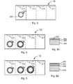
- FIGS. 2A through 2Dare simplified cross section views of a shaped substrate according to one or more embodiments of the present invention.
- FIG. 3is a simplified diagram illustrating a tubular shaped substrate being loaded in a chamber for fabricating thin film solar cell according to an embodiment of the present invention
- FIG. 4is simplified diagram illustrating a tubular shaped substrate being loaded in a chamber for fabricating thin film solar cell according to an embodiment of the present invention and FIG. 4A is an enlarged view of a section of the substrate with an overlying electrode layer;
- FIG. 5is simplified diagram illustrating a tubular shaped substrate being loaded in a chamber for fabricating thin film solar cell according to an embodiment of the present invention and FIG. 5A is an enlarged view of a section of the substrate with an overlying precursor layer on the electrode layer;
- FIG. 6is simplified diagram illustrating a tubular shaped substrate being loaded in a chamber for fabricating thin film solar cell according to an embodiment of the present invention and FIG. 6A is an enlarged view of a section of the substrate with an overlying sodium bearing layer on the precursor layer;
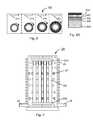
- FIG. 7is simplified diagram illustrating a plurality of tubular shaped substrates being loaded in a chamber for a thermal selenization and sulfurization process according to an embodiment of the present invention
- FIG. 8is simplified diagram illustrating an enlarged section view of a shaped substrate including a CIGS/CIS film after a thermal selenization and sulfurization process according to an embodiment of the present invention
- FIG. 9is schematic diagram illustrating that additional layers are formed overlying the CIGS/CIS film and patterned for building a photovoltaic device according to certain embodiments of the present invention.
- the present inventionrelates generally to photovoltaic techniques. More particularly, embodiments of the present invention provide a method and system for sodium doping in fabricating a copper indium diselenide species (CIS), copper indium gallium diselenide species (CIGS) based thin film photovoltaic cell, and/or others.
- CIScopper indium diselenide species
- CGScopper indium gallium diselenide species
- the inventioncan be applied to various shaped cells including cylindrical/tubular photovoltaic modules, non-planar surfaces, flexible foils, plastics, building or window glass, roof tiles, automobiles, and other combinations.
- FIG. 1is a simplified flowchart illustrating a method of fabricating a thin film photovoltaic cell including in-chamber sodium doping according to an embodiment of the present invention. This diagram is merely an example, which should not unduly limit the scope of the claims herein.
- the method 1000includes the following processes:
- Process 1050 for forming one or more precursor layers on the sodium bearing layercomprising at least a copper and/or copper-gallium layer followed by an indium layer;
- the above sequence of processesprovides a method of forming a Copper-Indium-Diselenide based chalcopyrite absorber layer in a thin film photovoltaic cell according to an embodiment of the present invention.
- the methodincludes an in-chamber sodium doping process of forming a sodium bearing layer over and/or under or in-between one or more precursor layers before performing a thermal treatment selenization and sulfurization process.
- the methodalso includes performing one or more sputtering processes in a same chamber with single or separate compartment for forming one or more layers including, for example, a barrier layer, an electrode layer, sodium bearing layer, one or more precursor layers.
- the sodium bearing layercan be performed using a salt spray process.
- a salt dipping processcan be used for forming the sodium bearing layer overlying an electrode layer or a copper-gallium layer.
- a shaped substrateis provided.
- the shaped substratecan have a spatial form selected from a tube, a cylinder, a sphere, or other non-planar shaped tile, or a flexible foil, a sheet, or a plastic, or polymer and other combinations.
- the shaped substrateis transparent, and preferably a glass.
- the shaped substrateis a soda lime glass, or a borosilicate glass, an acrylic glass, a specialty CorningTM glass, and others like a polymer or a plastic.
- FIGS. 2A through 2DSome examples of the shaped substrates 200 , 200 ′, 200 A, 200 B, are shown in FIGS. 2A through 2D .
- Each of the shaped substratehas a corresponding surface region 201 .
- FIG. 3is a simplified diagram illustrating a tubular shaped substrate being loaded in a chamber for fabricating thin film solar cell according to an embodiment of the present invention.
- This diagramis merely an example, which should not unduly limit the scope of the claims herein.
- a tubular shaped substrate 308is loaded into a chamber 10 .
- the chamber 10is a vacuum chamber configured to perform multiple deposition processes and have various functions.
- chamber 10has one or more targets 311 , 313 , 315 , 317 etc. mounted according to specific manufacture batch system. Each of these targets ( 313 through 317 ) may be disposed in a separate compartment within the chamber 10 .
- each of the one or more targetsis associated with a sputtering process, or more generally, a physical vapor deposition (PVD) process, or simply an evaporation process to deposit one or multiple layers of specific materials therefrom.
- PVDphysical vapor deposition
- the material species of the targetis deposited onto the shaped substrate if the latter is exposed under the corresponding target within the chamber 10 .
- the shaped substrate 308is configured to be manipulated by a tool to allow its surface 301 being fully exposed to the target (for example target 311 ) through one or more mechanical motions.
- the mechanical motionis a rotation, illustrated by the arrow 320 , for the tubular or cylindrical shaped substrate 308 .
- the corresponding mechanical motion 320may be a 3 D rotation, or a 2 D rotation with 360 degrees, or axial rotation with 180 degrees or less.
- the corresponding mechanical motionmay be a deterring, a shifting, a shaking, etc.
- the mechanical motion associating with the shaped substrate for allowing full exposure of its surface region to the material flux from targetsshould be in effect within each compartment during each sputtering process or other type of PVD deposition/evaporation process.
- the shaped substrate 308is made of a soda lime glass.
- the soda lime glassnaturally contains alkaline ions (e.g., Na + ) which can provide a positive influence on the grain growth of thin film photovoltaic materials thereon.
- alkaline ionse.g., Na +
- polycrystalline semiconductor films of CuIn(Ga)Se 2 (CIGS) or CuInSe 2 (CIS) materialscan be formed on soda lime glass substrates with coarse grain sizes of a few microns or larger so that high cell current can be collected with these photovoltaic films to have light-conversion efficiencies of 17% or above.
- the method 1000includes Process 1020 to form a barrier layer overlying the surface region of the shaped substrate.
- This processcan be at least partially illustrated in FIG. 4 and FIG. 4A .
- the barrier layer 306can be formed over the surface region 301 of the shaped substrate 308 .
- the formation processcan be a sputtering process from target 311 or using other deposition process such as PVD, MOCVD, or evaporation.
- the barrier layercan be made from silicon oxide, silicon nitride, titanium nitride and others. Especially for substrate made by soda lime glass, the barrier layer can prevent un-controlled sodium species diffused into the film grown thereon.
- the barrier layeralso serves adhesion enhancement function for the film formed on top of it overlying the surface region of the substrate.
- the barrier layercan have a thickness of about 500 Angstroms, or 1000 Angstroms, or 1 ⁇ m, or 5 ⁇ m, and others.
- the barrier layercan have a thickness of about 500 Angstroms, or 1000 Angstroms, or 1 ⁇ m, or 5 ⁇ m, and others.
- the method 1000includes Process 1030 to form an electrode layer overlying the barrier layer.
- This processcan be at least partially illustrated in FIG. 4 and FIG. 4A .
- the electrode layercan be formed using a sputtering process from a target 313 within the chamber 10 .
- the chamber 10can be installed multiple targets which can be interchangeable for depositing different material species separately and/or depositing several material species simultaneously.
- the target 313 in association with the chamber 10comprises desired metal material or conductive oxide material for forming the electrode layer.
- the target 313comprises molybdenum material and is used to deposit the electrode layer 304 overlying the barrier layer 306 .
- a sodium bearing layermay be added to follow the electrode layer formation.
- a sodium bearing layeris deposited by sputtering from a Mo—Na compound target.
- the molybdenum layeralso can be pre-coated on the commercially available soda lime glass.
- the electrode layer 304is formed on a tubular shaped substrate 308 made by an uncoated and pre-washed soda lime glass using one or more deposition processes.
- the chamber 10is a vacuum chamber configured to load one or more shaped substrates (each is similar to the substrate 308 ) to perform the one or more deposition processes.
- the chamber 10can be one part of a large scale batch system for manufacturing thin film solar cells.
- the electrode layer 304 mentioned abovefunctionally serves a lower or back electrode for a thin film photovoltaic cell formed thereafter on the substrate 308 .
- the electrode layer 304namely a first electrode layer, includes molybdenum material with a bi-layer structure (not explicitly shown in FIG. 4A ).
- a first molybdenum layeris formed overlying the barrier layer 306 on the soda lime glass based shaped substrate 308 using a sputtering process at relative lower pressure of about 2 millitorr.
- the first (or lower) molybdenum layeris substantially under a tensile stress.
- a second (or upper) molybdenum layeris formed overlying the first molybdenum layer using a sputtering process at relative higher pressure of about 20 millitorr.
- the second molybdenum layeris substantially under a compressive stress and has a thickness of about 2000 Angstroms or about ten times thicker than the first molybdenum layer.
- Such bi-layer molybdenum structure with a desired strain fieldprovides benefit of using a laser patterning process to form certain patterns substantially free of film cracking.
- the laser patterning processcan be one of a plurality of processes performed within the same batch system.
- the first electrode layer with a plurality of patterns suitable for corresponding interconnect structurescan be prepared before subsequent processes of manufacturing thin film photovoltaic cells using large scale batch system.
- the method 1000further includes a process (Process 1040 ) of forming a sodium bearing layer overlying the electrode layer.
- This processcan be illustrated by the FIG. 5 and FIG. 5A .
- target 315can contain sodium species uniformly distributed within a host material.
- the sodium bearing layer 302is formed by using a sputtering process from the sodium bearing target, e.g., the target 315 .
- the sodium sputteringcan be performed in a separated compartment of a same chamber (chamber 10 ).
- the substrate 308 with an overlying barrier layer 306 and an electrode layer 304can be transferred from a first compartment in chamber 10 to a second compartment in chamber 10 without breaking vacuum condition but maintaining the sodium bearing layer 302 substantially free from moisture.
- Chamber 10can be held in a high vacuum condition with a pressure set to be smaller than 10 ⁇ 3 microbar.
- Chamber 10can be further supported by a cryogenic pump or a polycold system for attracting water vapor.
- the polycold systemhas an enclosed tube passing through the chamber with very cold fluid to allow cold tube surface to absorb moisture in the chamber, and further reduce the pressure.
- the sputtering process for sodium dopinguses a sodium bearing target with a uniform composition of the sodium species distributed within the host material.
- the shaped substrate 308is configured to fully expose the electrode layer 304 to the target 313 for forming the sodium bearing layer 302 .
- the sodium bearing layeris characterized by a first amount of sodium species that is predetermined for fabricating an absorber layer. The first amount of sodium species at least partially contributes to the final sodium concentration of the absorber layer.
- FIG. 1also shows that the method 1000 includes a process (Process 1050 ) of forming one or more precursor layers overlying the sodium bearing layer.
- the one or more precursor layersat least include a copper layer or a copper-gallium alloy layer, and an indium layer.
- the process 1050can be illustrated by FIG. 6 and FIG. 6A .
- the shaped substrate 308 with an overlying barrier layer 306 followed by the electrode layer 304 and overlying sodium bearing layer 302is exposed to one or more targets from which one or more sputtering processes within the chamber 10 (or maybe in one specific compartment) can be performed to form the one or more precursor layers 301 .
- These diagramsare merely examples, which should not unduly limit the scope of the claims herein.
- One of ordinary skill in the artwould recognize many variations, alternatives, and modifications.
- a copper or a copper-gallium layercan be formed over the sodium bearing layer 302 by sputtering from a corresponding target (for example target 317 ) bearing copper or copper-gallium alloy species.
- the copper or copper-gallium layercan be formed in a two or more stages, each stage representing one sublayer of Cu or Cu—Ga alloy. Between the sublayers, a sodium bearing layer with a second amount of sodium species can be inserted.
- the sodium bearing target and the Cu—Ga targetmay be interchangeable to allow the sequential sputtering processes to perform within the same chamber.
- a DC magnetron sputtering processcan be used to deposit the copper (or Cu—Ga) layer onto the first electrode layer under a following condition.
- the deposition pressure (using Ar gas) in the chamber 10is controlled to be about 2-7 mTorr.
- Argon gas flow ratecan set to grow the layer in a desired deposition rate.
- the full deposition time for sputter depositing a thin sodium bearing layer and a copper (or Cu—Ga) layeris about 30 seconds or less for about 170-180 nm in film thickness.
- the deposition temperaturecan be just at room temperature without need of intentionally heating the substrate. Of course, minor heating may be resulted due to the plasma generated during the deposition.
- the shaped substrate 308is held at a temperature less than 200° C.
- the thin layer of gallium-bearing materialcan be formed by sputtering a gallium-bearing target within an environment provided with argon gas.
- the sputtering processmay use a power of about 120 Watts DC for about ten seconds and less according to a specific embodiment.
- the argon gasis provided at about a suitable flow rate.
- the deposition processis maintained in a vacuum environment, which is about 5 mTorr and less or about 1 mTorr to about 42 mTorr.
- the gallium-bearing target materiale.g., Cu—Ga, or Ga—S target
- the deposition processcan be performed under suitable temperatures such as about 50° C. to about 110° C. or at least less than 200° C. according to a specific embodiment.
- the copper-gallium target used for this sputtering processcan be pre-selected to have a copper content richer than gallium content.
- the copper contentcan be in a range from a determined amount of balance the gallium species or combination of other species.
- the process 1050includes using sputtering deposition to form an indium layer overlying the copper layer or copper-gallium layer formed earlier.
- the indium layercan be formed using a sputtering process that is carried out in a same chamber 10 for performing other sputtering process (with the target 317 now being replaced by a target bearing pure indium species).
- the sputtering process for depositing indium speciescan be performed in a separate compartment within the same chamber or interchange the suitable target within a controlled vacuum environment.
- the indium layeris deposited over the copper layer or copper-gallium layer using a DC magnetron sputtering process under a similar condition. Due to different sputtering rate, the deposition time for the indium layer may be shorter than that for copper (and gallium) layer. For example, 50 to 70 seconds may be enough for depositing an indium layer of about 290 nm in thickness. In another specific embodiment, indium layer may be inserted between sublayers of Cu—Ga layer mentioned earlier. In one or more embodiments, an atomic ratio for copper species over group III species (gallium, indium, sulfur) species can be monitored during the formation of the one or more precursor layers.
- the copper-to-group III species ratiois controlled to be substantially equal to but less than 1.0. This is aimed to have a desired copper:(gallium)indium atomic ratio in the final composition of the absorber layer so that a chalcopyrite CIGS/CIS film with desired grain structure can be formed.
- the sodium bearing layer 302is formed on top of the electrode layer 304 and under the precursor layers 301 , as shown in FIG. 6A .
- the sodium bearing layercan also be overlying the precursor layers or within the precursor layers or any combination of spatial locations.
- the sputtering process for depositing indium speciescan be performed before the sputtering process for depositing copper layer.
- the sodium bearing layer 302is added overlying the indium layer, followed by a copper or copper-gallium layer. In this case, the sodium bearing layer 302 becomes part of or is embedded in the precursor layers 301 .
- a thin film structure including sodium bearing species embedded in the precursor layercan help to prevent or at least substantially reduce the chance for sodium species to absorb ambient humidity which may cause some reactive film damage or even delamination to the interface between the electrode layer 304 , e.g., a molybdenum layer, and the precursor layers 301 .
- using sputtering process as an in-chamber sodium dopingprovides a well controlled stoichiometry for transforming the one or more precursor layers into a desired chalcopyrite structured CIGS/CIS absorber layer.
- a thermal selenization and sulfurization treatmentis carried out for transforming the one or more precursor layers with proper amount of sodium species into an absorber layer for fabricating solar cells. More details can be found in the description below.
- the method 1000includes a process (Process 1060 ) of transferring the shaped substrate from the first chamber to a second chamber.
- the process of transferring the plurality of the (substantially the same) shaped substratesshould be ensured that the copper-indium based precursor layers on each substrate are not exposed to moisture with humidity higher than 10% RH.
- the first chamber 10 , the second chamber 20including some transferring tools, each can be configured independently or to be parts of a same large scale batch system.
- the first chamber 10 and the second chamber 20are directly linked.
- the first chamber 10 and the second chamberare separated.
- the plurality of the shaped substratesare loaded into the chamber 20 in a vertical direction with respect to gravity. In other implementation, the plurality of the shaped substrates can be loaded in horizontal direction with respect to the floor.
- the method 1000further includes a process (Process 1070 ) of subjecting the shaped substrate, including all the deposited films, to a thermal treatment process to transform the one or more precursor layers to a photovoltaic absorber layer with chalcopyrite structure.
- a processProcess 1070
- FIG. 7is simplified diagram illustrating a plurality of tubular shaped substrates being loaded in a chamber for a thermal selenization and sulfurization process according to an embodiment of the present invention. This diagram is merely an example, which should not unduly limit the scope of the claims herein.
- One of ordinary skill in the artwould recognize many variations, alternatives, and modifications.
- the chamber 20is a thermal diffusion furnace or a rapid temperature processor or a thermal annealing chamber with capability of controlling its chamber pressure, ramping and maintaining temperature, heating/cooling the substrate, supplying working gas and carrier gas and pumping out one or more gas species.
- a plurality of heating elements 25are coupled to the chamber 20 from outside to supply thermal power to the inside of chamber 20 to heat the plurality of shaped substrates 700 .
- the chamber 20is coupled to a gas supply device 28 to introduce one or more working gas and carrier gas to establish a gaseous environment 27 at a controlled pressure and compositions.
- the working gas in one processis hydrogen selenide or elemental selenium gas.
- the working gasmay be hydrogen sulfide while selenium species being removed substantially.
- one or more types of carrier gasessuch as nitrogen or other inert gases (argon or helium) are supplied to provide desired pressure and thermal uniformity through the whole volume of the chamber 20 .
- the chamber 20is coupled to a pumping system 29 to control the chamber pressure and selectively remove certain gas species when necessary. Mass spectroscopy tool may be used to monitor the composition of the gas species within the gaseous environment.
- the chamber 20is configured to load a plurality of the tubular shaped substrates, e.g., the substrates 700 , aligning their lengths in a vertical direction with respect to the gravity.
- the tubular shaped substratesnumbered from 1 to N, where N is an integer greater than 2, is held by a substrate holder with a top fixer 22 A and bottom support 22 B.
- the plurality of tubular shaped substratescomprises 4 or more individual substrates, each substrate 700 may be substantially the same as the structure 308 in a cylindrical tube form.
- the plurality number Ncan be 40 or more for one chamber.
- Each substratecan have shapes selected from cylinder, sphere, tubular, semi-cylindrical tile, flexible foil, etc.
- each substrateis a cylindrical tube having an OD ranging from 6 mm to 14 mm. But it is understood that other dimensions are possible.
- Each of the plurality substrates 700is maintained by a holder in a configuration substantially free from warp, or stress, or damage. For example, if the substrates were provided in an orientation vertical with respect to gravity so that the gravitational force could not cause the substrates to sag and warp but to help them to be naturally relaxed or stabilized.
- substrate materialmay reach a glass softening temperature, compromising the structural integrity of the substrate.
- glass substratesparticular soda lime glass substrates, begin to soften at 480° C.
- the shaped substrates 700are also separated from one another according to a predetermined spacing to ensure even heating and reactions with gaseous species that are to be introduced to the furnace.
- a typical rod-to-rod spacingshould be at least 6 mm when the process chamber is fully loaded.
- the thermal treatment process 1070is carried at a variable temperature environment capable ramping up from room temperature to about 450 Degree Celsius.
- the chamber 20is configured to be a diffusion furnace capable of ramping up the temperature with a desired rate and control the temperature to a suitable range with an accuracy of about ⁇ a few degrees.
- the chamber 20is a custom designed rapid thermal processor.
- the thermal treatment process 1070is a thermal selenization process carried out in an environment comprising a gaseous selenium-bearing material.
- the gaseous selenium bearing materialcan be a gas-phase elemental selenium (or selenium vapor).
- hydrogen selenide H 2 Se gasis used.
- the thermal treatmentis substantially a reactive annealing and diffusion process.
- Nitrogen gasis also added as a carrier gas for adjusting chamber pressure to about 600 Torr during the treatment for enhancing thermal uniformity within the diffusion furnace. In one implementation for large batch system, custom temperature profile needs to be obtained.
- the thermal treatment process 1070usually begins at room temperature with a certain composition of hydrogen selenide gas mixed with nitrogen gas provided into the diffusion furnace 30 .
- the temperatureis ramped up to about 400 ⁇ 10 Degrees Celsius at the same composition of gaseous environment, then the temperature is maintained there for a period of time of about 10 minutes to one hour.
- the selenium based working gasis pumped out to substantially remove selenium species in the chamber to stop the reactive process.
- the thermal treatment processcontinues as a sulfurization process as hydrogen sulfide H 2 S gas is added in as working gas before the temperature is further ramped up to about 500 degree Celsius or even higher.
- nitrogen gasalso is added as a carrier gas for keeping glass substrates at a substantially uniform temperature. Adding H 2 S gas can help to extract/replace certain amount of selenium species from the precursor layer to change band structure and optical profile of the photovoltaic absorber layer to create higher open circuit voltage.
- a copper-indium(gallium)-diselenide CuIn(Ga)Se 2 (CIGS/CIS) film in chalcopyrite structureis formed from the one or more precursor layers deposited at the first stage of the two-stage process.
- the first amount of sodium doped over the first electrode layer plus optionally the second amount of sodium deposited in between the one or more precursor layersare combined to contribute the thermal-induced reaction which leads to relative large CIGS/CIS chalcopyrite grains.
- FIG. 8shows an enlarged section view of a shaped substrate including the chalcopyrite CIGS/CIS film after the thermal selenization and sulfurization process according to an embodiment of the present invention.
- the formed CIGS/CIS film 800 as a photovoltaic absorber layeroverlays the electrode layer 806 of the shaped substrate 808 .
- the atomic ratio of Cu-to-group III speciesis controlled to be slightly less than 1.0 and the sodium content is about 5 ⁇ 10 19 atom/cm 3 in order to achieve a desired structural property leading to high device performance as a photovoltaic absorber layer.
- the formation of CIGS/CIS chalcopyrite absorber layer 800is carried out after performing the in-chamber sodium doping process.
- the sodium bearing layer 302 with a controlled amountplays a role in helping the growth of polycrystalline chalcopyrite structured grains in the formed precursor layer during the thermal treatment process 1070 .
- the sodium species under a controlled concentrationhelps the chalcopyrite grains in film 800 to grow in relative large size up to a few microns. Without the assistance of sodium atoms or with non-controlled excessive supply of sodium content, the chalcopyrite grains in film 800 would become substantially finer, leading to a great reduction in photovoltaic current and degradation of the efficiency of the solar device.
- the sodium contentcan be well controlled by the in-chamber sodium doping process, which is simply a sputtering process using a sodium bearing target with a uniform composition of the sodium species distributed within a host material.
- a preferred sodium concentration within the chalcopyrite CIGS/CIS photovoltaic absorber layeris about 5 ⁇ 10 19 atom/cm 3 .
- sodium dopingcan also be carried out by a salt spraying process or a salt dipping process.
- the thermal treatment process 1070can be also a sulfidation process alone where the chamber 20 is held in an environment with a fluidic-phase sulfur bearing species.
- the sulfur bearing speciescan be provided in a solution, which has dissolved Na 2 S, CS 2 , (NH 4 ) 2 S, thiosulfate, and others.
- the sulfur bearing speciescan be hydrogen sulfide in gas phase.
- the thermal treatment processwould cause reaction between the selenium/sulfur and the deposited composite film including copper, indium, gallium, and sodium.
- the reactionunder a suitable condition at least leads to a formation of the film 800 that contains a plurality of chalcopyrite structured grains.
- the method 1000can include one or more processes 1080 that are required for fabricating a thin film solar cells on the shaped substrate.
- the method 1000may include a process of forming a cadmium sulfide layer as a window layer 900 overlying the chalcopyrite photovoltaic absorber layer 800 .
- FIG. 9shows an example that additional layers are formed overlying the CIGS/CIS film and patterned for building a photovoltaic device according to certain embodiments of the present invention.
- the cadmium sulfide layeris characterized as a wide bandgap semiconductor for the thin film photovoltaic cells formed thereafter.
- the cadmium sulfide layercan be formed using sputtering, vacuum evaporation, or chemical bath deposition (CBD) techniques and doped with n + -type impurities for conductivity.
- the window layer 900can be selected from a group materials consisting of a cadmium sulfide (CdS), a zinc sulfide (ZnS), zinc selenium (ZnSe), zinc oxide (ZnO), zinc magnesium oxide (ZnMgO), or others.
- an upper electrode layercan be added overlying the window layer.
- the upper electrode layertypically is optically transparent.
- One widely used material for the upper electrode layeris transparent conductive oxide.
- a zinc oxide film characterized with a resistivity of about 2 ⁇ 10 ⁇ 3 Ohm-cm and lessis used.
- a first zinc oxide layerwill be added overlying the window layer.
- a second zinc oxide layeris inserted between the window layer and the first zinc oxide layer.
- the second zinc oxide layerhas a higher resistivity than the first zinc oxide layer.
- the second zinc oxide layerplays more a role of barrier/protection layer while the first zinc oxide layer with lower resistivity plays more a role of conductive electrode layer.
- the zinc oxide layeris formed using a metalorganic chemical vapor deposition (MOCVD) technique within the same large scale batch system.
- the method 1000may include a process of maintaining the transparent substrate including the composite film to an environment substantially free from moisture.
- This processmay be performed after the in-chamber sodium doping process and before the thermal treatment process.
- this processis performed after forming a copper and gallium layer and an indium layer in a first chamber but before transferring into a second chamber for performing sodium doping process.
- this processalso is performed after the formation of copper based chalcopyrite photovoltaic absorber layer but before transferring into diffusion furnace. Due to the specific film composition including copper, gallium, indium, sodium species, exposing the film to moisture may cause serious damage to the grain structure of the film and eventually cause degradation of its photovoltaic efficiency.
- a work piecee.g., the soda lime glass substrate with the overlying composition film or the just formed photovoltaic absorber layer or the absorber layer plus window layer, can be stored in a descicator with a humidity less than 10% RH.
- the work piececan be stored inside an aqueous solution.
Landscapes
- Photovoltaic Devices (AREA)
Abstract
Description
Claims (29)
Priority Applications (1)
| Application Number | Priority Date | Filing Date | Title |
|---|---|---|---|
| US12/774,675US8241943B1 (en) | 2009-05-08 | 2010-05-05 | Sodium doping method and system for shaped CIGS/CIS based thin film solar cells |
Applications Claiming Priority (2)
| Application Number | Priority Date | Filing Date | Title |
|---|---|---|---|
| US17685709P | 2009-05-08 | 2009-05-08 | |
| US12/774,675US8241943B1 (en) | 2009-05-08 | 2010-05-05 | Sodium doping method and system for shaped CIGS/CIS based thin film solar cells |
Publications (1)
| Publication Number | Publication Date |
|---|---|
| US8241943B1true US8241943B1 (en) | 2012-08-14 |
Family
ID=46613444
Family Applications (1)
| Application Number | Title | Priority Date | Filing Date |
|---|---|---|---|
| US12/774,675Expired - Fee RelatedUS8241943B1 (en) | 2009-05-08 | 2010-05-05 | Sodium doping method and system for shaped CIGS/CIS based thin film solar cells |
Country Status (1)
| Country | Link |
|---|---|
| US (1) | US8241943B1 (en) |
Cited By (6)
| Publication number | Priority date | Publication date | Assignee | Title |
|---|---|---|---|---|
| US20120302002A1 (en)* | 2011-08-15 | 2012-11-29 | Stion Corporation | Method of Manufacture of Sodium Doped CIGS/CIGSS Absorber Layers for High Efficiency Photovoltaic Devices |
| US20170069498A1 (en)* | 2015-09-08 | 2017-03-09 | The Regents Of The University Of California | Surface doping of nanostructures |
| CN108321075A (en)* | 2017-12-15 | 2018-07-24 | 米亚索乐装备集成(福建)有限公司 | The preparation method of CIGS thin film solar cell |
| CN110079767A (en)* | 2019-04-26 | 2019-08-02 | 潮州市亿加光电科技有限公司 | Target, back electrode layer preparation method and the CIGS solar battery of doping metals Na |
| US20210167235A1 (en)* | 2019-12-03 | 2021-06-03 | Applied Materials, Inc. | Copper, indium, gallium, selenium (cigs) films with improved quantum efficiency |
| CN113036000A (en)* | 2021-02-24 | 2021-06-25 | 深圳先进技术研究院 | Preparation method of broadband near-infrared detector and broadband near-infrared detector |
Citations (89)
| Publication number | Priority date | Publication date | Assignee | Title |
|---|---|---|---|---|
| US4204933A (en) | 1977-11-15 | 1980-05-27 | Imperial Chemical Industries Limited | Electrocoating process for producing a semiconducting film |
| US4213781A (en) | 1978-11-20 | 1980-07-22 | Westinghouse Electric Corp. | Deposition of solid semiconductor compositions and novel semiconductor materials |
| US4239553A (en) | 1979-05-29 | 1980-12-16 | University Of Delaware | Thin film photovoltaic cells having increased durability and operating life and method for making same |
| US4347436A (en) | 1979-03-26 | 1982-08-31 | Canon Kabushiki Kaisha | Photoelectric transducing element with high polymer substrate |
| US4502225A (en) | 1983-05-06 | 1985-03-05 | Rca Corporation | Mechanical scriber for semiconductor devices |
| US4611091A (en) | 1984-12-06 | 1986-09-09 | Atlantic Richfield Company | CuInSe2 thin film solar cell with thin CdS and transparent window layer |
| US4612411A (en) | 1985-06-04 | 1986-09-16 | Atlantic Richfield Company | Thin film solar cell with ZnO window layer |
| US4873118A (en) | 1988-11-18 | 1989-10-10 | Atlantic Richfield Company | Oxygen glow treating of ZnO electrode for thin film silicon solar cell |
| US4915745A (en) | 1988-09-22 | 1990-04-10 | Atlantic Richfield Company | Thin film solar cell and method of making |
| US4996108A (en) | 1989-01-17 | 1991-02-26 | Simon Fraser University | Sheets of transition metal dichalcogenides |
| US5125984A (en) | 1990-05-31 | 1992-06-30 | Siemens Aktiengesellschaft | Induced junction chalcopyrite solar cell |
| US5261968A (en) | 1992-01-13 | 1993-11-16 | Photon Energy, Inc. | Photovoltaic cell and method |
| US5421909A (en) | 1992-03-03 | 1995-06-06 | Canon Kabushiki Kaisha | Photovoltaic conversion device |
| US5482571A (en) | 1993-06-14 | 1996-01-09 | Canon Kabushiki Kaisha | Solar cell module |
| US5501744A (en) | 1992-01-13 | 1996-03-26 | Photon Energy, Inc. | Photovoltaic cell having a p-type polycrystalline layer with large crystals |
| US5536333A (en) | 1992-05-12 | 1996-07-16 | Solar Cells, Inc. | Process for making photovoltaic devices and resultant product |
| US5578103A (en) | 1994-08-17 | 1996-11-26 | Corning Incorporated | Alkali metal ion migration control |
| US5589006A (en) | 1993-11-30 | 1996-12-31 | Canon Kabushiki Kaisha | Solar battery module and passive solar system using same |
| US5622634A (en) | 1993-12-17 | 1997-04-22 | Canon Kabushiki Kaisha | Method of manufacturing electron-emitting device, electron source and image-forming apparatus |
| US5626688A (en) | 1994-12-01 | 1997-05-06 | Siemens Aktiengesellschaft | Solar cell with chalcopyrite absorber layer |
| US5665175A (en) | 1990-05-30 | 1997-09-09 | Safir; Yakov | Bifacial solar cell |
| US5855974A (en) | 1993-10-25 | 1999-01-05 | Ford Global Technologies, Inc. | Method of producing CVD diamond coated scribing wheels |
| US5948176A (en) | 1997-09-29 | 1999-09-07 | Midwest Research Institute | Cadmium-free junction fabrication process for CuInSe2 thin film solar cells |
| US5985691A (en) | 1997-05-16 | 1999-11-16 | International Solar Electric Technology, Inc. | Method of making compound semiconductor films and making related electronic devices |
| US6001744A (en) | 1996-08-30 | 1999-12-14 | Sumitomo Electric Industries, Ltd. | Method of cleaning a surface of a compound semiconductor crystal of group II-VI elements of periodic table |
| US6077722A (en) | 1998-07-14 | 2000-06-20 | Bp Solarex | Producing thin film photovoltaic modules with high integrity interconnects and dual layer contacts |
| US6134049A (en) | 1998-09-25 | 2000-10-17 | The Regents Of The University Of California | Method to adjust multilayer film stress induced deformation of optics |
| US6169246B1 (en) | 1998-09-08 | 2001-01-02 | Midwest Research Institute | Photovoltaic devices comprising zinc stannate buffer layer and method for making |
| US6258620B1 (en) | 1997-10-15 | 2001-07-10 | University Of South Florida | Method of manufacturing CIGS photovoltaic devices |
| US6310281B1 (en) | 2000-03-16 | 2001-10-30 | Global Solar Energy, Inc. | Thin-film, flexible photovoltaic module |
| US6328871B1 (en) | 1999-08-16 | 2001-12-11 | Applied Materials, Inc. | Barrier layer for electroplating processes |
| US6335479B1 (en) | 1998-10-13 | 2002-01-01 | Dai Nippon Printing Co., Ltd. | Protective sheet for solar battery module, method of fabricating the same and solar battery module |
| US20020004302A1 (en) | 1995-09-14 | 2002-01-10 | Yoshihiko Fukumoto | Method for fabricating semiconductor device |
| US6361718B1 (en) | 1998-02-05 | 2002-03-26 | Nippon Sheet Glass Co., Ltd. | Article having uneven surface, production process for the article, and composition for the process |
| US6380480B1 (en) | 1999-05-18 | 2002-04-30 | Nippon Sheet Glass Co., Ltd | Photoelectric conversion device and substrate for photoelectric conversion device |
| US20020061361A1 (en) | 2000-09-06 | 2002-05-23 | Hiroki Nakahara | Method and apparatus for fabricating electro-optical device and method and apparatus for fabricating liquid crystal panel |
| US6423565B1 (en) | 2000-05-30 | 2002-07-23 | Kurt L. Barth | Apparatus and processes for the massproduction of photovotaic modules |
| US6537845B1 (en) | 2001-08-30 | 2003-03-25 | Mccandless Brian E. | Chemical surface deposition of ultra-thin semiconductors |
| US6632113B1 (en) | 1998-09-09 | 2003-10-14 | Canon Kabushiki Kaisha | Image display apparatus, disassembly processing method therefor, and component recovery method |
| US6635307B2 (en) | 2001-12-12 | 2003-10-21 | Nanotek Instruments, Inc. | Manufacturing method for thin-film solar cells |
| US20040191950A1 (en) | 2003-03-26 | 2004-09-30 | Canon Kabushiki Kaisha | Method of producing photovoltaic device |
| US20040191949A1 (en) | 2003-03-25 | 2004-09-30 | Canon Kabushiki Kaisha | Zinc oxide film treatment method and method of manufacturing photovoltaic device utilizing the same |
| US20050109392A1 (en) | 2002-09-30 | 2005-05-26 | Hollars Dennis R. | Manufacturing apparatus and method for large-scale production of thin-film solar cells |
| US20050223570A1 (en) | 2002-09-26 | 2005-10-13 | Honda Giken Kogyo Kabushiki Kaisha | Mechanical scribing apparatus with controlling force of a scribing cutter |
| US20060219288A1 (en) | 2004-11-10 | 2006-10-05 | Daystar Technologies, Inc. | Process and photovoltaic device using an akali-containing layer |
| US20060220059A1 (en) | 2003-04-09 | 2006-10-05 | Matsushita Electric Industrial Co., Ltd | Solar cell |
| US20070004078A1 (en) | 2003-08-14 | 2007-01-04 | Vivian Alberts | Method for the preparation of group ib-iiia-via quaternary or higher alloy semiconductor films |
| US7179677B2 (en) | 2003-09-03 | 2007-02-20 | Midwest Research Institute | ZnO/Cu(InGa)Se2 solar cells prepared by vapor phase Zn doping |
| US20070089782A1 (en) | 2003-10-02 | 2007-04-26 | Scheuten Glasgroep | Spherical or grain-shaped semiconductor element for use in solar cells and method for producing the same; method for producing a solar cell comprising said semiconductor element and solar cell |
| US20070116892A1 (en) | 2005-11-18 | 2007-05-24 | Daystar Technologies, Inc. | Methods and apparatus for treating a work piece with a vaporous element |
| US7235736B1 (en) | 2006-03-18 | 2007-06-26 | Solyndra, Inc. | Monolithic integration of cylindrical solar cells |
| US20070151596A1 (en) | 2004-02-20 | 2007-07-05 | Sharp Kabushiki Kaisha | Substrate for photoelectric conversion device, photoelectric conversion device, and stacked photoelectric conversion device |
| US20070169810A1 (en) | 2004-02-19 | 2007-07-26 | Nanosolar, Inc. | High-throughput printing of semiconductor precursor layer by use of chalcogen-containing vapor |
| US7252923B2 (en) | 2001-10-16 | 2007-08-07 | Dai Nippon Printing Co., Ltd. | Methods for producing pattern-forming body |
| US20070209700A1 (en) | 2004-04-28 | 2007-09-13 | Honda Motor Co., Ltd. | Chalcopyrite Type Solar Cell |
| US20070243657A1 (en) | 2006-04-13 | 2007-10-18 | Basol Bulent M | Method and Apparatus to Form Thin Layers of Materials on a Base |
| US7303788B2 (en) | 2003-03-24 | 2007-12-04 | Canon Kabushiki Kaisha | Method for manufacturing solar cell module having a sealing resin layer formed on a metal oxide layer |
| US7319190B2 (en) | 2004-11-10 | 2008-01-15 | Daystar Technologies, Inc. | Thermal process for creation of an in-situ junction layer in CIGS |
| US20080041446A1 (en) | 2006-08-09 | 2008-02-21 | Industrial Technology Research Institute | Dye-sensitized solar cells and method for fabricating same |
| US20080092945A1 (en) | 2006-10-24 | 2008-04-24 | Applied Quantum Technology Llc | Semiconductor Grain and Oxide Layer for Photovoltaic Cells |
| US20080092953A1 (en) | 2006-05-15 | 2008-04-24 | Stion Corporation | Method and structure for thin film photovoltaic materials using bulk semiconductor materials |
| US7364808B2 (en) | 2001-10-19 | 2008-04-29 | Asahi Glass Company, Limited | Substrate with transparent conductive oxide film, process for its production and photoelectric conversion element |
| US20080115827A1 (en) | 2006-04-18 | 2008-05-22 | Itn Energy Systems, Inc. | Reinforcing Structures For Thin-Film Photovoltaic Device Substrates, And Associated Methods |
| US20080121277A1 (en) | 2004-02-19 | 2008-05-29 | Robinson Matthew R | High-throughput printing of semiconductor precursor layer from chalcogenide microflake particles |
| US20080210303A1 (en) | 2006-11-02 | 2008-09-04 | Guardian Industries Corp. | Front electrode for use in photovoltaic device and method of making same |
| US20080216886A1 (en) | 2005-07-01 | 2008-09-11 | Tadashi Iwakura | Solar Cell Module |
| US20090021157A1 (en) | 2007-07-18 | 2009-01-22 | Tae-Woong Kim | Organic light emitting display and method of manufacturing the same |
| US20090087942A1 (en) | 2005-08-05 | 2009-04-02 | Meyers Peter V | Manufacture of Photovoltaic Devices |
| US20090084438A1 (en) | 2006-11-02 | 2009-04-02 | Guardian Industries Corp., | Front electrode for use in photovoltaic device and method of making same |
| US7576017B2 (en) | 2004-11-10 | 2009-08-18 | Daystar Technologies, Inc. | Method and apparatus for forming a thin-film solar cell using a continuous process |
| US20090235987A1 (en) | 2008-03-24 | 2009-09-24 | Epv Solar, Inc. | Chemical Treatments to Enhance Photovoltaic Performance of CIGS |
| US20090235983A1 (en) | 2008-03-18 | 2009-09-24 | Applied Quantum Technology, Llc | Interlayer Design for Epitaxial Growth of Semiconductor Layers |
| US20090293945A1 (en) | 2008-06-02 | 2009-12-03 | Saint Gobain Glass France | Photovoltaic cell and photovoltaic cell substrate |
| US7632701B2 (en)* | 2006-05-08 | 2009-12-15 | University Of Central Florida Research Foundation, Inc. | Thin film solar cells by selenization sulfurization using diethyl selenium as a selenium precursor |
| US20100087016A1 (en) | 2008-04-15 | 2010-04-08 | Global Solar Energy, Inc. | Apparatus and methods for manufacturing thin-film solar cells |
| US20100087027A1 (en) | 2008-09-30 | 2010-04-08 | Stion Corporation | Large Scale Chemical Bath System and Method for Cadmium Sulfide Processing of Thin Film Photovoltaic Materials |
| US20100087026A1 (en) | 2006-12-21 | 2010-04-08 | Helianthos B.V. | Method for making solar sub-cells from a solar cell |
| US20100096007A1 (en) | 2007-07-27 | 2010-04-22 | Saint-Gobain Glass France | Photovoltaic cell front face substrate and use of a substrate for a photovoltaic cell front face |
| US20100101648A1 (en) | 2007-10-19 | 2010-04-29 | Sony Corporation | Dye-sensitized photoelectric conversion device and method of manufacturing the same |
| US20100101649A1 (en) | 2006-11-14 | 2010-04-29 | Saint-Gobain Glass France | Porous layer, its manufacturing process and its applications |
| US7736755B2 (en) | 2005-04-25 | 2010-06-15 | Fujifilm Corporation | Organic electroluminescent device |
| US7741560B2 (en) | 2005-07-22 | 2010-06-22 | Honda Motor Co., Ltd. | Chalcopyrite solar cell |
| US20100212732A1 (en)* | 2009-02-20 | 2010-08-26 | Miasole | Protective layer for large-scale production of thin-film solar cells |
| US20100224247A1 (en) | 2009-03-09 | 2010-09-09 | Applied Quantum Technology, Llc | Enhancement of Semiconducting Photovoltaic Absorbers by the Addition of Alkali Salts Through Solution Coating Techniques |
| US20100267189A1 (en) | 2004-02-19 | 2010-10-21 | Dong Yu | Solution-based fabrication of photovoltaic cell |
| US20100297798A1 (en) | 2006-07-27 | 2010-11-25 | Adriani Paul M | Individually Encapsulated Solar Cells and/or Solar Cell Strings |
| US7846750B2 (en) | 2007-06-12 | 2010-12-07 | Guardian Industries Corp. | Textured rear electrode structure for use in photovoltaic device such as CIGS/CIS solar cell |
| US7863518B2 (en) | 2003-03-20 | 2011-01-04 | Sanyo Electric Co., Ltd. | Photovoltaic device |
| US7875945B2 (en) | 2007-06-12 | 2011-01-25 | Guardian Industries Corp. | Rear electrode structure for use in photovoltaic device such as CIGS/CIS photovoltaic device and method of making same |
- 2010
- 2010-05-05USUS12/774,675patent/US8241943B1/ennot_activeExpired - Fee Related
Patent Citations (95)
| Publication number | Priority date | Publication date | Assignee | Title |
|---|---|---|---|---|
| US4204933A (en) | 1977-11-15 | 1980-05-27 | Imperial Chemical Industries Limited | Electrocoating process for producing a semiconducting film |
| US4213781A (en) | 1978-11-20 | 1980-07-22 | Westinghouse Electric Corp. | Deposition of solid semiconductor compositions and novel semiconductor materials |
| US4347436A (en) | 1979-03-26 | 1982-08-31 | Canon Kabushiki Kaisha | Photoelectric transducing element with high polymer substrate |
| US4239553A (en) | 1979-05-29 | 1980-12-16 | University Of Delaware | Thin film photovoltaic cells having increased durability and operating life and method for making same |
| US4502225A (en) | 1983-05-06 | 1985-03-05 | Rca Corporation | Mechanical scriber for semiconductor devices |
| US4611091A (en) | 1984-12-06 | 1986-09-09 | Atlantic Richfield Company | CuInSe2 thin film solar cell with thin CdS and transparent window layer |
| US4612411A (en) | 1985-06-04 | 1986-09-16 | Atlantic Richfield Company | Thin film solar cell with ZnO window layer |
| US4915745A (en) | 1988-09-22 | 1990-04-10 | Atlantic Richfield Company | Thin film solar cell and method of making |
| US4915745B1 (en) | 1988-09-22 | 1992-04-07 | A Pollock Gary | |
| US4873118A (en) | 1988-11-18 | 1989-10-10 | Atlantic Richfield Company | Oxygen glow treating of ZnO electrode for thin film silicon solar cell |
| US4996108A (en) | 1989-01-17 | 1991-02-26 | Simon Fraser University | Sheets of transition metal dichalcogenides |
| US5665175A (en) | 1990-05-30 | 1997-09-09 | Safir; Yakov | Bifacial solar cell |
| US5125984A (en) | 1990-05-31 | 1992-06-30 | Siemens Aktiengesellschaft | Induced junction chalcopyrite solar cell |
| US5501744A (en) | 1992-01-13 | 1996-03-26 | Photon Energy, Inc. | Photovoltaic cell having a p-type polycrystalline layer with large crystals |
| US5261968A (en) | 1992-01-13 | 1993-11-16 | Photon Energy, Inc. | Photovoltaic cell and method |
| US5421909A (en) | 1992-03-03 | 1995-06-06 | Canon Kabushiki Kaisha | Photovoltaic conversion device |
| US5536333A (en) | 1992-05-12 | 1996-07-16 | Solar Cells, Inc. | Process for making photovoltaic devices and resultant product |
| US5482571A (en) | 1993-06-14 | 1996-01-09 | Canon Kabushiki Kaisha | Solar cell module |
| US5855974A (en) | 1993-10-25 | 1999-01-05 | Ford Global Technologies, Inc. | Method of producing CVD diamond coated scribing wheels |
| US5589006A (en) | 1993-11-30 | 1996-12-31 | Canon Kabushiki Kaisha | Solar battery module and passive solar system using same |
| US5622634A (en) | 1993-12-17 | 1997-04-22 | Canon Kabushiki Kaisha | Method of manufacturing electron-emitting device, electron source and image-forming apparatus |
| US5578103A (en) | 1994-08-17 | 1996-11-26 | Corning Incorporated | Alkali metal ion migration control |
| US5626688A (en) | 1994-12-01 | 1997-05-06 | Siemens Aktiengesellschaft | Solar cell with chalcopyrite absorber layer |
| US20020004302A1 (en) | 1995-09-14 | 2002-01-10 | Yoshihiko Fukumoto | Method for fabricating semiconductor device |
| US6001744A (en) | 1996-08-30 | 1999-12-14 | Sumitomo Electric Industries, Ltd. | Method of cleaning a surface of a compound semiconductor crystal of group II-VI elements of periodic table |
| US5985691A (en) | 1997-05-16 | 1999-11-16 | International Solar Electric Technology, Inc. | Method of making compound semiconductor films and making related electronic devices |
| US5948176A (en) | 1997-09-29 | 1999-09-07 | Midwest Research Institute | Cadmium-free junction fabrication process for CuInSe2 thin film solar cells |
| US6258620B1 (en) | 1997-10-15 | 2001-07-10 | University Of South Florida | Method of manufacturing CIGS photovoltaic devices |
| US6361718B1 (en) | 1998-02-05 | 2002-03-26 | Nippon Sheet Glass Co., Ltd. | Article having uneven surface, production process for the article, and composition for the process |
| US6077722A (en) | 1998-07-14 | 2000-06-20 | Bp Solarex | Producing thin film photovoltaic modules with high integrity interconnects and dual layer contacts |
| US6288325B1 (en) | 1998-07-14 | 2001-09-11 | Bp Corporation North America Inc. | Producing thin film photovoltaic modules with high integrity interconnects and dual layer contacts |
| US6169246B1 (en) | 1998-09-08 | 2001-01-02 | Midwest Research Institute | Photovoltaic devices comprising zinc stannate buffer layer and method for making |
| US6632113B1 (en) | 1998-09-09 | 2003-10-14 | Canon Kabushiki Kaisha | Image display apparatus, disassembly processing method therefor, and component recovery method |
| US6134049A (en) | 1998-09-25 | 2000-10-17 | The Regents Of The University Of California | Method to adjust multilayer film stress induced deformation of optics |
| US6335479B1 (en) | 1998-10-13 | 2002-01-01 | Dai Nippon Printing Co., Ltd. | Protective sheet for solar battery module, method of fabricating the same and solar battery module |
| US6380480B1 (en) | 1999-05-18 | 2002-04-30 | Nippon Sheet Glass Co., Ltd | Photoelectric conversion device and substrate for photoelectric conversion device |
| US6328871B1 (en) | 1999-08-16 | 2001-12-11 | Applied Materials, Inc. | Barrier layer for electroplating processes |
| US6310281B1 (en) | 2000-03-16 | 2001-10-30 | Global Solar Energy, Inc. | Thin-film, flexible photovoltaic module |
| US6423565B1 (en) | 2000-05-30 | 2002-07-23 | Kurt L. Barth | Apparatus and processes for the massproduction of photovotaic modules |
| US7220321B2 (en) | 2000-05-30 | 2007-05-22 | Barth Kurt L | Apparatus and processes for the mass production of photovoltaic modules |
| US20020061361A1 (en) | 2000-09-06 | 2002-05-23 | Hiroki Nakahara | Method and apparatus for fabricating electro-optical device and method and apparatus for fabricating liquid crystal panel |
| US6537845B1 (en) | 2001-08-30 | 2003-03-25 | Mccandless Brian E. | Chemical surface deposition of ultra-thin semiconductors |
| US7252923B2 (en) | 2001-10-16 | 2007-08-07 | Dai Nippon Printing Co., Ltd. | Methods for producing pattern-forming body |
| US7364808B2 (en) | 2001-10-19 | 2008-04-29 | Asahi Glass Company, Limited | Substrate with transparent conductive oxide film, process for its production and photoelectric conversion element |
| US6635307B2 (en) | 2001-12-12 | 2003-10-21 | Nanotek Instruments, Inc. | Manufacturing method for thin-film solar cells |
| US20050223570A1 (en) | 2002-09-26 | 2005-10-13 | Honda Giken Kogyo Kabushiki Kaisha | Mechanical scribing apparatus with controlling force of a scribing cutter |
| US20050109392A1 (en) | 2002-09-30 | 2005-05-26 | Hollars Dennis R. | Manufacturing apparatus and method for large-scale production of thin-film solar cells |
| US7544884B2 (en) | 2002-09-30 | 2009-06-09 | Miasole | Manufacturing method for large-scale production of thin-film solar cells |
| US20090145746A1 (en) | 2002-09-30 | 2009-06-11 | Miasole | Manufacturing apparatus and method for large-scale production of thin-film solar cells |
| US7863518B2 (en) | 2003-03-20 | 2011-01-04 | Sanyo Electric Co., Ltd. | Photovoltaic device |
| US7303788B2 (en) | 2003-03-24 | 2007-12-04 | Canon Kabushiki Kaisha | Method for manufacturing solar cell module having a sealing resin layer formed on a metal oxide layer |
| US20040191949A1 (en) | 2003-03-25 | 2004-09-30 | Canon Kabushiki Kaisha | Zinc oxide film treatment method and method of manufacturing photovoltaic device utilizing the same |
| US20040191950A1 (en) | 2003-03-26 | 2004-09-30 | Canon Kabushiki Kaisha | Method of producing photovoltaic device |
| US20060220059A1 (en) | 2003-04-09 | 2006-10-05 | Matsushita Electric Industrial Co., Ltd | Solar cell |
| US20070004078A1 (en) | 2003-08-14 | 2007-01-04 | Vivian Alberts | Method for the preparation of group ib-iiia-via quaternary or higher alloy semiconductor films |
| US7179677B2 (en) | 2003-09-03 | 2007-02-20 | Midwest Research Institute | ZnO/Cu(InGa)Se2 solar cells prepared by vapor phase Zn doping |
| US20070089782A1 (en) | 2003-10-02 | 2007-04-26 | Scheuten Glasgroep | Spherical or grain-shaped semiconductor element for use in solar cells and method for producing the same; method for producing a solar cell comprising said semiconductor element and solar cell |
| US20100267189A1 (en) | 2004-02-19 | 2010-10-21 | Dong Yu | Solution-based fabrication of photovoltaic cell |
| US20070169810A1 (en) | 2004-02-19 | 2007-07-26 | Nanosolar, Inc. | High-throughput printing of semiconductor precursor layer by use of chalcogen-containing vapor |
| US20080121277A1 (en) | 2004-02-19 | 2008-05-29 | Robinson Matthew R | High-throughput printing of semiconductor precursor layer from chalcogenide microflake particles |
| US20070151596A1 (en) | 2004-02-20 | 2007-07-05 | Sharp Kabushiki Kaisha | Substrate for photoelectric conversion device, photoelectric conversion device, and stacked photoelectric conversion device |
| US20070209700A1 (en) | 2004-04-28 | 2007-09-13 | Honda Motor Co., Ltd. | Chalcopyrite Type Solar Cell |
| US7576017B2 (en) | 2004-11-10 | 2009-08-18 | Daystar Technologies, Inc. | Method and apparatus for forming a thin-film solar cell using a continuous process |
| US7319190B2 (en) | 2004-11-10 | 2008-01-15 | Daystar Technologies, Inc. | Thermal process for creation of an in-situ junction layer in CIGS |
| US20060219288A1 (en) | 2004-11-10 | 2006-10-05 | Daystar Technologies, Inc. | Process and photovoltaic device using an akali-containing layer |
| US7736755B2 (en) | 2005-04-25 | 2010-06-15 | Fujifilm Corporation | Organic electroluminescent device |
| US20080216886A1 (en) | 2005-07-01 | 2008-09-11 | Tadashi Iwakura | Solar Cell Module |
| US7741560B2 (en) | 2005-07-22 | 2010-06-22 | Honda Motor Co., Ltd. | Chalcopyrite solar cell |
| US20090087942A1 (en) | 2005-08-05 | 2009-04-02 | Meyers Peter V | Manufacture of Photovoltaic Devices |
| US20070116892A1 (en) | 2005-11-18 | 2007-05-24 | Daystar Technologies, Inc. | Methods and apparatus for treating a work piece with a vaporous element |
| US7235736B1 (en) | 2006-03-18 | 2007-06-26 | Solyndra, Inc. | Monolithic integration of cylindrical solar cells |
| US20080110491A1 (en) | 2006-03-18 | 2008-05-15 | Solyndra, Inc., | Monolithic integration of non-planar solar cells |
| US20070243657A1 (en) | 2006-04-13 | 2007-10-18 | Basol Bulent M | Method and Apparatus to Form Thin Layers of Materials on a Base |
| US20080115827A1 (en) | 2006-04-18 | 2008-05-22 | Itn Energy Systems, Inc. | Reinforcing Structures For Thin-Film Photovoltaic Device Substrates, And Associated Methods |
| US7632701B2 (en)* | 2006-05-08 | 2009-12-15 | University Of Central Florida Research Foundation, Inc. | Thin film solar cells by selenization sulfurization using diethyl selenium as a selenium precursor |
| US20080092953A1 (en) | 2006-05-15 | 2008-04-24 | Stion Corporation | Method and structure for thin film photovoltaic materials using bulk semiconductor materials |
| US20100297798A1 (en) | 2006-07-27 | 2010-11-25 | Adriani Paul M | Individually Encapsulated Solar Cells and/or Solar Cell Strings |
| US20080041446A1 (en) | 2006-08-09 | 2008-02-21 | Industrial Technology Research Institute | Dye-sensitized solar cells and method for fabricating same |
| US20080092945A1 (en) | 2006-10-24 | 2008-04-24 | Applied Quantum Technology Llc | Semiconductor Grain and Oxide Layer for Photovoltaic Cells |
| US20090084438A1 (en) | 2006-11-02 | 2009-04-02 | Guardian Industries Corp., | Front electrode for use in photovoltaic device and method of making same |
| US20080210303A1 (en) | 2006-11-02 | 2008-09-04 | Guardian Industries Corp. | Front electrode for use in photovoltaic device and method of making same |
| US20100101649A1 (en) | 2006-11-14 | 2010-04-29 | Saint-Gobain Glass France | Porous layer, its manufacturing process and its applications |
| US20100087026A1 (en) | 2006-12-21 | 2010-04-08 | Helianthos B.V. | Method for making solar sub-cells from a solar cell |
| US7875945B2 (en) | 2007-06-12 | 2011-01-25 | Guardian Industries Corp. | Rear electrode structure for use in photovoltaic device such as CIGS/CIS photovoltaic device and method of making same |
| US7846750B2 (en) | 2007-06-12 | 2010-12-07 | Guardian Industries Corp. | Textured rear electrode structure for use in photovoltaic device such as CIGS/CIS solar cell |
| US20090021157A1 (en) | 2007-07-18 | 2009-01-22 | Tae-Woong Kim | Organic light emitting display and method of manufacturing the same |
| US20100096007A1 (en) | 2007-07-27 | 2010-04-22 | Saint-Gobain Glass France | Photovoltaic cell front face substrate and use of a substrate for a photovoltaic cell front face |
| US20100101648A1 (en) | 2007-10-19 | 2010-04-29 | Sony Corporation | Dye-sensitized photoelectric conversion device and method of manufacturing the same |
| US20090235983A1 (en) | 2008-03-18 | 2009-09-24 | Applied Quantum Technology, Llc | Interlayer Design for Epitaxial Growth of Semiconductor Layers |
| US20090235987A1 (en) | 2008-03-24 | 2009-09-24 | Epv Solar, Inc. | Chemical Treatments to Enhance Photovoltaic Performance of CIGS |
| US20100087016A1 (en) | 2008-04-15 | 2010-04-08 | Global Solar Energy, Inc. | Apparatus and methods for manufacturing thin-film solar cells |
| US20090293945A1 (en) | 2008-06-02 | 2009-12-03 | Saint Gobain Glass France | Photovoltaic cell and photovoltaic cell substrate |
| US20100087027A1 (en) | 2008-09-30 | 2010-04-08 | Stion Corporation | Large Scale Chemical Bath System and Method for Cadmium Sulfide Processing of Thin Film Photovoltaic Materials |
| US20100212732A1 (en)* | 2009-02-20 | 2010-08-26 | Miasole | Protective layer for large-scale production of thin-film solar cells |
| US20100224247A1 (en) | 2009-03-09 | 2010-09-09 | Applied Quantum Technology, Llc | Enhancement of Semiconducting Photovoltaic Absorbers by the Addition of Alkali Salts Through Solution Coating Techniques |
Non-Patent Citations (6)
| Title |
|---|
| Ellmer et al., Copper Indium Disulfide Solar Cell Absorbers Prepared in a One-Step Process by Reactive Magnetron Sputtering from Copper and Indium Targets; Elsevier Science B.V; Thin Solid Films 413 (2002) pp. 92-97. |
| Gordillo et al. "Electrical and morphological properties of low resistivity Mo thin films prepared by magnetron sputtering," 9Brazilian Journal of Physics 36:982-985 (Sep. 2006). |
| Grecu et al. "Spectroscopic Characterization of Chemical Bath Deposited Cadmium Sulphide Layers", Journal of Optoelectronics and Advanced Matenals 6:127-132 (Mar. 2004). |
| Onuma et al., Preparation and Characterization of CuInS Thin Films Solar Cells with Large Grain, Elsevier Science B.V; Solar Energy Materials & Solar Cells 69 (2001) pp. 261-269. |
| Palm et al. "Second generation CIS solar modules," Solar Energy 77:757-765 (Dec. 2004). |
| Scofield "Sodium diffusion, selenization, and microstructural effects associated with various molybdenum back contact layers for CIS-based solar cells", Proceedings of the 24th IEEE Photovoltaic Specialists Conference, pp. 164-167 (1995). |
Cited By (11)
| Publication number | Priority date | Publication date | Assignee | Title |
|---|---|---|---|---|
| US20120302002A1 (en)* | 2011-08-15 | 2012-11-29 | Stion Corporation | Method of Manufacture of Sodium Doped CIGS/CIGSS Absorber Layers for High Efficiency Photovoltaic Devices |
| US8436445B2 (en)* | 2011-08-15 | 2013-05-07 | Stion Corporation | Method of manufacture of sodium doped CIGS/CIGSS absorber layers for high efficiency photovoltaic devices |
| US20170069498A1 (en)* | 2015-09-08 | 2017-03-09 | The Regents Of The University Of California | Surface doping of nanostructures |
| US10249808B2 (en)* | 2015-09-08 | 2019-04-02 | The Regents Of The University Of California | Surface doping of nanostructures |
| CN108321075A (en)* | 2017-12-15 | 2018-07-24 | 米亚索乐装备集成(福建)有限公司 | The preparation method of CIGS thin film solar cell |
| EP3499587A1 (en)* | 2017-12-15 | 2019-06-19 | Miasolé Equipment Integration (Fujian) Co., Ltd. | Method for preparing cigs thin film solar cell |
| CN110079767A (en)* | 2019-04-26 | 2019-08-02 | 潮州市亿加光电科技有限公司 | Target, back electrode layer preparation method and the CIGS solar battery of doping metals Na |
| US20210167235A1 (en)* | 2019-12-03 | 2021-06-03 | Applied Materials, Inc. | Copper, indium, gallium, selenium (cigs) films with improved quantum efficiency |
| US11728449B2 (en)* | 2019-12-03 | 2023-08-15 | Applied Materials, Inc. | Copper, indium, gallium, selenium (CIGS) films with improved quantum efficiency |
| US12211947B2 (en) | 2019-12-03 | 2025-01-28 | Applied Materials, Inc. | Copper, indium, gallium, selenium (CIGS) films with improved quantum efficiency |
| CN113036000A (en)* | 2021-02-24 | 2021-06-25 | 深圳先进技术研究院 | Preparation method of broadband near-infrared detector and broadband near-infrared detector |
Similar Documents
| Publication | Publication Date | Title |
|---|---|---|
| US8425739B1 (en) | In chamber sodium doping process and system for large scale cigs based thin film photovoltaic materials | |
| TWI554624B (en) | Sodium sputtering doping method for large scale cigs based thin film photovoltaic materials | |
| KR101522128B1 (en) | Method for producing the pentanary compound semiconductor cztsse, and thin-film solar cell | |
| US9013021B2 (en) | Optical absorbers | |
| US8436445B2 (en) | Method of manufacture of sodium doped CIGS/CIGSS absorber layers for high efficiency photovoltaic devices | |
| US8241943B1 (en) | Sodium doping method and system for shaped CIGS/CIS based thin film solar cells | |
| KR20090106513A (en) | Doping Techniques for Group IVIIIIIAVIA Compound Layers | |
| JP4110515B2 (en) | Thin film solar cell and manufacturing method thereof | |
| KR20100029414A (en) | Solar cell and method of fabricating the same | |
| WO2011066370A2 (en) | Chalcogenide absorber layers for photovoltaic applications and methods of manufacturing the same | |
| US20140182665A1 (en) | Optical Absorbers | |
| US7964434B2 (en) | Sodium doping method and system of CIGS based materials using large scale batch processing | |
| US20140186995A1 (en) | Method of fabricating cigs solar cells with high band gap by sequential processing | |
| JP2014502592A (en) | Improved interface between I-III-VI2 material layer and molybdenum substrate | |
| US20140162397A1 (en) | High-Efficiency Thin-Film Photovoltaics with Controlled Homogeneity and Defects | |
| JP4055064B2 (en) | Method for manufacturing thin film solar cell | |
| US9112095B2 (en) | CIGS absorber formed by co-sputtered indium | |
| EP2702615B1 (en) | Method of preparing a solar cell | |
| US20170236710A1 (en) | Machine and process for continuous, sequential, deposition of semiconductor solar absorbers having variable semiconductor composition deposited in multiple sublayers | |
| KR20140066189A (en) | Method for producing cigs film, and method for manufacturing cigs solar cell using same | |
| KR102370315B1 (en) | Method for manufacturing light absorption layer of solar cell | |
| WO2014136921A1 (en) | Compound-semiconductor thin-film manufacturing method and manufacturing device | |
| KR102057234B1 (en) | Preparation of CIGS thin film solar cell and CIGS thin film solar cell using the same | |
| KR20200097118A (en) | Method for manufacturing CIGS thin film solar cell | |
| CN104885191B (en) | Method for producing compound semiconductors and thin film solar cells |
Legal Events
| Date | Code | Title | Description |
|---|---|---|---|
| AS | Assignment | Owner name:STION CORPORATION, CALIFORNIA Free format text:ASSIGNMENT OF ASSIGNORS INTEREST;ASSIGNORS:WIETING, ROBERT C.;ARAGON, STEVEN;FARRIS, CHESTER A., III;SIGNING DATES FROM 20100622 TO 20100629;REEL/FRAME:024699/0641 | |
| AS | Assignment | Owner name:CM MANUFACTURING, INC., CALIFORNIA Free format text:CHANGE OF NAME;ASSIGNOR:STION CORPORATION;REEL/FRAME:032144/0774 Effective date:20131011 | |
| AS | Assignment | Owner name:HETF SOLAR INC., CALIFORNIA Free format text:SECURITY AGREEMENT;ASSIGNOR:DEVELOPMENT SPECIALIST, INC., SOLELY IN ITS CAPACITY AS THE ASSIGNEE FOR THE BENEFIT OF THE CREDITORS OF CM MANUFACTURING, INC. (F/K/A STION CORPORATION), AND CM MANUFACTURING (F/K/A STION CORPORATION);REEL/FRAME:032209/0879 Effective date:20131022 | |
| AS | Assignment | Owner name:STION CORPORATION, CALIFORNIA Free format text:CHANGE OF NAME;ASSIGNOR:HETF SOLAR INC.;REEL/FRAME:032324/0402 Effective date:20131025 | |
| REMI | Maintenance fee reminder mailed | ||
| LAPS | Lapse for failure to pay maintenance fees | ||
| STCH | Information on status: patent discontinuation | Free format text:PATENT EXPIRED DUE TO NONPAYMENT OF MAINTENANCE FEES UNDER 37 CFR 1.362 | |
| FP | Lapsed due to failure to pay maintenance fee | Effective date:20160814 |