US8241305B2 - Method for repairing a meniscal tear - Google Patents
Method for repairing a meniscal tearDownload PDFInfo
- Publication number
- US8241305B2 US8241305B2US12/437,605US43760509AUS8241305B2US 8241305 B2US8241305 B2US 8241305B2US 43760509 AUS43760509 AUS 43760509AUS 8241305 B2US8241305 B2US 8241305B2
- Authority
- US
- United States
- Prior art keywords
- suture
- tear
- meniscus
- opening
- hole
- Prior art date
- Legal status (The legal status is an assumption and is not a legal conclusion. Google has not performed a legal analysis and makes no representation as to the accuracy of the status listed.)
- Active, expires
Links
- 238000000034methodMethods0.000titleclaimsdescription25
- 230000005499meniscusEffects0.000claimsdescription59
- 230000008439repair processEffects0.000claimsdescription14
- 238000002513implantationMethods0.000claimsdescription13
- 210000000513rotator cuffAnatomy0.000description16
- 210000001519tissueAnatomy0.000description14
- 230000014759maintenance of locationEffects0.000description9
- 210000000988bone and boneAnatomy0.000description6
- 230000000994depressogenic effectEffects0.000description5
- 210000002758humerusAnatomy0.000description5
- 229940079593drugDrugs0.000description2
- 239000003814drugSubstances0.000description2
- 238000007373indentationMethods0.000description2
- 230000000149penetrating effectEffects0.000description2
- 230000008569processEffects0.000description2
- 238000000926separation methodMethods0.000description2
- 208000024288Rotator Cuff injuryDiseases0.000description1
- 230000003213activating effectEffects0.000description1
- 230000008901benefitEffects0.000description1
- 229960000074biopharmaceuticalDrugs0.000description1
- 210000000845cartilageAnatomy0.000description1
- 230000003412degenerative effectEffects0.000description1
- 208000014674injuryDiseases0.000description1
- 238000003780insertionMethods0.000description1
- 230000037431insertionEffects0.000description1
- 230000007246mechanismEffects0.000description1
- 238000012986modificationMethods0.000description1
- 230000004048modificationEffects0.000description1
- 210000003205muscleAnatomy0.000description1
- 235000015097nutrientsNutrition0.000description1
- 210000004872soft tissueAnatomy0.000description1
- 238000001356surgical procedureMethods0.000description1
- 210000002303tibiaAnatomy0.000description1
- 230000008736traumatic injuryEffects0.000description1
- 210000000689upper legAnatomy0.000description1
Images


Classifications
- A—HUMAN NECESSITIES
- A61—MEDICAL OR VETERINARY SCIENCE; HYGIENE
- A61B—DIAGNOSIS; SURGERY; IDENTIFICATION
- A61B17/00—Surgical instruments, devices or methods
- A61B17/04—Surgical instruments, devices or methods for suturing wounds; Holders or packages for needles or suture materials
- A61B17/0469—Suturing instruments for use in minimally invasive surgery, e.g. endoscopic surgery
- A61B2017/0472—Multiple-needled, e.g. double-needled, instruments
Definitions
- the present disclosurerelates to medical devices and methods of use.
- the present disclosurerelates to devices for repairing meniscal tears and methods of using the devices.
- menisciIn humans, two menisci rest between the femur and the tibia.
- the menisciare made of tough cartilage and conform to the surfaces of the bones upon which they rest. Due to traumatic injury or degenerative processes, the menisci may tear. Devices and methods are needed to repair such a tear.
- the present teachingsprovide for a device for implanting a suture.
- the deviceincludes an elongated shaft that extends from the main body and has a distal end that includes a pointed tip.
- a first suture supportis mounted to the distal end.
- the first suture supporthas a through hole and is movable between a retracted position where the first suture support does not extend from the distal end and an extended position where the first suture support does extend from the distal end.
- a first suture capturing deviceis mounted to the distal end and is aligned with the first suture support.
- the first suture capturing deviceis movable between a retracted position in which it does not extend from the distal end and an extended position in which it does extend from the distal end.
- the first suture capturing deviceextends within the through hole of the first suture support when in the extended position.
- the sutureextends from the first suture support to the tip and extends into the main body through an opening in the tip.
- the present teachingsalso provide for a method for repairing a meniscus having a tear.
- the methodincludes the following: mounting a suture to a suture implantation device having a pointed tip; inserting the suture implantation device into the meniscus and the tear such that a distal end of the device and at least a portion of the suture pass through the meniscus and the tear, the pointed tip forming a first hole through the meniscus and the tear; actuating a first button of the device to move a first suture support mounted to the distal end from a retracted position to an extended position in which the first suture support extends from the distal end, the suture positioned to extend across the first suture support to the tip; actuating a second button of the device to move a first suture capturing device from a retracted position to an extended position in which the first suture capturing device extends from the distal end to form a second hole through the meniscus and the tear and passes through an opening in the suture support; returning the first suture
- the present teachingsfurther provide for a method for repairing damaged tissue.
- the methodincludes the following: mounting a suture to a suture implantation device having a pointed tip; piercing a first hole in the tissue using the pointed tip by inserting the suture implantation device into the tissue such that a distal end of the device and at least a portion of the suture pass through the tissue; actuating a first button of the device to move a first suture support mounted to the distal end from a retraced position to an extended position in which the first suture support extends from the distal end, the suture positioned to extend across the first suture support to the tip; actuating a second button of the device to move a first suture capturing device from a retracted position to an extended position in which the first suture capturing device extends from the distal end to pierce a second hole in the tissue and passes through an opening in the suture support; returning the first suture capturing device to the retracted position from the extended position, the su
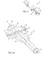
- FIG. 1is a perspective view of a device for repairing a meniscal tear according to the present teachings
- FIG. 1Ais a perspective view of a distal end of the device of FIG. 1 ;
- FIG. 2is a perspective view of the device of FIG. 1 with a first button depressed
- FIG. 2Ais a perspective view of the distal end of the device of FIG. 1 with first and second wings illustrated in an extended position;
- FIG. 3is a perspective view of the device of FIG. 1 with a second button depressed;
- FIG. 3Ais a perspective view of the distal end of the device of FIG. 1 with first and second needles illustrated in an extended position;
- FIG. 4is a perspective view of the device of FIG. 4 with a third button depressed
- FIG. 4Ais a perspective view of the distal end of the device of FIG. 1 with the first and the second wings illustrated in a retracted position and the first and the second needles in the process of moving from the extended position to a retracted position;
- FIG. 5is a perspective view of the distal end of the device of FIG. 1 with the first and the second needles illustrated in a further retracted position to withdraw a suture from the device;
- FIG. 6is a top view of the device of FIG. 1 and a superior view of a meniscus having a tear to be sutured using the device;
- FIG. 7illustrates the device inserted through the tear of the meniscus with the first and the second wings in the extended position
- FIG. 8illustrates the device inserted through the tear of the meniscus with the first and the second needles in the extended position
- FIG. 9illustrates the device inserted through the tear of the meniscus with the wings and the needles in their respective retracted positions
- FIG. 10illustrates the device being withdrawn from the meniscus
- FIG. 11illustrates the meniscus with a suture through the tear, the suture implanted using the device
- FIG. 12illustrates the suture tensioned and knotted to secure the tear in a closed position
- FIG. 13is a top view of another device according to the present teachings and a superior view of a meniscus having a tear, the device is inserted through the tear in order to insert a suture through the tear;
- FIG. 14illustrates the device of FIG. 13 having a single wing and a single needle both in an extended position
- FIG. 15illustrates the suture inserted through the tear
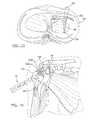
- FIG. 16illustrates use of the device of FIG. 1 to repair a torn rotator cuff
- FIG. 17illustrates use of the device of FIG. 1 to repair a separated rotator cuff.
- the device 10includes a main body 12 and an extended or elongated shaft portion 14 that extends from the main body 12 .
- the main body 12includes at least one button, switch, or any other device suitable for operating the device 10 . As illustrated, the main body 12 includes a first button 16 , a second button 18 , and a third button 20 .
- the device 10can include any suitable number of buttons for operating or activating the device 10 .
- the extended shaft portion 14includes a proximal end 22 and a distal end 24 .
- the proximal end 22is mounted to the main body 12 .
- the distal end 24is opposite to the proximal end 22 .
- the distal end 24includes a pointed conical tip 26 , a first retractable wing 28 , a second retractable wing 30 , a first needle 32 , and a second needle 34 .
- the pointed conical tip 26is designed to pierce tissue, such as soft tissue, muscle, and bone.
- the pointed conical tip 26can be sharpened to facilitate piercing the tissue.
- the pointed conical tip 26includes or defines a pair of openings 36 connected by a slot 37 .
- the openings 36can be located at any suitable location on the tip 26 .
- the slot 37extends between the openings 36 across a distal portion of the tip 26 .
- the first and the second retractable wings 28 and 30are positioned at opposite sides of the distal end 24 .
- the first and the second wings 28 and 30can take the form of any device suitable for supporting a suture.
- each of the first wing 28 and the second wing 30include a suture guide 40 and a needle opening 42 .
- the suture guides 40can take the form of any suitable device for guiding a suture from the extended shaft portion 14 around the wings 28 and 30 and to the tip 26 .
- the suture guides 40can take the form of recesses, indentations, or c-channels formed in the wings 28 and 30 .
- the needle openings 42are openings in each of the first wing 28 and the second wing 30 that extend completely through each of the first and second wings 28 and 30 and are each sized to receive one of the needles 32 and 34 .
- Each wing 28 and 30is movable between a retracted position ( FIG. 1A ) in which the wings 28 and 30 do not extend from the distal end 24 and an extended position ( FIG. 2A ) in which the wings 28 and 30 do extend from the distal end 24 .
- the wings 28 and 30are movable to the extended position by actuating the first button 16 ( FIG. 2 ) and are movable to the retracted position by actuating the third button 20 ( FIG. 4 ), as further described herein.
- the first and second needles 32 and 34can be any suitable device capable of penetrating biological matter, such as meniscal tissue, and capturing and/or retaining a suture.
- the first and second needles 32 and 34can each include a retention surface or notch 44 and 46 respectively.
- the retention surfaces 44 and 46can be any suitable surface or device for retaining and/or capturing a suture.
- the retention surfaces 44 and 46can be hooks or notches formed within each of the first needle 32 and the second needle 34 respectively.
- the first and second needles 32 and 34are positioned at opposite sides of the distal end 24 .
- a position of the first needle 32corresponds to a position of the first wing 28 .
- a position of the second needle 34corresponds to a position of the second wing 30 .
- the first and the second needles 32 and 34are movable between a retracted position ( FIGS. 1A and 2A ) and an extended position ( FIG. 3A ). In the retracted position, the first and second needles 32 and 34 do not protrude from the extended shaft portion 14 . In the extended position, the first needle 32 extends through the needle opening 42 of the first wing 28 and the second needle 34 extends through the needle opening 42 of the second wing 30 . The first and second needles 32 and 34 are prealigned with the needle openings 42 so that when the needles 32 and 34 are moved to the extended position the needles 32 and 34 extend through the openings 42 .
- the first and second needles 32 and 34can be moved from the retracted position to the extended position by pressing the second button 18 ( FIG. 3 ).
- the needles 32 and 34return to the retracted position after reaching the extended position, as illustrated in FIG. 4A .
- the needles 32 and 34are returned to the retracted position using any suitable device, such as a spring mechanism.
- the distal end 24is configured to receive any suitable fastening device for use in repairing a menicsal tear.
- the fastening deviceis illustrated as a suture 48 .
- the suture 48is mounted to the distal end 24 such that a first end 50 of the suture 48 is mounted to, or proximate to, the first wing 28 and a second end 52 is mounted to, or proximate to, the second wing 30 .
- the suture 48extends along the first wing 28 within the suture guide 40 to the tip 26 , where the suture 48 passes through the opening 36 and into the distal end 24 .
- the suture 48extends within the distal end 24 and then returns back to the tip 26 at a loop 54 .
- the suture 48extends back through the opening 36 to the second wing 30 .
- the suture 48extends around the second wing 30 to the distal end 24 along the suture guide 40 of the second wing 30 and is secured at the distal end 24 .
- the first button 16can be depressed ( FIG. 2 ) to move the first wing 28 and the second wing 30 into the extended position of FIG. 2A .
- the second button 18can be depressed ( FIG. 3 ) to move the first and the second needles 32 and 34 to the extended position in which the needles 32 and 34 extend through the openings 42 in the first and the second wings 28 and 30 .
- the first and the second needles 32 and 34revert to the retracted position.
- the suture 48is captured by the retention surfaces 44 and 46 and the first and the second wings 28 and 30 can be moved back to the retracted position by pressing the third button 20 , as illustrated in FIGS. 4 and 4A .
- the first and the second needles 32 and 34they pull the suture 48 such that the loop 54 extends out from within the distal end 24 , as illustrated in FIG. 5 .
- the suture 48is attached to the distal end 24 of the device 10 and the distal end 24 is inserted through the meniscus 80 and through the tear 82 .
- the tissue piercing pointed tip 26facilitates insertion of the device 10 through the meniscus 80 .
- the first button 16is pressed to move the first and the second wings 28 and 30 to the extended position.
- the first and the second needles 32 and 34are moved to the extended position by pressing the second button 18 .
- the deviceis positioned such that as the first and the second needles 32 and 34 move to the extended position they form two holes in the meniscus 80 through the tear 82 , which is in addition to a hole created by the tip 26 of the device 10 .
- the first and the second needles 32 and 34automatically return to the retracted position from the extended position and the first and the second wings 28 and 30 return to the retracted position by pressing the third button 20 .
- the first and the second needles 32 and 34retract, they engage the suture 48 by way of the retention surfaces 44 and 46 and pull the suture 48 through the tear 82 by way of the holes created by the needles.
- Withdrawing the device 10 from within the tear 82 and the meniscus 80further pulls the suture 48 through the tear 82 and causes the loop 54 of the suture to be withdrawn from within the distal end 24 .
- tensionis applied to the first end 50 and the second end 52 of the suture 48 to close the tear 82 .
- the suture 48can be tied into a knot to secure the suture 48 in place.
- the hole remaining in the meniscus 80 created by the tip 26can be used for a variety of different purposes. For example, the hole can receive a meniscal conduit for directing a variety of different biologics, such as nutrients, to the meniscus 80 .
- the device 110includes a main body 112 and an extended or elongated shaft portion 114 that extends from the main body 112 .
- the main body 112includes at least one button, switch, or any other device suitable for operating the device 110 .
- the device 110includes a first button 116 , a second button 118 , and a third button 120 .
- the device 110can include any suitable number of buttons for operating the device 110 .
- the extended shaft portion 114includes a proximal end 122 and a distal end 124 .
- the proximal end 122is mounted to the main body 112 .
- the distal end 124is opposite to the proximal end 122 .
- the distal end 124includes a pointed conical tip 126 , a single suture support illustrated as a single retractable wing 128 , and a single suture capturing device illustrated as a single needle 130 .
- the pointed conical tip 126is designed to pierce tissue.
- the pointed conical tip 126includes or defines an opening 132 .
- the opening 132can be located at any suitable location on the tip 126 .
- the retractable wing 128can include a suture guide and a needle opening.
- the suture guidecan take the form of any suitable device for guiding a suture from the extended shaft portion 114 around the wing 128 and to the tip 126 .
- the suture guidecan take the form of a recess, indentation, or c-channel formed in the wing 128 , such as the recess 40 of FIG. 2A .
- the needle openingis an opening in the wing 128 that extends completely through the wing 128 and is sized to receive the needle 130 .
- the wing 128is movable between a retracted position in which the wing 128 does not extend from the distal end 124 and an extended position ( FIG. 13 ) in which the wing 128 does extend from the distal end 124 .
- the wing 128is movable to the extended position by actuating the first button 116 .
- the wing 128is movable to the retracted position by actuating the third button 120 .
- the needle 130can be any device capable of penetrating biological matter, such as meniscal tissue.
- the needle 130includes a retention surface.
- the retention surfacecan be any suitable surface or device for retaining and/or capturing a suture.
- the retention surfacecan be a hook or notch formed within the needle 130 , such as is illustrated at reference number 44 of FIG. 3A .
- the needle 130is positioned at a side portion of the distal end 124 .
- the needle 130is aligned with the wing 128 .
- the needle 130is movable between a retracted position ( FIG. 13 ) and an extended shaft position ( FIG. 14 ). In the retracted position, the needle 130 does not protrude from the extended shaft portion 114 . In the extended position, the needle 130 protrudes from the extended shaft portion 114 and extends through the needle opening of the wing 128 .
- the needle 130can be moved from the retracted position to the extended position by pressing the second button 118 .
- the needle 130automatically returns to the retracted position after reaching the extended position.
- the distal end 124can receive any suitable fastening device for use in various surgical procedures, such as repairing a meniscal tear.
- the fastening deviceis illustrated as a suture 134 .
- the suture 134is mounted to the distal end 124 such that a first end 136 of the suture 134 is mounted to, or proximate to, the wing 128 and a second end 138 extends through the opening 132 of the tip 126 and is mounted within the distal end 124 .
- FIGS. 13-15illustrate use of the device 110 to repair a meniscus 150 having a tear 152 .
- the device 110is inserted through the meniscus 150 and the tear 152 , as illustrated in FIG. 13 , such that the distal end 124 , and the wing 128 in particular, pass entirely through the meniscus 150 .
- the pointed tip 126permits the device 110 to pierce the tough meniscus 150 .
- the device 110is inserted through the meniscus 150 with the wing 128 in the retracted position.
- the first button 116is pressed to move the wing 128 to the extended position, as illustrated in FIG. 13 .
- the second button 118is pressed to move the needle 130 to the extended position, as illustrated in FIG. 14 .
- the needle 130extends through the tear 152 to create a hole in the tear 152 .
- the device 110creates only two holes through the tear 152 , the first hole is created by the pointed tip 126 and the second hole is created by the needle 130 .
- the needle 130After reaching the extended position, the needle 130 returns to the retracted position. As the needle 130 returns to the retracted position, the retention surface of the needle 130 captures the suture 134 and pulls the suture 134 back through the meniscus 150 and the tear 152 . After the needle 130 captures the suture 134 , the wing 128 is retracted by pressing the third button 120 . As the device 110 is withdrawn back through the tear and out of the meniscus 150 , the first end 136 of the suture is pulled through the hole formed by the needle 130 and the second end 138 of the suture 134 is pulled through the hole formed by the tip 126 , as illustrated in FIG. 15 . The suture 134 can then be tensioned and secured, such as by throwing a knot, to close the tear 152 .
- the device 10can also be used to close and repair a tear 154 in a rotator cuff 156 .
- the device 10can be used to repair most any type of rotator cuff tear, including a margin convergence tear and the tears described in United States Publication No. 2006/0029633 filed on Aug. 3, 2004 and assigned to Biomet Sports Medicine, LLC of Warsaw, Ind., which is incorporated herein by reference.
- the above described method for repairing tear 82can also be used to repair the tear 154 in the rotator cuff 156 using a suture 158 .
- the device 10pierces the rotator cuff 156 with the tip 26 such that the device 10 is transverse to the tear 154 and extends through both a first side of the tear 154 a and a second side of the tear 154 b .
- the device 110can also be used to repair the rotator cuff 156 .
- the device 10can also be used to repair a rotator cuff 160 that has separated from a humerus bone 162 .
- Most any type of rotator cuff separationcan be repaired using the device 10 , such as the separations described in U.S. Pat. No. 6,514,274 filed on Feb. 4, 2003 and assigned to Biomet Sports Medicine, LLC of Warsaw, Ind., which is incorporated herein by reference.
- the device 10can be inserted through a bone hole 164 in the humerus 162 to pierce the rotator cuff 160 using the pointed tip 26 of the device 10 .
- the bone hole 164can be formed using any suitable device, including the device 10 .
- the tip 26is a bone piercing tip that can be driven through the humerus bone 162 .
- the device 10After the device 10 has pierced the rotator cuff 160 , it can be used to insert a suture 166 through the rotator cuff 160 in the same manner described above for inserting the suture 48 through the meniscus 80 , as illustrated in FIG. 11 . Therefore, the above method for threading the suture 48 through the meniscus 80 can also be used to thread suture 166 through rotator cuff 160 .
- the suture 166can be secured to the humerus bone 162 using in any suitable manner, such as with a bone plate 168 .
- the device 10can be inserted in the opposite direction whereby it pierces the rotator cuff 160 prior to extending through the humerus bone 162 . Further, the device 110 can also be used to repair the rotator cuff 160 .
Landscapes
- Health & Medical Sciences (AREA)
- Life Sciences & Earth Sciences (AREA)
- Surgery (AREA)
- Heart & Thoracic Surgery (AREA)
- Engineering & Computer Science (AREA)
- Biomedical Technology (AREA)
- Nuclear Medicine, Radiotherapy & Molecular Imaging (AREA)
- Medical Informatics (AREA)
- Molecular Biology (AREA)
- Animal Behavior & Ethology (AREA)
- General Health & Medical Sciences (AREA)
- Public Health (AREA)
- Veterinary Medicine (AREA)
- Surgical Instruments (AREA)
Abstract
Description
Claims (13)
Priority Applications (2)
| Application Number | Priority Date | Filing Date | Title |
|---|---|---|---|
| US12/437,605US8241305B2 (en) | 2008-05-08 | 2009-05-08 | Method for repairing a meniscal tear |
| US13/551,453US8491609B2 (en) | 2008-05-08 | 2012-07-17 | Device for repairing a meniscal tear |
Applications Claiming Priority (2)
| Application Number | Priority Date | Filing Date | Title |
|---|---|---|---|
| US5152008P | 2008-05-08 | 2008-05-08 | |
| US12/437,605US8241305B2 (en) | 2008-05-08 | 2009-05-08 | Method for repairing a meniscal tear |
Related Child Applications (1)
| Application Number | Title | Priority Date | Filing Date |
|---|---|---|---|
| US13/551,453DivisionUS8491609B2 (en) | 2008-05-08 | 2012-07-17 | Device for repairing a meniscal tear |
Publications (2)
| Publication Number | Publication Date |
|---|---|
| US20090281555A1 US20090281555A1 (en) | 2009-11-12 |
| US8241305B2true US8241305B2 (en) | 2012-08-14 |
Family
ID=41267463
Family Applications (2)
| Application Number | Title | Priority Date | Filing Date |
|---|---|---|---|
| US12/437,605Active2030-06-18US8241305B2 (en) | 2008-05-08 | 2009-05-08 | Method for repairing a meniscal tear |
| US13/551,453Expired - Fee RelatedUS8491609B2 (en) | 2008-05-08 | 2012-07-17 | Device for repairing a meniscal tear |
Family Applications After (1)
| Application Number | Title | Priority Date | Filing Date |
|---|---|---|---|
| US13/551,453Expired - Fee RelatedUS8491609B2 (en) | 2008-05-08 | 2012-07-17 | Device for repairing a meniscal tear |
Country Status (1)
| Country | Link |
|---|---|
| US (2) | US8241305B2 (en) |
Cited By (20)
| Publication number | Priority date | Publication date | Assignee | Title |
|---|---|---|---|---|
| US20120296373A1 (en)* | 2011-05-19 | 2012-11-22 | Abbott Cardiovascular Systems, Inc. | Closure devices and methods |
| US8795334B2 (en) | 2011-01-28 | 2014-08-05 | Smith & Nephew, Inc. | Tissue repair |
| US8821494B2 (en) | 2012-08-03 | 2014-09-02 | Howmedica Osteonics Corp. | Surgical instruments and methods of use |
| US8986327B2 (en) | 2012-10-18 | 2015-03-24 | Smith & Nephew, Inc. | Flexible anchor delivery system |
| US9084597B2 (en) | 2012-03-09 | 2015-07-21 | Smith & Nephew, Inc. | Suture-based knotless repair |
| US9402620B2 (en) | 2013-03-04 | 2016-08-02 | Howmedica Osteonics Corp. | Knotless filamentary fixation devices, assemblies and systems and methods of assembly and use |
| US9445803B2 (en) | 2011-11-23 | 2016-09-20 | Howmedica Osteonics Corp. | Filamentary suture anchor |
| US9463013B2 (en) | 2013-03-13 | 2016-10-11 | Stryker Corporation | Adjustable continuous filament structure and method of manufacture and use |
| US9788826B2 (en) | 2013-03-11 | 2017-10-17 | Howmedica Osteonics Corp. | Filamentary fixation device and assembly and method of assembly, manufacture and use |
| US9949732B2 (en) | 2005-02-07 | 2018-04-24 | Ivy Sports Medicine, Llc | System and method for all-inside suture fixation for implant attachment and soft tissue repair |
| US9986992B2 (en) | 2014-10-28 | 2018-06-05 | Stryker Corporation | Suture anchor and associated methods of use |
| US10231744B2 (en) | 2009-08-20 | 2019-03-19 | Howmedica Osteonics Corp. | Flexible ACL instrumentation, kit and method |
| US10548590B2 (en) | 2005-02-07 | 2020-02-04 | Ivy Sports Medicine, Llc | System and method for all-inside suture fixation for implant attachment and soft tissue repair |
| US10568616B2 (en) | 2014-12-17 | 2020-02-25 | Howmedica Osteonics Corp. | Instruments and methods of soft tissue fixation |
| US10610211B2 (en) | 2013-12-12 | 2020-04-07 | Howmedica Osteonics Corp. | Filament engagement system and methods of use |
| US10653409B2 (en) | 2015-12-04 | 2020-05-19 | Crossroads Extremity Systems, Llc | Devices and methods for anchoring tissue |
| USD902405S1 (en) | 2018-02-22 | 2020-11-17 | Stryker Corporation | Self-punching bone anchor inserter |
| US10932769B2 (en) | 2016-05-26 | 2021-03-02 | Ivy Sports Medicine, Llc | System and method for all-inside suture fixation for implant attachment and soft tissue repair |
| US11331094B2 (en) | 2013-04-22 | 2022-05-17 | Stryker Corporation | Method and apparatus for attaching tissue to bone |
| US11457912B2 (en) | 2016-06-02 | 2022-10-04 | Parcus Medical, Llc | Suture tool and method of use |
Families Citing this family (44)
| Publication number | Priority date | Publication date | Assignee | Title |
|---|---|---|---|---|
| US7842048B2 (en) | 2006-08-18 | 2010-11-30 | Abbott Laboratories | Articulating suture device and method |
| US8137364B2 (en)* | 2003-09-11 | 2012-03-20 | Abbott Laboratories | Articulating suturing device and method |
| US8758400B2 (en) | 2000-01-05 | 2014-06-24 | Integrated Vascular Systems, Inc. | Closure system and methods of use |
| DE60144328D1 (en) | 2000-09-08 | 2011-05-12 | Abbott Vascular Inc | Surgical clamp |
| US6695867B2 (en) | 2002-02-21 | 2004-02-24 | Integrated Vascular Systems, Inc. | Plunger apparatus and methods for delivering a closure device |
| US8690910B2 (en) | 2000-12-07 | 2014-04-08 | Integrated Vascular Systems, Inc. | Closure device and methods for making and using them |
| IES20030424A2 (en) | 2002-06-04 | 2003-12-10 | Robert Stevenson | Blood vessel closure clip and delivery device |
| US7160309B2 (en) | 2002-12-31 | 2007-01-09 | Laveille Kao Voss | Systems for anchoring a medical device in a body lumen |
| US8202293B2 (en) | 2003-01-30 | 2012-06-19 | Integrated Vascular Systems, Inc. | Clip applier and methods of use |
| US8398656B2 (en) | 2003-01-30 | 2013-03-19 | Integrated Vascular Systems, Inc. | Clip applier and methods of use |
| US7462188B2 (en) | 2003-09-26 | 2008-12-09 | Abbott Laboratories | Device and method for suturing intracardiac defects |
| US7449024B2 (en) | 2003-12-23 | 2008-11-11 | Abbott Laboratories | Suturing device with split arm and method of suturing tissue |
| US8313497B2 (en) | 2005-07-01 | 2012-11-20 | Abbott Laboratories | Clip applier and methods of use |
| US8267947B2 (en) | 2005-08-08 | 2012-09-18 | Abbott Laboratories | Vascular suturing device |
| US8556930B2 (en) | 2006-06-28 | 2013-10-15 | Abbott Laboratories | Vessel closure device |
| US8574244B2 (en)* | 2007-06-25 | 2013-11-05 | Abbott Laboratories | System for closing a puncture in a vessel wall |
| CA2702952C (en) | 2007-10-27 | 2017-01-03 | Parcus Medical, Llc | Suture anchor |
| US9282965B2 (en) | 2008-05-16 | 2016-03-15 | Abbott Laboratories | Apparatus and methods for engaging tissue |
| US9486191B2 (en) | 2009-01-09 | 2016-11-08 | Abbott Vascular, Inc. | Closure devices |
| US20130310853A1 (en)* | 2009-01-09 | 2013-11-21 | Abbott Cardiovascular Systems Inc. | Method and apparatus for percutaneous treatment of a blood vessel |
| JP5720031B2 (en) | 2009-01-12 | 2015-05-20 | テレフレックス メディカル インコーポレイテッドTeleflex Medical Incorporated | Apparatus and method for tissue closure |
| US20100185234A1 (en) | 2009-01-16 | 2010-07-22 | Abbott Vascular Inc. | Closure devices, systems, and methods |
| US20110054492A1 (en) | 2009-08-26 | 2011-03-03 | Abbott Laboratories | Medical device for repairing a fistula |
| US9370353B2 (en) | 2010-09-01 | 2016-06-21 | Abbott Cardiovascular Systems, Inc. | Suturing devices and methods |
| US8663252B2 (en)* | 2010-09-01 | 2014-03-04 | Abbott Cardiovascular Systems, Inc. | Suturing devices and methods |
| CA2860645C (en) | 2012-01-04 | 2019-11-05 | Teleflex Medical Incorporated | Apparatus and methods for tissue closure |
| FR2987737B1 (en)* | 2012-03-09 | 2014-04-18 | Arnold Ferlin | SYSTEM FOR REALIZING ANASTOMOSIS BETWEEN A WALL AND A CONDUIT |
| US8864778B2 (en) | 2012-04-10 | 2014-10-21 | Abbott Cardiovascular Systems, Inc. | Apparatus and method for suturing body lumens |
| US8858573B2 (en) | 2012-04-10 | 2014-10-14 | Abbott Cardiovascular Systems, Inc. | Apparatus and method for suturing body lumens |
| US9241707B2 (en) | 2012-05-31 | 2016-01-26 | Abbott Cardiovascular Systems, Inc. | Systems, methods, and devices for closing holes in body lumens |
| JP5963559B2 (en) | 2012-06-18 | 2016-08-03 | 日本コヴィディエン株式会社 | Medical suture tool |
| US9364209B2 (en) | 2012-12-21 | 2016-06-14 | Abbott Cardiovascular Systems, Inc. | Articulating suturing device |
| US9510823B2 (en) | 2013-08-02 | 2016-12-06 | Covidien Lp | Devices, systems, and methods for wound closure |
| WO2015171962A1 (en) | 2014-05-07 | 2015-11-12 | Bart Bracy | Multipart suture |
| KR101591056B1 (en)* | 2014-11-21 | 2016-02-18 | 김기성 | sewing cotton for laparoscopic port site closure device |
| US10219803B2 (en) | 2016-03-01 | 2019-03-05 | Ryan Grant | Surgical instrument |
| US11517301B2 (en) | 2016-06-02 | 2022-12-06 | Parcus Medical, Llc | Surgical tool and method of use |
| US10426449B2 (en) | 2017-02-16 | 2019-10-01 | Abbott Cardiovascular Systems, Inc. | Articulating suturing device with improved actuation and alignment mechanisms |
| CN108652711B (en)* | 2017-04-01 | 2021-08-06 | 江苏风和医疗器材股份有限公司 | Puncture core assembly with sewing function and puncture device thereof |
| CN109199481B (en)* | 2017-07-03 | 2021-01-05 | 江苏风和医疗器材股份有限公司 | Suturing assembly for suturing puncture hole |
| CN109199546B (en)* | 2017-07-03 | 2020-11-10 | 江苏风和医疗器材股份有限公司 | Puncture core assembly with sewing function and puncture device thereof |
| US11213288B2 (en) | 2018-05-02 | 2022-01-04 | Covidien Lp | Port site closure instrument |
| CN114668437B (en)* | 2022-05-31 | 2022-08-26 | 杭州锐健马斯汀医疗器材有限公司 | Suturing device |
| US20240115257A1 (en)* | 2022-10-11 | 2024-04-11 | Robert Lee Bromley | Integrated Closure Device |
Citations (8)
| Publication number | Priority date | Publication date | Assignee | Title |
|---|---|---|---|---|
| US6117144A (en) | 1995-08-24 | 2000-09-12 | Sutura, Inc. | Suturing device and method for sealing an opening in a blood vessel or other biological structure |
| US6514274B1 (en) | 2000-02-25 | 2003-02-04 | Arthrotek, Inc. | Method and apparatus for rotator cuff repair |
| US6562052B2 (en)* | 1995-08-24 | 2003-05-13 | Sutura, Inc. | Suturing device and method |
| US6733509B2 (en) | 2000-08-25 | 2004-05-11 | Sutura, Inc. | Suture cutter |
| US6911034B2 (en)* | 2000-06-14 | 2005-06-28 | Sterilis, Inc. | Suturing method and apparatus |
| US20060029633A1 (en) | 2004-08-03 | 2006-02-09 | Arthrotek, Inc | Biological patch for use in medical procedures |
| US20080269786A1 (en)* | 2007-03-29 | 2008-10-30 | Nobles Anthony A | Suturing Devices and Methods for Closing a Patent Foramen Ovale |
| US7918868B2 (en)* | 2006-05-22 | 2011-04-05 | Scandius Biomendical, Inc. | Method and apparatus for meniscal repair |
Family Cites Families (1)
| Publication number | Priority date | Publication date | Assignee | Title |
|---|---|---|---|---|
| US5817112A (en)* | 1997-09-22 | 1998-10-06 | Surgical Inventions & Innovations, Inc | Christoudias fascial closure device |
- 2009
- 2009-05-08USUS12/437,605patent/US8241305B2/enactiveActive
- 2012
- 2012-07-17USUS13/551,453patent/US8491609B2/ennot_activeExpired - Fee Related
Patent Citations (12)
| Publication number | Priority date | Publication date | Assignee | Title |
|---|---|---|---|---|
| US6117144A (en) | 1995-08-24 | 2000-09-12 | Sutura, Inc. | Suturing device and method for sealing an opening in a blood vessel or other biological structure |
| US6245079B1 (en) | 1995-08-24 | 2001-06-12 | Sutura, Inc. | Suturing device and method for sealing an opening in a blood vessel or other biological structure |
| US6551331B2 (en) | 1995-08-24 | 2003-04-22 | Sutura, Inc. | Suturing device and method for sealing an opening in a blood vessel or other biological structure |
| US6562052B2 (en)* | 1995-08-24 | 2003-05-13 | Sutura, Inc. | Suturing device and method |
| US7004952B2 (en) | 1995-08-24 | 2006-02-28 | Sutura, Inc. | Suturing device and method for sealing an opening in a blood vessel for other biological structure |
| US7090686B2 (en) | 1995-08-24 | 2006-08-15 | Sutura, Inc. | Suturing device and method |
| US6514274B1 (en) | 2000-02-25 | 2003-02-04 | Arthrotek, Inc. | Method and apparatus for rotator cuff repair |
| US6911034B2 (en)* | 2000-06-14 | 2005-06-28 | Sterilis, Inc. | Suturing method and apparatus |
| US6733509B2 (en) | 2000-08-25 | 2004-05-11 | Sutura, Inc. | Suture cutter |
| US20060029633A1 (en) | 2004-08-03 | 2006-02-09 | Arthrotek, Inc | Biological patch for use in medical procedures |
| US7918868B2 (en)* | 2006-05-22 | 2011-04-05 | Scandius Biomendical, Inc. | Method and apparatus for meniscal repair |
| US20080269786A1 (en)* | 2007-03-29 | 2008-10-30 | Nobles Anthony A | Suturing Devices and Methods for Closing a Patent Foramen Ovale |
Cited By (49)
| Publication number | Priority date | Publication date | Assignee | Title |
|---|---|---|---|---|
| US9949732B2 (en) | 2005-02-07 | 2018-04-24 | Ivy Sports Medicine, Llc | System and method for all-inside suture fixation for implant attachment and soft tissue repair |
| US10548590B2 (en) | 2005-02-07 | 2020-02-04 | Ivy Sports Medicine, Llc | System and method for all-inside suture fixation for implant attachment and soft tissue repair |
| US10231744B2 (en) | 2009-08-20 | 2019-03-19 | Howmedica Osteonics Corp. | Flexible ACL instrumentation, kit and method |
| US12419655B2 (en) | 2009-08-20 | 2025-09-23 | Howmedica Osteonics Corp. | Flexible ACL instrumentation, kit and method |
| US11364041B2 (en) | 2009-08-20 | 2022-06-21 | Howmedica Osteonics Corp. | Flexible ACL instrumentation, kit and method |
| US9078651B2 (en) | 2011-01-28 | 2015-07-14 | Smith & Nephew, Inc. | Tissue repair |
| US10631844B2 (en) | 2011-01-28 | 2020-04-28 | Smith & Nephew, Inc. | Tissue repair |
| US9370352B2 (en) | 2011-01-28 | 2016-06-21 | Smith & Nephew, Inc. | Tissue repair |
| US11857176B2 (en) | 2011-01-28 | 2024-01-02 | Smith & Nephew, Inc. | Tissue repair |
| US8795334B2 (en) | 2011-01-28 | 2014-08-05 | Smith & Nephew, Inc. | Tissue repair |
| US9332981B2 (en)* | 2011-05-19 | 2016-05-10 | Abbott Cardiovascular Systems, Inc. | Closure devices and methods |
| US11051801B2 (en) | 2011-05-19 | 2021-07-06 | Abbott Cardiovascular Systems, Inc. | Closure devices and methods |
| US12178427B2 (en) | 2011-05-19 | 2024-12-31 | Abbott Cardiovascular Systems, Inc. | Closure devices and methods |
| US10271834B2 (en) | 2011-05-19 | 2019-04-30 | Abbott Cardiovascular Systems, Inc. | Closure devices and methods |
| US20120296373A1 (en)* | 2011-05-19 | 2012-11-22 | Abbott Cardiovascular Systems, Inc. | Closure devices and methods |
| US11759199B2 (en) | 2011-05-19 | 2023-09-19 | Abbott Cardiovascular Systems, Inc. | Closure devices and methods |
| US9445803B2 (en) | 2011-11-23 | 2016-09-20 | Howmedica Osteonics Corp. | Filamentary suture anchor |
| US10448944B2 (en) | 2011-11-23 | 2019-10-22 | Howmedica Osteonics Corp. | Filamentary fixation device |
| US11844508B2 (en) | 2011-11-23 | 2023-12-19 | Howmedica Osteonics Corp. | Filamentary fixation device |
| US9820731B2 (en) | 2012-03-09 | 2017-11-21 | Smith & Nephew, Inc. | Suture-based knotless repair |
| US9084597B2 (en) | 2012-03-09 | 2015-07-21 | Smith & Nephew, Inc. | Suture-based knotless repair |
| US10653410B2 (en) | 2012-08-03 | 2020-05-19 | Howmedica Osteonics Corp. | Soft tissue fixation devices and methods |
| US9226744B2 (en) | 2012-08-03 | 2016-01-05 | Howmedica Osteonics Corp. | Surgical instruments and methods of use |
| US10123792B2 (en) | 2012-08-03 | 2018-11-13 | Howmedica Osteonics Corp. | Soft tissue fixation devices and methods |
| US8821494B2 (en) | 2012-08-03 | 2014-09-02 | Howmedica Osteonics Corp. | Surgical instruments and methods of use |
| US12171422B2 (en) | 2012-08-03 | 2024-12-24 | Howmedica Osteonics Corp. | Soft tissue fixation device and methods |
| US10010314B2 (en) | 2012-10-18 | 2018-07-03 | Smith & Nephew, Inc. | Flexible anchor delivery system |
| US10010316B2 (en) | 2012-10-18 | 2018-07-03 | Smith & Nephew, Inc. | Flexible anchor delivery system |
| US8986327B2 (en) | 2012-10-18 | 2015-03-24 | Smith & Nephew, Inc. | Flexible anchor delivery system |
| US12096929B2 (en) | 2012-10-18 | 2024-09-24 | Smith & Nephew, Inc. | Flexible anchor delivery system |
| US9402620B2 (en) | 2013-03-04 | 2016-08-02 | Howmedica Osteonics Corp. | Knotless filamentary fixation devices, assemblies and systems and methods of assembly and use |
| US10285685B2 (en) | 2013-03-04 | 2019-05-14 | Howmedica Osteonics Corp. | Knotless filamentary fixation devices, assemblies and systems and methods of assembly and use |
| US9788826B2 (en) | 2013-03-11 | 2017-10-17 | Howmedica Osteonics Corp. | Filamentary fixation device and assembly and method of assembly, manufacture and use |
| US9463013B2 (en) | 2013-03-13 | 2016-10-11 | Stryker Corporation | Adjustable continuous filament structure and method of manufacture and use |
| US11331094B2 (en) | 2013-04-22 | 2022-05-17 | Stryker Corporation | Method and apparatus for attaching tissue to bone |
| US12048427B2 (en) | 2013-04-22 | 2024-07-30 | Stryker Corporation | Method and apparatus for attaching tissue to bone |
| US10610211B2 (en) | 2013-12-12 | 2020-04-07 | Howmedica Osteonics Corp. | Filament engagement system and methods of use |
| US11006945B2 (en) | 2014-10-28 | 2021-05-18 | Stryker Corporation | Suture anchor and associated methods of use |
| US9986992B2 (en) | 2014-10-28 | 2018-06-05 | Stryker Corporation | Suture anchor and associated methods of use |
| US10568616B2 (en) | 2014-12-17 | 2020-02-25 | Howmedica Osteonics Corp. | Instruments and methods of soft tissue fixation |
| US11806005B2 (en) | 2015-12-04 | 2023-11-07 | Crossroads Extremity Systems, Llc | Devices and methods for anchoring tissue |
| US10653409B2 (en) | 2015-12-04 | 2020-05-19 | Crossroads Extremity Systems, Llc | Devices and methods for anchoring tissue |
| US11696752B2 (en) | 2016-05-26 | 2023-07-11 | Stryker Corporation | Systems and methods for all-inside suture fixation for implant attachment and soft tissue repair |
| US10932769B2 (en) | 2016-05-26 | 2021-03-02 | Ivy Sports Medicine, Llc | System and method for all-inside suture fixation for implant attachment and soft tissue repair |
| US11457912B2 (en) | 2016-06-02 | 2022-10-04 | Parcus Medical, Llc | Suture tool and method of use |
| US12274436B2 (en) | 2016-06-02 | 2025-04-15 | Parcus Medical, Llc | Suture tool and method of use |
| USD976405S1 (en) | 2018-02-22 | 2023-01-24 | Stryker Corporation | Self-punching bone anchor inserter |
| USD958989S1 (en) | 2018-02-22 | 2022-07-26 | Stryker Corporation | Self-punching bone anchor inserter |
| USD902405S1 (en) | 2018-02-22 | 2020-11-17 | Stryker Corporation | Self-punching bone anchor inserter |
Also Published As
| Publication number | Publication date |
|---|---|
| US20090281555A1 (en) | 2009-11-12 |
| US8491609B2 (en) | 2013-07-23 |
| US20130012962A1 (en) | 2013-01-10 |
Similar Documents
| Publication | Publication Date | Title |
|---|---|---|
| US8241305B2 (en) | Method for repairing a meniscal tear | |
| US11612391B2 (en) | Soft tissue repair device and associated methods | |
| US11617572B2 (en) | Soft tissue repair device and associated methods | |
| US10667803B2 (en) | Systems and methods for repairing tissue | |
| US11103232B2 (en) | Knotless suture, and kit containing same | |
| US10485532B2 (en) | Suture passer device including a blunt tip and a sharp tip | |
| US20150327849A1 (en) | Suture anchor eyelet with suture loader | |
| US20060241694A1 (en) | Suture fixation device and method for surgical repair | |
| US20140222034A1 (en) | Suture passers | |
| US10603028B2 (en) | Finger traps for collapsible suture loops | |
| EP4349277A2 (en) | Device for tissue repair | |
| US20240081810A1 (en) | Soft tissue repair device and associated methods | |
| CN108601649B (en) | Joint stabilizing device |
Legal Events
| Date | Code | Title | Description |
|---|---|---|---|
| AS | Assignment | Owner name:BIOMET SPORTS MEDICINE, LLC, INDIANA Free format text:ASSIGNMENT OF ASSIGNORS INTEREST;ASSIGNOR:STONE, KEVIN T.;REEL/FRAME:022655/0954 Effective date:20090507 | |
| AS | Assignment | Owner name:BANK OF AMERICA, N.A., AS ADMINISTRATIVE AGENT FOR Free format text:SECURITY AGREEMENT;ASSIGNORS:LVB ACQUISITION, INC.;BIOMET, INC.;BIOMET 3I, LLC;AND OTHERS;REEL/FRAME:023505/0241 Effective date:20091111 | |
| STCF | Information on status: patent grant | Free format text:PATENTED CASE | |
| CC | Certificate of correction | ||
| AS | Assignment | Owner name:BIOMET EUROPE LTD., INDIANA Free format text:RELEASE OF SECURITY INTEREST IN PATENTS RECORDED AT REEL 023505/ FRAME 0241;ASSIGNOR:BANK OF AMERICA, N.A., AS ADMINISTRATIVE AGENT;REEL/FRAME:037155/0082 Effective date:20150624 Owner name:BIOMET 3I, LLC, FLORIDA Free format text:RELEASE OF SECURITY INTEREST IN PATENTS RECORDED AT REEL 023505/ FRAME 0241;ASSIGNOR:BANK OF AMERICA, N.A., AS ADMINISTRATIVE AGENT;REEL/FRAME:037155/0082 Effective date:20150624 Owner name:BIOMET FAIR LAWN LLC, NEW JERSEY Free format text:RELEASE OF SECURITY INTEREST IN PATENTS RECORDED AT REEL 023505/ FRAME 0241;ASSIGNOR:BANK OF AMERICA, N.A., AS ADMINISTRATIVE AGENT;REEL/FRAME:037155/0082 Effective date:20150624 Owner name:BIOMET TRAVEL, INC., INDIANA Free format text:RELEASE OF SECURITY INTEREST IN PATENTS RECORDED AT REEL 023505/ FRAME 0241;ASSIGNOR:BANK OF AMERICA, N.A., AS ADMINISTRATIVE AGENT;REEL/FRAME:037155/0082 Effective date:20150624 Owner name:EBI, LLC, INDIANA Free format text:RELEASE OF SECURITY INTEREST IN PATENTS RECORDED AT REEL 023505/ FRAME 0241;ASSIGNOR:BANK OF AMERICA, N.A., AS ADMINISTRATIVE AGENT;REEL/FRAME:037155/0082 Effective date:20150624 Owner name:BIOMET HOLDINGS LTD., INDIANA Free format text:RELEASE OF SECURITY INTEREST IN PATENTS RECORDED AT REEL 023505/ FRAME 0241;ASSIGNOR:BANK OF AMERICA, N.A., AS ADMINISTRATIVE AGENT;REEL/FRAME:037155/0082 Effective date:20150624 Owner name:BIOMET INTERNATIONAL LTD., INDIANA Free format text:RELEASE OF SECURITY INTEREST IN PATENTS RECORDED AT REEL 023505/ FRAME 0241;ASSIGNOR:BANK OF AMERICA, N.A., AS ADMINISTRATIVE AGENT;REEL/FRAME:037155/0082 Effective date:20150624 Owner name:LVB ACQUISITION, INC., INDIANA Free format text:RELEASE OF SECURITY INTEREST IN PATENTS RECORDED AT REEL 023505/ FRAME 0241;ASSIGNOR:BANK OF AMERICA, N.A., AS ADMINISTRATIVE AGENT;REEL/FRAME:037155/0082 Effective date:20150624 Owner name:BIOMET, INC., INDIANA Free format text:RELEASE OF SECURITY INTEREST IN PATENTS RECORDED AT REEL 023505/ FRAME 0241;ASSIGNOR:BANK OF AMERICA, N.A., AS ADMINISTRATIVE AGENT;REEL/FRAME:037155/0082 Effective date:20150624 Owner name:BIOMET ORTHOPEDICS, LLC, INDIANA Free format text:RELEASE OF SECURITY INTEREST IN PATENTS RECORDED AT REEL 023505/ FRAME 0241;ASSIGNOR:BANK OF AMERICA, N.A., AS ADMINISTRATIVE AGENT;REEL/FRAME:037155/0082 Effective date:20150624 Owner name:BIOLECTRON, INC., INDIANA Free format text:RELEASE OF SECURITY INTEREST IN PATENTS RECORDED AT REEL 023505/ FRAME 0241;ASSIGNOR:BANK OF AMERICA, N.A., AS ADMINISTRATIVE AGENT;REEL/FRAME:037155/0082 Effective date:20150624 Owner name:CROSS MEDICAL PRODUCTS, LLC, CALIFORNIA Free format text:RELEASE OF SECURITY INTEREST IN PATENTS RECORDED AT REEL 023505/ FRAME 0241;ASSIGNOR:BANK OF AMERICA, N.A., AS ADMINISTRATIVE AGENT;REEL/FRAME:037155/0082 Effective date:20150624 Owner name:ELECTR-OBIOLOGY, LLC, INDIANA Free format text:RELEASE OF SECURITY INTEREST IN PATENTS RECORDED AT REEL 023505/ FRAME 0241;ASSIGNOR:BANK OF AMERICA, N.A., AS ADMINISTRATIVE AGENT;REEL/FRAME:037155/0082 Effective date:20150624 Owner name:EBI HOLDINGS, LLC, INDIANA Free format text:RELEASE OF SECURITY INTEREST IN PATENTS RECORDED AT REEL 023505/ FRAME 0241;ASSIGNOR:BANK OF AMERICA, N.A., AS ADMINISTRATIVE AGENT;REEL/FRAME:037155/0082 Effective date:20150624 Owner name:INTERPORE CROSS INTERNATIONAL, LLC, CALIFORNIA Free format text:RELEASE OF SECURITY INTEREST IN PATENTS RECORDED AT REEL 023505/ FRAME 0241;ASSIGNOR:BANK OF AMERICA, N.A., AS ADMINISTRATIVE AGENT;REEL/FRAME:037155/0082 Effective date:20150624 Owner name:INTERPORE SPINE, LTD., CALIFORNIA Free format text:RELEASE OF SECURITY INTEREST IN PATENTS RECORDED AT REEL 023505/ FRAME 0241;ASSIGNOR:BANK OF AMERICA, N.A., AS ADMINISTRATIVE AGENT;REEL/FRAME:037155/0082 Effective date:20150624 Owner name:IMPLANT INNOVATIONS HOLDINGS, LLC, INDIANA Free format text:RELEASE OF SECURITY INTEREST IN PATENTS RECORDED AT REEL 023505/ FRAME 0241;ASSIGNOR:BANK OF AMERICA, N.A., AS ADMINISTRATIVE AGENT;REEL/FRAME:037155/0082 Effective date:20150624 Owner name:BIOMET SPORTS MEDICINE, LLC, INDIANA Free format text:RELEASE OF SECURITY INTEREST IN PATENTS RECORDED AT REEL 023505/ FRAME 0241;ASSIGNOR:BANK OF AMERICA, N.A., AS ADMINISTRATIVE AGENT;REEL/FRAME:037155/0082 Effective date:20150624 Owner name:BIOMET LEASING, INC., INDIANA Free format text:RELEASE OF SECURITY INTEREST IN PATENTS RECORDED AT REEL 023505/ FRAME 0241;ASSIGNOR:BANK OF AMERICA, N.A., AS ADMINISTRATIVE AGENT;REEL/FRAME:037155/0082 Effective date:20150624 Owner name:KIRSCHNER MEDICAL CORPORATION, INDIANA Free format text:RELEASE OF SECURITY INTEREST IN PATENTS RECORDED AT REEL 023505/ FRAME 0241;ASSIGNOR:BANK OF AMERICA, N.A., AS ADMINISTRATIVE AGENT;REEL/FRAME:037155/0082 Effective date:20150624 Owner name:BIOMET MANUFACTURING CORPORATION, INDIANA Free format text:RELEASE OF SECURITY INTEREST IN PATENTS RECORDED AT REEL 023505/ FRAME 0241;ASSIGNOR:BANK OF AMERICA, N.A., AS ADMINISTRATIVE AGENT;REEL/FRAME:037155/0082 Effective date:20150624 Owner name:EBI MEDICAL SYSTEMS, LLC, INDIANA Free format text:RELEASE OF SECURITY INTEREST IN PATENTS RECORDED AT REEL 023505/ FRAME 0241;ASSIGNOR:BANK OF AMERICA, N.A., AS ADMINISTRATIVE AGENT;REEL/FRAME:037155/0082 Effective date:20150624 Owner name:BIOMET BIOLOGICS, LLC., INDIANA Free format text:RELEASE OF SECURITY INTEREST IN PATENTS RECORDED AT REEL 023505/ FRAME 0241;ASSIGNOR:BANK OF AMERICA, N.A., AS ADMINISTRATIVE AGENT;REEL/FRAME:037155/0082 Effective date:20150624 Owner name:BIOMET FLORIDA SERVICES, LLC, INDIANA Free format text:RELEASE OF SECURITY INTEREST IN PATENTS RECORDED AT REEL 023505/ FRAME 0241;ASSIGNOR:BANK OF AMERICA, N.A., AS ADMINISTRATIVE AGENT;REEL/FRAME:037155/0082 Effective date:20150624 Owner name:BIOMET MICROFIXATION, LLC, FLORIDA Free format text:RELEASE OF SECURITY INTEREST IN PATENTS RECORDED AT REEL 023505/ FRAME 0241;ASSIGNOR:BANK OF AMERICA, N.A., AS ADMINISTRATIVE AGENT;REEL/FRAME:037155/0082 Effective date:20150624 | |
| FPAY | Fee payment | Year of fee payment:4 | |
| AS | Assignment | Owner name:BIOMET, INC., INDIANA Free format text:ASSIGNMENT OF ASSIGNORS INTEREST;ASSIGNOR:BIOMET U.S. RECONSTRUCTION, LLC;REEL/FRAME:045935/0557 Effective date:20171103 Owner name:BIOMET U.S. RECONSTRUCTION, LLC, INDIANA Free format text:ASSIGNMENT OF ASSIGNORS INTEREST;ASSIGNOR:BIOMET SPORTS MEDICINE, LLC;REEL/FRAME:045935/0497 Effective date:20171103 Owner name:ZB MANUFACTURING, LLC, INDIANA Free format text:ASSIGNMENT OF ASSIGNORS INTEREST;ASSIGNOR:BIOMET, INC.;REEL/FRAME:045935/0570 Effective date:20171103 Owner name:BIOMET MANUFACTURING, LLC, INDIANA Free format text:ASSIGNMENT OF ASSIGNORS INTEREST;ASSIGNOR:ZB MANUFACTURING, LLC;REEL/FRAME:045935/0673 Effective date:20171103 | |
| MAFP | Maintenance fee payment | Free format text:PAYMENT OF MAINTENANCE FEE, 8TH YEAR, LARGE ENTITY (ORIGINAL EVENT CODE: M1552); ENTITY STATUS OF PATENT OWNER: LARGE ENTITY Year of fee payment:8 | |
| MAFP | Maintenance fee payment | Free format text:PAYMENT OF MAINTENANCE FEE, 12TH YEAR, LARGE ENTITY (ORIGINAL EVENT CODE: M1553); ENTITY STATUS OF PATENT OWNER: LARGE ENTITY Year of fee payment:12 |