US8241138B2 - Apparatuses, methods and systems for improving sports playing abilities - Google Patents
Apparatuses, methods and systems for improving sports playing abilitiesDownload PDFInfo
- Publication number
- US8241138B2 US8241138B2US12/692,571US69257110AUS8241138B2US 8241138 B2US8241138 B2US 8241138B2US 69257110 AUS69257110 AUS 69257110AUS 8241138 B2US8241138 B2US 8241138B2
- Authority
- US
- United States
- Prior art keywords
- club
- vertical
- markings
- golfer
- grip
- Prior art date
- Legal status (The legal status is an assumption and is not a legal conclusion. Google has not performed a legal analysis and makes no representation as to the accuracy of the status listed.)
- Expired - Fee Related, expires
Links
- 238000000034methodMethods0.000titleabstractdescription7
- 230000007935neutral effectEffects0.000claimsdescription43
- 230000006872improvementEffects0.000abstractdescription4
- 238000012549trainingMethods0.000abstractdescription4
- 238000012544monitoring processMethods0.000abstractdescription3
- 230000000007visual effectEffects0.000description15
- XEEYBQQBJWHFJM-UHFFFAOYSA-NIronChemical compound[Fe]XEEYBQQBJWHFJM-UHFFFAOYSA-N0.000description4
- 230000001133accelerationEffects0.000description2
- 230000008859changeEffects0.000description2
- 229910052742ironInorganic materials0.000description2
- 235000000396ironNutrition0.000description2
- 238000004519manufacturing processMethods0.000description2
- 230000008569processEffects0.000description2
- OKTJSMMVPCPJKN-UHFFFAOYSA-NCarbonChemical compound[C]OKTJSMMVPCPJKN-UHFFFAOYSA-N0.000description1
- 229910000831SteelInorganic materials0.000description1
- 230000008901benefitEffects0.000description1
- 239000011248coating agentSubstances0.000description1
- 238000000576coating methodMethods0.000description1
- 238000004590computer programMethods0.000description1
- 238000011161developmentMethods0.000description1
- 239000003292glueSubstances0.000description1
- 229910002804graphiteInorganic materials0.000description1
- 239000010439graphiteSubstances0.000description1
- 229910001092metal group alloyInorganic materials0.000description1
- 238000011160researchMethods0.000description1
- 230000001953sensory effectEffects0.000description1
- 239000010959steelSubstances0.000description1
- 239000002023woodSubstances0.000description1
Images


Classifications
- A—HUMAN NECESSITIES
- A63—SPORTS; GAMES; AMUSEMENTS
- A63B—APPARATUS FOR PHYSICAL TRAINING, GYMNASTICS, SWIMMING, CLIMBING, OR FENCING; BALL GAMES; TRAINING EQUIPMENT
- A63B69/00—Training appliances or apparatus for special sports
- A63B69/36—Training appliances or apparatus for special sports for golf
- A63B69/3617—Striking surfaces with impact indicating means, e.g. markers
- A—HUMAN NECESSITIES
- A63—SPORTS; GAMES; AMUSEMENTS
- A63B—APPARATUS FOR PHYSICAL TRAINING, GYMNASTICS, SWIMMING, CLIMBING, OR FENCING; BALL GAMES; TRAINING EQUIPMENT
- A63B69/00—Training appliances or apparatus for special sports
- A63B69/36—Training appliances or apparatus for special sports for golf
- A63B69/3623—Training appliances or apparatus for special sports for golf for driving
- A63B69/3632—Clubs or attachments on clubs, e.g. for measuring, aligning
- A—HUMAN NECESSITIES
- A63—SPORTS; GAMES; AMUSEMENTS
- A63B—APPARATUS FOR PHYSICAL TRAINING, GYMNASTICS, SWIMMING, CLIMBING, OR FENCING; BALL GAMES; TRAINING EQUIPMENT
- A63B71/00—Games or sports accessories not covered in groups A63B1/00 - A63B69/00
- A63B71/06—Indicating or scoring devices for games or players, or for other sports activities
- A63B71/0619—Displays, user interfaces and indicating devices, specially adapted for sport equipment, e.g. display mounted on treadmills
- A63B71/0622—Visual, audio or audio-visual systems for entertaining, instructing or motivating the user
- A63B2071/0625—Emitting sound, noise or music
- A—HUMAN NECESSITIES
- A63—SPORTS; GAMES; AMUSEMENTS
- A63B—APPARATUS FOR PHYSICAL TRAINING, GYMNASTICS, SWIMMING, CLIMBING, OR FENCING; BALL GAMES; TRAINING EQUIPMENT
- A63B71/00—Games or sports accessories not covered in groups A63B1/00 - A63B69/00
- A63B71/06—Indicating or scoring devices for games or players, or for other sports activities
- A63B71/0619—Displays, user interfaces and indicating devices, specially adapted for sport equipment, e.g. display mounted on treadmills
- A63B71/0622—Visual, audio or audio-visual systems for entertaining, instructing or motivating the user
- A63B2071/0638—Displaying moving images of recorded environment, e.g. virtual environment
- A—HUMAN NECESSITIES
- A63—SPORTS; GAMES; AMUSEMENTS
- A63B—APPARATUS FOR PHYSICAL TRAINING, GYMNASTICS, SWIMMING, CLIMBING, OR FENCING; BALL GAMES; TRAINING EQUIPMENT
- A63B71/00—Games or sports accessories not covered in groups A63B1/00 - A63B69/00
- A63B71/06—Indicating or scoring devices for games or players, or for other sports activities
- A63B71/0619—Displays, user interfaces and indicating devices, specially adapted for sport equipment, e.g. display mounted on treadmills
- A63B2071/0655—Tactile feedback
- A—HUMAN NECESSITIES
- A63—SPORTS; GAMES; AMUSEMENTS
- A63B—APPARATUS FOR PHYSICAL TRAINING, GYMNASTICS, SWIMMING, CLIMBING, OR FENCING; BALL GAMES; TRAINING EQUIPMENT
- A63B71/00—Games or sports accessories not covered in groups A63B1/00 - A63B69/00
- A63B71/06—Indicating or scoring devices for games or players, or for other sports activities
- A63B2071/0694—Visual indication, e.g. Indicia
- A—HUMAN NECESSITIES
- A63—SPORTS; GAMES; AMUSEMENTS
- A63B—APPARATUS FOR PHYSICAL TRAINING, GYMNASTICS, SWIMMING, CLIMBING, OR FENCING; BALL GAMES; TRAINING EQUIPMENT
- A63B2220/00—Measuring of physical parameters relating to sporting activity
- A63B2220/10—Positions
- A63B2220/16—Angular positions
- A—HUMAN NECESSITIES
- A63—SPORTS; GAMES; AMUSEMENTS
- A63B—APPARATUS FOR PHYSICAL TRAINING, GYMNASTICS, SWIMMING, CLIMBING, OR FENCING; BALL GAMES; TRAINING EQUIPMENT
- A63B2220/00—Measuring of physical parameters relating to sporting activity
- A63B2220/20—Distances or displacements
- A—HUMAN NECESSITIES
- A63—SPORTS; GAMES; AMUSEMENTS
- A63B—APPARATUS FOR PHYSICAL TRAINING, GYMNASTICS, SWIMMING, CLIMBING, OR FENCING; BALL GAMES; TRAINING EQUIPMENT
- A63B2220/00—Measuring of physical parameters relating to sporting activity
- A63B2220/40—Acceleration
- A—HUMAN NECESSITIES
- A63—SPORTS; GAMES; AMUSEMENTS
- A63B—APPARATUS FOR PHYSICAL TRAINING, GYMNASTICS, SWIMMING, CLIMBING, OR FENCING; BALL GAMES; TRAINING EQUIPMENT
- A63B2220/00—Measuring of physical parameters relating to sporting activity
- A63B2220/80—Special sensors, transducers or devices therefor
- A63B2220/805—Optical or opto-electronic sensors
- A—HUMAN NECESSITIES
- A63—SPORTS; GAMES; AMUSEMENTS
- A63B—APPARATUS FOR PHYSICAL TRAINING, GYMNASTICS, SWIMMING, CLIMBING, OR FENCING; BALL GAMES; TRAINING EQUIPMENT
- A63B2220/00—Measuring of physical parameters relating to sporting activity
- A63B2220/80—Special sensors, transducers or devices therefor
- A63B2220/83—Special sensors, transducers or devices therefor characterised by the position of the sensor
- A63B2220/833—Sensors arranged on the exercise apparatus or sports implement
- A—HUMAN NECESSITIES
- A63—SPORTS; GAMES; AMUSEMENTS
- A63B—APPARATUS FOR PHYSICAL TRAINING, GYMNASTICS, SWIMMING, CLIMBING, OR FENCING; BALL GAMES; TRAINING EQUIPMENT
- A63B2225/00—Miscellaneous features of sport apparatus, devices or equipment
- A63B2225/50—Wireless data transmission, e.g. by radio transmitters or telemetry
- A—HUMAN NECESSITIES
- A63—SPORTS; GAMES; AMUSEMENTS
- A63B—APPARATUS FOR PHYSICAL TRAINING, GYMNASTICS, SWIMMING, CLIMBING, OR FENCING; BALL GAMES; TRAINING EQUIPMENT
- A63B2225/00—Miscellaneous features of sport apparatus, devices or equipment
- A63B2225/74—Miscellaneous features of sport apparatus, devices or equipment with powered illuminating means, e.g. lights
- A—HUMAN NECESSITIES
- A63—SPORTS; GAMES; AMUSEMENTS
- A63B—APPARATUS FOR PHYSICAL TRAINING, GYMNASTICS, SWIMMING, CLIMBING, OR FENCING; BALL GAMES; TRAINING EQUIPMENT
- A63B71/00—Games or sports accessories not covered in groups A63B1/00 - A63B69/00
- A63B71/06—Indicating or scoring devices for games or players, or for other sports activities
- A63B71/0619—Displays, user interfaces and indicating devices, specially adapted for sport equipment, e.g. display mounted on treadmills
- A63B71/0622—Visual, audio or audio-visual systems for entertaining, instructing or motivating the user
- A—HUMAN NECESSITIES
- A63—SPORTS; GAMES; AMUSEMENTS
- A63F—CARD, BOARD, OR ROULETTE GAMES; INDOOR GAMES USING SMALL MOVING PLAYING BODIES; VIDEO GAMES; GAMES NOT OTHERWISE PROVIDED FOR
- A63F2300/00—Features of games using an electronically generated display having two or more dimensions, e.g. on a television screen, showing representations related to the game
- A63F2300/10—Features of games using an electronically generated display having two or more dimensions, e.g. on a television screen, showing representations related to the game characterized by input arrangements for converting player-generated signals into game device control signals
- A63F2300/1062—Features of games using an electronically generated display having two or more dimensions, e.g. on a television screen, showing representations related to the game characterized by input arrangements for converting player-generated signals into game device control signals being specially adapted to a type of game, e.g. steering wheel
- A—HUMAN NECESSITIES
- A63—SPORTS; GAMES; AMUSEMENTS
- A63F—CARD, BOARD, OR ROULETTE GAMES; INDOOR GAMES USING SMALL MOVING PLAYING BODIES; VIDEO GAMES; GAMES NOT OTHERWISE PROVIDED FOR
- A63F2300/00—Features of games using an electronically generated display having two or more dimensions, e.g. on a television screen, showing representations related to the game
- A63F2300/80—Features of games using an electronically generated display having two or more dimensions, e.g. on a television screen, showing representations related to the game specially adapted for executing a specific type of game
- A63F2300/8011—Ball
Definitions
- Embodiments of the claimed subject matterinclude sports training apparatuses which include a golf club made up of a head, a shaft and a grip wherein one or more markings are positioned on said head, shaft or grip or any combination of the head, ferrule, shaft and grip so said one or more markings may be used for monitoring and aiding in improvement of the player's performance.
- Other embodiments of the golf clubhave a ferrule which also may have one or more markings positioned on its exterior so that they can be used for monitoring and aiding in the improvement of the player's performance.
- embodimentsinclude the above described apparatus with the markings positioned at one or more locations about the external surface of one or more portions of the golf club. These portions include the head, the ferrule, the hosel, the shaft, and the grip. In yet other embodiments, two or more sets of markings are positioned on at least two different of the above described portions of the golf club. Other embodiments include the above described apparatus with the markings positioned at two or more of the described locations about the external surface of two or more portions or sections of the golf club. In several of these embodiments, the markings are positioned about the periphery of the one or more portions at least 10 degrees apart from one another. The markings may also be placed less or more than 10 degrees apart from each other depending on the desires of the user.
- Embodiments of the claimed subject matterrelate to sports equipment which can be used to help a user improve his or her skill level, and more particularly several embodiments relate to golf clubs such as golf irons, woods and hybrid style clubs.
- golf club manufacturershave used a variety of different manufacturing processes to manufacture golf clubs, some of which may be kept as trade secrets. Regardless of the process used, irons, woods and hybrid clubs have been typically designed in the same manner.
- Golfis played with a set of clubs with each club designed to launch the ball at a desired trajectory and distance.
- the variations available in trajectory and distanceare achieved with the use of a set of clubs with varying lengths and lofts and each club is uniquely identified by a numbering system and/or with a loft designation displayed on the club head. Golfers learn the approximate distance the ball will travel when hit by each club swung in a normal manner. The golfer can then select an appropriate club to execute a particular shot so the ball travels over a desired distance and trajectory so it has a greater chance of reaching its target. Varying distances as well as various trajectories may be achieved with individual clubs and each club can be used to hit the ball with additional adjustments for distance and trajectory through the manipulation of the loft and the length of the club.
- a “club head” also known as a “golf club head”has several elements.
- a typical club headincludes a sole/bottom, a face which is the hitting surface, a crown (the top in wood clubs), and a top line (iron clubs).
- Formed into the heel of the club headis a hosel which receives the shaft.
- the hoselis positioned within the heel with no markings or indicators.
- the userpositions the golf club by visually aligning the face to the desired target in an attempt to create the intended face angle specified by the manufacturer.
- Club manufacturersendeavor to change face angles by producing a variety of club heads, with each head employing a specific angle that is used to strike the ball.
- FIG. 1is a top view of a club head and hosel of an embodiment of the claimed subject matter
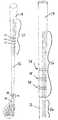
- FIG. 2is a elevational perspective view of a golf club of an embodiment of the claimed subject matter
- FIG. 3is a side view of a golf grip and portion of a shaft of an embodiment of the claimed subject matter
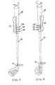
- FIG. 4is a perspective view of the club head and hosel rotated at a first angle according to an embodiment of the claimed subject matter
- FIG. 5is a perspective view of the club head and hosel rotated at a second angle according to an embodiment of the claimed subject matter
- FIG. 6is an exploded perspective view of the club head and hosel rotated at a first angle according to an embodiment of the claimed subject matter.
- FIG. 7is an exploded perspective view of the club head and hosel rotated at a second angle according to an embodiment of the claimed subject matter.
- Embodiments of the claimed subject matteruse visual indicators with existing sporting devices such as clubs and sticks.
- visual indicators or markingsmay be used by the user/player to aid in the adjustment of the face angle of the club head.
- the face angle position of the golf club faceis the angle relative to the intended line of ball flight. This angle can vary for different players.
- Other embodimentssimilarly use markings to aid in the adjustment of the striking face, such as the striking face of a stick used in the sport of hockey or as the catching face of a stick in the sport of lacrosse.
- Using the visual markings or indicators on a golf cluba golf player can minimize his or her problems of visually adjusting the face angle.
- Other userssuch as golf instructors can also use the visual markings to gauge whether or not the player is properly using the golf club.
- visual markings or indicatorsmay also be used to offer more than one club head face angle.
- One aspect of the embodimentsis to provide a golf club training system, method and apparatus which include a set of markings on one or more of the components of the club including the head, shaft, grip and ferrule so that the set of markings can aid the player and/or the player's coach in estimating the characteristics of the flight of the ball being impacted, for instance the estimated trajectory and distance for any given golf shot.
- FIG. 1discloses a club head 10 , also commonly referred to as an iron, having a striking surface denoted by a set of grooves 12 positioned in parallel configuration across the front facing surface of the head 10 and a hosel 14 .
- the hosel 14 of the club headprovides an attachment for a club shaft 16 which is partially shown protruding from and extending outward from the hosel 14 and extending through the ferrule 20 .
- the distal end of the shaft 16extends to at least the grip 18 of the club as illustrated in FIG. 2 .
- FIG. 2also illustrates an embodiment with the assembled club shaft 16 with a golf grip 18 at its distal end.
- a ferrule 20is shown positioned on the golf club just above the hosel 14 .
- a ferruleis typically a plastic or metal alloy sleeve that adorns the bottom of many steel and graphite golf club shafts just above the club head hosel. Ferrules can be used to dampen vibration and/or for aesthetic purposes.
- the golf grip 18overlays the distal or outward end of the club shaft 16 and the grip 18 is attached thereto by a fastener such as glue type of fastener.
- the grip 18may be attached using any known fastening process suitable to one skilled in the art and the grip 18 may be removable with a fastener which would allow the grip 18 to be applied and reapplied by a user.
- FIGS. 1 and 2also illustrate embodiments having markings 24 positioned in a vertical orientation on the ferrule 20 and markings 28 positioned in a horizontal orientation on both portions of grip 18 and portions of the upper/distal end of shaft 16 . These markings 24 and 28 are used in the embodiments as visual indicators for the player or another person to calibrate and/or estimate the position of the golf club before it is used to swing and hit or impact the ball.
- the markings 24 and 26are illustrated as positioned in parallel in a vertical orientation in relation to the longitudinal axis of the club shaft 16 and the markings 28 are illustrated as positioned in a horizontal orientation.
- the markings 24 , 26 and 28are also shown spaced apart from each other in equal spacing amounts.
- Other embodimentsmay have additional markings or markings in different configurations such as single dots and the space between the individual markings may also be varied.
- markings 26may be different on portions of the grip 18 and portions of the distal end of shaft 16 as illustrated in FIG. 3 .
- one or more of the markingscan be applied to the grip, shaft, hosel and/or ferrule of an existing club rather than being integrated into a newly manufactured golf clubs.
- the one or more markingscan also be applied in other manners such as with an external application device so that the grip is imprinted or branded with the markings.
- any number of suitable markingsmay be externally applied to one or more positions on the golf club using any fashion known to those skilled in the art.
- a sticker having markings 24may be affixed to the external surface of the grip 18 and/or the upper end of shaft 16 and another sticker may be used to affix the markings to the outer surface of the hosel 14 .
- a user or instructorcan apply one or more removable markings with a coating or sticker.
- FIG. 3illustrates the golf grip 18 and upper portion of the shaft 16 which is connected to the grip 18 along with a plurality of vertical markings 26 and horizontal markings 28 .
- the line markings shown in the figureact as visual or tactile indicators on the grip, and are positioned parallel to the longitudinal axis of the grip, and corresponding to the visual indicators inscribed on the shaft, ferrule and hosel, such that when the grip and club shaft are rotated about the longitudinal axis of the club shaft as shown in FIGS. 4 and 5 , the visual indicator markings on the hosel 14 and the lines positioned on the grip 18 are in alignment when in use.
- a first markinge.g. a visual or tactile marking line positioned on the golf grip 18
- the bottom surface of the club headlies perpendicular to the intended line of flight, therefore providing maximum distance of flight when the golf ball is impacted or struck.
- the first markingmay not be directly in view of the played when the player is in the neutral position.
- Other variations and embodimentsmay also be used as desired by the player or a third party such as the instructor or designer/manufacturer.
- Auditory feedbackmay also be used to reference various alignment positions, for example if the shaft were rotated in one position and then rotated to another position a noise could be emitted from a noise emitter located within the club components. Any suitable electronic or non electronic noise emitter responding to the one or more positions of the shaft alignment known to those skilled in the art may be used.
- markings 28positioned circumferentially about the grip portion of the club. These markings 28 may be placed at pre-selected locations along the axis of the grip for calibrating additional distances of the golf shot. In these embodiments illustrated in FIGS. 2-5 , the markings 28 positioned on the grip 18 can be used to position the players hands on the grip 18 so that the effective length of the club which is to be swung is changed according to the needs of the player. These embodiments allow the user to maintain the club head so it may be used in a predictable manner while at the same time allowing for an offering of several face angles and that aid in the player's improved performance by allowing the user to deliver the club head to an impact position which is based on the player's needs.
- the markings 24are used by rotating the golf shaft about its longitudinal axis in prescribed amounts of rotation.
- the rotation of the shaftcauses the club head to correspondingly rotate to selected degrees (a and b) from the longitudinal axis of the club shaft. This results in a situation known as laying the club face open. Golf shots made with the club laid open are typically higher and shorter. Since the markings or visual indicators inscribed in the hosel, ferrule and/or shaft are in alignment with the markings (visual or tactile) lines formed on the grip, and when the golf club is held in reference to the lines on the grip, the distance of travel of the golf ball can easily be calibrated and repeated.
- the markingsare positioned at one or more pre-selected locations along the length and/or axis of the grip. These markings can be used for adjusting the user's golf shot, for instance when the markings are used with an existing golf club or when they are manufactured into a golf club's body, such as the golf club's grip. Other embodiments include one or more markings and/or inscriptions positioned circumferentially about the grip portion of the club.
- Other embodimentsinclude clubs with markings such as raised tactile inscriptions such as bumps or grooves may also be used or they may be used in conjunction with visual markings.
- the markings used for estimating the character of the resulting hit or catchcan be vertical, horizontal or of any suitable shape and size.
- the markingsmay be inscribed into the outer surface of the grip or any other portion of the club or stick which can be viewed by the user or by another user such as an instructor observing the player.
- Other areas of the clubinclude interior portions of the club which can be viewed through the grip such markings positioned under a clear plastic grip.
- Several of the embodimentsinclude the use of a sticker having markings suitably positioned and spaced around the periphery of the club's grip.
- a range of face angle positionsare possible by placing the markings on either a single component, the head, shaft, ferrule and grip, all, and/or a combination of these components so that the player/user of the golf club or any other person observing the player, such as an instructor, can use the markings to estimate the change in position of the golf club in the player's hands.
- the changes made to the position of the golf clubwould enable the player to make allowances for making changes to the distance and/or the flight characteristics of the golf ball being impacted.
- the characteristics of the flight of the ballinclude the vertical angle of the flight from the ground, the estimated highest flight level of the golf ball and the horizontal angle of the ball's flight.
- the various golf head face angles facilitated by the markingscan deliver differing impact positions to the golf ball and these varying positions can be based on the individual player type's needs or the changes made by others such as a golf instructor in order to aid in the improvement of the player's performance.
- a club gripmay include one or more computer or electronic implemented haptic feedback functions such as those found in the DUALSHOCK controller manufactured by Sony Computer Entertainment, Inc. or the Wii Remote manufactured by Nintendo Co., Ltd.
- a haptic feedback componentis included into the grip.
- This componentis manufactured integrally into the grip so it is not visible to the player but at the same time can be controlled remotely with a remote interface element.
- the outputcould be a remote signal such as one sent through a radio frequency wave to a receiver such as a Bluetooth headset.
- the componentin several embodiments may also include a vibration component to signal the player when the golf club is positioned in a proper orientation, another predetermined orientation, a user preset orientation, or when the club is placed in one orientation versus another orientation.
- the golf clubhas the ability to sense acceleration along three axes through the use of an accelerometer such as the ADXL330 accelerometer used in the Wii Remote.
- an accelerometersuch as the ADXL330 accelerometer used in the Wii Remote.
- One or more additional sensorsmay also be used to determine the orientation of one or more components of the club.
- Another embodimentcould be used as a Wii Remote is used for use in a video game that is programmed to train the user to make swings in various directions and orientations. With these embodiments, a player could practice using a gaming console that uses video from previously recorded games as references.
- Other embodimentstrack the movement and orientation of the golf club in the field by recording the acceleration along three axes that is senses and playing it back alongside one or more videos of the golf swings and results. In this way, a player could effectively record the club's swing in three dimensions and match the results of the swing and impacts with the actual video results allowing the player to fine tune his or her playing style helping improve the player's ability in that sport, such as the sport of golf in this embodiment.
- Additional components that may be included with such a training deviceis a haptic display and other electronic implemented devices which can sense as well as record, if needed, the finger and hand pressure and placement on the grip.
- These componentsmay also record the sensory output from the components so that they may be played back with other sensor output signals alongside a recording of the actual golf shot so that the parameters used on the golf club as well as the position and movement of the golf club may be tracked to the results of the actual swing used in the field to impact the golf ball.
- markings or visual indicators on portions of the golf clubincluding markings on the hosel and corresponding markings on the grip may be visual or tactile and they may include electronic means such as vibration components. Lines in the grip may also be employed for closing the face of the club head such that predictable and repeatable distances may also be obtained.
Landscapes
- Health & Medical Sciences (AREA)
- General Health & Medical Sciences (AREA)
- Physical Education & Sports Medicine (AREA)
- Golf Clubs (AREA)
Abstract
Description
Claims (18)
Priority Applications (1)
| Application Number | Priority Date | Filing Date | Title |
|---|---|---|---|
| US12/692,571US8241138B2 (en) | 2009-04-09 | 2010-01-22 | Apparatuses, methods and systems for improving sports playing abilities |
Applications Claiming Priority (2)
| Application Number | Priority Date | Filing Date | Title |
|---|---|---|---|
| US21222009P | 2009-04-09 | 2009-04-09 | |
| US12/692,571US8241138B2 (en) | 2009-04-09 | 2010-01-22 | Apparatuses, methods and systems for improving sports playing abilities |
Publications (2)
| Publication Number | Publication Date |
|---|---|
| US20100261542A1 US20100261542A1 (en) | 2010-10-14 |
| US8241138B2true US8241138B2 (en) | 2012-08-14 |
Family
ID=42934835
Family Applications (1)
| Application Number | Title | Priority Date | Filing Date |
|---|---|---|---|
| US12/692,571Expired - Fee RelatedUS8241138B2 (en) | 2009-04-09 | 2010-01-22 | Apparatuses, methods and systems for improving sports playing abilities |
Country Status (1)
| Country | Link |
|---|---|
| US (1) | US8241138B2 (en) |
Cited By (10)
| Publication number | Priority date | Publication date | Assignee | Title |
|---|---|---|---|---|
| US20120252596A1 (en)* | 2010-01-27 | 2012-10-04 | Cameron Don T | Golf club with bezeled jewelry |
| US20130237341A1 (en)* | 2012-03-09 | 2013-09-12 | Thomas Bobby SMITH | Putting training device |
| US20140038742A1 (en)* | 2007-09-24 | 2014-02-06 | Lanny L. Johnson | Golf grip |
| US20150031469A1 (en)* | 2013-07-26 | 2015-01-29 | Dunlop Sports Co., Ltd. | Golf club |
| US9387379B1 (en)* | 2014-05-21 | 2016-07-12 | Brainstorm Golf, Inc. | Reversible golf club grip |
| US9962585B2 (en) | 2014-01-02 | 2018-05-08 | Arizona Board Of Regents On Behalf Of Arizona State University | Striking implement comprising a constrained frequency resonator |
| US10688364B2 (en)* | 2018-04-13 | 2020-06-23 | Bill Schmedes, III | Golf training aid and related method |
| US11331543B2 (en)* | 2020-05-04 | 2022-05-17 | ShortGameChef, LLC | Alignment aid for golf club |
| US11628347B2 (en)* | 2020-12-01 | 2023-04-18 | Lateral Line, Llc | Golf putter grip with integrated green reading and alignment system and golf putter incorporating same |
| USD1017744S1 (en) | 2021-04-29 | 2024-03-12 | ShortGameChef, LLC | Alignment aid for golf club |
Families Citing this family (5)
| Publication number | Priority date | Publication date | Assignee | Title |
|---|---|---|---|---|
| US8480511B2 (en)* | 2011-07-15 | 2013-07-09 | Taylor Made Golf Company, Inc. | Methods for marking golf club ferrule |
| US20150140533A1 (en)* | 2013-11-15 | 2015-05-21 | Benjamin NOVINSKI | Kit for instructing the proper use of sporting goods |
| US9821209B2 (en)* | 2014-12-26 | 2017-11-21 | Dunlop Sports Co. Ltd. | Golf swing analysis apparatus |
| US10518172B2 (en)* | 2016-03-07 | 2019-12-31 | Htc Corporation | Accessory management of virtual reality system |
| EP4271488A4 (en)* | 2020-12-30 | 2024-11-20 | Carroll, James, Howard | ALIGNMENT AID ON A GOLF GRIP OR GOLF SHAFT |
Citations (19)
| Publication number | Priority date | Publication date | Assignee | Title |
|---|---|---|---|---|
| US1126208A (en)* | 1914-10-19 | 1915-01-26 | Abner W Hayford | Golf-club. |
| US1433150A (en)* | 1922-02-11 | 1922-10-24 | Spalding & Bros Ag | Golf club |
| US1587082A (en)* | 1921-02-21 | 1926-06-01 | Crawford Mcgregor & Canby Co | Handle grip for golf clubs |
| US2446622A (en)* | 1946-08-30 | 1948-08-10 | Wilson Athletic Goods Mfg Co I | Method for producing grips for handles |
| US2865635A (en)* | 1956-08-07 | 1958-12-23 | Leslie A Jessen | Golf instruction device |
| US4222567A (en)* | 1978-10-10 | 1980-09-16 | The John Rouzee Green Co. | Golf club with loft angle markings |
| US4317568A (en)* | 1980-03-06 | 1982-03-02 | Green John R | Golf club with reference plumb mark |
| US4484746A (en)* | 1980-01-20 | 1984-11-27 | Brill Edward F | Golf putter |
| US4569525A (en)* | 1983-10-24 | 1986-02-11 | Folger James D | Golf club swing training device |
| US5228695A (en)* | 1992-07-30 | 1993-07-20 | Wilson Sporting Goods Co. | Golf club including alignment device |
| US5234217A (en)* | 1990-12-17 | 1993-08-10 | Outdoor Technologies Group | Golf clubs with integral alignment indicia |
| US5890977A (en)* | 1997-11-20 | 1999-04-06 | Taylor; John R. | Golf putter alignment method |
| US6648770B1 (en)* | 1999-06-10 | 2003-11-18 | John M. Snyder | Training golf iron |
| US6652388B1 (en)* | 2003-01-29 | 2003-11-25 | Callaway Golf Company | Method and apparatus for assembling a shaft to a golf club head and a golf club having such assembly |
| US20070123364A1 (en)* | 2005-11-30 | 2007-05-31 | Ray Solari | Method and device for coordinating golf swing and ball distance |
| US20090082120A1 (en)* | 2007-09-24 | 2009-03-26 | Johnson Lanny L | Visual and tactile confirmation golf grip and system |
| US20090270194A1 (en)* | 2005-10-25 | 2009-10-29 | Casati Jr Ettore | Golf Club Grip and Method of Using Same |
| US20100022323A1 (en)* | 2008-07-22 | 2010-01-28 | Nike, Inc. | Releasable and interchangeable connections for golf club heads and shafts |
| US20100041491A1 (en)* | 2008-08-18 | 2010-02-18 | Thomas James S | Orientation Marker for Golf Club Having Releasable and Interchangeable Head and Shaft Connections |
- 2010
- 2010-01-22USUS12/692,571patent/US8241138B2/ennot_activeExpired - Fee Related
Patent Citations (24)
| Publication number | Priority date | Publication date | Assignee | Title |
|---|---|---|---|---|
| US1126208A (en)* | 1914-10-19 | 1915-01-26 | Abner W Hayford | Golf-club. |
| US1587082A (en)* | 1921-02-21 | 1926-06-01 | Crawford Mcgregor & Canby Co | Handle grip for golf clubs |
| US1433150A (en)* | 1922-02-11 | 1922-10-24 | Spalding & Bros Ag | Golf club |
| US2446622A (en)* | 1946-08-30 | 1948-08-10 | Wilson Athletic Goods Mfg Co I | Method for producing grips for handles |
| US2865635A (en)* | 1956-08-07 | 1958-12-23 | Leslie A Jessen | Golf instruction device |
| US4222567A (en)* | 1978-10-10 | 1980-09-16 | The John Rouzee Green Co. | Golf club with loft angle markings |
| US4484746A (en)* | 1980-01-20 | 1984-11-27 | Brill Edward F | Golf putter |
| US4317568A (en)* | 1980-03-06 | 1982-03-02 | Green John R | Golf club with reference plumb mark |
| US4569525A (en)* | 1983-10-24 | 1986-02-11 | Folger James D | Golf club swing training device |
| US5234217A (en)* | 1990-12-17 | 1993-08-10 | Outdoor Technologies Group | Golf clubs with integral alignment indicia |
| US5228695A (en)* | 1992-07-30 | 1993-07-20 | Wilson Sporting Goods Co. | Golf club including alignment device |
| US5890977A (en)* | 1997-11-20 | 1999-04-06 | Taylor; John R. | Golf putter alignment method |
| US6648770B1 (en)* | 1999-06-10 | 2003-11-18 | John M. Snyder | Training golf iron |
| US6652388B1 (en)* | 2003-01-29 | 2003-11-25 | Callaway Golf Company | Method and apparatus for assembling a shaft to a golf club head and a golf club having such assembly |
| US7017252B2 (en)* | 2003-01-29 | 2006-03-28 | Konrad Lenhof | Method and apparatus for assembling a shaft to a golf club head |
| US20090270194A1 (en)* | 2005-10-25 | 2009-10-29 | Casati Jr Ettore | Golf Club Grip and Method of Using Same |
| US20070123364A1 (en)* | 2005-11-30 | 2007-05-31 | Ray Solari | Method and device for coordinating golf swing and ball distance |
| US20090082120A1 (en)* | 2007-09-24 | 2009-03-26 | Johnson Lanny L | Visual and tactile confirmation golf grip and system |
| US7637821B2 (en)* | 2007-09-24 | 2009-12-29 | Johnson Lanny L | Visual and tactile confirmation golf grip and system |
| US20100022323A1 (en)* | 2008-07-22 | 2010-01-28 | Nike, Inc. | Releasable and interchangeable connections for golf club heads and shafts |
| US7883430B2 (en)* | 2008-07-22 | 2011-02-08 | Nike, Inc. | Releasable and interchangeable connections for golf club heads and shafts |
| US8061008B2 (en)* | 2008-07-22 | 2011-11-22 | Nike, Inc. | Releasable and interchangeable connections for golf club heads and shafts |
| US20100041491A1 (en)* | 2008-08-18 | 2010-02-18 | Thomas James S | Orientation Marker for Golf Club Having Releasable and Interchangeable Head and Shaft Connections |
| US8075417B2 (en)* | 2008-08-18 | 2011-12-13 | Nike, Inc. | Orientation marker for golf club having releasable and interchangeable head and shaft connections |
Cited By (13)
| Publication number | Priority date | Publication date | Assignee | Title |
|---|---|---|---|---|
| US20140038742A1 (en)* | 2007-09-24 | 2014-02-06 | Lanny L. Johnson | Golf grip |
| US20120252596A1 (en)* | 2010-01-27 | 2012-10-04 | Cameron Don T | Golf club with bezeled jewelry |
| US10279228B2 (en)* | 2012-03-09 | 2019-05-07 | Thomas Bobby SMITH | Putting training device |
| US20130237341A1 (en)* | 2012-03-09 | 2013-09-12 | Thomas Bobby SMITH | Putting training device |
| US20150031469A1 (en)* | 2013-07-26 | 2015-01-29 | Dunlop Sports Co., Ltd. | Golf club |
| US9962585B2 (en) | 2014-01-02 | 2018-05-08 | Arizona Board Of Regents On Behalf Of Arizona State University | Striking implement comprising a constrained frequency resonator |
| US9387379B1 (en)* | 2014-05-21 | 2016-07-12 | Brainstorm Golf, Inc. | Reversible golf club grip |
| US10688364B2 (en)* | 2018-04-13 | 2020-06-23 | Bill Schmedes, III | Golf training aid and related method |
| US11135496B2 (en) | 2018-04-13 | 2021-10-05 | Bill Schmedes, III | Golf training aid and related method |
| US11331543B2 (en)* | 2020-05-04 | 2022-05-17 | ShortGameChef, LLC | Alignment aid for golf club |
| US11660510B2 (en) | 2020-05-04 | 2023-05-30 | ShortGameChef, LLC | Alignment aid for golf club |
| US11628347B2 (en)* | 2020-12-01 | 2023-04-18 | Lateral Line, Llc | Golf putter grip with integrated green reading and alignment system and golf putter incorporating same |
| USD1017744S1 (en) | 2021-04-29 | 2024-03-12 | ShortGameChef, LLC | Alignment aid for golf club |
Also Published As
| Publication number | Publication date |
|---|---|
| US20100261542A1 (en) | 2010-10-14 |
Similar Documents
| Publication | Publication Date | Title |
|---|---|---|
| US8241138B2 (en) | Apparatuses, methods and systems for improving sports playing abilities | |
| US10737165B2 (en) | Smart system for display of dynamic movement parameters in sport and training | |
| JP7206305B2 (en) | Two-environment gameplay system | |
| US6416327B1 (en) | Training device | |
| US8235830B2 (en) | Visual swing indicator golf club head | |
| US7614961B2 (en) | Golf putting teaching device and method | |
| US20020123386A1 (en) | Methods and systems for analyzing the motion of sporting equipment | |
| US20100130299A1 (en) | Visual Aid | |
| KR101907995B1 (en) | A Golf Simulator with a Function of Putting Guide and Control Method Thereof | |
| US20120252584A1 (en) | Accessory for a game console controller | |
| US7396288B2 (en) | Putting training device | |
| JP2017522978A (en) | Sports training apparatus and system | |
| US9174109B2 (en) | Golf club, training device and method for aligning hands with club face of golf club | |
| US20170326427A1 (en) | Golf swing teaching device | |
| US7104897B2 (en) | Golf swing training device | |
| KR101027652B1 (en) | Practice golf club | |
| US8012033B2 (en) | Golf swing trainer apparatus and method | |
| KR102586975B1 (en) | Golf grip guide pad and golf glove with thereof | |
| US20240058680A1 (en) | Golf training apparatus | |
| KR102004646B1 (en) | Pseudo golf club and virtual golf simulation device with multiple play modes using the same | |
| GB2457938A (en) | A training device for clubs or bats | |
| US20210093937A1 (en) | Smart system for display of dynamic movement parameters in sport and training | |
| Breed | The 3-degree putting solution: The comprehensive, scientifically proven guide to better putting | |
| US20080234064A1 (en) | Apparatus and method for teaching golf | |
| TW202106358A (en) | Club replacement method in golf virtual reality, and program product and system therefor allows the user to play the virtual golf exercise in a smaller space |
Legal Events
| Date | Code | Title | Description |
|---|---|---|---|
| AS | Assignment | Owner name:EHT GOLF CLUB DESIGN, CALIFORNIA Free format text:ASSIGNMENT OF ASSIGNORS INTEREST;ASSIGNORS:MCGINNIS, THOMAS;MAGLAGUE, PETER;REEL/FRAME:024133/0428 Effective date:20100323 | |
| AS | Assignment | Owner name:EHT GOLF DESIGN LLC, CALIFORNIA Free format text:ASSIGNMENT OF ASSIGNORS INTEREST;ASSIGNORS:MCGINNIS, THOMAS;MAGLAQUE, PETER;REEL/FRAME:024939/0494 Effective date:20100903 | |
| ZAAA | Notice of allowance and fees due | Free format text:ORIGINAL CODE: NOA | |
| ZAAB | Notice of allowance mailed | Free format text:ORIGINAL CODE: MN/=. | |
| STCF | Information on status: patent grant | Free format text:PATENTED CASE | |
| AS | Assignment | Owner name:EHT GOLF DESIGN LLC, CALIFORNIA Free format text:ASSIGNMENT OF ASSIGNORS INTEREST;ASSIGNORS:MCGINNIS, THOMAS;MAGLAQUE, PETER;REEL/FRAME:031447/0238 Effective date:20131003 | |
| FEPP | Fee payment procedure | Free format text:PATENT HOLDER CLAIMS MICRO ENTITY STATUS, ENTITY STATUS SET TO MICRO (ORIGINAL EVENT CODE: STOM); ENTITY STATUS OF PATENT OWNER: MICROENTITY | |
| FPAY | Fee payment | Year of fee payment:4 | |
| FEPP | Fee payment procedure | Free format text:MAINTENANCE FEE REMINDER MAILED (ORIGINAL EVENT CODE: REM.); ENTITY STATUS OF PATENT OWNER: MICROENTITY | |
| FEPP | Fee payment procedure | Free format text:SURCHARGE FOR LATE PAYMENT, MICRO ENTITY (ORIGINAL EVENT CODE: M3555); ENTITY STATUS OF PATENT OWNER: MICROENTITY | |
| MAFP | Maintenance fee payment | Free format text:PAYMENT OF MAINTENANCE FEE, 8TH YEAR, MICRO ENTITY (ORIGINAL EVENT CODE: M3552); ENTITY STATUS OF PATENT OWNER: MICROENTITY Year of fee payment:8 | |
| FEPP | Fee payment procedure | Free format text:MAINTENANCE FEE REMINDER MAILED (ORIGINAL EVENT CODE: REM.); ENTITY STATUS OF PATENT OWNER: MICROENTITY | |
| LAPS | Lapse for failure to pay maintenance fees | Free format text:PATENT EXPIRED FOR FAILURE TO PAY MAINTENANCE FEES (ORIGINAL EVENT CODE: EXP.); ENTITY STATUS OF PATENT OWNER: MICROENTITY | |
| STCH | Information on status: patent discontinuation | Free format text:PATENT EXPIRED DUE TO NONPAYMENT OF MAINTENANCE FEES UNDER 37 CFR 1.362 | |
| FP | Lapsed due to failure to pay maintenance fee | Effective date:20240814 |