US8240941B2 - Flexure with elongated openings - Google Patents
Flexure with elongated openingsDownload PDFInfo
- Publication number
- US8240941B2 US8240941B2US12/210,457US21045708AUS8240941B2US 8240941 B2US8240941 B2US 8240941B2US 21045708 AUS21045708 AUS 21045708AUS 8240941 B2US8240941 B2US 8240941B2
- Authority
- US
- United States
- Prior art keywords
- block
- neck
- flexure
- openings
- cylindrical
- Prior art date
- Legal status (The legal status is an assumption and is not a legal conclusion. Google has not performed a legal analysis and makes no representation as to the accuracy of the status listed.)
- Active, expires
Links
- 239000013013elastic materialSubstances0.000claimsdescription5
- 210000003739neckAnatomy0.000description31
- 239000000463materialSubstances0.000description3
- 238000000034methodMethods0.000description3
- 150000001875compoundsChemical class0.000description2
- 229910052751metalInorganic materials0.000description2
- 239000002184metalSubstances0.000description2
- 230000003287optical effectEffects0.000description2
- 2299100007556061-T6 aluminium alloyInorganic materials0.000description1
- 229910000831SteelInorganic materials0.000description1
- RTAQQCXQSZGOHL-UHFFFAOYSA-NTitaniumChemical compound[Ti]RTAQQCXQSZGOHL-UHFFFAOYSA-N0.000description1
- 229910052782aluminiumInorganic materials0.000description1
- XAGFODPZIPBFFR-UHFFFAOYSA-NaluminiumChemical compound[Al]XAGFODPZIPBFFR-UHFFFAOYSA-N0.000description1
- 238000005553drillingMethods0.000description1
- 238000003801millingMethods0.000description1
- 239000010959steelSubstances0.000description1
- 239000010936titaniumSubstances0.000description1
- 229910052719titaniumInorganic materials0.000description1
Images


Classifications
- F—MECHANICAL ENGINEERING; LIGHTING; HEATING; WEAPONS; BLASTING
- F16—ENGINEERING ELEMENTS AND UNITS; GENERAL MEASURES FOR PRODUCING AND MAINTAINING EFFECTIVE FUNCTIONING OF MACHINES OR INSTALLATIONS; THERMAL INSULATION IN GENERAL
- F16C—SHAFTS; FLEXIBLE SHAFTS; ELEMENTS OR CRANKSHAFT MECHANISMS; ROTARY BODIES OTHER THAN GEARING ELEMENTS; BEARINGS
- F16C11/00—Pivots; Pivotal connections
- F16C11/04—Pivotal connections
- F16C11/12—Pivotal connections incorporating flexible connections, e.g. leaf springs
- G—PHYSICS
- G02—OPTICS
- G02B—OPTICAL ELEMENTS, SYSTEMS OR APPARATUS
- G02B7/00—Mountings, adjusting means, or light-tight connections, for optical elements
- G02B7/003—Alignment of optical elements
- G—PHYSICS
- G02—OPTICS
- G02B—OPTICAL ELEMENTS, SYSTEMS OR APPARATUS
- G02B7/00—Mountings, adjusting means, or light-tight connections, for optical elements
- G02B7/18—Mountings, adjusting means, or light-tight connections, for optical elements for prisms; for mirrors
- G02B7/182—Mountings, adjusting means, or light-tight connections, for optical elements for prisms; for mirrors for mirrors
- G02B7/1821—Mountings, adjusting means, or light-tight connections, for optical elements for prisms; for mirrors for mirrors for rotating or oscillating mirrors
- G—PHYSICS
- G02—OPTICS
- G02B—OPTICAL ELEMENTS, SYSTEMS OR APPARATUS
- G02B7/00—Mountings, adjusting means, or light-tight connections, for optical elements
- G02B7/18—Mountings, adjusting means, or light-tight connections, for optical elements for prisms; for mirrors
- G02B7/182—Mountings, adjusting means, or light-tight connections, for optical elements for prisms; for mirrors for mirrors
- G02B7/1822—Mountings, adjusting means, or light-tight connections, for optical elements for prisms; for mirrors for mirrors comprising means for aligning the optical axis
- Y—GENERAL TAGGING OF NEW TECHNOLOGICAL DEVELOPMENTS; GENERAL TAGGING OF CROSS-SECTIONAL TECHNOLOGIES SPANNING OVER SEVERAL SECTIONS OF THE IPC; TECHNICAL SUBJECTS COVERED BY FORMER USPC CROSS-REFERENCE ART COLLECTIONS [XRACs] AND DIGESTS
- Y10—TECHNICAL SUBJECTS COVERED BY FORMER USPC
- Y10T—TECHNICAL SUBJECTS COVERED BY FORMER US CLASSIFICATION
- Y10T403/00—Joints and connections
- Y10T403/45—Flexibly connected rigid members
- Y—GENERAL TAGGING OF NEW TECHNOLOGICAL DEVELOPMENTS; GENERAL TAGGING OF CROSS-SECTIONAL TECHNOLOGIES SPANNING OVER SEVERAL SECTIONS OF THE IPC; TECHNICAL SUBJECTS COVERED BY FORMER USPC CROSS-REFERENCE ART COLLECTIONS [XRACs] AND DIGESTS
- Y10—TECHNICAL SUBJECTS COVERED BY FORMER USPC
- Y10T—TECHNICAL SUBJECTS COVERED BY FORMER US CLASSIFICATION
- Y10T403/00—Joints and connections
- Y10T403/54—Flexible member is joint component
Definitions
- the present inventionis directed to a flexure for performing a tilting function, and particularly to such a flexure which has a neck which lies between a pair of openings.
- Flexuresare well-known in the art, and may be used for positional adjustment of optical elements or devices as well as for performing light scanning, steering, or switching operations. Flexures have a variety of other uses also including holding test instruments or objects being tested.
- the maximum tilt angle of a flexuremay be limited by the tendency of the flexure to yield when tilted too far.
- a flexureis said to “yield” when it no longer returns to its original position after being tilted, i.e., when it begins to deform plastically rather than elastically.
- a flexurehaving a neck which lies between a pair of cylindrical openings, each of which has a cross-sectional shape which is curved and elongated.
- the yield characteristic of the flexureis improved, and it may be operated over greater tilt angles without the occurrence of yielding.
- FIG. 1shows a prior art flexure which has openings of circular cross-sectional shape.
- FIGS. 2 and 3show a flexure in accordance with an embodiment of invention which has openings of curved and elongated cross-sectional shape.
- FIG. 4shows an enlarged front view of FIG. 2 with directional indications
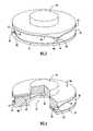
- FIGS. 5 and 6show an embodiment of the invention used as a gimbal, which pivots around mutually perpendicular axes.
- FIGS. 7 to 9show how the embodiment of FIGS. 5 and 6 may be mounted, and how tilting adjustments may be made.
- a flexure 2 of the prior artis shown.
- the flexureis ordinarily made out of a single block of elastic material 4 , which may be a metal.
- the shape of the blockis rectangular.
- the blockis cut in such a way as to form a pair of slits 6 and 8 .
- the interior ends of the slitsform entrances to respective cylindrical openings 10 and 12 which are formed by cylindrical walls 9 and 11 .
- the cylindrical openingspass completely through the block from front to back in FIG. 1 , and have a cross-sectional shape having a boundary which is a circular curve.
- a neck 18lies between openings 10 and 12 , and when a force, depicted by arrow 20 in FIG. 1 is applied to the flexure it pivots around neck 18 and tilts.
- the flexuremay be used in various applications.
- surface 22may bear a mirror, and the flexure may be used for positional adjustment of the mirror, or in an active application such as scanning the mirror.
- a difficulty with the prior art flexure of FIG. 1is that the requirement to prevent yielding of the high stress area in the neck limits by too much the degree of tilting which is available.
- FIGS. 2 and 3An embodiment of the invention is depicted in FIGS. 2 and 3 , wherein primed reference numerals which correspond with the reference numerals of FIG. 1 are used to identify like parts.
- flexure 2 ′is shown which is made from block 4 ′ of elastic material.
- First and second slits 6 ′ and 8 ′are present in the block, and the interior ends of the respective slits form entrances to first and second cylindrical openings 10 ′ and 12 ′ which are formed by cylindrical walls 9 ′ and 11 ′.
- the cross-sectional shape of cylindrical openings 10 ′ and 12 ′has a boundary which is curved and elongated rather than circular.
- openings 10 ′ and 12 ′pass through the block from front to back, and neck 18 ′ lies between the openings. Referring to FIG. 3 , it will be observed that when a force depicted by arrow 20 ′ is applied, the flexure tilts around a pivot region in neck 18 ′.
- FIG. 4is an enlarged front view of part of the flexure which illustrates the orientation of elongated openings 10 ′ and 12 ′.
- the shortest dimension of neck 18 ′extends directly between the two openings at the narrowest region of the neck, and is depicted by line 22 .
- the long dimension of the neckis transverse to the shortest dimension, and is represented by line 24 .
- the cross-sectional shape of openings 10 ′ and 12 ′has boundaries 13 and 15 respectively which are elongated in a direction parallel to the long dimension of the neck.
- the term “elongated” as used hereinmeans that the longest dimension of the boundary in a direction parallel to the long dimension of the neck is at least 1.25 times as great as the short dimension of the boundary which is perpendicular to and which bisects the longest dimension. These dimensions are depicted by lines 25 and 27 in FIG. 4 . It is noted that the term “boundary” as used herein includes a line which follows the boundary curve and makes a connection across the slit.
- the boundarymay be an elliptical or parabolic curve, although if the flexure is small, parabolic openings may be difficult to make. Openings of elliptical cross-section have an eccentricity of greater than 0.69 and less than 0.96 for best results.
- FIG. 1 flexureis machined out of aluminum block 2.0′′ ⁇ 2.0′′ ⁇ 1.0′′ thick with two 0.375′′ openings of circular cross-section 0.014′′ apart at the narrowest point.
- the blockis slitted horizontally 0.080′′ wide to provide rotation.
- a minimum deflection of 0.040′′ at the tipis desired, which results in a 2.3° rotation.
- the stressis just under 35k psi, the deflection is only 0.0267′′.
- the yield stress for 6061-T6 aluminumis 35k psi.
- FIG. 1FIG. 2 Stress (psi) 34350 29230 Deflection (in.) .0267 .04356
- the stress in the neck in the case of the FIG. 1 designis just about yielding and the deflection is only 0.0267′′, whereas 0.040′′ is required. To achieve the desired deflection, the flexure would definitely yield.
- the stress in the neck in the case of the FIG. 2 embodimentis only 29230 PSI and the desired deflection of 0.040′′ has been exceeded. Thus, much better results are achieved with use of the invention.
- the inventionmay be used in electro-optical systems having a requirement for large deflection angles or where continuous or repeated operation such as scanning is required.
- the force applied to the flexure to achieve tiltingmay be of various types including but not limited to mechanical, electric actuator, magnetic, electromagnetic, or pneumatic.
- the flexure of the preferred embodiment of the inventionincludes two slits per elongated opening, it may possible to use a flexure having one slit per opening in some applications.
- the use of the inventionis not limited to electro-optical systems as it may be used in various types of systems where tilting is required.
- a further embodiment of the inventionis shown where the layout of the flexure is annular rather than rectangular.
- a flexuremay be in the nature of a gimbal which provides a compound tilt angle adjustment in mutually perpendicular directions.
- such a flexuremay be used to provide a precision adjustment of optical elements such as laser end mirrors.
- block 30has a cross-section which is annular in shape. Cavity 32 is surrounded by the annular block, and mirror 34 may be mounted, for example, by recessing it in the cavity. Referring to FIG. 5 , neck 36 lies between cylindrical openings 38 and 40 , and in accordance with the invention, these openings have a cross-sectional shape which is curved and elongated.
- a section of neck 36is shown. There is another neck lying between a second pair of openings 180° displaced from neck 36 (not shown). Additionally, slit 42 connects opening 38 with an opening of the second pair of openings while slit 44 connects opening 40 with the other opening of the second pair of openings.
- the slitsare cut all the way through the annular block as are the openings, so when a force 46 is applied 90° displaced from neck 36 , the flexure pivots around both necks and tilts.
- a further neck 48is shown 90° displaced from neck 36 , which lies between openings 50 and 52 .
- FIGS. 7 to 9an approach to mounting the gimbal of FIGS. 5 and 6 is depicted, as well as of providing adjustment of the compound tilt angle.
- mounting plate 60is shown, which has mounting holes 62 .
- There are corresponding holes 64 in the flexurewhich are threaded, and screws 66 are used to secure the flexure to the mounting plate.
- the mounting platealso includes threaded holes 67 through which adjustment screws 68 and 70 pass.
- Adjustment holes 74 and 76which are clearance holes, are provided in the flexure, and screws 68 and 70 pass through these holes to provide tilt angle adjustment.
- screws 68provide adjustment around the axis of neck 48 .
- Holes 74are drilled deep enough to traverse slits 54 and 56 , and one of the screws 68 may be tightened while the other is in the unscrewed state until the desired tilt angle is reached. At that point, the other of the screw is screwed in just enough to touch the contact surface, so as to retain the flexure in place at the desired tilt angle.
- FIG. 8depicts the flexure as mounted on the mounting plate 60 , and is partially cut away to show the depths to which the adjustment screws penetrate.
- FIG. 9depicts the flexure as it appears when mounted.
- the flexure of the present inventionmay be made from a block of metal by an electric discharge method.
- a consumable wireis used, which may be computer controlled to generate the correct shape.
- an electrodewhich is pre-formed in the shape of the desired design may be utilized. It also may be possible to make the design by drilling, sawing, and milling operations.
Landscapes
- Engineering & Computer Science (AREA)
- General Engineering & Computer Science (AREA)
- Physics & Mathematics (AREA)
- Mechanical Engineering (AREA)
- General Physics & Mathematics (AREA)
- Optics & Photonics (AREA)
- Mechanical Light Control Or Optical Switches (AREA)
- Mounting And Adjusting Of Optical Elements (AREA)
- Micromachines (AREA)
Abstract
Description
| FIG. 1 | FIG. 2 | ||
| Stress (psi) | 34350 | 29230 | ||
| Deflection (in.) | .0267 | .04356 | ||
Claims (5)
Priority Applications (6)
| Application Number | Priority Date | Filing Date | Title |
|---|---|---|---|
| US12/210,457US8240941B2 (en) | 2008-09-15 | 2008-09-15 | Flexure with elongated openings |
| AU2009213002AAU2009213002B2 (en) | 2008-09-15 | 2009-09-08 | Flexure with elongated openings |
| EP09169959AEP2163930B1 (en) | 2008-09-15 | 2009-09-10 | Flexure with elongated openings |
| ES09169959TES2398558T3 (en) | 2008-09-15 | 2009-09-10 | Flexor device with elongated openings |
| CA2678435ACA2678435C (en) | 2008-09-15 | 2009-09-11 | Flexure with elongated openings |
| JP2009212542AJP5367515B2 (en) | 2008-09-15 | 2009-09-14 | Flexure with elongated opening |
Applications Claiming Priority (1)
| Application Number | Priority Date | Filing Date | Title |
|---|---|---|---|
| US12/210,457US8240941B2 (en) | 2008-09-15 | 2008-09-15 | Flexure with elongated openings |
Publications (2)
| Publication Number | Publication Date |
|---|---|
| US20100067980A1 US20100067980A1 (en) | 2010-03-18 |
| US8240941B2true US8240941B2 (en) | 2012-08-14 |
Family
ID=41276715
Family Applications (1)
| Application Number | Title | Priority Date | Filing Date |
|---|---|---|---|
| US12/210,457Active2029-12-04US8240941B2 (en) | 2008-09-15 | 2008-09-15 | Flexure with elongated openings |
Country Status (6)
| Country | Link |
|---|---|
| US (1) | US8240941B2 (en) |
| EP (1) | EP2163930B1 (en) |
| JP (1) | JP5367515B2 (en) |
| AU (1) | AU2009213002B2 (en) |
| CA (1) | CA2678435C (en) |
| ES (1) | ES2398558T3 (en) |
Cited By (4)
| Publication number | Priority date | Publication date | Assignee | Title |
|---|---|---|---|---|
| US10048205B2 (en) | 2016-04-14 | 2018-08-14 | Saudi Arabian Oil Company | Characterizing petroleum product contamination using fluorescence signal |
| US10281401B2 (en) | 2016-04-14 | 2019-05-07 | Saudi Arabian Oil Company | Opto-mechanical part for parabolic mirror fine rotation and on-axis linear positioning |
| US11441598B2 (en)* | 2018-12-20 | 2022-09-13 | Raytheon Company | Dual-axis flexure gimbal device |
| US12385521B1 (en)* | 2023-04-11 | 2025-08-12 | Caes Systems Llc | Flexure assembly |
Families Citing this family (4)
| Publication number | Priority date | Publication date | Assignee | Title |
|---|---|---|---|---|
| US8899869B2 (en)* | 2010-08-09 | 2014-12-02 | Michael Valois | Rotary flexure bearing |
| FR2996890B1 (en)* | 2012-10-12 | 2014-12-12 | Sagem Defense Securite | SUPPORT ASSEMBLY OF AN ORIENTABLE ELEMENT, AND OPTICAL EQUIPMENT INCORPORATING SUCH AN ASSEMBLY |
| ES2599398B1 (en)* | 2016-09-01 | 2017-08-08 | Consorci Per A La Construcció, Equipament I Explotació Del Laboratori De Llum De Sincrotró | ARTICULATION DEVICE |
| US11822146B2 (en)* | 2021-02-18 | 2023-11-21 | Raytheon Company | Fast steering monolithic dual axis mirror and method for manufacturing |
Citations (16)
| Publication number | Priority date | Publication date | Assignee | Title |
|---|---|---|---|---|
| US2937053A (en) | 1958-02-03 | 1960-05-17 | Task Corp | Frictionless pivot |
| US3217536A (en) | 1961-02-16 | 1965-11-16 | Garrett Corp | Force vector transducer |
| US3384424A (en) | 1966-12-29 | 1968-05-21 | Task Corp | External cross strap elastic pivot |
| US3420582A (en)* | 1964-07-22 | 1969-01-07 | Toroid Corp | Universal flexure type joint |
| US3597938A (en)* | 1969-05-21 | 1971-08-10 | Singer General Precision | Flexure joint |
| US3700291A (en) | 1971-10-29 | 1972-10-24 | Nasa | Two degree inverted flexure |
| US3700290A (en) | 1971-04-05 | 1972-10-24 | Singer Co | Flexure hinge assembly |
| US4100813A (en) | 1976-05-13 | 1978-07-18 | The Singer Company | Flexure suspension assembly |
| GB1538805A (en) | 1976-04-05 | 1979-01-24 | Litton Industries Inc | Flexure hinge assembly and method of manufacture thereof |
| US4143451A (en)* | 1976-04-05 | 1979-03-13 | Litton Systems, Inc. | Method of manufacturing a flexure hinge assembly |
| US4286370A (en)* | 1977-08-05 | 1981-09-01 | Incosym, Inc. | Universal joint flexure hinge suspension system, and method for manufacturing this system |
| US4528864A (en) | 1980-05-19 | 1985-07-16 | Incosym, Inc. | Universal joint flexure hinge suspension system and method for manufacturing this system |
| EP1013949A1 (en) | 1998-12-17 | 2000-06-28 | Sysmelec SA | Flexible pivot with large pivot angle and elevated rigidity |
| US6094288A (en) | 1998-12-08 | 2000-07-25 | Psc Scanning, Inc. | Scanner dither actuator with mirror mounting elements molded into spring |
| US6479782B1 (en)* | 2000-08-09 | 2002-11-12 | Goodrich Corporation | Fabrication of a brazeless cross-blade flexure block |
| US20090016810A1 (en) | 2005-08-19 | 2009-01-15 | Harald Geiger | Linear guide |
Family Cites Families (1)
| Publication number | Priority date | Publication date | Assignee | Title |
|---|---|---|---|---|
| JPH0375518A (en)* | 1989-08-18 | 1991-03-29 | Tokimec Inc | Flexible coupling type supporting apparatus and biaxial freedom-degree gyroscope having same apparatus |
- 2008
- 2008-09-15USUS12/210,457patent/US8240941B2/enactiveActive
- 2009
- 2009-09-08AUAU2009213002Apatent/AU2009213002B2/enactiveActive
- 2009-09-10EPEP09169959Apatent/EP2163930B1/enactiveActive
- 2009-09-10ESES09169959Tpatent/ES2398558T3/enactiveActive
- 2009-09-11CACA2678435Apatent/CA2678435C/enactiveActive
- 2009-09-14JPJP2009212542Apatent/JP5367515B2/ennot_activeExpired - Fee Related
Patent Citations (16)
| Publication number | Priority date | Publication date | Assignee | Title |
|---|---|---|---|---|
| US2937053A (en) | 1958-02-03 | 1960-05-17 | Task Corp | Frictionless pivot |
| US3217536A (en) | 1961-02-16 | 1965-11-16 | Garrett Corp | Force vector transducer |
| US3420582A (en)* | 1964-07-22 | 1969-01-07 | Toroid Corp | Universal flexure type joint |
| US3384424A (en) | 1966-12-29 | 1968-05-21 | Task Corp | External cross strap elastic pivot |
| US3597938A (en)* | 1969-05-21 | 1971-08-10 | Singer General Precision | Flexure joint |
| US3700290A (en) | 1971-04-05 | 1972-10-24 | Singer Co | Flexure hinge assembly |
| US3700291A (en) | 1971-10-29 | 1972-10-24 | Nasa | Two degree inverted flexure |
| GB1538805A (en) | 1976-04-05 | 1979-01-24 | Litton Industries Inc | Flexure hinge assembly and method of manufacture thereof |
| US4143451A (en)* | 1976-04-05 | 1979-03-13 | Litton Systems, Inc. | Method of manufacturing a flexure hinge assembly |
| US4100813A (en) | 1976-05-13 | 1978-07-18 | The Singer Company | Flexure suspension assembly |
| US4286370A (en)* | 1977-08-05 | 1981-09-01 | Incosym, Inc. | Universal joint flexure hinge suspension system, and method for manufacturing this system |
| US4528864A (en) | 1980-05-19 | 1985-07-16 | Incosym, Inc. | Universal joint flexure hinge suspension system and method for manufacturing this system |
| US6094288A (en) | 1998-12-08 | 2000-07-25 | Psc Scanning, Inc. | Scanner dither actuator with mirror mounting elements molded into spring |
| EP1013949A1 (en) | 1998-12-17 | 2000-06-28 | Sysmelec SA | Flexible pivot with large pivot angle and elevated rigidity |
| US6479782B1 (en)* | 2000-08-09 | 2002-11-12 | Goodrich Corporation | Fabrication of a brazeless cross-blade flexure block |
| US20090016810A1 (en) | 2005-08-19 | 2009-01-15 | Harald Geiger | Linear guide |
Non-Patent Citations (1)
| Title |
|---|
| Extended European Search Report in counterpart Application No. EP 09169959.5, dated Dec. 11, 2009. |
Cited By (6)
| Publication number | Priority date | Publication date | Assignee | Title |
|---|---|---|---|---|
| US10048205B2 (en) | 2016-04-14 | 2018-08-14 | Saudi Arabian Oil Company | Characterizing petroleum product contamination using fluorescence signal |
| US10281401B2 (en) | 2016-04-14 | 2019-05-07 | Saudi Arabian Oil Company | Opto-mechanical part for parabolic mirror fine rotation and on-axis linear positioning |
| US10712269B2 (en) | 2016-04-14 | 2020-07-14 | Saudi Arabian Oil Company | Optomechanical part for parabolic mirror fine rotation and on-axis linear positioning |
| US11255788B2 (en) | 2016-04-14 | 2022-02-22 | Saudi Arabian Oil Company | Optomechanical part for parabolic mirror fine rotation and on-axis linear positioning |
| US11441598B2 (en)* | 2018-12-20 | 2022-09-13 | Raytheon Company | Dual-axis flexure gimbal device |
| US12385521B1 (en)* | 2023-04-11 | 2025-08-12 | Caes Systems Llc | Flexure assembly |
Also Published As
| Publication number | Publication date |
|---|---|
| CA2678435A1 (en) | 2010-03-15 |
| ES2398558T3 (en) | 2013-03-20 |
| JP2010066771A (en) | 2010-03-25 |
| EP2163930B1 (en) | 2012-11-07 |
| AU2009213002B2 (en) | 2011-10-06 |
| JP5367515B2 (en) | 2013-12-11 |
| CA2678435C (en) | 2014-02-04 |
| AU2009213002A1 (en) | 2010-04-01 |
| US20100067980A1 (en) | 2010-03-18 |
| EP2163930A1 (en) | 2010-03-17 |
Similar Documents
| Publication | Publication Date | Title |
|---|---|---|
| US8240941B2 (en) | Flexure with elongated openings | |
| US10598924B2 (en) | Cross flexure suspension system | |
| US6754013B2 (en) | Adjustable mount for optical components | |
| US7679845B2 (en) | Adjustable/non-adjustable precision optical mounts | |
| CN110262036B (en) | A two-dimensional large-angle fast deflection mirror | |
| US10670825B2 (en) | Mounting devices with integrated alignment adjustment features and locking mechanisms | |
| US10443649B2 (en) | Flexural pivot | |
| US20050046979A1 (en) | Precision mirror displacement assembly | |
| JP7514608B2 (en) | Pivot deflection with uniform moment stiffness | |
| US20180217349A1 (en) | Diffraction grating gimbal mount | |
| US11441598B2 (en) | Dual-axis flexure gimbal device | |
| CN107615124A (en) | Integral Optical Mounting Elements | |
| KR20200031051A (en) | Support apparatus | |
| US5590149A (en) | Mirror mount | |
| US4818089A (en) | Kinematic resonator support | |
| US20190058237A1 (en) | Apparatus and method for providing linear motion of a device | |
| US10605340B2 (en) | Angular motion transfer driven by ball bearings | |
| EP1418455A1 (en) | Vertical fine movement mechanism of microscope | |
| JP2002277755A (en) | Reflector device | |
| US4901966A (en) | Kinematic resonator support | |
| KR20220161907A (en) | A flexible mechanism for realizing out-of-plane 3 degrees of freedom precision motion | |
| JPS63127218A (en) | Direction adjusting device for light beam changing mirror | |
| JPH11174303A (en) | Structure for fitting lens | |
| JPH11174299A (en) | Lens barrel | |
| CN111273416A (en) | Adjusting device in laser optical system |
Legal Events
| Date | Code | Title | Description |
|---|---|---|---|
| AS | Assignment | Owner name:ITT MANUFACTURING ENTERPRISES, INC.,DELAWARE Free format text:ASSIGNMENT OF ASSIGNORS INTEREST;ASSIGNOR:KIBEL, EDMOND;REEL/FRAME:021543/0034 Effective date:20080911 Owner name:ITT MANUFACTURING ENTERPRISES, INC., DELAWARE Free format text:ASSIGNMENT OF ASSIGNORS INTEREST;ASSIGNOR:KIBEL, EDMOND;REEL/FRAME:021543/0034 Effective date:20080911 | |
| AS | Assignment | Owner name:EXELIS INC., VIRGINIA Free format text:ASSIGNMENT OF ASSIGNORS INTEREST;ASSIGNOR:ITT MANUFACTURING ENTERPRISES LLC (FORMERLY KNOWN AS ITT MANUFACTURING ENTERPRISES, INC.);REEL/FRAME:027604/0136 Effective date:20111221 | |
| STCF | Information on status: patent grant | Free format text:PATENTED CASE | |
| CC | Certificate of correction | ||
| FPAY | Fee payment | Year of fee payment:4 | |
| AS | Assignment | Owner name:HARRIS CORPORATION, FLORIDA Free format text:MERGER;ASSIGNOR:EXELIS INC.;REEL/FRAME:039362/0534 Effective date:20151223 | |
| MAFP | Maintenance fee payment | Free format text:PAYMENT OF MAINTENANCE FEE, 8TH YEAR, LARGE ENTITY (ORIGINAL EVENT CODE: M1552); ENTITY STATUS OF PATENT OWNER: LARGE ENTITY Year of fee payment:8 | |
| MAFP | Maintenance fee payment | Free format text:PAYMENT OF MAINTENANCE FEE, 12TH YEAR, LARGE ENTITY (ORIGINAL EVENT CODE: M1553); ENTITY STATUS OF PATENT OWNER: LARGE ENTITY Year of fee payment:12 |