US8240533B2 - Automated air-pillow dispenser - Google Patents
Automated air-pillow dispenserDownload PDFInfo
- Publication number
- US8240533B2 US8240533B2US11/867,452US86745207AUS8240533B2US 8240533 B2US8240533 B2US 8240533B2US 86745207 AUS86745207 AUS 86745207AUS 8240533 B2US8240533 B2US 8240533B2
- Authority
- US
- United States
- Prior art keywords
- pillows
- chain
- transfer apparatus
- traction members
- pillow
- Prior art date
- Legal status (The legal status is an assumption and is not a legal conclusion. Google has not performed a legal analysis and makes no representation as to the accuracy of the status listed.)
- Active, expires
Links
- 239000005022packaging materialSubstances0.000claimsabstractdescription10
- 230000007246mechanismEffects0.000claimsdescription73
- 239000000463materialSubstances0.000claimsdescription31
- 238000000034methodMethods0.000abstractdescription10
- 238000000926separation methodMethods0.000abstractdescription7
- 238000012856packingMethods0.000abstractdescription6
- 230000008569processEffects0.000abstractdescription4
- 230000000994depressogenic effectEffects0.000abstractdescription3
- 239000011800void materialSubstances0.000abstractdescription2
- 238000004806packaging method and processMethods0.000description16
- 238000004519manufacturing processMethods0.000description7
- 238000007789sealingMethods0.000description5
- 238000005520cutting processMethods0.000description4
- 230000011514reflexEffects0.000description3
- 230000005540biological transmissionEffects0.000description2
- 238000012986modificationMethods0.000description2
- 230000004048modificationEffects0.000description2
- 230000000717retained effectEffects0.000description2
- 238000003860storageMethods0.000description2
- 241001553178Arachis glabrataSpecies0.000description1
- VGGSQFUCUMXWEO-UHFFFAOYSA-NEtheneChemical compoundC=CVGGSQFUCUMXWEO-UHFFFAOYSA-N0.000description1
- 241001643597EvasSpecies0.000description1
- CWYNVVGOOAEACU-UHFFFAOYSA-NFe2+Chemical compound[Fe+2]CWYNVVGOOAEACU-UHFFFAOYSA-N0.000description1
- 230000004913activationEffects0.000description1
- 230000009286beneficial effectEffects0.000description1
- 230000008901benefitEffects0.000description1
- 230000003247decreasing effectEffects0.000description1
- 239000004744fabricSubstances0.000description1
- 239000012530fluidSubstances0.000description1
- 239000006260foamSubstances0.000description1
- 229920001903high density polyethylenePolymers0.000description1
- 239000004700high-density polyethyleneSubstances0.000description1
- 230000001788irregularEffects0.000description1
- 239000010985leatherSubstances0.000description1
- 229920000092linear low density polyethylenePolymers0.000description1
- 239000004707linear low-density polyethyleneSubstances0.000description1
- 229920001684low density polyethylenePolymers0.000description1
- 239000004702low-density polyethyleneSubstances0.000description1
- 239000000203mixtureSubstances0.000description1
- 239000013518molded foamSubstances0.000description1
- 239000011105molded pulpSubstances0.000description1
- 230000003287optical effectEffects0.000description1
- 230000010355oscillationEffects0.000description1
- 239000000123paperSubstances0.000description1
- 235000020232peanutNutrition0.000description1
- 229920003023plasticPolymers0.000description1
- 239000004033plasticSubstances0.000description1
- 229920001200poly(ethylene-vinyl acetate)Polymers0.000description1
- 229920013716polyethylene resinPolymers0.000description1
- 230000002028prematureEffects0.000description1
- 230000002441reversible effectEffects0.000description1
- 239000002356single layerSubstances0.000description1
- 239000007787solidSubstances0.000description1
- 125000006850spacer groupChemical group0.000description1
- 230000007480spreadingEffects0.000description1
- 238000003892spreadingMethods0.000description1
- 230000007704transitionEffects0.000description1
- 230000007723transport mechanismEffects0.000description1
- 238000011144upstream manufacturingMethods0.000description1
Images


Classifications
- B—PERFORMING OPERATIONS; TRANSPORTING
- B65—CONVEYING; PACKING; STORING; HANDLING THIN OR FILAMENTARY MATERIAL
- B65H—HANDLING THIN OR FILAMENTARY MATERIAL, e.g. SHEETS, WEBS, CABLES
- B65H20/00—Advancing webs
- B—PERFORMING OPERATIONS; TRANSPORTING
- B31—MAKING ARTICLES OF PAPER, CARDBOARD OR MATERIAL WORKED IN A MANNER ANALOGOUS TO PAPER; WORKING PAPER, CARDBOARD OR MATERIAL WORKED IN A MANNER ANALOGOUS TO PAPER
- B31D—MAKING ARTICLES OF PAPER, CARDBOARD OR MATERIAL WORKED IN A MANNER ANALOGOUS TO PAPER, NOT PROVIDED FOR IN SUBCLASSES B31B OR B31C
- B31D5/00—Multiple-step processes for making three-dimensional articles ; Making three-dimensional articles
- B31D5/0039—Multiple-step processes for making three-dimensional articles ; Making three-dimensional articles for making dunnage or cushion pads
- B31D5/0073—Multiple-step processes for making three-dimensional articles ; Making three-dimensional articles for making dunnage or cushion pads including pillow forming
- B—PERFORMING OPERATIONS; TRANSPORTING
- B65—CONVEYING; PACKING; STORING; HANDLING THIN OR FILAMENTARY MATERIAL
- B65B—MACHINES, APPARATUS OR DEVICES FOR, OR METHODS OF, PACKAGING ARTICLES OR MATERIALS; UNPACKING
- B65B55/00—Preserving, protecting or purifying packages or package contents in association with packaging
- B65B55/20—Embedding contents in shock-absorbing media, e.g. plastic foam, granular material
- B—PERFORMING OPERATIONS; TRANSPORTING
- B65—CONVEYING; PACKING; STORING; HANDLING THIN OR FILAMENTARY MATERIAL
- B65H—HANDLING THIN OR FILAMENTARY MATERIAL, e.g. SHEETS, WEBS, CABLES
- B65H20/00—Advancing webs
- B65H20/005—Electrical drive motor control devices therefor
- B—PERFORMING OPERATIONS; TRANSPORTING
- B65—CONVEYING; PACKING; STORING; HANDLING THIN OR FILAMENTARY MATERIAL
- B65H—HANDLING THIN OR FILAMENTARY MATERIAL, e.g. SHEETS, WEBS, CABLES
- B65H20/00—Advancing webs
- B65H20/02—Advancing webs by friction roller
- B—PERFORMING OPERATIONS; TRANSPORTING
- B65—CONVEYING; PACKING; STORING; HANDLING THIN OR FILAMENTARY MATERIAL
- B65H—HANDLING THIN OR FILAMENTARY MATERIAL, e.g. SHEETS, WEBS, CABLES
- B65H20/00—Advancing webs
- B65H20/06—Advancing webs by friction band
- B—PERFORMING OPERATIONS; TRANSPORTING
- B31—MAKING ARTICLES OF PAPER, CARDBOARD OR MATERIAL WORKED IN A MANNER ANALOGOUS TO PAPER; WORKING PAPER, CARDBOARD OR MATERIAL WORKED IN A MANNER ANALOGOUS TO PAPER
- B31D—MAKING ARTICLES OF PAPER, CARDBOARD OR MATERIAL WORKED IN A MANNER ANALOGOUS TO PAPER, NOT PROVIDED FOR IN SUBCLASSES B31B OR B31C
- B31D2205/00—Multiple-step processes for making three-dimensional articles
- B31D2205/0005—Multiple-step processes for making three-dimensional articles for making dunnage or cushion pads
- B31D2205/0011—Multiple-step processes for making three-dimensional articles for making dunnage or cushion pads including particular additional operations
- B31D2205/0052—Perforating; Forming lines of weakness
- B—PERFORMING OPERATIONS; TRANSPORTING
- B31—MAKING ARTICLES OF PAPER, CARDBOARD OR MATERIAL WORKED IN A MANNER ANALOGOUS TO PAPER; WORKING PAPER, CARDBOARD OR MATERIAL WORKED IN A MANNER ANALOGOUS TO PAPER
- B31D—MAKING ARTICLES OF PAPER, CARDBOARD OR MATERIAL WORKED IN A MANNER ANALOGOUS TO PAPER, NOT PROVIDED FOR IN SUBCLASSES B31B OR B31C
- B31D2205/00—Multiple-step processes for making three-dimensional articles
- B31D2205/0005—Multiple-step processes for making three-dimensional articles for making dunnage or cushion pads
- B31D2205/0011—Multiple-step processes for making three-dimensional articles for making dunnage or cushion pads including particular additional operations
- B31D2205/0058—Cutting; Individualising the final products
- B—PERFORMING OPERATIONS; TRANSPORTING
- B31—MAKING ARTICLES OF PAPER, CARDBOARD OR MATERIAL WORKED IN A MANNER ANALOGOUS TO PAPER; WORKING PAPER, CARDBOARD OR MATERIAL WORKED IN A MANNER ANALOGOUS TO PAPER
- B31D—MAKING ARTICLES OF PAPER, CARDBOARD OR MATERIAL WORKED IN A MANNER ANALOGOUS TO PAPER, NOT PROVIDED FOR IN SUBCLASSES B31B OR B31C
- B31D2205/00—Multiple-step processes for making three-dimensional articles
- B31D2205/0005—Multiple-step processes for making three-dimensional articles for making dunnage or cushion pads
- B31D2205/0011—Multiple-step processes for making three-dimensional articles for making dunnage or cushion pads including particular additional operations
- B31D2205/007—Delivering
- B—PERFORMING OPERATIONS; TRANSPORTING
- B31—MAKING ARTICLES OF PAPER, CARDBOARD OR MATERIAL WORKED IN A MANNER ANALOGOUS TO PAPER; WORKING PAPER, CARDBOARD OR MATERIAL WORKED IN A MANNER ANALOGOUS TO PAPER
- B31D—MAKING ARTICLES OF PAPER, CARDBOARD OR MATERIAL WORKED IN A MANNER ANALOGOUS TO PAPER, NOT PROVIDED FOR IN SUBCLASSES B31B OR B31C
- B31D2205/00—Multiple-step processes for making three-dimensional articles
- B31D2205/0005—Multiple-step processes for making three-dimensional articles for making dunnage or cushion pads
- B31D2205/0076—Multiple-step processes for making three-dimensional articles for making dunnage or cushion pads involving particular machinery details
- B31D2205/0082—General layout of the machinery or relative arrangement of its subunits
- Y—GENERAL TAGGING OF NEW TECHNOLOGICAL DEVELOPMENTS; GENERAL TAGGING OF CROSS-SECTIONAL TECHNOLOGIES SPANNING OVER SEVERAL SECTIONS OF THE IPC; TECHNICAL SUBJECTS COVERED BY FORMER USPC CROSS-REFERENCE ART COLLECTIONS [XRACs] AND DIGESTS
- Y10—TECHNICAL SUBJECTS COVERED BY FORMER USPC
- Y10T—TECHNICAL SUBJECTS COVERED BY FORMER US CLASSIFICATION
- Y10T225/00—Severing by tearing or breaking
- Y10T225/10—Methods
- Y10T225/12—With preliminary weakening
- Y—GENERAL TAGGING OF NEW TECHNOLOGICAL DEVELOPMENTS; GENERAL TAGGING OF CROSS-SECTIONAL TECHNOLOGIES SPANNING OVER SEVERAL SECTIONS OF THE IPC; TECHNICAL SUBJECTS COVERED BY FORMER USPC CROSS-REFERENCE ART COLLECTIONS [XRACs] AND DIGESTS
- Y10—TECHNICAL SUBJECTS COVERED BY FORMER USPC
- Y10T—TECHNICAL SUBJECTS COVERED BY FORMER US CLASSIFICATION
- Y10T225/00—Severing by tearing or breaking
- Y10T225/30—Breaking or tearing apparatus
- Y10T225/393—Web restrainer
Definitions
- the present inventionrelates to packaging materials and more particularly is directed to systems and methods used in the manufacturing and utilization of packaging pillows.
- a technique that has gained recent popularityinvolves the use of air-inflated cushions formed from a film material (“pillows”), such as disclosed in U.S. Pat. No. 6,932,134 and pending application Ser. No. 11/185,927.
- This style of packagingallows low-volume, uninflated pillow film materials to be shipped to packers, who then inflate the pillows as needed into shock-absorbing packing material.
- Pillow inflating machinesmay be used at the point of packaging to provide fully formed pillows at the time of packaging, thereby eliminating the need to store bulky packaging materials at the packaging site.
- the inflated pillowsare formed in a continuous strip of individual pillows, and the desired length or number of the inflated pillows are separated from the continuous strip of inflated pillows as they are dispensed from the pillow inflating machine.
- Air inflating machine systemsmay produce the air-inflated pillows at a rate that differs from the rate at which the actual packaging of goods is occurring.
- the strip of formed packaging materialis often fed into a holding bin adjacent to the inflation device.
- packing materialis needed by the packer, the end of the continuous strip of inflated pillows is withdrawn from the holding bin, an appropriate length of inflated pillows is measured by the packer, separated from the continuous strip and then placed into a shipping box to protect the packaged goods.
- a packerWhen a packer is using the pillows as packaging material, he must pull the required material out of the holding bin, typically using both hands to pull and place a number of pillows into the shipping box to fill any voids that may be present. When a sufficient number of pillows have been placed in the box to fill the voids, the packer must separate the pillows from the continuous strip of pillows.
- the need for the packer to reach into the holding bin and manually separate the required length or number of inflated pillowscan be a time-consuming and laborious process, decreasing the overall efficiency of the packaging operation and thereby increasing costs.
- a transfer standmay be placed in front of the holding bin with the end of the continuous strip of pillows draped over the transfer stand so that the packer does not have reach into the holding bin every time additional pillows are required. However, this still requires the packer to manually pull and tear the required number of pillows for packaging.
- a deviceis needed that can facilitate and improve the efficiency of dispensing air-inflated pillows to aid the packer in the packaging operation.
- a transfer and dispensing apparatusconveys and separates packaging material, cushions or pillows when needed by the operator.
- an operating switchsuch as a foot pedal is depressed to dispense pillows from the apparatus and into the box in a connected strip.
- the apparatusstops dispensing pillows, separates the continuous strip of pillows along a transverse perforation in the strip, and ejects the end of the separated segment.
- the packercan then complete packing the box by placing the severed end of the pillows into the box, advance to the next box, and repeat the process.
- the transfer and dispensing apparatusmay be positioned in any convenient location including adjacent to, above or attached to the inflation device.
- the inventionrelates to a packing material transfer apparatus.
- a preferred embodiment of the transfer apparatusincludes a plurality of traction members, such as grippers, that are configured for gripping a chain of pre-inflated pillows, which are connected to each other end to end.
- a driving mechanismis operably associated with the traction members to drive the traction members for drawing the chain from an input location to an output location, in which the pillows are dispensed.
- a motoris configured for powering the driving mechanism.
- the preferred traction membersare spaced at a pre-determined distance from each other, which distance corresponds to the position of recessed zones along the chain, for example, zones between the inflated pillows, such that the traction members are received within the recessed zones to engage and move the chain.
- a guide surfacecan be provided, which is configured for guiding the pillows therealong, and the driving mechanism can be configured for moving the traction members along a path adjacent to the guide surface for trapping the pillows therebetween.
- the guide surfacecan be stationary or movable and can be arcuate or have another suitable shape.
- the driving mechanismcan include a drum to which the traction members are mounted to drive the traction members along a curved, and preferably circular path, such as when using an arcuate guide surface.
- the guide surfaceis preferably driven for moving the chain cooperatively with the traction members.
- the guide surface and traction membersinclude rollers or driven belts, preferably extending on opposite sides of a longitudinal axis of the chain, and which can be arranged as conveyers.
- the preferred transfer apparatuspreferably includes a detachment mechanism that is configured for detaching at least one of the pillows from the chain.
- the detachment mechanismcan have a detachment element that is operable to break a weakened area between the adjacent pillows and the chain to separate the pillows from each other.
- the detached pillowscan be dispensed at the output location.
- the detachment elementincludes at least one cutter configured to rotate through the weakened area to separate adjacent pillows.
- the cutterincludes first and second cutters configured to rotate in opposite directions to cooperatively pull material of the chain of pillows around the weakened area against the cutters.
- a pillow detectorcan also be provided for detecting the position of individual or groups of pillows in the chain.
- the detectoris preferably connected for operating the detachment element to detach at least one pillow from the chain, in which this operation is activated based on the detected positions of the pillows.
- the pillow detectorcan include a follower configured and positioned to follow contours of the pillows to detect the positions thereof.
- the pillow detectorincludes a vacuum source configured to detect changes in vacuum depending on the region of the chain associated therewith as the chain is moved in relation thereto, thus enabling the vacuum source to be used to determine the positions of the pillows.
- the traction members of one embodimentinclude nip elements to grip the chain by nipping it.
- the driving mechanismcan be configured to rotate the nip elements for drawing the chain towards the output location.
- the nip elementscan include rollers and conveyers, for example.
- the traction memberscan include forward and aft traction members, with the driving mechanism configured for operating the forward and aft traction members at different speeds, such as by stopping one and moving the other or by moving each in different directions, to detach detachment of at least one pillow from the chain.
- the driving mechanismcan be configured for operating the forward and aft traction members at different speeds to initiate a tear between the pillow or pillows to be detached and the remainder of the chain at one or both of the lateral sides of the chain, so that the tear can continue across the remainder of the area between the pillows to be detached and the remainder of the chain.
- a pillow chain transfer systemis provided, in which two or more transfer apparatuses can be disposed and associated with respect to each other for transferring the chain from the output location of one of the transfer apparatuses to the output location to another of the transfer apparatuses.
- the inventionprovides a device that facilitates and improves the efficiency in handling chains of inflated pillows, which can be used for protecting packaged articles.
- FIG. 1is a side view of an automated transfer and dispensing apparatus in use alongside other components of an air inflated packaging pillow system;
- FIGS. 2A and 2Bare side views of another configuration of an air inflation packaging pillow system, with the automated transfer and dispensing apparatus in the lowered and raised positions, respectively;
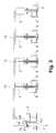
- FIG. 3is a side view of another configuration of an air inflation packaging system
- FIG. 4is a perspective view of a preferred embodiment of an air inflation packaging pillow system
- FIG. 5is a top view thereof
- FIG. 6is a cross-sectional, diagrammatic view of components of the automated transfer and dispensing apparatus at section 5 - 5 as identified in FIG. 5 ;
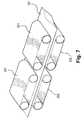
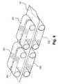
- FIGS. 7 and 8are perspective views of components of other embodiments of automated transfer and dispensing apparatuses.
- FIGS. 9 and 10are side views of components of other embodiments of automated transfer and dispensing apparatuses.
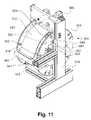
- FIGS. 11 and 12are front and rear side perspective views of an alternative embodiment of an automated transfer and dispensing apparatus
- FIG. 13Ais a perspective view of a drum thereof
- FIG. 13Bis a perspective view of another embodiment of a drum with biasing members
- FIG. 14is a rear, cut-away view of a cutting mechanism of the transfer and dispensing apparatus of FIGS. 11 and 12 ;
- FIG. 15is a side, cut-away view thereof
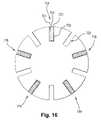
- FIG. 16is a side view of another embodiment of a drum with biasing members of an automated transfer and dispensing apparatus
- FIG. 17is rear view of another embodiment of a cutting mechanism
- FIGS. 18A and 18Bare perspective and side views of another embodiment of an automated transfer and dispensing apparatus
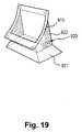
- FIG. 19is a perspective view of one embodiment of an intake funnel.
- FIG. 20is a top view of a typical web material used to form inflated pillows.
- FIG. 1a preferred embodiment of the transfer and dispensing apparatus 10 , which can be configured as an air-pillow burster, is shown positioned adjacent to and above the location of a holding bin 2 .
- the holding bin 2may be used to collect pillows 101 as they are inflated and sealed by a pillow inflation and sealing device 5 , for example, as disclosed in U.S. Pat. No. 6,932,134, the disclosure of which is incorporated herein by reference.
- the pillowsare only filled with a fluid, and more preferably a gas, such as air, and most preferably do not contain a substantial amount of solids therein.
- inflated pillows 101are formed by the pillow manufacturing devices, they fall into the holding bins in a continuous strip 100 .
- a sensor 6 associated with the holding bin 2may be used to identify the amount of inflated pillows 101 that have accumulated in the holding bin 2 or when the holding bin 2 is filled to a predetermined level, and give appropriate instructions to control the manufacture of additional pillows, such as by interrupting the making of pillows 101 by the pillow manufacturing device 5 .
- FIG. 20shows a typical web or strip 610 of uninflated material to be inflated and sealed into a series of pillows attached at perforated edges.
- the web 610may be made of a variety of different materials, including materials such as polyethylene resins such as LDPE, LLDPE, HDPE; metallocenes; EVAs; and blends thereof.
- the web 610has a top edge 612 and a bottom edge 614 , both of which are closed.
- the web 610includes generally transverse seals 616 and generally transverse perforations 618 .
- the transverse seals 616join a top sheet 620 of the web 610 to a bottom sheet 622 of the web 610 along the seals 616 , while the transverse perforations 618 perforate the web through the top and bottom sheets 620 and 622 .
- the transverse seals 616begin at the bottom edge 614 of the web 610 and extend to a distance d from the top edge 612 .
- the web 610has a width w, and a perforation-to-perforation length l, which may be altered depending on the particular type of pillow to be manufactured.
- the transfer and dispensing apparatus 10which is preferably configured to dispense the free end 102 of pillows 101 to the operator when needed.
- the sensor 6 on the holding bin 2can limit the transfer of inflated pillows 101 out of the holding bin 2 when supplies are low to prevent premature tearing of the continuous strip of pillows 100 .
- FIGS. 2A and 2Bshow another preferred embodiment of the transfer and dispensing apparatus 10 , shown as part of a larger air inflation packaging pillow system.
- FIG. 2Ashows a pillow inflation and sealing device 5 forming a strip of pillows 100 , which is fed into one end of the transfer and dispensing apparatus 10 .
- the apparatus 10is associated with, and preferably moveably mounted on, a support, such as an upright member, which is preferably a pole 3 .
- a drive mechanismis preferably associated with the apparatus 10 and the pole 3 , and configured for controlling movement of the apparatus 10 up and down the pole 3 .
- the drive mechanismcan be manually driven, such as by a pulley and lever system, or the drive mechanism can be powered, such as by an electric motor 4 , and can use other systems, such as a worm gear, powered pulleys, and actuators, such as pneumatic or hydraulic.
- FIG. 2Athe apparatus 10 is shown in the lowered position with respect to the pole 3 such that the lead end of the formed strip of pillows 100 can be easily fed into the apparatus by a standing or sitting operator, the loading position preferably being between about 2 and 7 feet off the floor.
- the apparatus 10is raised to a height on the pole 3 that is about at least as high as the top of a pillow holding bin 2 , which in this embodiment is positioned above a work station or assembly bench 8 .
- the apparatus 10can dispense strips of pillows 100 in desired lengths for storage in the holding bin 2 .
- the packermerely needs to reach into the bin, such as into an opening at the bottom of the holding bin 2 that is conveniently located above the assembly bench to retrieve multiple strips of pillows 100 as desired.
- the transfer and dispensing apparatus 10can alternatively be placed in a position away from either the pillow manufacturing device 5 , the holding bin 2 , or both.
- a conveyor mechanismcan be used to transfer the continuous strip of inflated pillows 100 from the inflation machine 5 to a holding bin 2 located some distance away. From there, the pillows 101 can be dispensed for availability to the packer.
- one or more of the apparatuses 10can be positioned in a system to convey pillows 101 to a remote location from the pillow manufacturing device 5 .
- the transfer apparatus 10 in FIG. 3is associated with an inflation and sealing device 5 for forming the strip of pillows 100 , and a conveyor mechanism that preferably includes a pneumatic duct or conveyer shaft 11 , a pillow transport mechanism such as a blower 7 , and a controller 9 , which are preferably configured to transport strips of pillows to various remotely located holding bins 2 .
- the shaft 11preferably extends to a height at least above the top of the holding bins 2 for dispensing the strip of pillows 100 therein, preferably leaving sufficient height thereunder for operators to walk pass.
- Positioning the shaft 11 at this elevated heightadvantageously allows the shaft to be clear of the working area below, which can be used for another processes or as a throughway for packages, machinery or people.
- the conveyerpreferably provides at least about 6.5 feet for operators to walk thereunder, although more or less can alternatively be provided, such as in embodiments in which it is not desired to provide a walkway thereunder.
- At least one diverter 13is associated with the shaft 11 , preferably adjacent to a holding bin 2 , and configured for diverting a strip of pillows from the shaft 11 into the holding bin 2 .
- the systemcan transport desired lengths of pillow strips 100 to remote holding bins 2 for storage therein.
- the apparatus 10can deliver a strip of pillows 10 into the shaft 11 , for example through shaft opening 12 , and the controller 9 can control the blower 7 to transport the strip 100 through the shaft.
- the controller 9also preferably controls the diverters 13 to determine to which holding bin the strip of pillows is delivered, and the diverters are configured to direct the pillows conveyed through the shaft into the selected bin.
- the systemcan maintain and refill the amount of pillows strips 100 that are contained in multiple holding bins located remotely from the transfer and dispensing apparatus 10 and inflation and sealing device 5 .
- An alternative embodimentemploys other types of conveyers, for example using conveyer belts to move the pillows.
- the preferred embodiment of the transfer and dispensing apparatus 10includes first and second motor support mounts 110 , 111 arranged on opposite sides of a pillow support and guide saddle 112 .
- the motor support mounts 110 , 111hold one or more motors, and preferably two motors 113 , 114 and 115 , 116 each, with each motor connected to and driving a pillow engagement or traction member, such as a pair of nip rollers 117 , 118 .
- the nip rollers 117 , 118are configured to grip the edge of the pillows 101 in order to move and manipulate the continuous strip of pillow material 100 as it is drawn through the apparatus 10 and dispensed to the user.
- Each nip roller 117 , 118can be driven directly by a motor 113 - 116 , or can be driven through a gearing mechanism.
- Other configurations for driving the nip rollersare well known and within the knowledge of those of skill in the art.
- An infeed/intake/inlet section 121(shown in FIG. 5 ) of the apparatus 10 is located adjacent to the feed nip rollers 117 , 118 and is tapered or flared to provide a smooth transition section from the holding bin 2 .
- the taper of the infeed section 121allows the continuous strip of pillows 101 to be drawn from the holding bin 2 without catching, breaking or tearing, for example.
- the infeed section 121is adjustable in both height and width to allow for pillows of differing inflated thickness and width. As it is drawn through the apparatus 10 , the continuous strip of inflated pillows 100 may rest on or be guided by the pillow support saddle 112 .
- the support saddle 112may be arcuately shaped to match the contour of the continuous strip of pillows 100 as it is drawn from the holding bin 2 .
- An edge guide plate 126defines a path for the edges of the pillows 101 through the apparatus 10 , and may be supported by the motor support mount 110 , 111 in a position between the feed nip rollers 117 , 118 and the dispensing nip rollers 119 , 120 .
- the motors 113 - 116operate at variable speeds and directions, and are controlled by a motor controller 20 .
- the motor controller 20controls the speed and direction of rotation of each of the motors 113 - 116 .
- the motor controller 20may receive instructions from the user via an operating switch, such as a foot pedal 21 .
- the motor controller 20may also receive instructions from other components of the system. For example, the above disclosed sensor 6 mounted on the holding bin 2 could instruct the motor controller 20 to stop the apparatus 10 from withdrawing pillows 101 from the holding bin 2 when the number of inflated pillows 101 is low.
- the motor controller 20coordinates the motors so that they work in unison to drive the pairs of nip rollers 117 - 120 in a way to manipulate the movement of pillows 101 in a desired manner.
- the nip rollers 117 - 120can be driven in unison so that the continuous strip of pillows 100 is drawn from the holding bin 2 , transferred through the apparatus 10 , and dispensed directly to the user in a continuous, steady rate for as long as the foot pedal 21 is depressed.
- the operatorreleases the foot pedal 21 and the nip rollers 117 - 120 are driven in a manner so that the feed nip rollers 117 , 118 rotate in one direction while the dispensing nip rollers 119 , 120 rotate in the opposite direction so as to pull the strip of pillows 100 apart and thus separate a desired length or number of pillows 101 from the continuous length of pillows 100 .
- the dispensing nip rollers 119 , 120can dispense the separated segment of pillow packaging material to the user.
- the left and right feed and/or dispensing rollerscan also move at different speeds to initiate a tear on one side.
- the infeed rollers 117 , 118can move in reverse to help tear the chain of pillows 101 .
- the feed nip rollers 117 , 118maintain the position of the leading edge 102 of the remaining continuous strip of pillows 101 , and keep it from falling back into the bin 2 or out of the apparatus 10 .
- the feed nip rollers 117 , 118then advance the leading edge 102 of the continuous strip 100 forward, the dispensing nip rollers 119 , 120 grip the leading edge 102 of the strip of pillows, and the apparatus 10 is again ready to dispense pillows for the packing of the next box.
- the preferred embodiment of the apparatus 10can use a follower arm 304 as the pillow position detector to identify the location of the perforation 104 between pillows 101 so that the strip 100 may be separated.
- the follower arm 304is mounted on a transverse shaft 305 extending between the first and second motor support mounts 110 , 111 , and can swivel about the axis of the transverse shaft 305 .
- the transverse shaft 305can be engaged to the follower arm 304 so that the shaft 305 also rotates about its longitudinal axis as the follower arm 304 swivels.
- a follower wheel 306is located at the end of the follower arm 304 and is able to roll over the inflated pillows 101 and follow the contour of the pillows as they move through the apparatus 10 . As the follower wheel 306 rolls along the contour of the pillow 101 , the wheel 306 will rise along the inflated pillow portions 105 and descend into the valleys 103 at the transverse borders between the pillows 101 .
- a springsuch as a coil spring, can be mounted on the transverse shaft 305 to dampen unwanted oscillations in the follower arm 304 as it swivels, and to keep the follower wheel 306 pressed against the surface of the pillows.
- a counterweight 307 mounted on the follower arm 304 , on the end opposite the follower wheel 306 ,may be used to counteract the weight of the follower wheel 306 and arm 304 , thereby keeping the follower arm 304 in balance about the transverse shaft 305 .
- a sensor 310 mounted at or near the end of the transverse shaft 305may respond to rotation of the shaft to send a signal to the motor controller 20 to signal when the follower wheel 306 is located in one of the valleys 103 between pillows 101 .
- the motor controller 20can stop the dispensing of pillows 101 .
- the driving mechanismstops the strip of pillows 100 at the location of the perforation 104 between the pillows, allowing the segment of pillows to be separated by the driving mechanism or one of the other identified separation mechanisms.
- the nip rollerscan be adjusted in relation to one another, such as in horizontal and vertical directions “a” and “b,” for example, to accommodate for differences in height and width of the pillow film material, and for feeding material into the apparatus 10 .
- the nip rollerscan also be positioned and spaced to squeeze the lateral sides 101 a , 101 b of inflated portion of the pillows 101 in a manner so as to fully pressurize or increase the pressurization of at least the center section of the inflated pillow 101 as it is drawn through the apparatus 10 .
- thisincreases the height and rigidity of the pillows, and can ensure that at least the center section 105 of the pillow 101 is fully formed, which is useful for purposes of identifying the position of individual pillows 101 as the continuous strip of pillows 100 is being drawn through the apparatus 10 .
- the film materialis not fully inflated.
- the wheel 306displaces all of the air inside the pillow off to the side of the wheel 306 by providing a stiffer bias of wheel against the pillows.
- a wheelis fixed so it does not rise and fall along the contour of the inflated pillow, for example, but this would prevent the follower wheel from locating the spaces or perforation between the pillows. Having the inflated pillows 101 squeezed by the nip rollers as described above can assist in keeping the contour of the pillows fully defined to provide a distinct height differential between the location of the pillows and the transverse border between the pillows where the film material may be perforated.
- top drive belts 201 and bottom drive belts 202cooperate to move and manipulate the pillows 101 .
- the bottom drive belts 202may be fixed in position while the top drive belts 201 can be adjustable to accept pillows 101 of differing heights. Together, the top and bottom belts 201 , 202 squeeze the pillows 101 to grip them and rotate to move them.
- the drive belts 201 , 202can also move independently of each other in order to manipulate the pillows 101 as desired. For example, as shown in FIG.
- the apparatusmay have four bottom belts 202 and four top belts 201 , generally positioned to engage the corners or quadrants of a pillow 101 , and can move in unison to drive the strip of pillows 100 forward.
- the belts 201 , 202can also move differentially to apply a tearing force to just one edge of the strip of pillows 100 or hold the strip of pillows in position while a segment of pillows 101 is separated and dispensed from the apparatus 10 .
- a ducted conveyor(not shown) that uses forced air-flow or differential air pressure to move the strip of pillows 100 through the machine is used.
- the ducted conveyorincludes a duct where streams of air are directed at the pillows 100 to blow them through the apparatus.
- a duct incorporating a low pressure areacan also be used to draw the pillows into the apparatus.
- a single motorcan drive the feed rollers in unison while two or more motors are used to achieve the differential rotation required for the tearing and dispensing of a segment of pillows.
- all of the nip rollersare driven by a single motor via a differential transmission that can independently control each nip roller. Additional motors can also be added to convey the pillow material through the apparatus, or for other functions as required.
- the nip rollerscan be coordinated and driven in a manner so as to differentially tension one edge of the continuous strip of pillows 100 while leaving the other edge slack to start a tear at one edge of the strip of pillows at the desired location for separation, and then separate the pillow segment from the continuous strip.
- a locking mechanismcan also be incorporated to lock one or more of the nip rollers, thereby holding an edge to achieve the same result of tearing and separating the pillows.
- a segment of the continuous strip of pillows 100can be separated by a break bar, such as break bar 302 (shown in FIG. 9 ) that operates on one or both of the edges of the strip, or between the edges, to start a tear at the perforation 104 located between the pillows 101 , making it easier for the drive system to pull the pillows apart or causing the tear.
- a break barsuch as break bar 302 (shown in FIG. 9 ) that operates on one or both of the edges of the strip, or between the edges, to start a tear at the perforation 104 located between the pillows 101 , making it easier for the drive system to pull the pillows apart or causing the tear.
- break bar 302shown in FIG. 9
- the break bar 302can have multiple points that are driven through the material at the perforation 104 .
- separation of the strip 100is accomplished by one or more stoppers, such as break bar 302 , that preferably move up against the film material just before the point of desired separation and clamp the material against a plate on the opposite side or block the moment of the pillows 101 behind the stopper.
- stopperssuch as break bar 302
- the dispensing nip rollerstear off the segment of pillows, and then dispense the segment to the operator.
- traction membersthat include paddles 404 mounted on rotors 403 that may rotate so that the paddles translate into the valley 103 between pillows to engage the inflated portion of a pillow, as shown in FIG. 10 .
- a pair of rotors with associated paddles 404can be mounted above and below the path of the continuous strip of pillows 101 .
- the paddles 404can move the pillows 101 forward, or fix the pillows in position to separate a segment of the pillows from the continuous strip 100 .
- the paddles 404can alternatively work independently of each other so that while one paddle holds the continuous strip of pillows 101 , the other paddle tears off and dispenses a segment of the pillows 101 .
- the location of the perforation 104 between the pillowsis identified by the use of a pillow position detector, which can include a sensor, such as a sensor that employs a vacuum directed towards the surface of the pillows 101 .
- a tube 308 or other orificeis directed towards the contour of the pillow material and comes in close proximity to the surface of the pillow 101 when the high points of the pillow pass by it.
- a vacuumis applied to the tube 308 so that negative air pressure is registered when the end of the tube 308 is adjacent to the high points of the pillow contour.
- the air pressure in the tube 308changes, thereby identifying the location of the perforated section between the pillows 101 .
- This informationis conveyed to the motor controller 20 so that movement of the continuous strip of pillows 100 can be stopped at the proper location.
- other types of sensorscan be used in a similar manner to identify the perforated section between the pillows.
- an optical sensormay be used to identify markings placed on the film material at the perforated sections.
- FIGS. 11-15incorporates a rotating drum 501 mounted in a support frame 510 , to transfer and dispense pillows 101 formed by a pillow inflation and sealing device.
- the rotating drum 501rotates about a central axis extending through a central support shaft 502 that extends transversely from the rotating drum 501 .
- the central support shaft 502is mounted on the support frame 510 and supports the rotating drum 501 .
- the drum 501is rotated by a drive mechanism 503 , for example, a chain or belt driven wheel that is mounted adjacent to the rotating drum 501 and rotates about the central axis of the central support shaft 502 .
- the drive mechanism 503is operably connected to rotating drum 501 so that the drum 501 rotates when the drive mechanism 503 is driven, for example, by a motor and drive assembly.
- the motor and drive assemblyare mounted on the support frame 510 .
- Other methods of driving the rotation of rotating drum 501are well known in the art and may also be incorporated.
- the rotating drum 501is formed from two spaced apart circular plates 520 , 521 with interior support members, to provide interior support to the pillows, such as rods 519 extending between the plates.
- the rods 519are preferably positioned in sets to define pocket areas 530 between the sets, and the pockets 530 are preferably configured to receive formed and inflated pillows 101 to be engaged and held as they are transferred through the apparatus by the rotation of rotating drum 501 .
- Sets of rods 519are preferably positioned in adjacent pairs, such as pairs of rods 522 .
- Pairs of rods 522are provided as traction members and can be spaced to receive the valleys 103 between inflated portions 105 of the continuous strip of pillows 100 .
- These pairs of rods 522can be radially positioned about the center of plates 520 , 521 near the outer circumference of the plates at a spacing to match the spacing between pillows 101 .
- the pairs of rods 522are preferably evenly spaced from each other in embodiments that employ pillows of a single configuration. As shown in FIGS. 11-13 , other sets of rods 523 may be positioned between circular plates 520 , 521 , being attached to the plates through holes disposed thereabout.
- the interior support memberscan also include biasing members to support the pillows 101 when they are in the pockets.
- the biasing membersinclude platforms 524 that are relatively rigid, and which are preferably positioned between the pairs of rods 522 , adjacent the pockets 530 , and configured to support the inflated portion 105 of the pillows 101 as the pillows are rotated about the drum 501 .
- the platforms 524can be positioned about the center of the plates 520 , 521 , and are preferably disposed radially inward from the pairs of rods 522 .
- the platforms 524are positioned at least about 1 ⁇ 2 inch and at most about 4 inches inward from the pairs of rods 522 , and more preferably at least 1 inch and at most 2 inches inward from the pairs of rods 522 .
- the platforms 524deflect the inflated portions 105 of the pillows 101 radially outward to bias the inflated portions 105 of the pillows 101 against an exterior support member, such as outer guide surface 512 , to spread the inflated portions laterally due to the air pressure so to facilitate cutting and detachment of the pillows 101 .
- Thisalso helps engage the chain of pillows to more positively draw the chain along the path from input to output of the apparatus.
- the platforms 524retain the detached pillows 101 against the guide surface 512 , preventing them from falling into the center of the drums, so that they can be held by the device until reaching the outlet or output section.
- the platforms 524have a concave, such as to shape to match the profile of the inflated pillows 101 , but in other embodiments, the platforms can be flat or convex.
- the platformscan also be discontinuous.
- biasing members platforms 524can be replaced or supplemented by at least one, and preferably two, resilient biasing members, as shown in FIG. 13B .
- the biasing membersare springs, such as coil springs 624 , that are positioned transversely between the circular plates 620 , 621 of the drum 601 , although other orientations can be used. Similar to the platforms, the biasing members are configured to resiliently deflect the inflated portions 105 of the pillows 101 radially outward.
- the transverse tension of the biasing membersprovides a radial give when supporting the pillows 101 .
- the coil springs 624are preferably connected to each of the plates 620 , 621 by a retaining member, which can include, for example a pin received in an opening in the plates 620 , 621 , which can be held in place by a transverse pin, such as a cotter pin.
- a connecting member 625can be associated with and disposed between the pair of coil springs 624 .
- the connecting member 625is preferably flexible, but can alternatively be rigid or semirigid, and is preferably a sheet of flexible material, which can be a fabric, plastic, leather, or other material.
- the connecting membercan alternatively have a single layer extending from one spring to the other, and can alternatively comprise one of more strings or ties without a wide flat surface as shown in FIG. 13B .
- the connecting member 625is preferably configured for limiting spreading or separating of the pair of coil springs 624 in a circumferential direction so that a pillow 100 does not slip therebetween, and also for providing further biasing support in the radial direction to the inflated portion 105 of the pillow.
- the connecting member 625is a square shaped centrally disposed between the two plates 620 , 621 and the pair of coil springs 624 , and more preferably the connecting member is between about 1 to 4 inches square.
- the pair of coil springs 624do not have a connecting member associated therewith.
- the apparatus of the preferred embodimentalso preferably includes a feed roller 540 that is preferably positioned adjacent the feed area 541 where the strip of pillows 100 first engages the drum 501 .
- the feed roller 540is mounted on the support frame 510 with an axis of rotation that is preferably substantially parallel to the axis of rotation of the drum.
- the feed rolleris configured to direct the strip of pillows 100 into the space 530 between the interior support members 524 and the exterior support member 512 as the strip is fed on the drum 501 .
- the roller 540can rotate as the chain of pillows 100 passes thereby to smoothly feed the strip 100 onto the drum 501 with the inflated portion 105 of each pillow 101 between the pairs of rods 522 .
- the strip of pillows 100passes below the feed roller 540 , but it alternative embodiments, the strip can instead pass over the feed roller depending on the direction from which the pillows are fed to the apparatus.
- the apparatuspreferably includes a guide 512 that has an exterior support member to cooperate with the interior support members to engage and move the pillows.
- Guide 512is mounted at the top of the support frame 510 , and preferably has an arcuate surface configured to cover a substantial portion of the top half of the drum 501 . In this configuration, the guide 512 can engage and contact the pillows 101 to guide and retain them against the drum as they are rotated thereabout to prevent or substantially reduce the risk of jamming.
- the guide 512is fixed only to the top of support frame 510 such that front and rear ends of the guide 512 , which are preferably adjacent, respectively, the feed area 541 and the dispensing area 542 , are radially flexible or displaceable to pivot away from the drum 501 to facilitate and dispensing of the strip of pillows 100 .
- the front end of the guide 512 that is adjacent the feed area 541preferably includes a curved lip 545 to promote easier reception and engagement of the strip of pillows onto the drum 501 .
- the rotating drum 501rotates, the continuous strip of pillows 100 is drawn into the feed area 541 of the apparatus and moves through the apparatus.
- a dispensing memberwhich is preferably a finger formed by a fixed plate and positioned to extend perpendicularly through portions of platform 524 as they move past the fixed plate, “pushes” the pillow 101 out of the pocket 530 , thereby dispensing the pillow 101 at the dispensing area 542 .
- the apparatuspreferably includes a detachment mechanism 560 configured for detaching and separating the pillows 101 at their respective perforations 104 .
- the detachment mechanism 560is preferably mounted to the support frame 510 above the drum 501 .
- the detachment mechanism 560includes at least one detachment element, such as a cutter, and more preferably a pair of cutters 561 , 562 , as shown in FIG. 14 .
- the detachment mechanismis configured for cutting, piercing, or otherwise detaching adjacent pillows 100 at a perforations 104 .
- the cutters 561 , 562are preferably configured for rotating downwardly through the strip 100 in opposing directions (e.g., cutter 561 rotating counterclockwise and cutter 562 rotating clockwise), preferably substantially transversely to the path in which the pillows are drawn through the apparatus.
- the cutters 561 , 562cooperatively puncture the perforated or otherwise weakened region 104 , preferably at a central portion, and move through the perforated region outwardly to completely separate the strip at the perforation.
- the outward, opposing movement of the cutterscooperatively pulls the material that is being cut against the opposing cutter.
- the cutters 561 , 562are configured to pass between a pair of rods 522 as they rotate to separate the strip.
- the rods 519 in each pair of rods 522are preferably closely spaced to allow the longitudinally overlapping cutters to pass therebetween while closely supporting the adjacent pillow chain material.
- the detachment mechanism 560is preferably positioned above the drum such that the cutters 561 , 562 first engage and puncture the strip of pillows 100 about three-quarters of the way along the path of their downward stroke.
- the detachment mechanismcan be disposed within the drum, such as by mounting on the drum drive-shaft.
- FIG. 17shows another preferred embodiment of the cutters 761 , 762 of detachment mechanism 760 .
- the cutters 761 , 762are configured for rotation in the downward direction in opposing directions through the film of the pillow chain, preferably substantially transversely to the path in which the pillows are drawn through the apparatus.
- the edges of the cutters 761 , 762 that engage and separate the pillowspreferably are blunt or rounded, most preferably without any sharp edges.
- the cutters 761 , 762include a major curved edge 764 and a blunt, preferably squared, reflex tip 765 .
- the major edge 764 of the cuttersfirst engages and punctures the perforation 104 as they bias the material downward against the internal support members to break the perforation as the film on either side thereof is supported by the internal support members.
- the reflex tip 765can then catch any remaining or intact portions of the perforation 104 , such as at the lateral edges of the film, during the upward rotation of the cutters for tearing and completing separation of the pillows 101 .
- the reflex tipcan catch both edges and tear them by biasing them away from each other.
- the detachment elementcan include other shapes and configurations that are effective for separating the perforations.
- the detachment mechanism 560also includes a motor 565 or other suitable drive mechanism that can drive a transmission 566 to operate the cutters.
- the cutters 561 , 562are driven to rotate to the strip of pillows.
- the apparatusincludes a controller that is preferably associated with the detachment mechanism, drive mechanism, sensor, and drum for controlling the rotation of the drum and operation of the detachment mechanism.
- the strip of pillows 100As the strip of pillows 100 is rotated through the apparatus, the strip is separated by the detachment mechanism 560 depending on the desired length of pillows that is required to be dispensed.
- the strip of pillows 100is engaged and held against the drum 501 such that the inflated portions 105 of each pillow 100 are held within the pockets 530 , and the valleys 103 between the pillows 101 are positioned adjacent the pairs of rods 522 .
- each perforation 104 at the valley 103is disposed over and between the pair of rods 522 .
- the controller of the apparatuspreferably rotates the drum 501 adjacent to the detachment mechanism 560 such that the pair of rods 522 and the perforation 104 disposed thereover is aligned with the cutters 561 , 562 .
- the controllerthen operates the detachment mechanism 560 to rotate the cutters 561 , 562 to engage and separate the strip 100 at the perforation 104 .
- the detachment mechanismcan also be used in conjunction with other devices, such as pillow manufacturing machines or other preformed film handling devices, for separating strips of pillows, such as disclosed, for example in U.S. Pat. No. 6,932,134, the disclosure of which is hereby incorporated herein by reference thereto, in which the detachment mechanism can be used to break off a length of an inflated-pillow chain.
- an alternative embodimentcan be provided without cutters or alternatively without another detachment mechanism, and the pillows can be detached simply by tearing them from each other by hand, or by pulling the protruding pillow from the apparatus.
- the internal support members of the druminclude fixed or removable bar members 719 instead of pairs of rods 619 .
- the bar members 719preferably include a pair of rigid slats 721 that extend the length of the bar member 719 and define a spacing 723 therebetween.
- the bar members 719are configured for extending between the plates, and similar to the pairs of rods 619 , are preferably radially positioned about the center of the plates near their outer circumference to define pocket areas for receiving formed and inflated pillows 101 .
- the bar membersare retained in slots 720 of each of the plates, and in one embodiment, the bar members are magnetically retained in the slots, such as by a magnet and a ferrous material operatively associated on the bar member and plates.
- the bar members 719are be spaced to receive the valleys 103 between inflated portions 105 of the continuous strip of pillows 100 , with the perforations 104 generally disposed over and aligned with the spacing 723 .
- the bar member 719is thus configured for allowing the detachment element of the detachment mechanism to pass between the slats 721 and within the spacing 723 to engage and cut the perforation 104 between adjacent pillows 101 when the drum is rotated to position the bar member 719 adjacent the detachment mechanism.
- the slotscan be circumferentially spaced at selected intervals, which can be regular or irregular.
- the removable bar memberscan be placed in all or fewer than all of the slots according to the distance between pillows to be detached, or to accommodate a predetermined number of pillows to be detached.
- the slotsare positioned at 2 inches radially from each other, so optional supported longitudinal lengths of pillow chains that can be accommodated between the internal support members include multiples of 2 inches.
- the drumis adjustable such that it can be configured to accommodate pillows 101 of varying dimensions.
- the drumcan be configured to handle chains of pillows having different lateral widths.
- a drumcan be configured to handle chains of pillows having lateral widths of both 8 inches and 10 inches. This is preferably done by adjusting the spacing between the circular plates of the drum, or by inserting a spacer member adjacent to one of the plates to account for the decrease in lateral width of a chain of pillows.
- the drumcan also be adjusted to handle chains of pillows having different length of pillows, as defined by the perforation-to-perforation length of the chain.
- a drumcan include pairs of rods spaced about the drum that are configured to engage the perforations between pillows having a perforation-to-perforation length of about 8 inches.
- the same drumcan also be reconfigured to engage a strip of pillows that have a perforation-to-perforation length of, for example, about 4 inches.
- additional internal support membersare attached about the drum (i.e. between the circular plates) and in between existing pairs of internal support members.
- the additional pairs of barsdefine pockets that can accommodate a strip of pillows having a perforation-to-perforation length of about 4 inches rather than 8 inches.
- the controllercan then be set to stop the rotation of the drum in a position such that the any of the pairs of internal support members are adjacent detachment mechanism. As described above, the controller can operate the detachment mechanism to rotate the cutters to engage and separate the strip of pillows at any of the perforations.
- the drumis adjustable to handle chains of pillows having different pillow depths, for example, of pillows inflated to different internal pressures or having different configurations.
- the biasing memberse.g. the platforms or springs
- the drumcan be adjusted and repositioned about the circular plates.
- the pairs of bars, the biasing members, and the circular platescan be adjusted as desired such that the drum can accommodate pillows of any dimension.
- the drum 501is locked during activation of the detachment mechanism 560 to prevent the drum from rotating while the strip is being separated.
- the apparatusmay include a locking mechanism such as a solenoid 580 that is controlled by the controller to move a locking member 581 to engage one or both of the plates and prevent rotation of the drum during detachment of the strip.
- the controllerpreferably operates the locking mechanism to disengage the locking member, and the drum can rotate to dispense the length of pillows from the apparatus.
- the apparatus 910also includes an intake member 920 and an output member 930 for more easily facilitating entry and exit of the strip of pillows 100 into and from the apparatus.
- the intake member 920can be an intake funnel 922 , which is preferably aimed upwardly into the housing 905 and includes a flared bottom skirt 921 , which faces upstream and is preferably flared radially about its periphery. The intake member enables easier engagement of the pillow strip 100 onto the drum because the strip does not have to be exactly aligned and centered with the apparatus 910 in order for the pillows to be properly seated on the drum.
- the orientation of the funnel 922 and intake throat 923 of the intake member with respect to the apparatusdirects and aligns the pillow chain for generally tangential movement and engagement of the strip 100 onto the rotating drum for easier seating of the pillows thereon.
- the intake funnel 922preferably includes an attachment portion, such as a flange 915 , that is configured for removable attachment to the housing of the apparatus 910 , as shown in FIG. 19 .
- the housing 905encloses the drum and the detachment mechanism, and includes an intake opening 907 to receive a pillow chain from the intake member 920 and an output opening 909 to outlet pillows to the output member 930 .
- the output member 930can include a guide chute 931 that is preferably attached adjacent to the output area of the apparatus housing, and more preferably generally adjacent and below the horizontal end portion of the drum, so that the dispensed strip of pillows 100 can naturally fall onto the chute 931 , which directs the strip away from the apparatus as desired.
- the guide chute 931is also preferably removably and adjustably attached to the housing of the apparatus 910 , for example by retaining members or pins, so that the angle of the guide chute 931 relative to the apparatus 910 can be adjusted as desired.
- the chutecan have side walls to direct the pillow chain to keep it on the chute in a lateral direction.
- An optional guide roller 933can be disposed near the end of the intake member and the exterior support member 512 to help position and engage the pillow chain onto the drum.
- the internal support members of FIG. 18Bare preferably removable, and include first and second bars 940 inclined with respect to lateral slots 942 in the side walls of the plates 620 , 621 .
- the slots 942are aligned with the opening between the bars 940 and with the path of the cutters as they rotate laterally past the plates 620 , 610 .
- Bars 940are preferably inclined towards each other at their radially-outward ends.
- the detachment mechanismpreferably completely detaches the dispensed pillow or pillows, but can alternatively initiate detachment or partially detach the pillow or pillows to facilitate final detachment by the user.
- the components of the various embodimentscan be interchanged with other embodiments.
- the present inventioninclude modifications and variations that are within the scope of the appended claims and their equivalents.
Landscapes
- Engineering & Computer Science (AREA)
- Mechanical Engineering (AREA)
- Auxiliary Devices For And Details Of Packaging Control (AREA)
- Vaporization, Distillation, Condensation, Sublimation, And Cold Traps (AREA)
Abstract
Description
Claims (26)
Priority Applications (6)
| Application Number | Priority Date | Filing Date | Title |
|---|---|---|---|
| US11/867,452US8240533B2 (en) | 2006-10-04 | 2007-10-04 | Automated air-pillow dispenser |
| US13/584,588US8881962B2 (en) | 2006-10-04 | 2012-08-13 | Automated air-pillow dispenser |
| US14/537,700US10227196B2 (en) | 2006-10-04 | 2014-11-10 | Automated air-pillow dispenser |
| US16/298,781US10858210B2 (en) | 2006-10-04 | 2019-03-11 | Automated air-pillow dispenser |
| US17/247,325US11453565B2 (en) | 2006-10-04 | 2020-12-07 | Automated air-pillow dispenser |
| US17/935,543US11780696B2 (en) | 2006-10-04 | 2022-09-26 | Automated air-pillow dispenser |
Applications Claiming Priority (4)
| Application Number | Priority Date | Filing Date | Title |
|---|---|---|---|
| US84953706P | 2006-10-04 | 2006-10-04 | |
| US86652806P | 2006-11-20 | 2006-11-20 | |
| US87506306P | 2006-12-15 | 2006-12-15 | |
| US11/867,452US8240533B2 (en) | 2006-10-04 | 2007-10-04 | Automated air-pillow dispenser |
Related Child Applications (1)
| Application Number | Title | Priority Date | Filing Date |
|---|---|---|---|
| US13/584,588DivisionUS8881962B2 (en) | 2006-10-04 | 2012-08-13 | Automated air-pillow dispenser |
Publications (2)
| Publication Number | Publication Date |
|---|---|
| US20080193263A1 US20080193263A1 (en) | 2008-08-14 |
| US8240533B2true US8240533B2 (en) | 2012-08-14 |
Family
ID=38846849
Family Applications (6)
| Application Number | Title | Priority Date | Filing Date |
|---|---|---|---|
| US11/867,452Active2030-02-18US8240533B2 (en) | 2006-10-04 | 2007-10-04 | Automated air-pillow dispenser |
| US13/584,588ActiveUS8881962B2 (en) | 2006-10-04 | 2012-08-13 | Automated air-pillow dispenser |
| US14/537,700Active2029-12-28US10227196B2 (en) | 2006-10-04 | 2014-11-10 | Automated air-pillow dispenser |
| US16/298,781ActiveUS10858210B2 (en) | 2006-10-04 | 2019-03-11 | Automated air-pillow dispenser |
| US17/247,325ActiveUS11453565B2 (en) | 2006-10-04 | 2020-12-07 | Automated air-pillow dispenser |
| US17/935,543ActiveUS11780696B2 (en) | 2006-10-04 | 2022-09-26 | Automated air-pillow dispenser |
Family Applications After (5)
| Application Number | Title | Priority Date | Filing Date |
|---|---|---|---|
| US13/584,588ActiveUS8881962B2 (en) | 2006-10-04 | 2012-08-13 | Automated air-pillow dispenser |
| US14/537,700Active2029-12-28US10227196B2 (en) | 2006-10-04 | 2014-11-10 | Automated air-pillow dispenser |
| US16/298,781ActiveUS10858210B2 (en) | 2006-10-04 | 2019-03-11 | Automated air-pillow dispenser |
| US17/247,325ActiveUS11453565B2 (en) | 2006-10-04 | 2020-12-07 | Automated air-pillow dispenser |
| US17/935,543ActiveUS11780696B2 (en) | 2006-10-04 | 2022-09-26 | Automated air-pillow dispenser |
Country Status (6)
| Country | Link |
|---|---|
| US (6) | US8240533B2 (en) |
| EP (3) | EP2404833B1 (en) |
| AT (1) | ATE543733T1 (en) |
| ES (1) | ES2379536T3 (en) |
| PL (2) | PL2404834T3 (en) |
| WO (1) | WO2008042929A1 (en) |
Cited By (7)
| Publication number | Priority date | Publication date | Assignee | Title |
|---|---|---|---|---|
| US20090302085A1 (en)* | 2008-05-15 | 2009-12-10 | Pregis Innovative Packaging, Inc. | Automated air pillow dispenser |
| US20130126306A1 (en)* | 2011-11-21 | 2013-05-23 | Daniel J. Rack | Pouch transfer apparatus and methods |
| US8561801B2 (en) | 2011-08-01 | 2013-10-22 | International Business Machines Corporation | Machinery packaging system |
| US20150239196A1 (en)* | 2014-02-24 | 2015-08-27 | Pregis Innovative Packaging Llc | Inflation and sealing device with release features |
| CN108016928A (en)* | 2016-11-04 | 2018-05-11 | 施托奥皮克汉斯赖兴埃克有限公司 | Apparatus and method for producing and/or separating interconnection wrapped pad string |
| US20190352033A1 (en)* | 2018-05-16 | 2019-11-21 | The Procter & Gamble Company | Method of Performing a Task in Registration With a Seal In Materials and Flexible Containers Made By Method |
| US10940966B2 (en)* | 2018-03-01 | 2021-03-09 | Storopack Hans Reichenecker Gmbh | Machine and method for producing cushioning material |
Families Citing this family (11)
| Publication number | Priority date | Publication date | Assignee | Title |
|---|---|---|---|---|
| DE102007045938A1 (en)* | 2007-08-23 | 2009-02-26 | LÖRSCH, Johannes | Device for cutting and / or transport feed gas-filled packing |
| US9067378B2 (en) | 2008-07-01 | 2015-06-30 | Pregis Innovative Packaging Inc. | Inflation and sealing device with rotary cutter |
| US8554363B2 (en)* | 2010-09-21 | 2013-10-08 | Sealed Air Corporation | Apparatus configured to dispense a plurality of connected inflatable structures and associated system and method |
| DE102014016874A1 (en)* | 2014-11-14 | 2016-05-19 | Sprick Gmbh Bielefelder Papier- Und Wellpappenwerke & Co. | Device for machining a filler product |
| JP6896379B2 (en)* | 2015-07-02 | 2021-06-30 | シールド・エアー・コーポレイション(ユーエス) | A system that provides an inflatable cushion |
| CN108698779B (en)* | 2015-10-02 | 2020-01-21 | 普里吉斯创新包装有限责任公司 | Pad cutting assist biasing member |
| WO2017070212A1 (en)* | 2015-10-20 | 2017-04-27 | Sealed Air Corporation (Us) | Machine for manufacturing inflated cushioning products |
| WO2017192503A2 (en)* | 2016-05-03 | 2017-11-09 | Ranpak Corp. | Dunnage conversion machine and method |
| USD819086S1 (en)* | 2016-09-02 | 2018-05-29 | Maciej Klepacki | Track for tracklaying vehicles |
| EP3532279A1 (en)* | 2016-10-26 | 2019-09-04 | Sealed Air Corporation (US) | Discharge conveyor system for cut cushioning material |
| DE102017114340A1 (en)* | 2017-06-28 | 2019-01-03 | Storopack Hans Reichenecker Gmbh | Apparatus for providing cushioning material for packaging purposes |
Citations (21)
| Publication number | Priority date | Publication date | Assignee | Title |
|---|---|---|---|---|
| US3084839A (en)* | 1959-11-03 | 1963-04-09 | Howard Aronson | Method and mechanism for cape cutting and feeding |
| US3660189A (en)* | 1969-04-28 | 1972-05-02 | Constantine T Troy | Closed cell structure and methods and apparatus for its manufacture |
| US3667593A (en) | 1970-03-30 | 1972-06-06 | John M Pendleton | Flowable dunnage apparatus and method of packaging with flowable and compliable inflated dunnage material |
| US4017351A (en)* | 1975-12-24 | 1977-04-12 | Minnesota Mining And Manufacturing Company | System and device for inflating and sealing air inflated cushioning material |
| US4651506A (en)* | 1985-01-04 | 1987-03-24 | Automated Packaging Systems, Inc. | Packaging apparatus and method |
| US5135147A (en)* | 1989-03-03 | 1992-08-04 | Maurice Granger | Dispenser for cutting wiping materials stored in a unit and dispenses a narrow, concertina type folded strip |
| US5158639A (en)* | 1990-06-01 | 1992-10-27 | Somar Corporation | Roll conveyance and attachment/detachment device for applying apparatus |
| GB2257087A (en) | 1991-06-25 | 1993-01-06 | Kabushikikaisha Kashiharaseita | Continuously filling fluid into a plurality of closed bags |
| US5942076A (en)* | 1997-03-13 | 1999-08-24 | Sealed Air Corporation | Inflatable cushion forming machine |
| US5979729A (en)* | 1996-03-11 | 1999-11-09 | Cmd Corporation | Separating a web at a line of weakness |
| US6428246B1 (en) | 2000-06-22 | 2002-08-06 | Sealed Air Corporation | System and method of conveying, storing, and dispensing packing material |
| US6789376B1 (en)* | 1999-09-22 | 2004-09-14 | Pactiv Corporation | Method and machine for the manufacture of air pillows |
| US6889739B2 (en)* | 2003-04-08 | 2005-05-10 | Automated Packaging Systems, Inc. | Fluid filled unit formation machine and process |
| US20050160699A1 (en) | 2004-01-27 | 2005-07-28 | Andrew Perkins | Method and apparatus for pre-tearing strings of air-filled packing materials and the like |
| EP1563987A1 (en) | 2004-02-17 | 2005-08-17 | Sealed Air Corporation (US) | Packaging cushion delivery system |
| US6932134B2 (en) | 2003-02-07 | 2005-08-23 | Pactiv Corporation | Devices and methods for manufacturing packaging materials |
| US20050210839A1 (en) | 2004-03-24 | 2005-09-29 | Sealed Air Corporation (Us) | Overhead packaging cushion supply system |
| US20060010835A1 (en) | 2004-07-15 | 2006-01-19 | Shaw Kenneth L | Apparatus for and method of producing and/or separating a string of interconnected packing cushions |
| US6996955B2 (en) | 2003-09-12 | 2006-02-14 | Sealed Air Corporation (Us) | System for conveying packaging cushions |
| US20060090421A1 (en)* | 2004-11-02 | 2006-05-04 | Sealed Air Corporation (Us). | Apparatus and method for forming inflated containers |
| US7550191B2 (en)* | 2003-04-08 | 2009-06-23 | Automated Packaging Systems, Inc. | Web for fluid filled unit formation |
Family Cites Families (4)
| Publication number | Priority date | Publication date | Assignee | Title |
|---|---|---|---|---|
| US5182898A (en)* | 1991-11-12 | 1993-02-02 | Industrial Technology Research Institute | Bagging specification adjustment and automatic inward-contraction and outward-expansion mechanism for bagging machine |
| CN1149297C (en) | 2000-12-14 | 2004-05-12 | Posco公司 | Steel Plate to be precipitating Tin+Zrn for welded structures, method for mfg. same and welding fabric using same |
| US7165375B2 (en)* | 2005-02-05 | 2007-01-23 | Sealed Air Corporation (Us) | Inflation device for forming inflated containers |
| US20090258775A1 (en) | 2008-04-11 | 2009-10-15 | Chan Simon C S | Apparatus, systems and methods for producing cushioning material |
- 2007
- 2007-10-03ESES07843706Tpatent/ES2379536T3/enactiveActive
- 2007-10-03ATAT07843706Tpatent/ATE543733T1/enactive
- 2007-10-03PLPL11008143Tpatent/PL2404834T3/enunknown
- 2007-10-03EPEP20110008142patent/EP2404833B1/enactiveActive
- 2007-10-03WOPCT/US2007/080248patent/WO2008042929A1/enactiveApplication Filing
- 2007-10-03EPEP20110008143patent/EP2404834B1/enactiveActive
- 2007-10-03EPEP07843706Apatent/EP2081834B1/enactiveActive
- 2007-10-03PLPL11008142Tpatent/PL2404833T3/enunknown
- 2007-10-04USUS11/867,452patent/US8240533B2/enactiveActive
- 2012
- 2012-08-13USUS13/584,588patent/US8881962B2/enactiveActive
- 2014
- 2014-11-10USUS14/537,700patent/US10227196B2/enactiveActive
- 2019
- 2019-03-11USUS16/298,781patent/US10858210B2/enactiveActive
- 2020
- 2020-12-07USUS17/247,325patent/US11453565B2/enactiveActive
- 2022
- 2022-09-26USUS17/935,543patent/US11780696B2/enactiveActive
Patent Citations (26)
| Publication number | Priority date | Publication date | Assignee | Title |
|---|---|---|---|---|
| US3084839A (en)* | 1959-11-03 | 1963-04-09 | Howard Aronson | Method and mechanism for cape cutting and feeding |
| US3660189A (en)* | 1969-04-28 | 1972-05-02 | Constantine T Troy | Closed cell structure and methods and apparatus for its manufacture |
| US3667593A (en) | 1970-03-30 | 1972-06-06 | John M Pendleton | Flowable dunnage apparatus and method of packaging with flowable and compliable inflated dunnage material |
| US4017351A (en)* | 1975-12-24 | 1977-04-12 | Minnesota Mining And Manufacturing Company | System and device for inflating and sealing air inflated cushioning material |
| US4651506A (en)* | 1985-01-04 | 1987-03-24 | Automated Packaging Systems, Inc. | Packaging apparatus and method |
| US5135147A (en)* | 1989-03-03 | 1992-08-04 | Maurice Granger | Dispenser for cutting wiping materials stored in a unit and dispenses a narrow, concertina type folded strip |
| US5158639A (en)* | 1990-06-01 | 1992-10-27 | Somar Corporation | Roll conveyance and attachment/detachment device for applying apparatus |
| GB2257087A (en) | 1991-06-25 | 1993-01-06 | Kabushikikaisha Kashiharaseita | Continuously filling fluid into a plurality of closed bags |
| DE4220342A1 (en) | 1991-06-25 | 1993-01-07 | Kabushikikaisha Kashiharaseita | METHOD FOR CONTINUOUSLY FILLING A VARIETY OF CLOSED BAGS WITH LIQUID |
| US5261466A (en) | 1991-06-25 | 1993-11-16 | Kabushikikaisha Kashiharaseitai | Process for continuously filling fluid into a plurality of closed bags |
| US5979729A (en)* | 1996-03-11 | 1999-11-09 | Cmd Corporation | Separating a web at a line of weakness |
| US5942076A (en)* | 1997-03-13 | 1999-08-24 | Sealed Air Corporation | Inflatable cushion forming machine |
| US6789376B1 (en)* | 1999-09-22 | 2004-09-14 | Pactiv Corporation | Method and machine for the manufacture of air pillows |
| US6428246B1 (en) | 2000-06-22 | 2002-08-06 | Sealed Air Corporation | System and method of conveying, storing, and dispensing packing material |
| US6932134B2 (en) | 2003-02-07 | 2005-08-23 | Pactiv Corporation | Devices and methods for manufacturing packaging materials |
| US6889739B2 (en)* | 2003-04-08 | 2005-05-10 | Automated Packaging Systems, Inc. | Fluid filled unit formation machine and process |
| US7550191B2 (en)* | 2003-04-08 | 2009-06-23 | Automated Packaging Systems, Inc. | Web for fluid filled unit formation |
| US7718028B2 (en)* | 2003-04-08 | 2010-05-18 | Automated Packaging Systems, Inc. | Fluid filled unit formation process |
| US7767288B2 (en)* | 2003-04-08 | 2010-08-03 | Automated Packaging Systems, Inc. | Web for fluid filled unit formation |
| US6996955B2 (en) | 2003-09-12 | 2006-02-14 | Sealed Air Corporation (Us) | System for conveying packaging cushions |
| US20050160699A1 (en) | 2004-01-27 | 2005-07-28 | Andrew Perkins | Method and apparatus for pre-tearing strings of air-filled packing materials and the like |
| EP1563987A1 (en) | 2004-02-17 | 2005-08-17 | Sealed Air Corporation (US) | Packaging cushion delivery system |
| US7273142B2 (en) | 2004-02-17 | 2007-09-25 | Sealed Air Corporation (Us) | Packaging cushion delivery system |
| US20050210839A1 (en) | 2004-03-24 | 2005-09-29 | Sealed Air Corporation (Us) | Overhead packaging cushion supply system |
| US20060010835A1 (en) | 2004-07-15 | 2006-01-19 | Shaw Kenneth L | Apparatus for and method of producing and/or separating a string of interconnected packing cushions |
| US20060090421A1 (en)* | 2004-11-02 | 2006-05-04 | Sealed Air Corporation (Us). | Apparatus and method for forming inflated containers |
Non-Patent Citations (2)
| Title |
|---|
| European Office Action dated Dec. 21, 2010 for EP 07843706.8. |
| International Search Report for PCT/US2007/080248. |
Cited By (13)
| Publication number | Priority date | Publication date | Assignee | Title |
|---|---|---|---|---|
| US9434086B2 (en) | 2008-05-15 | 2016-09-06 | Pregis Innovative Packaging Llc | Automated air pillow dispenser |
| US8567653B2 (en)* | 2008-05-15 | 2013-10-29 | Pregis Innovative Packaging, Inc. | Automated air pillow dispenser |
| US20090302085A1 (en)* | 2008-05-15 | 2009-12-10 | Pregis Innovative Packaging, Inc. | Automated air pillow dispenser |
| US8561801B2 (en) | 2011-08-01 | 2013-10-22 | International Business Machines Corporation | Machinery packaging system |
| US20130126306A1 (en)* | 2011-11-21 | 2013-05-23 | Daniel J. Rack | Pouch transfer apparatus and methods |
| US9061832B2 (en)* | 2011-11-21 | 2015-06-23 | R.A. Jones & Co. | Pouch transfer apparatus and methods |
| US20150239196A1 (en)* | 2014-02-24 | 2015-08-27 | Pregis Innovative Packaging Llc | Inflation and sealing device with release features |
| US10328653B2 (en) | 2014-02-24 | 2019-06-25 | Pregis Innovative Packaging Llc | Inflation and sealing device with inclined components |
| US10500808B2 (en)* | 2014-02-24 | 2019-12-10 | Pregis Innovative Packaging Llc | Inflation and sealing device with release features |
| CN108016928A (en)* | 2016-11-04 | 2018-05-11 | 施托奥皮克汉斯赖兴埃克有限公司 | Apparatus and method for producing and/or separating interconnection wrapped pad string |
| US10940966B2 (en)* | 2018-03-01 | 2021-03-09 | Storopack Hans Reichenecker Gmbh | Machine and method for producing cushioning material |
| US20190352033A1 (en)* | 2018-05-16 | 2019-11-21 | The Procter & Gamble Company | Method of Performing a Task in Registration With a Seal In Materials and Flexible Containers Made By Method |
| US12037154B2 (en) | 2018-05-16 | 2024-07-16 | The Procter & Gamble Company | Method of performing a task in registration with a seal in materials and flexible containers made by method |
Also Published As
| Publication number | Publication date |
|---|---|
| EP2404833A1 (en) | 2012-01-11 |
| EP2081834B1 (en) | 2012-02-01 |
| EP2404834A1 (en) | 2012-01-11 |
| EP2404833B1 (en) | 2014-06-04 |
| WO2008042929A1 (en) | 2008-04-10 |
| US11780696B2 (en) | 2023-10-10 |
| US20230018756A1 (en) | 2023-01-19 |
| US10227196B2 (en) | 2019-03-12 |
| ATE543733T1 (en) | 2012-02-15 |
| US20210087010A1 (en) | 2021-03-25 |
| PL2404833T3 (en) | 2014-11-28 |
| US11453565B2 (en) | 2022-09-27 |
| EP2081834A1 (en) | 2009-07-29 |
| US20130062388A1 (en) | 2013-03-14 |
| PL2404834T3 (en) | 2014-11-28 |
| US20190202651A1 (en) | 2019-07-04 |
| US20150060510A1 (en) | 2015-03-05 |
| US8881962B2 (en) | 2014-11-11 |
| ES2379536T3 (en) | 2012-04-27 |
| US20080193263A1 (en) | 2008-08-14 |
| EP2404834B1 (en) | 2014-06-18 |
| US10858210B2 (en) | 2020-12-08 |
Similar Documents
| Publication | Publication Date | Title |
|---|---|---|
| US11780696B2 (en) | Automated air-pillow dispenser | |
| US9434086B2 (en) | Automated air pillow dispenser | |
| US20090294501A1 (en) | Apparatus For And Method Of Producing And/Or Separating A String Of Interconnected Packing Cushions | |
| US9067378B2 (en) | Inflation and sealing device with rotary cutter | |
| US20140261871A1 (en) | Nozzle With Side and Tip Outlet | |
| EP0892714B1 (en) | Roll of bags and method and device for producing the same | |
| US3667188A (en) | Method and apparatus for forming and filling individual pouches | |
| JPS5918249B2 (en) | packaging equipment | |
| US5269122A (en) | Apparatus and method for forming protective packages | |
| US7231749B2 (en) | Apparatus and system for detecting under-filled cushions | |
| AU2001100627B4 (en) | Apparatus for loading objects into bags | |
| EP0375196B1 (en) | Method and apparatus for the sequential handling of flexible products | |
| MXPA05006557A (en) | Vacuum packaging machine and loading system. | |
| WO1986001485A1 (en) | Automatic profile web filler | |
| JPH08300617A (en) | Apparatus for treating used metal belt in machine for transferring metal vapor deposition image to sheet element | |
| WO2013091643A1 (en) | Handling of film pouches provided in a continuous web |
Legal Events
| Date | Code | Title | Description |
|---|---|---|---|
| AS | Assignment | Owner name:PREGIS INNOVATIVE PACKAGING INC., ILLINOIS Free format text:ASSIGNMENT OF ASSIGNORS INTEREST;ASSIGNOR:WETSCH, THOMAS D.;REEL/FRAME:020870/0953 Effective date:20070414 | |
| AS | Assignment | Owner name:WELLS FARGO CAPITAL FINANCE, LLC, AS AGENT, CALIFO Free format text:PATENT SECURITY AGREEMENT;ASSIGNORS:PREGIS HOLDING II CORPORATION;PREGIS CORPORATION;PREGIS INNOVATIVE PACKAGING INC.;AND OTHERS;REEL/FRAME:026010/0305 Effective date:20110323 | |
| AS | Assignment | Owner name:FS INVESTMENT CORPORATION, AS ADMINISTRATIVE AGENT Free format text:SECURITY AGREEMENT;ASSIGNOR:PREGIS INNOVATIVE PACKAGING INC.;REEL/FRAME:027930/0353 Effective date:20120323 Owner name:PREGIS INTELLIPACK CORP., OKLAHOMA Free format text:RELEASE BY SECURED PARTY;ASSIGNOR:WELLS FARGO CAPITAL FINANCE, LLC;REEL/FRAME:027930/0392 Effective date:20120323 Owner name:PREGIS HOLDING II CORPORATION, ILLINOIS Free format text:RELEASE BY SECURED PARTY;ASSIGNOR:WELLS FARGO CAPITAL FINANCE, LLC;REEL/FRAME:027930/0392 Effective date:20120323 Owner name:PREGIS CORPORATION, ILLINOIS Free format text:RELEASE BY SECURED PARTY;ASSIGNOR:WELLS FARGO CAPITAL FINANCE, LLC;REEL/FRAME:027930/0392 Effective date:20120323 Owner name:PREGIS INNOVATIVE PACKAGING INC., ILLINOIS Free format text:RELEASE BY SECURED PARTY;ASSIGNOR:WELLS FARGO CAPITAL FINANCE, LLC;REEL/FRAME:027930/0392 Effective date:20120323 Owner name:GENERAL ELECTRIC CAPITAL CORPORATION, AS ADMINISTR Free format text:SECURITY AGREEMENT;ASSIGNOR:PREGIS INNOVATIVE PACKAGING INC.;REEL/FRAME:027925/0201 Effective date:20120323 | |
| AS | Assignment | Owner name:PREGIS HOLDING II CORPORATION, ILLINOIS Free format text:RELEASE BY SECURED PARTY;ASSIGNOR:WELLS FARGO CAPITAL FINANCE, LLC;REEL/FRAME:027933/0197 Effective date:20120323 Owner name:PREGIS CORPORATION, ILLINOIS Free format text:RELEASE BY SECURED PARTY;ASSIGNOR:WELLS FARGO CAPITAL FINANCE, LLC;REEL/FRAME:027933/0197 Effective date:20120323 Owner name:PREGIS INTELLIPACK CORP., OKLAHOMA Free format text:RELEASE BY SECURED PARTY;ASSIGNOR:WELLS FARGO CAPITAL FINANCE, LLC;REEL/FRAME:027933/0197 Effective date:20120323 Owner name:PREGIS INNOVATIVE PACKAGING INC., ILLINOIS Free format text:RELEASE BY SECURED PARTY;ASSIGNOR:WELLS FARGO CAPITAL FINANCE, LLC;REEL/FRAME:027933/0197 Effective date:20120323 | |
| AS | Assignment | Owner name:PREGIS HOLDING II CORPORATION, ILLINOIS Free format text:RELEASE OF SECOND LIEN INTELLECTUAL PROPERTY SECURITY AGREEMENT;ASSIGNOR:THE BANK OF NEW YORK MELLON TRUST COMPANY N.A. (AS SUCCESSOR TO THE BANK OF NEW YORK);REEL/FRAME:028109/0947 Effective date:20120426 Owner name:PREGIS INTELLIPACK CORP., OKLAHOMA Free format text:RELEASE OF SECOND LIEN INTELLECTUAL PROPERTY SECURITY AGREEMENT;ASSIGNOR:THE BANK OF NEW YORK MELLON TRUST COMPANY N.A. (AS SUCCESSOR TO THE BANK OF NEW YORK);REEL/FRAME:028109/0947 Effective date:20120426 Owner name:PREGIS CORPORATION, ILLINOIS Free format text:RELEASE OF SECOND LIEN INTELLECTUAL PROPERTY SECURITY AGREEMENT;ASSIGNOR:THE BANK OF NEW YORK MELLON TRUST COMPANY N.A. (AS SUCCESSOR TO THE BANK OF NEW YORK);REEL/FRAME:028109/0947 Effective date:20120426 Owner name:PREGIS INNOVATIVE PACKAGING, INC., ILLINOIS Free format text:RELEASE OF SECOND LIEN INTELLECTUAL PROPERTY SECURITY AGREEMENT;ASSIGNOR:THE BANK OF NEW YORK MELLON TRUST COMPANY N.A. (AS SUCCESSOR TO THE BANK OF NEW YORK);REEL/FRAME:028109/0947 Effective date:20120426 | |
| STCF | Information on status: patent grant | Free format text:PATENTED CASE | |
| AS | Assignment | Owner name:BARCLAYS BANK PLC, AS COLLATERAL AGENT, NEW YORK Free format text:SECURITY INTEREST;ASSIGNORS:PREGIS ULTIMATE HOLDINGS CORPORATION;PREGIS HOLDING I CORPORATION;PREGIS HOLDING II CORPORATION;AND OTHERS;REEL/FRAME:032972/0325 Effective date:20140520 Owner name:PREGIS INNOVATIVE PACKAGING INC., ILLINOIS Free format text:RELEASE OF SECURITY INTEREST;ASSIGNOR:WELLS FARGO BANK, NATIONAL ASSOCIATION;REEL/FRAME:032971/0280 Effective date:20140520 Owner name:PREGIS INNOVATIVE PACKAGING INC., ILLINOIS Free format text:RELEASE OF SECURITY INTEREST;ASSIGNOR:GENERAL ELECTRIC CAPITAL CORPORATION;REEL/FRAME:032971/0256 Effective date:20140520 | |
| AS | Assignment | Owner name:U.S. BANK NATIONAL ASSOCIATION, NORTH CAROLINA Free format text:SECURITY INTEREST;ASSIGNORS:PREGIS CORPORATION;PREGIS INNOVATIVE PACKAGING INC.;PREGIS INTELLIPACK CORP.;REEL/FRAME:032998/0417 Effective date:20140520 | |
| AS | Assignment | Owner name:PREGIS CORPORATION, ILLINOIS Free format text:CORRECTIVE ASSIGNMENT TO CORRECT THE INCORRECT PATENT NO. 6477534 PREVIOUSLY RECORDED AT REEL: 028109 FRAME: 0947. ASSIGNOR(S) HEREBY CONFIRMS THE RELEASE OF SECOND LIEN INTELLECTUAL PROPERTY SECURITY AGREEMENT;ASSIGNOR:THE BANK OF NEW YORK MELLON TRUST COMPANY N.A. (AS SUCCESSOR TO THE BANK OF NEW YORK);REEL/FRAME:034503/0612 Effective date:20120426 Owner name:PREGIS INTELLIPACK CORP., OKLAHOMA Free format text:CORRECTIVE ASSIGNMENT TO CORRECT THE INCORRECT PATENT NO. 6477534 PREVIOUSLY RECORDED AT REEL: 028109 FRAME: 0947. ASSIGNOR(S) HEREBY CONFIRMS THE RELEASE OF SECOND LIEN INTELLECTUAL PROPERTY SECURITY AGREEMENT;ASSIGNOR:THE BANK OF NEW YORK MELLON TRUST COMPANY N.A. (AS SUCCESSOR TO THE BANK OF NEW YORK);REEL/FRAME:034503/0612 Effective date:20120426 Owner name:PREGIS INNOVATIVE PACKAGING, INC., ILLINOIS Free format text:CORRECTIVE ASSIGNMENT TO CORRECT THE INCORRECT PATENT NO. 6477534 PREVIOUSLY RECORDED AT REEL: 028109 FRAME: 0947. ASSIGNOR(S) HEREBY CONFIRMS THE RELEASE OF SECOND LIEN INTELLECTUAL PROPERTY SECURITY AGREEMENT;ASSIGNOR:THE BANK OF NEW YORK MELLON TRUST COMPANY N.A. (AS SUCCESSOR TO THE BANK OF NEW YORK);REEL/FRAME:034503/0612 Effective date:20120426 Owner name:PREGIS HOLDING II CORPORATION, ILLINOIS Free format text:CORRECTIVE ASSIGNMENT TO CORRECT THE INCORRECT PATENT NO. 6477534 PREVIOUSLY RECORDED AT REEL: 028109 FRAME: 0947. ASSIGNOR(S) HEREBY CONFIRMS THE RELEASE OF SECOND LIEN INTELLECTUAL PROPERTY SECURITY AGREEMENT;ASSIGNOR:THE BANK OF NEW YORK MELLON TRUST COMPANY N.A. (AS SUCCESSOR TO THE BANK OF NEW YORK);REEL/FRAME:034503/0612 Effective date:20120426 Owner name:PREGIS HOLDING II CORPORATION, ILLINOIS Free format text:CORRECTIVE ASSIGNMENT TO CORRECT THE PATENT NUMBER 6477534 PREVIOUSLY RECORDED AT REEL: 028109 FRAME: 0947. ASSIGNOR(S) HEREBY CONFIRMS THE RELEASE OF SECOND LIEN INTELLECTUAL PROPERTY SECURITY AGREEMENT;ASSIGNOR:BANK OF NEW YORK MELLON TRUST COMPANY N.A. (AS SUCCESSOR TO THE BANK OF NEW YORK);REEL/FRAME:034566/0635 Effective date:20120426 Owner name:PREGIS INTELLIPACK CORP., OKLAHOMA Free format text:CORRECTIVE ASSIGNMENT TO CORRECT THE PATENT NUMBER 6477534 PREVIOUSLY RECORDED AT REEL: 028109 FRAME: 0947. ASSIGNOR(S) HEREBY CONFIRMS THE RELEASE OF SECOND LIEN INTELLECTUAL PROPERTY SECURITY AGREEMENT;ASSIGNOR:BANK OF NEW YORK MELLON TRUST COMPANY N.A. (AS SUCCESSOR TO THE BANK OF NEW YORK);REEL/FRAME:034566/0635 Effective date:20120426 Owner name:PREGIS CORPORATION, ILLINOIS Free format text:CORRECTIVE ASSIGNMENT TO CORRECT THE PATENT NUMBER 6477534 PREVIOUSLY RECORDED AT REEL: 028109 FRAME: 0947. ASSIGNOR(S) HEREBY CONFIRMS THE RELEASE OF SECOND LIEN INTELLECTUAL PROPERTY SECURITY AGREEMENT;ASSIGNOR:BANK OF NEW YORK MELLON TRUST COMPANY N.A. (AS SUCCESSOR TO THE BANK OF NEW YORK);REEL/FRAME:034566/0635 Effective date:20120426 Owner name:PREGIS INNOVATIVE PACKAGING, INC., ILLINOIS Free format text:CORRECTIVE ASSIGNMENT TO CORRECT THE PATENT NUMBER 6477534 PREVIOUSLY RECORDED AT REEL: 028109 FRAME: 0947. ASSIGNOR(S) HEREBY CONFIRMS THE RELEASE OF SECOND LIEN INTELLECTUAL PROPERTY SECURITY AGREEMENT;ASSIGNOR:BANK OF NEW YORK MELLON TRUST COMPANY N.A. (AS SUCCESSOR TO THE BANK OF NEW YORK);REEL/FRAME:034566/0635 Effective date:20120426 | |
| AS | Assignment | Owner name:PREGIS INNOVATIVE PACKAGING LLC, ILLINOIS Free format text:CHANGE OF NAME;ASSIGNOR:PREGIS INNOVATIVE PACKAGING INC.;REEL/FRAME:035801/0338 Effective date:20141230 | |
| REMI | Maintenance fee reminder mailed | ||
| FPAY | Fee payment | Year of fee payment:4 | |
| SULP | Surcharge for late payment | ||
| AS | Assignment | Owner name:PREGIS INNOVATIVE PACKAGING, LLC (F/K/A PREGIS INN Free format text:RELEASE BY SECURED PARTY;ASSIGNOR:U.S. BANK NATIONAL ASSOCIATION;REEL/FRAME:042586/0596 Effective date:20170524 Owner name:PREGIS INTELLIPACK LLC (F/K/A PREGIS INTELLIPACK C Free format text:RELEASE BY SECURED PARTY;ASSIGNOR:U.S. BANK NATIONAL ASSOCIATION;REEL/FRAME:042586/0596 Effective date:20170524 Owner name:PREGIS LLC (F/K/A PREGIS CORPORATION), ILLINOIS Free format text:RELEASE BY SECURED PARTY;ASSIGNOR:U.S. BANK NATIONAL ASSOCIATION;REEL/FRAME:042586/0596 Effective date:20170524 Owner name:PREGIS INTELLIPACK LLC (F/K/A PREGIS INTELLIPACK CORP.), OKLAHOMA Free format text:RELEASE BY SECURED PARTY;ASSIGNOR:U.S. BANK NATIONAL ASSOCIATION;REEL/FRAME:042586/0596 Effective date:20170524 Owner name:PREGIS INNOVATIVE PACKAGING, LLC (F/K/A PREGIS INNOVATIVE PACKAGING INC.), ILLINOIS Free format text:RELEASE BY SECURED PARTY;ASSIGNOR:U.S. BANK NATIONAL ASSOCIATION;REEL/FRAME:042586/0596 Effective date:20170524 | |
| AS | Assignment | Owner name:OWL ROCK CAPITAL CORPORATION, AS COLLATERAL AGENT, NEW YORK Free format text:SECURITY INTEREST;ASSIGNORS:PREGIS INNOVATIVE PACKAGING INC.;PREGIS INTELLIPACK LLC;PREGIS SHARP SYSTEMS, LLC;AND OTHERS;REEL/FRAME:046593/0535 Effective date:20180713 Owner name:OWL ROCK CAPITAL CORPORATION, AS COLLATERAL AGENT, Free format text:SECURITY INTEREST;ASSIGNORS:PREGIS INNOVATIVE PACKAGING INC.;PREGIS INTELLIPACK LLC;PREGIS SHARP SYSTEMS, LLC;AND OTHERS;REEL/FRAME:046593/0535 Effective date:20180713 | |
| AS | Assignment | Owner name:PREGIS INNOVATIVE PACKAGING LLC, ILLINOIS Free format text:CHANGE OF NAME;ASSIGNOR:PREGIS INNOVATIVE PACKAGING INC.;REEL/FRAME:048988/0562 Effective date:20141230 | |
| AS | Assignment | Owner name:CREDIT SUISSE AG, CAYMAN ISLANDS BRANCH, NEW YORK Free format text:FIRST LIEN SECURITY AGREEMENT;ASSIGNOR:PREGIS INNOVATIVE PACKAGING LLC;REEL/FRAME:049932/0377 Effective date:20190801 Owner name:PREGIS HOLDING I CORPORATION, ILLINOIS Free format text:RELEASE OF SECURITY INTEREST IN PATENTS;ASSIGNOR:BARCLAYS BANK PLC;REEL/FRAME:049941/0690 Effective date:20190801 Owner name:PREGIS INTELLIPACK CORP., ILLINOIS Free format text:RELEASE OF SECURITY INTEREST IN PATENTS;ASSIGNOR:BARCLAYS BANK PLC;REEL/FRAME:049941/0690 Effective date:20190801 Owner name:PREGIS CORPORATION, ILLINOIS Free format text:RELEASE OF SECURITY INTEREST IN PATENTS;ASSIGNOR:BARCLAYS BANK PLC;REEL/FRAME:049941/0690 Effective date:20190801 Owner name:PREGIS ULTIMATE HOLDINGS CORPORATION, ILLINOIS Free format text:RELEASE OF SECURITY INTEREST IN PATENTS;ASSIGNOR:BARCLAYS BANK PLC;REEL/FRAME:049941/0690 Effective date:20190801 Owner name:SINGLE FACE SUPPLY CO., ILLINOIS Free format text:RELEASE OF SECURITY INTEREST IN PATENTS;ASSIGNOR:BARCLAYS BANK PLC;REEL/FRAME:049941/0690 Effective date:20190801 Owner name:SURFACE GUARD, INC., ILLINOIS Free format text:RELEASE OF SECURITY INTEREST IN PATENTS;ASSIGNOR:BARCLAYS BANK PLC;REEL/FRAME:049941/0690 Effective date:20190801 Owner name:OWL ROCK CAPITAL CORPORATION, AS SECOND LIEN COLLA Free format text:SECOND LIEN PATENT SECURITY AGREEMENT;ASSIGNOR:PREGIS INNOVATIVE PACKAGING LLC;REEL/FRAME:049941/0652 Effective date:20190801 Owner name:PREGIS INNOVATIVE PACKAGING INC., ILLINOIS Free format text:RELEASE OF SECURITY INTEREST IN PATENTS;ASSIGNOR:BARCLAYS BANK PLC;REEL/FRAME:049941/0690 Effective date:20190801 Owner name:PREGIS HOLDING II CORPORATION, ILLINOIS Free format text:RELEASE OF SECURITY INTEREST IN PATENTS;ASSIGNOR:BARCLAYS BANK PLC;REEL/FRAME:049941/0690 Effective date:20190801 Owner name:OWL ROCK CAPITAL CORPORATION, AS SECOND LIEN COLLATERAL AGENT, NEW YORK Free format text:SECOND LIEN PATENT SECURITY AGREEMENT;ASSIGNOR:PREGIS INNOVATIVE PACKAGING LLC;REEL/FRAME:049941/0652 Effective date:20190801 | |
| AS | Assignment | Owner name:FREE-FLOW PACKAGING INTERNATIONAL, INC., ILLINOIS Free format text:RELEASE BY SECURED PARTY;ASSIGNOR:OWL ROCK CAPITAL CORPORATION, AS COLLATERAL AGENT;REEL/FRAME:050993/0798 Effective date:20190801 Owner name:PREGIS INTELLIPACK LLC, ILLINOIS Free format text:RELEASE BY SECURED PARTY;ASSIGNOR:OWL ROCK CAPITAL CORPORATION, AS COLLATERAL AGENT;REEL/FRAME:050993/0798 Effective date:20190801 Owner name:PREGIS INNOVATIVE PACKAGING INC., ILLINOIS Free format text:RELEASE BY SECURED PARTY;ASSIGNOR:OWL ROCK CAPITAL CORPORATION, AS COLLATERAL AGENT;REEL/FRAME:050993/0798 Effective date:20190801 Owner name:PREGIS SHARP SYSTEMS, LLC, ILLINOIS Free format text:RELEASE BY SECURED PARTY;ASSIGNOR:OWL ROCK CAPITAL CORPORATION, AS COLLATERAL AGENT;REEL/FRAME:050993/0798 Effective date:20190801 | |
| MAFP | Maintenance fee payment | Free format text:PAYMENT OF MAINTENANCE FEE, 8TH YEAR, LARGE ENTITY (ORIGINAL EVENT CODE: M1552); ENTITY STATUS OF PATENT OWNER: LARGE ENTITY Year of fee payment:8 | |
| MAFP | Maintenance fee payment | Free format text:PAYMENT OF MAINTENANCE FEE, 12TH YEAR, LARGE ENTITY (ORIGINAL EVENT CODE: M1553); ENTITY STATUS OF PATENT OWNER: LARGE ENTITY Year of fee payment:12 | |
| AS | Assignment | Owner name:UBS AG, STAMFORD BRANCH, AS SUCCESSOR AGENT, CONNECTICUT Free format text:ASSIGNMENT OF PATENT SECURITY INTERESTS (FIRST LIEN);ASSIGNOR:CREDIT SUISSE AG, CAYMAN ISLANDS BRANCH;REEL/FRAME:068518/0568 Effective date:20240807 | |
| AS | Assignment | Owner name:PREGIS LLC, ILLINOIS Free format text:ASSIGNMENT OF ASSIGNORS INTEREST;ASSIGNOR:PREGIS INNOVATIVE PACKAGING LLC;REEL/FRAME:070267/0742 Effective date:20241217 |