US8240230B2 - Pedal sensor and method - Google Patents
Pedal sensor and methodDownload PDFInfo
- Publication number
- US8240230B2 US8240230B2US11/333,530US33353006AUS8240230B2US 8240230 B2US8240230 B2US 8240230B2US 33353006 AUS33353006 AUS 33353006AUS 8240230 B2US8240230 B2US 8240230B2
- Authority
- US
- United States
- Prior art keywords
- sensor
- casing
- emitter
- assembly
- dynamic system
- Prior art date
- Legal status (The legal status is an assumption and is not a legal conclusion. Google has not performed a legal analysis and makes no representation as to the accuracy of the status listed.)
- Active, expires
Links
Images


Classifications
- G—PHYSICS
- G05—CONTROLLING; REGULATING
- G05G—CONTROL DEVICES OR SYSTEMS INSOFAR AS CHARACTERISED BY MECHANICAL FEATURES ONLY
- G05G1/00—Controlling members, e.g. knobs or handles; Assemblies or arrangements thereof; Indicating position of controlling members
- G05G1/30—Controlling members actuated by foot
- G05G1/38—Controlling members actuated by foot comprising means to continuously detect pedal position
- B—PERFORMING OPERATIONS; TRANSPORTING
- B60—VEHICLES IN GENERAL
- B60K—ARRANGEMENT OR MOUNTING OF PROPULSION UNITS OR OF TRANSMISSIONS IN VEHICLES; ARRANGEMENT OR MOUNTING OF PLURAL DIVERSE PRIME-MOVERS IN VEHICLES; AUXILIARY DRIVES FOR VEHICLES; INSTRUMENTATION OR DASHBOARDS FOR VEHICLES; ARRANGEMENTS IN CONNECTION WITH COOLING, AIR INTAKE, GAS EXHAUST OR FUEL SUPPLY OF PROPULSION UNITS IN VEHICLES
- B60K26/00—Arrangement or mounting of propulsion-unit control devices in vehicles
- B60K26/02—Arrangement or mounting of propulsion-unit control devices in vehicles of initiating means or elements
- B60K26/021—Arrangement or mounting of propulsion-unit control devices in vehicles of initiating means or elements with means for providing feel, e.g. by changing pedal force characteristics
- G—PHYSICS
- G01—MEASURING; TESTING
- G01D—MEASURING NOT SPECIALLY ADAPTED FOR A SPECIFIC VARIABLE; ARRANGEMENTS FOR MEASURING TWO OR MORE VARIABLES NOT COVERED IN A SINGLE OTHER SUBCLASS; TARIFF METERING APPARATUS; MEASURING OR TESTING NOT OTHERWISE PROVIDED FOR
- G01D5/00—Mechanical means for transferring the output of a sensing member; Means for converting the output of a sensing member to another variable where the form or nature of the sensing member does not constrain the means for converting; Transducers not specially adapted for a specific variable
- G01D5/12—Mechanical means for transferring the output of a sensing member; Means for converting the output of a sensing member to another variable where the form or nature of the sensing member does not constrain the means for converting; Transducers not specially adapted for a specific variable using electric or magnetic means
- G01D5/14—Mechanical means for transferring the output of a sensing member; Means for converting the output of a sensing member to another variable where the form or nature of the sensing member does not constrain the means for converting; Transducers not specially adapted for a specific variable using electric or magnetic means influencing the magnitude of a current or voltage
- G01D5/142—Mechanical means for transferring the output of a sensing member; Means for converting the output of a sensing member to another variable where the form or nature of the sensing member does not constrain the means for converting; Transducers not specially adapted for a specific variable using electric or magnetic means influencing the magnitude of a current or voltage using Hall-effect devices
- G01D5/145—Mechanical means for transferring the output of a sensing member; Means for converting the output of a sensing member to another variable where the form or nature of the sensing member does not constrain the means for converting; Transducers not specially adapted for a specific variable using electric or magnetic means influencing the magnitude of a current or voltage using Hall-effect devices influenced by the relative movement between the Hall device and magnetic fields
- G—PHYSICS
- G05—CONTROLLING; REGULATING
- G05G—CONTROL DEVICES OR SYSTEMS INSOFAR AS CHARACTERISED BY MECHANICAL FEATURES ONLY
- G05G5/00—Means for preventing, limiting or returning the movements of parts of a control mechanism, e.g. locking controlling member
- G05G5/03—Means for enhancing the operator's awareness of arrival of the controlling member at a command or datum position; Providing feel, e.g. means for creating a counterforce
- G—PHYSICS
- G05—CONTROLLING; REGULATING
- G05G—CONTROL DEVICES OR SYSTEMS INSOFAR AS CHARACTERISED BY MECHANICAL FEATURES ONLY
- G05G5/00—Means for preventing, limiting or returning the movements of parts of a control mechanism, e.g. locking controlling member
- G05G5/04—Stops for limiting movement of members, e.g. adjustable stop
- F—MECHANICAL ENGINEERING; LIGHTING; HEATING; WEAPONS; BLASTING
- F02—COMBUSTION ENGINES; HOT-GAS OR COMBUSTION-PRODUCT ENGINE PLANTS
- F02D—CONTROLLING COMBUSTION ENGINES
- F02D41/00—Electrical control of supply of combustible mixture or its constituents
- F—MECHANICAL ENGINEERING; LIGHTING; HEATING; WEAPONS; BLASTING
- F02—COMBUSTION ENGINES; HOT-GAS OR COMBUSTION-PRODUCT ENGINE PLANTS
- F02D—CONTROLLING COMBUSTION ENGINES
- F02D41/00—Electrical control of supply of combustible mixture or its constituents
- F02D41/02—Circuit arrangements for generating control signals
- F02D41/021—Introducing corrections for particular conditions exterior to the engine
- Y—GENERAL TAGGING OF NEW TECHNOLOGICAL DEVELOPMENTS; GENERAL TAGGING OF CROSS-SECTIONAL TECHNOLOGIES SPANNING OVER SEVERAL SECTIONS OF THE IPC; TECHNICAL SUBJECTS COVERED BY FORMER USPC CROSS-REFERENCE ART COLLECTIONS [XRACs] AND DIGESTS
- Y10—TECHNICAL SUBJECTS COVERED BY FORMER USPC
- Y10T—TECHNICAL SUBJECTS COVERED BY FORMER US CLASSIFICATION
- Y10T74/00—Machine element or mechanism
- Y10T74/20—Control lever and linkage systems
- Y10T74/20528—Foot operated
- Y10T74/20534—Accelerator
- Y—GENERAL TAGGING OF NEW TECHNOLOGICAL DEVELOPMENTS; GENERAL TAGGING OF CROSS-SECTIONAL TECHNOLOGIES SPANNING OVER SEVERAL SECTIONS OF THE IPC; TECHNICAL SUBJECTS COVERED BY FORMER USPC CROSS-REFERENCE ART COLLECTIONS [XRACs] AND DIGESTS
- Y10—TECHNICAL SUBJECTS COVERED BY FORMER USPC
- Y10T—TECHNICAL SUBJECTS COVERED BY FORMER US CLASSIFICATION
- Y10T74/00—Machine element or mechanism
- Y10T74/20—Control lever and linkage systems
- Y10T74/20528—Foot operated
- Y10T74/2054—Signal
- Y—GENERAL TAGGING OF NEW TECHNOLOGICAL DEVELOPMENTS; GENERAL TAGGING OF CROSS-SECTIONAL TECHNOLOGIES SPANNING OVER SEVERAL SECTIONS OF THE IPC; TECHNICAL SUBJECTS COVERED BY FORMER USPC CROSS-REFERENCE ART COLLECTIONS [XRACs] AND DIGESTS
- Y10—TECHNICAL SUBJECTS COVERED BY FORMER USPC
- Y10T—TECHNICAL SUBJECTS COVERED BY FORMER US CLASSIFICATION
- Y10T74/00—Machine element or mechanism
- Y10T74/20—Control lever and linkage systems
- Y10T74/20576—Elements
- Y10T74/20888—Pedals
- Y—GENERAL TAGGING OF NEW TECHNOLOGICAL DEVELOPMENTS; GENERAL TAGGING OF CROSS-SECTIONAL TECHNOLOGIES SPANNING OVER SEVERAL SECTIONS OF THE IPC; TECHNICAL SUBJECTS COVERED BY FORMER USPC CROSS-REFERENCE ART COLLECTIONS [XRACs] AND DIGESTS
- Y10—TECHNICAL SUBJECTS COVERED BY FORMER USPC
- Y10T—TECHNICAL SUBJECTS COVERED BY FORMER US CLASSIFICATION
- Y10T74/00—Machine element or mechanism
- Y10T74/20—Control lever and linkage systems
- Y10T74/20576—Elements
- Y10T74/20918—Foot rests
Definitions
- the present inventionrelates generally to dynamic systems such as, for example, pedal assemblies. More particularly, the present invention relates to electronic pedal assemblies and methods of operation thereof.
- Automobiles, motorcycles, boats and other types of vehiclestypically include one or more pedals that control the speed at which the vehicles travel and accelerate.
- some vehiclesinclude an accelerator pedal, a brake pedal and a pedal that controls the clutch.
- each of these pedalsis a complex mechanical system that includes a plurality of interconnected levers.
- both mechanical and electronic pedalstypically include a relatively large number of components (e.g., bolts, screws, rivets). Therefore, a substantial amount of time and effort is typically needed to assemble either a mechanical or electronic pedal.
- a dynamic systemincludes a moveable component that is rotatably mounted to a mounting bracket for movement between various positions.
- a rotor assemblyis connected to the moveable component for concurrent movement with the moveable component between the positions.
- the dynamic systemalso includes an emitter fixedly connected to the rotor assembly.
- a casingdefines an inner cavity and is mountable to the mounting bracket about the rotor assembly.
- the casingalso defines a working chamber outside of the inner cavity with a portion of the rotor assembly and the emitter being disposed within the working chamber when the casing is mounted to the mounting bracket.
- a sensoris disposed within the inner cavity of the casing and is positioned adjacent the rotor assembly when the casing is mounted to the mounting bracket for detecting a position of the emitter.
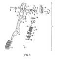
- FIG. 1is an exploded view of a pedal assembly according to an embodiment of the invention.
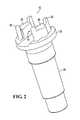
- FIG. 2is a perspective view of a pivot shaft and mounting cap according to an embodiment of the invention.
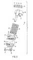
- FIG. 3is an exploded view of the hysteresis assembly illustrated in FIG. 1
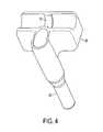
- FIG. 4illustrates the shaft and elastic member support illustrated in FIG. 3 .
- FIG. 5illustrates an exploded view of the hysteresis blocks illustrated in FIG. 3 .
- FIG. 6is a side view of a pedal assembly according to another embodiment of the present invention wherein a kickdown mechanism is included.
- FIG. 7is an exploded view of the kickdown mechanism illustrated in FIG. 6 .
- FIG. 8is a side view of the pedal assembly illustrated in FIG. 6 wherein the kickdown mechanism is engaged with the triggering mechanism.
- FIGS. 9-11illustrates graphs of the amount of force needed to cause the treadle in the pedal assembly illustrated in FIG. 6 to move specified distances when three different kickdown mechanisms are attached thereto.
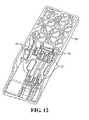
- FIG. 12is a perspective view of a bottom surface of a treadle according to an embodiment of the present invention.
- FIG. 13is a perspective view of the treadle illustrated in FIG. 12 wherein the treadle is attached to an end of a pedal arm according to an embodiment of the present invention.
- FIG. 14is a perspective view of an electronic controller and a pivot pin.
- FIG. 15is an exploded perspective view of the electronic controller, rotor, magnets, and pivot pin.
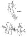
- FIG. 16is a perspective view of a pedal assembly incorporating the electronic controller.
- FIG. 17is an exploded perspective view of a bracket with a rotor and a pair of magnets disposed in spaced relationship between the electronic controller and the pivot pin.
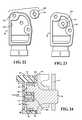
- FIG. 18is another cross-sectional view of the electronic controller taken along line 18 - 18 of FIG. 17 .
- FIG. 19Ais an exploded perspective view of the electronic controller.
- FIGS. 19B-19Dare exploded perspective views of the electronic controller during assembly of the controller.
- FIG. 19Eis a perspective view of the electronic controller.
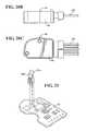
- FIG. 20Ais a front planar view of the electronic controller with a wiring harness mounted thereto.
- FIG. 20Bis a side planar view of the electronic controller with a wiring harness mounted thereto.
- FIG. 20Cis a back planar view of the electronic controller with a wiring harness mounted thereto.
- FIG. 21is a perspective view of a circuit board and a pair of hall effect sensors.
- FIG. 22is a planar view of a housing of the electronic controller before installation of a washer.
- FIG. 23is a planar view of the housing of the electronic controller after installation of the washer.
- FIG. 24is an inverted, enlarged and simplified cross-sectional view of a portion of the electronic controller as identified in FIG. 18 along with a portion of the pivot shaft disposed within a working chamber of the controller and installed on the mounting bracket.
- FIG. 1is an exploded view of a pedal assembly 10 according to an embodiment of the invention.
- the pedal assembly 10generally includes a mounting bracket 12 , a pedal arm 14 , a rotor assembly 16 , a sensor assembly 18 , a hysteresis assembly 20 , and a treadle 22 , or foot pedal 22 , attached to one end of pedal arm 14 .
- Pedal arm 14may be unitary or multi-piece, and converts translation of treadle 22 into rotation of rotor assembly 16 , which rotation is in turn sensed by sensor assembly 18 .
- Hysteresis assembly 20provides friction and a return force to pedal assembly 10 .
- sensor assembly 18 and hysteresis assembly 20are described in further detail below.
- Rotor assembly 16includes a shaft 24 , an end cap 26 , and magnetic assembly 28 .
- Magnetic assembly 28includes a shield 30 and magnets 32 .
- a mounting cap 34to which magnetic assembly 28 is attached, is provided on at least one end of shaft 24 adjacent sensor assembly 18 .
- mounting caps 34 and magnetic assemblies 28are provided at both ends of shaft 24 adjacent corresponding sensor assemblies 18 .
- Shaft 24 and end cap 26are secured together, for example by an appropriate fastener 36 , such as a bolt, a screw, or a pin.
- Shaft 24connects pedal arm 14 and mounting bracket 12 .
- Shaft 24is self-lubricating, such as a Teflon®.-coated shaft or a composite Delrin®. (Delrin®. 500CL) shaft.
- the use of a self-lubricating shaft 24substantially eliminates the need for discrete bearings supporting pedal arm 14 . That is, shaft 24 functions in place of a bearing, permitting simpler assembly of pedal assembly 10 and, in some embodiments, up to approximately fifteen million actuation cycles of pedal assembly 10 without failure.
- Mounting bracket 12includes integrally-formed, inwardly-protruding bearing surfaces 38 to support pivot shaft 24 and pedal arm 14 .
- Mounting bracket 12is a single component formed from a rigid material, for example steel, by an appropriate machining process, for example stamping. Bearing surfaces 38 are deep drawn into mounting bracket 12 . First, small holes are created on mounting bracket 12 at the desired locations of bearing surfaces 38 . Mounting bracket 12 is then drawn at these holes to the required depth and diameter for bearing surfaces 38 via a series of successive punches or a cone-shaped forming die.
- Mounting bracket 12 , pedal arm 14 , and rotor assembly 16are assembled by aligning apertures 40 in pedal arm 14 with bearing surfaces 38 on mounting bracket 12 . Shaft 24 is then inserted so as to pivotally connect pedal arm 14 and mounting bracket 12 .
- the interior profile of apertures 40complements the exterior profile of shaft 24 , thereby ensuring a proper, secure fit between these components and conversion of translation of treadle 22 into rotation of rotor assembly 16 . That is, pedal arm 14 does not rotate freely about shaft 24 ; rather, pedal arm 14 and shaft 24 rotate together upon bearing surfaces 38 .
- end cap 26is secured thereto in order to hold shaft 24 in place.
- magnetic assembly 28(shield 30 and magnets 32 ) is attached to shaft 24 at one end thereof on mounting cap 34 .
- Mounting cap 34is attached to shaft 24 so as to rotate with shaft 24 when treadle 22 is depressed or released.
- mounting cap 34is integrally formed with shaft 24 , though it is regarded as within the scope of the present invention to fixedly attach a separate mounting cap 34 to shaft 24 .
- FIG. 2is a perspective view of a pivot shaft 24 and mounting cap 34 according to an embodiment of the invention.
- mounting means 42 for magnetic assembly 28are integrally formed on mounting cap 34 , for example by molding mounting means 42 thereon.
- Mounting means 42generally include shield locating features, such as towers 44 , magnet locating features, such as slots 46 , and retention features, such as pins 48 .
- shield locating featuressuch as towers 44
- magnet locating featuressuch as slots 46
- retention featuressuch as pins 48
- a pair of shield locating towers 44project from mounting cap 34 , and shield 30 fits around towers 44 , as shown in FIG. 1 . That is, the exterior profile of towers 44 corresponds to the interior profile of shield 30 .
- a pair of magnet locating slotsis provided into which magnets 32 are fit.
- shield 30 and magnets 32are secured on mounting cap 32 and define an interior portion of the rotor 16 .
- shield 30 and magnets 32are secured via rivets driven into the retention features.
- pins 48are heat-staked to secure shield 30 and magnets 32 .
- shield 30 and magnets 32are secured through an overmolding process applied to mounting means 42 . In substantially all embodiments, however, the end result is a simplified unitary mounting for the rotating magnetic assembly 28 .
- pedal arm 14will convert this translation into rotation of shaft 24 , mounting cap 34 , and magnetic assembly 28 , which rotation is detected by sensor assembly 18 as further described below.
- hysteresis assembly 20provides hysteresis forces, including frictional forces and return forces, to pedal assembly 10 .
- hysteresis assembly 20provides a baseline force, herein referred to as an “initial displacement force” necessary to displace pedal arm 14 from its initial (i.e., idle) position.
- Hysteresis assembly 20also provides frictional forces designed to give a user the impression of a mechanical pedal assembly 10 , and a return force intended both to give the impression of a mechanical pedal and to bias pedal arm 14 towards its initial position.
- pedal arm 14will return to its initial, idle position, and will not stick in an open position.
- FIG. 3is an exploded view of the hysteresis assembly 20 illustrated in FIG. 1 .
- Hysteresis assembly 20generally includes an elastic member support 50 , a first hysteresis block 52 , a second hysteresis block 54 , and an elastic member, for example springs 56 , though other elastic members are regarded as within the scope of the invention.
- Springs 56connect elastic member support 50 and first hysteresis block 52 via seats 58 thereon.
- An alignment pin 60which, in certain embodiments of the present invention, is integrally formed with elastic member support 50 , aligns elastic member support 50 and second hysteresis block 54 .
- Hysteresis assembly 20also includes a shaft 64 to connect hysteresis assembly 20 to mounting bracket 12 , and a pin 66 to attach hysteresis assembly 20 to pedal arm 14 , both shown in FIG. 1 .
- pin 66includes ears 68 .
- shaft 60may include rings 70 to retain shaft 60 within mounting bracket 12 and to prevent sliding between shaft 60 and elastic member support 50 , which has a corresponding ridge 72 thereon, as illustrated in FIG. 4 , which illustrates the shaft 60 and elastic member support 50 illustrated in FIG. 3 .
- shaft 64pivotally attaches hysteresis assembly 20 to mounting bracket 12 at mounting holes 74 , with outermost rings 70 abutting the interior face of mounting bracket 12 .
- hysteresis assembly 20is installed underneath pedal arm 14 , between sidewalls 76 of mounting bracket 12 , such that displacement of pedal arm 14 also causes displacement of hysteresis assembly 20 , with hysteresis blocks 52 , 54 disposed between sidewalls 76 .
- pedal arm 14pivots about shaft 24
- hysteresis assembly 20pivots about shaft 64 . Therefore, as pedal arm 14 pivots, the distance between pin 66 and shaft 24 changes, displacing springs 56 .
- Springs 56are biased to return pedal arm 14 to its initial, idle position. As pedal arm 14 is displaced, via pressure applied to treadle 22 , springs 56 are stretched from equilibrium, generating a return force F r The return force will tend to restore springs 56 to their original length, which, in turn, will tend to urge pedal arm 14 back to its initial, idle position.
- the location of mounting holes 74 on mounting bracket 12is determined through an analysis of desired hysteresis characteristics.
- a desired initial displacement forceis selected.
- the “initial displacement force”is that force necessary to displace pedal arm 14 from its initial, idle position. This force may also be referred to as the “idle force.”
- the initial displacement forceis related to the spring rate k.
- a first surface 78 on first hysteresis block 52 and a second surface 80 on second hysteresis block 54interface at a slope a.
- pedal arm 14When pedal arm 14 is displaced, a component of the reaction force to springs 56 acts to slide hysteresis blocks 52 , 54 relative to each other along the sloped interface. In turn, this relative sliding motion causes at least one of frictional surfaces 82 , 84 to frictionally engage the interior surface of sidewalls 76 on mounting bracket 12 .
- hysteresis blocks 52 , 54Additional pressure on treadle 22 forces hysteresis blocks 52 , 54 further apart, increasing the normal force between frictional surfaces 82 , 84 and sidewalls 76 , and thus the frictional force acting to inhibit further depression of pedal arm 14 .
- the angle of the slope a between first and second surfaces 78 , 80is calculated to provide a desired frictional force profile as pedal arm 14 is displaced from its initial, idle position.
- the coefficient of friction between hysteresis blocks 52 , 54 along first and second surfaces 78 , 80 and the coefficient of friction between frictional surfaces 82 , 84 and sidewalls 76may be adjusted to achieve the desired frictional force profile.
- the frictional forces between hysteresis blocks 52 , 54 and sidewalls 76are directly related to the forces generated by springs 56 . That is, increased spring forces cause increased frictional forces and vice versa. This ensures that pedal assembly 10 complies with industry standards requiring return-to-idle when treadle 22 is released. Further, in the unlikely event a spring 56 fails, the return force F r would be halved, but so too would the frictional forces. Where frictional forces are independent of spring forces, it is possible for pedal arm 14 to “stick” in an open position when there is such a failure, as the return force may be insufficient to overcome the frictional force where the two are unrelated.
- a pedal assembly 10 with customized hysteresis forcescan be constructed using the principles elucidated above. For example, it is possible to alter the idle and Wide Open Throttle (WOT) pedal forces while maintaining the same relative relationship between the two. Alternatively, either force may be kept constant, and the difference between the two varied.
- WOTWide Open Throttle
- the end useridentifies the desired initial displacement force, the desired return force profile, and the desired frictional fore profile. Analyses are then conducted to determine the spring rate k of an elastic member 56 corresponding to the desired return force profile, the slope a of the interface between hysteresis blocks 52 , 54 corresponding to the desired frictional force profile, and the location of mounting holes 74 corresponding to the desired initial displacement force.
- Hysteresis assembly 20is then constructed using an elastic member 56 with spring rate k and a pair of adjacent hysteresis blocks 52 , 54 interfacing at the calculated slope a. Appropriately located mounting holes 74 are made on mounting bracket 12 , and an end of hysteresis assembly 20 is attached via shaft 64 .
- FIG. 1illustrates a dynamic system in the form of pedal assembly 10 .
- other dynamic systemsare also within the scope of the present invention.
- systems wherein it is desired to monitor the position of a moveable component and/or wherein it is desired to provide a hysteresis force to the moveable componentare also within the scope of the present invention.
- the pedal assembly 10 illustrated in FIG. 1includes a moveable component in the form of treadle 22 . As previously discussed and illustrated in FIG. 1 , treadle 22 is connected to pedal mounting bracket 12 via pedal arm 14 .
- end cap 26that is connected to a rotor shaft 24 using fastener 36 in order to form rotor assembly 16 .
- rotor assembly 16is connected to treadle 22 via pedal arm 14 and rotor assembly 16 is configured to rotate when treadle 22 moves between a first position (e.g., an idle position) and a second position (e.g., an open throttle position).
- FIG. 1also illustrates a pair of magnets 32 that each have an associated emitted magnetic field that, although not illustrated in FIG. 1 , emanates from each magnet 32 and grows gradually weaker at greater distances away from each magnet 32 .
- Each magnet 32is fixedly connected to rotor assembly 16 via the slots 46 and pins 48 illustrated in FIG. 2 that protrude from a proximate end of shaft 24 .
- sensor assembly 18Positioned adjacent to rotor assembly 16 , also on the proximate end thereof, is sensor assembly 18 .
- Sensor assembly 18is attached to mounting bracket 12 via the use of the two fasteners 86 illustrated on the right-hand side of FIG. 1 .
- sensor assembly 18is configured to detect the position of one or both of the magnets 32 as they rotate about the longitudinal axis of rotor shaft 24 when treadle 22 is depressed by a user of the pedal assembly 10 .
- sensor assembly 18detects the position of the magnets 32 using a Hall sensor, as will also be described below.
- FIG. 1also illustrates a magnetic shield 30 that is positioned adjacent to the towers 44 protruding from mounting cap 34 on rotor shaft 24 of rotor assembly 16 .
- magnetic shield 30substantially surrounds a portion of rotor assembly 16 that is adjacent to each of the magnets 32 .
- magnetic shield 30not only prevents exterior magnetic fluxes from interacting with either of the magnets 32 , but also acts as a flux concentrator that concentrates the magnetic fluxes from each of the magnets 32 within the interior of the magnetic shield 30 .
- FIG. 18is a cross-sectional view of the sensor assembly 18 .
- a working chamber 88is included with sensor assembly 18 and is configured to accommodate the insertion of one or more slots 46 and/or pins 48 from mounting cap 34 , the magnets 32 connected thereto, and the magnetic shield 30 substantially surrounding magnets 32 .
- a first sensor 91 Awhich can be a Hall sensor, is included in sensor assembly 18 and extends into the working chamber 88 in sensor assembly 18 .
- a second sensor 91 Bwhich can also be a Hall sensor, is included (see FIG. 21 ).
- the second sensor 91 Bis substantially identical to, electrically isolated from and slightly offset from the above-discussed first sensor 91 A.
- the use of two such sensors 91 A, 91 B positioned as described abovecan compensate for the fact that, in some embodiments of the present invention, a sensor cannot be placed at the exact center of rotation of rotor assembly 16 due to way that the sensor is packaged.
- a circuit board 92is connected to a set of wires 96 that extend outside of casing 94 and that, according to certain embodiments of the present invention, are connected to a microprocessor or controller (not shown).
- one or more of the components in sensor assembly 18are programmable. As such, the format or protocol of an output signal that travels through wires 96 and out of sensor assembly 18 may be switched without having to physically reconfigure any of the components in sensor assembly 18 .
- sensor assembly 18meets or exceeds Ingress Protection 67 (IP67) standards.
- IP67Ingress Protection 67
- casing 94is configured such that overall sensor assembly 18 is substantially water-tight and prevents dust from interfering with the electronics of sensor assembly 18 .
- FIG. 19Ais an exploded perspective view of the sensor assembly 18 .
- circuit board 92is illustrated as being enclosed between casing 94 and a casing cover 98 .
- additional magnetic shield 100within the casing 94 and cover 98 is an additional magnetic shield 100 .
- Additional magnetic shield 100supplements previously discussed magnetic shield 30 in that it prevents exterior magnetic fluxes parallel to the longitudinal axis 45 (see FIG. 1 ) of shaft 24 from entering sensor assembly 18 , whereas magnetic shield 30 protects the volume that it surrounds mainly from exterior magnetic fluxes transverse to the longitudinal axis of shaft 24 . Therefore, in conjunction with magnetic shield 30 additional magnetic shield 100 illustrated in FIGS. 22 and 23 protects magnets 32 and sensors 91 A, 91 B positioned between the magnets 32 from exterior magnetic fluxes both in the axial and radial directions relative to rotor assembly 16 .
- a commonly available circular metallic washer 101may be used as additional magnetic shield 100 .
- a method of monitoring a dynamic systemsuch as, for example, the above-discussed pedal assembly 10 .
- a componentsuch as, for example, treadle 22
- a second positione.g., an open throttle position where the vehicle is being accelerated.
- a rotorsuch as, for example, rotor assembly 16
- this rotating stepalso includes rotating an emitter (e.g., one of magnet 32 , which emits a magnetic field) that is fixedly connected to the rotor.
- the position of a first emitteris monitored with a sensor that is positioned adjacent to the rotor assembly. Since the sensors 91 A, 91 B on printed circuit board 92 are physically separated from magnets 32 , and since magnets 32 are fixedly linked to treadle 22 through pedal arm 14 and rotor assembly 16 , this monitoring step provides a noncontact (i.e., frictionless) method of monitoring the position of treadle 22 .
- the above methodallows for the programming of the first sensor 91 A to output a particular type of signal.
- one or both of the above-discussed Hall sensorsmay be programmed to output a continuous analog or a discrete digital signal.
- such programmabilityallows for changes to be made to the dynamic system without having to physically alter any of the components included therein.
- the above methodincludes monitoring the position of the first emitter with the second sensor 91 B, which is typically positioned adjacent to the rotor.
- the first signal from the first sensor 91 Ais processed (e.g., averaged) along with a second signal from the second sensor 91 B to determine the position of the first emitter.
- the use of two sensorsis particularly useful in embodiments of the present invention where the packaging of a sensor prevents the sensor from being positioned directly in the center of the rotor.
- One of the advantages of certain embodiments of the present inventionis that, particularly when the sensors 91 A, 91 B included in the dynamic system discussed above are Hall sensors, the entire system may be calibrated simply by taking a reading from sensor assembly 18 at a first position of treadle 12 (e.g., at idle) and at a second position of treadle 12 (e.g., at Wide Open Throttle (WOT)).
- WOTWide Open Throttle
- Such convenient and rapid calibrationis possible in dynamic systems according to certain embodiments of the present invention because the electronic sensors 91 A, 91 B used therein (e.g., Hall sensors) react substantially linearly in response to changes in the position of the emitters that they monitor.
- mechanical pedalsdo not necessarily react linearly and tend to “loosen” over time as the components thereof wear against each other. Thus, in some mechanical pedals, complex, time-consuming calibration procedures are typically performed on a regular basis.
- certain electronic pedal assembliesrestrict the sensors included therein to emitting an output signal having a value between a first threshold value and a second threshold value. Any circuitry that becomes apparent to one of skill in the art upon practicing the present invention may be used in order to implemented such restrictions.
- FIG. 8is a side view of a pedal assembly 102 according to another embodiment of the present invention.
- pedal assembly 102includes a treadle 22 that is connected to a mounting bracket 12 via a pedal arm 14 .
- pedal arm 14rotates relative to bearing surfaces 38 on mounting bracket 12 (see FIG. 1 ).
- pedal assembly 102includes a resistance mechanism, referred to herein as a kickdown mechanism 104 , that is attached to pedal arm 14 of pedal assembly 102 .
- a kickdown mechanism 104that is attached to pedal arm 14 of pedal assembly 102 .
- a triggering mechanism 106that, in the embodiment of the present invention illustrated in FIG. 8 , takes the form of a flat plate attached to mounting bracket 12 .
- alternate geometries for triggering mechanism 106are also within the scope of the present invention.
- FIG. 9is an exploded view of kickdown mechanism 104 illustrated in FIG. 8 .
- kickdown mechanism 104includes a casing 108 configured to be attached to a pedal assembly.
- casing 108 of kickdown mechanism 104is attached to pedal arm of pedal assembly 10 between treadle 22 and bearing surface 33 .
- fixed magnetic component 110Inside casing 108 is a fixed magnetic component 110 .
- the proximate and distal ends of fixed magnetic component 110slide into slots 112 located in a lower portion of casing 108 . As such, once fixed magnetic component 110 is inserted into casing 108 , it is no longer free to move.
- moveable magnetic component 114Also inside casing 108 is a moveable magnetic component 114 .
- the length of moveable magnetic component 114is typically slightly less than the distance between the two interior sidewalls 116 of casing 108 . Therefore, moveable magnetic component 114 is configured to slide up and down within casing 108 .
- contact mechanism 118Positioned adjacent to moveable magnetic component 114 is a contact mechanism 118 that, in FIG. 9 , takes the form of a plunger. As will be discussed below with reference to FIG. 10 , contact mechanism 118 is configured to contact triggering mechanism 106 when treadle 22 in pedal assembly 10 is depressed beyond a predetermined position.
- contact mechanism 118extends through a hole 120 in fixed magnetic component 110 .
- contact mechanism 118does not travel through any portion of fixed magnetic component 110 .
- a portion of contact mechanism 118may travel next to fixed magnetic component 110 .
- an elastic member 122that is substantially enclosed within casing 108 , particularly when cover 124 is attached to casing 108 .
- Elastic member 122which is illustrated in FIG. 9 as a spring, is positioned between moveable magnetic component 114 and an upper interior side wall 126 of casing 108 when all of the components of kickdown mechanism 104 are assembled together.
- one or both of the ends of elastic member 122are physically connected to casing 108 and/or moveable magnetic component 114 .
- the elastic member 122is held in compression between moveable magnetic component 114 and upper interior side wall 126 and/or is confined by the interior sidewalls 116 and therefore remains unattached at either end.
- a method of altering a force needed to depress a pedal componente.g., a treadle
- a pedal componente.g., a treadle
- FIG. 8wherein kickdown mechanism 104 is offset from triggering mechanism 106
- FIG. 10which is a side view of pedal assembly 102 wherein kickdown mechanism 104 is engaged with triggering mechanism 106 .
- the pedal componentis treadle 22 and the path is the one along which treadle 22 travels as kickdown mechanism 104 travels between the un-engaged position relative to triggering mechanism 106 illustrated in FIG. 8 and the engaged position illustrated in FIG. 10 .
- the above-mentioned methodincludes providing a first resistance component to a pedal component as the pedal component travels along a first portion of a path.
- this stepincludes providing a first level of resistance to a user's foot as the user depresses treadle 22 from the position illustrated in FIG. 8 to a position where contact mechanism 118 just comes into contact with triggering mechanism 106 .
- This first level of resistancemay be provided, for example, using hysteresis assembly 20 in the manner discussed above with reference to pedal assembly 10 .
- the above-discussed kickdown mechanismhas a variety of uses.
- the higher level of force needed to depress the treadlefurther can be used to alert operators of vehicles that they may be operating the vehicle unsafely.
- a kickdown mechanismmay be used to alert drivers of automobiles that they are speeding.
- kickdown mechanismsmay be used to optimize fuel efficiency of a vehicle. More specifically, the force exerted by the kickdown mechanism can be use to alert a user that the vehicle is being operated outside of the most fuel-efficient range of parameters.
- the methodalso includes supplementing the first resistance component with a second resistance component as the pedal component travels along a second portion of the path.
- contact mechanism 118When implementing this step using pedal assembly 102 , contact mechanism 118 , fixed magnetic component 110 (which is located inside of casing 108 shown in FIG. 8 ) and moveable magnetic component 114 (which is also located inside of casing 108 ) are used. More specifically, as treadle 22 keeps moving toward the position illustrated in FIG. 10 after contact mechanism 118 initially comes into contact with triggering mechanism 106 , contact mechanism 118 will begin applying force to moveable magnetic component 114 . In turn, since moveable magnetic component 114 is magnetically attracted to fixed magnetic component 110 moveable magnetic component 114 will resist being moved. As a result, the attractive magnetic force between moveable magnetic component 114 and fixed magnetic component 110 will provide a second resistance component of force that will have to be overcome as the motion of treadle 22 continues.
- contact mechanism 118(illustrated in FIG. 9 ) is driven to positions that initially force magnetic components 110 and 114 to lose direct contact with each other and that subsequently move magnetic components 110 and 114 further away from each other, the attractive magnetic force between the components diminishes.
- certain embodiments of the above-discussed methodinclude initially increasing and subsequently decreasing the second resistance component as the pedal component travels along the second portion of the path.
- the methodalso includes further supplementing the first resistance component and the second resistance component with a third resistance component as the pedal component travels along a third portion of the path.
- elastic member 122i.e., a spring
- treadle 22continues to move and continues to force more and more of contact mechanism 118 into casing 108
- magnetic component 114will compress elastic member 122 more and more.
- elastic member 122will exert more and more mechanical spring force to resist motion of magnetic component 114 and, in turn, contact mechanism 118 and treadle 22 .
- FIGS. 11-13each illustrate a graph of the amount of force (F) needed to cause treadle 22 in pedal assembly 102 to move specified distances (s) when three different kickdown mechanisms are attached thereto.
- Fthe amount of force
- FIG. 11only magnetic components 110 and 114 are included within casing 108 .
- the amount of force needed to move treadle 22increases sharply when the movement of contact mechanism 118 is initially impeded by the magnetic components 110 and 114 . However, once the magnetic components 110 and 114 separate and move farther and farther apart, their influence on contact mechanism 118 diminishes.
- the graph in FIG. 12is generated using a kickdown mechanism that includes only elastic member 122 .
- a kickdown mechanismthat includes only elastic member 122 .
- the graph in FIG. 13is generated using magnetic components 110 and 114 and elastic member 122 .
- a positionis reached where the magnetic component of resistive force produced by magnetic components 110 and 114 has to be overcome for treadle 22 to continue moving.
- the mechanical component of resistive forcehas to be overcome for treadle 22 to continue moving.
- FIG. 14is a perspective view of a bottom surface of a treadle 128 according to an embodiment of the present invention.
- FIG. 15is a perspective view of treadle 128 wherein treadle 128 is attached to an end of a pedal arm 130 according to an embodiment of the present invention.
- treadle 128includes four flexible protrusions 132 and, as illustrated in FIG. 15 , pedal arm 130 includes a plurality of engaging surfaces 134 configured to accommodate engagement of flexible protrusions 132 therewith.
- protrusions 132are each polymeric and each include a tab 133 at or near the free end thereof.
- the engaging surfaces 134include holes, slots, depressions or other surface features into which tabs 133 may be inserted in order to secure treadle 128 to pedal arm 130 .
- protrusions 132are configured to incur plastic deformation upon detachment of treadle 128 from pedal arm 130 .
- protrusions 132are configured to fracture upon detachment of treadle 128 from pedal arm 130 . Either way, once treadle 128 has been detached, it cannot be reattached to pedal arm 130 . Thus, a disincentive is provided to using potentially unsafe refurbished treadles instead of replacing a damaged treadle with a new one.
- Both sets of engaging surfaces 134 illustrated in FIG. 15are positioned substantially opposite each other. Also, both sets of protrusions 132 are positioned substantially parallel to each other. However, even a single protrusion and engaging surface combination may be used to secure a treadle to a pedal arm, and more than the four such combinations illustrated in FIG. 15 may be used. Also, the positioning of protrusions 132 relative to each other and of engaging surfaces 134 relative to each other will depend upon the geometries of the components in the pedal system that includes the treadle.
- a method of assembling a pedaltypically includes elastically deflecting a first protrusion of a treadle a first amount.
- one of the protrusions 132may be deflected a small amount that will neither cause plastically deformation nor fracture thereof.
- a protrusion 132may be pressed against the edge of an engaging surface 134 on pedal arm 130 until the protrusion 132 deflects just enough to allow the tab 133 thereon to slide relative to the engaging surface 134 .
- the methodalso includes positioning the first protrusion adjacent to a first engaging surface on a pedal arm that is pivotally connected to a bracket.
- treadle 128When implementing this step using treadle 128 , the above-discussed tab 133 is slid relative to the engaging surface 134 until the tab 133 is aligned with a hole, slot or depression on the engaging surface 134 .
- the methodincludes engaging the first engaging surface with the first protrusion by reducing the first amount of deflection in the first protrusion.
- the methodalso includes elastically deflecting a second protrusion of the treadle a second amount, positioning the second protrusion adjacent to a second engaging surface on the pedal arm, wherein the second engaging surface is substantially parallel to the first engaging surface, and engaging the second engaging surface with the second protrusion by reducing the second amount of deflection in the second protrusion.
- Each of these steps relative to the second protrusionmay be performed in a manner analogous to the corresponding steps relative to the first protrusion and, as will be appreciated by one of skill in the art upon practicing the present invention, the use of multiple protrusions and engaging surfaces more securely attaches the treadle to the pedal arm.
- the above-discussed methodalso includes either plastically deforming the first protrusion upon disengagement of the first protrusion and the first engaging surface or fracturing the first protrusion upon disengagement of the first protrusion and the first engaging surface. Either way, the above-discussed used of potentially unsafe refurbished treadles is substantially prevented.
- the above-discussed tabs 133may be configured to engage with the above-discussed engaging surfaces 134 in such a manner no convenient method or tooling exists for extricating the tabs 133 from the engaging surfaces 134 .
- the sensor assembly or electronic controller 18can be associated with any suitable control device to perform a variety of functions.
- the electronic controller 18could be part of a vehicle shifter assembly, hand throttle control, pedal assembly 10 or any other suitable position sensing device.
- the electronic controller 18is mounted directly to a mounting bracket 12 of a pedal assembly 10 .
- the pedal assembly 10is configured as a suspended pedal having a steel mounting bracket 12 .
- the pedal assembly 10 shownis merely illustrative of a suitable design.
- a floor mounted pedal assembly or a pedal assembly that is adjustable in fore and aft directionsare contemplated as other suitable alternatives.
- the implementation of the electronic controller 18is in no way limited to pedal assemblies and, as discussed above, the electronic controller 18 could be associated with any suitable position sensing device.
- the mounting bracket 12supports a shaft or pivot pin 24 , which in turn supports a pedal arm 14 .
- the electronic controller 18is disposed about a first end 136 of the pivot pin 24 .
- the pivot pin 24is Teflon coated such that no additional bearing material is needed.
- the pin 24includes first 136 and second 138 ends with a cap 26 mounted to the second end 138 by a cap screw 36 .
- the first end 136 of the pivot pin 24extends to an opposing side of the mounting bracket 12 and into the electronic controller 18 .
- the first end 136includes the mounting cap or support base 34 and a pair of projecting towers 44 .
- a shield or rotor 30is disposed about the towers 44 and a pair of magnets 32 are inserted within indentations in the towers 44 .
- the rotor 30 and magnets 32 installed on the pivot pin 24provide a magnetic signal for the electronic controller 18 .
- tabs on the towers 44 of the pivot pin 24are heat-staked to retain these components in position.
- This design of the first end 136 of the pivot pin 24creates a simplified unitary mounting for the rotating sensing components of the electronic controller 18 .
- the electronic controller 18includes a casing or plastic housing 94 defining an inner cavity 140 and a working chamber 88 .
- the casing 94has exterior walls with an interior surface defining the inner cavity 140 within the casing 94 and the exterior walls have an exterior surface outside of the inner cavity 140 defining the working chamber 88 .
- a pair of compression tubes 142preferably formed of metal, extend through apertures in the housing 94 to prevent damage to the housing 94 when the housing 94 is mounted to the bracket 12 of the pedal assembly 10 .
- a fastener 86 of any suitable designpasses through the compression tubes 142 to mount the housing 94 to the control device, such as the pedal assembly 10 .
- the working chamber 88has an interior wall that is preferably configured as a smooth concentric surface.
- the first end 136 of the pivot pin 24which includes the rotor 30 and magnets 32 , is disposed within the working chamber 88 once the electronic controller 18 is mounted to the pivot pin 24 of the pedal assembly 10 (see FIG. 24 ).
- a protrusion 144extends from the inner cavity 140 into the working chamber 88 .
- the protrusion 144is hollow and defines a second inner cavity within the controller 18 .
- the protrusion 144is preferably disposed centrally within the working chamber 88 and is positioned between the magnets 32 when the controller 18 is mounted to the pivot pin 24 .
- a circuit board 92is mounted within the inner cavity 140 of the housing 94 .
- the circuit board 92may be of any suitable design and may include any suitable configuration of electronics as is desired.
- one or more hall effect sensors 91 A, 91 Bextend from the circuit board 92 and are disposed within the second inner cavity of the protrusion 144 .
- the hall effect sensors 91 A, 91 Bwhich are disposed within the protrusion 144 , are placed in close proximity to the magnets 32 .
- the close proximity of the sensors 91 A, 91 B and magnets 32provides excellent correlation between sensor output voltages and significantly decreases non-linearity impacts of the sensor 91 A, 91 B on the outputs.
- the positioning of the sensors 91 A, 91 B within the protrusion 144also automatically aligns the hall effect sensors 91 A, 91 B between the magnets 32 to ensure proper operation of the electronic controller 18 .
- the sensors 91 A, 91 B and magnets 32are close in proximity, the sensor 91 A, 91 B and rotor 30 /magnets 32 are completely separated and isolated from one another.
- the hall effect sensors 91 A, 91 Bmay be programmed differently to recognize different dynamics or conditions. Alternatively, the hall effect sensors 91 A, 91 B may have common programming to provide a level of redundancy. As an example, one of the hall effect sensors 91 A, 91 B could be programmed to recognize a specific position of the magnets 32 or the pivot pin 24 to control an idle validation switch.
- the idle validation switchis preferably a solid state switch, which is capable of handling higher DC voltage than mechanical switches.
- the idle switchis protected against overcurrent through a polymer type resetable fuse. This fuse prevents switch damage caused by incorrect installation or accidental application of excessive current during an assembly process.
- the electronic controller 18has the ability to accurately program and change a switching position to any required position of the magnets 32 .
- one or more layers of protective material 148are disposed on the circuit board 92 to protect the soldered components of the circuit board 92 .
- a layer of sealing material 150is disposed about a periphery of the housing 94 to provide a seal to the housing 94 .
- a casing cover or shield 98is disposed over the inner cavities of the housing 94 to close the cavities of the housing 94 .
- the shield 98is formed of a ferromagnetic material to prevent external magnetic fields from influencing sensor output.
- a washer 101which is also formed of a ferromagnetic material, may be installed within the inner cavity 140 about the second inner cavity of the protrusion 140 . The washer 101 would also operate to prevent external magnetic fields from influencing sensor output.
- the electronic controller 18can include a suitable wiring harness 152 for connecting the electronic controller 18 to a desired component of the vehicle.
- the electronic controller 18could include an integrated connector.
- the first end 136includes the support base 34 and the pair of projecting towers 44 with each of the towers 44 having a pair of tabs.
- a coil rotor 30is first disposed about the towers 44 and a pair of magnets 32 are inserted within indentations in the towers 44 .
- the coil rotor 30 and magnets 32operate in conjunction with single or multiple hall effect sensors 91 A, 91 B to provide the desired sensing of the rotation of the pivot pin 24 .
- the tabs on the first end 136 of the pivot pin 24are heat-staked to retain these components in position.
- This design of the first end 136 of the pivot pin 24creates a simplified unitary mounting for the rotating sensing components of the electronic controller 18 .
- the coil rotor 30 and magnets 32operate in conjunction with the hall effect sensor 91 A, 91 B, which is shown schematically in FIG. 24 , to provide the desired sensing of the rotation of the pivot pin 24 .
Landscapes
- Engineering & Computer Science (AREA)
- Physics & Mathematics (AREA)
- General Physics & Mathematics (AREA)
- Automation & Control Theory (AREA)
- Chemical & Material Sciences (AREA)
- Combustion & Propulsion (AREA)
- Transportation (AREA)
- Mechanical Engineering (AREA)
- Mechanical Control Devices (AREA)
- Auxiliary Drives, Propulsion Controls, And Safety Devices (AREA)
- Control Of Throttle Valves Provided In The Intake System Or In The Exhaust System (AREA)
Abstract
Description
Claims (14)
Priority Applications (1)
| Application Number | Priority Date | Filing Date | Title |
|---|---|---|---|
| US11/333,530US8240230B2 (en) | 2005-01-18 | 2006-01-18 | Pedal sensor and method |
Applications Claiming Priority (4)
| Application Number | Priority Date | Filing Date | Title |
|---|---|---|---|
| US64488405P | 2005-01-18 | 2005-01-18 | |
| US68664205P | 2005-06-02 | 2005-06-02 | |
| US69384505P | 2005-06-24 | 2005-06-24 | |
| US11/333,530US8240230B2 (en) | 2005-01-18 | 2006-01-18 | Pedal sensor and method |
Publications (2)
| Publication Number | Publication Date |
|---|---|
| US20060169093A1 US20060169093A1 (en) | 2006-08-03 |
| US8240230B2true US8240230B2 (en) | 2012-08-14 |
Family
ID=36692762
Family Applications (4)
| Application Number | Title | Priority Date | Filing Date |
|---|---|---|---|
| US11/333,529AbandonedUS20060179971A1 (en) | 2005-01-18 | 2006-01-18 | Pedal attachment apparatus and method |
| US11/333,545Active2028-10-02US8266982B2 (en) | 2005-01-18 | 2006-01-18 | Method and apparatus for pedal hysteresis |
| US11/333,531AbandonedUS20060169097A1 (en) | 2005-01-18 | 2006-01-18 | Pedal kickdown mechanism and treadle attachment mechanism |
| US11/333,530Active2029-10-26US8240230B2 (en) | 2005-01-18 | 2006-01-18 | Pedal sensor and method |
Family Applications Before (3)
| Application Number | Title | Priority Date | Filing Date |
|---|---|---|---|
| US11/333,529AbandonedUS20060179971A1 (en) | 2005-01-18 | 2006-01-18 | Pedal attachment apparatus and method |
| US11/333,545Active2028-10-02US8266982B2 (en) | 2005-01-18 | 2006-01-18 | Method and apparatus for pedal hysteresis |
| US11/333,531AbandonedUS20060169097A1 (en) | 2005-01-18 | 2006-01-18 | Pedal kickdown mechanism and treadle attachment mechanism |
Country Status (5)
| Country | Link |
|---|---|
| US (4) | US20060179971A1 (en) |
| EP (4) | EP1860518A3 (en) |
| AT (1) | ATE520957T1 (en) |
| PL (1) | PL1868058T3 (en) |
| WO (1) | WO2006078579A2 (en) |
Cited By (15)
| Publication number | Priority date | Publication date | Assignee | Title |
|---|---|---|---|---|
| US20120272785A1 (en)* | 2009-11-04 | 2012-11-01 | Robert Bosch Gmbh | Pedal Travel Transducer and Pedal Unit |
| US20140251065A1 (en)* | 2013-03-06 | 2014-09-11 | Paccar Inc. | Clutch brake warning indicator |
| US20140331813A1 (en)* | 2013-05-07 | 2014-11-13 | Kia Motors Corp. | Active control method of pedal effort for accelerator |
| US20150253803A1 (en)* | 2012-12-02 | 2015-09-10 | Carl Johan Walter WESCHKE | Rotation detection device and a vehicle pedal comprising such a device |
| US20160067588A1 (en)* | 2014-09-05 | 2016-03-10 | Dynamic Labs, Llc | Motorized vehicle |
| US10112484B2 (en) | 2014-07-30 | 2018-10-30 | Orscheln Products L.L.C. | Throttle pedal |
| US10146246B2 (en) | 2016-08-24 | 2018-12-04 | Cts Corporation | Rotor for vehicle pedal with contacting sensor |
| US10195938B2 (en)* | 2015-07-21 | 2019-02-05 | Ksr Ip Holdings Llc | Clutch sensor with wake up switch |
| US10296037B2 (en) | 2015-09-18 | 2019-05-21 | Kongsberg Power Products Systems I, Inc. | Pedal assembly with identical first and second housing components |
| US10551866B2 (en) | 2015-09-18 | 2020-02-04 | Kongsberg Power Products Systems I, Inc. | Pedal assembly with debris filtering mechanism |
| US11353911B2 (en) | 2020-01-23 | 2022-06-07 | Ventra Group Co. | Pedal assembly |
| US20230059359A1 (en)* | 2021-08-18 | 2023-02-23 | Hyundai Motor Company | Organ-type electronic pedal device |
| US11619962B2 (en) | 2020-01-30 | 2023-04-04 | Ventra Group Co. | Retainer for brake booster rod |
| US20250181102A1 (en)* | 2023-11-30 | 2025-06-05 | Cts Corporation | Vehicular pedal assembly |
| US12384334B2 (en) | 2023-11-30 | 2025-08-12 | Cts Corporation | Vehicular pedal assembly |
Families Citing this family (41)
| Publication number | Priority date | Publication date | Assignee | Title |
|---|---|---|---|---|
| US7823480B2 (en)* | 2003-07-03 | 2010-11-02 | Ksr Technologies Co. | Support bracket with an integrated switch for a pedal assembly |
| US20050097980A1 (en)* | 2003-11-07 | 2005-05-12 | Brad Menzies | Kickdown mechanism |
| KR100589190B1 (en)* | 2004-06-25 | 2006-06-12 | 현대자동차주식회사 | Electronic pedals |
| EP1860518A3 (en)* | 2005-01-18 | 2010-09-08 | Teleflex Incorporated | Pedal assembly and method |
| DE102005015141A1 (en)* | 2005-03-31 | 2006-10-05 | Robert Bosch Gmbh | Position sensor system |
| US7246598B2 (en)* | 2005-11-02 | 2007-07-24 | Keihin Corporation | Accelerator pedal device |
| DE102006001242A1 (en)* | 2006-01-10 | 2007-07-12 | Tyco Electronics Amp Gmbh | Non-contact position sensor with reversible self-adjustment |
| US20070193400A1 (en)* | 2006-01-27 | 2007-08-23 | Kline Scott A | Clutch pedal mechanism with variable resistive force |
| US20070193401A1 (en)* | 2006-02-02 | 2007-08-23 | Cts Corporation | Accelerator pedal for a vehicle |
| ITTO20060156U1 (en) | 2006-10-19 | 2008-04-20 | I M A M S P A | MOUNTING DEVICE FOR A ROTATION SENSOR AT A CONTROL PEDAL OF A MOTOR VEHICLE. |
| US8083248B1 (en)* | 2007-04-03 | 2011-12-27 | Gulley Thomas D | Extension bracket |
| CN101681181A (en)* | 2007-05-09 | 2010-03-24 | Cts公司 | Accelerator pedal for a vehicle |
| KR100877200B1 (en)* | 2007-09-11 | 2009-01-07 | 주식회사 동희산업 | Kickdown switch on accelerator pedal |
| ITTO20070878A1 (en)* | 2007-12-05 | 2009-06-06 | Sistemi Comandi Meccanici S C | CONTROL PEDAL FOR THE CONTROL OF AN ACTUATOR OF A MOTOR VEHICLE, EQUIPPED WITH A ROTATION PIN WITH FIXING OF THE ELECTRONIC SENSOR. |
| US20120061996A1 (en)* | 2008-04-01 | 2012-03-15 | Gulley Thomas D | Extension bracket |
| US20110100153A1 (en)* | 2008-05-08 | 2011-05-05 | Murray Kaijala | Accelerator Pedal Assembly |
| KR100931145B1 (en)* | 2008-07-04 | 2009-12-10 | 현대자동차주식회사 | Control mechanism of the adjustable kick down switch |
| WO2010036674A1 (en)* | 2008-09-26 | 2010-04-01 | Cts Corporation | Accelerator pedal for a vehicle |
| GB2465761A (en)* | 2008-11-27 | 2010-06-02 | Gm Global Tech Operations Inc | A clutch pedal with a spring having an adjustable spring characteristic |
| EP2239187B1 (en)* | 2009-04-07 | 2012-11-14 | BT Products AB | Industrial truck with system for detection of the position of a pivotal platform |
| JP5371147B2 (en) | 2009-05-20 | 2013-12-18 | 株式会社ミクニ | Accelerator pedal device |
| DE112010003597T5 (en)* | 2009-09-09 | 2012-11-22 | Cts Corp. | Resistance mechanism for a pedal group |
| DE102009042402A1 (en)* | 2009-09-21 | 2011-03-24 | Volkswagen Ag | Pedal arrangement for vehicle, particularly motor vehicle, has bearing block and pedal lever which is pivotally supported between side cheeks of bearing block by bearing axis |
| KR101459427B1 (en) | 2009-12-03 | 2014-11-21 | 현대자동차 주식회사 | A kick down switch device in vehicle's accelerator pedal |
| JP5282919B2 (en)* | 2011-05-25 | 2013-09-04 | 株式会社デンソー | Accelerator device |
| DE112012004175T5 (en) | 2011-10-07 | 2014-07-24 | Cts Corporation | Vehicle pedal arrangement with hysteresis arrangement |
| US10013016B2 (en) | 2012-03-14 | 2018-07-03 | Ksr Ip Holdings Llc. | Method and instruction for attachment of ETC pedal to bracket |
| DE102012220383A1 (en)* | 2012-11-08 | 2014-05-08 | Robert Bosch Gmbh | Active accelerator pedal |
| EP2987046B1 (en)* | 2013-04-15 | 2017-06-14 | Kongsberg Power Products Systems Ltd. | Bidirectional pedal assembly |
| KR101801536B1 (en)* | 2013-05-13 | 2017-11-27 | 주식회사 만도 | Installation structure for pedal stroke sensor |
| CN103318150B (en)* | 2013-06-03 | 2015-12-23 | 东风汽车公司 | A kind of Novel electronic brake pedal and using method thereof |
| EP2874041B1 (en)* | 2013-11-19 | 2017-05-10 | MAKERSAN Makina Otomotiv Sanayi Ticaret Ltd. Sti. | A pedal mechanism and a low cost production method of a bracket therefor |
| DE102014102758A1 (en) | 2014-03-03 | 2015-09-03 | Hella Kgaa Hueck & Co. | Pedal sensors |
| US10353422B2 (en) | 2015-06-23 | 2019-07-16 | Kongsberg Power Products Systems I, Inc. | Bidirectional pedal assembly |
| US10036658B2 (en)* | 2015-08-21 | 2018-07-31 | Te Connectivity Corporation | Sensor assembly |
| FR3052886B1 (en)* | 2016-06-16 | 2019-06-21 | Peugeot Citroen Automobiles Sa | PEDAL SYSTEM FOR CONTROLLING AN AUTOMATED ACTUATOR COMPRISING A HYSTERESIS |
| CN106014654A (en)* | 2016-08-02 | 2016-10-12 | 洛阳市黄河软轴控制器股份有限公司 | Electronic manual accelerator controller |
| CN106050438A (en)* | 2016-08-02 | 2016-10-26 | 洛阳市黄河软轴控制器股份有限公司 | Controller for electronic foot accelerator |
| WO2020227380A1 (en) | 2019-05-09 | 2020-11-12 | Cts Corporation | Brake pedal assembly and pedal resistance force member with force and position sensors |
| CN116917172A (en) | 2021-01-13 | 2023-10-20 | Cts公司 | Vehicle pedal resistance damping assembly |
| US12090980B2 (en) | 2022-09-06 | 2024-09-17 | Cts Corporation | Brake pedal emulator |
Citations (224)
| Publication number | Priority date | Publication date | Assignee | Title |
|---|---|---|---|---|
| US3554096A (en) | 1968-12-09 | 1971-01-12 | Xomox Corp | Vane-type actuator |
| US3576379A (en) | 1969-01-27 | 1971-04-27 | James A Parise | Portable low-pressure direct current pump |
| US3946691A (en) | 1973-10-17 | 1976-03-30 | Metal Marine Pilot, Inc. | Autopilot employing improved hall-effect direction sensor |
| US4011469A (en) | 1973-07-09 | 1977-03-08 | U.S. Philips Corporation | Hall effect-switching device |
| US4060144A (en) | 1976-01-12 | 1977-11-29 | Pyott-Boone Machinery Corporation | Combined accelerator and brake assembly |
| US4086533A (en) | 1975-11-12 | 1978-04-25 | U.S. Philips Corporation | Hall effect apparatus for determining the angular position of a rotating part |
| US4112885A (en) | 1975-05-23 | 1978-09-12 | Nippon Soken, Inc. | Throttle valve control system for an internal combustion engine |
| US4134030A (en) | 1977-01-03 | 1979-01-09 | Motorola, Inc. | Hall-effect integrated circuit switch |
| US4133407A (en) | 1976-11-11 | 1979-01-09 | Schantz Spencer C | Vehicle speed controller |
| US4138979A (en) | 1977-09-29 | 1979-02-13 | The Bendix Corporation | Fuel demand engine control system |
| US4204158A (en) | 1977-04-20 | 1980-05-20 | U.S. Philips Corporation | Hall effect position detector using a single permanent magnet |
| US4218659A (en) | 1978-01-27 | 1980-08-19 | Hitachi, Ltd. | Amplifier circuit for a hall-effect head |
| US4228878A (en) | 1977-03-04 | 1980-10-21 | Kabushiki Kaisha Komatsu Seisakusho | Control device for controlling accelerator and brake switches |
| US4275291A (en) | 1978-08-21 | 1981-06-23 | Wilgood Corporation | Rotation sensor |
| US4278059A (en) | 1978-09-11 | 1981-07-14 | Vdo Adolf Schindling Ag | Device for the control of the traveling speed of a motor vehicle |
| US4313515A (en) | 1978-12-27 | 1982-02-02 | Vdo Adolf Schindling Ag | Device for the control of the traveling speed of a motor vehicle |
| US4313408A (en) | 1977-03-30 | 1982-02-02 | Vdo Adolf Schindling Ag | Device for the control of the traveling speed of a motor vehicle |
| US4319658A (en) | 1977-12-07 | 1982-03-16 | Vdo Adolf Schindling Ag | Device for the control of the traveling speed of a motor vehicle |
| US4336857A (en) | 1979-04-04 | 1982-06-29 | Associated Engineering Limited | Vehicle speed-control system and actuator device |
| US4354071A (en) | 1980-05-15 | 1982-10-12 | Sybron Corporation | Plural pedal foot control |
| US4364022A (en) | 1981-09-11 | 1982-12-14 | Towmotor Corporation | Magnetic control pedal apparatus |
| US4373486A (en) | 1981-01-09 | 1983-02-15 | Magnavox Government And Industrial Electronics Company | Rotational position and velocity sensing apparatus |
| US4380799A (en) | 1979-06-29 | 1983-04-19 | Regie Nationale Des Usines Renault | Speed control for an automobile |
| US4438398A (en) | 1980-10-22 | 1984-03-20 | Sony Corporation | Position detecting signal generator |
| US4493303A (en) | 1983-04-04 | 1985-01-15 | Mack Trucks, Inc. | Engine control |
| US4505151A (en) | 1982-04-23 | 1985-03-19 | Vdo Adolf Schindling Ag | Position indicator which can be coupled to a gas pedal in order to control the speed of travel of an automotive vehicle |
| US4510906A (en) | 1982-09-17 | 1985-04-16 | Wabco Westinghouse Fahrzeugbremsen Gmbh | Accelerator pedal mechanism for optimizing fuel economy |
| US4519361A (en) | 1983-04-11 | 1985-05-28 | Nissan Motor Company, Limited | Throttle control system for automotive vehicle |
| US4519360A (en) | 1983-04-11 | 1985-05-28 | Nissan Motor Company, Limited | Accelerator pedal control system for automotive vehicle |
| US4531431A (en) | 1981-12-24 | 1985-07-30 | M.A.N.-Maschinenfabrik Augsburg Nurnberg | Method and device for controlling a motor vehicle power unit |
| US4541378A (en) | 1983-09-12 | 1985-09-17 | Aisan Kogyo Kabushiki Kaisha | Throttle control device for internal combustion engine |
| US4552116A (en) | 1983-08-26 | 1985-11-12 | Hitachi, Ltd. | Engine control apparatus |
| US4566418A (en) | 1983-08-30 | 1986-01-28 | Mikuni Kogyo Kabushiki Kaisha | Electronically controlled internal combustion engine provided with an accelerator position sensor |
| US4612615A (en) | 1983-04-11 | 1986-09-16 | Nissan Motor Company, Limited | Throttle control system for automotive vehicle |
| US4621525A (en) | 1984-12-17 | 1986-11-11 | Ford Motor Company | Accelerator pedal actuator system for automatic driving system |
| US4675585A (en) | 1984-09-07 | 1987-06-23 | Outboard Marine Corporation | Electric vehicle speed control |
| US4695819A (en) | 1985-03-21 | 1987-09-22 | Lucas Industries Public Limited Company | Pedal device |
| US4720792A (en) | 1984-11-26 | 1988-01-19 | Fujitsu Limited | Method and apparatus for controlling operation of a throttle |
| US4727838A (en) | 1986-05-09 | 1988-03-01 | Hitachi, Ltd. | Apparatus for controlling internal combustion engine |
| US4763264A (en) | 1984-09-29 | 1988-08-09 | Mazda Motor Corporation | Engine control system |
| US4785691A (en) | 1986-03-22 | 1988-11-22 | Daimler-Benz Aktiengesellschaft | Device for regulating an internal combustion engine in a motor vehicle |
| US4833947A (en) | 1987-08-21 | 1989-05-30 | Toyota Jidosha Kabushiki Kaisha | Diagnostic system for a kickdown switch in an automotive vehicle |
| US4843555A (en) | 1984-12-28 | 1989-06-27 | Isuzu Motors Limited | Signal processing system for vehicular acceleration sensor |
| US4850320A (en) | 1987-07-09 | 1989-07-25 | Vdo Adolf Schindling Ag | Electrical gas pedal |
| US4853629A (en) | 1988-05-02 | 1989-08-01 | Eaton Corporation | Hall-Effect position sensing system and device |
| US4861115A (en) | 1985-01-16 | 1989-08-29 | Wabco Westinghouse Fahrzeugbremsen Gmbh | Electrically-controlled motor vehicle brake system |
| US4869220A (en) | 1988-02-18 | 1989-09-26 | Siemens-Bendix Automotive Electronics L.P. | Accelerator control apparatus |
| US4911125A (en) | 1988-04-01 | 1990-03-27 | Hitachi, Ltd. | Method and apparatus for controlling throttle valve in internal combustion engine |
| US4915075A (en) | 1989-03-20 | 1990-04-10 | Caterpillar Inc. | Accelerator pedal position sensor |
| US4931719A (en) | 1988-08-05 | 1990-06-05 | Mitsubishi Denki Kabushiki Kaisha | Hall-effect sensor arrangement |
| US4964051A (en) | 1986-05-29 | 1990-10-16 | Hitachi, Ltd. | System and method for electronic control of internal combustion engine |
| US4966114A (en) | 1988-12-16 | 1990-10-30 | Lucas Industries Public Limited Company | Internal combustion engine throttle control |
| US4976166A (en) | 1988-12-28 | 1990-12-11 | Dana Corporation | Electronic foot pedal |
| US4976239A (en) | 1984-02-07 | 1990-12-11 | Nissan Motor Company, Limited | Throttle control system with noise-free accelerator position input |
| US4994973A (en) | 1988-12-28 | 1991-02-19 | Nippon Yusoki Co., Ltd. | Control system for industrial use vehicles |
| US5018595A (en) | 1989-07-11 | 1991-05-28 | Nippondenso Co., Ltd. | Traction control system |
| US5025380A (en) | 1987-02-12 | 1991-06-18 | Mitsubishi Denki Kabushiki Kaisha | Method and device for controlling the operation of an engine for a vehicle |
| US5047676A (en) | 1990-04-02 | 1991-09-10 | Hitachi Metals, Ltd. | Brushless linear actuator with sensor-activated coils |
| US5063811A (en) | 1990-07-09 | 1991-11-12 | Ford Motor Company | Accelerator pedal assembly |
| US5074267A (en) | 1989-04-17 | 1991-12-24 | Lucas Industries Public Limited Company | Engine throttle control system |
| US5084658A (en) | 1991-03-27 | 1992-01-28 | Caterpillar Industrial Inc. | Motor speed control system for an electrically powered vehicle |
| US5093617A (en) | 1989-03-14 | 1992-03-03 | Mitsubishi Denki K.K. | Hall-effect sensor having integrally molded frame with printed conductor thereon |
| US5107388A (en) | 1988-08-12 | 1992-04-21 | Mitsubishi Denki K.K. | Hall-effect magnetic sensor arrangement |
| US5109819A (en) | 1991-03-29 | 1992-05-05 | Cummins Electronics Company, Inc. | Accelerator control system for a motor vehicle |
| US5115186A (en) | 1989-04-29 | 1992-05-19 | Alfred Teves Gmbh | Travel sensor for determining the position of a member such as a brake pedal |
| US5115162A (en) | 1990-04-18 | 1992-05-19 | Eaton Corporation | Actuation responsive brake pedal pad assembly |
| US5133321A (en) | 1991-05-10 | 1992-07-28 | Hering Charles A | Integrated throttle control and idle validation sensor |
| US5150681A (en) | 1989-09-21 | 1992-09-29 | Robert Bosch Gmbh | Supervisory system for a vehicle accelerator pedal travel transducer |
| US5161633A (en) | 1989-05-03 | 1992-11-10 | Fiat Auto S.P.A. | Vehicle speed control system |
| US5161507A (en) | 1990-12-26 | 1992-11-10 | Aisin Seiki Kabushiki Kaisha | Throttle control apparatus |
| US5163402A (en) | 1990-12-27 | 1992-11-17 | Aisin Seiki Kabushiki Kaisha | Throttle control apparatus |
| US5167212A (en) | 1988-07-08 | 1992-12-01 | Robert Bosch Gmbh | Monitoring device for the position regulator in an electronic accelerator pedal |
| US5170769A (en) | 1990-02-10 | 1992-12-15 | Robert Bosch Gmbh | System for controlling an internal combustion engine in a motor vehicle |
| US5178112A (en) | 1990-12-26 | 1993-01-12 | Aisin Seiki Kabushiki Kaisha | Throttle control apparatus |
| US5196794A (en) | 1989-03-14 | 1993-03-23 | Mitsubishi Denki K.K. | Hall-effect sensor with integrally molded frame, magnet, flux guide and insulative film |
| US5217280A (en) | 1989-07-06 | 1993-06-08 | Nartron Corporation | Pressure sensitive signal device for vehicle brake pedal |
| US5237891A (en) | 1991-01-15 | 1993-08-24 | Williams Controls, Inc. | Electronic foot pedal having improved biasing arrangement |
| US5241936A (en) | 1991-09-09 | 1993-09-07 | Williams Controls, Inc. | Foot pedal arrangement for electronic throttle control of truck engines |
| US5255653A (en) | 1989-04-17 | 1993-10-26 | Lucas Industries Public Limited Company | Engine throttle control system |
| US5270645A (en)* | 1991-08-30 | 1993-12-14 | Nartron Corporation | Linear-output, temperature-stable rotational sensor including magnetic field responsive device disposed within a cavity of a flux concentrator |
| US5295409A (en)* | 1990-07-12 | 1994-03-22 | General Motors Corporation | Remote control lever module |
| US5302937A (en) | 1991-11-05 | 1994-04-12 | Horst Siedle Kg | Potentiometer |
| US5301646A (en) | 1991-12-27 | 1994-04-12 | Aisin Seiki Kabushiki Kaisha | Throttle control apparatus |
| US5309759A (en) | 1993-06-23 | 1994-05-10 | Navistar International Transportation Corp. | Pedal calculator |
| US5321980A (en) | 1991-05-10 | 1994-06-21 | Williams Controls, Inc. | Integrated throttle position sensor with independent position validation sensor |
| US5366424A (en) | 1992-04-28 | 1994-11-22 | Mitsubishi Denki Kabushiki Kaisha | Power train control system for internal combustion engine of motor vehicle |
| US5369360A (en) | 1992-12-01 | 1994-11-29 | Bombardier Inc. | Recessed paddle wheel speed measuring device for personal watercraft |
| US5395293A (en) | 1992-06-02 | 1995-03-07 | Honda Giken Kogyo Kabushiki Kaisha | Speed change controller for vehicle |
| US5398569A (en) | 1993-07-02 | 1995-03-21 | General Motors Corporation | Snap-in pedal |
| US5408899A (en) | 1993-06-14 | 1995-04-25 | Brecom Subsidiary Corporation No. 1 | Foot pedal devices for controlling engines |
| US5417193A (en) | 1994-01-25 | 1995-05-23 | Textron Inc. | Engine speed control system and method |
| US5426995A (en) | 1992-12-03 | 1995-06-27 | Robert Bosch Gmbh | Position transducer |
| US5429092A (en) | 1993-02-25 | 1995-07-04 | Mitsubishi Denki Kabushiki Kaisha | Throttle control system |
| US5431141A (en) | 1992-07-16 | 1995-07-11 | Hitachi, Ltd. | Electronic throttle system |
| US5431607A (en) | 1991-11-29 | 1995-07-11 | Mannesmann Aktiengesellschaft | Drive and braking arrangement for a motor vehicle |
| US5438516A (en) | 1993-10-29 | 1995-08-01 | Williams Controls, Inc. | Integrated vehicle brake control device position sensor with precalibrated multiple sensor outputs |
| US5445125A (en) | 1994-03-16 | 1995-08-29 | General Motors Corporation | Electronic throttle control interface |
| US5445126A (en) | 1994-06-24 | 1995-08-29 | Eaton Corporation | Accelerator pedal calibration and fault detection |
| US5447134A (en) | 1992-09-09 | 1995-09-05 | Mitsubishi Denki Kabushiki Kaisha | Throttle valve control system for engine |
| US5449956A (en) | 1994-02-02 | 1995-09-12 | Navistar International Transportation Corp. | Dual pedal operation of electronically-controlled vehicle engine |
| US5461289A (en) | 1991-10-04 | 1995-10-24 | Mannesmann Aktiengesellschaft | Drive system for a motor vehicle |
| US5463294A (en) | 1994-06-10 | 1995-10-31 | Westinghouse Electric Corp. | Control mechanism for electric vehicle |
| US5477116A (en) | 1993-11-22 | 1995-12-19 | Textron Inc. | Golf car having modular accelerator pedal assembly with non-contacting position sensor |
| US5514049A (en) | 1992-06-15 | 1996-05-07 | Nippondenso Co., Ltd. | Throttle control device |
| US5532583A (en) | 1993-05-04 | 1996-07-02 | Storage Technology Corporation | System and method for calibrating a position sensing system |
| US5534672A (en) | 1995-02-06 | 1996-07-09 | Emerson Electric Co. | Multiple plunger pedal switch assembly |
| US5604433A (en) | 1994-09-06 | 1997-02-18 | Deutsche Itt Industries Gmbh | Offset compensation for magnetic-field sensor with Hall effect device |
| US5697260A (en)* | 1995-08-09 | 1997-12-16 | Teleflex Incorporated | Electronic adjustable pedal assembly |
| US5725075A (en) | 1996-12-03 | 1998-03-10 | Chou; Shih-Hsiung | Braking precautionary system for vehicles |
| US5746005A (en) | 1996-10-22 | 1998-05-05 | Powerhorse Corporation | Angular position sensor |
| US5774042A (en) | 1996-04-04 | 1998-06-30 | Williams Control Industries, Inc. | Device for providing tactile indication of pedal position |
| US5775294A (en) | 1995-12-28 | 1998-07-07 | Aisin Aw Co., Ltd. | Prime mover control responsive to accelerator operation |
| US5788602A (en) | 1995-10-03 | 1998-08-04 | MAGNETI MARELLI S.p.A. | Electronic engine-control device |
| US5814985A (en) | 1994-09-16 | 1998-09-29 | Moving Magnet Technologies S.A. | Incremental sensor of speed and/or position for detecting low and null speeds |
| US5819593A (en) | 1995-08-09 | 1998-10-13 | Comcorp Technologies, Inc. | Electronic adjustable pedal assembly |
| US5828290A (en) | 1997-08-22 | 1998-10-27 | Cts Corporation | Modular position sensor |
| US5829317A (en) | 1997-01-07 | 1998-11-03 | Transnav, Inc. | Brake pedal assembly |
| US5845726A (en) | 1993-11-19 | 1998-12-08 | Aisin Seiki Kabushiki Kaisha | Vehicle driving force control apparatus |
| US5887488A (en) | 1997-04-16 | 1999-03-30 | Imo Industries, Inc. | Vehicular accelerator pedal apparatus |
| US5899830A (en) | 1996-08-07 | 1999-05-04 | Denso Corporation | Electronically-controlled throttle system |
| US5934152A (en) | 1995-09-30 | 1999-08-10 | Robert Bosch Gmbh | Accelerator pedal module |
| US5950597A (en) | 1997-02-20 | 1999-09-14 | Denso Corporation | Electronic throttle control having throttle sensor failure detecting function and fail-safe function |
| US5983859A (en) | 1997-01-31 | 1999-11-16 | Siemens Aktiengesellschaft | Method for controlling an internal combustion engine |
| EP0961100A2 (en) | 1998-05-08 | 1999-12-01 | Kearney-National, Inc. | A magnetic rotational position sensor |
| US5999875A (en) | 1997-02-05 | 1999-12-07 | Siemens Aktiengesellschaft | Method and device for controlling an internal combustion engine |
| US6003404A (en) | 1995-05-10 | 1999-12-21 | Vdo Adolf Schindling Ag | Accelerator pedal assembly for controlling the power of an internal combustion engine |
| US6016457A (en) | 1996-11-19 | 2000-01-18 | Nissan Motor Co., Ltd. | Vehicle drive force controller |
| US6019016A (en) | 1997-08-21 | 2000-02-01 | Aisan Kogyo Kabushiki Kaisha | Accelerator pedal device |
| US6021757A (en) | 1997-05-16 | 2000-02-08 | Kioritz Corporation | Handling device for a power working machine |
| US6023995A (en) | 1998-05-13 | 2000-02-15 | Imo Industries, Inc. | Vehicle accelerator pedal apparatus with position-adjustment feature |
| US6026784A (en) | 1998-03-30 | 2000-02-22 | Detroit Diesel Corporation | Method and system for engine control to provide driver reward of increased allowable speed |
| US6031448A (en) | 1999-02-05 | 2000-02-29 | Cts Corporation | Modular position sensor |
| US6031439A (en) | 1995-09-08 | 2000-02-29 | Acuson Corporation | Bi-directional hall-effect control device |
| US6032640A (en) | 1998-10-02 | 2000-03-07 | The University Of British Columbia | Control method for spark-ignition engines |
| US6047679A (en) | 1997-04-25 | 2000-04-11 | Mitsubishi Jidosha Kogyo Kabushiki Kaisha | Control apparatus for an internal combustion engine |
| US6087827A (en) | 1994-09-16 | 2000-07-11 | Moving Magnet Technologies S.A. | Incremental sensor of speed and/or position for detecting low and null speeds |
| US6089120A (en)* | 1997-10-31 | 2000-07-18 | Daimlerchrysler Ag | Vehicle operating pedal unit |
| US6098971A (en) | 1998-05-19 | 2000-08-08 | General Motor Corporation | Pedal module with variable hysteresis |
| US6105737A (en) | 1996-06-05 | 2000-08-22 | Varity Kelsey-Hayes Gmbh | Programmable electronic pedal simulator |
| US6111401A (en) | 1998-06-25 | 2000-08-29 | Arthur Allen Manufacturing Co. | Compact, self contained, hall-effect vehicle speed sensor |
| US6133729A (en) | 1998-06-17 | 2000-10-17 | Arthur Allen Mfg. Co. | Side looking hall-effect vehicle speed sensor with an alignment positioning system |
| US6134499A (en) | 1998-05-29 | 2000-10-17 | Cummins Engine Company, Inc. | System for controlling road speed of a vehicle driven by an internal combustion engine |
| US6135575A (en) | 1994-04-19 | 2000-10-24 | Itt Automotive Europe, Gmbh | Electronically controllable brake actuating system |
| US6188945B1 (en) | 1996-09-12 | 2001-02-13 | Siemens Aktiengesellschaft | Drive train control for a motor vehicle |
| US6192860B1 (en) | 1999-08-10 | 2001-02-27 | Case Corporation | Engine speed control apparatus and method |
| US6193333B1 (en) | 1998-07-02 | 2001-02-27 | Rover Group Limited | Vehicle brake control |
| US6209518B1 (en) | 1998-08-05 | 2001-04-03 | Unisia Jecs Corporation | Method and apparatus for fail safe control of an electronically controlled throttle valve of an internal combustion engine |
| US6220222B1 (en) | 1999-05-18 | 2001-04-24 | Teleflex Incorporated | Electronic control assembly for a pedal |
| US6252389B1 (en) | 1998-03-18 | 2001-06-26 | Mitsubishi Denki Kabushiki Kaisha | Current detector having magnetic core for concentrating a magnetic flux near a hall-effect sensor, and power switch apparatus incorporating same |
| US6252394B1 (en)* | 1997-12-12 | 2001-06-26 | L'electricfil Industrie | Rotary movement sensor equipped with means of assembly with a drive shaft designed to minimize the effects of a misalignment in the connection |
| US6263859B1 (en) | 1998-10-09 | 2001-07-24 | Teleflex Incorporated | Multiple sensor electronic assembly |
| US6272416B1 (en) | 1998-02-10 | 2001-08-07 | Nissan Motor Co., Ltd. | Vehicle drive force control device |
| US6275024B1 (en) | 1997-10-22 | 2001-08-14 | Chuo Hatsujo Kabushiki Kaisha | Device for electronically transforming displacement of automobile accelerator lever |
| US6278915B1 (en) | 1999-02-17 | 2001-08-21 | Nissan Motor Co., Ltd. | Driving force control system for automotive vehicle |
| US6276331B1 (en) | 1998-08-05 | 2001-08-21 | Unisia Jecs Corporation | Method and apparatus for fail-safe controlling internal combustion engine with electronic controlled throttle system |
| US6279551B1 (en) | 1999-04-05 | 2001-08-28 | Nissan Motor Co., Ltd. | Apparatus for controlling internal combustion engine with supercharging device |
| US6282465B1 (en) | 1999-03-08 | 2001-08-28 | Nissan Motor Co., Ltd. | Driving force control for automotive vehicle |
| US6283150B2 (en) | 1999-01-29 | 2001-09-04 | Ab Elektronik Gmbh | Hall effect rotation sensor for a throttle valve unit |
| US6296327B1 (en) | 1996-08-07 | 2001-10-02 | Continental Teves Ag & Co., Ohg | Braking device |
| US6302823B1 (en) | 1997-12-04 | 2001-10-16 | Continental Teves Ag & Co., Ohg | Method and device for maneuvering motor vehicles |
| US6323643B1 (en) | 2000-03-08 | 2001-11-27 | Cts Corporation | Rotary position sensor having a semi-parabolic magnet |
| US6321722B1 (en) | 1999-05-31 | 2001-11-27 | Isuzu Motor Limited | Method and apparatus for controlling fuel injection in diesel engine |
| US6330504B1 (en) | 1999-04-12 | 2001-12-11 | Nissan Motor Co., Ltd. | Vehicle driving force control with operator power demand responsive correction |
| US6330838B1 (en)* | 2000-05-11 | 2001-12-18 | Teleflex Incorporated | Pedal assembly with non-contact pedal position sensor for generating a control signal |
| US6332374B1 (en) | 1997-10-03 | 2001-12-25 | Bando Chemical Industries, Ltd. | Accelerator position sensor |
| US6342829B1 (en) | 1999-06-24 | 2002-01-29 | Honda Giken Kogyo Kabushiki Kaisha | Accelerator opening degree sensor |
| US6352007B1 (en) | 2000-01-27 | 2002-03-05 | Dura Global Technologies | Control system for adjustable pedal assembly |
| US6360631B1 (en) | 2000-01-12 | 2002-03-26 | Dura Global Technologies, Inc. | Electronic throttle control accelerator pedal mechanism with mechanical hysteresis provider |
| US20020036495A1 (en) | 1997-07-23 | 2002-03-28 | Thomas Hannewald | Magnetic position sensor on a common supporting element |
| US6371885B1 (en) | 1999-04-01 | 2002-04-16 | Komatsu Ltd. | Working vehicle and vehicle speed control method thereof, variable power engine and power setting method thereof, and vehicle with variable power engine and power control method thereof |
| US6371888B1 (en) | 2000-01-11 | 2002-04-16 | Mitsubishi Denki Kabushiki Kaisha | Control apparatus for vehicular automatic transmission |
| US6373148B1 (en) | 1998-10-01 | 2002-04-16 | Siemens Aktiengesellschaft | Method and apparatus for placing a driving motor of a motor vehicle into operation |
| US6379284B1 (en) | 1999-05-18 | 2002-04-30 | Aisan Kogyo Kabushiki Kaisha | Fuel injection control apparatus for engines |
| US6379279B1 (en) | 2000-01-28 | 2002-04-30 | Mitsubishi Denki Kabushiki Kaisha | Gear type automatic transmission unit and method for controlling the same |
| US6379280B1 (en) | 1999-09-06 | 2002-04-30 | Honda Giken Kogyo Kabushiki Kaisha | Control system for internal combustion engine |
| US6396259B1 (en) | 1999-02-24 | 2002-05-28 | Nartron Corporation | Electronic throttle control position sensor |
| US6397686B1 (en) | 1999-08-09 | 2002-06-04 | Tokheim Corporation | Hall-effect sensor placed in flowmeter to measure fuel flow rate |
| US6407526B1 (en) | 1999-11-09 | 2002-06-18 | Indak Manufacturing Corp. | Safety switching systems for preventing serious misalignment of adjustable control pedals in automotive vehicles |
| US6412364B1 (en) | 1999-05-27 | 2002-07-02 | Hella Kg Hueck & Co. | Accelerator pedal sensor/sender |
| US6417634B1 (en) | 1998-09-29 | 2002-07-09 | Gems Pet Systems Ab | Device for RF control |
| US6422125B1 (en) | 2001-02-28 | 2002-07-23 | Delphi Technologies, Inc. | Force sensor for an input push rod of a power booster |
| US6426619B1 (en) | 1998-12-09 | 2002-07-30 | Cts Corporation | Pedal with integrated position sensor |
| US6425366B1 (en) | 1999-09-06 | 2002-07-30 | Honda Giken Kogyo Kabushiki Kaisha | Control system for internal combustion engine |
| US20020100341A1 (en) | 1999-09-14 | 2002-08-01 | Masato Kumamoto | Accelerator pedal assembly |
| US6442454B1 (en) | 1999-11-11 | 2002-08-27 | Nissan Motor Co., Ltd. | Front wheel-and rear-wheel drive vehicle |
| US6442472B1 (en) | 2001-02-28 | 2002-08-27 | General Motors Corporation | Modification of pedal progression with acceleration feedback using electronic throttle control |
| US6445083B2 (en) | 1998-08-10 | 2002-09-03 | Mannesmann Vdo Ag | Method and device for controlling a power adjustment means of a vehicle engine |
| US6446500B1 (en) | 1999-04-22 | 2002-09-10 | Robert Bosch Gmbh | Pedal-travel sensor device |
| US6454677B2 (en) | 2000-05-25 | 2002-09-24 | Honda Giken Kogyo Kabushiki Kaisha | Control system for vehicular automatic transmission |
| US6460429B1 (en)* | 1999-10-29 | 2002-10-08 | William C. Staker | Electronic control pedal and position sensing device and assembly method |
| US6471304B1 (en) | 1997-04-16 | 2002-10-29 | Siemens Aktiengesellschaft | Brake value signal transmitter for an electrically controlled and activated brake system |
| US6474191B1 (en) | 1999-11-04 | 2002-11-05 | Cts Corporation | Electronic accelerator pedal having a kickdown feature |
| US6481413B2 (en) | 2001-03-30 | 2002-11-19 | Hui-Lung Chang | Electronic accelerator of a motorized vehicle |
| US6486774B1 (en) | 2001-03-16 | 2002-11-26 | Alphonso Arnold, Sr. | Vehicular deceleration warning system |
| US20020174738A1 (en)* | 2001-05-25 | 2002-11-28 | Teleflex Incorporated | Electronically controlled pedal assembly having a hysteresis generating structure |
| US6488005B2 (en) | 2000-11-24 | 2002-12-03 | Hyundai Motor Co. | System and a method for running a diesel engine when starting a vehicle |
| US6493618B2 (en) | 2000-03-15 | 2002-12-10 | Toyota Jidosha Kabushiki Kaisha | Vehicle control using multiple sensors |
| US6492697B1 (en) | 2000-04-04 | 2002-12-10 | Honeywell International Inc. | Hall-effect element with integrated offset control and method for operating hall-effect element to reduce null offset |
| US6505496B2 (en) | 1999-12-15 | 2003-01-14 | Denso Corporation | Driver actuated accelerator mechanism with accelerator opening sensor |
| US6526827B2 (en) | 1997-04-24 | 2003-03-04 | Fuki Electric Co., Ltd. | Semiconductor sensor chip and method for producing the chip, and semiconductor sensor and package for assembling the sensor |
| US6554667B1 (en) | 2002-01-14 | 2003-04-29 | Paul D. Dodson | Device for achieving hand control of a control pedal for an electric trolling motor |
| US6571660B2 (en) | 2001-04-17 | 2003-06-03 | Delphi Technologies, Inc. | Adjustable pedal assembly |
| US6577119B1 (en) | 1999-12-01 | 2003-06-10 | Sena Yaddehige | Pedal position sensor with magnet movable relative to a magnetic field sensor located in a stator channel |
| US20030107368A1 (en) | 2000-07-27 | 2003-06-12 | Mitsuru Sekiya | Connection structure of non-contact rotary sensor with rotating shaft |
| US6580239B1 (en) | 1993-09-17 | 2003-06-17 | Matsushita Electric Industrial Co., Ltd. | Protecting device of electromobile |
| US6581491B2 (en) | 2001-02-13 | 2003-06-24 | Grand Haven Stamped Products, Division Of Jsj Corporation | Pedal with tongued connection for improved torsional strength |
| US20030121356A1 (en) | 2002-01-01 | 2003-07-03 | Christopher Rixon | Direct drive adjustable pedal assembly |
| US6591821B1 (en) | 2000-11-27 | 2003-07-15 | Yong-Shik Kong | Variable voltage regulator for electronic accelerator in automobile |
| US6598693B2 (en) | 2000-10-10 | 2003-07-29 | Honda Giken Kogyo Kabushiki Kaisha | Electric motor-driven vehicle |
| US20030154817A1 (en) | 1999-11-23 | 2003-08-21 | Staker William C. | Electronic pedal assembly and method for providing a tuneable hystersis force |
| US6626144B1 (en) | 1999-09-28 | 2003-09-30 | Toyota Jidosha Kabushiki Kaisha | Control device for internal combustion engine |
| US6647959B2 (en) | 2002-03-28 | 2003-11-18 | Mitsubishi Denki Kabushiki Kaisha | Fail-safe device for electronic throttle control system |
| WO2003095938A1 (en) | 2002-05-10 | 2003-11-20 | Padraig Keane | Angle sensor |
| US6654677B2 (en) | 2001-09-18 | 2003-11-25 | Visteon Global Technologies, Inc. | Method and system for providing vehicle control to a driver |
| US6655199B1 (en) | 2000-06-30 | 2003-12-02 | Rex L. Smith | Electronic foot pedal vehicle control system |
| US6666106B1 (en) | 1999-08-21 | 2003-12-23 | Robert Bosch Gmbh | Accelerator pedal module |
| US6668774B1 (en) | 2002-09-04 | 2003-12-30 | Delphi Technologies, Inc. | Non-contacting apparatus for determining relative rotary position of two elements |
| GB2403294A (en) | 2003-06-26 | 2004-12-29 | Metaltech Services Ltd | Rotary movement sensor with magnetic flux directing members |
| US20050039564A1 (en)* | 2003-08-20 | 2005-02-24 | Jiyuan Ouyang | Pedal assembly for a vehicle including a non-contact position sensor |
| US20050247158A1 (en)* | 2002-07-17 | 2005-11-10 | Ksr International Co. | Electronic throttle control with hysteresis device |
| US20060117902A1 (en)* | 2004-11-29 | 2006-06-08 | Tom Martin | Pedal assembly with an integrated non-contact rotational position sensor |
| US20060169097A1 (en)* | 2005-01-18 | 2006-08-03 | Chuck Peniston | Pedal kickdown mechanism and treadle attachment mechanism |
| US20060185468A1 (en)* | 2005-02-20 | 2006-08-24 | Theodore Richardson | Electronic throttle control pedal assembly with trimmed potentiometer |
| US20080276749A1 (en)* | 2007-05-09 | 2008-11-13 | David Stewart | Accelerator pedal for a vehicle |
Family Cites Families (20)
| Publication number | Priority date | Publication date | Assignee | Title |
|---|---|---|---|---|
| US3815066A (en)* | 1972-06-19 | 1974-06-04 | Ibm | Magnetic key mechanism or the like |
| US4438397A (en)* | 1979-12-26 | 1984-03-20 | Teradyne, Inc. | Test pin |
| JPH01232128A (en)* | 1988-03-11 | 1989-09-18 | Kiyousan Denki Kk | Throttle valve control device of engine |
| US5033325A (en)* | 1990-06-15 | 1991-07-23 | Profile For Speed, Inc. | Adjustable connection for bicycle handlebar |
| US5529296A (en)* | 1992-11-05 | 1996-06-25 | Nippondenso Co., Ltd. | Pedal return device having improved hysteresis characteristics |
| US5385068A (en)* | 1992-12-18 | 1995-01-31 | Cts Corporation | Electronic accelerator pedal assembly with pedal force sensor |
| JPH0885357A (en)* | 1994-09-20 | 1996-04-02 | Tsuda Kogyo Kk | Operation pedal |
| DE19514541C2 (en)* | 1995-04-20 | 1998-01-15 | Daimler Benz Ag | Accelerator pedal with friction body |
| US5725074A (en)* | 1995-06-02 | 1998-03-10 | Inventio Ag | Apparatus for supporting and guiding an elevator |
| US5746006A (en)* | 1996-10-29 | 1998-05-05 | Duske Engineering Co., Inc. | Single pass rotary dryer |
| US6240801B1 (en)* | 1998-03-20 | 2001-06-05 | Oiles Corporation | Friction damper and pedal device for vehicle having the friction damper |
| GB2339887B (en)* | 1998-07-21 | 2002-12-11 | Caithness Dev Ltd | Pedal mechanism |
| DE19848093A1 (en)* | 1998-10-19 | 2000-04-20 | Mannesmann Vdo Ag | Bearing module for an actuator |
| US6523433B1 (en)* | 1999-11-23 | 2003-02-25 | William C. Staker | Electronic pedal assembly and method for providing a tuneable hysteresis force |
| DE10020486A1 (en)* | 2000-04-26 | 2001-10-31 | Bosch Gmbh Robert | Accelerator pedal module |
| DE10105265B4 (en)* | 2001-02-02 | 2007-01-04 | ZF Lemförder Metallwaren AG | Return device for pedals of a motor vehicle |
| DE10212904A1 (en)* | 2001-03-23 | 2002-10-24 | Aisin Seiki | Accelerator pedal device has elastic hysteresis lever engaged with casing |
| JP2004009821A (en)* | 2002-06-05 | 2004-01-15 | Aisan Ind Co Ltd | Accelerator device |
| DE10233038A1 (en)* | 2002-07-20 | 2004-02-05 | Daimlerchrysler Ag | Hysteresis formation accelerator pedal module |
| US20060230875A1 (en) | 2005-04-15 | 2006-10-19 | Jiyuan Ouyang | Pedal assembly having a hysteresis generating structure |
- 2006
- 2006-01-18EPEP07075693Apatent/EP1860518A3/ennot_activeWithdrawn
- 2006-01-18PLPL07075694Tpatent/PL1868058T3/enunknown
- 2006-01-18EPEP07075692Apatent/EP1857909B1/enactiveActive
- 2006-01-18WOPCT/US2006/001382patent/WO2006078579A2/enactiveApplication Filing
- 2006-01-18USUS11/333,529patent/US20060179971A1/ennot_activeAbandoned
- 2006-01-18EPEP07075694Apatent/EP1868058B1/enactiveActive
- 2006-01-18USUS11/333,545patent/US8266982B2/enactiveActive
- 2006-01-18ATAT07075692Tpatent/ATE520957T1/ennot_activeIP Right Cessation
- 2006-01-18USUS11/333,531patent/US20060169097A1/ennot_activeAbandoned
- 2006-01-18USUS11/333,530patent/US8240230B2/enactiveActive
- 2006-01-18EPEP06718454Apatent/EP1875157A4/ennot_activeWithdrawn
Patent Citations (243)
| Publication number | Priority date | Publication date | Assignee | Title |
|---|---|---|---|---|
| US3554096A (en) | 1968-12-09 | 1971-01-12 | Xomox Corp | Vane-type actuator |
| US3576379A (en) | 1969-01-27 | 1971-04-27 | James A Parise | Portable low-pressure direct current pump |
| US4011469A (en) | 1973-07-09 | 1977-03-08 | U.S. Philips Corporation | Hall effect-switching device |
| US3946691A (en) | 1973-10-17 | 1976-03-30 | Metal Marine Pilot, Inc. | Autopilot employing improved hall-effect direction sensor |
| US4112885A (en) | 1975-05-23 | 1978-09-12 | Nippon Soken, Inc. | Throttle valve control system for an internal combustion engine |
| US4086533A (en) | 1975-11-12 | 1978-04-25 | U.S. Philips Corporation | Hall effect apparatus for determining the angular position of a rotating part |
| US4060144A (en) | 1976-01-12 | 1977-11-29 | Pyott-Boone Machinery Corporation | Combined accelerator and brake assembly |
| US4133407A (en) | 1976-11-11 | 1979-01-09 | Schantz Spencer C | Vehicle speed controller |
| US4134030A (en) | 1977-01-03 | 1979-01-09 | Motorola, Inc. | Hall-effect integrated circuit switch |
| US4228878A (en) | 1977-03-04 | 1980-10-21 | Kabushiki Kaisha Komatsu Seisakusho | Control device for controlling accelerator and brake switches |
| US4313408A (en) | 1977-03-30 | 1982-02-02 | Vdo Adolf Schindling Ag | Device for the control of the traveling speed of a motor vehicle |
| US4204158A (en) | 1977-04-20 | 1980-05-20 | U.S. Philips Corporation | Hall effect position detector using a single permanent magnet |
| US4138979A (en) | 1977-09-29 | 1979-02-13 | The Bendix Corporation | Fuel demand engine control system |
| US4319658A (en) | 1977-12-07 | 1982-03-16 | Vdo Adolf Schindling Ag | Device for the control of the traveling speed of a motor vehicle |
| US4218659A (en) | 1978-01-27 | 1980-08-19 | Hitachi, Ltd. | Amplifier circuit for a hall-effect head |
| US4275291A (en) | 1978-08-21 | 1981-06-23 | Wilgood Corporation | Rotation sensor |
| US4278059A (en) | 1978-09-11 | 1981-07-14 | Vdo Adolf Schindling Ag | Device for the control of the traveling speed of a motor vehicle |
| US4313515A (en) | 1978-12-27 | 1982-02-02 | Vdo Adolf Schindling Ag | Device for the control of the traveling speed of a motor vehicle |
| US4336857A (en) | 1979-04-04 | 1982-06-29 | Associated Engineering Limited | Vehicle speed-control system and actuator device |
| US4380799A (en) | 1979-06-29 | 1983-04-19 | Regie Nationale Des Usines Renault | Speed control for an automobile |
| US4354071A (en) | 1980-05-15 | 1982-10-12 | Sybron Corporation | Plural pedal foot control |
| US4438398A (en) | 1980-10-22 | 1984-03-20 | Sony Corporation | Position detecting signal generator |
| US4373486A (en) | 1981-01-09 | 1983-02-15 | Magnavox Government And Industrial Electronics Company | Rotational position and velocity sensing apparatus |
| US4364022A (en) | 1981-09-11 | 1982-12-14 | Towmotor Corporation | Magnetic control pedal apparatus |
| US4531431A (en) | 1981-12-24 | 1985-07-30 | M.A.N.-Maschinenfabrik Augsburg Nurnberg | Method and device for controlling a motor vehicle power unit |
| US4505151A (en) | 1982-04-23 | 1985-03-19 | Vdo Adolf Schindling Ag | Position indicator which can be coupled to a gas pedal in order to control the speed of travel of an automotive vehicle |
| US4510906A (en) | 1982-09-17 | 1985-04-16 | Wabco Westinghouse Fahrzeugbremsen Gmbh | Accelerator pedal mechanism for optimizing fuel economy |
| US4493303A (en) | 1983-04-04 | 1985-01-15 | Mack Trucks, Inc. | Engine control |
| US4519361A (en) | 1983-04-11 | 1985-05-28 | Nissan Motor Company, Limited | Throttle control system for automotive vehicle |
| US4519360A (en) | 1983-04-11 | 1985-05-28 | Nissan Motor Company, Limited | Accelerator pedal control system for automotive vehicle |
| US4612615A (en) | 1983-04-11 | 1986-09-16 | Nissan Motor Company, Limited | Throttle control system for automotive vehicle |
| US4552116A (en) | 1983-08-26 | 1985-11-12 | Hitachi, Ltd. | Engine control apparatus |
| US4566418A (en) | 1983-08-30 | 1986-01-28 | Mikuni Kogyo Kabushiki Kaisha | Electronically controlled internal combustion engine provided with an accelerator position sensor |
| US4541378A (en) | 1983-09-12 | 1985-09-17 | Aisan Kogyo Kabushiki Kaisha | Throttle control device for internal combustion engine |
| US4976239A (en) | 1984-02-07 | 1990-12-11 | Nissan Motor Company, Limited | Throttle control system with noise-free accelerator position input |
| US4675585A (en) | 1984-09-07 | 1987-06-23 | Outboard Marine Corporation | Electric vehicle speed control |
| US4763264A (en) | 1984-09-29 | 1988-08-09 | Mazda Motor Corporation | Engine control system |
| US4720792A (en) | 1984-11-26 | 1988-01-19 | Fujitsu Limited | Method and apparatus for controlling operation of a throttle |
| US4621525A (en) | 1984-12-17 | 1986-11-11 | Ford Motor Company | Accelerator pedal actuator system for automatic driving system |
| US4843555A (en) | 1984-12-28 | 1989-06-27 | Isuzu Motors Limited | Signal processing system for vehicular acceleration sensor |
| US4861115A (en) | 1985-01-16 | 1989-08-29 | Wabco Westinghouse Fahrzeugbremsen Gmbh | Electrically-controlled motor vehicle brake system |
| US4695819A (en) | 1985-03-21 | 1987-09-22 | Lucas Industries Public Limited Company | Pedal device |
| US4785691A (en) | 1986-03-22 | 1988-11-22 | Daimler-Benz Aktiengesellschaft | Device for regulating an internal combustion engine in a motor vehicle |
| US4727838A (en) | 1986-05-09 | 1988-03-01 | Hitachi, Ltd. | Apparatus for controlling internal combustion engine |
| US4964051A (en) | 1986-05-29 | 1990-10-16 | Hitachi, Ltd. | System and method for electronic control of internal combustion engine |
| US5025380A (en) | 1987-02-12 | 1991-06-18 | Mitsubishi Denki Kabushiki Kaisha | Method and device for controlling the operation of an engine for a vehicle |
| US4850320A (en) | 1987-07-09 | 1989-07-25 | Vdo Adolf Schindling Ag | Electrical gas pedal |
| US4833947A (en) | 1987-08-21 | 1989-05-30 | Toyota Jidosha Kabushiki Kaisha | Diagnostic system for a kickdown switch in an automotive vehicle |
| US4869220A (en) | 1988-02-18 | 1989-09-26 | Siemens-Bendix Automotive Electronics L.P. | Accelerator control apparatus |
| USRE34574E (en) | 1988-02-18 | 1994-04-05 | Siemens Automotive L.P. | Accelerator control apparatus |
| US4911125A (en) | 1988-04-01 | 1990-03-27 | Hitachi, Ltd. | Method and apparatus for controlling throttle valve in internal combustion engine |
| US4853629A (en) | 1988-05-02 | 1989-08-01 | Eaton Corporation | Hall-Effect position sensing system and device |
| US5167212A (en) | 1988-07-08 | 1992-12-01 | Robert Bosch Gmbh | Monitoring device for the position regulator in an electronic accelerator pedal |
| US4931719A (en) | 1988-08-05 | 1990-06-05 | Mitsubishi Denki Kabushiki Kaisha | Hall-effect sensor arrangement |
| US5107388A (en) | 1988-08-12 | 1992-04-21 | Mitsubishi Denki K.K. | Hall-effect magnetic sensor arrangement |
| US4966114A (en) | 1988-12-16 | 1990-10-30 | Lucas Industries Public Limited Company | Internal combustion engine throttle control |
| US4994973A (en) | 1988-12-28 | 1991-02-19 | Nippon Yusoki Co., Ltd. | Control system for industrial use vehicles |
| US4976166A (en) | 1988-12-28 | 1990-12-11 | Dana Corporation | Electronic foot pedal |
| US5196794A (en) | 1989-03-14 | 1993-03-23 | Mitsubishi Denki K.K. | Hall-effect sensor with integrally molded frame, magnet, flux guide and insulative film |
| US5093617B1 (en) | 1989-03-14 | 2000-12-19 | Mitsubishi Electric Corp | Hall-effect sensor having integrally molded frame with printed conductor thereon |
| US5144234A (en) | 1989-03-14 | 1992-09-01 | Mitsubishi Denki K.K. | Hall-effect sensor with integrally molded frame and plate supported Hall element |
| US5093617A (en) | 1989-03-14 | 1992-03-03 | Mitsubishi Denki K.K. | Hall-effect sensor having integrally molded frame with printed conductor thereon |
| US4915075A (en) | 1989-03-20 | 1990-04-10 | Caterpillar Inc. | Accelerator pedal position sensor |
| US5255653A (en) | 1989-04-17 | 1993-10-26 | Lucas Industries Public Limited Company | Engine throttle control system |
| US5074267A (en) | 1989-04-17 | 1991-12-24 | Lucas Industries Public Limited Company | Engine throttle control system |
| US5115186A (en) | 1989-04-29 | 1992-05-19 | Alfred Teves Gmbh | Travel sensor for determining the position of a member such as a brake pedal |
| US5161633A (en) | 1989-05-03 | 1992-11-10 | Fiat Auto S.P.A. | Vehicle speed control system |
| US5217280A (en) | 1989-07-06 | 1993-06-08 | Nartron Corporation | Pressure sensitive signal device for vehicle brake pedal |
| US5018595A (en) | 1989-07-11 | 1991-05-28 | Nippondenso Co., Ltd. | Traction control system |
| US5150681A (en) | 1989-09-21 | 1992-09-29 | Robert Bosch Gmbh | Supervisory system for a vehicle accelerator pedal travel transducer |
| US5170769A (en) | 1990-02-10 | 1992-12-15 | Robert Bosch Gmbh | System for controlling an internal combustion engine in a motor vehicle |
| US5047676A (en) | 1990-04-02 | 1991-09-10 | Hitachi Metals, Ltd. | Brushless linear actuator with sensor-activated coils |
| US5115162A (en) | 1990-04-18 | 1992-05-19 | Eaton Corporation | Actuation responsive brake pedal pad assembly |
| US5063811A (en) | 1990-07-09 | 1991-11-12 | Ford Motor Company | Accelerator pedal assembly |
| US5295409A (en)* | 1990-07-12 | 1994-03-22 | General Motors Corporation | Remote control lever module |
| US5178112A (en) | 1990-12-26 | 1993-01-12 | Aisin Seiki Kabushiki Kaisha | Throttle control apparatus |
| US5161507A (en) | 1990-12-26 | 1992-11-10 | Aisin Seiki Kabushiki Kaisha | Throttle control apparatus |
| US5163402A (en) | 1990-12-27 | 1992-11-17 | Aisin Seiki Kabushiki Kaisha | Throttle control apparatus |
| US5237891A (en) | 1991-01-15 | 1993-08-24 | Williams Controls, Inc. | Electronic foot pedal having improved biasing arrangement |
| US5084658A (en) | 1991-03-27 | 1992-01-28 | Caterpillar Industrial Inc. | Motor speed control system for an electrically powered vehicle |
| US5109819A (en) | 1991-03-29 | 1992-05-05 | Cummins Electronics Company, Inc. | Accelerator control system for a motor vehicle |
| US5133321A (en) | 1991-05-10 | 1992-07-28 | Hering Charles A | Integrated throttle control and idle validation sensor |
| US5321980A (en) | 1991-05-10 | 1994-06-21 | Williams Controls, Inc. | Integrated throttle position sensor with independent position validation sensor |
| US5270645A (en)* | 1991-08-30 | 1993-12-14 | Nartron Corporation | Linear-output, temperature-stable rotational sensor including magnetic field responsive device disposed within a cavity of a flux concentrator |
| US5241936A (en) | 1991-09-09 | 1993-09-07 | Williams Controls, Inc. | Foot pedal arrangement for electronic throttle control of truck engines |
| US5461289A (en) | 1991-10-04 | 1995-10-24 | Mannesmann Aktiengesellschaft | Drive system for a motor vehicle |
| US5302937A (en) | 1991-11-05 | 1994-04-12 | Horst Siedle Kg | Potentiometer |
| US5431607A (en) | 1991-11-29 | 1995-07-11 | Mannesmann Aktiengesellschaft | Drive and braking arrangement for a motor vehicle |
| US5301646A (en) | 1991-12-27 | 1994-04-12 | Aisin Seiki Kabushiki Kaisha | Throttle control apparatus |
| US5366424A (en) | 1992-04-28 | 1994-11-22 | Mitsubishi Denki Kabushiki Kaisha | Power train control system for internal combustion engine of motor vehicle |
| US5395293A (en) | 1992-06-02 | 1995-03-07 | Honda Giken Kogyo Kabushiki Kaisha | Speed change controller for vehicle |
| US5514049A (en) | 1992-06-15 | 1996-05-07 | Nippondenso Co., Ltd. | Throttle control device |
| US5517966A (en) | 1992-07-16 | 1996-05-21 | Hitachi, Ltd. | Electronic throttle system |
| US5431141A (en) | 1992-07-16 | 1995-07-11 | Hitachi, Ltd. | Electronic throttle system |
| US5664542A (en) | 1992-07-16 | 1997-09-09 | Hitachi, Ltd. | Electronic throttle system |
| US5447134A (en) | 1992-09-09 | 1995-09-05 | Mitsubishi Denki Kabushiki Kaisha | Throttle valve control system for engine |
| US5369360A (en) | 1992-12-01 | 1994-11-29 | Bombardier Inc. | Recessed paddle wheel speed measuring device for personal watercraft |
| US5426995A (en) | 1992-12-03 | 1995-06-27 | Robert Bosch Gmbh | Position transducer |
| US5429092A (en) | 1993-02-25 | 1995-07-04 | Mitsubishi Denki Kabushiki Kaisha | Throttle control system |
| US5532583A (en) | 1993-05-04 | 1996-07-02 | Storage Technology Corporation | System and method for calibrating a position sensing system |
| US5408899A (en) | 1993-06-14 | 1995-04-25 | Brecom Subsidiary Corporation No. 1 | Foot pedal devices for controlling engines |
| US5309759A (en) | 1993-06-23 | 1994-05-10 | Navistar International Transportation Corp. | Pedal calculator |
| US5398569A (en) | 1993-07-02 | 1995-03-21 | General Motors Corporation | Snap-in pedal |
| US6580239B1 (en) | 1993-09-17 | 2003-06-17 | Matsushita Electric Industrial Co., Ltd. | Protecting device of electromobile |
| US5438516A (en) | 1993-10-29 | 1995-08-01 | Williams Controls, Inc. | Integrated vehicle brake control device position sensor with precalibrated multiple sensor outputs |
| US5845726A (en) | 1993-11-19 | 1998-12-08 | Aisin Seiki Kabushiki Kaisha | Vehicle driving force control apparatus |
| US5477116A (en) | 1993-11-22 | 1995-12-19 | Textron Inc. | Golf car having modular accelerator pedal assembly with non-contacting position sensor |
| US5417193A (en) | 1994-01-25 | 1995-05-23 | Textron Inc. | Engine speed control system and method |
| US5449956A (en) | 1994-02-02 | 1995-09-12 | Navistar International Transportation Corp. | Dual pedal operation of electronically-controlled vehicle engine |
| US5445125A (en) | 1994-03-16 | 1995-08-29 | General Motors Corporation | Electronic throttle control interface |
| US6135575A (en) | 1994-04-19 | 2000-10-24 | Itt Automotive Europe, Gmbh | Electronically controllable brake actuating system |
| US5463294A (en) | 1994-06-10 | 1995-10-31 | Westinghouse Electric Corp. | Control mechanism for electric vehicle |
| US5445126A (en) | 1994-06-24 | 1995-08-29 | Eaton Corporation | Accelerator pedal calibration and fault detection |
| US5604433A (en) | 1994-09-06 | 1997-02-18 | Deutsche Itt Industries Gmbh | Offset compensation for magnetic-field sensor with Hall effect device |
| US6087827A (en) | 1994-09-16 | 2000-07-11 | Moving Magnet Technologies S.A. | Incremental sensor of speed and/or position for detecting low and null speeds |
| US5814985A (en) | 1994-09-16 | 1998-09-29 | Moving Magnet Technologies S.A. | Incremental sensor of speed and/or position for detecting low and null speeds |
| US5534672A (en) | 1995-02-06 | 1996-07-09 | Emerson Electric Co. | Multiple plunger pedal switch assembly |
| US6003404A (en) | 1995-05-10 | 1999-12-21 | Vdo Adolf Schindling Ag | Accelerator pedal assembly for controlling the power of an internal combustion engine |
| US5937707A (en) | 1995-08-09 | 1999-08-17 | Technology Holding Company Ii | Vehicle pedal assembly including a hysteresis feedback device |
| US5964125A (en) | 1995-08-09 | 1999-10-12 | Teleflex Incorporated | Electric adjustable pedal assembly |
| US5697260A (en)* | 1995-08-09 | 1997-12-16 | Teleflex Incorporated | Electronic adjustable pedal assembly |
| US5819593A (en) | 1995-08-09 | 1998-10-13 | Comcorp Technologies, Inc. | Electronic adjustable pedal assembly |
| US6031439A (en) | 1995-09-08 | 2000-02-29 | Acuson Corporation | Bi-directional hall-effect control device |
| US5934152A (en) | 1995-09-30 | 1999-08-10 | Robert Bosch Gmbh | Accelerator pedal module |
| US5788602A (en) | 1995-10-03 | 1998-08-04 | MAGNETI MARELLI S.p.A. | Electronic engine-control device |
| US5775294A (en) | 1995-12-28 | 1998-07-07 | Aisin Aw Co., Ltd. | Prime mover control responsive to accelerator operation |
| US5774042A (en) | 1996-04-04 | 1998-06-30 | Williams Control Industries, Inc. | Device for providing tactile indication of pedal position |
| US6105737A (en) | 1996-06-05 | 2000-08-22 | Varity Kelsey-Hayes Gmbh | Programmable electronic pedal simulator |
| US5899830A (en) | 1996-08-07 | 1999-05-04 | Denso Corporation | Electronically-controlled throttle system |
| US6296327B1 (en) | 1996-08-07 | 2001-10-02 | Continental Teves Ag & Co., Ohg | Braking device |
| US6188945B1 (en) | 1996-09-12 | 2001-02-13 | Siemens Aktiengesellschaft | Drive train control for a motor vehicle |
| US5746005A (en) | 1996-10-22 | 1998-05-05 | Powerhorse Corporation | Angular position sensor |
| US6016457A (en) | 1996-11-19 | 2000-01-18 | Nissan Motor Co., Ltd. | Vehicle drive force controller |
| US5725075A (en) | 1996-12-03 | 1998-03-10 | Chou; Shih-Hsiung | Braking precautionary system for vehicles |
| US5829317A (en) | 1997-01-07 | 1998-11-03 | Transnav, Inc. | Brake pedal assembly |
| US5983859A (en) | 1997-01-31 | 1999-11-16 | Siemens Aktiengesellschaft | Method for controlling an internal combustion engine |
| US5999875A (en) | 1997-02-05 | 1999-12-07 | Siemens Aktiengesellschaft | Method and device for controlling an internal combustion engine |
| US5950597A (en) | 1997-02-20 | 1999-09-14 | Denso Corporation | Electronic throttle control having throttle sensor failure detecting function and fail-safe function |
| US6471304B1 (en) | 1997-04-16 | 2002-10-29 | Siemens Aktiengesellschaft | Brake value signal transmitter for an electrically controlled and activated brake system |
| US5887488A (en) | 1997-04-16 | 1999-03-30 | Imo Industries, Inc. | Vehicular accelerator pedal apparatus |
| US6526827B2 (en) | 1997-04-24 | 2003-03-04 | Fuki Electric Co., Ltd. | Semiconductor sensor chip and method for producing the chip, and semiconductor sensor and package for assembling the sensor |
| US6047679A (en) | 1997-04-25 | 2000-04-11 | Mitsubishi Jidosha Kogyo Kabushiki Kaisha | Control apparatus for an internal combustion engine |
| US6021757A (en) | 1997-05-16 | 2000-02-08 | Kioritz Corporation | Handling device for a power working machine |
| US20020036495A1 (en) | 1997-07-23 | 2002-03-28 | Thomas Hannewald | Magnetic position sensor on a common supporting element |
| US6019016A (en) | 1997-08-21 | 2000-02-01 | Aisan Kogyo Kabushiki Kaisha | Accelerator pedal device |
| US5828290A (en) | 1997-08-22 | 1998-10-27 | Cts Corporation | Modular position sensor |
| US6332374B1 (en) | 1997-10-03 | 2001-12-25 | Bando Chemical Industries, Ltd. | Accelerator position sensor |
| US6275024B1 (en) | 1997-10-22 | 2001-08-14 | Chuo Hatsujo Kabushiki Kaisha | Device for electronically transforming displacement of automobile accelerator lever |
| US6089120A (en)* | 1997-10-31 | 2000-07-18 | Daimlerchrysler Ag | Vehicle operating pedal unit |
| US6302823B1 (en) | 1997-12-04 | 2001-10-16 | Continental Teves Ag & Co., Ohg | Method and device for maneuvering motor vehicles |
| US6252394B1 (en)* | 1997-12-12 | 2001-06-26 | L'electricfil Industrie | Rotary movement sensor equipped with means of assembly with a drive shaft designed to minimize the effects of a misalignment in the connection |
| US6272416B1 (en) | 1998-02-10 | 2001-08-07 | Nissan Motor Co., Ltd. | Vehicle drive force control device |
| US6252389B1 (en) | 1998-03-18 | 2001-06-26 | Mitsubishi Denki Kabushiki Kaisha | Current detector having magnetic core for concentrating a magnetic flux near a hall-effect sensor, and power switch apparatus incorporating same |
| US6026784A (en) | 1998-03-30 | 2000-02-22 | Detroit Diesel Corporation | Method and system for engine control to provide driver reward of increased allowable speed |
| US6137288A (en)* | 1998-05-08 | 2000-10-24 | Luetzow; Robert Herman | Magnetic rotational position sensor |
| EP0961100A2 (en) | 1998-05-08 | 1999-12-01 | Kearney-National, Inc. | A magnetic rotational position sensor |
| US6023995A (en) | 1998-05-13 | 2000-02-15 | Imo Industries, Inc. | Vehicle accelerator pedal apparatus with position-adjustment feature |
| US6098971A (en) | 1998-05-19 | 2000-08-08 | General Motor Corporation | Pedal module with variable hysteresis |
| US6202021B1 (en) | 1998-05-29 | 2001-03-13 | Cummins Engine Company, Inc. | System for temporarily increasing maximum road speed of a vehicle driven by an internal combustion engine |
| US6134499A (en) | 1998-05-29 | 2000-10-17 | Cummins Engine Company, Inc. | System for controlling road speed of a vehicle driven by an internal combustion engine |
| US6133729A (en) | 1998-06-17 | 2000-10-17 | Arthur Allen Mfg. Co. | Side looking hall-effect vehicle speed sensor with an alignment positioning system |
| US6111401A (en) | 1998-06-25 | 2000-08-29 | Arthur Allen Manufacturing Co. | Compact, self contained, hall-effect vehicle speed sensor |
| US6193333B1 (en) | 1998-07-02 | 2001-02-27 | Rover Group Limited | Vehicle brake control |
| US6450145B2 (en) | 1998-08-05 | 2002-09-17 | Unisa Jecs Corporation | Method and apparatus for fail-safe controlling internal combustion engine with electronic controlled throttle system |
| US6209518B1 (en) | 1998-08-05 | 2001-04-03 | Unisia Jecs Corporation | Method and apparatus for fail safe control of an electronically controlled throttle valve of an internal combustion engine |
| US6276331B1 (en) | 1998-08-05 | 2001-08-21 | Unisia Jecs Corporation | Method and apparatus for fail-safe controlling internal combustion engine with electronic controlled throttle system |
| US6445083B2 (en) | 1998-08-10 | 2002-09-03 | Mannesmann Vdo Ag | Method and device for controlling a power adjustment means of a vehicle engine |
| US6417634B1 (en) | 1998-09-29 | 2002-07-09 | Gems Pet Systems Ab | Device for RF control |
| US6373148B1 (en) | 1998-10-01 | 2002-04-16 | Siemens Aktiengesellschaft | Method and apparatus for placing a driving motor of a motor vehicle into operation |
| US6032640A (en) | 1998-10-02 | 2000-03-07 | The University Of British Columbia | Control method for spark-ignition engines |
| US6263859B1 (en) | 1998-10-09 | 2001-07-24 | Teleflex Incorporated | Multiple sensor electronic assembly |
| US6426619B1 (en) | 1998-12-09 | 2002-07-30 | Cts Corporation | Pedal with integrated position sensor |
| US6515473B2 (en) | 1998-12-09 | 2003-02-04 | Cts Corporation | Pedal with integrated position sensor |
| US20020175676A1 (en) | 1998-12-09 | 2002-11-28 | Pfaffenberger David S. | Pedal with integrated position sensor |
| US6400141B1 (en) | 1999-01-29 | 2002-06-04 | Ab Elektronik Gmbh | Hall effect rotation sensor for a throttle valve unit |
| US6283150B2 (en) | 1999-01-29 | 2001-09-04 | Ab Elektronik Gmbh | Hall effect rotation sensor for a throttle valve unit |
| US6031448A (en) | 1999-02-05 | 2000-02-29 | Cts Corporation | Modular position sensor |
| US6278915B1 (en) | 1999-02-17 | 2001-08-21 | Nissan Motor Co., Ltd. | Driving force control system for automotive vehicle |
| US6396259B1 (en) | 1999-02-24 | 2002-05-28 | Nartron Corporation | Electronic throttle control position sensor |
| US6282465B1 (en) | 1999-03-08 | 2001-08-28 | Nissan Motor Co., Ltd. | Driving force control for automotive vehicle |
| US6565482B2 (en) | 1999-04-01 | 2003-05-20 | Komatsu Ltd. | Working vehicle and vehicle speed control method thereof, variable power engine and power setting method thereof, and vehicle with variable power engine and power control method thereof |
| US6371885B1 (en) | 1999-04-01 | 2002-04-16 | Komatsu Ltd. | Working vehicle and vehicle speed control method thereof, variable power engine and power setting method thereof, and vehicle with variable power engine and power control method thereof |
| US6595898B2 (en) | 1999-04-01 | 2003-07-22 | Komatsu Ltd. | Working vehicle and vehicle speed control method thereof, variable power engine and power setting method thereof, and vehicle with variable power engine and power control method thereof |
| US6279551B1 (en) | 1999-04-05 | 2001-08-28 | Nissan Motor Co., Ltd. | Apparatus for controlling internal combustion engine with supercharging device |
| US6330504B1 (en) | 1999-04-12 | 2001-12-11 | Nissan Motor Co., Ltd. | Vehicle driving force control with operator power demand responsive correction |
| US6446500B1 (en) | 1999-04-22 | 2002-09-10 | Robert Bosch Gmbh | Pedal-travel sensor device |
| US6379284B1 (en) | 1999-05-18 | 2002-04-30 | Aisan Kogyo Kabushiki Kaisha | Fuel injection control apparatus for engines |
| US6220222B1 (en) | 1999-05-18 | 2001-04-24 | Teleflex Incorporated | Electronic control assembly for a pedal |
| US6412364B1 (en) | 1999-05-27 | 2002-07-02 | Hella Kg Hueck & Co. | Accelerator pedal sensor/sender |
| US6321722B1 (en) | 1999-05-31 | 2001-11-27 | Isuzu Motor Limited | Method and apparatus for controlling fuel injection in diesel engine |
| US6342829B1 (en) | 1999-06-24 | 2002-01-29 | Honda Giken Kogyo Kabushiki Kaisha | Accelerator opening degree sensor |
| US6397686B1 (en) | 1999-08-09 | 2002-06-04 | Tokheim Corporation | Hall-effect sensor placed in flowmeter to measure fuel flow rate |
| US6192860B1 (en) | 1999-08-10 | 2001-02-27 | Case Corporation | Engine speed control apparatus and method |
| US6666106B1 (en) | 1999-08-21 | 2003-12-23 | Robert Bosch Gmbh | Accelerator pedal module |
| US6379280B1 (en) | 1999-09-06 | 2002-04-30 | Honda Giken Kogyo Kabushiki Kaisha | Control system for internal combustion engine |
| US6425366B1 (en) | 1999-09-06 | 2002-07-30 | Honda Giken Kogyo Kabushiki Kaisha | Control system for internal combustion engine |
| US20020100341A1 (en) | 1999-09-14 | 2002-08-01 | Masato Kumamoto | Accelerator pedal assembly |
| US6626144B1 (en) | 1999-09-28 | 2003-09-30 | Toyota Jidosha Kabushiki Kaisha | Control device for internal combustion engine |
| US6460429B1 (en)* | 1999-10-29 | 2002-10-08 | William C. Staker | Electronic control pedal and position sensing device and assembly method |
| US20050034292A1 (en)* | 1999-10-29 | 2005-02-17 | Staker William C. | Electronic control pedal position sensing device assembly method |
| US6474191B1 (en) | 1999-11-04 | 2002-11-05 | Cts Corporation | Electronic accelerator pedal having a kickdown feature |
| US6407526B1 (en) | 1999-11-09 | 2002-06-18 | Indak Manufacturing Corp. | Safety switching systems for preventing serious misalignment of adjustable control pedals in automotive vehicles |
| US6442454B1 (en) | 1999-11-11 | 2002-08-27 | Nissan Motor Co., Ltd. | Front wheel-and rear-wheel drive vehicle |
| US20030154817A1 (en) | 1999-11-23 | 2003-08-21 | Staker William C. | Electronic pedal assembly and method for providing a tuneable hystersis force |
| US6577119B1 (en) | 1999-12-01 | 2003-06-10 | Sena Yaddehige | Pedal position sensor with magnet movable relative to a magnetic field sensor located in a stator channel |
| US6505496B2 (en) | 1999-12-15 | 2003-01-14 | Denso Corporation | Driver actuated accelerator mechanism with accelerator opening sensor |
| US6371888B1 (en) | 2000-01-11 | 2002-04-16 | Mitsubishi Denki Kabushiki Kaisha | Control apparatus for vehicular automatic transmission |
| US6360631B1 (en) | 2000-01-12 | 2002-03-26 | Dura Global Technologies, Inc. | Electronic throttle control accelerator pedal mechanism with mechanical hysteresis provider |
| US6352007B1 (en) | 2000-01-27 | 2002-03-05 | Dura Global Technologies | Control system for adjustable pedal assembly |
| US6379279B1 (en) | 2000-01-28 | 2002-04-30 | Mitsubishi Denki Kabushiki Kaisha | Gear type automatic transmission unit and method for controlling the same |
| US6323643B1 (en) | 2000-03-08 | 2001-11-27 | Cts Corporation | Rotary position sensor having a semi-parabolic magnet |
| US6493618B2 (en) | 2000-03-15 | 2002-12-10 | Toyota Jidosha Kabushiki Kaisha | Vehicle control using multiple sensors |
| US6492697B1 (en) | 2000-04-04 | 2002-12-10 | Honeywell International Inc. | Hall-effect element with integrated offset control and method for operating hall-effect element to reduce null offset |
| US6330838B1 (en)* | 2000-05-11 | 2001-12-18 | Teleflex Incorporated | Pedal assembly with non-contact pedal position sensor for generating a control signal |
| US6454677B2 (en) | 2000-05-25 | 2002-09-24 | Honda Giken Kogyo Kabushiki Kaisha | Control system for vehicular automatic transmission |
| US6655199B1 (en) | 2000-06-30 | 2003-12-02 | Rex L. Smith | Electronic foot pedal vehicle control system |
| US20030107368A1 (en) | 2000-07-27 | 2003-06-12 | Mitsuru Sekiya | Connection structure of non-contact rotary sensor with rotating shaft |
| US6598693B2 (en) | 2000-10-10 | 2003-07-29 | Honda Giken Kogyo Kabushiki Kaisha | Electric motor-driven vehicle |
| US6488005B2 (en) | 2000-11-24 | 2002-12-03 | Hyundai Motor Co. | System and a method for running a diesel engine when starting a vehicle |
| US6591821B1 (en) | 2000-11-27 | 2003-07-15 | Yong-Shik Kong | Variable voltage regulator for electronic accelerator in automobile |
| US6581491B2 (en) | 2001-02-13 | 2003-06-24 | Grand Haven Stamped Products, Division Of Jsj Corporation | Pedal with tongued connection for improved torsional strength |
| US6442472B1 (en) | 2001-02-28 | 2002-08-27 | General Motors Corporation | Modification of pedal progression with acceleration feedback using electronic throttle control |
| US6422125B1 (en) | 2001-02-28 | 2002-07-23 | Delphi Technologies, Inc. | Force sensor for an input push rod of a power booster |
| US6486774B1 (en) | 2001-03-16 | 2002-11-26 | Alphonso Arnold, Sr. | Vehicular deceleration warning system |
| US6481413B2 (en) | 2001-03-30 | 2002-11-19 | Hui-Lung Chang | Electronic accelerator of a motorized vehicle |
| US6571660B2 (en) | 2001-04-17 | 2003-06-03 | Delphi Technologies, Inc. | Adjustable pedal assembly |
| US20020174738A1 (en)* | 2001-05-25 | 2002-11-28 | Teleflex Incorporated | Electronically controlled pedal assembly having a hysteresis generating structure |
| EP1271275A1 (en) | 2001-05-25 | 2003-01-02 | Teleflex Incorporated | Electronically controlled pedal assembly having a hysteresis generating structure |
| US6654677B2 (en) | 2001-09-18 | 2003-11-25 | Visteon Global Technologies, Inc. | Method and system for providing vehicle control to a driver |
| US20030121356A1 (en) | 2002-01-01 | 2003-07-03 | Christopher Rixon | Direct drive adjustable pedal assembly |
| US6554667B1 (en) | 2002-01-14 | 2003-04-29 | Paul D. Dodson | Device for achieving hand control of a control pedal for an electric trolling motor |
| US6647959B2 (en) | 2002-03-28 | 2003-11-18 | Mitsubishi Denki Kabushiki Kaisha | Fail-safe device for electronic throttle control system |
| WO2003095938A1 (en) | 2002-05-10 | 2003-11-20 | Padraig Keane | Angle sensor |
| US20050247158A1 (en)* | 2002-07-17 | 2005-11-10 | Ksr International Co. | Electronic throttle control with hysteresis device |
| US6668774B1 (en) | 2002-09-04 | 2003-12-30 | Delphi Technologies, Inc. | Non-contacting apparatus for determining relative rotary position of two elements |
| GB2403294A (en) | 2003-06-26 | 2004-12-29 | Metaltech Services Ltd | Rotary movement sensor with magnetic flux directing members |
| US20050039564A1 (en)* | 2003-08-20 | 2005-02-24 | Jiyuan Ouyang | Pedal assembly for a vehicle including a non-contact position sensor |
| US20060117902A1 (en)* | 2004-11-29 | 2006-06-08 | Tom Martin | Pedal assembly with an integrated non-contact rotational position sensor |
| US20060169097A1 (en)* | 2005-01-18 | 2006-08-03 | Chuck Peniston | Pedal kickdown mechanism and treadle attachment mechanism |
| US20060179972A1 (en)* | 2005-01-18 | 2006-08-17 | Chuck Peniston | Method and apparatus for pedal hysteresis |
| US20060179971A1 (en)* | 2005-01-18 | 2006-08-17 | Chuck Peniston | Pedal attachment apparatus and method |
| US20060185468A1 (en)* | 2005-02-20 | 2006-08-24 | Theodore Richardson | Electronic throttle control pedal assembly with trimmed potentiometer |
| US20080276749A1 (en)* | 2007-05-09 | 2008-11-13 | David Stewart | Accelerator pedal for a vehicle |
Cited By (21)
| Publication number | Priority date | Publication date | Assignee | Title |
|---|---|---|---|---|
| US9465402B2 (en)* | 2009-11-04 | 2016-10-11 | Robert Bosch Gmbh | Pedal travel transducer and pedal unit |
| US20120272785A1 (en)* | 2009-11-04 | 2012-11-01 | Robert Bosch Gmbh | Pedal Travel Transducer and Pedal Unit |
| US20150253803A1 (en)* | 2012-12-02 | 2015-09-10 | Carl Johan Walter WESCHKE | Rotation detection device and a vehicle pedal comprising such a device |
| US10001803B2 (en)* | 2012-12-02 | 2018-06-19 | Carl Johan Walter WESCHKE | Rotation detection device and a vehicle pedal comprising such a device |
| US20140251065A1 (en)* | 2013-03-06 | 2014-09-11 | Paccar Inc. | Clutch brake warning indicator |
| US9110493B2 (en)* | 2013-03-06 | 2015-08-18 | Paccar Inc | Clutch brake warning indicator |
| US20140331813A1 (en)* | 2013-05-07 | 2014-11-13 | Kia Motors Corp. | Active control method of pedal effort for accelerator |
| US9128509B2 (en)* | 2013-05-07 | 2015-09-08 | Hyundai Motor Company | Active control method of pedal effort for accelerator |
| US10112484B2 (en) | 2014-07-30 | 2018-10-30 | Orscheln Products L.L.C. | Throttle pedal |
| US9393483B2 (en)* | 2014-09-05 | 2016-07-19 | Dynamic Labs, Llc | Motorized vehicle |
| US20160067588A1 (en)* | 2014-09-05 | 2016-03-10 | Dynamic Labs, Llc | Motorized vehicle |
| US10195938B2 (en)* | 2015-07-21 | 2019-02-05 | Ksr Ip Holdings Llc | Clutch sensor with wake up switch |
| US10296037B2 (en) | 2015-09-18 | 2019-05-21 | Kongsberg Power Products Systems I, Inc. | Pedal assembly with identical first and second housing components |
| US10551866B2 (en) | 2015-09-18 | 2020-02-04 | Kongsberg Power Products Systems I, Inc. | Pedal assembly with debris filtering mechanism |
| US10146246B2 (en) | 2016-08-24 | 2018-12-04 | Cts Corporation | Rotor for vehicle pedal with contacting sensor |
| US11353911B2 (en) | 2020-01-23 | 2022-06-07 | Ventra Group Co. | Pedal assembly |
| US11619962B2 (en) | 2020-01-30 | 2023-04-04 | Ventra Group Co. | Retainer for brake booster rod |
| US20230059359A1 (en)* | 2021-08-18 | 2023-02-23 | Hyundai Motor Company | Organ-type electronic pedal device |
| US11752866B2 (en)* | 2021-08-18 | 2023-09-12 | Hyundai Motor Company | Organ-type electronic pedal device |
| US20250181102A1 (en)* | 2023-11-30 | 2025-06-05 | Cts Corporation | Vehicular pedal assembly |
| US12384334B2 (en) | 2023-11-30 | 2025-08-12 | Cts Corporation | Vehicular pedal assembly |
Also Published As
| Publication number | Publication date |
|---|---|
| EP1857909A3 (en) | 2010-07-14 |
| US20060169097A1 (en) | 2006-08-03 |
| PL1868058T3 (en) | 2013-02-28 |
| ATE520957T1 (en) | 2011-09-15 |
| EP1868058A3 (en) | 2010-09-01 |
| US8266982B2 (en) | 2012-09-18 |
| US20060179971A1 (en) | 2006-08-17 |
| EP1860518A2 (en) | 2007-11-28 |
| EP1868058A8 (en) | 2008-02-13 |
| EP1868058B1 (en) | 2012-09-05 |
| EP1875157A2 (en) | 2008-01-09 |
| EP1860518A3 (en) | 2010-09-08 |
| EP1868058A2 (en) | 2007-12-19 |
| EP1857909B1 (en) | 2011-08-17 |
| WO2006078579A3 (en) | 2007-03-01 |
| EP1875157A4 (en) | 2010-06-23 |
| US20060179972A1 (en) | 2006-08-17 |
| WO2006078579A2 (en) | 2006-07-27 |
| US20060169093A1 (en) | 2006-08-03 |
| EP1857909A2 (en) | 2007-11-21 |
Similar Documents
| Publication | Publication Date | Title |
|---|---|---|
| US8240230B2 (en) | Pedal sensor and method | |
| US8806977B2 (en) | Vehicle pedal assembly with hysteresis assembly | |
| US20080276749A1 (en) | Accelerator pedal for a vehicle | |
| EP1546528B1 (en) | Electronic throttle control with hysteresis device | |
| EP1334414B1 (en) | Kickdown mechanism for a pedal | |
| US7745749B2 (en) | Dial controller | |
| US20110100153A1 (en) | Accelerator Pedal Assembly | |
| WO2006091347A1 (en) | Pedal for motorized vehicle | |
| US5013930A (en) | Remote control lever module | |
| US9110490B2 (en) | Floor mount ETC pedal with integrated kickdown and tactile alert mechanisms | |
| CN119744379A (en) | Passive pedal force simulator with coil spring | |
| GB2407147A (en) | Drive-by-wire pedal with hysteresis device | |
| US9038498B2 (en) | Accelerator device | |
| WO2011028830A1 (en) | Accelerator pedal assembly | |
| WO2024084498A1 (en) | A switch device and a lever device including said switch device | |
| HK1076140B (en) | Electronic throttle control with hysteresis device | |
| JP2013052818A (en) | Accelerator pedal module |
Legal Events
| Date | Code | Title | Description |
|---|---|---|---|
| AS | Assignment | Owner name:TELEFLAX INCORPORATED, PENNSYLVANIA Free format text:ASSIGNMENT OF ASSIGNORS INTEREST;ASSIGNORS:PENISTON, CHUCK;RICK, SEAN;VONDRAS, JAN;REEL/FRAME:017386/0404 Effective date:20060313 | |
| AS | Assignment | Owner name:KONGSBERG AUTOMOTIVE HOLDING ASA, INC., NORWAY Free format text:ASSIGNMENT OF ASSIGNORS INTEREST;ASSIGNOR:TELEFLEX INCORPORATED;REEL/FRAME:024943/0412 Effective date:20071014 | |
| STCF | Information on status: patent grant | Free format text:PATENTED CASE | |
| CC | Certificate of correction | ||
| AS | Assignment | Owner name:TELEFLEX INCORPORATED, PENNSYLVANIA Free format text:CORRECTIVE ASSIGNMENT TO CORRECT THE ASSIGNEE'S NAME PREVIOUSLY RECORDED AT REEL: 017386 FRAME: 0404. ASSIGNOR(S) HEREBY CONFIRMS THE ASSIGNMENT;ASSIGNORS:PENISTON, CHUCK;RICK, SEAN;VONDRAS, JAN;REEL/FRAME:035003/0303 Effective date:20060313 Owner name:KONGSBERG AUTOMOTIVE HOLDING ASA, NORWAY Free format text:CORRECTIVE ASSIGNMENT TO CORRECT THE ASSIGNEE'S NAME PREVIOUSLY RECORDED AT REEL: 024943 FRAME: 0412. ASSIGNOR(S) HEREBY CONFIRMS THE ASSIGNMENT;ASSIGNOR:TELEFLEX INCORPORATED;REEL/FRAME:035003/0415 Effective date:20071014 | |
| AS | Assignment | Owner name:KONGSBERG AUTOMOTIVE ASA, NORWAY Free format text:CHANGE OF NAME;ASSIGNOR:KONGSBERG AUTOMOTIVE HOLDING ASA;REEL/FRAME:035177/0086 Effective date:20141111 | |
| FPAY | Fee payment | Year of fee payment:4 | |
| MAFP | Maintenance fee payment | Free format text:PAYMENT OF MAINTENANCE FEE, 8TH YEAR, LARGE ENTITY (ORIGINAL EVENT CODE: M1552); ENTITY STATUS OF PATENT OWNER: LARGE ENTITY Year of fee payment:8 | |
| MAFP | Maintenance fee payment | Free format text:PAYMENT OF MAINTENANCE FEE, 12TH YEAR, LARGE ENTITY (ORIGINAL EVENT CODE: M1553); ENTITY STATUS OF PATENT OWNER: LARGE ENTITY Year of fee payment:12 |