US8240211B2 - Ultrasonic probe and method for the optical detection of ultrasonic waves - Google Patents
Ultrasonic probe and method for the optical detection of ultrasonic wavesDownload PDFInfo
- Publication number
- US8240211B2 US8240211B2US12/373,374US37337407AUS8240211B2US 8240211 B2US8240211 B2US 8240211B2US 37337407 AUS37337407 AUS 37337407AUS 8240211 B2US8240211 B2US 8240211B2
- Authority
- US
- United States
- Prior art keywords
- light
- membrane
- ultrasonic probe
- probe according
- ultrasonic
- Prior art date
- Legal status (The legal status is an assumption and is not a legal conclusion. Google has not performed a legal analysis and makes no representation as to the accuracy of the status listed.)
- Active, expires
Links
Images


Classifications
- G—PHYSICS
- G01—MEASURING; TESTING
- G01H—MEASUREMENT OF MECHANICAL VIBRATIONS OR ULTRASONIC, SONIC OR INFRASONIC WAVES
- G01H9/00—Measuring mechanical vibrations or ultrasonic, sonic or infrasonic waves by using radiation-sensitive means, e.g. optical means
- G—PHYSICS
- G01—MEASURING; TESTING
- G01S—RADIO DIRECTION-FINDING; RADIO NAVIGATION; DETERMINING DISTANCE OR VELOCITY BY USE OF RADIO WAVES; LOCATING OR PRESENCE-DETECTING BY USE OF THE REFLECTION OR RERADIATION OF RADIO WAVES; ANALOGOUS ARRANGEMENTS USING OTHER WAVES
- G01S15/00—Systems using the reflection or reradiation of acoustic waves, e.g. sonar systems
- G01S15/88—Sonar systems specially adapted for specific applications
- G01S15/89—Sonar systems specially adapted for specific applications for mapping or imaging
- G01S15/8906—Short-range imaging systems; Acoustic microscope systems using pulse-echo techniques
- G01S15/8965—Short-range imaging systems; Acoustic microscope systems using pulse-echo techniques using acousto-optical or acousto-electronic conversion techniques
- G01S15/8968—Short-range imaging systems; Acoustic microscope systems using pulse-echo techniques using acousto-optical or acousto-electronic conversion techniques using acoustical modulation of a light beam
Definitions
- Ultrasonic systemsusually consist of a sound head that sends signals into the body and receives the echoes as well as a system that processes the received echoes into images.
- a sound headusually contains a matrix of ultrasonic signal transmitters that transmit the ultrasonic energy pulses into the body region to be investigated and receives reflected ultrasonic energy pulses from the region to be investigated.
- the signal transmitters(comparable to microphones) convert the received ultrasonic energy pulses into weak electric signals which pass over a cable into the processing unit.
- the incoming signals of the individual signal transmittersare combined by so-called beam forming.
- the processing unitgenerates an image of the body region investigated by means of signal and image processing operations. Matrices are used for dynamic focusing for the image construction and to improve the signal-to-noise ratio. The latter is a very important factor in the design of the overall system.
- the acoustic impedance (characteristic wave impedance) of the piezoelectric signal transmittersmust be adapted to that of the body tissue. This is accomplished by using various silicone rubber layers, the thickness of each amounting to 1 ⁇ 4 of the wavelength.
- Emitted signalsare 100 dB “louder” than the received signals. Accordingly, very wide control ranges are necessary.
- the individual signal transmitters in the matrixmust be insulated from one another to prevent both acoustic and electric interference. This is an enormous expense in design and production not only of the signal transmitter matrix but also in the cable and in the interface to the processing unit. Accordingly, only a limited number of signal transmitters can be used, which keeps the image quality at a low level.
- the electronic signals generated by the piezoelectric signal transmittersare on the order of magnitude of a few microvolts. Therefore, only extremely high-quality micro-coaxial cables can be used to prevent crosstalk between the channels. Due to the rapid reduction in signal strength, the cables also cannot be very long, which limits their usability in everyday clinical practice.
- the electronics of a conventional ultrasonic systemare extremely complex.
- the systemsmust meet high requirements with regard to additional control ranges, high-frequency analog signals that must be digitized, and data processing of a few dozen gigabits per second.
- All the conventional systemshave an analog module which has various channels for the transmission and reception of the signals. Each channel receives an analog signal, processes it and converts it to a digital signal. In the case of transmission, this signal processing takes place in the opposite order.
- noise suppressionis very important because the lowest signals are only a few nanovolts strong, which corresponds to the level of the noise.
- the control range of the systemis reduced by on the order of magnitude of 20 dB due to noise. This is a very critical order of magnitude, which is very important for low B-mode images and Doppler flow measurements.
- the object of the present inventionwas to provide a method for measuring ultrasonic waves and a corresponding ultrasonic probe which would eliminate the disadvantages known from the state of the art as described above.
- the ultrasonic probehaving at least one membrane that is mechanically sensitive to ultrasonic waves and by vibrating the membrane induces a change in the optical path length of a beam of light aimed at the membrane.
- the ultrasonic probehas at least one ultrasonic signal transmitter and several channels, each with one interferometric detection unit for determination of the change in the optical path length.
- the optical switch matricesare simpler, more robust and less expensive to manufacture than piezoelectric matrices.
- the cost of the matrixdoes not change in a linear ratio with the number of elements but instead increases disproportionately.
- the costs of materials and productionvary on the same order of magnitude as do those for low-end piezoelectric matrices and are therefore much lower than those for high-end matrices.
- Optical switch matricesgenerate less heat than piezoelectric matrices.
- the optical methoddoes not need as many silicone layers to approximate the acoustic impedance of the ultrasonic head to that of the body. The signal loss is reduced accordingly.
- the optical switch matrixcan work with any ultrasonic frequency, which is not the case with piezoelectric matrices because they have a central resonance frequency.
- the membranecould very easily be tuned to a certain frequency, but this fact nevertheless yields potential for considerable cost savings in production of the optical switch matrix.
- the probehas optical fibers and/or beam splitters as well as a light source to divide the light coming from the light source into multiple beams of light and to input these beams of light into the individual channels.
- a light sourceis integrated into each channel and/or a light source is assigned to each channel.
- the probehas optical fibers and/or beam splitters such that an external light source is used and the light of this external light source is divided into multiple beams of light which are directed into the individual channels.
- spot light sourcesin particular lasers
- incoherent light sourcesat least one lens is additionally used to focus the incoherent light on the membrane. This may also be advantageous in the case of laser light sources.
- At least one photodetectoris assigned to each optical channel of the inventive ultrasonic probe or such a detector is directly integrated into the respective optical channels.
- the photodetectorhere is especially preferably a photodiode.
- membraneit is preferable to use a material that has a comparable impedance for the ultrasonic wave in comparison with the object or body to be investigated.
- Preferred materials hereinclude for example polymers such as PVDF or silicones.
- the membraneit is also possible for the membrane to be made of a transparent piezoactive material so that in addition to the optical function in detection, the membrane can be used simultaneously as an ultrasonic signal transmitter.
- the membranepreferably has regions assigned to the individual channels which essentially prevent crosstalk with the other channels.
- a transparent panelis preferably connected to the membrane on the side facing the light source.
- the thickness d of the transparent panelrepresents the optical path length of the beam of light up to the membrane.
- the transparent panel with the thickness d/2has a semitransparent layer on which a portion of the incident light is reflected while the remainder of the incident light can pass through to the membrane.
- the reflected portion of lightserves here as a reference beam, while the portion of light that passes through represents the measurement beam.
- the position of the semitransparent layermay also be at a thickness differing from d/2. It is crucial that the measurement beam and reference beam pass through approximately the same optical path lengths.
- the transparent panelpreferably has mirrorization in some areas on the surface facing away from the membrane to reflect the reference beam.
- the transparent panelis preferably made of glass, crystal and/or a transparent polymer material.
- the membranepreferably has mirrorization in at least some areas on the surface facing away from the transparent panel to reflect the measurement beam, i.e., the portion of the incident light passing through the membrane.
- At least one additional layer for adapting the impedance between the ultrasonic waves and the membraneis applied in at least some areas to the side of the mirrorization facing away from the membrane. This allows an adaptation of the impedance for the ultrasound between the body to be investigated, from which the ultrasonic signal originates, and the membrane. It is therefore possible to prevent a portion of the ultrasonic signal from penetrating into the membrane layer and thus being optically effective.
- At least one layer of a piezoactive material which serves as ultrasonic transmitteris applied to the side of the mirrorization which faces away from the membrane.
- the arrangement of the individual optical channels in the ultrasonic probemay be any arrangement but arrangements in lines and/or arrays are preferred.
- the inventive ultrasonic probecan preferably be connected to an analyzer unit and/or an image processing unit.
- a method for optical detection of ultrasonic waves by means of an ultrasonic probein which ultrasonic waves transmitted by an ultrasonic signal transmitter are reflected on an object or body and the reflected ultrasonic waves are registered by multiple optical detection units in that a membrane, which is integrated into the ultrasonic probe and is in contact with the object or body, is excited to vibration by the reflected ultrasonic waves.
- the optical path length of at least one beam of light focused on the membraneis altered by this vibration, such that the modification of the optical path length can be determined interferometrically.
- each interferometer assigned to the individual channel of the ultrasonic probereplaces the reception function of the piezoelectric element of the matrix of the ultrasonic head which is known from the state of the art.
- Lightis focused on a membrane which is placed on the skin in the position of the interferometer.
- the vibration of the membrane in this position caused by the amplitude of the ultrasonic echois converted into a variation in the light intensity by means of the interference principle.
- the variation in the light intensityis converted into an electronic signal by a photodetector.
- a novel, greatly simplified data acquisition systemconverts the analog signals into digital signals. This process is performed for each individual element of the optical switch matrix in parallel. The digital signal is then converted into an image in the processing unit in the traditional manner.
- the change in light intensityis preferably converted to an electronic signal by a photodetector.
- This analog signalmay preferably be converted into digital signals with the help of an AD converter. This process preferably takes place in parallel for each individual channel of the ultrasonic probe.
- the digital signalis then converted into an image by an image processing unit in the traditional manner.
- the optical switch matrixinto a single fixed glass panel. In this way the system is very robust with respect to environmental influences.
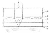
- FIG. 1shows a frontal view of the optical path of an inventive ultrasonic probe.
- FIG. 2shows a side view of the optical path of an inventive ultrasonic probe.
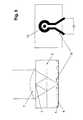
- FIG. 3shows the production of phase-shifted signals on the basis of a schematic diagram.
- FIG. 4shows a second variant for the production of phase-shifted signals on the basis of a schematic diagram.
- FIG. 5shows a method for optimizing the interferometer signal on the basis of a schematic diagram.
- FIGS. 1 and 2show the collimated light coming from the light source strikes a first beam splitter 1 , which it first passes through.
- the lightis focused on the back side by the lenses 2 of the array that are on the front side of a glass panel.
- the membrane 5which is sensitive to ultrasonic waves 7 has a mirrorization 6 on the outside thereof.
- Some of the lightis deflected on a partially reflecting layer 4 and focused on the reference surface 3 which is in the arrangement shown here between the lens and the glass panel.
- the reference surface 3is reflective and can be structured laterally to implement different phase shifts in the reference beam.
- the light reflected on the mirrorization 6 and the reference surface 3is superimposed again on the beam splitter layer 4 and passes through the lenses 2 of the array in the opposite direction for illumination, by which it is collimated again. This light then enters the beam splitter 1 , is separated by it from the illumination beam and focused by the lens 8 on the detector 9 .
- the lens 8 and the detector 9are also arranged in an array where a lens 8 and a detector 9 are assigned to each detection channel (each lens 2 ).
- the lens 2 , partially reflected layer 4 , membrane 5 , mirrorization 6 and reference surface 3are preferably combined with the glass panel as a compact component which functions as a carrier at the same time. This eliminates complex adjustment, and getting out of adjustment due to environmental influences can be minimized.
- the lens 2 , the membrane 5 with mirrorization 6 and the reference surface 3may also be applied to the side faces of the beam splitter 1 . The beam splitting on layer 4 may therefore be omitted, thereby increasing the light efficiency.
- FIG. 3shows a first inventive variant for generating signals with a phase shift of 90°.
- the interferometeris illuminated in a slightly divergent manner, e.g., by not using a laser as the light source but instead using a planar source, the result is an extensive image of this light source on the membrane mirror as well as on the reference surface.
- the membraneSince the membrane is planar and does not have any corresponding height step, with coherent superpositioning of the light reflected there with the light reflected on the stepped reference surface, interference signals with a 90° phase shift are generated. These may be measured by imaging the height step on a two-part detector. The right and left parts of the height step are thus analyzed on separate detector surfaces (detector 9 and 9 ′).
- FIG. 4shows a second inventive variant for generating signals with a 90° phase shift.
- FIG. 2shows a second inventive variant for generating signals with a 90° phase shift.
- the interferometeris illuminated with polarized light, e.g., with linear polarization at a 45° orientation to the x axis of the beam coordinate system.
- polarized lighte.g., with linear polarization at a 45° orientation to the x axis of the beam coordinate system.
- a polarizing beam splitter cubecannot be used for separating the illumination beam and the reflected beam, so asymmetrical illumination can be used as illustrated in FIG. 4 . Otherwise, losses of efficiency must be expected.
- the reference beampasses only through the upper glass panel 10 of the interferometer and thus does not change its linear polarization direction from 45° orientation.
- the measurement beampasses through the lower panel which is designed as a birefringent ⁇ /8 panel 11 .
- the two detectorscan be positioned more independently of one another and need not be arranged closely side by side.
- FIG. 5shows another inventive variant for optimization of the interferometer signal in the side view ( FIG. 5 a ) and in the view from above ( FIG. 5 b ).
- FIG. 5 ashows another inventive variant for optimization of the interferometer signal in the side view ( FIG. 5 a ) and in the view from above ( FIG. 5 b ).
- FIG. 5 bshows another inventive variant for optimization of the interferometer signal in the side view ( FIG. 5 a ) and in the view from above ( FIG. 5 b ).
- FIG. 5shows another inventive variant for optimization of the interferometer signal in the side view ( FIG. 5 a ) and in the view from above ( FIG. 5 b ).
- the deflection of the membrane 6is only in the range of a few nanometers due to the ultrasonic influence, it may happen that with an unfavorable coordination of the lengths of the reference beam path and the measurement beam path, the modulation is only at a maximum or a minimum of the sinusoidal interferometer curve. In this case the resulting electric detector signal is not measurable.
- the monolithic design of the interferometerleads to the stability which is an absolute requirement for the measurement, but it also prevents mechanical tuning of the reference and measurement beam paths with regard to the maximum detector signal at low membrane deflections. This is achieved only when the two beam paths have an average path difference of ⁇ /4 because in this case the average intensity of the interference signal on the detector is on the flank of the sinusoidal signal characteristic of the two-beam interference.
- FIG. 5diagrams one option for implementing the optical paths despite the monolithic design of the interferometer.
- a metallic conductor loop 12is structured here between the membrane layer 5 and the glass carrier. This may be accomplished for example with typical microstructuring processes, whereby the glass carrier serves as a substrate on which a metal layer is applied which is then structured in the form of the conductor loop.
- the focus point of the measurement beam 13 on the membraneis positioned so that it is at the center of the conductor loop. If a current flows through the conductor loop during operation of the measurement system, then its temperature and also the temperature of the ambient medium change as a function of the amperage due to ohmic losses. Thermal expansion of the membrane and glass block as well as the temperature-induced change in refractive index lead to a change in the optical path for the measurement beam. In this way the ratio of the path lengths of the measurement beam and the reference beam can be adapted within certain limits via the current flow through the conductor loop and the interferometer can be tuned to an optimal signal level in the ultrasonic detection.
Landscapes
- Physics & Mathematics (AREA)
- Acoustics & Sound (AREA)
- Engineering & Computer Science (AREA)
- Radar, Positioning & Navigation (AREA)
- Remote Sensing (AREA)
- General Physics & Mathematics (AREA)
- Computer Networks & Wireless Communication (AREA)
- Investigating Or Analyzing Materials By The Use Of Ultrasonic Waves (AREA)
Abstract
Description
Claims (37)
Applications Claiming Priority (4)
| Application Number | Priority Date | Filing Date | Title |
|---|---|---|---|
| DE102006033229.6 | 2006-07-18 | ||
| DE102006033229 | 2006-07-18 | ||
| DE102006033229ADE102006033229B4 (en) | 2006-07-18 | 2006-07-18 | Ultrasonic probe and method for the optical detection of ultrasonic waves |
| PCT/EP2007/006396WO2008009442A2 (en) | 2006-07-18 | 2007-07-18 | Ultrasonic probe and method for the optical detection of ultrasonic waves |
Publications (2)
| Publication Number | Publication Date |
|---|---|
| US20100043561A1 US20100043561A1 (en) | 2010-02-25 |
| US8240211B2true US8240211B2 (en) | 2012-08-14 |
Family
ID=38870599
Family Applications (1)
| Application Number | Title | Priority Date | Filing Date |
|---|---|---|---|
| US12/373,374Active2028-11-06US8240211B2 (en) | 2006-07-18 | 2007-07-18 | Ultrasonic probe and method for the optical detection of ultrasonic waves |
Country Status (4)
| Country | Link |
|---|---|
| US (1) | US8240211B2 (en) |
| EP (1) | EP2041534A2 (en) |
| DE (1) | DE102006033229B4 (en) |
| WO (1) | WO2008009442A2 (en) |
Cited By (33)
| Publication number | Priority date | Publication date | Assignee | Title |
|---|---|---|---|---|
| US20100317981A1 (en)* | 2009-06-12 | 2010-12-16 | Romedex International Srl | Catheter Tip Positioning Method |
| US8784336B2 (en) | 2005-08-24 | 2014-07-22 | C. R. Bard, Inc. | Stylet apparatuses and methods of manufacture |
| US8849382B2 (en) | 2007-11-26 | 2014-09-30 | C. R. Bard, Inc. | Apparatus and display methods relating to intravascular placement of a catheter |
| US8858455B2 (en) | 2006-10-23 | 2014-10-14 | Bard Access Systems, Inc. | Method of locating the tip of a central venous catheter |
| US9125578B2 (en) | 2009-06-12 | 2015-09-08 | Bard Access Systems, Inc. | Apparatus and method for catheter navigation and tip location |
| US9265443B2 (en) | 2006-10-23 | 2016-02-23 | Bard Access Systems, Inc. | Method of locating the tip of a central venous catheter |
| US9415188B2 (en) | 2010-10-29 | 2016-08-16 | C. R. Bard, Inc. | Bioimpedance-assisted placement of a medical device |
| US9445734B2 (en) | 2009-06-12 | 2016-09-20 | Bard Access Systems, Inc. | Devices and methods for endovascular electrography |
| US9456766B2 (en) | 2007-11-26 | 2016-10-04 | C. R. Bard, Inc. | Apparatus for use with needle insertion guidance system |
| US9492097B2 (en) | 2007-11-26 | 2016-11-15 | C. R. Bard, Inc. | Needle length determination and calibration for insertion guidance system |
| US9521961B2 (en) | 2007-11-26 | 2016-12-20 | C. R. Bard, Inc. | Systems and methods for guiding a medical instrument |
| US9526440B2 (en) | 2007-11-26 | 2016-12-27 | C.R. Bard, Inc. | System for placement of a catheter including a signal-generating stylet |
| US9532724B2 (en) | 2009-06-12 | 2017-01-03 | Bard Access Systems, Inc. | Apparatus and method for catheter navigation using endovascular energy mapping |
| US9554716B2 (en) | 2007-11-26 | 2017-01-31 | C. R. Bard, Inc. | Insertion guidance system for needles and medical components |
| US9636031B2 (en) | 2007-11-26 | 2017-05-02 | C.R. Bard, Inc. | Stylets for use with apparatus for intravascular placement of a catheter |
| US9649048B2 (en) | 2007-11-26 | 2017-05-16 | C. R. Bard, Inc. | Systems and methods for breaching a sterile field for intravascular placement of a catheter |
| US9681823B2 (en) | 2007-11-26 | 2017-06-20 | C. R. Bard, Inc. | Integrated system for intravascular placement of a catheter |
| US9839372B2 (en) | 2014-02-06 | 2017-12-12 | C. R. Bard, Inc. | Systems and methods for guidance and placement of an intravascular device |
| US9901714B2 (en) | 2008-08-22 | 2018-02-27 | C. R. Bard, Inc. | Catheter assembly including ECG sensor and magnetic assemblies |
| US9907513B2 (en) | 2008-10-07 | 2018-03-06 | Bard Access Systems, Inc. | Percutaneous magnetic gastrostomy |
| US10046139B2 (en) | 2010-08-20 | 2018-08-14 | C. R. Bard, Inc. | Reconfirmation of ECG-assisted catheter tip placement |
| US10349890B2 (en) | 2015-06-26 | 2019-07-16 | C. R. Bard, Inc. | Connector interface for ECG-based catheter positioning system |
| US10449330B2 (en) | 2007-11-26 | 2019-10-22 | C. R. Bard, Inc. | Magnetic element-equipped needle assemblies |
| US10524691B2 (en) | 2007-11-26 | 2020-01-07 | C. R. Bard, Inc. | Needle assembly including an aligned magnetic element |
| US10751509B2 (en) | 2007-11-26 | 2020-08-25 | C. R. Bard, Inc. | Iconic representations for guidance of an indwelling medical device |
| US10973584B2 (en) | 2015-01-19 | 2021-04-13 | Bard Access Systems, Inc. | Device and method for vascular access |
| US10992079B2 (en) | 2018-10-16 | 2021-04-27 | Bard Access Systems, Inc. | Safety-equipped connection systems and methods thereof for establishing electrical connections |
| US11000207B2 (en) | 2016-01-29 | 2021-05-11 | C. R. Bard, Inc. | Multiple coil system for tracking a medical device |
| US11369410B2 (en) | 2017-04-27 | 2022-06-28 | Bard Access Systems, Inc. | Magnetizing system for needle assemblies including orientation key system for positioning needle tray in magnetizer |
| US11911140B2 (en) | 2020-11-09 | 2024-02-27 | Bard Access Systems, Inc. | Medical device magnetizer |
| US12059243B2 (en) | 2020-11-10 | 2024-08-13 | Bard Access Systems, Inc. | Sterile cover for medical devices and methods thereof |
| US12230427B2 (en) | 2021-07-26 | 2025-02-18 | Bard Access Systems, Inc. | Medical-device magnetizer systems and methods |
| US12232826B2 (en) | 2021-06-22 | 2025-02-25 | Bard Access Systems, Inc. | Medical device magnetizer system with indicators |
Families Citing this family (2)
| Publication number | Priority date | Publication date | Assignee | Title |
|---|---|---|---|---|
| EP2015105B1 (en) | 2007-07-13 | 2011-06-08 | eZono AG | Opto-electrical ultrasound sensor and system |
| US20150230450A1 (en)* | 2014-02-20 | 2015-08-20 | Turtle Beach Corporation | Ultrasonic intrusion deterrence apparatus and methods |
Citations (21)
| Publication number | Priority date | Publication date | Assignee | Title |
|---|---|---|---|---|
| US3882718A (en) | 1971-05-05 | 1975-05-13 | American Optical Corp | Noncontacting pressure measuring apparatus |
| DE3334112A1 (en) | 1982-09-22 | 1984-03-22 | Rhône-Poulenc Fibres, 69003 Lyon | METHOD AND DEVICE FOR THE CONTACT-FREE MEASUREMENT OF THE TENSION OF THREAD-SHAPED PRODUCTS AND SURFACES IN MOTION |
| US4833928A (en) | 1986-06-09 | 1989-05-30 | Stromberg Oy | Method and apparatus for noncontacting tension measurement in a flat foil and especially in a paper web |
| DE3932711A1 (en) | 1989-09-29 | 1991-04-11 | Siemens Ag | OPTICAL SHOCK WAVE SENSOR |
| US5894531A (en)* | 1997-03-11 | 1999-04-13 | Karta Technology, Inc. | Method and apparatus for detection of ultrasound using a fiber-optic interferometer |
| US6134006A (en)* | 1998-02-25 | 2000-10-17 | Becthel Bwxt Idaho, Llc | Imaging photorefractive optical vibration measurement method and device |
| EP1152240A2 (en) | 2000-05-02 | 2001-11-07 | Fuji Photo Film Co., Ltd. | Ultrasonic probe and ultrasonic diagnosis apparatus using the same |
| EP1158283A1 (en) | 2000-05-23 | 2001-11-28 | Fuji Photo Film Co., Ltd. | Dynamic change detecting method, dynamic change detecting apparatus and ultrasonic diagnostic apparatus |
| EP1348980A2 (en) | 2002-03-26 | 2003-10-01 | Fuji Photo Film Co. Ltd. | Ultrasonic receiving apparatus and ultrasonic receiving method |
| US20040071383A1 (en) | 2002-10-15 | 2004-04-15 | Balakumar Balachandran | Fiber tip based sensor system for acoustic measurements |
| DE10335988A1 (en) | 2002-11-29 | 2004-06-17 | Siemens Ag | Optical hydrophone for measuring the sound pressure distribution in a fluid medium |
| DE10359663A1 (en) | 2003-12-18 | 2005-07-28 | Siemens Ag | Optical hydrophone for measuring the sound pressure distribution in a fluid medium |
| US6958817B1 (en)* | 2004-08-13 | 2005-10-25 | Nanyang Technological University | Method of interferometry with modulated optical path-length difference and interferometer |
| DE102004052205A1 (en) | 2004-10-20 | 2006-05-04 | Universität Stuttgart | Interferometric method e.g. for recording of separation and form and optical coherence tomography (OCT), involves having multi-wavelength source or tunable source and imaging on receiver by focusing systems |
| US7116426B2 (en)* | 2003-03-31 | 2006-10-03 | Metrolaser | Multi-beam heterodyne laser Doppler vibrometer |
| US7590312B2 (en)* | 2003-07-04 | 2009-09-15 | Nippon Telegraph And Telephone Corporation | Interferometer optical switch and variable optical attenuator |
| US7667851B2 (en)* | 2001-07-24 | 2010-02-23 | Lockheed Martin Corporation | Method and apparatus for using a two-wave mixing ultrasonic detection in rapid scanning applications |
| US20100128278A1 (en)* | 2008-11-26 | 2010-05-27 | Zygo Corporation | Fiber-based interferometer system for monitoring an imaging interferometer |
| US20100210950A1 (en)* | 2007-07-13 | 2010-08-19 | Ezono Ag | Opto-electrical ultrasound sensor and system |
| US7782467B2 (en)* | 2005-01-25 | 2010-08-24 | Debiotech S.A. | Method for measuring volume by an optical surface profilometer in a micromechanical device and a system for carrying out said measurement |
| US8004689B2 (en)* | 2006-05-10 | 2011-08-23 | National Research Council Of Canada | Method of assessing bond integrity in bonded structures |
Family Cites Families (3)
| Publication number | Priority date | Publication date | Assignee | Title |
|---|---|---|---|---|
| US4639139A (en)* | 1985-09-27 | 1987-01-27 | Wyko Corporation | Optical profiler using improved phase shifting interferometry |
| US6392752B1 (en)* | 1999-06-14 | 2002-05-21 | Kenneth Carlisle Johnson | Phase-measuring microlens microscopy |
| US7283250B2 (en)* | 2004-01-16 | 2007-10-16 | Veeco Instruments, Inc. | Measurement of object deformation with optical profiler |
- 2006
- 2006-07-18DEDE102006033229Apatent/DE102006033229B4/ennot_activeExpired - Fee Related
- 2007
- 2007-07-18EPEP07786169Apatent/EP2041534A2/ennot_activeWithdrawn
- 2007-07-18WOPCT/EP2007/006396patent/WO2008009442A2/enactiveApplication Filing
- 2007-07-18USUS12/373,374patent/US8240211B2/enactiveActive
Patent Citations (27)
| Publication number | Priority date | Publication date | Assignee | Title |
|---|---|---|---|---|
| US3882718A (en) | 1971-05-05 | 1975-05-13 | American Optical Corp | Noncontacting pressure measuring apparatus |
| DE3334112A1 (en) | 1982-09-22 | 1984-03-22 | Rhône-Poulenc Fibres, 69003 Lyon | METHOD AND DEVICE FOR THE CONTACT-FREE MEASUREMENT OF THE TENSION OF THREAD-SHAPED PRODUCTS AND SURFACES IN MOTION |
| GB2127544A (en) | 1982-09-22 | 1984-04-11 | Rhone Poulenc Fibres | Measuring tension |
| US4833928A (en) | 1986-06-09 | 1989-05-30 | Stromberg Oy | Method and apparatus for noncontacting tension measurement in a flat foil and especially in a paper web |
| CH674262A5 (en) | 1986-06-09 | 1990-05-15 | Stroemberg Oy Ab | |
| DE3932711A1 (en) | 1989-09-29 | 1991-04-11 | Siemens Ag | OPTICAL SHOCK WAVE SENSOR |
| US5894531A (en)* | 1997-03-11 | 1999-04-13 | Karta Technology, Inc. | Method and apparatus for detection of ultrasound using a fiber-optic interferometer |
| US6134006A (en)* | 1998-02-25 | 2000-10-17 | Becthel Bwxt Idaho, Llc | Imaging photorefractive optical vibration measurement method and device |
| EP1152240A2 (en) | 2000-05-02 | 2001-11-07 | Fuji Photo Film Co., Ltd. | Ultrasonic probe and ultrasonic diagnosis apparatus using the same |
| US6609425B2 (en) | 2000-05-02 | 2003-08-26 | Fuji Photo Film Co., Ltd. | Ultrasonic probe and ultrasonic diagnosis apparatus using the same |
| EP1158283A1 (en) | 2000-05-23 | 2001-11-28 | Fuji Photo Film Co., Ltd. | Dynamic change detecting method, dynamic change detecting apparatus and ultrasonic diagnostic apparatus |
| US6594290B2 (en) | 2000-05-23 | 2003-07-15 | Fuji Photo Film Co., Ltd. | Dynamic change detecting method, dynamic change detecting apparatus and ultrasonic diagnostic apparatus |
| US7667851B2 (en)* | 2001-07-24 | 2010-02-23 | Lockheed Martin Corporation | Method and apparatus for using a two-wave mixing ultrasonic detection in rapid scanning applications |
| EP1348980A2 (en) | 2002-03-26 | 2003-10-01 | Fuji Photo Film Co. Ltd. | Ultrasonic receiving apparatus and ultrasonic receiving method |
| US6881189B2 (en) | 2002-03-26 | 2005-04-19 | Fuji Photo Film Co., Ltd. | Ultrasonic receiving apparatus and ultrasonic receiving method |
| US6901176B2 (en) | 2002-10-15 | 2005-05-31 | University Of Maryland | Fiber tip based sensor system for acoustic measurements |
| US20040071383A1 (en) | 2002-10-15 | 2004-04-15 | Balakumar Balachandran | Fiber tip based sensor system for acoustic measurements |
| DE10335988A1 (en) | 2002-11-29 | 2004-06-17 | Siemens Ag | Optical hydrophone for measuring the sound pressure distribution in a fluid medium |
| US7116426B2 (en)* | 2003-03-31 | 2006-10-03 | Metrolaser | Multi-beam heterodyne laser Doppler vibrometer |
| US7590312B2 (en)* | 2003-07-04 | 2009-09-15 | Nippon Telegraph And Telephone Corporation | Interferometer optical switch and variable optical attenuator |
| DE10359663A1 (en) | 2003-12-18 | 2005-07-28 | Siemens Ag | Optical hydrophone for measuring the sound pressure distribution in a fluid medium |
| US6958817B1 (en)* | 2004-08-13 | 2005-10-25 | Nanyang Technological University | Method of interferometry with modulated optical path-length difference and interferometer |
| DE102004052205A1 (en) | 2004-10-20 | 2006-05-04 | Universität Stuttgart | Interferometric method e.g. for recording of separation and form and optical coherence tomography (OCT), involves having multi-wavelength source or tunable source and imaging on receiver by focusing systems |
| US7782467B2 (en)* | 2005-01-25 | 2010-08-24 | Debiotech S.A. | Method for measuring volume by an optical surface profilometer in a micromechanical device and a system for carrying out said measurement |
| US8004689B2 (en)* | 2006-05-10 | 2011-08-23 | National Research Council Of Canada | Method of assessing bond integrity in bonded structures |
| US20100210950A1 (en)* | 2007-07-13 | 2010-08-19 | Ezono Ag | Opto-electrical ultrasound sensor and system |
| US20100128278A1 (en)* | 2008-11-26 | 2010-05-27 | Zygo Corporation | Fiber-based interferometer system for monitoring an imaging interferometer |
Non-Patent Citations (2)
| Title |
|---|
| Hlubina, Peter, Measuring Distances and Displacements Using Dispersive White-Light Spectral Interferometry, Proceedings of SPIE, 2003, pp. 628-636, vol. 5144. |
| Mehta, Dalip Singh, Saito, Shohei, Hinosugi, Hideki, Takeda, Mitsuo, Kurokawa, Takashi, Spectral Interference Mirau Microscope With an Acousto-Optic Tunable Filter for Three-Dimensional Surface Profilometry, Applied Optics, Mar. 2003, pp. 1296-1305, vol. 42, No. 7. |
Cited By (63)
| Publication number | Priority date | Publication date | Assignee | Title |
|---|---|---|---|---|
| US8784336B2 (en) | 2005-08-24 | 2014-07-22 | C. R. Bard, Inc. | Stylet apparatuses and methods of manufacture |
| US11207496B2 (en) | 2005-08-24 | 2021-12-28 | C. R. Bard, Inc. | Stylet apparatuses and methods of manufacture |
| US10004875B2 (en) | 2005-08-24 | 2018-06-26 | C. R. Bard, Inc. | Stylet apparatuses and methods of manufacture |
| US9345422B2 (en) | 2006-10-23 | 2016-05-24 | Bard Acess Systems, Inc. | Method of locating the tip of a central venous catheter |
| US8858455B2 (en) | 2006-10-23 | 2014-10-14 | Bard Access Systems, Inc. | Method of locating the tip of a central venous catheter |
| US9265443B2 (en) | 2006-10-23 | 2016-02-23 | Bard Access Systems, Inc. | Method of locating the tip of a central venous catheter |
| US9833169B2 (en) | 2006-10-23 | 2017-12-05 | Bard Access Systems, Inc. | Method of locating the tip of a central venous catheter |
| US10238418B2 (en) | 2007-11-26 | 2019-03-26 | C. R. Bard, Inc. | Apparatus for use with needle insertion guidance system |
| US10449330B2 (en) | 2007-11-26 | 2019-10-22 | C. R. Bard, Inc. | Magnetic element-equipped needle assemblies |
| US11779240B2 (en) | 2007-11-26 | 2023-10-10 | C. R. Bard, Inc. | Systems and methods for breaching a sterile field for intravascular placement of a catheter |
| US9456766B2 (en) | 2007-11-26 | 2016-10-04 | C. R. Bard, Inc. | Apparatus for use with needle insertion guidance system |
| US9492097B2 (en) | 2007-11-26 | 2016-11-15 | C. R. Bard, Inc. | Needle length determination and calibration for insertion guidance system |
| US9521961B2 (en) | 2007-11-26 | 2016-12-20 | C. R. Bard, Inc. | Systems and methods for guiding a medical instrument |
| US9526440B2 (en) | 2007-11-26 | 2016-12-27 | C.R. Bard, Inc. | System for placement of a catheter including a signal-generating stylet |
| US11707205B2 (en) | 2007-11-26 | 2023-07-25 | C. R. Bard, Inc. | Integrated system for intravascular placement of a catheter |
| US9549685B2 (en) | 2007-11-26 | 2017-01-24 | C. R. Bard, Inc. | Apparatus and display methods relating to intravascular placement of a catheter |
| US9554716B2 (en) | 2007-11-26 | 2017-01-31 | C. R. Bard, Inc. | Insertion guidance system for needles and medical components |
| US9636031B2 (en) | 2007-11-26 | 2017-05-02 | C.R. Bard, Inc. | Stylets for use with apparatus for intravascular placement of a catheter |
| US9649048B2 (en) | 2007-11-26 | 2017-05-16 | C. R. Bard, Inc. | Systems and methods for breaching a sterile field for intravascular placement of a catheter |
| US9681823B2 (en) | 2007-11-26 | 2017-06-20 | C. R. Bard, Inc. | Integrated system for intravascular placement of a catheter |
| US11529070B2 (en) | 2007-11-26 | 2022-12-20 | C. R. Bard, Inc. | System and methods for guiding a medical instrument |
| US8849382B2 (en) | 2007-11-26 | 2014-09-30 | C. R. Bard, Inc. | Apparatus and display methods relating to intravascular placement of a catheter |
| US11134915B2 (en) | 2007-11-26 | 2021-10-05 | C. R. Bard, Inc. | System for placement of a catheter including a signal-generating stylet |
| US11123099B2 (en) | 2007-11-26 | 2021-09-21 | C. R. Bard, Inc. | Apparatus for use with needle insertion guidance system |
| US9999371B2 (en) | 2007-11-26 | 2018-06-19 | C. R. Bard, Inc. | Integrated system for intravascular placement of a catheter |
| US10966630B2 (en) | 2007-11-26 | 2021-04-06 | C. R. Bard, Inc. | Integrated system for intravascular placement of a catheter |
| US10849695B2 (en) | 2007-11-26 | 2020-12-01 | C. R. Bard, Inc. | Systems and methods for breaching a sterile field for intravascular placement of a catheter |
| US10105121B2 (en) | 2007-11-26 | 2018-10-23 | C. R. Bard, Inc. | System for placement of a catheter including a signal-generating stylet |
| US10165962B2 (en) | 2007-11-26 | 2019-01-01 | C. R. Bard, Inc. | Integrated systems for intravascular placement of a catheter |
| US10231753B2 (en) | 2007-11-26 | 2019-03-19 | C. R. Bard, Inc. | Insertion guidance system for needles and medical components |
| US10751509B2 (en) | 2007-11-26 | 2020-08-25 | C. R. Bard, Inc. | Iconic representations for guidance of an indwelling medical device |
| US10602958B2 (en) | 2007-11-26 | 2020-03-31 | C. R. Bard, Inc. | Systems and methods for guiding a medical instrument |
| US10524691B2 (en) | 2007-11-26 | 2020-01-07 | C. R. Bard, Inc. | Needle assembly including an aligned magnetic element |
| US10342575B2 (en) | 2007-11-26 | 2019-07-09 | C. R. Bard, Inc. | Apparatus for use with needle insertion guidance system |
| US11027101B2 (en) | 2008-08-22 | 2021-06-08 | C. R. Bard, Inc. | Catheter assembly including ECG sensor and magnetic assemblies |
| US9901714B2 (en) | 2008-08-22 | 2018-02-27 | C. R. Bard, Inc. | Catheter assembly including ECG sensor and magnetic assemblies |
| US9907513B2 (en) | 2008-10-07 | 2018-03-06 | Bard Access Systems, Inc. | Percutaneous magnetic gastrostomy |
| US9125578B2 (en) | 2009-06-12 | 2015-09-08 | Bard Access Systems, Inc. | Apparatus and method for catheter navigation and tip location |
| US9532724B2 (en) | 2009-06-12 | 2017-01-03 | Bard Access Systems, Inc. | Apparatus and method for catheter navigation using endovascular energy mapping |
| US10271762B2 (en) | 2009-06-12 | 2019-04-30 | Bard Access Systems, Inc. | Apparatus and method for catheter navigation using endovascular energy mapping |
| US10912488B2 (en) | 2009-06-12 | 2021-02-09 | Bard Access Systems, Inc. | Apparatus and method for catheter navigation and tip location |
| US9445734B2 (en) | 2009-06-12 | 2016-09-20 | Bard Access Systems, Inc. | Devices and methods for endovascular electrography |
| US10231643B2 (en) | 2009-06-12 | 2019-03-19 | Bard Access Systems, Inc. | Apparatus and method for catheter navigation and tip location |
| US20100317981A1 (en)* | 2009-06-12 | 2010-12-16 | Romedex International Srl | Catheter Tip Positioning Method |
| US9339206B2 (en) | 2009-06-12 | 2016-05-17 | Bard Access Systems, Inc. | Adaptor for endovascular electrocardiography |
| US11419517B2 (en) | 2009-06-12 | 2022-08-23 | Bard Access Systems, Inc. | Apparatus and method for catheter navigation using endovascular energy mapping |
| US10046139B2 (en) | 2010-08-20 | 2018-08-14 | C. R. Bard, Inc. | Reconfirmation of ECG-assisted catheter tip placement |
| US9415188B2 (en) | 2010-10-29 | 2016-08-16 | C. R. Bard, Inc. | Bioimpedance-assisted placement of a medical device |
| US9839372B2 (en) | 2014-02-06 | 2017-12-12 | C. R. Bard, Inc. | Systems and methods for guidance and placement of an intravascular device |
| US10863920B2 (en) | 2014-02-06 | 2020-12-15 | C. R. Bard, Inc. | Systems and methods for guidance and placement of an intravascular device |
| US10973584B2 (en) | 2015-01-19 | 2021-04-13 | Bard Access Systems, Inc. | Device and method for vascular access |
| US10349890B2 (en) | 2015-06-26 | 2019-07-16 | C. R. Bard, Inc. | Connector interface for ECG-based catheter positioning system |
| US11026630B2 (en) | 2015-06-26 | 2021-06-08 | C. R. Bard, Inc. | Connector interface for ECG-based catheter positioning system |
| US11000207B2 (en) | 2016-01-29 | 2021-05-11 | C. R. Bard, Inc. | Multiple coil system for tracking a medical device |
| US12207840B2 (en) | 2017-04-27 | 2025-01-28 | Bard Access Systems, Inc. | Magnetizing system for needle assemblies |
| US11369410B2 (en) | 2017-04-27 | 2022-06-28 | Bard Access Systems, Inc. | Magnetizing system for needle assemblies including orientation key system for positioning needle tray in magnetizer |
| US11621518B2 (en) | 2018-10-16 | 2023-04-04 | Bard Access Systems, Inc. | Safety-equipped connection systems and methods thereof for establishing electrical connections |
| US10992079B2 (en) | 2018-10-16 | 2021-04-27 | Bard Access Systems, Inc. | Safety-equipped connection systems and methods thereof for establishing electrical connections |
| US11911140B2 (en) | 2020-11-09 | 2024-02-27 | Bard Access Systems, Inc. | Medical device magnetizer |
| US12239428B2 (en) | 2020-11-09 | 2025-03-04 | Bard Access Systems, Inc. | Medical device magnetizer |
| US12059243B2 (en) | 2020-11-10 | 2024-08-13 | Bard Access Systems, Inc. | Sterile cover for medical devices and methods thereof |
| US12232826B2 (en) | 2021-06-22 | 2025-02-25 | Bard Access Systems, Inc. | Medical device magnetizer system with indicators |
| US12230427B2 (en) | 2021-07-26 | 2025-02-18 | Bard Access Systems, Inc. | Medical-device magnetizer systems and methods |
Also Published As
| Publication number | Publication date |
|---|---|
| EP2041534A2 (en) | 2009-04-01 |
| DE102006033229A1 (en) | 2008-02-07 |
| WO2008009442A8 (en) | 2008-04-17 |
| WO2008009442A2 (en) | 2008-01-24 |
| DE102006033229B4 (en) | 2013-05-08 |
| WO2008009442A3 (en) | 2008-03-13 |
| US20100043561A1 (en) | 2010-02-25 |
Similar Documents
| Publication | Publication Date | Title |
|---|---|---|
| US8240211B2 (en) | Ultrasonic probe and method for the optical detection of ultrasonic waves | |
| JP7402868B2 (en) | Descan correction in scanning LIDAR | |
| US7139446B2 (en) | Compact fiber optic geometry for a counter-chirp FMCW coherent laser radar | |
| US9155517B2 (en) | Opto-electrical ultrasound sensor and system | |
| JP5752040B2 (en) | Compact optical fiber arrangement for anti-chirp FMCW coherent laser radar | |
| JPWO2011093108A1 (en) | Ultrasonic probe and ultrasonic inspection apparatus using the same | |
| CN113167865A (en) | Polarization-Encoded Beam Transmission and Collection | |
| KR101544962B1 (en) | Transmission-type Interference Apparatus using Optical Fibers for Measuring Geometrical Thickness and Refractive index | |
| US6709393B2 (en) | Ultrasonic receiving apparatus and ultrasonic receiving method | |
| KR20010102913A (en) | Dynamic change detecting method, dynamic change detecting apparatus and ultrasonic diagnostic apparatus | |
| US6984819B2 (en) | Optical converting type ultrasonic receiving apparatus | |
| EP1158283B1 (en) | Dynamic change detecting method, dynamic change detecting apparatus and ultrasonic diagnostic apparatus | |
| US6783494B2 (en) | Ultrasonic probe and ultrasonic diagnosing apparatus using the same | |
| US6470752B2 (en) | Ultrasonic detection method and apparatus and ultrasonic diagnostic apparatus | |
| KR20030027833A (en) | Ultrasonic receiving apparatus and ultrasonic diagnosing apparatus using the same | |
| US7048689B2 (en) | Ultrasonic receiving apparatus and ultrasonic receiving method | |
| US7359063B2 (en) | Heterodyne array detector | |
| JP3995612B2 (en) | Ultrasonic receiving apparatus and ultrasonic receiving method | |
| JP4076873B2 (en) | Ultrasonic receiving apparatus and ultrasonic receiving method | |
| Sheaff et al. | High resolution imaging with a polyimide-etalon all-optical ultrasound transducer |
Legal Events
| Date | Code | Title | Description |
|---|---|---|---|
| AS | Assignment | Owner name:FRAUNHOFER-GESELLSCHAFT ZUR FORDERUNG DER ANGEWAND Free format text:ASSIGNMENT OF ASSIGNORS INTEREST;ASSIGNORS:ZEITNER, UWE DETLEF;SCHETS, SICCO IAN;SOBRINO, ELISEO VENTURA;SIGNING DATES FROM 20090109 TO 20090114;REEL/FRAME:022340/0062 Owner name:EZONO AG,GERMANY Free format text:ASSIGNMENT OF ASSIGNORS INTEREST;ASSIGNORS:ZEITNER, UWE DETLEF;SCHETS, SICCO IAN;SOBRINO, ELISEO VENTURA;SIGNING DATES FROM 20090109 TO 20090114;REEL/FRAME:022340/0062 Owner name:EZONO AG, GERMANY Free format text:ASSIGNMENT OF ASSIGNORS INTEREST;ASSIGNORS:ZEITNER, UWE DETLEF;SCHETS, SICCO IAN;SOBRINO, ELISEO VENTURA;SIGNING DATES FROM 20090109 TO 20090114;REEL/FRAME:022340/0062 | |
| STCF | Information on status: patent grant | Free format text:PATENTED CASE | |
| FPAY | Fee payment | Year of fee payment:4 | |
| AS | Assignment | Owner name:EZONO AG, GERMANY Free format text:ASSIGNMENT OF ASSIGNORS INTEREST;ASSIGNOR:FRAUNHOFER-GESELLSCHAFT ZUR FOERDERUNG DER ANGEWANDTEN FORSCHUNG E.V.;REEL/FRAME:041160/0123 Effective date:20170126 | |
| MAFP | Maintenance fee payment | Free format text:PAYMENT OF MAINTENANCE FEE, 8TH YEAR, LARGE ENTITY (ORIGINAL EVENT CODE: M1552); ENTITY STATUS OF PATENT OWNER: LARGE ENTITY Year of fee payment:8 | |
| MAFP | Maintenance fee payment | Free format text:PAYMENT OF MAINTENANCE FEE, 12TH YEAR, LARGE ENTITY (ORIGINAL EVENT CODE: M1553); ENTITY STATUS OF PATENT OWNER: LARGE ENTITY Year of fee payment:12 |