US8240150B2 - Lean direct injection diffusion tip and related method - Google Patents
Lean direct injection diffusion tip and related methodDownload PDFInfo
- Publication number
- US8240150B2 US8240150B2US12/222,423US22242308AUS8240150B2US 8240150 B2US8240150 B2US 8240150B2US 22242308 AUS22242308 AUS 22242308AUS 8240150 B2US8240150 B2US 8240150B2
- Authority
- US
- United States
- Prior art keywords
- fuel
- air
- passages
- radially
- center body
- Prior art date
- Legal status (The legal status is an assumption and is not a legal conclusion. Google has not performed a legal analysis and makes no representation as to the accuracy of the status listed.)
- Expired - Fee Related, expires
Links
- 238000000034methodMethods0.000titleclaimsdescription9
- 238000009792diffusion processMethods0.000titledescription9
- 238000002347injectionMethods0.000titledescription9
- 239000007924injectionSubstances0.000titledescription9
- 239000000446fuelSubstances0.000claimsabstractdescription97
- 238000006243chemical reactionMethods0.000claimsabstractdescription29
- 238000011144upstream manufacturingMethods0.000claimsdescription7
- 238000004891communicationMethods0.000claimsdescription3
- MWUXSHHQAYIFBG-UHFFFAOYSA-NNitric oxideChemical compoundO=[N]MWUXSHHQAYIFBG-UHFFFAOYSA-N0.000description36
- 239000007789gasSubstances0.000description10
- 238000002485combustion reactionMethods0.000description9
- 239000000203mixtureSubstances0.000description5
- 239000000567combustion gasSubstances0.000description4
- 239000003085diluting agentSubstances0.000description3
- 230000001965increasing effectEffects0.000description3
- IJGRMHOSHXDMSA-UHFFFAOYSA-NAtomic nitrogenChemical compoundN#NIJGRMHOSHXDMSA-UHFFFAOYSA-N0.000description2
- UFHFLCQGNIYNRP-UHFFFAOYSA-NHydrogenChemical compound[H][H]UFHFLCQGNIYNRP-UHFFFAOYSA-N0.000description2
- 230000015572biosynthetic processEffects0.000description2
- 239000001257hydrogenSubstances0.000description2
- 229910052739hydrogenInorganic materials0.000description2
- 239000003701inert diluentSubstances0.000description2
- 230000002411adverseEffects0.000description1
- 239000003570airSubstances0.000description1
- 238000003491arrayMethods0.000description1
- QVGXLLKOCUKJST-UHFFFAOYSA-Natomic oxygenChemical compound[O]QVGXLLKOCUKJST-UHFFFAOYSA-N0.000description1
- 230000009286beneficial effectEffects0.000description1
- 239000006227byproductSubstances0.000description1
- 238000010276constructionMethods0.000description1
- 230000002708enhancing effectEffects0.000description1
- 238000012986modificationMethods0.000description1
- 230000004048modificationEffects0.000description1
- 229910052757nitrogenInorganic materials0.000description1
- 239000001301oxygenSubstances0.000description1
- 229910052760oxygenInorganic materials0.000description1
- 230000001105regulatory effectEffects0.000description1
Images


Classifications
- F—MECHANICAL ENGINEERING; LIGHTING; HEATING; WEAPONS; BLASTING
- F23—COMBUSTION APPARATUS; COMBUSTION PROCESSES
- F23R—GENERATING COMBUSTION PRODUCTS OF HIGH PRESSURE OR HIGH VELOCITY, e.g. GAS-TURBINE COMBUSTION CHAMBERS
- F23R3/00—Continuous combustion chambers using liquid or gaseous fuel
- F23R3/02—Continuous combustion chambers using liquid or gaseous fuel characterised by the air-flow or gas-flow configuration
- F23R3/04—Air inlet arrangements
- F23R3/10—Air inlet arrangements for primary air
- F23R3/12—Air inlet arrangements for primary air inducing a vortex
- F23R3/14—Air inlet arrangements for primary air inducing a vortex by using swirl vanes
- F—MECHANICAL ENGINEERING; LIGHTING; HEATING; WEAPONS; BLASTING
- F23—COMBUSTION APPARATUS; COMBUSTION PROCESSES
- F23R—GENERATING COMBUSTION PRODUCTS OF HIGH PRESSURE OR HIGH VELOCITY, e.g. GAS-TURBINE COMBUSTION CHAMBERS
- F23R3/00—Continuous combustion chambers using liquid or gaseous fuel
- F23R3/28—Continuous combustion chambers using liquid or gaseous fuel characterised by the fuel supply
- F23R3/286—Continuous combustion chambers using liquid or gaseous fuel characterised by the fuel supply having fuel-air premixing devices
- F—MECHANICAL ENGINEERING; LIGHTING; HEATING; WEAPONS; BLASTING
- F23—COMBUSTION APPARATUS; COMBUSTION PROCESSES
- F23R—GENERATING COMBUSTION PRODUCTS OF HIGH PRESSURE OR HIGH VELOCITY, e.g. GAS-TURBINE COMBUSTION CHAMBERS
- F23R3/00—Continuous combustion chambers using liquid or gaseous fuel
- F23R3/28—Continuous combustion chambers using liquid or gaseous fuel characterised by the fuel supply
- F23R3/34—Feeding into different combustion zones
- F23R3/343—Pilot flames, i.e. fuel nozzles or injectors using only a very small proportion of the total fuel to insure continuous combustion
- F—MECHANICAL ENGINEERING; LIGHTING; HEATING; WEAPONS; BLASTING
- F23—COMBUSTION APPARATUS; COMBUSTION PROCESSES
- F23D—BURNERS
- F23D2900/00—Special features of, or arrangements for burners using fluid fuels or solid fuels suspended in a carrier gas
- F23D2900/00008—Burner assemblies with diffusion and premix modes, i.e. dual mode burners
- F—MECHANICAL ENGINEERING; LIGHTING; HEATING; WEAPONS; BLASTING
- F23—COMBUSTION APPARATUS; COMBUSTION PROCESSES
- F23D—BURNERS
- F23D2900/00—Special features of, or arrangements for burners using fluid fuels or solid fuels suspended in a carrier gas
- F23D2900/14—Special features of gas burners
- F23D2900/14004—Special features of gas burners with radially extending gas distribution spokes
Definitions
- This inventionrelates generally to turbine combustion and more particularly, to a lean direct injection nozzle for achieving lower NO x emissions.
- At least some known gas turbine enginescombust a fuel air mixture to release heat energy from the mixture to form a high temperature combustion gas stream that is channeled to a turbine via a hot gas path.
- the turbineconverts thermal energy from the combustion gas stream to mechanical energy that rotates a turbine shaft.
- the output of the turbinemay be used to power a machine, for example, an electric generator, pump, or the like.
- At least one by-product of the combustion reactionmay be subject to regulatory limitations.
- nitrogen oxide (NO x )may be formed by a reaction between nitrogen and oxygen in the air initiated by the high temperatures within the gas turbine engine.
- engine efficiencyincreases as the combustion gas stream temperature entering a turbine section of the gas engine increases; however, increasing the combustion gas temperature may facilitate an increased formation of undesirable NO x .
- Combustionnormally occurs at or near an upstream region of a combustor that is normally referred to as the reaction zone or the primary zone.
- Inert diluentsmay be introduced to dilute the fuel and air mixture to reduce peak temperatures and hence No x emissions.
- inert diluentsare not always available, may adversely affect an engine heat rate, and may increase capital and operating costs.
- Steammay be introduced as a diluent but may also shorten the life expectancy of the hot gas path components.
- At least some known gas turbine enginesuse combustors that operate with a lean fuel/air ratio and/or with fuel premixed with air prior to being admitted into the combustor's reaction zone. Premixing may facilitate reducing combustion temperatures and hence NO x formation without requiring diluent addition. However, if the fuel used is a process gas or a synthetic gas, there may be sufficient hydrogen present such that an associated high flame speed may facilitate autoignition, flashback, and/or flame holding within a mixing apparatus. Premix nozzles also have reduced turndown margin since very lean flames can blow out.
- premix nozzlesare employed which utilize a diffusion tip to inject fuel for start-up and part-load conditions.
- a diffusion tipis typically attached to the center body of the premix nozzle.
- Syngas combustorsalso use stand-alone diffusion nozzles to burn a variety of different fuels to prevent flame holding/flashback with high hydrogen fuels and blow out with low Wobbe index fuels.
- a shortcoming in these systemsis high NO x levels when running in pilot or piloted premix mode.
- co-flow diffusion tipsare utilized to provide pilot flames for stability, turn down capability and fuel flexibility. This arrangement, however, also results in high NO x .
- a lean direct injection (LDI) method of combustionis typically defined as an injection scheme that injects fuel and air into a combustion chamber of a combustor with no premixing of the air and fuel prior to injection similar to traditional diffusion nozzles.
- LPIdirect injection
- this methodcan provide improved rapid mixing in the combustion zone resulting in lower peak flame temperatures than found in traditional non-premixed, or diffusion, methods of combustion and hence, lower NO x emissions
- a novel LDI nozzle for a gas turbine combustorcomprises a first radially outer tube defining a first passage having an inlet and an outlet, the inlet adapted to supply air to a reaction zone of the combustor; a center body within the first radially outer tube, the center body comprised of a second radially intermediate tube for supplying fuel to the reaction zone and a third radially inner tube for supplying air to the reaction zone; wherein the second intermediate tube has a first outlet end closed by a first end wall that is formed with a plurality of substantially parallel, axially-oriented air outlet passages for the additional air in the third radially inner tube, each air outlet passage having a respective plurality of associated fuel outlet passages in the first end wall for the fuel in the second radially intermediate tube, and further wherein the respective plurality of associated fuel outlet passages have non-parallel center axes that intersect a center axis of the respective air outlet passage adapted to locally mix fuel and air
- a nozzle for a gas turbine combustorcomprising: a first radially outer tube defining a first passage having an inlet and an outlet, the inlet adapted to supply air to a reaction zone of the combustor; a center body within the first radially outer tube, the center body comprised of a second radially intermediate tube for supplying fuel to the reaction zone, and a third radially inner tube for supplying air to the reaction zone; and means for mixing the fuel and the additional air locally, adjacent the outlet end of the center body.
- a method of operating a turbine engineincludes the steps of: providing at least one nozzle for supplying fuel and air to a reaction zone of a combustor, the nozzle comprising a first radially outer tube defining a first passage having an inlet and an outlet, the inlet adapted to supply premix air to the reaction zone; a center body within the first radially outer tube, the center body comprised of a second radially intermediate tube having a downstream tip within the first radially outer tube for supplying fuel to the reaction zone and a third radially inner tube for supplying additional air to the reaction zone; and, causing fuel flow from the second radially intermediate tube to intersect and mix with additional air flow from the third radially inner tube substantially immediately upon exiting the center body.
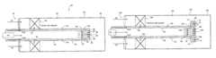
- FIG. 1is a schematic representation of a conventional premix nozzle with a diffusion tip
- FIG. 2is a schematic representation of a lean direct injection nozzle in accordance with a first exemplary but nonlimiting embodiment of the subject invention
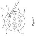
- FIG. 3is an elevation of the center body tip portion of the nozzle shown in FIG. 2 ;
- FIG. 4is a schematic representation of a lean direct injection nozzle in accordance with a second exemplary but nonlimiting embodiment.
- FIG. 5is a front elevation of the center body tip portion of the nozzle shown in FIG. 4 .
- a known DLN (dry, low NO x ) premix nozzle 10 with a diffusion tip for pilot and piloted premixis shown.
- the nozzle 10is formed with a radially outer wall 12 having an air inlet 14 and an outlet 16 .
- a center body 18extends into the nozzle and is positioned along the longitudinal center axis of the nozzle.
- the center body 18defines a fuel passage 20 that supplies some portion of fuel to a fuel premix injection ring 22 that surrounds the center body 18 and extends radially between the center body and the radially outer wall 12 of the nozzle.
- Fuelcan thus be introduced into the radially outer air passage 26 via radial fuel passage 24 , thus premixing the fuel and air upstream of the combustor reaction zone. The remaining fuel flows along passage 20 , exiting at the downstream center body tip as described in greater detail below.
- the center body 18is also provided with an inner tube 28 for supplying air to the center body tip.
- the downstream or outlet end of the center body 18has a closed-end wall or tip 30 with respective annular arrays of fuel outlet orifices 32 and air outlet orifices 34 .
- the orifices 32 , 34are angled outwardly relative to the longitudinal axis, so as to mix with the premix air flowing in the radially outer passage 26 . Note, however, that flow paths of the fuel and air exiting the orifices 32 , 34 do not intersect and thus no local intermixing of the fuel and air occurs at the center body tip.
- FIG. 2illustrates an exemplary but non-limiting embodiment of an LDI nozzle 36 in accordance with this invention.
- the nozzle 36is formed with a radially outer wall 38 (or first radially outer tube) having an air inlet 40 and an outlet 42 .
- a center body 43includes a second radially intermediate tube 44 that extends into the nozzle and is positioned along the longitudinal center axis of the nozzle.
- the tube 44defines an annular fuel passage 46 that supplies some portion of fuel to a radially oriented fuel premix injection ring 48 that surrounds the center body 43 and extends radially between the center body 43 and the radially outer wall 38 .
- Fuelis introduced into a radially outer air passage 50 via radial fuel passages 52 , for premixing fuel and air in the passage 50 upstream of the combustion chamber reaction zone. The remaining fuel flows along passage 46 to the center body tip.
- the center body 43is also provided with a third radially inner tube 54 for supplying air to the center body tip.
- Tube 54like tube 28 , lies on the center or longitudinal axis of the nozzle, i.e., the tube pairs 18 , 28 and 44 , 54 , respectively, are concentrically arranged.
- the downstream end or tip of the center body 43has a closed-end wall or tip 56 formed with relatively smaller, angled fuel outlet orifices (or passages) 58 and relatively larger coaxial air outlet orifices (or passages) 60 .
- the radially inner air tube 54has its own closed-end wall or tip 62 upstream of the end wall 56 , with tubes 64 connecting air outlet orifices 66 of the inner air tube 54 with the air outlet orifices 60 in the end wall or tip 56 .
- each air outlet orifice 60directs airflow axially away from the center body, in a downstream direction, to the nozzle outlet 42 . These air outlets could be angled tangentially if desired to impart swirl to the flow.
- Each air outlet orifice 60has its own associated set of relatively smaller fuel outlet orifices 58 , arranged at substantially diametrically opposite locations, the number and orientation set to maximize mixing while maintaining the desired fuel side pressure drop.
- each set of fuel outlet orifices 58 associated with a particular air outlet orifice 60is arranged such that axes of the fuel outlet passages 58 intersect the center axis of the associated air outlet passage 60 .
- each outlet flow of air via passages 60 at the tip 56 of the nozzle center body 44is impinged upon, i.e., intersected, by fuel flows coming from diametrically opposed passages or orifices 58 .
- This arrangementprovides more rapid mixing of fuel and air at the center body tip 56 than in current diffusion-tip nozzles, and also better mixing with the premixed air and fuel in the air passage 50 to further reduce NO x .
- the fuel outlet orificescould also be recessed some distance into the air orifices to provide some additional premixing.
- FIGS. 4 and 5illustrate a variation of the nozzle configuration shown in FIGS. 3 and 4 .
- similar reference numeralsbut with the prefix “1” added, are employed in FIGS. 4 and 5 to refer to corresponding mechanical parts.
- Specific component parts not mentioned belowcan be assumed to be similar in both structure and operation to corresponding components shown and described in connection with FIGS. 2 and 3 .
- the closed end wall or tip 156 of the center body 143is essentially radially extended beyond the center body by means of a ring 68 applied about the tip 156 of the center body outer tube 144 .
- the extended portion or ring 68is provided with plural, axially oriented air through-passages 70 that extend parallel to the center body 143 and are in communication with the radially outer air passage 150 of the nozzle. These air passages could be angled tangentially if desired to impart swirl to the flow.
- Plural fuel tubes/passages 72extend radially outwardly from the center body fuel passage 146 into the ring 68 , thus supplying fuel to plural angularly oriented (and relatively smaller diameter) fuel passages 74 .
- the passages 74are arranged to establish fuel flow paths that intersect the airflow through passages 70 so as to extend the local mixing of air and fuel beyond the diameter of the center body.
- each air passage 70has a set of associated fuel passages 74 at diametrically opposed locations, angled inwardly to intersect the air flow, the number and orientation set to maximize mixing while maintaining the desired fuel side pressure drop.
- the fuel outlet orificescould also be recessed some distance into the air orifices to provide some additional premixing.
- both the fuel and air passagesmay vary. It will be appreciated that in this example, some of the premix air in the passage 150 is diverted to supply the LDI center body 143 , further reducing NO by allowing a leaner flame at the center body tip.
- the exemplary implementations of the invention described hereinmay have beneficial results in terms of reduced NO x , increased fuel flexibility and turndown capability, as well as additional flame stability/reduced dynamics.
Landscapes
- Engineering & Computer Science (AREA)
- Chemical & Material Sciences (AREA)
- Combustion & Propulsion (AREA)
- Mechanical Engineering (AREA)
- General Engineering & Computer Science (AREA)
Abstract
Description
Claims (12)
Priority Applications (4)
| Application Number | Priority Date | Filing Date | Title |
|---|---|---|---|
| US12/222,423US8240150B2 (en) | 2008-08-08 | 2008-08-08 | Lean direct injection diffusion tip and related method |
| CN200910159567ACN101644435A (en) | 2008-08-08 | 2009-06-08 | Lean direct injection diffusion tip and related method |
| DE102009025934ADE102009025934A1 (en) | 2008-08-08 | 2009-06-08 | Diffusion tip for lean direct injection and associated method |
| JP2009136885AJP2010048542A (en) | 2008-08-08 | 2009-06-08 | Lean direct injection diffusion chip and related method |
Applications Claiming Priority (1)
| Application Number | Priority Date | Filing Date | Title |
|---|---|---|---|
| US12/222,423US8240150B2 (en) | 2008-08-08 | 2008-08-08 | Lean direct injection diffusion tip and related method |
Publications (2)
| Publication Number | Publication Date |
|---|---|
| US20100031661A1 US20100031661A1 (en) | 2010-02-11 |
| US8240150B2true US8240150B2 (en) | 2012-08-14 |
Family
ID=41501463
Family Applications (1)
| Application Number | Title | Priority Date | Filing Date |
|---|---|---|---|
| US12/222,423Expired - Fee RelatedUS8240150B2 (en) | 2008-08-08 | 2008-08-08 | Lean direct injection diffusion tip and related method |
Country Status (4)
| Country | Link |
|---|---|
| US (1) | US8240150B2 (en) |
| JP (1) | JP2010048542A (en) |
| CN (1) | CN101644435A (en) |
| DE (1) | DE102009025934A1 (en) |
Cited By (16)
| Publication number | Priority date | Publication date | Assignee | Title |
|---|---|---|---|---|
| US20110016871A1 (en)* | 2009-07-23 | 2011-01-27 | General Electric Company | Gas turbine premixing systems |
| US20110300491A1 (en)* | 2010-06-08 | 2011-12-08 | Wasif Samer P | Utilizing a diluent to lower combustion instabilities in a gas turbine engine |
| US20130040254A1 (en)* | 2011-08-08 | 2013-02-14 | General Electric Company | System and method for monitoring a combustor |
| US20140150445A1 (en)* | 2012-11-02 | 2014-06-05 | Exxonmobil Upstream Research Company | System and method for load control with diffusion combustion in a stoichiometric exhaust gas recirculation gas turbine system |
| US20140157788A1 (en)* | 2012-12-06 | 2014-06-12 | General Electric Company | Fuel nozzle for gas turbine |
| US20150276226A1 (en)* | 2014-03-28 | 2015-10-01 | Siemens Energy, Inc. | Dual outlet nozzle for a secondary fuel stage of a combustor of a gas turbine engine |
| US9714767B2 (en) | 2014-11-26 | 2017-07-25 | General Electric Company | Premix fuel nozzle assembly |
| US9803867B2 (en) | 2015-04-21 | 2017-10-31 | General Electric Company | Premix pilot nozzle |
| US9976522B2 (en) | 2016-04-15 | 2018-05-22 | Solar Turbines Incorporated | Fuel injector for combustion engine and staged fuel delivery method |
| US9982892B2 (en) | 2015-04-16 | 2018-05-29 | General Electric Company | Fuel nozzle assembly including a pilot nozzle |
| US10030869B2 (en) | 2014-11-26 | 2018-07-24 | General Electric Company | Premix fuel nozzle assembly |
| US10072848B2 (en) | 2013-12-11 | 2018-09-11 | General Electric Company | Fuel injector with premix pilot nozzle |
| US10234142B2 (en) | 2016-04-15 | 2019-03-19 | Solar Turbines Incorporated | Fuel delivery methods in combustion engine using wide range of gaseous fuels |
| US10247155B2 (en) | 2016-04-15 | 2019-04-02 | Solar Turbines Incorporated | Fuel injector and fuel system for combustion engine |
| US10330320B2 (en) | 2013-10-24 | 2019-06-25 | United Technologies Corporation | Circumferentially and axially staged annular combustor for gas turbine engine |
| US10330321B2 (en) | 2013-10-24 | 2019-06-25 | United Technologies Corporation | Circumferentially and axially staged can combustor for gas turbine engine |
Families Citing this family (28)
| Publication number | Priority date | Publication date | Assignee | Title |
|---|---|---|---|---|
| US8919673B2 (en)* | 2010-04-14 | 2014-12-30 | General Electric Company | Apparatus and method for a fuel nozzle |
| US8261555B2 (en)* | 2010-07-08 | 2012-09-11 | General Electric Company | Injection nozzle for a turbomachine |
| US9557050B2 (en) | 2010-07-30 | 2017-01-31 | General Electric Company | Fuel nozzle and assembly and gas turbine comprising the same |
| US8522556B2 (en) | 2010-12-06 | 2013-09-03 | General Electric Company | Air-staged diffusion nozzle |
| US8528338B2 (en) | 2010-12-06 | 2013-09-10 | General Electric Company | Method for operating an air-staged diffusion nozzle |
| US9360219B2 (en) | 2010-12-30 | 2016-06-07 | Rolls-Royce North American Technologies, Inc. | Supercritical or mixed phase multi-port fuel injector |
| RU2011115528A (en) | 2011-04-21 | 2012-10-27 | Дженерал Электрик Компани (US) | FUEL INJECTOR, COMBUSTION CHAMBER AND METHOD OF OPERATION OF THE COMBUSTION CHAMBER |
| US20130122436A1 (en)* | 2011-11-11 | 2013-05-16 | General Electric Company | Combustor and method for supplying fuel to a combustor |
| DE102012002664A1 (en)* | 2012-02-10 | 2013-08-14 | Rolls-Royce Deutschland Ltd & Co Kg | Gasturbinenvormischbrenner |
| US8943833B2 (en)* | 2012-07-06 | 2015-02-03 | United Technologies Corporation | Fuel flexible fuel injector |
| US10161312B2 (en) | 2012-11-02 | 2018-12-25 | General Electric Company | System and method for diffusion combustion with fuel-diluent mixing in a stoichiometric exhaust gas recirculation gas turbine system |
| TWI602986B (en)* | 2012-11-02 | 2017-10-21 | 艾克頌美孚上游研究公司 | System and method for load control with diffusion combustion in a stoichiometric exhaust gas recirculation gas turbine system |
| US11015809B2 (en)* | 2014-12-30 | 2021-05-25 | General Electric Company | Pilot nozzle in gas turbine combustor |
| CN104566474B (en)* | 2014-12-30 | 2018-02-06 | 北京华清燃气轮机与煤气化联合循环工程技术有限公司 | A kind of fuel-air mixer and gas turbine |
| US20170058784A1 (en)* | 2015-08-27 | 2017-03-02 | General Electric Company | System and method for maintaining emissions compliance while operating a gas turbine at turndown condition |
| US20170248318A1 (en)* | 2016-02-26 | 2017-08-31 | General Electric Company | Pilot nozzles in gas turbine combustors |
| CN107806647A (en)* | 2017-11-15 | 2018-03-16 | 中国科学院工程热物理研究所 | A kind of premix of gas-turbine combustion chamber nozzle on duty |
| CN111503634B (en)* | 2019-01-30 | 2024-08-06 | 美一蓝技术公司 | Ultra-low-fire tube boiler burners without high excess air and/or external flue gas recirculation |
| CN109990308A (en)* | 2019-04-28 | 2019-07-09 | 新奥能源动力科技(上海)有限公司 | A combustion chamber and gas turbine |
| EP3978807A3 (en)* | 2020-09-30 | 2022-07-06 | Rolls-Royce plc | Direct fuel injection system |
| CN114517920B (en)* | 2020-11-19 | 2023-08-08 | 中国航发商用航空发动机有限责任公司 | Injection device, combustion chamber head, combustion chamber and aeroengine |
| CN112944395B (en)* | 2021-05-12 | 2021-09-07 | 成都中科翼能科技有限公司 | Combined premixer for gas turbine |
| CN113983496B (en)* | 2021-09-23 | 2022-11-22 | 中国联合重型燃气轮机技术有限公司 | Nozzle, combustion chamber and gas turbine |
| EP4614070A3 (en) | 2021-12-21 | 2025-10-01 | General Electric Company | Gas turbine engine |
| US11725819B2 (en)* | 2021-12-21 | 2023-08-15 | General Electric Company | Gas turbine fuel nozzle having a fuel passage within a swirler |
| CN114688559A (en)* | 2022-02-17 | 2022-07-01 | 中国航发沈阳发动机研究所 | High-efficiency mixing head structure of low-emission hydrogen fuel combustion chamber |
| GB202305347D0 (en)* | 2023-04-12 | 2023-05-24 | Rolls Royce Plc | Fuel injector |
| US12339006B1 (en)* | 2023-12-22 | 2025-06-24 | General Electric Company | Turbine engine having a combustion section with a fuel nozzle assembly |
Citations (40)
| Publication number | Priority date | Publication date | Assignee | Title |
|---|---|---|---|---|
| US3980233A (en)* | 1974-10-07 | 1976-09-14 | Parker-Hannifin Corporation | Air-atomizing fuel nozzle |
| US5174504A (en)* | 1989-04-12 | 1992-12-29 | Fuel Systems Textron, Inc. | Airblast fuel injector |
| US5490389A (en)* | 1991-06-07 | 1996-02-13 | Rolls-Royce Plc | Combustor having enhanced weak extinction characteristics for a gas turbine engine |
| US5505045A (en)* | 1992-11-09 | 1996-04-09 | Fuel Systems Textron, Inc. | Fuel injector assembly with first and second fuel injectors and inner, outer, and intermediate air discharge chambers |
| US5511375A (en)* | 1994-09-12 | 1996-04-30 | General Electric Company | Dual fuel mixer for gas turbine combustor |
| US5685139A (en) | 1996-03-29 | 1997-11-11 | General Electric Company | Diffusion-premix nozzle for a gas turbine combustor and related method |
| US5701732A (en)* | 1995-01-24 | 1997-12-30 | Delavan Inc. | Method and apparatus for purging of gas turbine injectors |
| US5761907A (en)* | 1995-12-11 | 1998-06-09 | Parker-Hannifin Corporation | Thermal gradient dispersing heatshield assembly |
| US5826429A (en) | 1995-12-22 | 1998-10-27 | General Electric Co. | Catalytic combustor with lean direct injection of gas fuel for low emissions combustion and methods of operation |
| US6047550A (en) | 1996-05-02 | 2000-04-11 | General Electric Co. | Premixing dry low NOx emissions combustor with lean direct injection of gas fuel |
| US6073436A (en)* | 1997-04-30 | 2000-06-13 | Rolls-Royce Plc | Fuel injector with purge passage |
| US6076356A (en)* | 1996-03-13 | 2000-06-20 | Parker-Hannifin Corporation | Internally heatshielded nozzle |
| US6622488B2 (en)* | 2001-03-21 | 2003-09-23 | Parker-Hannifin Corporation | Pure airblast nozzle |
| US6698207B1 (en) | 2002-09-11 | 2004-03-02 | Siemens Westinghouse Power Corporation | Flame-holding, single-mode nozzle assembly with tip cooling |
| US6772594B2 (en) | 2001-06-29 | 2004-08-10 | Mitsubishi Heavy Industries, Ltd. | Gas turbine combustor |
| US6786046B2 (en) | 2002-09-11 | 2004-09-07 | Siemens Westinghouse Power Corporation | Dual-mode nozzle assembly with passive tip cooling |
| US6848260B2 (en) | 2002-09-23 | 2005-02-01 | Siemens Westinghouse Power Corporation | Premixed pilot burner for a combustion turbine engine |
| US6868676B1 (en) | 2002-12-20 | 2005-03-22 | General Electric Company | Turbine containing system and an injector therefor |
| US20050188703A1 (en) | 2004-02-26 | 2005-09-01 | Sprouse Kenneth M. | Non-swirl dry low nox (dln) combustor |
| US6945051B2 (en) | 2001-11-09 | 2005-09-20 | Enel Produzione S.P.A. | Low NOx emission diffusion flame combustor for gas turbines |
| US6968692B2 (en) | 2002-04-26 | 2005-11-29 | Rolls-Royce Corporation | Fuel premixing module for gas turbine engine combustor |
| US6996991B2 (en) | 2003-08-15 | 2006-02-14 | Siemens Westinghouse Power Corporation | Fuel injection system for a turbine engine |
| US7117679B2 (en)* | 2003-08-08 | 2006-10-10 | Rolls-Royce Plc | Fuel injection |
| US7137258B2 (en) | 2004-06-03 | 2006-11-21 | General Electric Company | Swirler configurations for combustor nozzles and related method |
| US7185494B2 (en) | 2004-04-12 | 2007-03-06 | General Electric Company | Reduced center burner in multi-burner combustor and method for operating the combustor |
| US20070089425A1 (en) | 2005-10-24 | 2007-04-26 | General Electric Company | Methods and systems for low emission gas turbine energy generation |
| US7284378B2 (en) | 2004-06-04 | 2007-10-23 | General Electric Company | Methods and apparatus for low emission gas turbine energy generation |
| US20080078160A1 (en) | 2006-10-02 | 2008-04-03 | Gilbert O Kraemer | Method and apparatus for operating a turbine engine |
| US7412833B2 (en)* | 2004-06-03 | 2008-08-19 | General Electric Company | Method of cooling centerbody of premixing burner |
| US7506496B2 (en)* | 2004-09-23 | 2009-03-24 | Snecma | Effervescent aerodynamic system for injecting an air/fuel mixture into a turbomachine combustion chamber |
| US7540154B2 (en)* | 2005-08-11 | 2009-06-02 | Mitsubishi Heavy Industries, Ltd. | Gas turbine combustor |
| US7546735B2 (en)* | 2004-10-14 | 2009-06-16 | General Electric Company | Low-cost dual-fuel combustor and related method |
| US7658074B2 (en)* | 2006-08-31 | 2010-02-09 | United Technologies Corporation | Mid-mount centerbody heat shield for turbine engine fuel nozzle |
| US7661269B2 (en)* | 2003-07-25 | 2010-02-16 | Ansaldo Energia S.P.A. | Gas turbine burner |
| US7694521B2 (en)* | 2004-03-03 | 2010-04-13 | Mitsubishi Heavy Industries, Ltd. | Installation structure of pilot nozzle of combustor |
| US7779636B2 (en)* | 2005-05-04 | 2010-08-24 | Delavan Inc | Lean direct injection atomizer for gas turbine engines |
| US7921650B2 (en)* | 2005-12-13 | 2011-04-12 | Kawasaki Jukogyo Kabushiki Kaisha | Fuel spraying apparatus of gas turbine engine |
| US8015816B2 (en)* | 2008-06-16 | 2011-09-13 | Delavan Inc | Apparatus for discouraging fuel from entering the heat shield air cavity of a fuel injector |
| US8015815B2 (en)* | 2007-04-18 | 2011-09-13 | Parker-Hannifin Corporation | Fuel injector nozzles, with labyrinth grooves, for gas turbine engines |
| US8104284B2 (en)* | 2007-04-26 | 2012-01-31 | Hitachi, Ltd. | Combustor and a fuel supply method for the combustor |
Family Cites Families (7)
| Publication number | Priority date | Publication date | Assignee | Title |
|---|---|---|---|---|
| EP0488556B1 (en)* | 1990-11-27 | 1997-07-16 | General Electric Company | Premixed secondary fuel nozzle with integral swirler |
| JP3958158B2 (en)* | 2002-09-11 | 2007-08-15 | 三菱重工業株式会社 | Combustor |
| US6802178B2 (en)* | 2002-09-12 | 2004-10-12 | The Boeing Company | Fluid injection and injection method |
| US6968695B2 (en)* | 2002-09-13 | 2005-11-29 | The Boeing Company | Compact lightweight ramjet engines incorporating swirl augmented combustion with improved performance |
| JP3826196B2 (en)* | 2003-09-30 | 2006-09-27 | 独立行政法人 宇宙航空研究開発機構 | Pre-filmer type air blast atomization nozzle |
| JP2006300448A (en)* | 2005-04-22 | 2006-11-02 | Mitsubishi Heavy Ind Ltd | Combustor for gas turbine |
| CN100483029C (en)* | 2006-01-12 | 2009-04-29 | 中国科学院工程热物理研究所 | Combustion chamber of miniature gas turbine with double premixed channel using natural gas |
- 2008
- 2008-08-08USUS12/222,423patent/US8240150B2/ennot_activeExpired - Fee Related
- 2009
- 2009-06-08DEDE102009025934Apatent/DE102009025934A1/ennot_activeWithdrawn
- 2009-06-08JPJP2009136885Apatent/JP2010048542A/enactivePending
- 2009-06-08CNCN200910159567Apatent/CN101644435A/enactivePending
Patent Citations (43)
| Publication number | Priority date | Publication date | Assignee | Title |
|---|---|---|---|---|
| US3980233A (en)* | 1974-10-07 | 1976-09-14 | Parker-Hannifin Corporation | Air-atomizing fuel nozzle |
| US5174504A (en)* | 1989-04-12 | 1992-12-29 | Fuel Systems Textron, Inc. | Airblast fuel injector |
| US5490389A (en)* | 1991-06-07 | 1996-02-13 | Rolls-Royce Plc | Combustor having enhanced weak extinction characteristics for a gas turbine engine |
| US5505045A (en)* | 1992-11-09 | 1996-04-09 | Fuel Systems Textron, Inc. | Fuel injector assembly with first and second fuel injectors and inner, outer, and intermediate air discharge chambers |
| US5511375A (en)* | 1994-09-12 | 1996-04-30 | General Electric Company | Dual fuel mixer for gas turbine combustor |
| US5701732A (en)* | 1995-01-24 | 1997-12-30 | Delavan Inc. | Method and apparatus for purging of gas turbine injectors |
| US5761907A (en)* | 1995-12-11 | 1998-06-09 | Parker-Hannifin Corporation | Thermal gradient dispersing heatshield assembly |
| US5850731A (en) | 1995-12-22 | 1998-12-22 | General Electric Co. | Catalytic combustor with lean direct injection of gas fuel for low emissions combustion and methods of operation |
| US5826429A (en) | 1995-12-22 | 1998-10-27 | General Electric Co. | Catalytic combustor with lean direct injection of gas fuel for low emissions combustion and methods of operation |
| US6076356A (en)* | 1996-03-13 | 2000-06-20 | Parker-Hannifin Corporation | Internally heatshielded nozzle |
| US5685139A (en) | 1996-03-29 | 1997-11-11 | General Electric Company | Diffusion-premix nozzle for a gas turbine combustor and related method |
| US6047550A (en) | 1996-05-02 | 2000-04-11 | General Electric Co. | Premixing dry low NOx emissions combustor with lean direct injection of gas fuel |
| US6192688B1 (en) | 1996-05-02 | 2001-02-27 | General Electric Co. | Premixing dry low nox emissions combustor with lean direct injection of gas fule |
| US6073436A (en)* | 1997-04-30 | 2000-06-13 | Rolls-Royce Plc | Fuel injector with purge passage |
| US6622488B2 (en)* | 2001-03-21 | 2003-09-23 | Parker-Hannifin Corporation | Pure airblast nozzle |
| US6772594B2 (en) | 2001-06-29 | 2004-08-10 | Mitsubishi Heavy Industries, Ltd. | Gas turbine combustor |
| US6945051B2 (en) | 2001-11-09 | 2005-09-20 | Enel Produzione S.P.A. | Low NOx emission diffusion flame combustor for gas turbines |
| US6968692B2 (en) | 2002-04-26 | 2005-11-29 | Rolls-Royce Corporation | Fuel premixing module for gas turbine engine combustor |
| US6698207B1 (en) | 2002-09-11 | 2004-03-02 | Siemens Westinghouse Power Corporation | Flame-holding, single-mode nozzle assembly with tip cooling |
| US6786046B2 (en) | 2002-09-11 | 2004-09-07 | Siemens Westinghouse Power Corporation | Dual-mode nozzle assembly with passive tip cooling |
| US6848260B2 (en) | 2002-09-23 | 2005-02-01 | Siemens Westinghouse Power Corporation | Premixed pilot burner for a combustion turbine engine |
| US6868676B1 (en) | 2002-12-20 | 2005-03-22 | General Electric Company | Turbine containing system and an injector therefor |
| US7661269B2 (en)* | 2003-07-25 | 2010-02-16 | Ansaldo Energia S.P.A. | Gas turbine burner |
| US7117679B2 (en)* | 2003-08-08 | 2006-10-10 | Rolls-Royce Plc | Fuel injection |
| US6996991B2 (en) | 2003-08-15 | 2006-02-14 | Siemens Westinghouse Power Corporation | Fuel injection system for a turbine engine |
| US20050188703A1 (en) | 2004-02-26 | 2005-09-01 | Sprouse Kenneth M. | Non-swirl dry low nox (dln) combustor |
| US7127899B2 (en) | 2004-02-26 | 2006-10-31 | United Technologies Corporation | Non-swirl dry low NOx (DLN) combustor |
| US7694521B2 (en)* | 2004-03-03 | 2010-04-13 | Mitsubishi Heavy Industries, Ltd. | Installation structure of pilot nozzle of combustor |
| US7185494B2 (en) | 2004-04-12 | 2007-03-06 | General Electric Company | Reduced center burner in multi-burner combustor and method for operating the combustor |
| US7137258B2 (en) | 2004-06-03 | 2006-11-21 | General Electric Company | Swirler configurations for combustor nozzles and related method |
| US7412833B2 (en)* | 2004-06-03 | 2008-08-19 | General Electric Company | Method of cooling centerbody of premixing burner |
| US7284378B2 (en) | 2004-06-04 | 2007-10-23 | General Electric Company | Methods and apparatus for low emission gas turbine energy generation |
| US7506496B2 (en)* | 2004-09-23 | 2009-03-24 | Snecma | Effervescent aerodynamic system for injecting an air/fuel mixture into a turbomachine combustion chamber |
| US7546735B2 (en)* | 2004-10-14 | 2009-06-16 | General Electric Company | Low-cost dual-fuel combustor and related method |
| US7779636B2 (en)* | 2005-05-04 | 2010-08-24 | Delavan Inc | Lean direct injection atomizer for gas turbine engines |
| US7540154B2 (en)* | 2005-08-11 | 2009-06-02 | Mitsubishi Heavy Industries, Ltd. | Gas turbine combustor |
| US20070089425A1 (en) | 2005-10-24 | 2007-04-26 | General Electric Company | Methods and systems for low emission gas turbine energy generation |
| US7921650B2 (en)* | 2005-12-13 | 2011-04-12 | Kawasaki Jukogyo Kabushiki Kaisha | Fuel spraying apparatus of gas turbine engine |
| US7658074B2 (en)* | 2006-08-31 | 2010-02-09 | United Technologies Corporation | Mid-mount centerbody heat shield for turbine engine fuel nozzle |
| US20080078160A1 (en) | 2006-10-02 | 2008-04-03 | Gilbert O Kraemer | Method and apparatus for operating a turbine engine |
| US8015815B2 (en)* | 2007-04-18 | 2011-09-13 | Parker-Hannifin Corporation | Fuel injector nozzles, with labyrinth grooves, for gas turbine engines |
| US8104284B2 (en)* | 2007-04-26 | 2012-01-31 | Hitachi, Ltd. | Combustor and a fuel supply method for the combustor |
| US8015816B2 (en)* | 2008-06-16 | 2011-09-13 | Delavan Inc | Apparatus for discouraging fuel from entering the heat shield air cavity of a fuel injector |
Cited By (20)
| Publication number | Priority date | Publication date | Assignee | Title |
|---|---|---|---|---|
| US8616002B2 (en) | 2009-07-23 | 2013-12-31 | General Electric Company | Gas turbine premixing systems |
| US20110016871A1 (en)* | 2009-07-23 | 2011-01-27 | General Electric Company | Gas turbine premixing systems |
| US20110300491A1 (en)* | 2010-06-08 | 2011-12-08 | Wasif Samer P | Utilizing a diluent to lower combustion instabilities in a gas turbine engine |
| US9017064B2 (en)* | 2010-06-08 | 2015-04-28 | Siemens Energy, Inc. | Utilizing a diluent to lower combustion instabilities in a gas turbine engine |
| US20130040254A1 (en)* | 2011-08-08 | 2013-02-14 | General Electric Company | System and method for monitoring a combustor |
| US10215412B2 (en)* | 2012-11-02 | 2019-02-26 | General Electric Company | System and method for load control with diffusion combustion in a stoichiometric exhaust gas recirculation gas turbine system |
| US20140150445A1 (en)* | 2012-11-02 | 2014-06-05 | Exxonmobil Upstream Research Company | System and method for load control with diffusion combustion in a stoichiometric exhaust gas recirculation gas turbine system |
| US20140157788A1 (en)* | 2012-12-06 | 2014-06-12 | General Electric Company | Fuel nozzle for gas turbine |
| US10330320B2 (en) | 2013-10-24 | 2019-06-25 | United Technologies Corporation | Circumferentially and axially staged annular combustor for gas turbine engine |
| US10330321B2 (en) | 2013-10-24 | 2019-06-25 | United Technologies Corporation | Circumferentially and axially staged can combustor for gas turbine engine |
| US10072848B2 (en) | 2013-12-11 | 2018-09-11 | General Electric Company | Fuel injector with premix pilot nozzle |
| US10139111B2 (en)* | 2014-03-28 | 2018-11-27 | Siemens Energy, Inc. | Dual outlet nozzle for a secondary fuel stage of a combustor of a gas turbine engine |
| US20150276226A1 (en)* | 2014-03-28 | 2015-10-01 | Siemens Energy, Inc. | Dual outlet nozzle for a secondary fuel stage of a combustor of a gas turbine engine |
| US9714767B2 (en) | 2014-11-26 | 2017-07-25 | General Electric Company | Premix fuel nozzle assembly |
| US10030869B2 (en) | 2014-11-26 | 2018-07-24 | General Electric Company | Premix fuel nozzle assembly |
| US9982892B2 (en) | 2015-04-16 | 2018-05-29 | General Electric Company | Fuel nozzle assembly including a pilot nozzle |
| US9803867B2 (en) | 2015-04-21 | 2017-10-31 | General Electric Company | Premix pilot nozzle |
| US9976522B2 (en) | 2016-04-15 | 2018-05-22 | Solar Turbines Incorporated | Fuel injector for combustion engine and staged fuel delivery method |
| US10234142B2 (en) | 2016-04-15 | 2019-03-19 | Solar Turbines Incorporated | Fuel delivery methods in combustion engine using wide range of gaseous fuels |
| US10247155B2 (en) | 2016-04-15 | 2019-04-02 | Solar Turbines Incorporated | Fuel injector and fuel system for combustion engine |
Also Published As
| Publication number | Publication date |
|---|---|
| CN101644435A (en) | 2010-02-10 |
| DE102009025934A1 (en) | 2010-02-11 |
| US20100031661A1 (en) | 2010-02-11 |
| JP2010048542A (en) | 2010-03-04 |
Similar Documents
| Publication | Publication Date | Title |
|---|---|---|
| US8240150B2 (en) | Lean direct injection diffusion tip and related method | |
| EP3679300B1 (en) | Gas turbine combustor assembly with a trapped vortex feature and method of operating a gas turbine combustor | |
| US10480791B2 (en) | Fuel injector to facilitate reduced NOx emissions in a combustor system | |
| US6047550A (en) | Premixing dry low NOx emissions combustor with lean direct injection of gas fuel | |
| US8113001B2 (en) | Tubular fuel injector for secondary fuel nozzle | |
| EP0936406B1 (en) | Burner with uniform fuel/air premixing for low emissions combustion | |
| US5596873A (en) | Gas turbine combustor with a plurality of circumferentially spaced pre-mixers | |
| US8464537B2 (en) | Fuel nozzle for combustor | |
| EP1543272B1 (en) | Turbine engine fuel nozzle | |
| US7886991B2 (en) | Premixed direct injection nozzle | |
| US8959921B2 (en) | Flame tolerant secondary fuel nozzle | |
| US20100319353A1 (en) | Multiple Fuel Circuits for Syngas/NG DLN in a Premixed Nozzle | |
| CN101793408B (en) | Combustor nozzle | |
| US5826429A (en) | Catalytic combustor with lean direct injection of gas fuel for low emissions combustion and methods of operation | |
| EP1985927B1 (en) | Gas turbine combustor system with lean-direct injection for reducing NOx emissions | |
| US8677760B2 (en) | Fuel nozzle with integrated passages and method of operation | |
| US20100192581A1 (en) | Premixed direct injection nozzle | |
| EP2551598B1 (en) | Method of operating a turbomachine | |
| US20090056336A1 (en) | Gas turbine premixer with radially staged flow passages and method for mixing air and gas in a gas turbine | |
| KR20100069683A (en) | Apparatus and method for controlling the secondary injection of fuel | |
| US20010049932A1 (en) | Premixing dry low NOx emissions combustor with lean direct injection of gas fuel | |
| US20190003713A1 (en) | Air-shielded fuel injection assembly to facilitate reduced nox emissions in a combustor system | |
| JP2010019542A (en) | Pre-mixing apparatus for turbine engine | |
| JP6466102B2 (en) | Dual fuel combustor for gas turbine engines | |
| EP4056902B1 (en) | Fuel mixer |
Legal Events
| Date | Code | Title | Description |
|---|---|---|---|
| AS | Assignment | Owner name:GENERAL ELECTRIC COMPANY,NEW YORK Free format text:ASSIGNMENT OF ASSIGNORS INTEREST;ASSIGNORS:VARATHARAJAN, BALACHANDAR;ZIMINSKY, WILLY S.;LIPINSKI, JOHN;AND OTHERS;SIGNING DATES FROM 20080801 TO 20080806;REEL/FRAME:021415/0381 Owner name:GENERAL ELECTRIC COMPANY, NEW YORK Free format text:ASSIGNMENT OF ASSIGNORS INTEREST;ASSIGNORS:VARATHARAJAN, BALACHANDAR;ZIMINSKY, WILLY S.;LIPINSKI, JOHN;AND OTHERS;SIGNING DATES FROM 20080801 TO 20080806;REEL/FRAME:021415/0381 | |
| FEPP | Fee payment procedure | Free format text:PAYOR NUMBER ASSIGNED (ORIGINAL EVENT CODE: ASPN); ENTITY STATUS OF PATENT OWNER: LARGE ENTITY | |
| ZAAA | Notice of allowance and fees due | Free format text:ORIGINAL CODE: NOA | |
| ZAAB | Notice of allowance mailed | Free format text:ORIGINAL CODE: MN/=. | |
| STCF | Information on status: patent grant | Free format text:PATENTED CASE | |
| FPAY | Fee payment | Year of fee payment:4 | |
| MAFP | Maintenance fee payment | Free format text:PAYMENT OF MAINTENANCE FEE, 8TH YEAR, LARGE ENTITY (ORIGINAL EVENT CODE: M1552); ENTITY STATUS OF PATENT OWNER: LARGE ENTITY Year of fee payment:8 | |
| AS | Assignment | Owner name:UNITED STATES DEPARTMENT OF ENERGY, DISTRICT OF COLUMBIA Free format text:CONFIRMATORY LICENSE;ASSIGNOR:GE POWER AND WATER;REEL/FRAME:064481/0305 Effective date:20081030 | |
| FEPP | Fee payment procedure | Free format text:MAINTENANCE FEE REMINDER MAILED (ORIGINAL EVENT CODE: REM.); ENTITY STATUS OF PATENT OWNER: LARGE ENTITY | |
| LAPS | Lapse for failure to pay maintenance fees | Free format text:PATENT EXPIRED FOR FAILURE TO PAY MAINTENANCE FEES (ORIGINAL EVENT CODE: EXP.); ENTITY STATUS OF PATENT OWNER: LARGE ENTITY | |
| STCH | Information on status: patent discontinuation | Free format text:PATENT EXPIRED DUE TO NONPAYMENT OF MAINTENANCE FEES UNDER 37 CFR 1.362 | |
| FP | Lapsed due to failure to pay maintenance fee | Effective date:20240814 |