US8240109B2 - Support system for solar panels - Google Patents
Support system for solar panelsDownload PDFInfo
- Publication number
- US8240109B2 US8240109B2US12/567,908US56790809AUS8240109B2US 8240109 B2US8240109 B2US 8240109B2US 56790809 AUS56790809 AUS 56790809AUS 8240109 B2US8240109 B2US 8240109B2
- Authority
- US
- United States
- Prior art keywords
- panel
- support
- rails
- upper panel
- joists
- Prior art date
- Legal status (The legal status is an assumption and is not a legal conclusion. Google has not performed a legal analysis and makes no representation as to the accuracy of the status listed.)
- Active, expires
Links
- 238000009434installationMethods0.000claimsabstractdescription29
- 239000000758substrateSubstances0.000claimsabstractdescription5
- 238000000034methodMethods0.000claimsdescription25
- 125000006850spacer groupChemical group0.000claimsdescription7
- 238000005259measurementMethods0.000claimsdescription6
- 238000007373indentationMethods0.000claims2
- 238000009432framingMethods0.000description11
- 239000004677NylonSubstances0.000description9
- 239000000463materialSubstances0.000description9
- 229920001778nylonPolymers0.000description9
- 230000008901benefitEffects0.000description6
- 238000000926separation methodMethods0.000description6
- 230000005484gravityEffects0.000description3
- 238000004519manufacturing processMethods0.000description3
- 239000004709Chlorinated polyethyleneSubstances0.000description2
- 229920002943EPDM rubberPolymers0.000description2
- 230000000295complement effectEffects0.000description2
- 229910052751metalInorganic materials0.000description2
- 239000002184metalSubstances0.000description2
- 230000002093peripheral effectEffects0.000description2
- 229920001343polytetrafluoroethylenePolymers0.000description2
- 239000004810polytetrafluoroethyleneSubstances0.000description2
- 229920000544Gore-TexPolymers0.000description1
- 229910000831SteelInorganic materials0.000description1
- 229920006362Teflon®Polymers0.000description1
- 230000004308accommodationEffects0.000description1
- 239000000853adhesiveSubstances0.000description1
- 230000001070adhesive effectEffects0.000description1
- 229910052782aluminiumInorganic materials0.000description1
- XAGFODPZIPBFFR-UHFFFAOYSA-NaluminiumChemical compound[Al]XAGFODPZIPBFFR-UHFFFAOYSA-N0.000description1
- 238000003491arrayMethods0.000description1
- 229920005549butyl rubberPolymers0.000description1
- 239000006227byproductSubstances0.000description1
- 230000015556catabolic processEffects0.000description1
- 230000006835compressionEffects0.000description1
- 238000007906compressionMethods0.000description1
- 230000008602contractionEffects0.000description1
- 238000006731degradation reactionMethods0.000description1
- 238000005553drillingMethods0.000description1
- 230000009977dual effectEffects0.000description1
- 229920001971elastomerPolymers0.000description1
- 230000005611electricityEffects0.000description1
- 230000007613environmental effectEffects0.000description1
- 238000001125extrusionMethods0.000description1
- 230000003993interactionEffects0.000description1
- 229920001084poly(chloroprene)Polymers0.000description1
- -1polytetrafluoroethylenePolymers0.000description1
- 238000003908quality control methodMethods0.000description1
- 230000002787reinforcementEffects0.000description1
- 239000010959steelSubstances0.000description1
Images


Classifications
- H—ELECTRICITY
- H02—GENERATION; CONVERSION OR DISTRIBUTION OF ELECTRIC POWER
- H02S—GENERATION OF ELECTRIC POWER BY CONVERSION OF INFRARED RADIATION, VISIBLE LIGHT OR ULTRAVIOLET LIGHT, e.g. USING PHOTOVOLTAIC [PV] MODULES
- H02S20/00—Supporting structures for PV modules
- H02S20/30—Supporting structures being movable or adjustable, e.g. for angle adjustment
- F—MECHANICAL ENGINEERING; LIGHTING; HEATING; WEAPONS; BLASTING
- F24—HEATING; RANGES; VENTILATING
- F24S—SOLAR HEAT COLLECTORS; SOLAR HEAT SYSTEMS
- F24S25/00—Arrangement of stationary mountings or supports for solar heat collector modules
- F24S25/10—Arrangement of stationary mountings or supports for solar heat collector modules extending in directions away from a supporting surface
- F24S25/12—Arrangement of stationary mountings or supports for solar heat collector modules extending in directions away from a supporting surface using posts in combination with upper profiles
- F—MECHANICAL ENGINEERING; LIGHTING; HEATING; WEAPONS; BLASTING
- F24—HEATING; RANGES; VENTILATING
- F24S—SOLAR HEAT COLLECTORS; SOLAR HEAT SYSTEMS
- F24S25/00—Arrangement of stationary mountings or supports for solar heat collector modules
- F24S25/60—Fixation means, e.g. fasteners, specially adapted for supporting solar heat collector modules
- F24S25/63—Fixation means, e.g. fasteners, specially adapted for supporting solar heat collector modules for fixing modules or their peripheral frames to supporting elements
- F—MECHANICAL ENGINEERING; LIGHTING; HEATING; WEAPONS; BLASTING
- F24—HEATING; RANGES; VENTILATING
- F24S—SOLAR HEAT COLLECTORS; SOLAR HEAT SYSTEMS
- F24S25/00—Arrangement of stationary mountings or supports for solar heat collector modules
- F24S25/60—Fixation means, e.g. fasteners, specially adapted for supporting solar heat collector modules
- F24S25/65—Fixation means, e.g. fasteners, specially adapted for supporting solar heat collector modules for coupling adjacent supporting elements, e.g. for connecting profiles together
- F—MECHANICAL ENGINEERING; LIGHTING; HEATING; WEAPONS; BLASTING
- F24—HEATING; RANGES; VENTILATING
- F24S—SOLAR HEAT COLLECTORS; SOLAR HEAT SYSTEMS
- F24S80/00—Details, accessories or component parts of solar heat collectors not provided for in groups F24S10/00-F24S70/00
- F24S80/70—Sealing means
- H—ELECTRICITY
- H02—GENERATION; CONVERSION OR DISTRIBUTION OF ELECTRIC POWER
- H02S—GENERATION OF ELECTRIC POWER BY CONVERSION OF INFRARED RADIATION, VISIBLE LIGHT OR ULTRAVIOLET LIGHT, e.g. USING PHOTOVOLTAIC [PV] MODULES
- H02S20/00—Supporting structures for PV modules
- H02S20/10—Supporting structures directly fixed to the ground
- H—ELECTRICITY
- H02—GENERATION; CONVERSION OR DISTRIBUTION OF ELECTRIC POWER
- H02S—GENERATION OF ELECTRIC POWER BY CONVERSION OF INFRARED RADIATION, VISIBLE LIGHT OR ULTRAVIOLET LIGHT, e.g. USING PHOTOVOLTAIC [PV] MODULES
- H02S20/00—Supporting structures for PV modules
- H02S20/20—Supporting structures directly fixed to an immovable object
- H02S20/22—Supporting structures directly fixed to an immovable object specially adapted for buildings
- H02S20/23—Supporting structures directly fixed to an immovable object specially adapted for buildings specially adapted for roof structures
- F—MECHANICAL ENGINEERING; LIGHTING; HEATING; WEAPONS; BLASTING
- F24—HEATING; RANGES; VENTILATING
- F24S—SOLAR HEAT COLLECTORS; SOLAR HEAT SYSTEMS
- F24S25/00—Arrangement of stationary mountings or supports for solar heat collector modules
- F24S2025/01—Special support components; Methods of use
- F24S2025/012—Foldable support elements
- F—MECHANICAL ENGINEERING; LIGHTING; HEATING; WEAPONS; BLASTING
- F24—HEATING; RANGES; VENTILATING
- F24S—SOLAR HEAT COLLECTORS; SOLAR HEAT SYSTEMS
- F24S25/00—Arrangement of stationary mountings or supports for solar heat collector modules
- F24S2025/01—Special support components; Methods of use
- F24S2025/014—Methods for installing support elements
- F—MECHANICAL ENGINEERING; LIGHTING; HEATING; WEAPONS; BLASTING
- F24—HEATING; RANGES; VENTILATING
- F24S—SOLAR HEAT COLLECTORS; SOLAR HEAT SYSTEMS
- F24S25/00—Arrangement of stationary mountings or supports for solar heat collector modules
- F24S2025/80—Special profiles
- F24S2025/801—Special profiles having hollow parts with closed cross-section
- Y—GENERAL TAGGING OF NEW TECHNOLOGICAL DEVELOPMENTS; GENERAL TAGGING OF CROSS-SECTIONAL TECHNOLOGIES SPANNING OVER SEVERAL SECTIONS OF THE IPC; TECHNICAL SUBJECTS COVERED BY FORMER USPC CROSS-REFERENCE ART COLLECTIONS [XRACs] AND DIGESTS
- Y02—TECHNOLOGIES OR APPLICATIONS FOR MITIGATION OR ADAPTATION AGAINST CLIMATE CHANGE
- Y02B—CLIMATE CHANGE MITIGATION TECHNOLOGIES RELATED TO BUILDINGS, e.g. HOUSING, HOUSE APPLIANCES OR RELATED END-USER APPLICATIONS
- Y02B10/00—Integration of renewable energy sources in buildings
- Y02B10/10—Photovoltaic [PV]
- Y—GENERAL TAGGING OF NEW TECHNOLOGICAL DEVELOPMENTS; GENERAL TAGGING OF CROSS-SECTIONAL TECHNOLOGIES SPANNING OVER SEVERAL SECTIONS OF THE IPC; TECHNICAL SUBJECTS COVERED BY FORMER USPC CROSS-REFERENCE ART COLLECTIONS [XRACs] AND DIGESTS
- Y02—TECHNOLOGIES OR APPLICATIONS FOR MITIGATION OR ADAPTATION AGAINST CLIMATE CHANGE
- Y02E—REDUCTION OF GREENHOUSE GAS [GHG] EMISSIONS, RELATED TO ENERGY GENERATION, TRANSMISSION OR DISTRIBUTION
- Y02E10/00—Energy generation through renewable energy sources
- Y02E10/40—Solar thermal energy, e.g. solar towers
- Y02E10/47—Mountings or tracking
- Y—GENERAL TAGGING OF NEW TECHNOLOGICAL DEVELOPMENTS; GENERAL TAGGING OF CROSS-SECTIONAL TECHNOLOGIES SPANNING OVER SEVERAL SECTIONS OF THE IPC; TECHNICAL SUBJECTS COVERED BY FORMER USPC CROSS-REFERENCE ART COLLECTIONS [XRACs] AND DIGESTS
- Y02—TECHNOLOGIES OR APPLICATIONS FOR MITIGATION OR ADAPTATION AGAINST CLIMATE CHANGE
- Y02E—REDUCTION OF GREENHOUSE GAS [GHG] EMISSIONS, RELATED TO ENERGY GENERATION, TRANSMISSION OR DISTRIBUTION
- Y02E10/00—Energy generation through renewable energy sources
- Y02E10/50—Photovoltaic [PV] energy
- Y—GENERAL TAGGING OF NEW TECHNOLOGICAL DEVELOPMENTS; GENERAL TAGGING OF CROSS-SECTIONAL TECHNOLOGIES SPANNING OVER SEVERAL SECTIONS OF THE IPC; TECHNICAL SUBJECTS COVERED BY FORMER USPC CROSS-REFERENCE ART COLLECTIONS [XRACs] AND DIGESTS
- Y10—TECHNICAL SUBJECTS COVERED BY FORMER USPC
- Y10T—TECHNICAL SUBJECTS COVERED BY FORMER US CLASSIFICATION
- Y10T29/00—Metal working
- Y10T29/49—Method of mechanical manufacture
- Y10T29/49616—Structural member making
Definitions
- This inventionrelates to a solar energy collection system, and more particularly to a support system for an array of photovoltaic panels and method of assembling the same.
- the inventionincludes a bi-directional span of support members, including a profiled support rail having a longitudinal T-slot channel adapted to receive the head of a bolt for adjustable attachment to a support joist.
- a variety of panel-holding devices, such as friction clips,may also be used.
- a standard photovoltaic panel arrayincludes a plurality of solar panels optimally arranged for converting light incident upon the panels to electricity.
- Various support systemsare used for attachment to roofs, free-field ground racks or tracking units. Typically, these support systems are costly, labor intensive to install, heavy, structurally inferior and mechanically complicated.
- a support systemgenerally includes off-the-shelf metal framing channels having a C-shaped cross-section, such as those sold under the trademarks UNISTRUTTM or BLIMETM, improvised for use as vertical and horizontal support members.
- the photovoltaic panelsare directly secured to the support members and held in place by clips.
- the clipsserve as hold-down devices to secure the panel against the corresponding top support member in spaced-relationship.
- the clipsare positioned and attached about the panel edges once each panel is arranged in place.
- support elementssuch as I-beams
- Tilt bracketsare installed at the top of each I-beam, and each tilt bracket is secured to the I-beam such that a tilt bracket flange extends above the I-beam at an angle as best seen in FIG. 2A .
- two UNISTRUTTM joistsspan the tilt brackets and are secured thereto.
- UNISTRUTTM railsare positioned across and fastened to the horizontal joists.
- a bolt through a bolt hole made in the rail sidewallattaches to a threaded opening in a transverse nut-like plate slideably mounted inside the channel of the UNISTRUTTM joist, so that the nut-like plate engages and tightly secures against the upper flange of the joist's C-channel as seen in FIG. 2A .
- the width of the plateis slightly less than the width of the channel, so that the plate can be slideably adjusted in the channel, without the plate rotating therein.
- each solar panelis positioned and top and bottom clips are secured to each rail about the perimeter of each panel, to hold the panel such that the center of each panel is between two rails.
- FIG. 1Another example of a support system is shown in U.S. Pat. No. 5,762,720, issued to Hanoka et al., which describes various mounting brackets used with a UNISTRUTTM channel.
- the Hanoka et al. patentuses a solar cell module having an integral mounting structure, i.e. a mounting bracket bonded directly to a surface of the backskin layer of a laminated solar cell module, which is then secured to the channel bracket by bolt or slidably engaging C-shaped members.
- Other examplesare shown in U.S. Pat. No. 6,617,507, issued to Mapes et al., U.S. Pat. No. 6,370,828, issued to Genschorek, U.S. Pat. No. 4,966,631, issued to Matlin et al., and U.S. Pat. No. 7,012,188, issued to Erling.
- spacing of the photovoltaic panelsis important to accommodate expansion and contraction due to the change of the weather. It is important, therefore, that the panels are properly spaced for maximum use of the bi-directional area of the span. Different spacing may be required on account of different temperature swings within various geographical areas. It is difficult, however, to precisely space the panels on-site using existing support structures without advanced technical assistance. For example, with the existing design described above (with reference to FIGS. 2A and 2B ), until the rails are tightly secured to the horizontal joist, each rail is free to slide along the horizontal joists and, therefore, will need to be properly spaced and secured once mounted on-site.
- the distance between the two horizontal joistsis fixed on account of the drilled bolt holes through the rails, it is preferred to drill the holes on-site, so that the horizontal joists can be aligned to attach through the pre-drilled attachment holes of the tilt bracket.
- the operation of drilling the holes on-siterequires skilled workers, and even with skilled installation, might still result in misalignment of the support structure and/or the solar panels supported by that structure.
- an improved support systemwould achieve a precise configuration in the field without extensive work at the installation site.
- the use of such an improved systemwould facilitate easy placement of solar panels onto the support structure.
- a variety of different panel clips or holderscould be used within the overall concept of the system.
- the shipping configuration of the improved support systemwould be such so as to be easily handled in transit while still facilitating rapid deployment.
- none of the conventional artoffers these capabilities.
- a method of assembling a support structure constituted by a bi-directional array of structural members installed in a configuration of substantially perpendicular upper and lower structural membersincludes the steps of identifying characteristics of the installed configuration of the support structure, including relevant measurements of the support structure with respect to the installation site. Then the support structure is assembled in accordance with the characteristics of the installed configuration at a staging site. Once properly assembled, the support structure is collapsed into an interconnected package appropriate for transport. After transport to the installation site, the support structure is installed according to the predetermined characteristics of the configuration as it is to be installed at the installation site.
- a collapsible support systemconstituted by an intersecting array of structural members including a first group of lower support joists and a second group of upper support rails. These structural members are held together by adjustable connectors that facilitate rotation of the support joist and the upper support rails. Also, with this system a plurality of unique holding clips may be used to easily receive and hold each solar panel by the collapsible support structure when the collapsible structure is in its assembled and installed state.
- FIG. 1is a perspective view of an assembled conventional field ground rack support system for securing a plurality of solar panels
- FIG. 2Ais a side view of a conventional tilt bracket mount with prior art C-shaped sectional channels secured back-to-back to form support joists to which upper support rails, also shown in FIG. 2B , are secured;
- FIG. 2Bshows an end view of prior art upper support rails, each with a C-shaped sectional channel
- FIG. 3is a perspective view of a support system of the instant invention showing solar panels arranged in a column and in spaced relationship thereon wherein the support system has horizontally-aligned support joists and (relative thereto) vertically-aligned upper support rails;
- FIG. 4Ais a top plan view of the bi-directional span of the assembly of the instant invention in the open position showing vertically-aligned upper support rails attached atop horizontally-aligned support joists;
- FIG. 4Bis an end elevational view of the bi-directional span of the assembly shown in FIG. 4A ;
- FIG. 5Ais a top plan view illustrating the bi-directional span of the assembly shown in FIG. 4A in the folded position
- FIG. 5Bshows in enlarged detail the support system of the instant invention in a collapsed or folded position, and depicting, in particular, a connector for holding the support joist to a support and/or tilt bracket or similar structure held, i.e. pinched between adjacent support rails;
- FIG. 5Cis a side view of FIG. 5B depicting the connector for holding the support joist to the support and/or tilt bracket or similar structure;
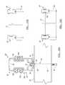
- FIG. 6is a side elevation and partial sectional view that depicts a support joist and a tubular upper support rail with a single-panel clip;
- FIG. 7is an end elevation and partial sectional view perpendicular to that shown in FIG. 6 ;
- FIG. 8is a cross-sectional perspective view of an upper support rail
- FIG. 9is an end view of the upper support rail of FIG. 8 ;
- FIG. 10is a sectional elevation view showing a solar panel mounted between a two-panel clip and a single-panel clip
- FIG. 11is a sectional elevation view showing a panel being fitted within a gasket of the two-panel clip and arranged to be fitted into a single-panel clip gasket;
- FIG. 12is a sectional elevation view showing a panel fitted within the gasket of the two-panel clip, having rearmost retaining ribs, a fulcrum ridge and a saw-tooth profile;
- FIG. 13Ais a top plan view of the bi-directional span of the assembly of the instant invention in the open position showing upper support rails attached atop support joists;
- FIG. 13Bis an end elevational view of the bi-directional span of the assembly shown in FIG. 13A ;
- FIG. 14is a top plan view illustrating the bi-directional span of the assembly shown in FIG. 13A in the folded position
- FIG. 15is a side elevation and partial sectional view that shows a support joist and a tubular upper support rail with a two-panel clip;
- FIG. 16is a perspective view of the support system similar to FIG. 3 , but in this case using vertically-aligned support joists and horizontally-aligned support rails;
- FIG. 17is an end view of the a second embodiment of an I-shaped tubular upper support rail
- FIG. 18Ais a cross-section of the second embodiment of the upper support rail with panel framing clips
- FIGS. 18B and 18Care partial sectional views showing a framed and unframed panel, respectively, fitted within pockets of adjacently spaced I-shaped tubular upper support rails;
- FIGS. 19A and 19Bare perspective and cross-sectional views, respectively, of a panel-framing clip used with unframed panels.
- FIG. 20is a partial perspective view of the support system of the instant invention depicting unframed solar panels arranged in a column and in spaced relationship thereon, wherein the support system has longituding, I-shaped tubular upper support rails.
- a support system for a photovoltaic array of framed or unframed solar panels 12 , 12 ′, respectively, known in the prior artincludes a free ground rack structure having spaced vertical support elements 14 extending from the ground.
- the support system 10 of FIG. 1shows only two vertical support elements 14 , although multiple support elements may be used to accommodate a longer array of solar panels.
- the support systemcan also be mounted to a roof (or other structure), or tracking unit.
- Each of the support elements 14 for the free-field ground rackis preferably an I-beam securely embedded and vertically aligned in the ground, as is well known in the art.
- a pair of lower horizontally-aligned, C-shaped support joists 11 , 13is mounted at the upper ends of the support elements 14 by tilt bracket mounts 16 .
- the vertical support elements 14are spanned by the support joists 11 , 13 .
- the joists 11 , 13can be longitudinally extended to span all of the support elements 14 in one, unbroken length.
- FIG. 2Aillustrates conventional support joists 11 , 13 secured to tilt bracket mounts 16 by back-to-back channels 17 , 18 , with each channel having a C-shaped cross-section.
- each conventional upper rail 15is secured to the lower support joists 11 , 13 by bolts through a corresponding wall of its C-channel 19 , as best seen in FIG. 2B .
- FIG. 3depicts a support system 10 for a photovoltaic array of solar panels 12 , attached to the same, conventional vertical support elements 14 .
- the support system 10in this case, however, includes a bi-directional span of horizontally-aligned lower support joists 20 and vertically-aligned upper support rails 30 - 1 through 30 - n , as also seen in FIGS. 4A and 4B .
- the terminology “horizontally-aligned”refers to structural members that appear to be parallel to the horizon. “Vertically-aligned” structural members are perpendicular to the “horizontally-aligned” structural members. However, because the present invention can be mounted on almost any structural support, the terms “horizontally-aligned” and “vertically-aligned” may become inappropriate for certain situations. Accordingly, alternative terminology such as, “longitudinally extending” or “laterally extending” can be used instead. For example, in FIG. 3 , the “horizontally-aligned” structural members are also extended longitudinally while the “vertically-aligned” members extend in a lateral direction. These various terminologies are used as a matter of convenience, and for purposes of example only.
- the bi-directional spancan have the lower support joists 20 to align along the length of tilting support brackets 16 .
- upper support rails 30 - 1 through 30 - nextended longitudinally, as seen in FIGS. 13A , 13 B and 16 .
- the present inventioncan be adjusted to conform to any support structure or any “footprint” available for the deployment of solar panels, or any other, panel-like structure to be supported by the present invention.
- each upper support rail 30 - n in this designis a hollow aluminum extrusion.
- the upper support railmay be made of roll-formed steel.
- each support rail 30 - nhas a tubular body 31 having a generally rectangular cross-section with an upper wall section 36 and lower wall section 32 defined between spaced side walls 35 as best seen in FIGS. 8 and 9 .
- the upper wall section 36has a flat top surface 37 and upper wall of varied thickness, preferably having its thickest portion 38 in the center. This thicker center portion 38 is for added strength when fastening the single-panel clips 100 , 100 ′ and two-panel clip 120 (described below). Strength can also be achieved for each support rail 30 - n using a thicker lower wall section 32 .
- the lower wall section 32includes a longitudinal T-slot sectional channel 33 and, preferably, a longitudinal C-slot sectional channel 34 .
- an alternative (i.e. second) profile of the support rail 30 ′-n shown in FIGS. 17 , 18 A, 18 B and 18 Ccan be used.
- This profilehas an I-shaped cross-sectional tubular body 31 ′ with a flanged upper wall section 36 ′ and a flanged lower wall section 32 ′ forming a pocket 39 therebetween. More specifically, spaced side walls 35 ′ form pockets 39 with the flanged upper and lower wall sections 36 ′, 32 ′, respectively.
- the preferred upper support rail design described abovei.e.
- the upper wall section 36 ′ of the alternative designhas a flat top surface 37 and upper wall of varied thickness, preferably having its thickest portion 38 in the center.
- the lower wall section 32 ′includes a longitudinal T-slot sectional channel 33 between two longitudinal C-slot sectional channels 34 ; one on each side of the T-slot channel.
- the dual C-slot sectional channels 34 in the second support rail 30 ′-nallows for easier assembly, in that wires can be tucked away on either side of the rail.
- the pockets 39may be used to eliminate clips 100 , 100 ′, and/or 120 (described in detail below), i.e. to secure individual solar panels 12 (framed) or 12 ′ (unframed) by sliding the panels therein between adjacent rails 30 ′, as best seen in FIGS. 18B , 18 C and 20 .
- Pockets 39are especially important in that they can be configured to allow the panel (whether framed or unframed) to move therethrough along the length. This capability allows panels or panel-like structures to be slid along the lengths of the upper support rails 30 , thereby facilitating a quick and accurate installation of the panels supported by the inventive structural support system.
- the quick and accurate installation of the solar panelsis one of the byproducts, and is a benefit coextensive with those of the present invention. With the present invention, accuracy is not sacrificed for ease of installation.
- each upper support rail 30 or 30 ′is governed by the height of the individual solar panels 12 , 12 ′ and the number of solar panels per column.
- the spacing between each upper support rail 30 or 30 ′is governed by the width of the individual solar panels 12 , and the number of solar panels per row.
- Each upper support rail 30 - 1 through 30 - n or 30 ′- 1 through 30 ′-nis attached to the lower support joists 20 by bolts 40 , wherein the head 42 of each bolt is slidably accommodated in the corresponding T-slot channel 33 of the respective upper support rail.
- the shank 43 of the bolt 40passes through and is secured to the respective support joist 20 using a nut 45 or other type fastener to form the bi-directional span.
- each support joist 20is separated from the corresponding upper support rail 30 - n or 30 ′-n by nonconductive separation washers 24 , preferably made of nylon, in order to prevent galvanic interaction between unlike materials.
- the nylon washer 24is preferably about 1 ⁇ 8 th inch thick, although other materials and thicknesses may be used.
- the use of the nylon washer 24 at the intersection of support joist 20 and a corresponding upper support rail 30facilitates the rotation of these two elements with respect to each other. Rotation is further facilitated if the nut 45 includes a nylon insert. The nylon insert helps to prevent the nut 45 from loosening during folding and unfolding of the bi-directional span.
- FIGS. 6 and 7show the alignment of the holding clip 100 attached to upper support rail 30 - n , with the length of panel 12 , 12 ′ perpendicular the length of support rail 30 , as best seen in FIG. 3 .
- FIG. 15shows the alignment of the holding clip attached to an upper support rail 30 - n , with the length of panel 12 , 12 ′ parallel to the length of support rail 30 , best seen in FIG. 16 .
- upper support rail 30 or 30 ′can also secure framed and unframed panels 12 , 12 ′, respectively, in pockets 39 (i.e. using framing clips 150 in the case of unframed panels 12 ′).
- panel holding clips 100 , 100 ′ and 120 ′as shown in FIGS. 3 , 10 , 11 , 12 and 16 , at least two types of panel holding clips are preferably used, i.e. end or single-panel clips 100 , 100 ′ and an intermediate or two-panel clip 120 .
- the panel holding clips 100 , 100 ′, 120encompass a wide variety of devices that hold or grip panel-like structures using a number of different methods. One is simple gravity. Another is the tightness of or pressure applied by the arms of the gasket encompassing a portion of the panel-like structure. More specifically, the gasket 130 , 131 lining the clip can create spring-like pressure through deformation of the material.
- One examplewould be rubber or nylon teeth (described below and identified as teeth 140 and 153 in FIGS. 10 , 11 , and 12 , as well as FIGS. 18A , 19 A and 19 B for panel framing clips 150 , respectively).
- Yet another way to grip the panelis through an adhesive material used with the gasket 130 , 131 , to develop a bond with the portions of the panel-like structure being held.
- the gaskets used with holding clips 100 , 100 ′, 120 and/or framing clips 150can be easily changed as needed, depending upon the position of the support structure 10 , and the configuration of the panels 12 , 12 ′ supported thereby.
- the single-panel holding clips 100 , 100 ′have a generally Z-shaped profile with a base portion 110 and first wall 112 .
- Holding clip 100has a first flange 114 and uses an unfulcrumed U-shaped gasket 130 .
- Clip 100 ′has a first flange and gasket that substantially match that of flange 124 and gasket 131 described in detail below with reference to the two-panel holding clip 120 .
- the two-panel holding clip 120is generally U-shaped having a first extended flange 114 , a second extended flange 124 , a first wall 112 , second wall 122 and a base portion 110 , and uses two different gaskets 130 , 131 .
- both gaskets 130 , 131have a U-shaped cross-section with a fold 138 , upper and lower contact surfaces, 132 , 134 , respectively, with a plurality of ribs 140 , i.e. saw-tooth profiles, and a back wall 136 .
- the fulcrumed U-shaped clip gasket 131preferably includes resilient, rearmost retaining ribs 142 , designed to contact a top peripheral side 143 of the panel 12 , 12 ′ to push and hold the panel downward into the clip below.
- retaining rib 142may extend from the back wall 136 , in which case the retaining rib 142 may be replaced with a spring to provide resiliency.
- the lower contact surface 134 of the fulcrumed gasket 131further includes a fulcrum point 144 , i.e. an extended elongated ridge, which forces against the solar panel 12 . 12 ′ toward the upper contact surface 132 and second clip flange 124 .
- a fulcrum point 144i.e. an extended elongated ridge
- the bottom portion of the two-panel holding clip 120holds the top peripheral edge of the solar panel 12 , 12 ′ therebelow, aligned with the other solar panels in the respective column of panels.
- the bottom portion of the holding clip 120includes a second clip flange 124 , which is longer than the opposing first clip flange 114 , which holds the bottom of an uppermost solar panel 12 , 12 ′ in the same column.
- the top or first clip flange 114 of the two-panel holding clip 120is preferably the same length as that of the flange of the bottom mounted single-panel holding clip 100 , i.e. having the same U-shaped unfulcrumed clip gasket 130 used therewith.
- the length of longer clip flange 124is at least twice the length of the shorter first flange 114 , so that the solar panel 12 , 12 ′ can be inserted first under flange 124 , pivoted on fulcrum point 144 and then inserted under flange 114 , whereby flanges 114 , 124 , gravity, and the resiliency, pressure and friction of the gaskets 130 , 131 , as described, hold the panel 12 , 12 ′ firmly in place once set in position.
- single-panel holding clips 100 and 100 ′The difference between single-panel holding clips 100 and 100 ′ is that clip 100 ′ is the first clip at the top of each upper support rail 30 - n or 30 ′-n; while holding clip 100 is the last clip, i.e. at the bottom of each support rail 30 - n or 30 ′-n. Since the single-panel holding clip 100 ′ is the top clip of each upper support rail, it has a fulcrumed U-shaped gasket, identical to the fulcrumed gasket 131 , to accommodate its extended flange profile (identical to flange 124 ).
- the profile of holding clip 100 ′substantially matches that of the bottom portion of the two-panel holding clip 120 to fit and secure the top perimeter edge of each solar panel therein.
- Both of the clip gaskets 130 , 131preferably include a T-shaped engagement protuberance 137 for slidable registration and attachment via a complementary, somewhat T-shaped retaining groove 117 formed between the walls 112 , 122 and their respective flanges 114 , 124 .
- Gaskets 130 , 131are used with each holding clip 100 , 100 ′, 120 to protect the front and back edges 143 of each solar panel 12 .
- Each gasket 130 , 132is preferably extruded with the T-shaped mounting protuberance 137 .
- the gaskets or clip liners 130 , 131are made of a material which is physically and chemically stable, and preferably electrically nonconductive. Furthermore, the gaskets 130 , 131 should be of an electrically-resistant material and have good elasticity upon compression. Suitable materials, which can be employed include, but are not limited to, neoprene, butyl rubber, ethylene-propylene diene monomer (EPDM), chlorinated polyethylene (CPE) and a polytetrafluoroethylene (PTFE) material such as GORTEX® (a trademark of W. L. Gore & Associates, Inc.), or TEFLON® (a trademark of E.I. DuPont de Nemours & Company).
- EPDMethylene-propylene diene monomer
- CPEchlorinated polyethylene
- PTFEpolytetrafluoroethylene
- longitudinal pockets 39 of rails 30 ′can be used as an alternative method for conveniently securing panels 30 , 30 ′ to the bi-directional span 10 .
- each panelcan be inserted and slid in place along the longitudinal pockets 39 of adjacent rails 30 ′ as best seen in FIG. 18B (for framed panels 12 ) and 18 C (for unframed panels 12 ′).
- panels 12 , 12 ′are slid in place and stacked in columns using the joist and rail orientation shown in FIG.
- panels 12 , 12 ′may be aligned in rows using the joist and rail orientation shown in FIG. 13A .
- Caps and/or extended finger stopsare used at the end of the rails 30 ′ to secure the panels within the corresponding columns or rows.
- each framing clip 150preferably includes a framing clip bracket 154 fitted with a gasket 152 (engaged via bracket flange 155 and gasket groove 156 ), as best seen in FIGS. 19A and 19B .
- the gasket 152further includes ribs 153 much like those of ribs 140 (discussed above with reference to panel holding clips 100 , 100 ′ and 120 ).
- Spacers 159are preferably used to maintain appropriate spacing between adjacent panels in columns or rows, as shown, for example, in FIG. 20 .
- the spacers 159can be constituted by a structure similar to double-sided holding clips 120 without the base portion 110 for bolt attachment. However, any other type of appropriate structure can be used.
- the spacersare important since the movement permitted by the holding clips 100 , 100 ′, and 120 or by movement in longitudinal pockets 39 may permit solar panels 12 , 12 ′ to become misaligned with respect to each other.
- the support system 10 of this inventionallows for off-site assembly (at a convenient staging site) to precise engineering specifications, in that, once the support members are assembled, the bi-directional span can be folded or collapsed on itself, as shown with reference to FIGS. 5 and 14 , and then easily transported to the installation site.
- the support system 10is then positioned, and secured to the roof, rack, tracking unit, or other substrate via the tilt bracket 16 (or equivalent structure) while still in the folded position. More specifically, after attaching one support joist 20 to one of the brackets 16 , using a pair of tilt bracket attachment bolts 240 (wedged between adjacent rails 30 - 2 and 30 - 3 in the folded position, as shown in FIGS.
- the method of assembling the inventive support system 10 for an array of photovoltaic panels 12 , 12 ′ in columns and rowsincludes the steps of building the bi-directional span by attaching support members, i.e. support joists 20 and upper support rails 30 - n or 30 ′-n, using a plurality of attachment bolts 40 and nuts 45 .
- the top surface 37 of each upper support rail 30 - n or 30 ′-nmust be unobstructed for the solar panels 12 , 12 ′ to be secure against.
- each upper support rail 30 - n or 30 ′-nhas a substantial rectangular cross-section portion or an I-shaped cross-section portion, respectively.
- upper support rail 30 , 30 ′has an upper wall section 36 , 36 ′ and lower wall section 32 , 32 ′.
- each individual support system 10can be easily engineered, fabricated, assembled and adjusted to various specifications.
- the longitudinal T-shaped sectional channel 33 in the lower wall section 32 , 32 ′is adapted to adjustably receive the heads 42 of attachment bolts 40 .
- Bolts 40attach each upper support rail 30 - n , 30 ′-n passing through one of the lower support joists 20 .
- the T-shaped slotted channel 33permits the bolt 40 to be placed at any location along the length of the channel and through the lower support joist 20 as shown in FIGS. 6 and 7 (for a first orientation of the support joist assembly) and FIG. 15 (for the second orientation of the support joist assembly).
- FIG. 18Acan be considered to show attachment of rails 30 ′ to joist 20 in either orientation.
- each clipcan be pre-positioned and attached to the upper wall section 36 , 36 ′ of the upper support rails 30 , 30 ′, respectively, by a self-threading bolt 145 secured to the thick portion 38 and whose head engages the base portion 110 of the holding clip.
- the perimeter holding clips 100 , 100 ′, and 120can be positioned and attached to the upper wall section 36 , 36 ′ of the upper support rails 30 , 30 ′ off-site to adhere to the proper engineering specifications for a specific installation.
- the positioning and necessary spacing for the columns and rows of the photovoltaic panels 12 , 12 ′ of the arraycan be optimally and easily made off-site during fabrication and assembly, without wasting space, time and materials.
- the bi-directional span of the support system 10can be reduced in size by folding the upper support rails 30 relative to the support joists 20 .
- the folded spancan be easily shipped to the location for installation, then unfolded and secured to the roof, free-field ground rack, tracking unit, or other substrate for attachment of the photovoltaic panels 12 , 12 ′ via the pre-positioned, attached and properly spaced perimeter holding clips 100 , 100 ′, 120 (as shown in FIGS. 3 and 16 ) or framing clips 150 and spacers 160 (shown in FIGS. 18B , 18 C and 20 ).
- One preferred method to assemble the bi-directional span 10 horizontal support joists 20is to align a first support joist 20 over tilt support bracket(s) 16 (or similar support structures), and to bolt the support joist 20 to the support bracket(s) 16 using bolts 240 secured within the folded structure, as shown in FIGS. 5B and 5C and previously discussed.
- the aligned support joist 20will be attached first to one or two brackets. Connection is made to the tilt support bracket(s) 16 before anything else is done.
- the bi-directional support structure 10is unfolded sufficiently to allow a second support joist to be laid over the tilting support bracket(s) 16 so that the connection process can be repeated. It is important that the support joist 20 be provided with slots 216 (as depicted in FIGS. 3 , 4 A, 5 B and/or 14 ) in order to facilitate on-site adjustment. It is preferred that all of the routed or punched slots 216 be carefully made during the pre-installation operation before a support structure 10 is shipped to the permanent installation site. The alignment in which support joists 20 are laid across two or more tilt support brackets 16 is that depicted in FIGS. 3 and 16 . Once two support joists 20 are attached to their respective tilt brackets 16 (or similar structures), then the entirety of the bi-directional support structure 10 is ready for permanent attachment of the panels 12 , 12 ′.
- This important advantage of pre-engineering, fabrication and assembly conducted off-site at a plant or other convenient fabrication areaincludes the precise measurements needed to place and drill or punch the connection holes 44 for proper alignment of the lower support joist 20 and upper support rails 30 , 30 ′. More specifically, with reference to the joist-to-rail orientation shown in FIG. 4A , in the assembly process the support joists 20 are aligned to the position at which they will be connected to the tilt bracket 16 in the field.
- connectionsare made between the first support joist 20 and the first upper support rail 30 , 30 ′ by inserting a bolt 40 in spaced, pre-drilled holes 44 passing through the support joist 20 with the bolt head 42 at the top of the support joist and a hex nut 45 at the bottom.
- a separation washer 24is included near each bolt head.
- the processis repeated for the other horizontal support joist(s) 20 .
- a single upper support raili.e. either 30 - 1 or 30 ′- 1 , is aligned with the head 42 of the first bolt 40 located in position along the first lower support joist 20 .
- the bolt head 42is lifted, separated from the separation washer 24 , and slid into the T-slot channel 33 in the upper support rail 30 or 30 ′. This step is then repeated for the other lower support joist(s) 20 .
- the end of the first upper support rail 30 - 1 or 30 ′- 1is then aligned with a side wall of the first lower support joist 20 , and the hex nuts 45 are torque snug to a predetermined torque value that permits rotation between joist 20 and upper rail 30 , 30 ′.
- the horizontal support joist 20is made perpendicular to the vertical support rail 30 - 1 or 30 ′- 1 .
- support rails 30may be alternately or intermittently arranged with support rails 30 ′ in the same assembly.
- the method for assembling the bi-directional span 10 having the second orientation, i.e. FIG. 13A , of support joists 20is substantially the same as that described above for support joists oriented according to FIG. 4A .
- a first lower support joist 20is aligned and bolts 40 are inserted in spaced, pre-drilled holes 44 passing through the lower support joist 20 , with the bolt head 42 at the top of the joist and a hex nut 45 at the bottom. Again, the separation washer 24 is included near each bolt head.
- the processis repeated for the second and any subsequent vertical support joists 20 .
- a single upper support rail 30i.e.
- the upper support rail 30 - 1 or 30 ′- 1is aligned perpendicular with a side wall of each lower support joist 20 ), and all hex nuts 45 are torque to a predetermined value permitting rotation of joist and rail while maintaining the precise, intersecting position therebetween.
- the other rails 30 - 2 through 30 - n or 30 ′- 2 through 30 ′-nare then assembled and secured in like fashion.
- each hex nut 45preferably includes a nylon insert.
- the nylon insertretains torque pressure of the fastener (at the predetermined value) during shipping and prevents the support rails 30 and/or 30 ′ from loosening from the support joists 20 when folded and unfolded.
- the upper rails 30 , 30 ′can pivot relative to the support joists 20 without any significant loosening.
- the assembled bi-directional spancan be folded and unfolded by grasping the ends of two adjacent support joists, and pushing one of the lower support joists 20 longitudinally away relative to the second support joist 20 , permitting the assembly to fold into a compacted form for shipping.
- the folding operationcan be made just as easily by grasping the ends of two adjacent horizontal rails 30 , 30 ′ and pushing one longitudinally away relative to the other.
- tubular body forms 31 , 31 ′, having varied wall thickness 38 , and channels 33 , 34substantially reduces the weight of the overall support rails 30 - n or 30 ′-n, and, therefore, the overall weight of the assembled system in comparison to the prior art. Yet, because of the aforementioned selective reinforcement, the structural strength is enhanced.
- the support structure 10 of the present inventionfacilitates simple and quick installation. After shipping the structure assembly 10 to the field for permanent installation, it is unpackaged, and the appropriate lower support joist 20 is aligned and secured to one or both of the vertical support elements 14 , via the bottom attachment openings in the tilt bracket mounts 16 , depending on the joist-to-rail orientation. For example, in the case of the assembly 10 having the orientation of support joists 20 as shown in FIG. 13A , either the right or left outside-most lower support joist 20 is aligned parallel, mounted and secured to the corresponding vertical support element 14 , via the tilt bracket mounts 16 .
- the other outside-most lower support joist 20is pushed to unfold and realign mutually parallel to the first support joist, i.e. perpendicular to the upper support rails 30 , 30 ′, so as to align mutually parallel to the other tilt bracket.
- the assembly 10is securely fixed via the top attachment openings 216 in the corresponding support joists 20 to the tilt bracket mounts 16 using bracket attachment bolts 240 as previously described.
- the space between the support joists 20can be adjusted (if needed) by sliding the joists along the rails via their T-slot channels, so that the spacing of the joists 20 precisely align with and attach to the tilt bracket mounts 16 .
- the spacing and perpendicular relationship of the upper support rails 30are checked relative to the side wall of the support joists 20 using a machinist square or similar setup fixture and adjusted if needed.
- the hex nuts 45are also checked to assure that they continue to be snug after shipping and installation.
- each solar panel 12 , 12 ′is fixed in place by sliding into rows or columns via the longitudinal pockets 39 (with reference to rails 30 ′) or by using top holding clips 100 , 100 ′ or 120 (i.e. inserting the top of the panel into its top holding clip 100 ′ or 120 , then pivoted about the respective gasket fulcrums 144 , to fit the panel's bottom edge into corresponding bottom gravity holding clips 100 , 120 , as best seen in FIGS. 10 through 12 ).
- wiresare tucked away in the corresponding C-shaped slotted channels 34 .
- the proper spacing between panelsis maintained by spacers 159 , as depicted in FIG. 20 .
Landscapes
- Engineering & Computer Science (AREA)
- Chemical & Material Sciences (AREA)
- Mechanical Engineering (AREA)
- Sustainable Development (AREA)
- Sustainable Energy (AREA)
- Thermal Sciences (AREA)
- Physics & Mathematics (AREA)
- Combustion & Propulsion (AREA)
- Life Sciences & Earth Sciences (AREA)
- General Engineering & Computer Science (AREA)
- Architecture (AREA)
- Civil Engineering (AREA)
- Structural Engineering (AREA)
- Photovoltaic Devices (AREA)
- Roof Covering Using Slabs Or Stiff Sheets (AREA)
Abstract
Description
Claims (17)
Priority Applications (13)
| Application Number | Priority Date | Filing Date | Title |
|---|---|---|---|
| US12/567,908US8240109B2 (en) | 2009-03-20 | 2009-09-28 | Support system for solar panels |
| PCT/US2009/005726WO2010107419A1 (en) | 2009-03-20 | 2009-10-21 | Support system for solar panels |
| CA2755214ACA2755214A1 (en) | 2009-03-20 | 2009-10-21 | Support system for solar panels |
| EP09841995AEP2408679A1 (en) | 2009-03-20 | 2009-10-21 | Support system for solar panels |
| CN2009801582172ACN102361800A (en) | 2009-03-20 | 2009-10-21 | Support system for solar panels |
| US12/686,598US8256169B2 (en) | 2009-03-20 | 2010-01-13 | Support system for solar panels |
| EP10753794AEP2409338A1 (en) | 2009-03-20 | 2010-02-23 | Support system for solar panels |
| CN2010800128946ACN102362362A (en) | 2009-03-20 | 2010-02-23 | Support system for solar panels |
| CA2755217ACA2755217C (en) | 2009-03-20 | 2010-02-23 | Support system for solar panels |
| PCT/US2010/000526WO2010107466A1 (en) | 2009-03-20 | 2010-02-23 | Support system for solar panels |
| US13/115,506US20110220596A1 (en) | 2009-03-20 | 2011-05-25 | Support system for solar panels |
| US13/533,301US8464496B2 (en) | 2009-03-20 | 2012-06-26 | Support system for solar panels |
| US14/173,005US20140151312A1 (en) | 2009-03-20 | 2014-02-05 | Support system for solar panels |
Applications Claiming Priority (2)
| Application Number | Priority Date | Filing Date | Title |
|---|---|---|---|
| US12/383,240US8316590B2 (en) | 2009-03-20 | 2009-03-20 | Support system for solar panels |
| US12/567,908US8240109B2 (en) | 2009-03-20 | 2009-09-28 | Support system for solar panels |
Related Parent Applications (1)
| Application Number | Title | Priority Date | Filing Date |
|---|---|---|---|
| US12/383,240Continuation-In-PartUS8316590B2 (en) | 2009-03-20 | 2009-03-20 | Support system for solar panels |
Related Child Applications (2)
| Application Number | Title | Priority Date | Filing Date |
|---|---|---|---|
| US12/383,240Continuation-In-PartUS8316590B2 (en) | 2009-03-20 | 2009-03-20 | Support system for solar panels |
| US12/686,598Continuation-In-PartUS8256169B2 (en) | 2009-03-20 | 2010-01-13 | Support system for solar panels |
Publications (2)
| Publication Number | Publication Date |
|---|---|
| US20100237029A1 US20100237029A1 (en) | 2010-09-23 |
| US8240109B2true US8240109B2 (en) | 2012-08-14 |
Family
ID=42736589
Family Applications (1)
| Application Number | Title | Priority Date | Filing Date |
|---|---|---|---|
| US12/567,908Active2030-04-28US8240109B2 (en) | 2009-03-20 | 2009-09-28 | Support system for solar panels |
Country Status (5)
| Country | Link |
|---|---|
| US (1) | US8240109B2 (en) |
| EP (1) | EP2408679A1 (en) |
| CN (1) | CN102361800A (en) |
| CA (1) | CA2755214A1 (en) |
| WO (1) | WO2010107419A1 (en) |
Cited By (46)
| Publication number | Priority date | Publication date | Assignee | Title |
|---|---|---|---|---|
| US20100132769A1 (en)* | 2009-10-23 | 2010-06-03 | Chevron U.S.A. Inc. | Solar canopy support system |
| US20110094559A1 (en)* | 2009-10-23 | 2011-04-28 | Chevron U.S.A. Inc. | Solar canopy support system |
| US20110204193A1 (en)* | 2008-11-05 | 2011-08-25 | Kenichi Sagayama | Solar cell module stand and solar power generation system using same |
| US20120024350A1 (en)* | 2010-08-02 | 2012-02-02 | Wuxi Suntech Power Co., Ltd. | Photovoltaic module frame and a photovoltaic module having the frame |
| US20120031471A1 (en)* | 2010-08-09 | 2012-02-09 | Du Pont Apollo Limited | Solar panel module |
| US20120085394A1 (en)* | 2010-10-06 | 2012-04-12 | Mainstream Energy Corporation | Snap-in mounting systems for laminate solar panels |
| US20120085395A1 (en)* | 2009-05-12 | 2012-04-12 | Saint-Gobain Glass France | Solar module attachment device and mounting method |
| US20120097807A1 (en)* | 2010-10-25 | 2012-04-26 | Rees Kyle J | Solar panel support system |
| US20120117895A1 (en)* | 2010-11-16 | 2012-05-17 | Du Pont Apollo Limited | Photovoltaic module installation device |
| US20120125409A1 (en)* | 2010-11-17 | 2012-05-24 | Wuerth Solar Gmbh & Co. Kg | Fastening of panel-type elements |
| US20120167364A1 (en)* | 2009-05-27 | 2012-07-05 | Schletter Gmbh | Apparatus for fastening a mounting rail to a threaded shaft |
| US20120273021A1 (en)* | 2006-08-31 | 2012-11-01 | Antaya Stephen C | Buss Bar Strip |
| US20130106191A1 (en)* | 2011-07-26 | 2013-05-02 | Claudia Iovino | Renewable mobile resource station |
| US8464496B2 (en) | 2009-03-20 | 2013-06-18 | Northern States Metals Company | Support system for solar panels |
| US20130168340A1 (en)* | 2010-06-09 | 2013-07-04 | Schletter Gmbh | Profiled support element of a row of pv modules |
| CN103452347A (en)* | 2013-09-06 | 2013-12-18 | 贵州绿卡能科技实业有限公司 | Lightning-proof, hail-proof and convenient-to-install solar hot bath combined room |
| US8650812B2 (en) | 2009-03-20 | 2014-02-18 | Northern States Metals Company | Support system for solar panels |
| US8695290B1 (en)* | 2009-12-07 | 2014-04-15 | Ironridge, Inc. | Systems and methods for splicing solar panel racks |
| US20140263902A1 (en)* | 2013-03-15 | 2014-09-18 | First Solar, Inc. | System and method for mounting photovoltaic modules |
| US8839573B2 (en) | 2011-02-11 | 2014-09-23 | Northern States Metals Company | Spring clip |
| US8938932B1 (en)* | 2013-12-13 | 2015-01-27 | Quality Product Llc | Rail-less roof mounting system |
| US20150034145A1 (en)* | 2010-05-26 | 2015-02-05 | Sanyo Electric Co., Ltd. | Support structure for double-sided power generation type solar cell panels |
| US9093583B2 (en) | 2012-09-19 | 2015-07-28 | Opterra Energy Services, Inc. | Folding solar canopy assembly |
| US9093582B2 (en) | 2012-09-19 | 2015-07-28 | Opterra Energy Services, Inc. | Solar canopy assembly |
| US9303663B2 (en) | 2013-04-11 | 2016-04-05 | Northern States Metals Company | Locking rail alignment system |
| US9568900B2 (en) | 2012-12-11 | 2017-02-14 | Opterra Energy Services, Inc. | Systems and methods for regulating an alternative energy source that is decoupled from a power grid |
| WO2017066823A1 (en)* | 2015-10-20 | 2017-04-27 | Glen Carless | A portable frame for supporting a solar panel |
| US20170250648A1 (en)* | 2016-02-25 | 2017-08-31 | Solarcity Corporation | Photovoltaic mounting system for solar tracker array |
| US9750340B2 (en) | 2015-02-11 | 2017-09-05 | Dorel Home Furnishings, Inc. | Banquet table |
| US9774293B2 (en) | 2012-09-19 | 2017-09-26 | Opterra Energy Services, Inc. | Bracing assembly |
| US10008974B2 (en) | 2011-09-02 | 2018-06-26 | Pv Solutions, Llc | Mounting system for photovoltaic arrays |
| US10326278B2 (en) | 2011-09-02 | 2019-06-18 | Pv Solutions, Llc | System for tracking and allocating renewable energy contributions to a modular renewable energy system |
| US10490682B2 (en) | 2018-03-14 | 2019-11-26 | National Mechanical Group Corp. | Frame-less encapsulated photo-voltaic solar panel supporting solar cell modules encapsulated within multiple layers of optically-transparent epoxy-resin materials |
| US10879835B2 (en) | 2015-01-28 | 2020-12-29 | Pv Solutions, Llc | Integrated electrical and mechanical photovoltaic array interconnection system |
| US11022343B2 (en) | 2011-09-02 | 2021-06-01 | Pv Solutions, Llc | Mounting system for photovoltaic arrays |
| US11050383B2 (en) | 2019-05-21 | 2021-06-29 | Nextracker Inc | Radial cam helix with 0 degree stow for solar tracker |
| US11159120B2 (en) | 2018-03-23 | 2021-10-26 | Nextracker Inc. | Multiple actuator system for solar tracker |
| US20220038044A1 (en)* | 2017-06-14 | 2022-02-03 | Thomas E. RUSSELL | Metallurgical steel post design for solar farm foundations and increased guardrail durability |
| US11387771B2 (en) | 2018-06-07 | 2022-07-12 | Nextracker Llc | Helical actuator system for solar tracker |
| US11552590B2 (en)* | 2018-10-08 | 2023-01-10 | The Board Of Regents Of The University Of Oklahoma | System for mounting solar panels |
| US11949370B2 (en) | 2020-09-14 | 2024-04-02 | Nextracker Llc | Support frames for solar trackers |
| US12184231B2 (en) | 2020-08-28 | 2024-12-31 | The Aes Corporation | Solar panel handling system |
| US12301162B2 (en) | 2021-02-18 | 2025-05-13 | Systems Pty Ltd | System for mounting one or more solar panels |
| US12334868B2 (en) | 2020-08-28 | 2025-06-17 | The Aes Corporation | Solar panel handling system |
| US12398564B2 (en) | 2021-08-16 | 2025-08-26 | Certainteed Llc | Roofing system and method of installation |
| USD1091448S1 (en) | 2023-10-10 | 2025-09-02 | Bluescope Buildings North America, Inc. | Solar panel frame bracket |
Families Citing this family (37)
| Publication number | Priority date | Publication date | Assignee | Title |
|---|---|---|---|---|
| US10277159B2 (en)* | 2008-11-17 | 2019-04-30 | Kbfx Llc | Finished multi-sensor units |
| US8240109B2 (en) | 2009-03-20 | 2012-08-14 | Northern States Metals Company | Support system for solar panels |
| CA2716517A1 (en)* | 2009-06-05 | 2010-12-05 | First Solar, Inc. | Photovoltaic module ground mount |
| US8584338B2 (en) | 2010-05-24 | 2013-11-19 | Chevron U.S.A. Inc. | Solar module array pre-assembly method |
| US8418983B2 (en) | 2010-07-29 | 2013-04-16 | First Solar, Inc. | Slider clip and photovoltaic structure mounting system |
| WO2012018360A1 (en)* | 2010-08-06 | 2012-02-09 | First Solar, Inc. | Folding mount for photovoltaic modules |
| US20120067336A1 (en)* | 2010-09-22 | 2012-03-22 | Atomic Energy Council-Institute Of Nuclear Energy Research | Device for Supporting a Sun-Tracking Unit of a Photovoltaic Module |
| DE102010050052A1 (en)* | 2010-10-29 | 2012-05-03 | Adensis Gmbh | Photovoltaic module with protective screen |
| DE102010062384A1 (en)* | 2010-12-03 | 2012-06-06 | Hilti Aktiengesellschaft | Clamp for a plate element, in particular for a photovoltaic module |
| US20120211059A1 (en)* | 2011-02-21 | 2012-08-23 | Paul Anthony Tomaso | Penetrated ground mount solar racking system |
| US20120261526A1 (en)* | 2011-04-13 | 2012-10-18 | Solon Corporation | Frame-like holder for a solar panel, with a cable holder |
| WO2013028969A1 (en)* | 2011-08-24 | 2013-02-28 | Corning Incorporated | Photovoltaic assembly comprising an array of load compensating pv modules |
| DE112012004254T5 (en)* | 2011-10-14 | 2014-10-30 | Magna International Inc. | Solar cell arrangement with a frame structure |
| US8724341B2 (en)* | 2011-11-18 | 2014-05-13 | Shenzhen China Star Optoelectronics Technology Co., Ltd. | Backplane and backlight module |
| US8726587B2 (en) | 2011-12-02 | 2014-05-20 | Cooper Technologies Company | Module rail for photovoltaic system |
| US20130139870A1 (en)* | 2011-12-02 | 2013-06-06 | Cooper Technologies Company | Pier connection sytem for pier caps of photovoltaic system |
| US8640402B1 (en)* | 2012-03-08 | 2014-02-04 | Henry H. Bilge | Building roof fascia, coping and/or solar panel connector arrangement |
| US9316417B2 (en)* | 2012-06-29 | 2016-04-19 | Sunpower Corporation | Framing system for mounting solar collecting devices |
| US9163861B2 (en) | 2012-10-01 | 2015-10-20 | Georgia Tech Research Corporation | Solar panel truss mounting systems and methods |
| CN103268894B (en)* | 2013-04-15 | 2015-10-21 | 李支柱 | A kind of drop height type component installation being applicable to solar power system |
| GB2526269B (en) | 2014-05-16 | 2018-09-12 | Solar Frame Solutions Ltd | Solar-collector roofing assembly |
| CN104617855B (en)* | 2015-01-14 | 2017-03-15 | 广西衍易新能源投资有限公司 | A kind of solar photovoltaic bracket |
| DE202015002312U1 (en)* | 2015-03-26 | 2015-04-08 | Solarworld Ag | Ramenprofilleiste for solar cell laminates, framed solar module and mounting system for solar modules |
| US12294332B2 (en) | 2015-12-15 | 2025-05-06 | Kbfx Llc | Solar carports, solar-tracking carports, and methods |
| CN105627142A (en)* | 2015-12-30 | 2016-06-01 | 中国电子科技集团公司第十八研究所 | Lamp array used for lightweight large-area solar battery array illumination test |
| CN105625645B (en)* | 2016-01-08 | 2018-06-26 | 中国建筑第八工程局有限公司 | Suspension type steel structure lighting skylight construction method |
| WO2019022684A2 (en)* | 2016-11-28 | 2019-01-31 | Eae Elektrik Asansor Endustrisi Insaat Sanayi Ve Ticaret Anonim Sirketi | A solar panel assembly |
| CN107332496B (en)* | 2017-08-02 | 2019-02-26 | 杭州金固新能源开发有限公司 | Photovoltaic module longitudinal beam structure |
| CN108390624B (en)* | 2018-03-05 | 2020-02-07 | 苏州市昌美新能源科技有限公司 | Photovoltaic system surveys device |
| US10797635B2 (en) | 2018-08-29 | 2020-10-06 | Nextracker Inc. | Solar module mounting bracket assemblies |
| CN110454997B (en)* | 2019-09-10 | 2024-06-11 | 浙江正泰新能源开发有限公司 | Photovoltaic module fast-assembling fixed knot constructs |
| WO2021178244A1 (en)* | 2020-03-02 | 2021-09-10 | Skylite Solar Inc. | Solar module racking system |
| CN111335533B (en)* | 2020-03-31 | 2021-08-13 | 上海宝冶集团有限公司 | Construction method of solar metal inclined roof of prefabricated residential building |
| CN112609917B (en)* | 2020-12-18 | 2022-05-17 | 保定嘉盛光电科技股份有限公司 | Vertical face installation mode based on photovoltaic wall brick |
| CN113221222A (en)* | 2021-05-10 | 2021-08-06 | 中国计量大学上虞高等研究院有限公司 | Method for arranging photovoltaic panels on building roof |
| CN114489158B (en)* | 2022-02-11 | 2025-04-01 | 杭州华鼎新能源有限公司 | A photovoltaic automatic tracking distributed control system |
| EP4451552A1 (en)* | 2023-04-18 | 2024-10-23 | Isigenere, S.L. | Fixing device for photovoltaic panels for floating or land-based installations |
Citations (111)
| Publication number | Priority date | Publication date | Assignee | Title |
|---|---|---|---|---|
| US1893481A (en) | 1925-06-19 | 1933-01-10 | Walter A Adams | Table, bench, shelf, or similar structures |
| US2673632A (en) | 1949-12-16 | 1954-03-30 | American Forge And Mfg Company | Ratchet turnbuckle |
| US2938068A (en) | 1957-10-28 | 1960-05-24 | Itt | Electrical connectors |
| US3210716A (en) | 1962-08-16 | 1965-10-05 | Ite Circuit Breaker Ltd | Bus structure |
| US3261086A (en) | 1964-09-14 | 1966-07-19 | Felt Products Mfg Co | Aligning and retaining prong and method of assembling apertured mating members |
| US3844087A (en) | 1972-06-22 | 1974-10-29 | Roper Corp | Skylight structure |
| US4006569A (en)* | 1975-10-02 | 1977-02-08 | Monarch Mirror Door Co., Inc. | Panel mounting |
| US4006731A (en) | 1974-10-18 | 1977-02-08 | Decks, Incorporated | Building deck construction |
| US4159604A (en) | 1978-01-05 | 1979-07-03 | Anthes Equipment Limited | Joist |
| US4162595A (en) | 1978-01-11 | 1979-07-31 | John Ramos | Prefabricated roof structure and erection method |
| US4269173A (en) | 1978-04-27 | 1981-05-26 | Libbey-Owens-Ford Company | System for mounting solar collector panels |
| US4278072A (en) | 1978-08-21 | 1981-07-14 | Rykal Solar Corporation | Forced air solar heating system |
| US4336413A (en)* | 1979-09-10 | 1982-06-22 | R.T.C. La Radiotechnique Compelec | Solar panels |
| US4452027A (en) | 1981-09-28 | 1984-06-05 | Whitehead & Kales Company | Panel clip |
| US4452234A (en) | 1982-02-19 | 1984-06-05 | Cities Service Company | Collapsible mobile solar energy power source |
| US4466424A (en)* | 1981-12-11 | 1984-08-21 | Lockwood Jr C W | Solar collector system for standing seam roofs |
| US4580385A (en) | 1984-04-11 | 1986-04-08 | Field Frank P | Wall panel clip |
| JPS61199671A (en)* | 1985-03-01 | 1986-09-04 | Hitachi Ltd | Foldable concentrating solar panel |
| US4680905A (en) | 1985-08-26 | 1987-07-21 | Ppg Industries, Inc. | Rafter with internal drainage feature and sloped glazing system incorporating same |
| US4721555A (en) | 1985-08-02 | 1988-01-26 | The Dow Chemical Company | Electrolysis cell seal means |
| US4789070A (en) | 1985-09-16 | 1988-12-06 | Richard Bennett | Clothes airer |
| US4815410A (en)* | 1987-01-30 | 1989-03-28 | Nelson A. Taylor Co., Inc. | Curved windshield mounting system |
| US4892632A (en) | 1988-09-26 | 1990-01-09 | The Dow Chemical Company | Combination seal member and membrane holder for an electrolytic cell |
| JPH023534A (en)* | 1988-06-10 | 1990-01-09 | Sumitomo Cement Co Ltd | Moving vehicle utilizing solar battery |
| US4966631A (en) | 1989-03-13 | 1990-10-30 | Chronar Corp. | Support for photovoltaic arrays |
| US4977646A (en) | 1990-01-30 | 1990-12-18 | Columbus Mckinnon Corporation | Cam assisted load binder |
| JPH04146897A (en)* | 1990-10-09 | 1992-05-20 | Nec Corp | Flexible solar battery array |
| US5125608A (en) | 1989-04-25 | 1992-06-30 | 700 Solar Club, Inc. | Photovoltaic panel support assembly |
| US5143556A (en) | 1989-03-13 | 1992-09-01 | Matlin Ronald W | Support for photovoltaic arrays |
| US5228258A (en) | 1989-11-27 | 1993-07-20 | Fuji Jukogyo Kabushiki Kaisha | Collapsible truss structure |
| US5232518A (en) | 1990-11-30 | 1993-08-03 | United Solar Systems Corporation | Photovoltaic roof system |
| US5299396A (en) | 1989-04-24 | 1994-04-05 | Pella Corporation | Sunroof and method of installing same |
| US5308037A (en) | 1993-03-30 | 1994-05-03 | Isidro Gonzalez | Adjustable air handler base |
| US5546713A (en) | 1995-04-13 | 1996-08-20 | Extech/Exterior Technologies, Inc. | Overlapping framing system for glazing elements |
| WO1997019291A1 (en) | 1995-11-21 | 1997-05-29 | Rivages Productions S.A.R.L. | Tilt-adjustable supporting device, in particular maintained in a horizontal position |
| US5634644A (en) | 1990-10-04 | 1997-06-03 | Hutchinson | Gasket based on elastomer, plastic, or like material, a method of manufacturing such a gasket, and a method of mounting it on a support |
| US5706617A (en) | 1992-11-19 | 1998-01-13 | Hirai Engineering Corporation | Roof system utilizing a solar cell |
| US5735100A (en) | 1996-10-07 | 1998-04-07 | 527233 B.C. Ltd. | Folding telescopic prefabricated framing units for non-load-bearing walls |
| US5762720A (en) | 1996-06-27 | 1998-06-09 | Evergreen Solar, Inc. | Solar cell modules with integral mounting structure and methods for forming same |
| US5946874A (en) | 1998-04-01 | 1999-09-07 | Roberts; Edward A. | Connector assembly for coplanar display panels |
| US5969501A (en) | 1997-07-14 | 1999-10-19 | Glidden; Steven C. | Portable solar power system |
| US5986203A (en) | 1996-06-27 | 1999-11-16 | Evergreen Solar, Inc. | Solar cell roof tile and method of forming same |
| US6046399A (en) | 1997-01-13 | 2000-04-04 | Kapner; Mark | Roofing panels with integral brackets for accepting inclined solar panels |
| EP0993051A2 (en) | 1998-08-25 | 2000-04-12 | Hermann Dipl.-Ing. Sturm | Solar generator with solar cells fixed in series on a supporting frame. |
| US6056283A (en) | 1999-02-08 | 2000-05-02 | The Boeing Company | Tack fastener |
| US6065255A (en) | 1998-12-07 | 2000-05-23 | Kyocera Solar, Inc. | Roof mounting for photovoltaic modules |
| US6111189A (en) | 1998-07-28 | 2000-08-29 | Bp Solarex | Photovoltaic module framing system with integral electrical raceways |
| US6141923A (en) | 1997-01-13 | 2000-11-07 | Schuco International Kg | Fire-resistant frame structure for a facade or glass roof |
| JP3212629B2 (en) | 1990-04-23 | 2001-09-25 | メドトロニック エイヴィイー インコーポレイテッド | Flexible and smooth organic coating |
| US6370828B1 (en) | 1999-07-19 | 2002-04-16 | Regen Energiesysteme Gmbh | Mounting system for solar panel |
| US6389770B1 (en) | 2000-04-20 | 2002-05-21 | Rough Brothers, Inc. | Containment framing system |
| US20020088905A1 (en) | 2000-12-01 | 2002-07-11 | Hansen Kris Edward | Method, system and apparatus for guiding and supporting an elongated flexible member |
| US6501013B1 (en) | 2001-07-10 | 2002-12-31 | Powerlight Corporation | Photovoltaic assembly array with covered bases |
| US20030015636A1 (en) | 2001-07-20 | 2003-01-23 | Unirac, Inc., A New Mexico Corporation | System for removably and adjustably mounting a device on a surface |
| US20030019180A1 (en) | 1999-11-09 | 2003-01-30 | Warren Peter A. | Foldable member |
| US20030070368A1 (en) | 2001-10-12 | 2003-04-17 | Jefferson Shingleton | Solar module mounting method and clip |
| US20030094193A1 (en) | 2001-11-16 | 2003-05-22 | First Solar, Llc | Photovoltaic array |
| US20030097806A1 (en) | 1996-03-05 | 2003-05-29 | Brown John G. | Inner accessible commutering enterprise structure interfaced with one or more workplace, vehicle or home commutering stations |
| US20030101662A1 (en)* | 2000-01-14 | 2003-06-05 | Ullman Stanley A. | Mounting system for supporting objects |
| US20040163338A1 (en) | 2003-02-26 | 2004-08-26 | Unirac, Inc., A New Mexico Corporation | Low profile mounting system |
| US6784359B2 (en) | 2002-03-04 | 2004-08-31 | Microsat Systems, Inc. | Apparatus and method for the design and manufacture of foldable integrated device array stiffeners |
| US6799398B1 (en)* | 2002-06-18 | 2004-10-05 | Skytech Systems, Inc. | Modular system for securing flat panels to a curved support structure |
| US20040231274A1 (en) | 2003-05-20 | 2004-11-25 | Engstrom George Edward | Collapsible stud wall, metal, load bearing and non-load bearing |
| US20050072103A1 (en) | 2002-05-01 | 2005-04-07 | Ian Hopwood | Coupling device |
| US20050103376A1 (en) | 2003-11-14 | 2005-05-19 | Canon Kabushiki Kaisha | Solar cell module and manufacturing method therefor |
| US20050218657A1 (en)* | 2004-03-31 | 2005-10-06 | General Electric Company | Mobile renewable energy generator |
| US6959517B2 (en) | 2003-05-09 | 2005-11-01 | First Solar, Llc | Photovoltaic panel mounting bracket |
| US6988344B1 (en) | 2002-08-09 | 2006-01-24 | Concord Industrial Corp. | Modular wall structural elements, and methods of using same |
| US7012188B2 (en)* | 2000-04-04 | 2006-03-14 | Peter Stuart Erling | Framing system for solar panels |
| US20060118163A1 (en)* | 2004-02-13 | 2006-06-08 | Kineo Design Group, Llc | Rack assembly for mounting solar modules |
| WO2006072230A1 (en) | 2005-01-10 | 2006-07-13 | Conergy Ag | Threaded slider mounting system |
| US20060174931A1 (en) | 2001-11-16 | 2006-08-10 | First Solar, Llc A Delaware Corporation | Photovoltaic array |
| CN1900458A (en) | 2005-07-20 | 2007-01-24 | 常州天合光能有限公司 | General photovoltaic building member |
| US20070102036A1 (en) | 2004-05-18 | 2007-05-10 | Andalay Solar, Inc. | Mounting system for a solar panel |
| US20070151594A1 (en) | 2005-12-29 | 2007-07-05 | Powerlight Corporation | One Piece, Collapsible PV Assembly |
| US20070251567A1 (en) | 2004-02-13 | 2007-11-01 | Plaisted Joshua R | Interconnected solar module design and system |
| CN101095017A (en) | 2005-01-10 | 2007-12-26 | 康纳吉股份公司 | Threaded slider mounting system |
| US20080016818A1 (en) | 2006-06-02 | 2008-01-24 | Heirich William C | Foldable metal wall frame assemblies for use in residential and commercial structures |
| CN201014798Y (en) | 2007-03-14 | 2008-01-30 | 立阳股份有限公司 | Double-shaft sun-tracking solar panel frame device |
| US20080053517A1 (en) | 2006-08-31 | 2008-03-06 | Joshua Reed Plaisted | Technique for electrically bonding solar modules and mounting assemblies |
| US20080172955A1 (en) | 2005-07-11 | 2008-07-24 | Mcclintock Meredith | Solar panel and frame and related methods |
| US7435897B2 (en)* | 2002-04-11 | 2008-10-14 | Schott Solar, Inc. | Apparatus and method for mounting photovoltaic power generating systems on buildings |
| US20080264467A1 (en) | 2004-05-06 | 2008-10-30 | Gilbert Doko | Transportable System for Producing Solar Electricity |
| WO2008145903A1 (en) | 2007-04-20 | 2008-12-04 | Arcelormittal - Stainless And Nickel Alloys | Bearing frame for a panel photoelectric such as a photoelectric panel and building external wall including such panel |
| US20080302928A1 (en) | 2007-06-06 | 2008-12-11 | Haddock Robert M M | Adjustable mounting assembly for standing seam panels |
| US20080302407A1 (en)* | 2007-06-11 | 2008-12-11 | Yanegijutsukenkyujo Co., Ltd. | Solar cell module retaining structure, frame for solar cell module, and holding member for solar cell module |
| CN101345269A (en) | 2008-08-29 | 2009-01-14 | 李毅 | Photovoltaic component of solar photovoltaic hollow glass |
| CN201188591Y (en) | 2008-03-26 | 2009-01-28 | 传典光电科技有限公司 | Lock set positioning assembly of solar panel |
| WO2009015424A1 (en) | 2007-07-30 | 2009-02-05 | Stephen Kaneff | Improved support frame for the dish of a large dish antenna |
| US20090056698A1 (en) | 2007-09-05 | 2009-03-05 | Skyline Solar, Inc. | Solar collector framework |
| CN101387151A (en) | 2008-09-18 | 2009-03-18 | 吴文强 | Flat-plate fastening system |
| CN201256369Y (en) | 2008-09-08 | 2009-06-10 | 动力新跃(北京)汽车科技有限公司 | Telescopic solar panel |
| US7600350B2 (en)* | 2006-09-21 | 2009-10-13 | Ykk Corporation Of America | Thermally broken sunshade anchors |
| US20090256046A1 (en) | 2008-04-10 | 2009-10-15 | Leichtmetallbau Schletter Gmbh | Erection system for a photovoltaic open-space installation support stand |
| US20090282755A1 (en) | 2008-05-19 | 2009-11-19 | Powermount Systems, Inc. | Photovoltaic mounting system with locking connectors, adjustable rail height and hinge lock |
| US20090302183A1 (en) | 2008-02-25 | 2009-12-10 | Renewable Energy Holdings, Llc | Modular solar panel mounting system |
| CN201435696Y (en) | 2009-04-17 | 2010-03-31 | 李毅 | Solar energy photovoltaic component |
| CN201498521U (en) | 2009-07-17 | 2010-06-02 | 北京圣火科贸有限公司 | Solar panel support adjusting device |
| EP2211555A2 (en) | 2009-01-21 | 2010-07-28 | Samsung Electronics Co., Ltd. | Method, medium, and apparatus of filtering depth noise using depth information |
| US20100193012A1 (en) | 2008-12-02 | 2010-08-05 | First Solar, Inc. | Non-Corrosive Photovoltaic Panel Mounting Bracket |
| CN201576689U (en) | 2009-12-29 | 2010-09-08 | 中国船舶重工集团公司第七一三研究所 | Solar photovoltaic panel mount |
| US20100236183A1 (en) | 2009-03-20 | 2010-09-23 | Northern States Metals Company | Support System for Solar Panels |
| US20100237028A1 (en) | 2009-03-20 | 2010-09-23 | Northen States Metals Company | Support system for solar panels |
| US20100237029A1 (en) | 2009-03-20 | 2010-09-23 | Northern States Metals Company | Support System For Solar Panels |
| US20100269446A1 (en) | 2009-04-23 | 2010-10-28 | Merrifield Donald V | Deployable truss with integral folding panels |
| US7845120B2 (en) | 2002-02-22 | 2010-12-07 | Technofirst | Device for fixing a sound-proofing panel on a wall |
| US20100307991A1 (en) | 2009-06-05 | 2010-12-09 | First Solar, Inc. | Photovoltaic module ground mount |
| CN201757526U (en) | 2010-07-13 | 2011-03-09 | 绿能科技股份有限公司 | Fixed structure of solar panels |
| US20110072631A1 (en) | 2010-07-29 | 2011-03-31 | John Hartelius | Method of installing a photovoltaic structure and methods of manufacturing a photovoltaic structure mounting system having a slider clip |
| US7939754B2 (en) | 2008-05-03 | 2011-05-10 | Lumberg Connect Gmbh | Connection box for solar panel |
| EP2339262A2 (en) | 2008-09-26 | 2011-06-29 | Solid Enginyeria, S.L. | Photovoltaic panel support structure with polar axis of rotation |
Family Cites Families (1)
| Publication number | Priority date | Publication date | Assignee | Title |
|---|---|---|---|---|
| AUPQ668200A0 (en)* | 2000-04-04 | 2000-05-04 | Erling, Peter S | Framing systems for solar panels |
- 2009
- 2009-09-28USUS12/567,908patent/US8240109B2/enactiveActive
- 2009-10-21CACA2755214Apatent/CA2755214A1/ennot_activeAbandoned
- 2009-10-21WOPCT/US2009/005726patent/WO2010107419A1/enactiveApplication Filing
- 2009-10-21EPEP09841995Apatent/EP2408679A1/ennot_activeWithdrawn
- 2009-10-21CNCN2009801582172Apatent/CN102361800A/enactivePending
Patent Citations (120)
| Publication number | Priority date | Publication date | Assignee | Title |
|---|---|---|---|---|
| US1893481A (en) | 1925-06-19 | 1933-01-10 | Walter A Adams | Table, bench, shelf, or similar structures |
| US2673632A (en) | 1949-12-16 | 1954-03-30 | American Forge And Mfg Company | Ratchet turnbuckle |
| US2938068A (en) | 1957-10-28 | 1960-05-24 | Itt | Electrical connectors |
| US3210716A (en) | 1962-08-16 | 1965-10-05 | Ite Circuit Breaker Ltd | Bus structure |
| US3261086A (en) | 1964-09-14 | 1966-07-19 | Felt Products Mfg Co | Aligning and retaining prong and method of assembling apertured mating members |
| US3844087A (en) | 1972-06-22 | 1974-10-29 | Roper Corp | Skylight structure |
| US4006731A (en) | 1974-10-18 | 1977-02-08 | Decks, Incorporated | Building deck construction |
| US4006569A (en)* | 1975-10-02 | 1977-02-08 | Monarch Mirror Door Co., Inc. | Panel mounting |
| US4159604A (en) | 1978-01-05 | 1979-07-03 | Anthes Equipment Limited | Joist |
| US4162595A (en) | 1978-01-11 | 1979-07-31 | John Ramos | Prefabricated roof structure and erection method |
| US4269173A (en) | 1978-04-27 | 1981-05-26 | Libbey-Owens-Ford Company | System for mounting solar collector panels |
| US4278072A (en) | 1978-08-21 | 1981-07-14 | Rykal Solar Corporation | Forced air solar heating system |
| US4336413A (en)* | 1979-09-10 | 1982-06-22 | R.T.C. La Radiotechnique Compelec | Solar panels |
| US4452027A (en) | 1981-09-28 | 1984-06-05 | Whitehead & Kales Company | Panel clip |
| US4466424A (en)* | 1981-12-11 | 1984-08-21 | Lockwood Jr C W | Solar collector system for standing seam roofs |
| US4452234A (en) | 1982-02-19 | 1984-06-05 | Cities Service Company | Collapsible mobile solar energy power source |
| US4580385A (en) | 1984-04-11 | 1986-04-08 | Field Frank P | Wall panel clip |
| JPS61199671A (en)* | 1985-03-01 | 1986-09-04 | Hitachi Ltd | Foldable concentrating solar panel |
| US4721555A (en) | 1985-08-02 | 1988-01-26 | The Dow Chemical Company | Electrolysis cell seal means |
| US4680905A (en) | 1985-08-26 | 1987-07-21 | Ppg Industries, Inc. | Rafter with internal drainage feature and sloped glazing system incorporating same |
| US4789070A (en) | 1985-09-16 | 1988-12-06 | Richard Bennett | Clothes airer |
| US4815410A (en)* | 1987-01-30 | 1989-03-28 | Nelson A. Taylor Co., Inc. | Curved windshield mounting system |
| JPH023534A (en)* | 1988-06-10 | 1990-01-09 | Sumitomo Cement Co Ltd | Moving vehicle utilizing solar battery |
| US4892632A (en) | 1988-09-26 | 1990-01-09 | The Dow Chemical Company | Combination seal member and membrane holder for an electrolytic cell |
| US4966631A (en) | 1989-03-13 | 1990-10-30 | Chronar Corp. | Support for photovoltaic arrays |
| US5143556A (en) | 1989-03-13 | 1992-09-01 | Matlin Ronald W | Support for photovoltaic arrays |
| US5299396A (en) | 1989-04-24 | 1994-04-05 | Pella Corporation | Sunroof and method of installing same |
| US5125608A (en) | 1989-04-25 | 1992-06-30 | 700 Solar Club, Inc. | Photovoltaic panel support assembly |
| US5228258A (en) | 1989-11-27 | 1993-07-20 | Fuji Jukogyo Kabushiki Kaisha | Collapsible truss structure |
| US4977646A (en) | 1990-01-30 | 1990-12-18 | Columbus Mckinnon Corporation | Cam assisted load binder |
| JP3212629B2 (en) | 1990-04-23 | 2001-09-25 | メドトロニック エイヴィイー インコーポレイテッド | Flexible and smooth organic coating |
| US5634644A (en) | 1990-10-04 | 1997-06-03 | Hutchinson | Gasket based on elastomer, plastic, or like material, a method of manufacturing such a gasket, and a method of mounting it on a support |
| JPH04146897A (en)* | 1990-10-09 | 1992-05-20 | Nec Corp | Flexible solar battery array |
| US5232518A (en) | 1990-11-30 | 1993-08-03 | United Solar Systems Corporation | Photovoltaic roof system |
| US5706617A (en) | 1992-11-19 | 1998-01-13 | Hirai Engineering Corporation | Roof system utilizing a solar cell |
| US5308037A (en) | 1993-03-30 | 1994-05-03 | Isidro Gonzalez | Adjustable air handler base |
| US5546713A (en) | 1995-04-13 | 1996-08-20 | Extech/Exterior Technologies, Inc. | Overlapping framing system for glazing elements |
| WO1997019291A1 (en) | 1995-11-21 | 1997-05-29 | Rivages Productions S.A.R.L. | Tilt-adjustable supporting device, in particular maintained in a horizontal position |
| US20030097806A1 (en) | 1996-03-05 | 2003-05-29 | Brown John G. | Inner accessible commutering enterprise structure interfaced with one or more workplace, vehicle or home commutering stations |
| US5986203A (en) | 1996-06-27 | 1999-11-16 | Evergreen Solar, Inc. | Solar cell roof tile and method of forming same |
| US5762720A (en) | 1996-06-27 | 1998-06-09 | Evergreen Solar, Inc. | Solar cell modules with integral mounting structure and methods for forming same |
| US5735100A (en) | 1996-10-07 | 1998-04-07 | 527233 B.C. Ltd. | Folding telescopic prefabricated framing units for non-load-bearing walls |
| US6046399A (en) | 1997-01-13 | 2000-04-04 | Kapner; Mark | Roofing panels with integral brackets for accepting inclined solar panels |
| US6141923A (en) | 1997-01-13 | 2000-11-07 | Schuco International Kg | Fire-resistant frame structure for a facade or glass roof |
| US5969501A (en) | 1997-07-14 | 1999-10-19 | Glidden; Steven C. | Portable solar power system |
| US5946874A (en) | 1998-04-01 | 1999-09-07 | Roberts; Edward A. | Connector assembly for coplanar display panels |
| US6111189A (en) | 1998-07-28 | 2000-08-29 | Bp Solarex | Photovoltaic module framing system with integral electrical raceways |
| EP0993051A2 (en) | 1998-08-25 | 2000-04-12 | Hermann Dipl.-Ing. Sturm | Solar generator with solar cells fixed in series on a supporting frame. |
| US6065255A (en) | 1998-12-07 | 2000-05-23 | Kyocera Solar, Inc. | Roof mounting for photovoltaic modules |
| US6056283A (en) | 1999-02-08 | 2000-05-02 | The Boeing Company | Tack fastener |
| US6370828B1 (en) | 1999-07-19 | 2002-04-16 | Regen Energiesysteme Gmbh | Mounting system for solar panel |
| US20030019180A1 (en) | 1999-11-09 | 2003-01-30 | Warren Peter A. | Foldable member |
| US20030101662A1 (en)* | 2000-01-14 | 2003-06-05 | Ullman Stanley A. | Mounting system for supporting objects |
| US7012188B2 (en)* | 2000-04-04 | 2006-03-14 | Peter Stuart Erling | Framing system for solar panels |
| US6389770B1 (en) | 2000-04-20 | 2002-05-21 | Rough Brothers, Inc. | Containment framing system |
| US20020088905A1 (en) | 2000-12-01 | 2002-07-11 | Hansen Kris Edward | Method, system and apparatus for guiding and supporting an elongated flexible member |
| US6501013B1 (en) | 2001-07-10 | 2002-12-31 | Powerlight Corporation | Photovoltaic assembly array with covered bases |
| US20030015636A1 (en) | 2001-07-20 | 2003-01-23 | Unirac, Inc., A New Mexico Corporation | System for removably and adjustably mounting a device on a surface |
| US20080010915A1 (en) | 2001-07-20 | 2008-01-17 | Unirac, Inc | Apparatus and method for positioning a module on an object |
| US20030070368A1 (en) | 2001-10-12 | 2003-04-17 | Jefferson Shingleton | Solar module mounting method and clip |
| US6672018B2 (en)* | 2001-10-12 | 2004-01-06 | Jefferson Shingleton | Solar module mounting method and clip |
| US6617507B2 (en) | 2001-11-16 | 2003-09-09 | First Solar, Llc | Photovoltaic array |
| US20060174931A1 (en) | 2001-11-16 | 2006-08-10 | First Solar, Llc A Delaware Corporation | Photovoltaic array |
| US20080087320A1 (en) | 2001-11-16 | 2008-04-17 | First Solar, Inc. | Photovoltaic array |
| US20030094193A1 (en) | 2001-11-16 | 2003-05-22 | First Solar, Llc | Photovoltaic array |
| US7307209B2 (en) | 2001-11-16 | 2007-12-11 | First Solar, Inc. | Photovoltaic array |
| US7845120B2 (en) | 2002-02-22 | 2010-12-07 | Technofirst | Device for fixing a sound-proofing panel on a wall |
| US6784359B2 (en) | 2002-03-04 | 2004-08-31 | Microsat Systems, Inc. | Apparatus and method for the design and manufacture of foldable integrated device array stiffeners |
| US7435897B2 (en)* | 2002-04-11 | 2008-10-14 | Schott Solar, Inc. | Apparatus and method for mounting photovoltaic power generating systems on buildings |
| US20050072103A1 (en) | 2002-05-01 | 2005-04-07 | Ian Hopwood | Coupling device |
| US6799398B1 (en)* | 2002-06-18 | 2004-10-05 | Skytech Systems, Inc. | Modular system for securing flat panels to a curved support structure |
| US6988344B1 (en) | 2002-08-09 | 2006-01-24 | Concord Industrial Corp. | Modular wall structural elements, and methods of using same |
| US20040163338A1 (en) | 2003-02-26 | 2004-08-26 | Unirac, Inc., A New Mexico Corporation | Low profile mounting system |
| US6959517B2 (en) | 2003-05-09 | 2005-11-01 | First Solar, Llc | Photovoltaic panel mounting bracket |
| US20040231274A1 (en) | 2003-05-20 | 2004-11-25 | Engstrom George Edward | Collapsible stud wall, metal, load bearing and non-load bearing |
| US20050103376A1 (en) | 2003-11-14 | 2005-05-19 | Canon Kabushiki Kaisha | Solar cell module and manufacturing method therefor |
| US20070251567A1 (en) | 2004-02-13 | 2007-11-01 | Plaisted Joshua R | Interconnected solar module design and system |
| US20060118163A1 (en)* | 2004-02-13 | 2006-06-08 | Kineo Design Group, Llc | Rack assembly for mounting solar modules |
| US20050218657A1 (en)* | 2004-03-31 | 2005-10-06 | General Electric Company | Mobile renewable energy generator |
| US20080264467A1 (en) | 2004-05-06 | 2008-10-30 | Gilbert Doko | Transportable System for Producing Solar Electricity |
| US7987641B2 (en) | 2004-05-18 | 2011-08-02 | Andalay Solar, Inc. | Mounting system for a solar panel |
| US7406800B2 (en) | 2004-05-18 | 2008-08-05 | Andalay Solar, Inc. | Mounting system for a solar panel |
| US20070102036A1 (en) | 2004-05-18 | 2007-05-10 | Andalay Solar, Inc. | Mounting system for a solar panel |
| CN101095017A (en) | 2005-01-10 | 2007-12-26 | 康纳吉股份公司 | Threaded slider mounting system |
| US20060156651A1 (en) | 2005-01-10 | 2006-07-20 | Conergy Ag | Mounting system with threaded sliding block |
| WO2006072230A1 (en) | 2005-01-10 | 2006-07-13 | Conergy Ag | Threaded slider mounting system |
| US20080172955A1 (en) | 2005-07-11 | 2008-07-24 | Mcclintock Meredith | Solar panel and frame and related methods |
| CN1900458A (en) | 2005-07-20 | 2007-01-24 | 常州天合光能有限公司 | General photovoltaic building member |
| CN100424305C (en) | 2005-07-20 | 2008-10-08 | 常州天合光能有限公司 | General photovoltaic building components |
| US20070151594A1 (en) | 2005-12-29 | 2007-07-05 | Powerlight Corporation | One Piece, Collapsible PV Assembly |
| US20080016818A1 (en) | 2006-06-02 | 2008-01-24 | Heirich William C | Foldable metal wall frame assemblies for use in residential and commercial structures |
| US20080053517A1 (en) | 2006-08-31 | 2008-03-06 | Joshua Reed Plaisted | Technique for electrically bonding solar modules and mounting assemblies |
| US7600350B2 (en)* | 2006-09-21 | 2009-10-13 | Ykk Corporation Of America | Thermally broken sunshade anchors |
| CN201014798Y (en) | 2007-03-14 | 2008-01-30 | 立阳股份有限公司 | Double-shaft sun-tracking solar panel frame device |
| WO2008145903A1 (en) | 2007-04-20 | 2008-12-04 | Arcelormittal - Stainless And Nickel Alloys | Bearing frame for a panel photoelectric such as a photoelectric panel and building external wall including such panel |
| US20080302928A1 (en) | 2007-06-06 | 2008-12-11 | Haddock Robert M M | Adjustable mounting assembly for standing seam panels |
| US20080302407A1 (en)* | 2007-06-11 | 2008-12-11 | Yanegijutsukenkyujo Co., Ltd. | Solar cell module retaining structure, frame for solar cell module, and holding member for solar cell module |
| WO2009015424A1 (en) | 2007-07-30 | 2009-02-05 | Stephen Kaneff | Improved support frame for the dish of a large dish antenna |
| US20090056698A1 (en) | 2007-09-05 | 2009-03-05 | Skyline Solar, Inc. | Solar collector framework |
| US20090302183A1 (en) | 2008-02-25 | 2009-12-10 | Renewable Energy Holdings, Llc | Modular solar panel mounting system |
| CN201188591Y (en) | 2008-03-26 | 2009-01-28 | 传典光电科技有限公司 | Lock set positioning assembly of solar panel |
| US20090256046A1 (en) | 2008-04-10 | 2009-10-15 | Leichtmetallbau Schletter Gmbh | Erection system for a photovoltaic open-space installation support stand |
| US7939754B2 (en) | 2008-05-03 | 2011-05-10 | Lumberg Connect Gmbh | Connection box for solar panel |
| US20090282755A1 (en) | 2008-05-19 | 2009-11-19 | Powermount Systems, Inc. | Photovoltaic mounting system with locking connectors, adjustable rail height and hinge lock |
| CN101345269A (en) | 2008-08-29 | 2009-01-14 | 李毅 | Photovoltaic component of solar photovoltaic hollow glass |
| CN201256369Y (en) | 2008-09-08 | 2009-06-10 | 动力新跃(北京)汽车科技有限公司 | Telescopic solar panel |
| CN101387151A (en) | 2008-09-18 | 2009-03-18 | 吴文强 | Flat-plate fastening system |
| EP2339262A2 (en) | 2008-09-26 | 2011-06-29 | Solid Enginyeria, S.L. | Photovoltaic panel support structure with polar axis of rotation |
| US20100193012A1 (en) | 2008-12-02 | 2010-08-05 | First Solar, Inc. | Non-Corrosive Photovoltaic Panel Mounting Bracket |
| EP2211555A2 (en) | 2009-01-21 | 2010-07-28 | Samsung Electronics Co., Ltd. | Method, medium, and apparatus of filtering depth noise using depth information |
| US20100236183A1 (en) | 2009-03-20 | 2010-09-23 | Northern States Metals Company | Support System for Solar Panels |
| US20100237028A1 (en) | 2009-03-20 | 2010-09-23 | Northen States Metals Company | Support system for solar panels |
| US20100237029A1 (en) | 2009-03-20 | 2010-09-23 | Northern States Metals Company | Support System For Solar Panels |
| CN201435696Y (en) | 2009-04-17 | 2010-03-31 | 李毅 | Solar energy photovoltaic component |
| US20100269446A1 (en) | 2009-04-23 | 2010-10-28 | Merrifield Donald V | Deployable truss with integral folding panels |
| US20100307991A1 (en) | 2009-06-05 | 2010-12-09 | First Solar, Inc. | Photovoltaic module ground mount |
| CN201498521U (en) | 2009-07-17 | 2010-06-02 | 北京圣火科贸有限公司 | Solar panel support adjusting device |
| CN201576689U (en) | 2009-12-29 | 2010-09-08 | 中国船舶重工集团公司第七一三研究所 | Solar photovoltaic panel mount |
| CN201757526U (en) | 2010-07-13 | 2011-03-09 | 绿能科技股份有限公司 | Fixed structure of solar panels |
| US20110072631A1 (en) | 2010-07-29 | 2011-03-31 | John Hartelius | Method of installing a photovoltaic structure and methods of manufacturing a photovoltaic structure mounting system having a slider clip |
Non-Patent Citations (7)
| Title |
|---|
| First Solar Inc.; FS3X5 Installation Instruction Manual No. SD-2-02104001, Rev 1 (13 pages) with David Bohling Engineer CAD drawing (6 pages); website www.firstsolar.com; publication date unknown. |
| First Solar, Inc.; FS3X5 Installation Instruction Manual No. SD-2-02104001, Rev. 1 (13 pages) with David Bohling, Engineer CAD drawing (6 pages); website www.firstsolar.com; publication date unknown. |
| Krannich Solar, Inc. K-2 Systems, Mounting Systems for Solar Technology (7 pages); website http/cms.krannich-solar.com/usa/upload/pdf/K2/image-K2-USA-VIEW.pdfl; publication date unknown. |
| Krannich Solar, Inc. K-2 Systems, Mounting Systems for Solar Technology (7 pages); website http/cms.krannich-solar.com/usa/upload/pdf/K2/image—K2—USA—VIEW.pdfl; publication date unknown. |
| Krannich Solar, Inc.; K-2 Systems, Mounting Systems for Solar Technology (7 pages); website http://cms.krannich-solar.com/usa/upload/pdf/K2/image-K2-USA-VIEW.pdf; publication date unknown. |
| Krannich Solar, Inc.; K-2 Systems, Mounting Systems for Solar Technology (7 pages); website http://cms.krannich-solar.com/usa/upload/pdf/K2/image—K2—USA—VIEW.pdf; publication date unknown. |
| Scheltter Solar Mounting Systems Mounting and project planning, Scheltter Inc., Manual [online], Mar. 10, 2010 [retrieved on Oct. 31, 2011]. Retrieved from the internet: URL:http://www.schletter.us/support/Mounting%20and%20proj. |
Cited By (71)
| Publication number | Priority date | Publication date | Assignee | Title |
|---|---|---|---|---|
| US9368651B2 (en) | 2006-08-31 | 2016-06-14 | Antaya Technologies Corporation | Buss bar strip |
| US8779291B2 (en)* | 2006-08-31 | 2014-07-15 | Antaya Technologies Corporation | Buss bar strip |
| US9012776B2 (en) | 2006-08-31 | 2015-04-21 | Antaya Technologies Corporation | Buss bar strip |
| US20120273021A1 (en)* | 2006-08-31 | 2012-11-01 | Antaya Stephen C | Buss Bar Strip |
| US20110204193A1 (en)* | 2008-11-05 | 2011-08-25 | Kenichi Sagayama | Solar cell module stand and solar power generation system using same |
| US8650812B2 (en) | 2009-03-20 | 2014-02-18 | Northern States Metals Company | Support system for solar panels |
| US8464496B2 (en) | 2009-03-20 | 2013-06-18 | Northern States Metals Company | Support system for solar panels |
| US8763346B2 (en)* | 2009-05-12 | 2014-07-01 | Saint-Gobain Glass France | Solar module attachment device and mounting method |
| US20120085395A1 (en)* | 2009-05-12 | 2012-04-12 | Saint-Gobain Glass France | Solar module attachment device and mounting method |
| US8567030B2 (en)* | 2009-05-27 | 2013-10-29 | Schletter Gmbh | Apparatus for fastening a mounting rail to a threaded shaft |
| US20120167364A1 (en)* | 2009-05-27 | 2012-07-05 | Schletter Gmbh | Apparatus for fastening a mounting rail to a threaded shaft |
| US20100132769A1 (en)* | 2009-10-23 | 2010-06-03 | Chevron U.S.A. Inc. | Solar canopy support system |
| US20110094559A1 (en)* | 2009-10-23 | 2011-04-28 | Chevron U.S.A. Inc. | Solar canopy support system |
| US8695290B1 (en)* | 2009-12-07 | 2014-04-15 | Ironridge, Inc. | Systems and methods for splicing solar panel racks |
| US20150034145A1 (en)* | 2010-05-26 | 2015-02-05 | Sanyo Electric Co., Ltd. | Support structure for double-sided power generation type solar cell panels |
| US20130168340A1 (en)* | 2010-06-09 | 2013-07-04 | Schletter Gmbh | Profiled support element of a row of pv modules |
| US20120024350A1 (en)* | 2010-08-02 | 2012-02-02 | Wuxi Suntech Power Co., Ltd. | Photovoltaic module frame and a photovoltaic module having the frame |
| US20120031471A1 (en)* | 2010-08-09 | 2012-02-09 | Du Pont Apollo Limited | Solar panel module |
| US20120085394A1 (en)* | 2010-10-06 | 2012-04-12 | Mainstream Energy Corporation | Snap-in mounting systems for laminate solar panels |
| US10418931B2 (en)* | 2010-10-06 | 2019-09-17 | Sunrun South Llc | Snap-in mounting system for laminate solar panels |
| US8984818B2 (en)* | 2010-10-06 | 2015-03-24 | Sunrun South Llc | Snap-in mounting systems for laminate solar panels |
| US20150357964A1 (en)* | 2010-10-06 | 2015-12-10 | Sunrun South Llc | Snap-in mounting system for laminate solar panels |
| US20120097807A1 (en)* | 2010-10-25 | 2012-04-26 | Rees Kyle J | Solar panel support system |
| US20120117895A1 (en)* | 2010-11-16 | 2012-05-17 | Du Pont Apollo Limited | Photovoltaic module installation device |
| US20120125409A1 (en)* | 2010-11-17 | 2012-05-24 | Wuerth Solar Gmbh & Co. Kg | Fastening of panel-type elements |
| US8839573B2 (en) | 2011-02-11 | 2014-09-23 | Northern States Metals Company | Spring clip |
| US20130106191A1 (en)* | 2011-07-26 | 2013-05-02 | Claudia Iovino | Renewable mobile resource station |
| US11022343B2 (en) | 2011-09-02 | 2021-06-01 | Pv Solutions, Llc | Mounting system for photovoltaic arrays |
| US11063437B2 (en) | 2011-09-02 | 2021-07-13 | Pv Solutions, Llc | System for tracking and allocating renewable energy contributions to a modular renewable energy system |
| US10326278B2 (en) | 2011-09-02 | 2019-06-18 | Pv Solutions, Llc | System for tracking and allocating renewable energy contributions to a modular renewable energy system |
| US10008974B2 (en) | 2011-09-02 | 2018-06-26 | Pv Solutions, Llc | Mounting system for photovoltaic arrays |
| US9093583B2 (en) | 2012-09-19 | 2015-07-28 | Opterra Energy Services, Inc. | Folding solar canopy assembly |
| US9093582B2 (en) | 2012-09-19 | 2015-07-28 | Opterra Energy Services, Inc. | Solar canopy assembly |
| US9774293B2 (en) | 2012-09-19 | 2017-09-26 | Opterra Energy Services, Inc. | Bracing assembly |
| US9568900B2 (en) | 2012-12-11 | 2017-02-14 | Opterra Energy Services, Inc. | Systems and methods for regulating an alternative energy source that is decoupled from a power grid |
| US9395103B2 (en)* | 2013-03-15 | 2016-07-19 | First Solar, Inc. | System and method for mounting photovoltaic modules |
| US20140263902A1 (en)* | 2013-03-15 | 2014-09-18 | First Solar, Inc. | System and method for mounting photovoltaic modules |
| US9303663B2 (en) | 2013-04-11 | 2016-04-05 | Northern States Metals Company | Locking rail alignment system |
| CN103452347B (en)* | 2013-09-06 | 2015-05-20 | 贵州绿卡能科技实业有限公司 | Lightning-proof, hail-proof and convenient-to-install solar hot bath combined room |
| CN103452347A (en)* | 2013-09-06 | 2013-12-18 | 贵州绿卡能科技实业有限公司 | Lightning-proof, hail-proof and convenient-to-install solar hot bath combined room |
| US8938932B1 (en)* | 2013-12-13 | 2015-01-27 | Quality Product Llc | Rail-less roof mounting system |
| US10879835B2 (en) | 2015-01-28 | 2020-12-29 | Pv Solutions, Llc | Integrated electrical and mechanical photovoltaic array interconnection system |
| US9750340B2 (en) | 2015-02-11 | 2017-09-05 | Dorel Home Furnishings, Inc. | Banquet table |
| WO2017066823A1 (en)* | 2015-10-20 | 2017-04-27 | Glen Carless | A portable frame for supporting a solar panel |
| AU2016343293B2 (en)* | 2015-10-20 | 2022-02-03 | Systems Pty Ltd | A portable frame for supporting a solar panel |
| US20170250648A1 (en)* | 2016-02-25 | 2017-08-31 | Solarcity Corporation | Photovoltaic mounting system for solar tracker array |
| US10720877B2 (en)* | 2016-02-25 | 2020-07-21 | Solarcity Corporation | Photovoltaic mounting system for solar tracker array |
| US11848635B2 (en)* | 2017-06-14 | 2023-12-19 | Thomas E. RUSSELL | Metallurgical steel post design for solar farm foundations and increased guardrail durability |
| US20220038044A1 (en)* | 2017-06-14 | 2022-02-03 | Thomas E. RUSSELL | Metallurgical steel post design for solar farm foundations and increased guardrail durability |
| US10522701B2 (en) | 2018-03-14 | 2019-12-31 | National Mechanical Group Corp. | Solar power panel factory and process for manufacturing frame-less encapsulated photo-voltaic (PV) solar power panels by encapsulating solar cell modules within optically-transparent epoxy-resin material coating phenolic resin support sheets |
| US10529880B2 (en) | 2018-03-14 | 2020-01-07 | National Mechanical Group Corp. | Solar power panel factory and process for manufacturing frame-less encapsulated photo-voltaic (PV) solar power panels by encapsulating solar cell modules on a phenolic sheet beneath a polycarbonate panel using optically transparent epoxy-resin material |
| US10522700B2 (en) | 2018-03-14 | 2019-12-31 | National Mechanical Group Corp. | Frame-less encapsulated photo-voltaic (PV) solar power panel supporting solar cell modules encapsulated within optically-transparent epoxy-resin material coating a phenolic resin support sheet |
| US10490682B2 (en) | 2018-03-14 | 2019-11-26 | National Mechanical Group Corp. | Frame-less encapsulated photo-voltaic solar panel supporting solar cell modules encapsulated within multiple layers of optically-transparent epoxy-resin materials |
| US11711051B2 (en) | 2018-03-23 | 2023-07-25 | Nextracker Llc | Multiple actuator system for solar tracker |
| US11159120B2 (en) | 2018-03-23 | 2021-10-26 | Nextracker Inc. | Multiple actuator system for solar tracker |
| US11283395B2 (en) | 2018-03-23 | 2022-03-22 | Nextracker Inc. | Multiple actuator system for solar tracker |
| US12237804B2 (en) | 2018-03-23 | 2025-02-25 | Nextracker Llc | Multiple actuator system for solar tracker |
| US12218626B2 (en) | 2018-03-23 | 2025-02-04 | Nextracker Llc | Multiple actuator system for solar tracker |
| US11387771B2 (en) | 2018-06-07 | 2022-07-12 | Nextracker Llc | Helical actuator system for solar tracker |
| US12143061B2 (en) | 2018-10-08 | 2024-11-12 | The Board Of Regents Of The University Of Oklahoma | System for mounting solar panels |
| US11552590B2 (en)* | 2018-10-08 | 2023-01-10 | The Board Of Regents Of The University Of Oklahoma | System for mounting solar panels |
| US11705859B2 (en) | 2019-05-21 | 2023-07-18 | Nextracker Llc | Radial cam helix with 0 degree stow for solar tracker |
| US11050383B2 (en) | 2019-05-21 | 2021-06-29 | Nextracker Inc | Radial cam helix with 0 degree stow for solar tracker |
| US12308786B2 (en) | 2019-05-21 | 2025-05-20 | Nextracker Llc | Radial cam helix with 0 degree stow for solar tracker |
| US12184231B2 (en) | 2020-08-28 | 2024-12-31 | The Aes Corporation | Solar panel handling system |
| US12334868B2 (en) | 2020-08-28 | 2025-06-17 | The Aes Corporation | Solar panel handling system |
| US11949370B2 (en) | 2020-09-14 | 2024-04-02 | Nextracker Llc | Support frames for solar trackers |
| US12231082B2 (en) | 2020-09-14 | 2025-02-18 | Nextracker Llc | Support frames for solar trackers |
| US12301162B2 (en) | 2021-02-18 | 2025-05-13 | Systems Pty Ltd | System for mounting one or more solar panels |
| US12398564B2 (en) | 2021-08-16 | 2025-08-26 | Certainteed Llc | Roofing system and method of installation |
| USD1091448S1 (en) | 2023-10-10 | 2025-09-02 | Bluescope Buildings North America, Inc. | Solar panel frame bracket |
Also Published As
| Publication number | Publication date |
|---|---|
| EP2408679A1 (en) | 2012-01-25 |
| CA2755214A1 (en) | 2010-09-23 |
| WO2010107419A1 (en) | 2010-09-23 |
| CN102361800A (en) | 2012-02-22 |
| US20100237029A1 (en) | 2010-09-23 |
Similar Documents
| Publication | Publication Date | Title |
|---|---|---|
| US8240109B2 (en) | Support system for solar panels | |
| US8256169B2 (en) | Support system for solar panels | |
| US8650812B2 (en) | Support system for solar panels | |
| US20140151312A1 (en) | Support system for solar panels | |
| CA2717691C (en) | Slider clip and photovoltaic structure mounting system | |
| US9328942B1 (en) | Solar panel racking system | |
| US8839573B2 (en) | Spring clip | |
| US8984819B1 (en) | Ramp mounting system for a flat roof solar array | |
| US8987584B2 (en) | Pre-assembled solar panel mounting system and rapid solar panel mounting system | |
| US20120124922A1 (en) | Support system for carport with solar panels | |
| US20120291374A1 (en) | Long span solar collector support system | |
| US20120031030A1 (en) | Hinged clip to eliminate rail |
Legal Events
| Date | Code | Title | Description |
|---|---|---|---|
| AS | Assignment | Owner name:NORTHERN STATES METALS COMPANY, OHIO Free format text:ASSIGNMENT OF ASSIGNORS INTEREST;ASSIGNORS:CUSSON, PAUL R.;VOYTILLA, ROBERT;REEL/FRAME:023289/0655 Effective date:20090924 | |
| STCF | Information on status: patent grant | Free format text:PATENTED CASE | |
| FPAY | Fee payment | Year of fee payment:4 | |
| MAFP | Maintenance fee payment | Free format text:PAYMENT OF MAINTENANCE FEE, 8TH YR, SMALL ENTITY (ORIGINAL EVENT CODE: M2552); ENTITY STATUS OF PATENT OWNER: SMALL ENTITY Year of fee payment:8 | |
| FEPP | Fee payment procedure | Free format text:MAINTENANCE FEE REMINDER MAILED (ORIGINAL EVENT CODE: REM.); ENTITY STATUS OF PATENT OWNER: SMALL ENTITY | |
| AS | Assignment | Owner name:NORTHERN STATES METALS COMPANY, LLC, OHIO Free format text:CERTIFICATE OF CONVERSION AND NAME CHANGE;ASSIGNOR:NORTHERN STATES METALS COMPANY;REEL/FRAME:068406/0598 Effective date:20221205 Owner name:FLEXRACK BY QCELLS LLC, OHIO Free format text:CHANGE OF NAME;ASSIGNOR:SOLAR FLEXRACK LLC;REEL/FRAME:068420/0302 Effective date:20230804 Owner name:SOLAR FLEXRACK LLC, OHIO Free format text:CHANGE OF NAME;ASSIGNOR:NORTHERN STATES METALS COMPANY, LLC;REEL/FRAME:068420/0299 Effective date:20221229 | |
| FEPP | Fee payment procedure | Free format text:11.5 YR SURCHARGE- LATE PMT W/IN 6 MO, SMALL ENTITY (ORIGINAL EVENT CODE: M2556); ENTITY STATUS OF PATENT OWNER: LARGE ENTITY Free format text:ENTITY STATUS SET TO UNDISCOUNTED (ORIGINAL EVENT CODE: BIG.); ENTITY STATUS OF PATENT OWNER: LARGE ENTITY | |
| MAFP | Maintenance fee payment | Free format text:PAYMENT OF MAINTENANCE FEE, 12TH YR, SMALL ENTITY (ORIGINAL EVENT CODE: M2553); ENTITY STATUS OF PATENT OWNER: LARGE ENTITY Year of fee payment:12 | |
| MAFP | Maintenance fee payment | Free format text:PAYMENT OF MAINTENANCE FEE UNDER 1.28(C) (ORIGINAL EVENT CODE: M1559); ENTITY STATUS OF PATENT OWNER: LARGE ENTITY |