US8239045B2 - Device and method for retaining a medical device within a vessel - Google Patents
Device and method for retaining a medical device within a vesselDownload PDFInfo
- Publication number
- US8239045B2 US8239045B2US10/453,971US45397103AUS8239045B2US 8239045 B2US8239045 B2US 8239045B2US 45397103 AUS45397103 AUS 45397103AUS 8239045 B2US8239045 B2US 8239045B2
- Authority
- US
- United States
- Prior art keywords
- liner
- medical device
- vessel
- retention
- retention sleeve
- Prior art date
- Legal status (The legal status is an assumption and is not a legal conclusion. Google has not performed a legal analysis and makes no representation as to the accuracy of the status listed.)
- Expired - Fee Related, expires
Links
- 238000000034methodMethods0.000titleclaimsabstractdescription52
- 230000014759maintenance of locationEffects0.000claimsabstractdescription47
- 210000004204blood vesselAnatomy0.000claimsabstractdescription8
- 210000005166vasculatureAnatomy0.000claimsdescription25
- 230000004888barrier functionEffects0.000claimsdescription10
- 230000001028anti-proliverative effectEffects0.000claimsdescription9
- 239000008280bloodSubstances0.000claimsdescription8
- 210000004369bloodAnatomy0.000claimsdescription8
- 230000001453nonthrombogenic effectEffects0.000claimsdescription7
- 230000004044responseEffects0.000claimsdescription6
- 238000005452bendingMethods0.000claimsdescription5
- 230000017531blood circulationEffects0.000claimsdescription5
- 238000007789sealingMethods0.000claimsdescription4
- 239000012530fluidSubstances0.000claimsdescription3
- 229940125721immunosuppressive agentDrugs0.000claimsdescription3
- 239000003018immunosuppressive agentSubstances0.000claimsdescription3
- 238000010276constructionMethods0.000claims4
- 229940127218antiplatelet drugDrugs0.000claims2
- 239000003795chemical substances by applicationSubstances0.000claims2
- 239000007943implantSubstances0.000claims1
- 238000002513implantationMethods0.000description24
- 239000003990capacitorSubstances0.000description16
- 230000006870functionEffects0.000description12
- 239000000463materialSubstances0.000description10
- 210000005241right ventricleAnatomy0.000description10
- 210000001631vena cava inferiorAnatomy0.000description10
- 206010003658Atrial FibrillationDiseases0.000description9
- 210000003191femoral veinAnatomy0.000description9
- 230000035939shockEffects0.000description8
- 210000002620vena cava superiorAnatomy0.000description8
- 238000000576coating methodMethods0.000description7
- 210000001519tissueAnatomy0.000description7
- 208000003663ventricular fibrillationDiseases0.000description7
- 230000001746atrial effectEffects0.000description6
- 239000013598vectorSubstances0.000description6
- 238000004873anchoringMethods0.000description5
- 239000011248coating agentSubstances0.000description5
- 230000000694effectsEffects0.000description5
- 239000010410layerSubstances0.000description5
- 230000002861ventricularEffects0.000description5
- 208000007536ThrombosisDiseases0.000description4
- 210000002376aorta thoracicAnatomy0.000description4
- 230000015572biosynthetic processEffects0.000description4
- 230000000747cardiac effectEffects0.000description4
- 238000004891communicationMethods0.000description4
- 230000003511endothelial effectEffects0.000description4
- 230000033764rhythmic processEffects0.000description4
- 210000003462veinAnatomy0.000description4
- 210000003484anatomyAnatomy0.000description3
- 230000002965anti-thrombogenic effectEffects0.000description3
- 206010003119arrhythmiaDiseases0.000description3
- 230000006793arrhythmiaEffects0.000description3
- 230000036471bradycardiaEffects0.000description3
- 210000003748coronary sinusAnatomy0.000description3
- 210000002837heart atriumAnatomy0.000description3
- 210000005240left ventricleAnatomy0.000description3
- 210000005245right atriumAnatomy0.000description3
- CURLTUGMZLYLDI-UHFFFAOYSA-NCarbon dioxideChemical compoundO=C=OCURLTUGMZLYLDI-UHFFFAOYSA-N0.000description2
- RTAQQCXQSZGOHL-UHFFFAOYSA-NTitaniumChemical compound[Ti]RTAQQCXQSZGOHL-UHFFFAOYSA-N0.000description2
- 230000009286beneficial effectEffects0.000description2
- 208000006218bradycardiaDiseases0.000description2
- 238000013194cardioversionMethods0.000description2
- 230000001413cellular effectEffects0.000description2
- 238000012937correctionMethods0.000description2
- 230000009977dual effectEffects0.000description2
- 229920000295expanded polytetrafluoroethylenePolymers0.000description2
- 239000000945fillerSubstances0.000description2
- 208000014674injuryDiseases0.000description2
- 230000001788irregularEffects0.000description2
- 210000005246left atriumAnatomy0.000description2
- HSZCZNFXUDYRKD-UHFFFAOYSA-Mlithium iodideChemical compound[Li+].[I-]HSZCZNFXUDYRKD-UHFFFAOYSA-M0.000description2
- 230000007246mechanismEffects0.000description2
- 239000000203mixtureSubstances0.000description2
- 229910001000nickel titaniumInorganic materials0.000description2
- 230000002093peripheral effectEffects0.000description2
- 229920001296polysiloxanePolymers0.000description2
- 230000002787reinforcementEffects0.000description2
- 210000005247right atrial appendageAnatomy0.000description2
- 229920002379silicone rubberPolymers0.000description2
- 239000004945silicone rubberSubstances0.000description2
- 210000001321subclavian veinAnatomy0.000description2
- 239000010936titaniumSubstances0.000description2
- 229910052719titaniumInorganic materials0.000description2
- 230000008733traumaEffects0.000description2
- 238000012800visualizationMethods0.000description2
- 102000003886GlycoproteinsHuman genes0.000description1
- 108090000288GlycoproteinsProteins0.000description1
- 206010019280Heart failuresDiseases0.000description1
- 229920002971Heparan sulfatePolymers0.000description1
- HTTJABKRGRZYRN-UHFFFAOYSA-NHeparinChemical compoundOC1C(NC(=O)C)C(O)OC(COS(O)(=O)=O)C1OC1C(OS(O)(=O)=O)C(O)C(OC2C(C(OS(O)(=O)=O)C(OC3C(C(O)C(O)C(O3)C(O)=O)OS(O)(=O)=O)C(CO)O2)NS(O)(=O)=O)C(C(O)=O)O1HTTJABKRGRZYRN-UHFFFAOYSA-N0.000description1
- 239000004677NylonSubstances0.000description1
- 102100026827Protein associated with UVRAG as autophagy enhancerHuman genes0.000description1
- 101710102978Protein associated with UVRAG as autophagy enhancerProteins0.000description1
- 206010042434Sudden deathDiseases0.000description1
- 208000001871TachycardiaDiseases0.000description1
- 230000002159abnormal effectEffects0.000description1
- 239000002260anti-inflammatory agentSubstances0.000description1
- 230000000702anti-platelet effectEffects0.000description1
- 239000003146anticoagulant agentSubstances0.000description1
- 238000013459approachMethods0.000description1
- 239000002977biomimetic materialSubstances0.000description1
- 230000000903blocking effectEffects0.000description1
- 230000036770blood supplyEffects0.000description1
- 210000001124body fluidAnatomy0.000description1
- 239000010839body fluidSubstances0.000description1
- 229910002092carbon dioxideInorganic materials0.000description1
- 239000001569carbon dioxideSubstances0.000description1
- 230000001112coagulating effectEffects0.000description1
- 239000004020conductorSubstances0.000description1
- 230000008878couplingEffects0.000description1
- 238000010168coupling processMethods0.000description1
- 238000005859coupling reactionMethods0.000description1
- 238000013461designMethods0.000description1
- 238000001514detection methodMethods0.000description1
- 210000001105femoral arteryAnatomy0.000description1
- 229920002313fluoropolymerPolymers0.000description1
- 239000004811fluoropolymerSubstances0.000description1
- 238000002594fluoroscopyMethods0.000description1
- 210000005003heart tissueAnatomy0.000description1
- 239000000017hydrogelSubstances0.000description1
- 239000012212insulatorSubstances0.000description1
- 230000002452interceptive effectEffects0.000description1
- 238000002955isolationMethods0.000description1
- 238000012544monitoring processMethods0.000description1
- HLXZNVUGXRDIFK-UHFFFAOYSA-Nnickel titaniumChemical compound[Ti].[Ti].[Ti].[Ti].[Ti].[Ti].[Ti].[Ti].[Ti].[Ti].[Ti].[Ni].[Ni].[Ni].[Ni].[Ni].[Ni].[Ni].[Ni].[Ni].[Ni].[Ni].[Ni].[Ni].[Ni]HLXZNVUGXRDIFK-UHFFFAOYSA-N0.000description1
- 229920001778nylonPolymers0.000description1
- 210000002976pectoralis muscleAnatomy0.000description1
- 230000008569processEffects0.000description1
- 230000002062proliferating effectEffects0.000description1
- 239000011241protective layerSubstances0.000description1
- 230000000717retained effectEffects0.000description1
- 229920000431shape-memory polymerPolymers0.000description1
- 239000010935stainless steelSubstances0.000description1
- 229910001220stainless steelInorganic materials0.000description1
- 230000001954sterilising effectEffects0.000description1
- 238000004659sterilization and disinfectionMethods0.000description1
- 238000007920subcutaneous administrationMethods0.000description1
- 230000001629suppressionEffects0.000description1
- TXEYQDLBPFQVAA-UHFFFAOYSA-NtetrafluoromethaneChemical compoundFC(F)(F)FTXEYQDLBPFQVAA-UHFFFAOYSA-N0.000description1
- 230000001225therapeutic effectEffects0.000description1
- 238000002560therapeutic procedureMethods0.000description1
- 210000005243upper chamberAnatomy0.000description1
- 230000002792vascularEffects0.000description1
- 206010047302ventricular tachycardiaDiseases0.000description1
- 238000004804windingMethods0.000description1
Images


Classifications
- A—HUMAN NECESSITIES
- A61—MEDICAL OR VETERINARY SCIENCE; HYGIENE
- A61N—ELECTROTHERAPY; MAGNETOTHERAPY; RADIATION THERAPY; ULTRASOUND THERAPY
- A61N1/00—Electrotherapy; Circuits therefor
- A61N1/02—Details
- A61N1/04—Electrodes
- A61N1/05—Electrodes for implantation or insertion into the body, e.g. heart electrode
- A61N1/056—Transvascular endocardial electrode systems
- A61N1/057—Anchoring means; Means for fixing the head inside the heart
- A—HUMAN NECESSITIES
- A61—MEDICAL OR VETERINARY SCIENCE; HYGIENE
- A61N—ELECTROTHERAPY; MAGNETOTHERAPY; RADIATION THERAPY; ULTRASOUND THERAPY
- A61N1/00—Electrotherapy; Circuits therefor
- A61N1/18—Applying electric currents by contact electrodes
- A61N1/32—Applying electric currents by contact electrodes alternating or intermittent currents
- A61N1/36—Applying electric currents by contact electrodes alternating or intermittent currents for stimulation
- A61N1/372—Arrangements in connection with the implantation of stimulators
- A61N1/37205—Microstimulators, e.g. implantable through a cannula
Definitions
- the present inventiongenerally relates to devices, systems, and methods for retaining medical devices within the body.
- the inventionprovides methods and systems for implanting and retaining medical devices within a patient's vasculature.
- ICDsimplanted cardioverter defibrillators
- Pacemakersare implanted in patients who have bradycardia (slow heart rate).
- the pacemakersdetect periods of bradycardia and deliver electrical stimuli to increase the heart beat to an appropriate rate.
- ICDsare implanted in patients who may suffer from episodes of fast and irregular heart rhythms called tachyarrhythmias. ICDs come in two forms: the first type is a defibrillator for patients who may suffer ventricular fibrillation (VF), a fast and irregular heart rhythm in the ventricles. During a VF episode, the heart quivers and can pump little or no blood to the body, potentially causing sudden death. An ICD implanted for correction of ventricular fibrillation will detect a VF episode and deliver an electrical shock to the heart to restore the heart's electrical coordination.
- VFventricular fibrillation
- An ICD implanted for correction of ventricular fibrillationwill detect a VF episode and deliver an electrical shock to the heart to restore the heart's electrical coordination.
- the second type of ICDis a cardioverter for patients who may suffer from atrial fibrillation (AF), which is a loss of electrical coordination in the heart's upper chambers (atria).
- AFatrial fibrillation
- atriaupper chambers
- An ICD implanted for correction of atrial fibrillationwill detect an AF episode and deliver an electrical shock to the atria to restore electrical coordination.
- Pacemakers and ICDsare routinely implanted in the pectoral region either under the skin (subcutaneous) or under the pectoral muscle.
- the leadsare placed at appropriate locations within or on the heart.
- a cardiologist identifying a heart rhythm conditionmay be required to refer his or her patient to sub-specialists or surgeons for implantation of a pacemaker or ICD—thus delaying implantation of the device in a patient who urgently needs it. It is thus desirable to simplify these devices and the procedures for implanting them so as to permit their implantation by a broader range of physicians.
- the present applicationdescribes a method and apparatus for retaining a medical device within a blood vessel.
- a medical deviceis positioned within a blood vessel.
- An expandable retention sleeveis passed into the vessel adjacent to the medical device and expanded to an expanded position to engage the medical device between an exterior surface of the retention sleeve and a surface of the vessel.
- FIG. 1is a perspective illustration showing human cardiac anatomy.
- FIG. 2is a plan view generally showing components of one form of intravascular defibrillation and/or pacing system.
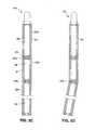
- FIG. 3Ais a plan view showing a first embodiment of an intravascular defibrillation and/or pacing device of a type which may be used with the system shown in FIG. 2 .
- FIG. 3Bis a plan view similar to FIG. 3A showing a second embodiment of an intravascular defibrillation and/or pacing device of a type which may be used with the system shown in FIG. 2 .
- FIG. 3Cis a plan view showing a third embodiment of an intravascular defibrillation and/or pacing device of a type which may be used with the system shown in FIG. 2 .
- FIG. 3Dis a plan view similar to FIG. 3C illustrating bending of the device.
- FIG. 4Ais a plan view showing a fourth embodiment of an intravascular defibrillation and/or pacing device of a type that may be used with the system shown in FIG. 2 .
- FIG. 4Bis a plan view showing the ribbon portion of the fourth embodiment.
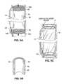
- FIG. 5Ais a perspective view schematically illustrating use of an anchor to anchor an intravascular defibrillation and/or pacing device within a vessel.
- FIG. 5Bis cross-sectional perspective view showing a portion of the anchor of FIG. 5A .
- FIG. 5Cis a perspective view similar to FIG. 5A but further illustrating use of a liner within the vessel.
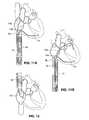
- FIG. 6Aschematically illustrates a first application of an intravascular defibrillation and/or pacing system.
- FIG. 6Bis a schematic illustration similar to FIG. 6A showing an alternative lead which includes a coiled section.
- FIG. 7schematically illustrates a second application of an intravascular defibrillation and/or pacing system.
- FIG. 8schematically illustrates a third application of an intravascular defibrillation and/or pacing system.
- FIG. 9Aschematically illustrates a fourth application of an intravascular defibrillation and/or pacing system.
- FIG. 9Bschematically illustrates a variation of the fourth application of FIG. 9A .
- FIG. 9Cschematically illustrates another variation of the fourth application of FIG. 9A .
- FIG. 10Aschematically illustrates a fifth application of an intravascular defibrillation and/or pacing system.
- FIG. 10Bschematically illustrates a variation of the fifth application of FIG. 10A .
- FIG. 11Aschematically illustrates a sixth application of an intravascular defibrillation and/or pacing system.
- FIG. 11Bschematically illustrates a variation on the sixth application of FIG. 11A
- FIG. 12schematically illustrates a seventh application of an intravascular defibrillation and/or pacing system.
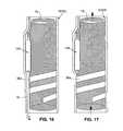
- FIGS. 13A through 17are a sequence of drawings illustrating deployment of the intravascular defibrillation and/or pacing device of FIG. 4A .
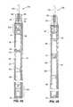
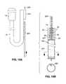
- FIG. 18Ais a plan view of a device similar to the devices of FIGS. 3A-4B but slightly modified to include a cuff on the lead for receiving a guidewire.
- FIG. 18Bis a plan view of a device similar to the devices of FIGS. 3A-4B but slightly modified to include a bore in the device for receiving a guidewire.
- FIG. 18Cis a plan view similar to FIG. 18B showing an alternative configuration for receiving a guidewire.
- FIG. 18Dis a plan view similar to FIG. 18A showing an alternative use of the FIG. 18A device and lead.
- FIG. 18Eis a cross-section view of the lead of FIG. 18D taken along the plane designated 18 E- 18 E in FIG. 18D .
- FIG. 1shows the cardiac anatomy of a human, including the heart and major vessels. The following anatomic locations are shown and identified by the listed reference numerals:
- RAARight Subclavian 2a Right Atrial Appendage
- CS OsCoronary Sinus Ostium
- SVCSuperior Vena Cava
- RVRight Ventricle
- IVCInferior Vena Cava
- LVLeft Ventricle
- LARight Atrium
- LALeft Atrium
- FIG. 2generally shows components that may be provided with an intravascular defibrillation and/or pacing system 10 .
- the elements of such a system 10may include defibrillation and/or pacing device 12 , one or more leads 14 a , 14 b , retention devices 16 , 16 a , and positioning mandrel 18 . It should be understood that certain of these elements may be eliminated, or others added to the system, without departing from the spirit of the invention.
- reference numerals such as 12 a , 12 b , 12 c etcwill be used to describe certain embodiments of the device, whereas elsewhere the numeral 12 may be used to more generally refer to devices of the type which may be used with the system 10 . Likewise, reference number 14 may be used generally to refer to leads of a type that may be used with the system.
- Device 12includes components known in the art to be necessary to carry out the system functions.
- device 12may include one or more pulse generators, including associated batteries, capacitors, microprocessors, and circuitry for generating defibrillation and/or pacing pulses.
- Devicealso includes detection circuitry for detecting arrhythmias or other abnormal activity of the heart. The specific components to be provided in the device will depend upon the application for the device, and specifically whether the device is intended to perform defibrillation, and/or pacing along with its sensing functions.
- the device 12is proportioned to be passed into the vasculature (for example into the venous system through the right or left femoral vein or the subclavian, or into the arterial system through one of the femoral arteries), and to be anchored within the patient's vasculature with minimal obstruction to blood flow.
- the housing of device 12preferably has a streamlined cross section which may be in the range of 3-10 mm or less, with a most preferred cross-section of 3-7 mm or less.
- the cross-section of the device(transecting the longitudinal axis) may have a circular cross-section, although other cross-sections including crescent, flattened, or elliptical cross-sections may also be used.
- FIGS. 3A , 3 B, 3 C, 4 A and 4 BExamples of devices having space efficient arrangements of their contents are shown in FIGS. 3A , 3 B, 3 C, 4 A and 4 B.
- One exampleis identified by reference numeral 12 a in FIG. 3A .
- Device 12 aincludes an elongate enclosure 20 shown in cross-section in FIG. 3A to allow the components housed within it to be seen.
- Enclosure 20is a rigid or semi-rigid housing preferably formed of a material that is conductive, biocompatible, capable of sterilization and capable of hermetically sealing the components contained within the enclosure 20 .
- a materialis titanium, although other materials may also be used.
- the housingis preferably covered by an electrically insulative layer or coating 21 such as ePTFE.
- an electrically insulative layer or coating 21such as ePTFE.
- a coating that is anti-thrombogenice.g. perfluorocarbon coatings applied using supercritical carbon dioxide
- the coatinghave anti-proliferative properties so as to minimize endothelialization or cellular ingrowth, since minimizing growth into or onto the device will help minimize vascular trauma when the device is explanted.
- the coatingmay thus also be one which elutes anti-thrombogenic compositions (e.g. heparin sulfate) and/or compositions that inhibit cellular ingrowth and/or immunosuppressive agents. As will be described below in connection with FIG. 6A , this layer or coating may be selectively applied or removed to leave an exposed electrode region 52 on the surface of the enclosure 20 .
- One or more leadsextend from device 12 a .
- a single lead 14 bis shown, although the device may include a defibrillation lead 14 b , a pacing lead 14 a , or both as shown in FIG. 2 .
- two leadsmay extend from opposite ends of the device as shown in FIG. 2 , or they may extend from the same end of the device.
- Either or both of the leadsmay be equipped to sense electrical activity of the heart. Monitoring of the heart's electrical activity is needed to detect the onset of an arrhythmia. Activity sensed by the sensing electrode(s) is used by the device electronics to trigger delivery of a defibrillation shock via lead 14 b or a pacing impulse via a pacing lead (such as lead 14 a of FIG. 2 ).
- the leads 14 a , 14 bmay be conventional defibrillation/pacing leads, although alternative lead configurations may be desirable if warranted by the desired placement of the device 12 a and leads within the body.
- the physicianwill preferably want to select a location for the device within a chosen vessel (i.e. the inferior or superior vena cava) that will prevent the device from blocking significant peripheral vessels extending from that vessel.
- Optimal leadswill preferably give the physician implanting the device flexibility to position the device at an appropriate location in the chosen vessel without concern that the leads extending from the device will not reach their intended location.
- the leadmay include a coiled section 100 ( FIG.
- Coiled section 100allows elongation of the effective length of the lead when tension is applied to the coil.
- Other configurations that will allow additional lead length to pay out from the device if neededmay also be used.
- the leadsmay be the screw-in or tined variety for fixation to the cardiac tissue, or they may have steroid-eluding tips to facilitate tissue in-growth for fixation purposes.
- the leadsmay include non-thrombogenic and/or non-proliferative surfaces or coatings as also described above in connection with the device 12 .
- FIG. 3Aillustrates one means for detachably connecting a lead to the device 12 a .
- device 12 aincludes a header 22 having a socket 24 .
- a pin 26 at the proximal end of lead 14 bis inserted into socket 24 .
- a series of o-ring seals 28surround the pin 26 within the socket 24 to prevent body fluids from passing into the device 12 a .
- a set screw 30tightens against the pin 26 to secure the pin within the socket.
- components 34 a , 34 bthat govern operation of the device 12 a .
- components 34 aare associated with delivery of a defibrillation pulse via lead 14 b
- components 32 bare associated with the sensing function performed using sensing electrodes on the defibrillation lead or on a separate lead (not shown). Isolating components 34 a from components 34 b may be desirable if noise generated by the high voltage defibrillation circuitry 34 a during charging might interfere with performance of the sensing circuitry 34 b.
- Device 12 afurther includes one or more batteries 36 for supplying power to the device, and one or more capacitors 38 for storing an electrical charge and for delivering stored charge to the defibrillation lead(s) 14 b and/or exposed electrode 52 on the enclosure 20 .
- a circuit interconnect 40provides the electrical coupling between the electronic components 34 a , 34 b , lead 14 b , electrode 52 , batteries 36 and capacitors 38 . Contacts 41 couple these components to the interconnect 40 .
- the components of device 12 amay be arranged in series with one another to give the device 12 a a streamlined profile. Because the device 12 a is intended for implantation within the patient's vasculature, some flexibility may be desired so as to allow the elongate device to be easily passed through the vasculature. Flexibility may be added by segmenting the device, such as by forming one or more breaks 23 in the enclosure 20 , and by forming one or more hinge zones 42 at each break 23 by connecting the segments using silicone rubber filler. The hinge zones 42 thus form living hinges, which bend in response to passage of the device 12 a though curved regions of the vasculature. It should be noted that in this embodiment it is desirable to form interconnect 40 as a flex circuit so that it will not prevent bending at the hinge zones.
- a proximal portion of the device 12 amay include a connector 44 for receiving the distal end of positioning mandrel 18 ( FIG. 2 ), which may optionally be used to push the device 12 a through the patient's vasculature as described below.
- the connector 44may take the form of a threaded bore for receiving a threaded screw member at the distal end of the mandrel 18 , or it may have any other type of configuration for detachably engaging the distal end of the mandrel.
- a second example of an arrangement of components for the intravascular defibrillation and/or pacing deviceis identified by reference numeral 12 b and shown in FIG. 3B . Many of the components are the same as those shown in the FIG. 3A embodiment and will not be discussed again in connection with FIG. 3B .
- This second embodimentdiffers from the first embodiment primarily in that the electronic components 34 are included within a single area of the enclosure 20 .
- This configurationmay be used, for example, when the device is intended only for performing pacing functions (and thus lacks the relatively noisy charging circuitry found in the defibrillation circuitry), or if isolation of the type shown in the FIG. 3A embodiment is not necessary to prevent noise from the charging circuit from interfering with the sensing circuits.
- FIGS. 3A and 3B embodimentsare the device 12 c shown in FIGS. 3C and 3D .
- each segmentmay be separately enclosed by its own titanium (or similar) enclosure 20 a , 20 b , 20 c .
- the components within the enclosures 20 a , 20 b , 20 care electrically connected by flex circuits 40 a , and the enclosures are connected using a flexible material such as silicone rubber filler to form hinge zones 42 a .
- FIG. 3Dillustrates bending of the device 12 c at one of the hinge zones.
- FIG. 4AA fourth embodiment of an intravascular defibrillation and/or pacing device is identified by reference numeral 12 d and shown in FIG. 4A . Many of the components are the same as those shown in the FIGS. 3A and 3B embodiments and will not be discussed again.
- the FIG. 4A embodimentdiffers from the prior embodiments largely in the configuration of the capacitor 38 a , which takes the form of a coiled ribbon mechanically coupled to the proximal end of the device 12 d (or to a more distal location) and electrically coupled to the circuit interconnect 40 .
- the coiled ribbonmay take the form of a flex circuit of the type described in connection with FIG. 4B below, or it may be formed of layers of capacitor material overlaying one another to form the ribbon itself.
- the capacitor 38 aPrior to implantation, the capacitor 38 a is compressible to a streamlined condition for introduction into the body. For example, it may be placed within a delivery sheath or it may retained in a streamlined position by winding the ribbon against the mandrel and retaining it with a shorter sleeve, suture or wire etc. As yet another example, proximal tension may be imparted on the ribbon by pulling the ribbon in the longitudinal direction, thereby elongating the ribbon while reducing its overall width, much like pulling on a coiled telephone wire. Once positioned within the vessel at the appropriate site for implantation, the capacitor is released from the compressed position and springs to an expanded position within the vessel, as further discussed in the section entitled “System Implantation” below.
- the ribbonis described as being a capacitor, it should be appreciated that a different subset of the device components may be provided in the form of a ribbon-like structure or circuit.
- the capacitormay be similar to the capacitors 38 shown in FIGS. 3A and 3B , and the device's battery may instead be formed in the coiled ribbon configuration.
- the coiled ribbonmay instead be an antenna for transmitting signals alerting a physician to the occurrence of an arrhythmia, and both the capacitor and battery may take the forms shown in FIGS. 3A and 3B , or some alternate form.
- FIG. 4Bis an enlarged view of the ribbon 102 used for capacitor 38 a of FIG. 4A .
- the ribbon 102is a coiled flex circuit electrically connected to the rest of the device 12 d by tab 101 .
- Discrete capacitor segments 106are preferably arranged in a stepped pattern on the ribbon surface and may be applied using spray-on/lithographic techniques or other means. Segments 106 have terminals 105 that may be connected in parallel using parallel connections 104 , or in series using series connections 107 as needed.
- the segments 106may be on the exterior surface of the ribbon 102 , and/or there may be additional segments or related components 103 (including integrated circuit components, passive circuitry components, microprocessor components etc.) on the interior surface of the coil.
- the entire devicemay take the form of a coiled ribbon flex circuit, with the components being located on the exterior or interior surface of the ribbon and with the leads coupled to the ribbon.
- the device 12is preferably able to communicate via wireless telemetry to an instrument outside of the patient's body. This is commonly referred to as device interrogation and/or programming and allows the physician to monitor the state and performance of the device. It also allows the physician to reconfigure the device in the case of programmable settings.
- the circuitry used for device interrogation and/or programmingcan be included in all of the device embodiments, with the device telemetry antenna either encapsulated within the device enclosure or as part of the ribbon component set.
- the circuitrymay include a circuit that will respond in the presence of a magnetic field, which is a feature also known in the implantable device industry. Either of these communication means, or both, are intended to allow the device to communicate the device's status to the physician.
- the status informationmay include the state of the battery system, and whether or not a therapeutic energy delivery had occurred or not.
- the communicationmight also identify the parameters the device used, including a stored electrogram, to allow reconstruction of the delivery episode by the instrument.
- the telemetry featuremay also be used to program certain features governing function of the device, such as the threshold heart rate in beats per minute which, when detected by the device, will cause the device to provide appropriate energy therapy.
- the system 10further includes a mechanism for retaining device 12 in the patient's vasculature, such as in the superior vena cava 3 a , inferior vena cava 3 b , or the left or right subclavian 2 a , 2 b (see FIG. 1 ).
- a retention deviceis a tubular retention sleeve or anchor 16 as shown in greater detail in FIGS. 5A and 5B .
- the retention deviceis described as a separate component from the device 12 , but it will be appreciated that the anchor 16 or other retention device may be integral with the device 12 .
- the anchor 16may include features that give some structural stability to cause the anchor to radially support the device against a vessel wall.
- a mesh or other framework 46FIG. 5B
- shape memorye.g. nickel titanium alloy, nitinol or shape memory polymer
- stainless steel wiresmay be used.
- the anchor 16is preferably provided with a smooth polymeric barrier 48 that is both anti-proliferative and anti-thrombogenic and that thereby prevents endothelial growth and thrombus formation on the anchor.
- Examples of materials for the polymeric barrierinclude, but are not limited to ePTFE, or other fluoropolymers, silicone, non-woven nylon, or biomimetic materials.
- the polymeric barrier 48is preferably formed by layers of barrier material on the interior and exterior surfaces of the framework, although it will be appreciated that the framework 46 and barrier 48 may be combined in a variety of ways to prevent thrombus formation and endothelialization on the anchor walls.
- the anchor materialcould include surfaces for eluting non-coagulative, anti-platelet (e.g. IIBIIIA glycoprotein receptor blockers), anti-proliferative, and/or anti-inflammatory substances.
- the framework 46may extend through the entire length of the anchor, or it may be included in only a portion of the anchor, such as at the proximal and distal end regions as shown in FIG. 5A , leaving the intermediate region between them with no structural reinforcement. This arrangement may be preferable in that is allows the intermediate region to conform to the surface of the device 12 during use. As another alternative, the intermediate region may include some structural reinforcement in the intermediate region 49 between the more rigid proximal and distal framework regions 46 , but less than is provided in the proximal and distal regions 46 so as to allow some conformability to the device surface.
- the anchor 16is compressed to a streamlined positioned for passage through the vasculature.
- the anchor 16may be inserted into a positioning sheath to facilitate movement through the vasculature.
- the anchorwill be introduced after the device has been positioned at a desired location within the vessel, although if the anchor and device are integral components they will be implanted simultaneously.
- the anchoris advanced to a position adjacent the device, released from the sheath (if used) and expanded to a radially expanded position as shown in FIG. 5A .
- the anchormay self-expand and/or it may be expanded using an inflation tool such as a balloon passed into the anchor's central lumen and subsequently inflated.
- an inflation toolsuch as a balloon passed into the anchor's central lumen and subsequently inflated.
- the anchorWhen the anchor is expanded, its radial forces engage the device 12 and secure the device 12 against the vessel wall. As shown, the force of the anchor against the device may cause the vessel to bulge outwardly. Blood flowing through the vessel passes through the tubular interior of the anchor as indicated by arrows in FIG. 5A . Because the device 12 occupies the bulge in the vessel, the presence of the device causes minimal (if any) obstruction to blood flowing
- the rims 50 a , 50 b surrounding the anchor's proximal and distal openingsare preferably designed to make sealing contact against the surrounding vessel tissue (and against the lead 14 b ) as shown in FIG. 5A so as to direct all blood flow into the interior of the anchor.
- rims 50 a , 50 bmay be formed of a thicker and more pliable material such as silicone or polyurethane-siloxane, or the rims may be supplemented with compliant members that seal against the lead and surrounding tissue.
- a swellable hydrogelwhich expands when placed in contact with fluids including blood, may be included on the anchor's ends to optimize sealing.
- these barrierswill form a seal with the adjacent tissue, however it is sufficient that the barriers prevent a substantial amount of blood from passing between the exterior of the anchor and the device, without necessarily forming an impermeable seal.
- anchor 16 a( FIG. 2 ) similar to the anchor 16 may also be used to anchor leads within the vasculature.
- a tubular liner 17may be deployed within the vessel prior to implantation of the device 12 and anchor 16 .
- Liner 17may be similar in design to the sheath 16 , but is preferably longer than either the device 12 or anchor 16 so that the liner contacts the vessel wall but the device 12 and anchor 16 do not. If used with the FIG. 4A embodiment of the device 12 d which includes coiled ribbon 38 a , the liner 17 is preferably longer than the combined length of the enclosure 20 and coil 38 a . The liner 17 helps to reduce the risk of trauma to the vessel tissue during explantation of the device and/or anchor 16 .
- the liner 17is deployed in the desired anatomic location before the device is moved into place.
- the steps for deploying the liner 17may be similar to those described above for deploying the anchor 16 .
- the deviceis deployed, followed by the anchor 16 , in the same manner as described elsewhere.
- the linermay become endothelialized, particularly at its edges.
- the endothelial growthis self limiting to the edge or rim of the liner due to increasing distance from a sustaining blood supply and should not reach the inner retaining sleeve 16 .
- the inner anchor 16may be grabbed by a surgical instrument with the outer liner 17 acting as a protective layer for the vessel.
- the liner 17may be left in place following removal of the anchor 16 and device 12 . If the device 12 (or a replacement) is to be later re-implanted, it may be returned to its original location within the liner 17 .
- the device 12may be “sandwiched” between the liner 17 and anchor 16 before implantation by placing the device inside the liner, then placing the anchor in a compressed position within the liner, and then expanding the anchor to engage the device between the sleeve and anchor. The three components are then compressed into a positioning sheath and introduced as described elsewhere.
- System 10( FIG. 2 ) is adaptable for use in a variety of applications, including single chamber atrial or ventricular pacing, dual chamber (atrial and ventricular) pacing, bi-atrial pacing for the suppression of atrial fibrillation, bi-ventricular pacing for heart failure patients, ventricular defibrillation for ventricular tachycardia or ventricular fibrillation, and atrial defibrillation for patients suffering from atrial fibrillation.
- the systemmay be adapted to perform multiple functions for use in combinations of these applications.
- the systemmay be implanted for permanent use, or it may be implanted for temporary use until more permanent interventions can be used
- FIGS. 6A through 12illustrate some of these applications as well as some configurations of the system that are suitable for each application.
- the defibrillation and/or pacing device embodiments 12 a , 12 b , 12 c , and 12 d shown in FIGS. 3A-4B and the anchor 16 of FIG. 5Amay be used for the described applications, although numerous alternative forms of defibrillation and/or pacing devices and anchoring mechanisms may also be used without departing from the scope of the invention.
- each of the described applicationsinvolves placement of the device in the venous system, it should be noted that it may alternatively be placed within the arterial system (such as to allow generation of defibrillation vectors from the aortic arch to the descending aorta) if warranted.
- FIGS. 6A and 6Bshow components of the FIG. 2 system 10 as used as an implanted cardioverter defibrillator (ICD) for treatment of ventricular fibrillation.
- ICDimplanted cardioverter defibrillator
- device 12is anchored in the inferior vena cava 3 b using anchor 16 .
- a defibrillation lead 14 bis included with the system 10 and is anchored within the patient's left subclavian.
- An anchor 16 a similar to the anchor 16may be used for this purpose.
- Anchor 16 amay be smaller than anchor 16 since the lead 14 b it anchors is relatively lighter than the device anchored by anchor 16 , and because the anchor 16 d is positioned within the smaller-diameter left subclavian.
- the lead 14 bmay include a coiled section 100 as shown in FIG. 6B to permit elongation of the effective length of the lead in response to longitudinal tension.
- Lead 14 bincludes a high voltage electrode surface 54 through which the defibrillation pulse is delivered.
- the defibrillation shock vectorflows between electrode surface 54 on the lead and the electrode surface 52 on the device 12 as indicated by arrows.
- Orienting the electrode 52 towards the heart as shown in FIG. 6Acontributes to focusing of the defibrillation current.
- the anchor 16functions as an insulator, it helps to minimize conduction of the high voltage current away from the heart and thus also facilitates current focusing. Configuring the system to focus the current can reduce the amount of defibrillation energy needed to defibrillate the patient, since less energy is lost to surrounding tissue, and allows a smaller capacitor to be used within the system. This is beneficial in that in reduces the overall size of the device 12 and further ensures that the device profile will not interfere with blood flow within the vessel.
- electrode surface 52is shown positioned towards one side of the device, it may take other forms.
- the electrode surfacemay instead extend around the device body to form a band. Focusing is facilitated in this embodiment by positioning the anchor 16 against the side of the device that is furthest from the heart (as is also done in the FIG. 6A application), so as to thereby minimize conduction of the high voltage current from the electrode 52 away from the heart.
- electrical activity of the heartmay be sensed between the high voltage electrode 54 on the lead 14 b and the electrode 52 on device 12 .
- Device 12may alternatively include one or more sensing electrodes (not shown) on its surface for detecting electrical activity of the heart.
- FIG. 7illustrates a second application for the FIG. 2 system 10 .
- This applicationis similar to the first application in that it uses the device 12 as an implantable cardioverter defibrillator (“ICD”), but it further includes a pacing lead 14 a positioned in the right ventricle.
- Pacing lead 14 amay be a conventional lead, which includes one or more sensing and pacing electrodes 56 .
- a bi-polar lead of a type commonly used for ICD's and pacemakersmay be used, in which case sensing could be carried out between two spaced-apart electrodes on the lead.
- a smaller leadit may be provided with a single sensing electrode and sensing could be accomplished between the single electrode and an exposed electrode (see electrode 52 , FIG. 6 ) on device 12 .
- FIG. 7shows the defibrillation lead 14 b and the sensing lead 14 a extending from opposite ends of the device 12 , both leads may instead extend from one end of the device.
- the FIG. 7 arrangementmay be configured such that the shock vector applied to the heart extends from the defibrillation electrode 54 and a location on the device 12 as indicated by arrows.
- a high voltage leadmay be used as the lead 14 a , in which case the device could be configured to apply the shock vector between electrode 54 and the electrode 56 on lead 14 a.
- a third applicationis shown in FIG. 8 .
- the third applicationis largely similar to the second application, but uses a device 12 d that is divided into two separate housings 58 a , 58 b .
- housing 58 amay contain the components needed for defibrillation (e.g. the electronics, capacitors and the batteries) while housing 58 b contains the components associated with the sensing function (e.g. the electronics and associated batteries).
- Dividing components into separate packagesmay provide several advantages. First, it allows for use of an anchor having a shorter longitudinal dimension, which facilitates placement of the anchor in a location where it will not obstruct blood flow into/from peripheral vasculature.
- the separate packagescan be anchored by a single anchor as shown in FIG. 8 , or the packages may be positioned in series in the vessel and separate anchors may be used for each.
- battery lifemay be optimized by using separate batteries for pacing and defibrillation—thereby supporting each function with a battery type most suitable for the function and optimizing battery life.
- one or more batteries having chemistries of the type used for pacemaker batteriestypically lithium iodide batteries which can come in very small sizes due to their high energy density
- Batteries having chemistries similar to typical implantable defibrillator batteries, which are faster charging and which can produce larger current surges than pacing batteries, (e.g. LSOV)may be separately used for the defibrillation function.
- An inter-device cable 60provides communication between the components of the housings 58 a , 58 b , although other forms of communication (e.g. wireless RF, infrared, acoustic, telemetric) might also be used.
- the structural framework 46 of anchor 16FIG. 5B
- FIG. 9Ashows an alternative application in which the FIG. 2 system 10 is used for single-chamber ventricular pacing.
- device 12is anchored by anchor 16 in the superior vena cava 3 a .
- the distal end of pacing lead 14 ais positioned in the right ventricle 7 a .
- the device 12 and anchor 16may alternatively be positioned within the inferior vena cava 3 b .
- a leadless device 12 e having a surface pacing electrode 64is itself positioned within the right ventricle 7 a.
- FIG. 10Ashows an alternative application in which the FIG. 2 system 10 is used as an implanted cardioverter for atrial fibrillation, with device 12 anchored by anchor 16 in the superior vena cava 3 a , and a sensing/pacing lead 14 a having electrode 56 extending through the coronary sinus.
- the shock vectorextends between an exposed electrode on device 12 and electrode 56 within the coronary sinus.
- FIG. 10Bshows an alternative to the FIG. 10A configuration for atrial fibrillation, in which the device 12 may be positioned in the inferior vena cava 3 b and a high voltage electrode lead 66 placed in the superior vena cava 3 a and supported by another anchoring device such as anchor 16 c .
- the cardioversion shock vectorextends between a distal electrode on pacing lead 14 a and a high voltage electrode 67 on lead 66 .
- FIGS. 11A and 11Bshows use of the FIG. 2 system 10 as a dual chamber pacer having two pacing leads 14 a .
- Device 12is anchored in the inferior vena cava 3 b using anchor 16 .
- the FIG. 11A embodimentis shown positioned for pacing the right and left ventricles. Ventricular pacing is performed by one of the pacing leads 14 a which is positioned in the right ventricle 7 a as shown, and atrial pacing is performed using another pacing lead 14 a that is positioned in contact with the intra-atrial septum.
- the FIG. 11B embodimentis shown positioned for bi-ventricular pacing, with each of the pacing leads 14 a positioned in one of the ventricles.
- FIG. 12shows use of the FIG. 2 system 10 for atrial pacing.
- an atrial J-lead 14 cis coupled to the device 12 and is positioned in contact with the intra-atrial septum.
- the system 10may be implanted using a variety of techniques. Six examples of these techniques will next be described. Although most of the examples describe implantation through the femoral vein, it should be understood that alternate approaches (e.g. through the subclavian, or through both femoral veins) without departing from the scope of the invention.
- the first implantation methodwill be described with respect to the device 12 d of FIGS. 13A and 13B , but is appropriate for implantation of the other devices described herein, as well.
- a small incisionis formed in the femoral vein and an introducer sheath is inserted through the incision into the vein to keep the incision open during the procedure.
- positioning mandrel 18is attached to the proximal end of the device 12 d .
- Device 12 dis advanced into the introducer sheath, and pushed using mandrel 18 (preferably under fluoroscopic visualization) to the desired location.
- a portion of the devicemay be enclosed within a sleeve 68 , particularly for embodiments having expandable components such as ribbon coil 38 a which must be compressed to a streamlined position for passage through the vessel.
- FIG. 13A and 13Ba portion of the device may be enclosed within a sleeve 68 , particularly for embodiments having expandable components such as ribbon coil 38 a which must be compressed to a streamlined position for passage through the vessel.
- the ribbon coil 38 ais released from the sleeve 68 once the device 12 has been advanced by mandrel 18 to the desired position, and the ribbon coil 38 a springs to its expanded condition in contact with the vessel walls once the device 12 d is released from the distal end of the catheter.
- the expanded coilmay take the form shown in FIG. 13B , or it may spiral into overlapping layers to shorten its longitudinal dimension. A balloon may be expanded within the coil if needed for full expansion.
- FIGS. 14-17illustrate one method for anchoring the device using anchor 16 . Although these figures illustrate anchoring of device 12 d , they are equally applicable to deployment of other devices within the vasculature, including the devices 12 , 12 a , and 12 b and 12 c.
- FIG. 14shows the device 12 d of FIG. 4A (attached to mandrel 18 ) after it has been advanced into the vessel and after the ribbon coil 38 a has been released to the expanded position.
- a sheath 62 with the anchor 16 inside itis positioned in parallel with the device 12 d while the device 12 d is held in place using the mandrel 18 .
- the sheath 62is withdrawn as shown, releasing anchor 16 into the vessel.
- the sheath 62facilitates placement of the anchor, it should be considered optional.
- the anchorself-expands or is expanded using an expansion device such as balloon (not shown) inflated within the anchor's central lumen, causing the anchor to radially engage the device 12 d against the vessel wall. See FIG. 16 .
- an expansion devicesuch as balloon (not shown) inflated within the anchor's central lumen, causing the anchor to radially engage the device 12 d against the vessel wall. See FIG. 16 .
- the deviceis anchored at the target location.
- the leadextends from the device and is located outside the body.
- a steerable guidewire 200is threaded through the lead 14 near the lead's free end as shown in FIG. 18A and is passed through the introducer sheath into the vein and steered to the desired location.
- the leadpreferably includes a cuff 203 for receiving the guidewire for this purpose.
- a pusher 204is then threaded over the guidewire and advanced into contact with the cuff 204 . Because cuff 203 is attached to the lead 14 , advancing pusher 204 pushes the lead 14 to the target site.
- the leadis held in place while a sheath (similar to sheath 62 of FIG. 14 ) having anchor 16 a ( FIG. 6A ) positioned inside it is moved into position in parallel with a distal portion of the lead.
- the sheathis withdrawn, releasing anchor 16 a into the vessel.
- the anchorself-expands or is expanded using an expansion device such as balloon (not shown) inflated within the anchor's central lumen, causing the anchor to radially compress the lead against the vessel wall.
- the target lead locationmay be secured at the target site using conventional securing means such as a helical fixation tip or tines on the distal end of the lead.
- implantation of the systeminvolves first positioning the lead(s) at the desired location (i.e. in a vessel or in a chamber of the heart) and then positioning the device at the appropriate position.
- lead implantationpreferably uses over-the-wire techniques that are widely used for cardiac lead placement.
- an introducer sheathis inserted into the femoral vein (or elsewhere in the vasculature) and a steerable guidewire is inserted into the introducer sheath.
- the physicianguides the wire to the intended lead location. For example, for positioning according to the embodiment of FIG. 6A , the guidewire would be directed to the patient's left subclavian vein 2 b , whereas for positioning according to the embodiment of FIG. 9B , the guidewire would be directed to the right ventricle 7 a.
- the leade.g. lead 14 b of FIG. 6A or lead 14 a of FIG. 9B
- the leadis threaded over the wire and pushed by the physician to the desired location.
- the leadis anchored at the desired location as described in connection with the first exemplary method. If a second lead is to be implanted, the process is repeated for the second lead.
- Implantation of the device 12begins once the distal end of the lead has been anchored at the target location. At this point the proximal end of the lead preferably extends outside the body from the introducer sheath, which remains in the open vein. If the lead is provided as a separate component from the device, the lead is next attached to the device 12 .
- positioning mandrel 18( FIG. 2 ) is attached to the proximal end of the device 12 .
- Device 12is advanced into the introducer sheath, and pushed using mandrel 18 (preferably under fluoroscopic visualization) to the desired location.
- mandrel 18preferably under fluoroscopic visualization
- the positioning sheath, mandrel, and introducer sleeveare withdrawn from the patient.
- the third example of an implantation methodis similar to the second example, but differs in that the leads and device are simultaneously advanced using the over-the-wire technique. As such, the third example is particularly useful for devices having pre-attached leads.
- the lead and/or deviceis modified to allow the lead to be advanced over a guidewire even though it is attached to the device.
- the body of the device 12 fmay be provided with a bore 202 that receives the same guidewire that also extends through the lead 14 .
- a channel 204may extend through a portion of the device 12 g as shown in FIG. 18C .
- the guidewire 200extends through the lead, into the channel 204 , and then runs along the exterior of the device 12 g .
- the lead 14is modified to include a cuff 203 that receives the guidewire 200 externally of the lead, allowing the guidewire to run alongside the device 12 .
- FIGS. 18A and 18Bshow o-ring seals 28 and a set screw 201 , these features may be eliminated if the lead and device are provided to be integral with one another.
- an introducer sheathis inserted into the femoral vein and a steerable guidewire 200 is inserted into the introducer sheath.
- the physicianguides the guidewire to the intended lead location as described above.
- the lead 14is threaded over the guidewire. If the FIG. 18B configuration is used, the proximal end of the guidewire 200 is threaded through the lead 14 and then passes through the bore in device 12 f . If the FIG. 18C configuration is used, the proximal end of the guidewire passes from the lead into channel 204 in the device header, and then exits the device 12 g . In either case, the lead is passed into the introducer sheath.
- the mandrel 18(see FIGS. 2 and 13 A- 16 ) is preferably attached to the device body and used to push the device and lead over the guidewire through the vasculature. Once the lead has reached the desired location, it is anchored at the desired location as described in connection with the first exemplary method. The mandrel 18 is used to maneuver the device to the target device position, and the device is anchored in place using the anchor as described above.
- the distal portion of the guidewireis threaded through cuff 203 , and the mandrel 18 (FIGS. 2 and 13 A- 16 ) is attached to the device.
- the leadis passed into the introducer sheath.
- a pusher 204is likewise threaded over the guide wire and advanced into contact with cuff 203 .
- the pusher 204is further advanced to push the lead to the desired location, at which time the lead is anchored as described.
- the mandrel 18is used to advance the device to the appropriate device position, and the device is then anchored in place.
- a fourth example of an implantation methodutilizes steps from both the first and third examples and is useful for device configurations such as the FIG. 7 configuration in which leads 14 a , 14 b extend from opposite ends of the device.
- the lead 14 b and device 12are first implanted using the procedure of the third example, thus leaving the lead 14 a extending out the incision in the femoral vein. Lead 14 a is then carried into the vein and pushed to the desired position using the procedure of the first example.
- incisionsare formed in the patient's subclavian 2 b and in the femoral vein and introducer sheaths are inserted into each vessel.
- a guidewireis passed into the introducer sheath in the subclavian, through the right atrium to the superior vena cava and through the introducer sheath in the femoral vein.
- the guidewireis attached to the lead in a manner similar to that described with the first example, and is then withdrawn at the subclavian incision, thereby pulling the lead into the subclavian and drawing the device 12 into the inferior vena cava.
- the mandrel 18may be used as described above to facilitate “fine-tuning” of the device position.
- the lead and deviceare anchored as described above.
- the “leadless” embodiment of FIG. 9Cmay be provided with a bore or similar means for receiving a guidewire, in which case it may be implanted by first directing a guidewire through the subclavian or inferior vena cava to the right ventricle, threading the device over the guide wire, and then pushing the device (e.g. using mandrel 18 ) to the ventricle.
- the devicemay be advanced through a hollow catheter having its distal end positioned in the right ventricle.
Landscapes
- Health & Medical Sciences (AREA)
- Cardiology (AREA)
- Heart & Thoracic Surgery (AREA)
- Engineering & Computer Science (AREA)
- Biomedical Technology (AREA)
- Nuclear Medicine, Radiotherapy & Molecular Imaging (AREA)
- Radiology & Medical Imaging (AREA)
- Life Sciences & Earth Sciences (AREA)
- Animal Behavior & Ethology (AREA)
- General Health & Medical Sciences (AREA)
- Public Health (AREA)
- Veterinary Medicine (AREA)
- Electrotherapy Devices (AREA)
Abstract
Description
| Right Subclavian | 2a | Right Atrial Appendage (RAA) | 5 | |
| Left | 2b | Coronary Sinus Ostium (CS Os) | 6 | |
| Superior Vena Cava (SVC) | 3a | Right Ventricle (RV) | 7a | |
| Inferior Vena Cava (IVC) | 3b | Left Ventricle (LV) | 7b | |
| Right Atrium (RA) | Aortic Arch | 8 | ||
| Left Atrium (LA) | Descending Aorta | 9 | ||
Claims (30)
Priority Applications (7)
| Application Number | Priority Date | Filing Date | Title |
|---|---|---|---|
| US10/453,971US8239045B2 (en) | 2003-06-04 | 2003-06-04 | Device and method for retaining a medical device within a vessel |
| US10/977,060US7617007B2 (en) | 2003-06-04 | 2004-10-29 | Method and apparatus for retaining medical implants within body vessels |
| US11/443,841US7734343B2 (en) | 2003-06-04 | 2006-05-31 | Implantable intravascular device for defibrillation and/or pacing |
| US11/702,000US8116883B2 (en) | 2003-06-04 | 2007-02-02 | Intravascular device for neuromodulation |
| US12/506,232US7840282B2 (en) | 2003-06-04 | 2009-07-20 | Method and apparatus for retaining medical implants within body vessels |
| US12/908,086US8886340B2 (en) | 2003-06-04 | 2010-10-20 | Method and apparatus for retaining medical implants within body vessels |
| US14/262,673US9545512B2 (en) | 2003-06-04 | 2014-04-25 | Method and apparatus for retaining medical implants within body vessels |
Applications Claiming Priority (1)
| Application Number | Priority Date | Filing Date | Title |
|---|---|---|---|
| US10/453,971US8239045B2 (en) | 2003-06-04 | 2003-06-04 | Device and method for retaining a medical device within a vessel |
Related Parent Applications (1)
| Application Number | Title | Priority Date | Filing Date |
|---|---|---|---|
| US10/862,113Continuation-In-PartUS7529589B2 (en) | 2003-06-04 | 2004-06-04 | Intravascular electrophysiological system and methods |
Related Child Applications (5)
| Application Number | Title | Priority Date | Filing Date |
|---|---|---|---|
| US10/454,223Continuation-In-PartUS7082336B2 (en) | 2003-06-04 | 2003-06-04 | Implantable intravascular device for defibrillation and/or pacing |
| US10/454,223ContinuationUS7082336B2 (en) | 2003-06-04 | 2003-06-04 | Implantable intravascular device for defibrillation and/or pacing |
| US10/977,060Continuation-In-PartUS7617007B2 (en) | 2003-06-04 | 2004-10-29 | Method and apparatus for retaining medical implants within body vessels |
| US11/443,841ContinuationUS7734343B2 (en) | 2003-06-04 | 2006-05-31 | Implantable intravascular device for defibrillation and/or pacing |
| US11/702,000Continuation-In-PartUS8116883B2 (en) | 2003-06-04 | 2007-02-02 | Intravascular device for neuromodulation |
Publications (2)
| Publication Number | Publication Date |
|---|---|
| US20040249431A1 US20040249431A1 (en) | 2004-12-09 |
| US8239045B2true US8239045B2 (en) | 2012-08-07 |
Family
ID=33489630
Family Applications (1)
| Application Number | Title | Priority Date | Filing Date |
|---|---|---|---|
| US10/453,971Expired - Fee RelatedUS8239045B2 (en) | 2003-06-04 | 2003-06-04 | Device and method for retaining a medical device within a vessel |
Country Status (1)
| Country | Link |
|---|---|
| US (1) | US8239045B2 (en) |
Cited By (32)
| Publication number | Priority date | Publication date | Assignee | Title |
|---|---|---|---|---|
| US20120059431A1 (en)* | 2006-02-03 | 2012-03-08 | Williams Michael S | Intravascular Device for Neuromodulation |
| US20120090627A1 (en)* | 2010-04-14 | 2012-04-19 | Terrence Ransbury | Dislodgement detector for intravascular implantable medical device |
| US9289612B1 (en) | 2014-12-11 | 2016-03-22 | Medtronic Inc. | Coordination of ventricular pacing in a leadless pacing system |
| US9399140B2 (en) | 2014-07-25 | 2016-07-26 | Medtronic, Inc. | Atrial contraction detection by a ventricular leadless pacing device for atrio-synchronous ventricular pacing |
| US9492669B2 (en) | 2014-11-11 | 2016-11-15 | Medtronic, Inc. | Mode switching by a ventricular leadless pacing device |
| US9492668B2 (en) | 2014-11-11 | 2016-11-15 | Medtronic, Inc. | Mode switching by a ventricular leadless pacing device |
| US9623234B2 (en) | 2014-11-11 | 2017-04-18 | Medtronic, Inc. | Leadless pacing device implantation |
| US9724519B2 (en) | 2014-11-11 | 2017-08-08 | Medtronic, Inc. | Ventricular leadless pacing device mode switching |
| US9878150B2 (en) | 2005-09-12 | 2018-01-30 | The Cleveland Clinic Foundation | Methods and systems for increasing heart contractility by neuromodulation |
| US10172549B2 (en) | 2016-03-09 | 2019-01-08 | CARDIONOMIC, Inc. | Methods of facilitating positioning of electrodes |
| US20190126051A1 (en)* | 2016-05-03 | 2019-05-02 | Newpace Ltd. | Flexible semi-hermetic implantable medical device structure |
| US10390720B2 (en) | 2014-07-17 | 2019-08-27 | Medtronic, Inc. | Leadless pacing system including sensing extension |
| US10398901B2 (en) | 2015-02-06 | 2019-09-03 | Cardiac Pacemakers, Inc. | Systems and methods for treating cardiac arrhythmias |
| US10493278B2 (en) | 2015-01-05 | 2019-12-03 | CARDIONOMIC, Inc. | Cardiac modulation facilitation methods and systems |
| US10576273B2 (en) | 2014-05-22 | 2020-03-03 | CARDIONOMIC, Inc. | Catheter and catheter system for electrical neuromodulation |
| US10716944B2 (en) | 2017-03-20 | 2020-07-21 | Cardiac Pacemakers, Inc. | Systems and methods for treating cardiac arrhythmias |
| US10722716B2 (en) | 2014-09-08 | 2020-07-28 | Cardionomia Inc. | Methods for electrical neuromodulation of the heart |
| US10894160B2 (en) | 2014-09-08 | 2021-01-19 | CARDIONOMIC, Inc. | Catheter and electrode systems for electrical neuromodulation |
| US10894167B2 (en) | 2017-12-22 | 2021-01-19 | Cardiac Pacemakers, Inc. | Implantable medical device for vascular deployment |
| US10994148B2 (en) | 2017-03-20 | 2021-05-04 | Cardiac Pacemakers, Inc. | Systems and methods for treating cardiac arrhythmias |
| US11000690B2 (en) | 2017-03-20 | 2021-05-11 | Cardiac Pacemakers, Inc. | Systems and methods for treating cardiac arrhythmias |
| US11077298B2 (en) | 2018-08-13 | 2021-08-03 | CARDIONOMIC, Inc. | Partially woven expandable members |
| US11123570B2 (en) | 2017-12-22 | 2021-09-21 | Cardiac Pacemakers, Inc. | Implantable medical device for vascular deployment |
| US11160989B2 (en) | 2017-03-20 | 2021-11-02 | Cardiac Pacemakers, Inc. | Systems and methods for treating cardiac arrhythmias |
| US11207527B2 (en) | 2016-07-06 | 2021-12-28 | Cardiac Pacemakers, Inc. | Method and system for determining an atrial contraction timing fiducial in a leadless cardiac pacemaker system |
| US11446510B2 (en) | 2019-03-29 | 2022-09-20 | Cardiac Pacemakers, Inc. | Systems and methods for treating cardiac arrhythmias |
| US11510697B2 (en) | 2019-09-11 | 2022-11-29 | Cardiac Pacemakers, Inc. | Tools and systems for implanting and/or retrieving a leadless cardiac pacing device with helix fixation |
| US11559687B2 (en) | 2017-09-13 | 2023-01-24 | CARDIONOMIC, Inc. | Methods for detecting catheter movement |
| US11571582B2 (en) | 2019-09-11 | 2023-02-07 | Cardiac Pacemakers, Inc. | Tools and systems for implanting and/or retrieving a leadless cardiac pacing device with helix fixation |
| US11607176B2 (en) | 2019-05-06 | 2023-03-21 | CARDIONOMIC, Inc. | Systems and methods for denoising physiological signals during electrical neuromodulation |
| US11612749B2 (en) | 2016-04-01 | 2023-03-28 | Livanova Usa, Inc. | Vagus nerve stimulation patient selection |
| US11833349B2 (en) | 2019-03-29 | 2023-12-05 | Cardiac Pacemakers, Inc. | Systems and methods for treating cardiac arrhythmias |
Families Citing this family (121)
| Publication number | Priority date | Publication date | Assignee | Title |
|---|---|---|---|---|
| US7082336B2 (en)* | 2003-06-04 | 2006-07-25 | Synecor, Llc | Implantable intravascular device for defibrillation and/or pacing |
| US8239045B2 (en) | 2003-06-04 | 2012-08-07 | Synecor Llc | Device and method for retaining a medical device within a vessel |
| CA2527909A1 (en)* | 2003-06-04 | 2005-01-06 | Synecor Llc | Intravascular electrophysiological system and methods |
| US7617007B2 (en) | 2003-06-04 | 2009-11-10 | Synecor Llc | Method and apparatus for retaining medical implants within body vessels |
| EP1701766A2 (en) | 2003-12-12 | 2006-09-20 | Synecor, LLC | Implantable medical device having pre-implant exoskeleton |
| US7363082B2 (en)* | 2005-03-24 | 2008-04-22 | Synecor Llc | Flexible hermetic enclosure for implantable medical devices |
| US7684864B2 (en)* | 2005-04-28 | 2010-03-23 | Medtronic, Inc. | Subcutaneous cardioverter-defibrillator |
| US7627376B2 (en)* | 2006-01-30 | 2009-12-01 | Medtronic, Inc. | Intravascular medical device |
| WO2007117538A2 (en)* | 2006-04-03 | 2007-10-18 | Innerpulse, Inc. | Flexible interconnect assembly for implantable medical devices |
| WO2007146060A2 (en)* | 2006-06-07 | 2007-12-21 | Cherik Bulkes | Self-anchoring electrical lead with multiple electrodes |
| US20070288077A1 (en)* | 2006-06-07 | 2007-12-13 | Cherik Bulkes | Self-anchoring electrical lead with multiple electrodes |
| US7865249B2 (en)* | 2006-09-22 | 2011-01-04 | Cardiac Pacemakers, Inc. | Means to securely fixate pacing leads and/or sensors in vessels |
| US7894915B1 (en) | 2006-10-27 | 2011-02-22 | Pacesetter, Inc. | Implantable medical device |
| US7899537B1 (en) | 2006-10-27 | 2011-03-01 | Pacesetter, Inc. | Pericardial cardioverter defibrillator |
| US8311633B2 (en)* | 2006-12-04 | 2012-11-13 | Synecor Llc | Intravascular implantable device having superior anchoring arrangement |
| US20080147168A1 (en)* | 2006-12-04 | 2008-06-19 | Terrance Ransbury | Intravascular implantable device having detachable tether arrangement |
| US20090082838A1 (en)* | 2007-09-26 | 2009-03-26 | Cardiac Pacemakers, Inc. | Left-ventricular lead fixation device in coronary veins |
| US8204596B2 (en)* | 2007-10-31 | 2012-06-19 | Synecor Llc | Isolation connector for an intravascular implantable medical device |
| WO2009073754A2 (en) | 2007-12-03 | 2009-06-11 | Innerpulse | Implantation methods, systems and tools for intravascular implantable devices |
| US7925352B2 (en) | 2008-03-27 | 2011-04-12 | Synecor Llc | System and method for transvascularly stimulating contents of the carotid sheath |
| WO2009137530A2 (en) | 2008-05-05 | 2009-11-12 | Coherex Medical, Inc. | Ventricular assist device and related methods |
| US8540616B2 (en) | 2008-05-05 | 2013-09-24 | Coherex Medical, Inc. | Ventricular assist device and related methods |
| US8239037B2 (en)* | 2008-07-06 | 2012-08-07 | Synecor Llc | Intravascular implant anchors having remote communication and/or battery recharging capabilities |
| US8412349B2 (en)* | 2009-06-04 | 2013-04-02 | Boston Scientific Neuromodulation Corporation | Three-piece button anchor and methods and devices using the anchor |
| US20110004288A1 (en)* | 2009-06-12 | 2011-01-06 | Terrance Ransbury | Intravascular implantable device having integrated anchor mechanism |
| US20100318166A1 (en)* | 2009-06-12 | 2010-12-16 | Terrance Ransbury | Methods and systems for anti-thrombotic intravascular implantable devices |
| US8433409B2 (en)* | 2010-01-29 | 2013-04-30 | Medtronic, Inc. | Implantable medical device battery |
| US8532790B2 (en)* | 2010-04-13 | 2013-09-10 | Medtronic, Inc. | Slidable fixation device for securing a medical implant |
| US8478431B2 (en)* | 2010-04-13 | 2013-07-02 | Medtronic, Inc. | Slidable fixation device for securing a medical implant |
| US9457186B2 (en) | 2010-11-15 | 2016-10-04 | Bluewind Medical Ltd. | Bilateral feedback |
| WO2013111137A2 (en) | 2012-01-26 | 2013-08-01 | Rainbow Medical Ltd. | Wireless neurqstimulatqrs |
| WO2014087337A1 (en) | 2012-12-06 | 2014-06-12 | Bluewind Medical Ltd. | Delivery of implantable neurostimulators |
| WO2015106015A1 (en) | 2014-01-10 | 2015-07-16 | Cardiac Pacemakers, Inc. | Systems and methods for detecting cardiac arrhythmias |
| AU2015204693B2 (en) | 2014-01-10 | 2017-03-23 | Cardiac Pacemakers, Inc. | Methods and systems for improved communication between medical devices |
| CN107073275B (en) | 2014-08-28 | 2020-09-01 | 心脏起搏器股份公司 | Medical device with triggered blanking period |
| US9764146B2 (en) | 2015-01-21 | 2017-09-19 | Bluewind Medical Ltd. | Extracorporeal implant controllers |
| US9597521B2 (en) | 2015-01-21 | 2017-03-21 | Bluewind Medical Ltd. | Transmitting coils for neurostimulation |
| US10004896B2 (en) | 2015-01-21 | 2018-06-26 | Bluewind Medical Ltd. | Anchors and implant devices |
| EP3253449B1 (en) | 2015-02-06 | 2018-12-12 | Cardiac Pacemakers, Inc. | Systems for safe delivery of electrical stimulation therapy |
| AU2016215606B2 (en) | 2015-02-06 | 2018-05-31 | Cardiac Pacemakers, Inc. | Systems and methods for treating cardiac arrhythmias |
| US10046167B2 (en) | 2015-02-09 | 2018-08-14 | Cardiac Pacemakers, Inc. | Implantable medical device with radiopaque ID tag |
| CN107530002B (en) | 2015-03-04 | 2021-04-30 | 心脏起搏器股份公司 | System and method for treating cardiac arrhythmias |
| US10050700B2 (en) | 2015-03-18 | 2018-08-14 | Cardiac Pacemakers, Inc. | Communications in a medical device system with temporal optimization |
| EP3270768B1 (en) | 2015-03-18 | 2023-12-13 | Cardiac Pacemakers, Inc. | Communications in a medical device system with link quality assessment |
| US9782589B2 (en) | 2015-06-10 | 2017-10-10 | Bluewind Medical Ltd. | Implantable electrostimulator for improving blood flow |
| CN108136186B (en) | 2015-08-20 | 2021-09-17 | 心脏起搏器股份公司 | System and method for communication between medical devices |
| CN108136187B (en) | 2015-08-20 | 2021-06-29 | 心脏起搏器股份公司 | System and method for communication between medical devices |
| US9968787B2 (en) | 2015-08-27 | 2018-05-15 | Cardiac Pacemakers, Inc. | Spatial configuration of a motion sensor in an implantable medical device |
| US9956414B2 (en) | 2015-08-27 | 2018-05-01 | Cardiac Pacemakers, Inc. | Temporal configuration of a motion sensor in an implantable medical device |
| WO2017040115A1 (en) | 2015-08-28 | 2017-03-09 | Cardiac Pacemakers, Inc. | System for detecting tamponade |
| US10137305B2 (en) | 2015-08-28 | 2018-11-27 | Cardiac Pacemakers, Inc. | Systems and methods for behaviorally responsive signal detection and therapy delivery |
| US10226631B2 (en) | 2015-08-28 | 2019-03-12 | Cardiac Pacemakers, Inc. | Systems and methods for infarct detection |
| WO2017044389A1 (en) | 2015-09-11 | 2017-03-16 | Cardiac Pacemakers, Inc. | Arrhythmia detection and confirmation |
| WO2017062806A1 (en) | 2015-10-08 | 2017-04-13 | Cardiac Pacemakers, Inc. | Devices and methods for adjusting pacing rates in an implantable medical device |
| US10105540B2 (en) | 2015-11-09 | 2018-10-23 | Bluewind Medical Ltd. | Optimization of application of current |
| US9713707B2 (en) | 2015-11-12 | 2017-07-25 | Bluewind Medical Ltd. | Inhibition of implant migration |
| EP3389775B1 (en) | 2015-12-17 | 2019-09-25 | Cardiac Pacemakers, Inc. | Conducted communication in a medical device system |
| US10905886B2 (en) | 2015-12-28 | 2021-02-02 | Cardiac Pacemakers, Inc. | Implantable medical device for deployment across the atrioventricular septum |
| WO2017127548A1 (en) | 2016-01-19 | 2017-07-27 | Cardiac Pacemakers, Inc. | Devices for wirelessly recharging a rechargeable battery of an implantable medical device |
| CN109069840B (en) | 2016-02-04 | 2022-03-15 | 心脏起搏器股份公司 | Delivery system with force sensor for leadless cardiac devices |
| EP3436142B1 (en) | 2016-03-31 | 2025-04-30 | Cardiac Pacemakers, Inc. | Implantable medical device with rechargeable battery |
| US10668294B2 (en) | 2016-05-10 | 2020-06-02 | Cardiac Pacemakers, Inc. | Leadless cardiac pacemaker configured for over the wire delivery |
| WO2017196865A1 (en)* | 2016-05-10 | 2017-11-16 | Cardiac Pacemakers, Inc. | Implantable medical device for vascular deployment |
| US10328272B2 (en) | 2016-05-10 | 2019-06-25 | Cardiac Pacemakers, Inc. | Retrievability for implantable medical devices |
| EP3474945B1 (en) | 2016-06-27 | 2022-12-28 | Cardiac Pacemakers, Inc. | Cardiac therapy system using subcutaneously sensed p-waves for resynchronization pacing management |
| WO2018009392A1 (en) | 2016-07-07 | 2018-01-11 | Cardiac Pacemakers, Inc. | Leadless pacemaker using pressure measurements for pacing capture verification |
| EP3487579B1 (en) | 2016-07-20 | 2020-11-25 | Cardiac Pacemakers, Inc. | System for utilizing an atrial contraction timing fiducial in a leadless cardiac pacemaker system |
| WO2018035343A1 (en) | 2016-08-19 | 2018-02-22 | Cardiac Pacemakers, Inc. | Trans septal implantable medical device |
| EP3503799B1 (en) | 2016-08-24 | 2021-06-30 | Cardiac Pacemakers, Inc. | Integrated multi-device cardiac resynchronization therapy using p-wave to pace timing |
| EP3503970B1 (en) | 2016-08-24 | 2023-01-04 | Cardiac Pacemakers, Inc. | Cardiac resynchronization using fusion promotion for timing management |
| US10758737B2 (en) | 2016-09-21 | 2020-09-01 | Cardiac Pacemakers, Inc. | Using sensor data from an intracardially implanted medical device to influence operation of an extracardially implantable cardioverter |
| CN109803720B (en) | 2016-09-21 | 2023-08-15 | 心脏起搏器股份公司 | Leadless stimulation device having a housing containing its internal components and functioning as a terminal for a battery case and an internal battery |
| US10994145B2 (en) | 2016-09-21 | 2021-05-04 | Cardiac Pacemakers, Inc. | Implantable cardiac monitor |
| EP3532161B1 (en) | 2016-10-27 | 2023-08-30 | Cardiac Pacemakers, Inc. | Implantable medical device with pressure sensor |
| CN109922860B (en) | 2016-10-27 | 2023-07-04 | 心脏起搏器股份公司 | Implantable medical device delivery system with integrated sensor |
| WO2018081275A1 (en) | 2016-10-27 | 2018-05-03 | Cardiac Pacemakers, Inc. | Multi-device cardiac resynchronization therapy with timing enhancements |
| US10434314B2 (en) | 2016-10-27 | 2019-10-08 | Cardiac Pacemakers, Inc. | Use of a separate device in managing the pace pulse energy of a cardiac pacemaker |
| US10561330B2 (en) | 2016-10-27 | 2020-02-18 | Cardiac Pacemakers, Inc. | Implantable medical device having a sense channel with performance adjustment |
| US10413733B2 (en) | 2016-10-27 | 2019-09-17 | Cardiac Pacemakers, Inc. | Implantable medical device with gyroscope |
| EP3532157B1 (en) | 2016-10-31 | 2020-08-26 | Cardiac Pacemakers, Inc. | Systems for activity level pacing |
| US10434317B2 (en) | 2016-10-31 | 2019-10-08 | Cardiac Pacemakers, Inc. | Systems and methods for activity level pacing |
| WO2018089311A1 (en) | 2016-11-08 | 2018-05-17 | Cardiac Pacemakers, Inc | Implantable medical device for atrial deployment |
| WO2018089308A1 (en) | 2016-11-09 | 2018-05-17 | Cardiac Pacemakers, Inc. | Systems, devices, and methods for setting cardiac pacing pulse parameters for a cardiac pacing device |
| US10881869B2 (en) | 2016-11-21 | 2021-01-05 | Cardiac Pacemakers, Inc. | Wireless re-charge of an implantable medical device |
| US11147979B2 (en) | 2016-11-21 | 2021-10-19 | Cardiac Pacemakers, Inc. | Implantable medical device with a magnetically permeable housing and an inductive coil disposed about the housing |
| CN109963618B (en) | 2016-11-21 | 2023-07-04 | 心脏起搏器股份公司 | Leadless cardiac pacemaker with multi-mode communication |
| US10639486B2 (en) | 2016-11-21 | 2020-05-05 | Cardiac Pacemakers, Inc. | Implantable medical device with recharge coil |
| WO2018093605A1 (en) | 2016-11-21 | 2018-05-24 | Cardiac Pacemakers, Inc. | Leadless cardiac pacemaker providing cardiac resynchronization therapy |
| US10124178B2 (en) | 2016-11-23 | 2018-11-13 | Bluewind Medical Ltd. | Implant and delivery tool therefor |
| US11207532B2 (en) | 2017-01-04 | 2021-12-28 | Cardiac Pacemakers, Inc. | Dynamic sensing updates using postural input in a multiple device cardiac rhythm management system |
| JP7000438B2 (en) | 2017-01-26 | 2022-01-19 | カーディアック ペースメイカーズ, インコーポレイテッド | Human device communication with redundant message transmission |
| US10029107B1 (en) | 2017-01-26 | 2018-07-24 | Cardiac Pacemakers, Inc. | Leadless device with overmolded components |
| CN110198759B (en) | 2017-01-26 | 2023-08-11 | 心脏起搏器股份公司 | Leadless implantable device with removable fasteners |
| US10905872B2 (en) | 2017-04-03 | 2021-02-02 | Cardiac Pacemakers, Inc. | Implantable medical device with a movable electrode biased toward an extended position |
| CN110740779B (en) | 2017-04-03 | 2024-03-08 | 心脏起搏器股份公司 | Cardiac pacemaker with pacing pulse energy modulation based on sensed heart rate |
| US20180353764A1 (en) | 2017-06-13 | 2018-12-13 | Bluewind Medical Ltd. | Antenna configuration |
| US10918875B2 (en) | 2017-08-18 | 2021-02-16 | Cardiac Pacemakers, Inc. | Implantable medical device with a flux concentrator and a receiving coil disposed about the flux concentrator |
| CN111032148B (en) | 2017-08-18 | 2024-04-02 | 心脏起搏器股份公司 | Implantable medical device with pressure sensor |
| US11235163B2 (en) | 2017-09-20 | 2022-02-01 | Cardiac Pacemakers, Inc. | Implantable medical device with multiple modes of operation |
| US11185703B2 (en) | 2017-11-07 | 2021-11-30 | Cardiac Pacemakers, Inc. | Leadless cardiac pacemaker for bundle of his pacing |
| CN111417433B (en) | 2017-12-01 | 2024-04-30 | 心脏起搏器股份公司 | Method and system for detecting atrial contraction timing reference during ventricular filling from a ventricularly implanted leadless cardiac pacemaker |
| WO2019108830A1 (en) | 2017-12-01 | 2019-06-06 | Cardiac Pacemakers, Inc. | Leadless cardiac pacemaker with reversionary behavior |
| WO2019108482A1 (en) | 2017-12-01 | 2019-06-06 | Cardiac Pacemakers, Inc. | Methods and systems for detecting atrial contraction timing fiducials and determining a cardiac interval from a ventricularly implanted leadless cardiac pacemaker |
| EP3717059B1 (en) | 2017-12-01 | 2024-11-20 | Cardiac Pacemakers, Inc. | Systems for detecting atrial contraction timing fiducials within a search window from a ventricularly implanted leadless cardiac pacemaker |
| US11529523B2 (en) | 2018-01-04 | 2022-12-20 | Cardiac Pacemakers, Inc. | Handheld bridge device for providing a communication bridge between an implanted medical device and a smartphone |
| WO2019136148A1 (en) | 2018-01-04 | 2019-07-11 | Cardiac Pacemakers, Inc. | Dual chamber pacing without beat-to-beat communication |
| CN111886046B (en) | 2018-03-23 | 2025-05-27 | 美敦力公司 | AV-synchronized VFA cardiac therapy |
| EP3768160B1 (en) | 2018-03-23 | 2023-06-07 | Medtronic, Inc. | Vfa cardiac therapy for tachycardia |
| JP2021518192A (en) | 2018-03-23 | 2021-08-02 | メドトロニック,インコーポレイテッド | VfA cardiac resynchronization therapy |
| US11235161B2 (en) | 2018-09-26 | 2022-02-01 | Medtronic, Inc. | Capture in ventricle-from-atrium cardiac therapy |
| US11951313B2 (en) | 2018-11-17 | 2024-04-09 | Medtronic, Inc. | VFA delivery systems and methods |
| US12296177B2 (en) | 2018-12-21 | 2025-05-13 | Medtronic, Inc. | Delivery systems and methods for left ventricular pacing |
| US11679265B2 (en) | 2019-02-14 | 2023-06-20 | Medtronic, Inc. | Lead-in-lead systems and methods for cardiac therapy |
| US11697025B2 (en) | 2019-03-29 | 2023-07-11 | Medtronic, Inc. | Cardiac conduction system capture |
| US11213676B2 (en) | 2019-04-01 | 2022-01-04 | Medtronic, Inc. | Delivery systems for VfA cardiac therapy |
| US11712188B2 (en) | 2019-05-07 | 2023-08-01 | Medtronic, Inc. | Posterior left bundle branch engagement |
| US11305127B2 (en) | 2019-08-26 | 2022-04-19 | Medtronic Inc. | VfA delivery and implant region detection |
| US11813466B2 (en) | 2020-01-27 | 2023-11-14 | Medtronic, Inc. | Atrioventricular nodal stimulation |
| US11911168B2 (en) | 2020-04-03 | 2024-02-27 | Medtronic, Inc. | Cardiac conduction system therapy benefit determination |
| US11813464B2 (en) | 2020-07-31 | 2023-11-14 | Medtronic, Inc. | Cardiac conduction system evaluation |
| US11400299B1 (en) | 2021-09-14 | 2022-08-02 | Rainbow Medical Ltd. | Flexible antenna for stimulator |
Citations (244)
| Publication number | Priority date | Publication date | Assignee | Title |
|---|---|---|---|---|
| US3211154A (en) | 1962-06-25 | 1965-10-12 | Mine Safety Appliances Co | Sequence switch for ventricular defibrillator |
| US3236239A (en) | 1962-07-17 | 1966-02-22 | American Optical Corp | Defibrillator |
| US3258013A (en) | 1963-07-01 | 1966-06-28 | Zenith Radio Corp | Defibrillators |
| US3385864A (en) | 1964-04-30 | 1968-05-28 | Geigy Ag J R | 1, 3-bis-arylimino-isoindolines |
| US3389704A (en) | 1965-12-06 | 1968-06-25 | Zenith Radio Corp | Discharge circuit for a defibrillator |
| US3865101A (en) | 1974-05-01 | 1975-02-11 | Datascope Corp | Portable and separable heart monitor and heart defibrillator apparatus |
| US3906960A (en) | 1973-02-27 | 1975-09-23 | Siegfried R Lehr | Medical energy converter |
| US3959706A (en) | 1973-08-25 | 1976-05-25 | Mabuchi Motor Co. Ltd. | Charger |
| US4025860A (en) | 1974-09-14 | 1977-05-24 | Agency Of Industrial Science & Technology | Control system for battery hybrid system |
| US4030509A (en) | 1975-09-30 | 1977-06-21 | Mieczyslaw Mirowski | Implantable electrodes for accomplishing ventricular defibrillation and pacing and method of electrode implantation and utilization |
| US4041956A (en) | 1976-02-17 | 1977-08-16 | Coratomic, Inc. | Pacemakers of low weight and method of making such pacemakers |
| US4096856A (en) | 1976-09-03 | 1978-06-27 | Physio-Control Corporation | Portable electronic physiological instrument having separable first and second components, and improved mechanical connector therefor |
| US4096866A (en) | 1976-04-30 | 1978-06-27 | The Johns Hopkins University | Rechargeable body tissue stimulator with back-up battery and pulse generator |
| US4168711A (en) | 1978-06-08 | 1979-09-25 | American Optical Corporation | Reversal protection for RLC defibrillator |
| USRE30366E (en) | 1970-09-21 | 1980-08-12 | Rasor Associates, Inc. | Organ stimulator |
| US4323075A (en) | 1979-07-02 | 1982-04-06 | Mieczyslaw Mirowski | Battery failure compensation for a power supply used in an implantable defibrillator |
| US4326532A (en) | 1980-10-06 | 1982-04-27 | Minnesota Mining And Manufacturing Company | Antithrombogenic articles |
| US4332259A (en) | 1979-09-19 | 1982-06-01 | Mccorkle Jr Charles E | Intravenous channel cardiac electrode and lead assembly and method |
| US4414986A (en) | 1982-01-29 | 1983-11-15 | Medtronic, Inc. | Biomedical stimulation lead |
| EP0030953B1 (en) | 1979-06-14 | 1984-09-26 | REENSTIERNA, Bertil | Endocardial, implantable lead for pacemaker |
| US4485813A (en) | 1981-11-19 | 1984-12-04 | Medtronic, Inc. | Implantable dynamic pressure transducer system |
| US4510551A (en) | 1984-05-21 | 1985-04-09 | Endeco Canada Limited | Portable memory module |
| EP0057448B1 (en) | 1981-02-02 | 1985-07-10 | Medtronic, Inc. | Single pass a-v lead |
| US4530550A (en) | 1982-09-13 | 1985-07-23 | Olympus Optical Company Ltd. | Power supply unit for electronic flash |
| GB2157178A (en) | 1984-03-27 | 1985-10-23 | Atesys | Apparatus for treating disorders of cardiac rhythm |
| US4559951A (en) | 1982-11-29 | 1985-12-24 | Cardiac Pacemakers, Inc. | Catheter assembly |
| US4628944A (en) | 1982-02-08 | 1986-12-16 | Cordis Corporation | Cardiac pacing lead with biodegradable fixation structure |
| US4635639A (en) | 1985-01-08 | 1987-01-13 | Physio-Control Corporation | Modular physiological instrument |
| US4637397A (en) | 1985-05-30 | 1987-01-20 | Case Western Reserve University | Triphasic wave defibrillation |
| US4662377A (en) | 1985-11-07 | 1987-05-05 | Mieczyslaw Mirowski | Cardioverting method and apparatus utilizing catheter and patch electrodes |
| US4687482A (en) | 1984-04-27 | 1987-08-18 | Scripps Clinic And Research Foundation | Vascular prosthesis |
| US4708145A (en) | 1982-06-01 | 1987-11-24 | Medtronic, Inc. | Sequential-pulse, multiple pathway defibrillation method |
| US4722353A (en) | 1985-09-16 | 1988-02-02 | Intermedics, Inc. | Stabilizer for implantable electrode |
| US4727877A (en) | 1984-12-18 | 1988-03-01 | Medtronic, Inc. | Method and apparatus for low energy endocardial defibrillation |
| US4736150A (en) | 1986-07-09 | 1988-04-05 | The United States Of America As Represented By The Secretary Of The Army | Method of increasing the useful life of rechargeable lithium batteries |
| US4827936A (en) | 1986-05-14 | 1989-05-09 | Ventritex | Apparatus for stimulating the heart with protected pacer |
| US4850357A (en) | 1988-01-12 | 1989-07-25 | Cardiac Pacemakers, Inc. | Biphasic pulse generator for an implantable defibrillator |
| US4892102A (en) | 1984-04-16 | 1990-01-09 | Astrinsky Eliezer A | Cardiac pacing and/or sensing lead and method of use |
| US4900303A (en) | 1978-03-10 | 1990-02-13 | Lemelson Jerome H | Dispensing catheter and method |
| US4931947A (en) | 1983-09-29 | 1990-06-05 | Engelhard Corporation | Fuel cell/battery hybrid system having battery charge-level control |
| EP0373953A2 (en) | 1988-12-15 | 1990-06-20 | Medtronic, Inc. | Endocardial defibrillation electrode system |
| US4953551A (en) | 1987-01-14 | 1990-09-04 | Medtronic, Inc. | Method of defibrillating a heart |
| US4969463A (en) | 1989-06-06 | 1990-11-13 | Cardiac Pacemakers, Inc. | Defibrillation electrode and method for employing gatling discharge defibrillation |
| US4991603A (en) | 1989-10-30 | 1991-02-12 | Siemens-Pacesetter, Inc. | Transvenously placed defibrillation leads via an inferior vena cava access site and method of use |
| US4996984A (en) | 1989-09-26 | 1991-03-05 | Eli Lilly And Company | Defibrillation method |
| US4998531A (en) | 1990-03-28 | 1991-03-12 | Cardiac Pacemakers, Inc. | Implantable N-phasic defibrillator output bridge circuit |
| US4998975A (en) | 1989-10-30 | 1991-03-12 | Siemens-Pacesetter, Inc. | Travenously placed defibrillation leads |
| US5010894A (en) | 1988-01-07 | 1991-04-30 | Edhag Knut O | Intravascular electrode lead usable for cardiac defibrillation |
| US5014696A (en) | 1987-01-14 | 1991-05-14 | Medtronic, Inc. | Endocardial defibrillation electrode system |
| US5044375A (en) | 1989-12-08 | 1991-09-03 | Cardiac Pacemakers, Inc. | Unitary intravascular defibrillating catheter with separate bipolar sensing |
| EP0453761A1 (en) | 1990-04-25 | 1991-10-30 | Cardiac Pacemakers, Inc. | Implantable intravenous cardiac stimulation system with pulse generator housing serving as optional additional electrode |
| US5099838A (en) | 1988-12-15 | 1992-03-31 | Medtronic, Inc. | Endocardial defibrillation electrode system |
| US5105810A (en) | 1990-07-24 | 1992-04-21 | Telectronics Pacing Systems, Inc. | Implantable automatic and haemodynamically responsive cardioverting/defibrillating pacemaker with means for minimizing bradycardia support pacing voltages |
| US5107834A (en) | 1991-01-30 | 1992-04-28 | Cardiac Pacemakers, Inc. | Low energy multiple shock defibrillation/cardioversion discharge technique and electrode configuration |
| US5129392A (en) | 1990-12-20 | 1992-07-14 | Medtronic, Inc. | Apparatus for automatically inducing fibrillation |
| US5131388A (en) | 1991-03-14 | 1992-07-21 | Ventritex, Inc. | Implantable cardiac defibrillator with improved capacitors |
| US5144946A (en) | 1991-08-05 | 1992-09-08 | Siemens Pacesetter, Inc. | Combined pacemaker substrate and electrical interconnect and method of assembly |
| WO1992017240A1 (en) | 1991-04-05 | 1992-10-15 | Medtronic, Inc. | Subcutaneous multi-electrode sensing system |
| US5163427A (en) | 1990-11-14 | 1992-11-17 | Medtronic, Inc. | Apparatus for delivering single and multiple cardioversion and defibrillation pulses |
| WO1992020401A1 (en) | 1991-04-10 | 1992-11-26 | British Technology Group Usa, Inc. | Defibrillator and demand pacer catheter and method |
| US5170784A (en) | 1990-11-27 | 1992-12-15 | Ceon Ramon | Leadless magnetic cardiac pacemaker |
| US5170802A (en) | 1991-01-07 | 1992-12-15 | Medtronic, Inc. | Implantable electrode for location within a blood vessel |
| US5174288A (en) | 1990-11-30 | 1992-12-29 | Medtronic, Inc. | Method and apparatus for cardiac defibrillation |
| US5193540A (en) | 1991-12-18 | 1993-03-16 | Alfred E. Mann Foundation For Scientific Research | Structure and method of manufacture of an implantable microstimulator |
| US5199429A (en) | 1991-05-23 | 1993-04-06 | Angemed, Inc. | Implantable defibrillator system employing capacitor switching networks |
| US5221261A (en) | 1990-04-12 | 1993-06-22 | Schneider (Usa) Inc. | Radially expandable fixation member |
| EP0281219B1 (en) | 1987-01-14 | 1993-07-14 | Medtronic, Inc. | Cardiac defibrillator |
| US5231996A (en) | 1992-01-28 | 1993-08-03 | Medtronic, Inc. | Removable endocardial lead |
| US5235978A (en) | 1992-03-10 | 1993-08-17 | Siemens Aktiengesellschaft | Implantable arrangement for the defibrillation or cardioversion of a heart |
| US5235977A (en) | 1992-03-01 | 1993-08-17 | Siemens Aktiengesellschaft | Electrode arrangement for an implantable defibrillator/cardioverter |
| US5235979A (en) | 1991-03-15 | 1993-08-17 | Angeion, Corporation | Dual battery system for implantable defibrillator |
| US5241960A (en) | 1992-07-08 | 1993-09-07 | Angeion Corporation | Defibrillator pulse generator |
| US5261400A (en) | 1992-02-12 | 1993-11-16 | Medtronic, Inc. | Defibrillator employing transvenous and subcutaneous electrodes and method of use |
| EP0570712A1 (en) | 1992-05-21 | 1993-11-24 | Pacesetter AB | Electrode arrangement |
| US5282785A (en) | 1990-06-15 | 1994-02-01 | Cortrak Medical, Inc. | Drug delivery apparatus and method |
| US5292338A (en) | 1992-07-30 | 1994-03-08 | Medtronic, Inc. | Atrial defibrillator employing transvenous and subcutaneous electrodes and method of use |
| US5306291A (en) | 1992-02-26 | 1994-04-26 | Angeion Corporation | Optimal energy steering for an implantable defibrillator |
| US5314430A (en) | 1993-06-24 | 1994-05-24 | Medtronic, Inc. | Atrial defibrillator employing transvenous and subcutaneous electrodes and method of use |
| EP0601340A1 (en) | 1992-12-11 | 1994-06-15 | Pacesetter AB | Electrode system for a defibrillator |
| EP0601338A1 (en) | 1992-12-11 | 1994-06-15 | Pacesetter AB | Electrode system for a defibrillator |
| US5324309A (en) | 1992-09-25 | 1994-06-28 | Medtronic, Inc. | Overlapping pulse cardioversion or defibrillation |
| US5334221A (en) | 1992-06-30 | 1994-08-02 | Medtronic, Inc. | Method and apparatus for treatment of angina same |
| US5342399A (en) | 1991-12-17 | 1994-08-30 | Angeion Corporation | Implantable defibrillator system having a small capacitance valve |
| US5356425A (en) | 1992-06-30 | 1994-10-18 | Medtronic, Inc. | Method and apparatus for treatment of atrial fibrillation and flutter |
| US5358514A (en) | 1991-12-18 | 1994-10-25 | Alfred E. Mann Foundation For Scientific Research | Implantable microdevice with self-attaching electrodes |
| US5368588A (en) | 1993-02-26 | 1994-11-29 | Bettinger; David S. | Parenteral fluid medication reservoir pump |
| US5372585A (en) | 1992-04-09 | 1994-12-13 | Tiefenbrun; Jonathan | Instrument and associated method for applying biologically effective composition during laparoscopic operation |
| US5383907A (en) | 1992-12-18 | 1995-01-24 | Angeion Corporation | System and method for delivering multiple closely spaced defibrillation pulses |
| EP0646391A1 (en) | 1993-09-24 | 1995-04-05 | Pacesetter AB | Defibrillator |
| US5407444A (en) | 1992-12-18 | 1995-04-18 | Angeion Corporation | Staged energy concentration for a defibrillator |
| US5411546A (en) | 1992-12-11 | 1995-05-02 | Siemens Elema Ab | Defibrillation electrode |
| US5423885A (en) | 1992-01-31 | 1995-06-13 | Advanced Cardiovascular Systems, Inc. | Stent capable of attachment within a body lumen |
| US5431686A (en) | 1992-02-18 | 1995-07-11 | Angeion Corporation | Method for optimal pulse defibrillation using an implantable defibrillator |
| US5449373A (en) | 1994-03-17 | 1995-09-12 | Medinol Ltd. | Articulated stent |
| US5468254A (en) | 1993-07-26 | 1995-11-21 | Cardiac Pacemakers, Inc. | Method and apparatus for defibrillation using a multiphasic truncated exponential waveform |
| US5483165A (en) | 1994-01-14 | 1996-01-09 | Heartstream, Inc. | Battery system and method for determining a battery condition |
| US5487760A (en) | 1994-03-08 | 1996-01-30 | Ats Medical, Inc. | Heart valve prosthesis incorporating electronic sensing, monitoring and/or pacing circuitry |
| US5509411A (en) | 1993-01-29 | 1996-04-23 | Cardima, Inc. | Intravascular sensing device |
| US5514154A (en) | 1991-10-28 | 1996-05-07 | Advanced Cardiovascular Systems, Inc. | Expandable stents |
| US5531779A (en) | 1992-10-01 | 1996-07-02 | Cardiac Pacemakers, Inc. | Stent-type defibrillation electrode structures |
| US5534015A (en) | 1992-02-18 | 1996-07-09 | Angeion Corporation | Method and apparatus for generating biphasic waveforms in an implantable defibrillator |
| US5545205A (en) | 1989-12-08 | 1996-08-13 | Cardiac Pacemakers, Inc. | Unitary intravascular defibrillating catheter with bipolar sensing |
| US5551954A (en) | 1991-10-04 | 1996-09-03 | Scimed Life Systems, Inc. | Biodegradable drug delivery vascular stent |
| US5591211A (en) | 1994-12-09 | 1997-01-07 | Ventritex, Inc. | Defibrillator having redundant switchable high voltage capacitors |
| US5591213A (en) | 1993-05-18 | 1997-01-07 | Heartstream, Inc. | Defibrillator system condition indictator |
| US5593427A (en) | 1993-08-06 | 1997-01-14 | Heartstream, Inc. | Electrotherapy method |
| US5607454A (en) | 1993-08-06 | 1997-03-04 | Heartstream, Inc. | Electrotherapy method and apparatus |
| US5613935A (en) | 1994-12-16 | 1997-03-25 | Jarvik; Robert | High reliability cardiac assist system |
| US5645586A (en) | 1994-07-08 | 1997-07-08 | Ventritex, Inc. | Conforming implantable defibrillator |
| WO1997031678A1 (en) | 1996-03-01 | 1997-09-04 | BIOTRONIK MESS- UND THERAPIEGERäTE GMBH & CO. INGENIEURBüRO BERLIN | Electrode arrangement |
| EP0799628A2 (en) | 1996-04-02 | 1997-10-08 | INCONTROL, Inc. | Temporary, post-heart surgery cardioverting and pacing system and lead system for use therein |
| US5699796A (en) | 1993-01-29 | 1997-12-23 | Cardima, Inc. | High resolution intravascular signal detection |
| EP0813886A2 (en) | 1996-06-18 | 1997-12-29 | BIOTRONIK Mess- und Therapiegeräte GmbH & Co Ingenieurbüro Berlin | Defibrillation electrode device |
| US5704910A (en) | 1995-06-05 | 1998-01-06 | Nephros Therapeutics, Inc. | Implantable device and use therefor |
| US5716391A (en) | 1995-08-23 | 1998-02-10 | Medtronic, Inc. | Medical electrical lead having temporarily rigid fixation |
| US5733303A (en) | 1994-03-17 | 1998-03-31 | Medinol Ltd. | Flexible expandable stent |
| US5735897A (en) | 1993-10-19 | 1998-04-07 | Scimed Life Systems, Inc. | Intravascular stent pump |
| US5735887A (en) | 1996-12-10 | 1998-04-07 | Exonix Corporation | Closed-loop, RF-coupled implanted medical device |
| US5769077A (en) | 1995-12-28 | 1998-06-23 | Pacesetter Ab | Multi-contact implantable electrode cable with a resorbable stiffening element |
| US5807399A (en) | 1996-10-23 | 1998-09-15 | Medtronic, Inc. | Method for removal of chronically implanted leads and leads optimized for use therewith |
| US5814089A (en) | 1996-12-18 | 1998-09-29 | Medtronic, Inc. | Leadless multisite implantable stimulus and diagnostic system |
| US5827326A (en) | 1991-03-15 | 1998-10-27 | Angeion Corporation | Implantable cardioverter defibrillator having a smaller energy storage capacity |
| US5833603A (en) | 1996-03-13 | 1998-11-10 | Lipomatrix, Inc. | Implantable biosensing transponder |
| WO1998052641A1 (en) | 1997-05-22 | 1998-11-26 | Intermedics Inc. | Endocardial lead with multiple branches |
| US5843120A (en) | 1994-03-17 | 1998-12-01 | Medinol Ltd. | Flexible-expandable stent |
| US5843132A (en) | 1996-10-07 | 1998-12-01 | Ilvento; Joseph P. | Self-contained, self-powered temporary intravenous pacing catheter assembly |
| US5849033A (en) | 1994-01-21 | 1998-12-15 | Medtronic, Inc. | Temporary medical electrical lead |
| US5868792A (en) | 1997-08-15 | 1999-02-09 | Heartstream, Inc. | Environment-response method for maintaining electronic device such as an external defibrillator |
| US5891046A (en) | 1994-09-28 | 1999-04-06 | Heartstream, Inc. | Method of assembling a time-correlated medical event database |
| US5895406A (en) | 1996-01-26 | 1999-04-20 | Cordis Corporation | Axially flexible stent |
| US5904707A (en) | 1997-08-15 | 1999-05-18 | Heartstream, Inc. | Environment-response method for maintaining an external medical device |
| US5908447A (en) | 1998-02-06 | 1999-06-01 | Intermedics Inc. | Breakaway structure for body implantable medical device |
| US5919210A (en) | 1997-04-10 | 1999-07-06 | Pharmatarget, Inc. | Device and method for detection and treatment of syncope |
| US5954761A (en) | 1997-03-25 | 1999-09-21 | Intermedics Inc. | Implantable endocardial lead assembly having a stent |
| US5957956A (en) | 1994-06-21 | 1999-09-28 | Angeion Corp | Implantable cardioverter defibrillator having a smaller mass |
| US6045568A (en) | 1991-03-08 | 2000-04-04 | Igaki; Keiji | Luminal stent, holding structure therefor and device for attaching luminal stent |
| US6053873A (en) | 1997-01-03 | 2000-04-25 | Biosense, Inc. | Pressure-sensing stent |
| US6088610A (en) | 1993-01-29 | 2000-07-11 | Cardima, Inc. | Method and system for using multiple intravascular sensing devices to detect electrical activity |
| US6119039A (en) | 1999-01-28 | 2000-09-12 | Heartstream, Inc. | Method and apparatus for delivering defibrillation energy |
| US6141588A (en) | 1998-07-24 | 2000-10-31 | Intermedics Inc. | Cardiac simulation system having multiple stimulators for anti-arrhythmia therapy |
| US6161029A (en) | 1999-03-08 | 2000-12-12 | Medtronic, Inc. | Apparatus and method for fixing electrodes in a blood vessel |
| US6219581B1 (en) | 1996-12-17 | 2001-04-17 | Biotronik Mess-Und Therapiegeraete Gmbh & Co. Ingenieurbuero Berlin | Pacing lead system |
| US6231516B1 (en) | 1997-10-14 | 2001-05-15 | Vacusense, Inc. | Endoluminal implant with therapeutic and diagnostic capability |
| EP1106202A2 (en) | 1999-11-30 | 2001-06-13 | BIOTRONIK Mess- und Therapiegeräte GmbH & Co Ingenieurbüro Berlin | Electrode for intravascular stimulation, cardioversion and /or defibrillation |
| US6256541B1 (en) | 1998-04-17 | 2001-07-03 | Cardiac Pacemakers, Inc. | Endocardial lead having defibrillation and sensing electrodes with septal anchoring |
| US6256534B1 (en) | 1998-08-11 | 2001-07-03 | Angeion Corporation | Implantable defibrillator with countershock synchronized to P-wave |
| US20010021840A1 (en) | 1999-03-16 | 2001-09-13 | Mitta Suresh | Catheter with flexible and rigid reinforcements |
| US6304786B1 (en) | 1999-03-29 | 2001-10-16 | Cardiac Pacemakers, Inc. | Implantable lead with dissolvable coating for improved fixation and extraction |
| US20010041930A1 (en) | 1995-10-16 | 2001-11-15 | Medtronic, Inc. | Variable flexibility stent |
| US20010041870A1 (en) | 1999-03-09 | 2001-11-15 | Edward M. Gillis | Implantable device for access to a treatment site |
| US6330481B1 (en) | 1999-10-04 | 2001-12-11 | Medtronic Inc. | Temporary medical electrical lead having biodegradable electrode mounting pad |
| WO2002015824A2 (en) | 2000-08-25 | 2002-02-28 | Kensey Nash Corporation | Covered stents, systems for deploying covered stents |
| WO2002022208A2 (en) | 2000-09-18 | 2002-03-21 | Cameron Health, Inc. | Subcutaneous only implantable cardioverter-defibrillator and optional pacer |
| US20020042630A1 (en) | 2000-09-18 | 2002-04-11 | Cameron Health, Inc. | Canister designs for implantable cardioverter-defibrillators |
| US20020042634A1 (en) | 2000-09-18 | 2002-04-11 | Cameron Health, Inc. | Ceramics and/or other material insulated shell for active and non-active S-ICD can |
| US20020052636A1 (en) | 2000-09-18 | 2002-05-02 | Cameron Health, Inc. | Subcutaneous electrode for transthoracic conduction with low-profile installation appendage and method of doing same |
| US6383171B1 (en) | 1999-10-12 | 2002-05-07 | Allan Will | Methods and devices for protecting a passageway in a body when advancing devices through the passageway |
| US20020072773A1 (en) | 2000-09-18 | 2002-06-13 | Cameron Health, Inc. | Duckbill-shaped implantable cardioverter-defibrillator canister and method of use |
| US20020090388A1 (en) | 2000-12-01 | 2002-07-11 | Humes H. David | Intravascular drug delivery device and use therefor |
| US20020090389A1 (en) | 2000-12-01 | 2002-07-11 | Humes H. David | Intravascular blood conditioning device and use thereof |
| US6419692B1 (en) | 1999-02-03 | 2002-07-16 | Scimed Life Systems, Inc. | Surface protection method for stents and balloon catheters for drug delivery |
| US20020103510A1 (en) | 2000-09-18 | 2002-08-01 | Cameron Health, Inc. | Flexible subcutaneous implantable cardioverter-defibrillator |
| US20020107548A1 (en) | 2000-09-18 | 2002-08-08 | Cameron Health, Inc. | Cardioverter-defibrillator having a focused shocking area and orientation thereof |
| US20020107547A1 (en) | 2000-09-18 | 2002-08-08 | Cameron Health, Inc. | Subcutaneous implantable cardioverter-defibrillator employing a telescoping lead |
| US20020107559A1 (en) | 2000-09-18 | 2002-08-08 | Cameron Health, Inc. | Method and device for insertion and implantation of a subcutaneous electrode |
| US20020107545A1 (en) | 2000-09-18 | 2002-08-08 | Cameron Health, Inc. | Power supply for a subcutaneous implantable cardioverter-defibrillator |
| US20020107546A1 (en) | 2000-09-18 | 2002-08-08 | Cameron Health, Inc. | Packaging technology for non-transvenous cardioverter/defibrillator devices |
| US20020107549A1 (en) | 2000-09-18 | 2002-08-08 | Cameron Health, Inc. | Subcutaneous electrode with improved contact shape for transthorasic conduction |
| US20020111585A1 (en) | 2001-02-13 | 2002-08-15 | Scimed Life Systems, Inc. | Hemostasis valve |
| US6436068B1 (en) | 2000-08-24 | 2002-08-20 | Gust H. Bardy | Instrument for implanting sensors and solid materials in a subcutaneous location and method thereof |
| WO2002064206A2 (en) | 2001-02-09 | 2002-08-22 | Medtronic, Inc. | Implantable therapy delivery element adjustable anchor |
| US6442413B1 (en)* | 2000-05-15 | 2002-08-27 | James H. Silver | Implantable sensor |
| US20020120299A1 (en) | 2000-09-18 | 2002-08-29 | Cameron Health, Inc. | Current waveforms for anti-tachycardia pacing for a subcutaneous implantable cardioverter- defibrillator |
| US6445953B1 (en)* | 2001-01-16 | 2002-09-03 | Kenergy, Inc. | Wireless cardiac pacing system with vascular electrode-stents |
| US20020133224A1 (en) | 2001-03-13 | 2002-09-19 | Clara Bajgar | Drug eluting encapsulated stent |
| US20020143379A1 (en) | 2001-03-27 | 2002-10-03 | Morgan Kevin L. | Electrode assembly with a detachable distal tip |
| US20020147486A1 (en) | 2000-12-28 | 2002-10-10 | Medtronic, Inc. | System and method for promoting selective tissue in-growth for an implantable medical device |
| US6509104B2 (en) | 2000-12-05 | 2003-01-21 | Michigan Biotechnology Institute | Antithrombogenic polymer coating |
| US20030023177A1 (en) | 1999-06-03 | 2003-01-30 | Gust H. Bardy | System and method for analyzing normalized patient voice feedback in an automated collection and analysis patient care system |
| US6516231B1 (en) | 1999-06-02 | 2003-02-04 | Daniel Flammang | Endocardial electrode lead with multiple branches |
| US20030032998A1 (en) | 1998-04-08 | 2003-02-13 | Biocardia, Inc. | Cardiac drug delivery system and method for use |
| US20030032892A1 (en) | 2001-04-25 | 2003-02-13 | Erlach Julian Van | Nanodevices, microdevices and sensors on in-vivo structures and method for the same |
| US6522926B1 (en) | 2000-09-27 | 2003-02-18 | Cvrx, Inc. | Devices and methods for cardiovascular reflex control |
| US20030036778A1 (en) | 2000-09-18 | 2003-02-20 | Ostroff Alan H. | Subcutaneous cardiac stimulator device having an anteriorly positioned electrode |
| US20030045904A1 (en) | 2000-09-18 | 2003-03-06 | Bardy Gust H. | Subcutaneous cardiac stimulator device and method generating uniform electric field through the heart |
| US20030060863A1 (en) | 1999-02-09 | 2003-03-27 | Dobak John D. | Method and apparatus for patient temperature control employing administration of anti-shivering agents |
| EP0779080B1 (en) | 1995-12-12 | 2003-05-02 | Ela Medical | Pacing lead with folding anchoring tines for an implantable medical device, especially for a heart pacemaker |
| US20030088278A1 (en) | 2000-09-18 | 2003-05-08 | Cameron Health, Inc. | Optional use of a lead for a unitary subcutaneous implantable cardioverter-defibrillator |
| US6561975B1 (en) | 2000-04-19 | 2003-05-13 | Medtronic, Inc. | Method and apparatus for communicating with medical device systems |
| US6564807B1 (en) | 1997-02-26 | 2003-05-20 | Alfred E. Mann Foundation For Scientific Research | System of implantable devices for monitoring and/or affecting body parameters |
| US20030097051A1 (en) | 2001-10-24 | 2003-05-22 | Biotronik Mess- Und Therapiegeraete Gmbh & Co. Ingenieurbuero Berlin | Electrode arrangement |
| US20030114905A1 (en) | 1999-10-01 | 2003-06-19 | Kuzma Janusz A. | Implantable microdevice with extended lead and remote electrode |
| US6584362B1 (en) | 2000-08-30 | 2003-06-24 | Cardiac Pacemakers, Inc. | Leads for pacing and/or sensing the heart from within the coronary veins |
| US20030158584A1 (en) | 2002-02-19 | 2003-08-21 | Cates Adam W | Chronically-implanted device for sensing and therapy |
| US6671547B2 (en) | 2001-06-13 | 2003-12-30 | Koninklijke Philips Electronics N.V. | Adaptive analysis method for an electrotherapy device and apparatus |
| WO2004004603A1 (en) | 2002-07-02 | 2004-01-15 | The Foundry Inc. | Methods and devices for treating aneurysms |
| WO2004028348A2 (en) | 2002-09-26 | 2004-04-08 | Savacor, Inc. | Cardiovascular anchoring device and method of deploying same |
| US6723121B1 (en) | 1997-06-18 | 2004-04-20 | Scimed Life Systems, Inc. | Polycarbonate-polyurethane dispersions for thrombo-resistant coatings |
| US6726714B2 (en) | 2001-08-09 | 2004-04-27 | Scimed Life Systems, Inc. | Stent delivery system |
| US6735475B1 (en) | 2001-01-30 | 2004-05-11 | Advanced Bionics Corporation | Fully implantable miniature neurostimulator for stimulation as a therapy for headache and/or facial pain |
| US6735474B1 (en) | 1998-07-06 | 2004-05-11 | Advanced Bionics Corporation | Implantable stimulator system and method for treatment of incontinence and pain |
| US6733485B1 (en) | 2001-05-25 | 2004-05-11 | Advanced Bionics Corporation | Microstimulator-based electrochemotherapy methods and systems |
| WO2004049919A2 (en) | 2002-12-04 | 2004-06-17 | Durect Corporation | Implant anchor and methods of use |
| US6754528B2 (en) | 2001-11-21 | 2004-06-22 | Cameraon Health, Inc. | Apparatus and method of arrhythmia detection in a subcutaneous implantable cardioverter/defibrillator |
| US6760622B2 (en) | 2001-07-03 | 2004-07-06 | Pacesetter, Inc. | Implantable multi-chamber cardiac stimulation device with sensing vectors |
| WO2004058100A2 (en) | 2002-12-24 | 2004-07-15 | Novostent Corporation | Vascular prosthesis and methods of use |
| US20040147993A1 (en)* | 2003-01-29 | 2004-07-29 | Randy Westlund | Medical electrical lead employing load bearing sleeve |
| US6776784B2 (en) | 2001-09-06 | 2004-08-17 | Core Medical, Inc. | Clip apparatus for closing septal defects and methods of use |
| US6778860B2 (en) | 2001-11-05 | 2004-08-17 | Cameron Health, Inc. | Switched capacitor defibrillation circuit |
| US6783543B2 (en) | 2000-06-05 | 2004-08-31 | Scimed Life Systems, Inc. | Intravascular stent with increasing coating retaining capacity |
| US6783499B2 (en) | 2000-12-18 | 2004-08-31 | Biosense, Inc. | Anchoring mechanism for implantable telemetric medical sensor |
| US20040172090A1 (en) | 2002-12-09 | 2004-09-02 | Janzig Darren A. | Coupling module of a modular implantable medical device |
| US6788974B2 (en) | 2000-09-18 | 2004-09-07 | Cameron Health, Inc. | Radian curve shaped implantable cardioverter-defibrillator canister |
| US20040207503A1 (en) | 2003-01-03 | 2004-10-21 | Flanders Andrew E. | Self-damped inductor |
| US6829504B1 (en) | 2000-09-14 | 2004-12-07 | Cardiac Pacemakers, Inc. | System and method for preventing recurrence of atrial tachyarrhythmia |
| US20040249417A1 (en) | 2003-06-04 | 2004-12-09 | Terrance Ransbury | Implantable intravascular device for defibrillation and/or pacing |
| US20040249431A1 (en) | 2003-06-04 | 2004-12-09 | Terrance Ransbury | Device and method for retaining a medical device within a vessel |
| US6834204B2 (en) | 2001-11-05 | 2004-12-21 | Cameron Health, Inc. | Method and apparatus for inducing defibrillation in a patient using a T-shock waveform |
| WO2005000398A2 (en) | 2003-06-04 | 2005-01-06 | Synecor | Intravascular electrophysiological system and methods |
| US20050004639A1 (en) | 2003-07-03 | 2005-01-06 | Advanced Neuromodulation Systems, Inc. | Medical lead with resorbable material |
| US6845267B2 (en) | 2000-09-28 | 2005-01-18 | Advanced Bionics Corporation | Systems and methods for modulation of circulatory perfusion by electrical and/or drug stimulation |
| US20050043789A1 (en) | 1997-07-10 | 2005-02-24 | Widenhouse Christopher W. | Anti-thrombogenic coatings for biomedical devices |
| US6866044B2 (en) | 2000-09-18 | 2005-03-15 | Cameron Health, Inc. | Method of insertion and implantation of implantable cardioverter-defibrillator canisters |
| US20050080472A1 (en) | 2003-10-10 | 2005-04-14 | Atkinson Robert Emmett | Lead stabilization devices and methods |
| US6885895B1 (en) | 2001-04-26 | 2005-04-26 | Advanced Bionics Corporation | Methods and systems for electrical and/or drug stimulation as a therapy for erectile dysfunction |
| US20050119718A1 (en) | 2003-10-24 | 2005-06-02 | Cardiac Pacemakers, Inc. | Absorbable myocardial lead fixation system |
| US20050147647A1 (en) | 2003-12-24 | 2005-07-07 | Thierry Glauser | Coatings for implantable medical devices comprising hydrophilic substances and methods for fabricating the same |
| US6933822B2 (en) | 2000-05-24 | 2005-08-23 | Magtech As | Magnetically influenced current or voltage regulator and a magnetically influenced converter |
| US6932930B2 (en) | 2003-03-10 | 2005-08-23 | Synecor, Llc | Intraluminal prostheses having polymeric material with selectively modified crystallinity and methods of making same |
| US6941169B2 (en) | 2001-06-04 | 2005-09-06 | Albert Einstein Healthcare Network | Cardiac stimulating apparatus having a blood clot filter and atrial pacer |
| US20050228471A1 (en) | 2003-06-04 | 2005-10-13 | Williams Michael S | Method and apparatus for retaining medical implants within body vessels |
| US20050234431A1 (en) | 2004-02-10 | 2005-10-20 | Williams Michael S | Intravascular delivery system for therapeutic agents |
| US7003350B2 (en) | 2003-11-03 | 2006-02-21 | Kenergy, Inc. | Intravenous cardiac pacing system with wireless power supply |
| US7006858B2 (en) | 2000-05-15 | 2006-02-28 | Silver James H | Implantable, retrievable sensors and immunosensors |
| US20060095078A1 (en) | 2004-10-29 | 2006-05-04 | Tronnes Carole A | Expandable fixation mechanism |
| US7054692B1 (en) | 2001-06-22 | 2006-05-30 | Advanced Bionics Corporation | Fixation device for implantable microdevices |
| US20060129050A1 (en) | 2004-11-15 | 2006-06-15 | Martinson James B | Instrumented implantable stents, vascular grafts and other medical devices |
| US7072171B1 (en) | 2006-02-13 | 2006-07-04 | Wilson Greatbatch Technologies, Inc. | Electrolytic capacitor capable of insertion into the vasculature of a patient |
| US7097665B2 (en) | 2003-01-16 | 2006-08-29 | Synecor, Llc | Positioning tools and methods for implanting medical devices |
| US7114502B2 (en) | 1997-02-26 | 2006-10-03 | Alfred E. Mann Foundation For Scientific Research | Battery-powered patient implantable device |
| US20060241732A1 (en) | 2005-04-22 | 2006-10-26 | Kenergy, Inc. | Catheter system for implanting an intravascular medical device |
| US7239921B2 (en) | 2003-06-23 | 2007-07-03 | Alfred E. Mann Foundation For Scientific Research | Housing for an implantable medical device |
| US20080058886A1 (en) | 2003-12-12 | 2008-03-06 | Williams Michael S | Implantable medical device having pre-implant exoskeleton |
| US7363082B2 (en) | 2005-03-24 | 2008-04-22 | Synecor Llc | Flexible hermetic enclosure for implantable medical devices |
Family Cites Families (1)
| Publication number | Priority date | Publication date | Assignee | Title |
|---|---|---|---|---|
| JP3318150B2 (en)* | 1995-02-28 | 2002-08-26 | 株式会社ユニシアジェックス | Throttle valve switch device |
- 2003
- 2003-06-04USUS10/453,971patent/US8239045B2/ennot_activeExpired - Fee Related
Patent Citations (310)
| Publication number | Priority date | Publication date | Assignee | Title |
|---|---|---|---|---|
| US3211154A (en) | 1962-06-25 | 1965-10-12 | Mine Safety Appliances Co | Sequence switch for ventricular defibrillator |
| US3236239A (en) | 1962-07-17 | 1966-02-22 | American Optical Corp | Defibrillator |
| US3258013A (en) | 1963-07-01 | 1966-06-28 | Zenith Radio Corp | Defibrillators |
| US3385864A (en) | 1964-04-30 | 1968-05-28 | Geigy Ag J R | 1, 3-bis-arylimino-isoindolines |
| US3389704A (en) | 1965-12-06 | 1968-06-25 | Zenith Radio Corp | Discharge circuit for a defibrillator |
| USRE30366E (en) | 1970-09-21 | 1980-08-12 | Rasor Associates, Inc. | Organ stimulator |
| US3906960A (en) | 1973-02-27 | 1975-09-23 | Siegfried R Lehr | Medical energy converter |
| US3959706A (en) | 1973-08-25 | 1976-05-25 | Mabuchi Motor Co. Ltd. | Charger |
| US3865101A (en) | 1974-05-01 | 1975-02-11 | Datascope Corp | Portable and separable heart monitor and heart defibrillator apparatus |
| US4025860A (en) | 1974-09-14 | 1977-05-24 | Agency Of Industrial Science & Technology | Control system for battery hybrid system |
| US4030509A (en) | 1975-09-30 | 1977-06-21 | Mieczyslaw Mirowski | Implantable electrodes for accomplishing ventricular defibrillation and pacing and method of electrode implantation and utilization |
| US4041956A (en) | 1976-02-17 | 1977-08-16 | Coratomic, Inc. | Pacemakers of low weight and method of making such pacemakers |
| US4096866A (en) | 1976-04-30 | 1978-06-27 | The Johns Hopkins University | Rechargeable body tissue stimulator with back-up battery and pulse generator |
| US4096856A (en) | 1976-09-03 | 1978-06-27 | Physio-Control Corporation | Portable electronic physiological instrument having separable first and second components, and improved mechanical connector therefor |
| US4900303A (en) | 1978-03-10 | 1990-02-13 | Lemelson Jerome H | Dispensing catheter and method |
| US4168711A (en) | 1978-06-08 | 1979-09-25 | American Optical Corporation | Reversal protection for RLC defibrillator |
| EP0030953B1 (en) | 1979-06-14 | 1984-09-26 | REENSTIERNA, Bertil | Endocardial, implantable lead for pacemaker |
| US4323075A (en) | 1979-07-02 | 1982-04-06 | Mieczyslaw Mirowski | Battery failure compensation for a power supply used in an implantable defibrillator |
| US4332259A (en) | 1979-09-19 | 1982-06-01 | Mccorkle Jr Charles E | Intravenous channel cardiac electrode and lead assembly and method |
| US4326532A (en) | 1980-10-06 | 1982-04-27 | Minnesota Mining And Manufacturing Company | Antithrombogenic articles |
| EP0057448B1 (en) | 1981-02-02 | 1985-07-10 | Medtronic, Inc. | Single pass a-v lead |
| US4485813A (en) | 1981-11-19 | 1984-12-04 | Medtronic, Inc. | Implantable dynamic pressure transducer system |
| US4414986A (en) | 1982-01-29 | 1983-11-15 | Medtronic, Inc. | Biomedical stimulation lead |
| US4628944A (en) | 1982-02-08 | 1986-12-16 | Cordis Corporation | Cardiac pacing lead with biodegradable fixation structure |
| US4708145A (en) | 1982-06-01 | 1987-11-24 | Medtronic, Inc. | Sequential-pulse, multiple pathway defibrillation method |
| US4530550A (en) | 1982-09-13 | 1985-07-23 | Olympus Optical Company Ltd. | Power supply unit for electronic flash |
| US4559951A (en) | 1982-11-29 | 1985-12-24 | Cardiac Pacemakers, Inc. | Catheter assembly |
| US4931947A (en) | 1983-09-29 | 1990-06-05 | Engelhard Corporation | Fuel cell/battery hybrid system having battery charge-level control |
| US4825871A (en) | 1984-03-27 | 1989-05-02 | Societe Anonyme Dite: Atesys | Defibrillating or cardioverting electric shock system including electrodes |
| GB2157178A (en) | 1984-03-27 | 1985-10-23 | Atesys | Apparatus for treating disorders of cardiac rhythm |
| US4892102A (en) | 1984-04-16 | 1990-01-09 | Astrinsky Eliezer A | Cardiac pacing and/or sensing lead and method of use |
| US4687482A (en) | 1984-04-27 | 1987-08-18 | Scripps Clinic And Research Foundation | Vascular prosthesis |
| US4510551A (en) | 1984-05-21 | 1985-04-09 | Endeco Canada Limited | Portable memory module |
| US4727877A (en) | 1984-12-18 | 1988-03-01 | Medtronic, Inc. | Method and apparatus for low energy endocardial defibrillation |
| US4635639A (en) | 1985-01-08 | 1987-01-13 | Physio-Control Corporation | Modular physiological instrument |
| US4637397A (en) | 1985-05-30 | 1987-01-20 | Case Western Reserve University | Triphasic wave defibrillation |
| US4722353A (en) | 1985-09-16 | 1988-02-02 | Intermedics, Inc. | Stabilizer for implantable electrode |
| US4662377A (en) | 1985-11-07 | 1987-05-05 | Mieczyslaw Mirowski | Cardioverting method and apparatus utilizing catheter and patch electrodes |
| US4827936A (en) | 1986-05-14 | 1989-05-09 | Ventritex | Apparatus for stimulating the heart with protected pacer |
| US4736150A (en) | 1986-07-09 | 1988-04-05 | The United States Of America As Represented By The Secretary Of The Army | Method of increasing the useful life of rechargeable lithium batteries |
| US4953551A (en) | 1987-01-14 | 1990-09-04 | Medtronic, Inc. | Method of defibrillating a heart |
| EP0281219B1 (en) | 1987-01-14 | 1993-07-14 | Medtronic, Inc. | Cardiac defibrillator |
| US5014696A (en) | 1987-01-14 | 1991-05-14 | Medtronic, Inc. | Endocardial defibrillation electrode system |
| US5010894A (en) | 1988-01-07 | 1991-04-30 | Edhag Knut O | Intravascular electrode lead usable for cardiac defibrillation |
| EP0424379B1 (en) | 1988-01-07 | 1995-07-19 | EDHAG, Knut Olof | An intravascular electrode lead usable for cardiac defibrillation |
| US4850357A (en) | 1988-01-12 | 1989-07-25 | Cardiac Pacemakers, Inc. | Biphasic pulse generator for an implantable defibrillator |
| EP0373953A2 (en) | 1988-12-15 | 1990-06-20 | Medtronic, Inc. | Endocardial defibrillation electrode system |
| EP0373953A3 (en) | 1988-12-15 | 1992-03-04 | Medtronic, Inc. | Endocardial defibrillation electrode system |
| US5099838A (en) | 1988-12-15 | 1992-03-31 | Medtronic, Inc. | Endocardial defibrillation electrode system |
| US4969463A (en) | 1989-06-06 | 1990-11-13 | Cardiac Pacemakers, Inc. | Defibrillation electrode and method for employing gatling discharge defibrillation |
| US4996984A (en) | 1989-09-26 | 1991-03-05 | Eli Lilly And Company | Defibrillation method |
| EP0426089A2 (en) | 1989-10-30 | 1991-05-08 | Pacesetter, Inc. | Transvenously placed defibrillation leads |
| US4998975A (en) | 1989-10-30 | 1991-03-12 | Siemens-Pacesetter, Inc. | Travenously placed defibrillation leads |
| EP0426089A3 (en) | 1989-10-30 | 1992-05-20 | Siemens Elema Ab | Transvenously placed defibrillation leads |
| US4991603A (en) | 1989-10-30 | 1991-02-12 | Siemens-Pacesetter, Inc. | Transvenously placed defibrillation leads via an inferior vena cava access site and method of use |
| EP0526671A1 (en) | 1989-12-08 | 1993-02-10 | Cardiac Pacemakers, Inc. | Unitary intravascular defibrillating catheter with separate bipolar sensing |
| US5044375A (en) | 1989-12-08 | 1991-09-03 | Cardiac Pacemakers, Inc. | Unitary intravascular defibrillating catheter with separate bipolar sensing |
| US5545205A (en) | 1989-12-08 | 1996-08-13 | Cardiac Pacemakers, Inc. | Unitary intravascular defibrillating catheter with bipolar sensing |
| EP0526671B1 (en) | 1989-12-08 | 1996-07-10 | Cardiac Pacemakers, Inc. | Unitary intravascular defibrillating catheter with separate bipolar sensing |
| US4998531A (en) | 1990-03-28 | 1991-03-12 | Cardiac Pacemakers, Inc. | Implantable N-phasic defibrillator output bridge circuit |
| US5221261A (en) | 1990-04-12 | 1993-06-22 | Schneider (Usa) Inc. | Radially expandable fixation member |
| EP0453761A1 (en) | 1990-04-25 | 1991-10-30 | Cardiac Pacemakers, Inc. | Implantable intravenous cardiac stimulation system with pulse generator housing serving as optional additional electrode |
| US5133353A (en) | 1990-04-25 | 1992-07-28 | Cardiac Pacemakers, Inc. | Implantable intravenous cardiac stimulation system with pulse generator housing serving as optional additional electrode |
| US5282785A (en) | 1990-06-15 | 1994-02-01 | Cortrak Medical, Inc. | Drug delivery apparatus and method |
| US5105810A (en) | 1990-07-24 | 1992-04-21 | Telectronics Pacing Systems, Inc. | Implantable automatic and haemodynamically responsive cardioverting/defibrillating pacemaker with means for minimizing bradycardia support pacing voltages |
| US5163427A (en) | 1990-11-14 | 1992-11-17 | Medtronic, Inc. | Apparatus for delivering single and multiple cardioversion and defibrillation pulses |
| US5170784A (en) | 1990-11-27 | 1992-12-15 | Ceon Ramon | Leadless magnetic cardiac pacemaker |
| US5174288A (en) | 1990-11-30 | 1992-12-29 | Medtronic, Inc. | Method and apparatus for cardiac defibrillation |
| US5129392A (en) | 1990-12-20 | 1992-07-14 | Medtronic, Inc. | Apparatus for automatically inducing fibrillation |
| US5170802A (en) | 1991-01-07 | 1992-12-15 | Medtronic, Inc. | Implantable electrode for location within a blood vessel |
| US5107834A (en) | 1991-01-30 | 1992-04-28 | Cardiac Pacemakers, Inc. | Low energy multiple shock defibrillation/cardioversion discharge technique and electrode configuration |
| US6045568A (en) | 1991-03-08 | 2000-04-04 | Igaki; Keiji | Luminal stent, holding structure therefor and device for attaching luminal stent |
| US5131388A (en) | 1991-03-14 | 1992-07-21 | Ventritex, Inc. | Implantable cardiac defibrillator with improved capacitors |
| US5235979A (en) | 1991-03-15 | 1993-08-17 | Angeion, Corporation | Dual battery system for implantable defibrillator |
| US5827326A (en) | 1991-03-15 | 1998-10-27 | Angeion Corporation | Implantable cardioverter defibrillator having a smaller energy storage capacity |
| US5235979B1 (en) | 1991-03-15 | 1994-11-01 | Angeion Corp | Dual battery system for implantable defibrillator |
| WO1992017240A1 (en) | 1991-04-05 | 1992-10-15 | Medtronic, Inc. | Subcutaneous multi-electrode sensing system |
| EP0578748B1 (en) | 1991-04-05 | 1996-05-01 | Medtronic, Inc. | Subcutaneous multi-electrode sensing system |
| WO1992020401A1 (en) | 1991-04-10 | 1992-11-26 | British Technology Group Usa, Inc. | Defibrillator and demand pacer catheter and method |
| US5199429A (en) | 1991-05-23 | 1993-04-06 | Angemed, Inc. | Implantable defibrillator system employing capacitor switching networks |
| US5144946A (en) | 1991-08-05 | 1992-09-08 | Siemens Pacesetter, Inc. | Combined pacemaker substrate and electrical interconnect and method of assembly |
| US5551954A (en) | 1991-10-04 | 1996-09-03 | Scimed Life Systems, Inc. | Biodegradable drug delivery vascular stent |
| US5514154A (en) | 1991-10-28 | 1996-05-07 | Advanced Cardiovascular Systems, Inc. | Expandable stents |
| US5342399A (en) | 1991-12-17 | 1994-08-30 | Angeion Corporation | Implantable defibrillator system having a small capacitance valve |
| US5193540A (en) | 1991-12-18 | 1993-03-16 | Alfred E. Mann Foundation For Scientific Research | Structure and method of manufacture of an implantable microstimulator |
| US5358514A (en) | 1991-12-18 | 1994-10-25 | Alfred E. Mann Foundation For Scientific Research | Implantable microdevice with self-attaching electrodes |
| US5231996A (en) | 1992-01-28 | 1993-08-03 | Medtronic, Inc. | Removable endocardial lead |
| US5593434A (en) | 1992-01-31 | 1997-01-14 | Advanced Cardiovascular Systems, Inc. | Stent capable of attachment within a body lumen |
| US5423885A (en) | 1992-01-31 | 1995-06-13 | Advanced Cardiovascular Systems, Inc. | Stent capable of attachment within a body lumen |
| US5261400A (en) | 1992-02-12 | 1993-11-16 | Medtronic, Inc. | Defibrillator employing transvenous and subcutaneous electrodes and method of use |
| US5431686A (en) | 1992-02-18 | 1995-07-11 | Angeion Corporation | Method for optimal pulse defibrillation using an implantable defibrillator |
| US5534015A (en) | 1992-02-18 | 1996-07-09 | Angeion Corporation | Method and apparatus for generating biphasic waveforms in an implantable defibrillator |
| US5306291A (en) | 1992-02-26 | 1994-04-26 | Angeion Corporation | Optimal energy steering for an implantable defibrillator |
| US5235977A (en) | 1992-03-01 | 1993-08-17 | Siemens Aktiengesellschaft | Electrode arrangement for an implantable defibrillator/cardioverter |
| EP0559932A1 (en) | 1992-03-10 | 1993-09-15 | Pacesetter AB | Implantable assembly for defibrillating or cardioverting a heart |
| EP0559933A1 (en) | 1992-03-10 | 1993-09-15 | Pacesetter AB | Electrode assembly for an implantable defibrillator/cardioverter |
| US5235978A (en) | 1992-03-10 | 1993-08-17 | Siemens Aktiengesellschaft | Implantable arrangement for the defibrillation or cardioversion of a heart |
| US5372585A (en) | 1992-04-09 | 1994-12-13 | Tiefenbrun; Jonathan | Instrument and associated method for applying biologically effective composition during laparoscopic operation |
| EP0570712B1 (en) | 1992-05-21 | 1998-07-22 | Pacesetter AB | Electrode arrangement |
| EP0570712A1 (en) | 1992-05-21 | 1993-11-24 | Pacesetter AB | Electrode arrangement |
| US5356425A (en) | 1992-06-30 | 1994-10-18 | Medtronic, Inc. | Method and apparatus for treatment of atrial fibrillation and flutter |
| US5334221A (en) | 1992-06-30 | 1994-08-02 | Medtronic, Inc. | Method and apparatus for treatment of angina same |
| US5241960A (en) | 1992-07-08 | 1993-09-07 | Angeion Corporation | Defibrillator pulse generator |
| US5292338A (en) | 1992-07-30 | 1994-03-08 | Medtronic, Inc. | Atrial defibrillator employing transvenous and subcutaneous electrodes and method of use |
| US5324309A (en) | 1992-09-25 | 1994-06-28 | Medtronic, Inc. | Overlapping pulse cardioversion or defibrillation |
| US5531779A (en) | 1992-10-01 | 1996-07-02 | Cardiac Pacemakers, Inc. | Stent-type defibrillation electrode structures |
| EP0669839B2 (en) | 1992-10-01 | 2001-12-19 | Cardiac Pacemakers, Inc. | Stent-type defibrillation electrode structures |
| US5411546A (en) | 1992-12-11 | 1995-05-02 | Siemens Elema Ab | Defibrillation electrode |
| EP0601339B1 (en) | 1992-12-11 | 1999-05-06 | Pacesetter AB | Defibrillation electrode |
| US5423865A (en) | 1992-12-11 | 1995-06-13 | Siemens Elema Ab | Electrode system for a defibrillator |
| EP0601338A1 (en) | 1992-12-11 | 1994-06-15 | Pacesetter AB | Electrode system for a defibrillator |
| EP0601340A1 (en) | 1992-12-11 | 1994-06-15 | Pacesetter AB | Electrode system for a defibrillator |
| EP0601340B1 (en) | 1992-12-11 | 2000-07-12 | Pacesetter AB | Electrode system for a defibrillator |
| EP0601338B1 (en) | 1992-12-11 | 1998-10-21 | Pacesetter AB | Electrode system for a defibrillator |
| EP0601338B2 (en) | 1992-12-11 | 2005-09-21 | St. Jude Medical AB | Electrode system for a defibrillator |
| US5407444A (en) | 1992-12-18 | 1995-04-18 | Angeion Corporation | Staged energy concentration for a defibrillator |
| US5383907A (en) | 1992-12-18 | 1995-01-24 | Angeion Corporation | System and method for delivering multiple closely spaced defibrillation pulses |
| US6088610A (en) | 1993-01-29 | 2000-07-11 | Cardima, Inc. | Method and system for using multiple intravascular sensing devices to detect electrical activity |
| US5509411A (en) | 1993-01-29 | 1996-04-23 | Cardima, Inc. | Intravascular sensing device |
| US5699796A (en) | 1993-01-29 | 1997-12-23 | Cardima, Inc. | High resolution intravascular signal detection |
| US6141576A (en) | 1993-01-29 | 2000-10-31 | Cardima, Inc. | Intravascular sensing device |
| US5368588A (en) | 1993-02-26 | 1994-11-29 | Bettinger; David S. | Parenteral fluid medication reservoir pump |
| US6016059A (en) | 1993-05-18 | 2000-01-18 | Heartstream, Inc. | Defibrillator system condition indicator |
| US5617853A (en) | 1993-05-18 | 1997-04-08 | Heartstream, Inc. | Defibrillator electrode system using a flexible substrate and having electrode test features |
| US5879374A (en) | 1993-05-18 | 1999-03-09 | Heartstream, Inc. | External defibrillator with automatic self-testing prior to use |
| US5800460A (en) | 1993-05-18 | 1998-09-01 | Heartstream, Inc. | Method for performing self-test in a defibrillator |
| US5591213A (en) | 1993-05-18 | 1997-01-07 | Heartstream, Inc. | Defibrillator system condition indictator |
| US5314430A (en) | 1993-06-24 | 1994-05-24 | Medtronic, Inc. | Atrial defibrillator employing transvenous and subcutaneous electrodes and method of use |
| US5468254A (en) | 1993-07-26 | 1995-11-21 | Cardiac Pacemakers, Inc. | Method and apparatus for defibrillation using a multiphasic truncated exponential waveform |
| US5749905A (en) | 1993-08-06 | 1998-05-12 | Heartstream, Inc. | Electrotherapy method utilizing patient dependent electrical parameters |
| US5803927A (en) | 1993-08-06 | 1998-09-08 | Heartstream, Inc. | Electrotherapy method and apparatus for external defibrillation |
| US6047212A (en) | 1993-08-06 | 2000-04-04 | Heartstream, Inc. | External defibrillator capable of delivering patient impedance compensated biphasic waveforms |
| US5601612A (en) | 1993-08-06 | 1997-02-11 | Heartstream, Inc. | Method for applying a multiphasic waveform |
| US5735879A (en) | 1993-08-06 | 1998-04-07 | Heartstream, Inc. | Electrotherapy method for external defibrillators |
| US5607454A (en) | 1993-08-06 | 1997-03-04 | Heartstream, Inc. | Electrotherapy method and apparatus |
| US5593427A (en) | 1993-08-06 | 1997-01-14 | Heartstream, Inc. | Electrotherapy method |
| US5749904A (en) | 1993-08-06 | 1998-05-12 | Heartstream, Inc. | Electrotherapy method utilizing patient dependent electrical parameters |
| US5836978A (en) | 1993-08-06 | 1998-11-17 | Heartstream, Inc. | Electrotherapy method for producing a multiphasic discharge based upon a patient-dependent electrical parameter and time |
| US5620470A (en) | 1993-08-06 | 1997-04-15 | Heartstream, Inc. | Electrotherapy method |
| US5776166A (en) | 1993-08-06 | 1998-07-07 | Heartstream, Inc. | Method for applying a multiphasic waveform |
| EP0646391A1 (en) | 1993-09-24 | 1995-04-05 | Pacesetter AB | Defibrillator |
| EP0646391B1 (en) | 1993-09-24 | 2002-01-30 | St. Jude Medical AB | Defibrillator |
| US5735897A (en) | 1993-10-19 | 1998-04-07 | Scimed Life Systems, Inc. | Intravascular stent pump |
| US5483165A (en) | 1994-01-14 | 1996-01-09 | Heartstream, Inc. | Battery system and method for determining a battery condition |
| US5849033A (en) | 1994-01-21 | 1998-12-15 | Medtronic, Inc. | Temporary medical electrical lead |
| US5957842A (en) | 1994-01-27 | 1999-09-28 | Cardima, Inc. | High resolution intravascular signal detection |
| US5487760A (en) | 1994-03-08 | 1996-01-30 | Ats Medical, Inc. | Heart valve prosthesis incorporating electronic sensing, monitoring and/or pacing circuitry |
| US5449373A (en) | 1994-03-17 | 1995-09-12 | Medinol Ltd. | Articulated stent |
| US5843120A (en) | 1994-03-17 | 1998-12-01 | Medinol Ltd. | Flexible-expandable stent |
| US5733303A (en) | 1994-03-17 | 1998-03-31 | Medinol Ltd. | Flexible expandable stent |
| US5957956A (en) | 1994-06-21 | 1999-09-28 | Angeion Corp | Implantable cardioverter defibrillator having a smaller mass |
| US5645586A (en) | 1994-07-08 | 1997-07-08 | Ventritex, Inc. | Conforming implantable defibrillator |
| US5951485A (en) | 1994-09-28 | 1999-09-14 | Heartstream, Inc. | Method and apparatus for recording and replaying time-correlated medical event data |
| US5891049A (en) | 1994-09-28 | 1999-04-06 | Heartstream, Inc | Time and data correlated medical display system |
| US5891046A (en) | 1994-09-28 | 1999-04-06 | Heartstream, Inc. | Method of assembling a time-correlated medical event database |
| US5591211A (en) | 1994-12-09 | 1997-01-07 | Ventritex, Inc. | Defibrillator having redundant switchable high voltage capacitors |
| US5613935A (en) | 1994-12-16 | 1997-03-25 | Jarvik; Robert | High reliability cardiac assist system |
| US20050019370A1 (en) | 1995-06-05 | 2005-01-27 | Humes H. David | Implantable device and use therefor |
| US5704910A (en) | 1995-06-05 | 1998-01-06 | Nephros Therapeutics, Inc. | Implantable device and use therefor |
| US6716208B2 (en) | 1995-06-05 | 2004-04-06 | Nephros Therapeutics, Inc. | Implantable device and use therefor |
| US6572605B1 (en) | 1995-06-05 | 2003-06-03 | Nephros Therapeutics, Inc. | Implantable device and use therefor |
| US5911704A (en) | 1995-06-05 | 1999-06-15 | Nephros Therapeutics, Inc. | Implantable device and uses therefor |
| US5716391A (en) | 1995-08-23 | 1998-02-10 | Medtronic, Inc. | Medical electrical lead having temporarily rigid fixation |
| US20010041930A1 (en) | 1995-10-16 | 2001-11-15 | Medtronic, Inc. | Variable flexibility stent |
| EP0779080B1 (en) | 1995-12-12 | 2003-05-02 | Ela Medical | Pacing lead with folding anchoring tines for an implantable medical device, especially for a heart pacemaker |
| US5769077A (en) | 1995-12-28 | 1998-06-23 | Pacesetter Ab | Multi-contact implantable electrode cable with a resorbable stiffening element |
| US5895406A (en) | 1996-01-26 | 1999-04-20 | Cordis Corporation | Axially flexible stent |
| US6230061B1 (en) | 1996-03-01 | 2001-05-08 | Biotronik Mess—und Therapiegerate GmbH & Co. Ingenieurburo Berlin | Electrode arrangement |
| EP0892653B1 (en) | 1996-03-01 | 2003-07-02 | BIOTRONIK Mess- und Therapiegeräte GmbH & Co Ingenieurbüro Berlin | Electrode arrangement |
| WO1997031678A1 (en) | 1996-03-01 | 1997-09-04 | BIOTRONIK MESS- UND THERAPIEGERäTE GMBH & CO. INGENIEURBüRO BERLIN | Electrode arrangement |
| US5833603A (en) | 1996-03-13 | 1998-11-10 | Lipomatrix, Inc. | Implantable biosensing transponder |
| EP0799628A3 (en) | 1996-04-02 | 1999-03-10 | INCONTROL, Inc. | Temporary, post-heart surgery cardioverting and pacing system and lead system for use therein |
| EP0799628A2 (en) | 1996-04-02 | 1997-10-08 | INCONTROL, Inc. | Temporary, post-heart surgery cardioverting and pacing system and lead system for use therein |
| EP0813886B1 (en) | 1996-06-18 | 2004-09-22 | BIOTRONIK Mess- und Therapiegeräte GmbH & Co Ingenieurbüro Berlin | Defibrillation electrode device |
| EP0813886A3 (en) | 1996-06-18 | 1999-11-10 | BIOTRONIK Mess- und Therapiegeräte GmbH & Co Ingenieurbüro Berlin | Defibrillation electrode device |
| EP0813886A2 (en) | 1996-06-18 | 1997-12-29 | BIOTRONIK Mess- und Therapiegeräte GmbH & Co Ingenieurbüro Berlin | Defibrillation electrode device |
| US5843132A (en) | 1996-10-07 | 1998-12-01 | Ilvento; Joseph P. | Self-contained, self-powered temporary intravenous pacing catheter assembly |
| US5807399A (en) | 1996-10-23 | 1998-09-15 | Medtronic, Inc. | Method for removal of chronically implanted leads and leads optimized for use therewith |
| US5735887A (en) | 1996-12-10 | 1998-04-07 | Exonix Corporation | Closed-loop, RF-coupled implanted medical device |
| US6219581B1 (en) | 1996-12-17 | 2001-04-17 | Biotronik Mess-Und Therapiegeraete Gmbh & Co. Ingenieurbuero Berlin | Pacing lead system |
| US5814089A (en) | 1996-12-18 | 1998-09-29 | Medtronic, Inc. | Leadless multisite implantable stimulus and diagnostic system |
| US6053873A (en) | 1997-01-03 | 2000-04-25 | Biosense, Inc. | Pressure-sensing stent |
| US7114502B2 (en) | 1997-02-26 | 2006-10-03 | Alfred E. Mann Foundation For Scientific Research | Battery-powered patient implantable device |
| US6564807B1 (en) | 1997-02-26 | 2003-05-20 | Alfred E. Mann Foundation For Scientific Research | System of implantable devices for monitoring and/or affecting body parameters |
| US5954761A (en) | 1997-03-25 | 1999-09-21 | Intermedics Inc. | Implantable endocardial lead assembly having a stent |
| US5919210A (en) | 1997-04-10 | 1999-07-06 | Pharmatarget, Inc. | Device and method for detection and treatment of syncope |
| WO1998052641A1 (en) | 1997-05-22 | 1998-11-26 | Intermedics Inc. | Endocardial lead with multiple branches |
| US6723121B1 (en) | 1997-06-18 | 2004-04-20 | Scimed Life Systems, Inc. | Polycarbonate-polyurethane dispersions for thrombo-resistant coatings |
| US20050043789A1 (en) | 1997-07-10 | 2005-02-24 | Widenhouse Christopher W. | Anti-thrombogenic coatings for biomedical devices |
| US5904707A (en) | 1997-08-15 | 1999-05-18 | Heartstream, Inc. | Environment-response method for maintaining an external medical device |
| US5868792A (en) | 1997-08-15 | 1999-02-09 | Heartstream, Inc. | Environment-response method for maintaining electronic device such as an external defibrillator |
| US6231516B1 (en) | 1997-10-14 | 2001-05-15 | Vacusense, Inc. | Endoluminal implant with therapeutic and diagnostic capability |
| US5908447A (en) | 1998-02-06 | 1999-06-01 | Intermedics Inc. | Breakaway structure for body implantable medical device |
| US20030032998A1 (en) | 1998-04-08 | 2003-02-13 | Biocardia, Inc. | Cardiac drug delivery system and method for use |
| US6256541B1 (en) | 1998-04-17 | 2001-07-03 | Cardiac Pacemakers, Inc. | Endocardial lead having defibrillation and sensing electrodes with septal anchoring |
| US6735474B1 (en) | 1998-07-06 | 2004-05-11 | Advanced Bionics Corporation | Implantable stimulator system and method for treatment of incontinence and pain |
| US6141588A (en) | 1998-07-24 | 2000-10-31 | Intermedics Inc. | Cardiac simulation system having multiple stimulators for anti-arrhythmia therapy |
| US6256534B1 (en) | 1998-08-11 | 2001-07-03 | Angeion Corporation | Implantable defibrillator with countershock synchronized to P-wave |
| US6119039A (en) | 1999-01-28 | 2000-09-12 | Heartstream, Inc. | Method and apparatus for delivering defibrillation energy |
| US6419692B1 (en) | 1999-02-03 | 2002-07-16 | Scimed Life Systems, Inc. | Surface protection method for stents and balloon catheters for drug delivery |
| US20030060863A1 (en) | 1999-02-09 | 2003-03-27 | Dobak John D. | Method and apparatus for patient temperature control employing administration of anti-shivering agents |
| US6161029A (en) | 1999-03-08 | 2000-12-12 | Medtronic, Inc. | Apparatus and method for fixing electrodes in a blood vessel |
| US20010041870A1 (en) | 1999-03-09 | 2001-11-15 | Edward M. Gillis | Implantable device for access to a treatment site |
| US20010021840A1 (en) | 1999-03-16 | 2001-09-13 | Mitta Suresh | Catheter with flexible and rigid reinforcements |
| US6304786B1 (en) | 1999-03-29 | 2001-10-16 | Cardiac Pacemakers, Inc. | Implantable lead with dissolvable coating for improved fixation and extraction |
| US6516231B1 (en) | 1999-06-02 | 2003-02-04 | Daniel Flammang | Endocardial electrode lead with multiple branches |
| US20030023177A1 (en) | 1999-06-03 | 2003-01-30 | Gust H. Bardy | System and method for analyzing normalized patient voice feedback in an automated collection and analysis patient care system |
| US20030114905A1 (en) | 1999-10-01 | 2003-06-19 | Kuzma Janusz A. | Implantable microdevice with extended lead and remote electrode |
| US6330481B1 (en) | 1999-10-04 | 2001-12-11 | Medtronic Inc. | Temporary medical electrical lead having biodegradable electrode mounting pad |
| US6383171B1 (en) | 1999-10-12 | 2002-05-07 | Allan Will | Methods and devices for protecting a passageway in a body when advancing devices through the passageway |
| EP1106202A3 (en) | 1999-11-30 | 2004-03-31 | BIOTRONIK Mess- und Therapiegeräte GmbH & Co Ingenieurbüro Berlin | Electrode for intravascular stimulation, cardioversion and /or defibrillation |
| EP1106202A2 (en) | 1999-11-30 | 2001-06-13 | BIOTRONIK Mess- und Therapiegeräte GmbH & Co Ingenieurbüro Berlin | Electrode for intravascular stimulation, cardioversion and /or defibrillation |
| US20020026228A1 (en) | 1999-11-30 | 2002-02-28 | Patrick Schauerte | Electrode for intravascular stimulation, cardioversion and/or defibrillation |
| US6561975B1 (en) | 2000-04-19 | 2003-05-13 | Medtronic, Inc. | Method and apparatus for communicating with medical device systems |
| US6442413B1 (en)* | 2000-05-15 | 2002-08-27 | James H. Silver | Implantable sensor |
| US7006858B2 (en) | 2000-05-15 | 2006-02-28 | Silver James H | Implantable, retrievable sensors and immunosensors |
| US20020128546A1 (en) | 2000-05-15 | 2002-09-12 | Silver James H. | Implantable sensor |
| US6933822B2 (en) | 2000-05-24 | 2005-08-23 | Magtech As | Magnetically influenced current or voltage regulator and a magnetically influenced converter |
| US6783543B2 (en) | 2000-06-05 | 2004-08-31 | Scimed Life Systems, Inc. | Intravascular stent with increasing coating retaining capacity |
| US6436068B1 (en) | 2000-08-24 | 2002-08-20 | Gust H. Bardy | Instrument for implanting sensors and solid materials in a subcutaneous location and method thereof |
| US20020188252A1 (en) | 2000-08-24 | 2002-12-12 | Bardy Gust H. | Instrument for implanting sensors and solid materials in a subcutaneous location and method thereof |
| WO2002015824A2 (en) | 2000-08-25 | 2002-02-28 | Kensey Nash Corporation | Covered stents, systems for deploying covered stents |
| US6584362B1 (en) | 2000-08-30 | 2003-06-24 | Cardiac Pacemakers, Inc. | Leads for pacing and/or sensing the heart from within the coronary veins |
| US6829504B1 (en) | 2000-09-14 | 2004-12-07 | Cardiac Pacemakers, Inc. | System and method for preventing recurrence of atrial tachyarrhythmia |
| US20020107548A1 (en) | 2000-09-18 | 2002-08-08 | Cameron Health, Inc. | Cardioverter-defibrillator having a focused shocking area and orientation thereof |
| US20020107549A1 (en) | 2000-09-18 | 2002-08-08 | Cameron Health, Inc. | Subcutaneous electrode with improved contact shape for transthorasic conduction |
| WO2002022208A2 (en) | 2000-09-18 | 2002-03-21 | Cameron Health, Inc. | Subcutaneous only implantable cardioverter-defibrillator and optional pacer |
| US20020042630A1 (en) | 2000-09-18 | 2002-04-11 | Cameron Health, Inc. | Canister designs for implantable cardioverter-defibrillators |
| US20020042634A1 (en) | 2000-09-18 | 2002-04-11 | Cameron Health, Inc. | Ceramics and/or other material insulated shell for active and non-active S-ICD can |
| US20020052636A1 (en) | 2000-09-18 | 2002-05-02 | Cameron Health, Inc. | Subcutaneous electrode for transthoracic conduction with low-profile installation appendage and method of doing same |
| US20020107547A1 (en) | 2000-09-18 | 2002-08-08 | Cameron Health, Inc. | Subcutaneous implantable cardioverter-defibrillator employing a telescoping lead |
| US20030036778A1 (en) | 2000-09-18 | 2003-02-20 | Ostroff Alan H. | Subcutaneous cardiac stimulator device having an anteriorly positioned electrode |
| US20030045904A1 (en) | 2000-09-18 | 2003-03-06 | Bardy Gust H. | Subcutaneous cardiac stimulator device and method generating uniform electric field through the heart |
| US6866044B2 (en) | 2000-09-18 | 2005-03-15 | Cameron Health, Inc. | Method of insertion and implantation of implantable cardioverter-defibrillator canisters |
| WO2002022208A3 (en) | 2000-09-18 | 2002-06-06 | Cameron Health Inc | Subcutaneous only implantable cardioverter-defibrillator and optional pacer |
| US20030088278A1 (en) | 2000-09-18 | 2003-05-08 | Cameron Health, Inc. | Optional use of a lead for a unitary subcutaneous implantable cardioverter-defibrillator |
| US20020120299A1 (en) | 2000-09-18 | 2002-08-29 | Cameron Health, Inc. | Current waveforms for anti-tachycardia pacing for a subcutaneous implantable cardioverter- defibrillator |
| US20020072773A1 (en) | 2000-09-18 | 2002-06-13 | Cameron Health, Inc. | Duckbill-shaped implantable cardioverter-defibrillator canister and method of use |
| US20020103510A1 (en) | 2000-09-18 | 2002-08-01 | Cameron Health, Inc. | Flexible subcutaneous implantable cardioverter-defibrillator |
| US6788974B2 (en) | 2000-09-18 | 2004-09-07 | Cameron Health, Inc. | Radian curve shaped implantable cardioverter-defibrillator canister |
| US20020107559A1 (en) | 2000-09-18 | 2002-08-08 | Cameron Health, Inc. | Method and device for insertion and implantation of a subcutaneous electrode |
| US20020107546A1 (en) | 2000-09-18 | 2002-08-08 | Cameron Health, Inc. | Packaging technology for non-transvenous cardioverter/defibrillator devices |
| US20020107545A1 (en) | 2000-09-18 | 2002-08-08 | Cameron Health, Inc. | Power supply for a subcutaneous implantable cardioverter-defibrillator |
| US6522926B1 (en) | 2000-09-27 | 2003-02-18 | Cvrx, Inc. | Devices and methods for cardiovascular reflex control |
| US6845267B2 (en) | 2000-09-28 | 2005-01-18 | Advanced Bionics Corporation | Systems and methods for modulation of circulatory perfusion by electrical and/or drug stimulation |
| US20020090389A1 (en) | 2000-12-01 | 2002-07-11 | Humes H. David | Intravascular blood conditioning device and use thereof |
| WO2002056796A1 (en) | 2000-12-01 | 2002-07-25 | Nephros Therapeutics, Inc. | Intravascular blood conditioning device and use thereof |
| US20020090388A1 (en) | 2000-12-01 | 2002-07-11 | Humes H. David | Intravascular drug delivery device and use therefor |
| WO2002055136A2 (en) | 2000-12-01 | 2002-07-18 | Nephros Therapeutics Inc | Intrasvascular drug delivery device and use therefor |
| US6509104B2 (en) | 2000-12-05 | 2003-01-21 | Michigan Biotechnology Institute | Antithrombogenic polymer coating |
| US6783499B2 (en) | 2000-12-18 | 2004-08-31 | Biosense, Inc. | Anchoring mechanism for implantable telemetric medical sensor |
| US20020147486A1 (en) | 2000-12-28 | 2002-10-10 | Medtronic, Inc. | System and method for promoting selective tissue in-growth for an implantable medical device |
| US20020183791A1 (en) | 2001-01-16 | 2002-12-05 | Stephen Denker | Implantable defibrillator with wireless vascular stent electrodes |
| US6907285B2 (en)* | 2001-01-16 | 2005-06-14 | Kenergy, Inc. | Implantable defibrillartor with wireless vascular stent electrodes |
| US6445953B1 (en)* | 2001-01-16 | 2002-09-03 | Kenergy, Inc. | Wireless cardiac pacing system with vascular electrode-stents |
| US6735475B1 (en) | 2001-01-30 | 2004-05-11 | Advanced Bionics Corporation | Fully implantable miniature neurostimulator for stimulation as a therapy for headache and/or facial pain |
| WO2002064206A2 (en) | 2001-02-09 | 2002-08-22 | Medtronic, Inc. | Implantable therapy delivery element adjustable anchor |
| US20020111585A1 (en) | 2001-02-13 | 2002-08-15 | Scimed Life Systems, Inc. | Hemostasis valve |
| US20020133224A1 (en) | 2001-03-13 | 2002-09-19 | Clara Bajgar | Drug eluting encapsulated stent |
| US20020143379A1 (en) | 2001-03-27 | 2002-10-03 | Morgan Kevin L. | Electrode assembly with a detachable distal tip |
| US20030032892A1 (en) | 2001-04-25 | 2003-02-13 | Erlach Julian Van | Nanodevices, microdevices and sensors on in-vivo structures and method for the same |
| US6885895B1 (en) | 2001-04-26 | 2005-04-26 | Advanced Bionics Corporation | Methods and systems for electrical and/or drug stimulation as a therapy for erectile dysfunction |
| US6733485B1 (en) | 2001-05-25 | 2004-05-11 | Advanced Bionics Corporation | Microstimulator-based electrochemotherapy methods and systems |
| US6941169B2 (en) | 2001-06-04 | 2005-09-06 | Albert Einstein Healthcare Network | Cardiac stimulating apparatus having a blood clot filter and atrial pacer |
| US6671547B2 (en) | 2001-06-13 | 2003-12-30 | Koninklijke Philips Electronics N.V. | Adaptive analysis method for an electrotherapy device and apparatus |
| US7054692B1 (en) | 2001-06-22 | 2006-05-30 | Advanced Bionics Corporation | Fixation device for implantable microdevices |
| US6760622B2 (en) | 2001-07-03 | 2004-07-06 | Pacesetter, Inc. | Implantable multi-chamber cardiac stimulation device with sensing vectors |
| US6726714B2 (en) | 2001-08-09 | 2004-04-27 | Scimed Life Systems, Inc. | Stent delivery system |
| US6776784B2 (en) | 2001-09-06 | 2004-08-17 | Core Medical, Inc. | Clip apparatus for closing septal defects and methods of use |
| US20030097051A1 (en) | 2001-10-24 | 2003-05-22 | Biotronik Mess- Und Therapiegeraete Gmbh & Co. Ingenieurbuero Berlin | Electrode arrangement |
| US6778860B2 (en) | 2001-11-05 | 2004-08-17 | Cameron Health, Inc. | Switched capacitor defibrillation circuit |
| US6834204B2 (en) | 2001-11-05 | 2004-12-21 | Cameron Health, Inc. | Method and apparatus for inducing defibrillation in a patient using a T-shock waveform |
| US6754528B2 (en) | 2001-11-21 | 2004-06-22 | Cameraon Health, Inc. | Apparatus and method of arrhythmia detection in a subcutaneous implantable cardioverter/defibrillator |
| US7236821B2 (en)* | 2002-02-19 | 2007-06-26 | Cardiac Pacemakers, Inc. | Chronically-implanted device for sensing and therapy |
| US20030158584A1 (en) | 2002-02-19 | 2003-08-21 | Cates Adam W | Chronically-implanted device for sensing and therapy |
| US20040073190A1 (en) | 2002-07-02 | 2004-04-15 | The Foundry Inc. | Methods and devices for treating aneurysms |
| WO2004004603A1 (en) | 2002-07-02 | 2004-01-15 | The Foundry Inc. | Methods and devices for treating aneurysms |
| WO2004028348A2 (en) | 2002-09-26 | 2004-04-08 | Savacor, Inc. | Cardiovascular anchoring device and method of deploying same |
| US20040116992A1 (en) | 2002-09-26 | 2004-06-17 | Wardle John L. | Cardiovascular anchoring device and method of deploying same |
| WO2004049919A2 (en) | 2002-12-04 | 2004-06-17 | Durect Corporation | Implant anchor and methods of use |
| US20040172090A1 (en) | 2002-12-09 | 2004-09-02 | Janzig Darren A. | Coupling module of a modular implantable medical device |
| WO2004058100A2 (en) | 2002-12-24 | 2004-07-15 | Novostent Corporation | Vascular prosthesis and methods of use |
| US20040207503A1 (en) | 2003-01-03 | 2004-10-21 | Flanders Andrew E. | Self-damped inductor |
| US7097665B2 (en) | 2003-01-16 | 2006-08-29 | Synecor, Llc | Positioning tools and methods for implanting medical devices |
| US20040147993A1 (en)* | 2003-01-29 | 2004-07-29 | Randy Westlund | Medical electrical lead employing load bearing sleeve |
| US6932930B2 (en) | 2003-03-10 | 2005-08-23 | Synecor, Llc | Intraluminal prostheses having polymeric material with selectively modified crystallinity and methods of making same |
| US20040249431A1 (en) | 2003-06-04 | 2004-12-09 | Terrance Ransbury | Device and method for retaining a medical device within a vessel |
| US7082336B2 (en)* | 2003-06-04 | 2006-07-25 | Synecor, Llc | Implantable intravascular device for defibrillation and/or pacing |
| US20090281521A1 (en) | 2003-06-04 | 2009-11-12 | Williams Michael S | Method and apparatus for retaining medical implants within body vessels |
| US20050228471A1 (en) | 2003-06-04 | 2005-10-13 | Williams Michael S | Method and apparatus for retaining medical implants within body vessels |
| US7529589B2 (en) | 2003-06-04 | 2009-05-05 | Synecor Llc | Intravascular electrophysiological system and methods |
| US20080077219A1 (en) | 2003-06-04 | 2008-03-27 | Williams Michael S | Intravascular electrophysiological system and methods |
| WO2005000398A2 (en) | 2003-06-04 | 2005-01-06 | Synecor | Intravascular electrophysiological system and methods |
| US20040249417A1 (en) | 2003-06-04 | 2004-12-09 | Terrance Ransbury | Implantable intravascular device for defibrillation and/or pacing |
| US20050043765A1 (en) | 2003-06-04 | 2005-02-24 | Williams Michael S. | Intravascular electrophysiological system and methods |
| US20060224225A1 (en) | 2003-06-04 | 2006-10-05 | Terrance Ransbury | Implantable intravascular device for defibrillation and/or pacing |
| US7239921B2 (en) | 2003-06-23 | 2007-07-03 | Alfred E. Mann Foundation For Scientific Research | Housing for an implantable medical device |
| US20050004639A1 (en) | 2003-07-03 | 2005-01-06 | Advanced Neuromodulation Systems, Inc. | Medical lead with resorbable material |
| US20050080472A1 (en) | 2003-10-10 | 2005-04-14 | Atkinson Robert Emmett | Lead stabilization devices and methods |
| US20050119718A1 (en) | 2003-10-24 | 2005-06-02 | Cardiac Pacemakers, Inc. | Absorbable myocardial lead fixation system |
| US7003350B2 (en) | 2003-11-03 | 2006-02-21 | Kenergy, Inc. | Intravenous cardiac pacing system with wireless power supply |
| US20080065051A1 (en) | 2003-12-12 | 2008-03-13 | Williams Michael S | Implantable medical device having pre-implant exoskeleton |
| US20080058886A1 (en) | 2003-12-12 | 2008-03-06 | Williams Michael S | Implantable medical device having pre-implant exoskeleton |
| US20050147647A1 (en) | 2003-12-24 | 2005-07-07 | Thierry Glauser | Coatings for implantable medical devices comprising hydrophilic substances and methods for fabricating the same |
| US20050234431A1 (en) | 2004-02-10 | 2005-10-20 | Williams Michael S | Intravascular delivery system for therapeutic agents |
| US20060095078A1 (en) | 2004-10-29 | 2006-05-04 | Tronnes Carole A | Expandable fixation mechanism |
| US20060129050A1 (en) | 2004-11-15 | 2006-06-15 | Martinson James B | Instrumented implantable stents, vascular grafts and other medical devices |
| US7363082B2 (en) | 2005-03-24 | 2008-04-22 | Synecor Llc | Flexible hermetic enclosure for implantable medical devices |
| US20060241732A1 (en) | 2005-04-22 | 2006-10-26 | Kenergy, Inc. | Catheter system for implanting an intravascular medical device |
| US7072171B1 (en) | 2006-02-13 | 2006-07-04 | Wilson Greatbatch Technologies, Inc. | Electrolytic capacitor capable of insertion into the vasculature of a patient |
Non-Patent Citations (8)
| Title |
|---|
| U.S. Appl. No. 10/453,971 (U.S. Publication No. 2004/0249431). |
| U.S. Appl. No. 10/454,223 (U.S. Patent No. 7,082,336). |
| U.S. Appl. No. 10/862,113 (U.S. Patent No. 7,529,589). |
| U.S. Appl. No. 10/977,060 (U.S. Publication No. 2005/00228471). |
| U.S. Appl. No. 11/088,495 (U.S. Patent No. 7,363,082). |
| U.S. Appl. No. 11/443,841 (U.S. Publication No. 2006/0224225). |
| U.S. Appl. No. 11/980,006 (U.S. Publication No. 2008/0077219). |
| U.S. Appl. No. 12/506,232. (U.S. Publication No. 2009/0281521). |
Cited By (49)
| Publication number | Priority date | Publication date | Assignee | Title |
|---|---|---|---|---|
| US9878150B2 (en) | 2005-09-12 | 2018-01-30 | The Cleveland Clinic Foundation | Methods and systems for increasing heart contractility by neuromodulation |
| US20120059431A1 (en)* | 2006-02-03 | 2012-03-08 | Williams Michael S | Intravascular Device for Neuromodulation |
| US11986650B2 (en) | 2006-12-06 | 2024-05-21 | The Cleveland Clinic Foundation | Methods and systems for treating acute heart failure by neuromodulation |
| US10905873B2 (en) | 2006-12-06 | 2021-02-02 | The Cleveland Clinic Foundation | Methods and systems for treating acute heart failure by neuromodulation |
| US20120090627A1 (en)* | 2010-04-14 | 2012-04-19 | Terrence Ransbury | Dislodgement detector for intravascular implantable medical device |
| US10576273B2 (en) | 2014-05-22 | 2020-03-03 | CARDIONOMIC, Inc. | Catheter and catheter system for electrical neuromodulation |
| US10674928B2 (en) | 2014-07-17 | 2020-06-09 | Medtronic, Inc. | Leadless pacing system including sensing extension |
| US10390720B2 (en) | 2014-07-17 | 2019-08-27 | Medtronic, Inc. | Leadless pacing system including sensing extension |
| US9399140B2 (en) | 2014-07-25 | 2016-07-26 | Medtronic, Inc. | Atrial contraction detection by a ventricular leadless pacing device for atrio-synchronous ventricular pacing |
| USRE48197E1 (en) | 2014-07-25 | 2020-09-08 | Medtronic, Inc. | Atrial contraction detection by a ventricular leadless pacing device for atrio-synchronous ventricular pacing |
| US10722716B2 (en) | 2014-09-08 | 2020-07-28 | Cardionomia Inc. | Methods for electrical neuromodulation of the heart |
| US10894160B2 (en) | 2014-09-08 | 2021-01-19 | CARDIONOMIC, Inc. | Catheter and electrode systems for electrical neuromodulation |
| US9623234B2 (en) | 2014-11-11 | 2017-04-18 | Medtronic, Inc. | Leadless pacing device implantation |
| US10279168B2 (en) | 2014-11-11 | 2019-05-07 | Medtronic, Inc. | Leadless pacing device implantation |
| US9808628B2 (en) | 2014-11-11 | 2017-11-07 | Medtronic, Inc. | Mode switching by a ventricular leadless pacing device |
| US9492669B2 (en) | 2014-11-11 | 2016-11-15 | Medtronic, Inc. | Mode switching by a ventricular leadless pacing device |
| US9724519B2 (en) | 2014-11-11 | 2017-08-08 | Medtronic, Inc. | Ventricular leadless pacing device mode switching |
| US9492668B2 (en) | 2014-11-11 | 2016-11-15 | Medtronic, Inc. | Mode switching by a ventricular leadless pacing device |
| US9289612B1 (en) | 2014-12-11 | 2016-03-22 | Medtronic Inc. | Coordination of ventricular pacing in a leadless pacing system |
| US10493278B2 (en) | 2015-01-05 | 2019-12-03 | CARDIONOMIC, Inc. | Cardiac modulation facilitation methods and systems |
| US11141595B2 (en) | 2015-02-06 | 2021-10-12 | Cardiac Pacemakers, Inc. | Systems and methods for treating cardiac arrhythmias |
| US10398901B2 (en) | 2015-02-06 | 2019-09-03 | Cardiac Pacemakers, Inc. | Systems and methods for treating cardiac arrhythmias |
| US10188343B2 (en) | 2016-03-09 | 2019-01-29 | CARDIONOMIC, Inc. | Methods of monitoring effects of neurostimulation |
| US11806159B2 (en) | 2016-03-09 | 2023-11-07 | CARDIONOMIC, Inc. | Differential on and off durations for neurostimulation devices and methods |
| US10172549B2 (en) | 2016-03-09 | 2019-01-08 | CARDIONOMIC, Inc. | Methods of facilitating positioning of electrodes |
| US10448884B2 (en) | 2016-03-09 | 2019-10-22 | CARDIONOMIC, Inc. | Methods of reducing duty cycle during neurostimulation treatment |
| US10952665B2 (en) | 2016-03-09 | 2021-03-23 | CARDIONOMIC, Inc. | Methods of positioning neurostimulation devices |
| US11229398B2 (en) | 2016-03-09 | 2022-01-25 | CARDIONOMIC, Inc. | Electrode assemblies for neurostimulation treatment |
| US11612749B2 (en) | 2016-04-01 | 2023-03-28 | Livanova Usa, Inc. | Vagus nerve stimulation patient selection |
| US10894164B2 (en)* | 2016-05-03 | 2021-01-19 | Newpace Ltd. | Flexible semi-hermetic implantable medical device (IMD) structure |
| US20190126051A1 (en)* | 2016-05-03 | 2019-05-02 | Newpace Ltd. | Flexible semi-hermetic implantable medical device structure |
| US11207527B2 (en) | 2016-07-06 | 2021-12-28 | Cardiac Pacemakers, Inc. | Method and system for determining an atrial contraction timing fiducial in a leadless cardiac pacemaker system |
| US10716944B2 (en) | 2017-03-20 | 2020-07-21 | Cardiac Pacemakers, Inc. | Systems and methods for treating cardiac arrhythmias |
| US11000690B2 (en) | 2017-03-20 | 2021-05-11 | Cardiac Pacemakers, Inc. | Systems and methods for treating cardiac arrhythmias |
| US11160989B2 (en) | 2017-03-20 | 2021-11-02 | Cardiac Pacemakers, Inc. | Systems and methods for treating cardiac arrhythmias |
| US10994148B2 (en) | 2017-03-20 | 2021-05-04 | Cardiac Pacemakers, Inc. | Systems and methods for treating cardiac arrhythmias |
| US11944831B2 (en) | 2017-03-20 | 2024-04-02 | Cardiac Pacemakers, Inc. | Systems and methods for treating cardiac arrhythmias |
| US11559687B2 (en) | 2017-09-13 | 2023-01-24 | CARDIONOMIC, Inc. | Methods for detecting catheter movement |
| US12042655B2 (en) | 2017-09-13 | 2024-07-23 | CARDIONOMIC, Inc. | Systems for detecting catheter movement |
| US10894167B2 (en) | 2017-12-22 | 2021-01-19 | Cardiac Pacemakers, Inc. | Implantable medical device for vascular deployment |
| US11123570B2 (en) | 2017-12-22 | 2021-09-21 | Cardiac Pacemakers, Inc. | Implantable medical device for vascular deployment |
| US11077298B2 (en) | 2018-08-13 | 2021-08-03 | CARDIONOMIC, Inc. | Partially woven expandable members |
| US11648395B2 (en) | 2018-08-13 | 2023-05-16 | CARDIONOMIC, Inc. | Electrode assemblies for neuromodulation |
| US11833349B2 (en) | 2019-03-29 | 2023-12-05 | Cardiac Pacemakers, Inc. | Systems and methods for treating cardiac arrhythmias |
| US11446510B2 (en) | 2019-03-29 | 2022-09-20 | Cardiac Pacemakers, Inc. | Systems and methods for treating cardiac arrhythmias |
| US12311186B2 (en) | 2019-03-29 | 2025-05-27 | Cardiac Pacemakers, Inc. | Systems and methods for treating cardiac arrhythmias |
| US11607176B2 (en) | 2019-05-06 | 2023-03-21 | CARDIONOMIC, Inc. | Systems and methods for denoising physiological signals during electrical neuromodulation |
| US11571582B2 (en) | 2019-09-11 | 2023-02-07 | Cardiac Pacemakers, Inc. | Tools and systems for implanting and/or retrieving a leadless cardiac pacing device with helix fixation |
| US11510697B2 (en) | 2019-09-11 | 2022-11-29 | Cardiac Pacemakers, Inc. | Tools and systems for implanting and/or retrieving a leadless cardiac pacing device with helix fixation |
Also Published As
| Publication number | Publication date |
|---|---|
| US20040249431A1 (en) | 2004-12-09 |
Similar Documents
| Publication | Publication Date | Title |
|---|---|---|
| US8239045B2 (en) | Device and method for retaining a medical device within a vessel | |
| US7734343B2 (en) | Implantable intravascular device for defibrillation and/or pacing | |
| US7529589B2 (en) | Intravascular electrophysiological system and methods | |
| US7617007B2 (en) | Method and apparatus for retaining medical implants within body vessels | |
| CN111556774B (en) | Implantable medical device for vascular deployment | |
| US8311633B2 (en) | Intravascular implantable device having superior anchoring arrangement | |
| US10537731B2 (en) | Transvenous mediastinum access for the placement of cardiac pacing and defibrillation electrodes | |
| US10850067B2 (en) | Implantation of an active medical device using the intercostal vein | |
| US7363082B2 (en) | Flexible hermetic enclosure for implantable medical devices | |
| US20080147168A1 (en) | Intravascular implantable device having detachable tether arrangement | |
| US20180133463A1 (en) | Electrode for sensing, pacing, and defibrillation deployable in the mediastinal space | |
| US7747335B2 (en) | Implantable medical device having pre-implant exoskeleton | |
| JP2008539019A (en) | Subcutaneous lead fixation mechanism | |
| WO2008070120A2 (en) | Intravascular implantable device having superior anchoring arrangement | |
| US12311165B2 (en) | Implantable endovascular, low profile intracardiac left atrial restraining devices for low energy atrial cardioversion, pacing and sensing |
Legal Events
| Date | Code | Title | Description |
|---|---|---|---|
| AS | Assignment | Owner name:SYNECOR, LLC, NORTH CAROLINA Free format text:ASSIGNMENT OF ASSIGNORS INTEREST;ASSIGNORS:RANSBURY, TERRANCE;WILLIAMS, MICHAEL S.;SIGNING DATES FROM 20050427 TO 20050621;REEL/FRAME:016719/0437 Owner name:SYNECOR, LLC, NORTH CAROLINA Free format text:ASSIGNMENT OF ASSIGNORS INTEREST;ASSIGNORS:RANSBURY, TERRANCE;WILLIAMS, MICHAEL S.;REEL/FRAME:016719/0437;SIGNING DATES FROM 20050427 TO 20050621 | |
| ZAAA | Notice of allowance and fees due | Free format text:ORIGINAL CODE: NOA | |
| ZAAB | Notice of allowance mailed | Free format text:ORIGINAL CODE: MN/=. | |
| STCF | Information on status: patent grant | Free format text:PATENTED CASE | |
| AS | Assignment | Owner name:INTERVENTIONAL AUTONOMICS CORPORATION, NORTH CAROL Free format text:ASSIGNMENT OF ASSIGNORS INTEREST;ASSIGNOR:SYNECOR LLC;REEL/FRAME:033743/0614 Effective date:20131217 | |
| FPAY | Fee payment | Year of fee payment:4 | |
| FEPP | Fee payment procedure | Free format text:MAINTENANCE FEE REMINDER MAILED (ORIGINAL EVENT CODE: REM.); ENTITY STATUS OF PATENT OWNER: SMALL ENTITY | |
| FEPP | Fee payment procedure | Free format text:7.5 YR SURCHARGE - LATE PMT W/IN 6 MO, SMALL ENTITY (ORIGINAL EVENT CODE: M2555); ENTITY STATUS OF PATENT OWNER: SMALL ENTITY | |
| MAFP | Maintenance fee payment | Free format text:PAYMENT OF MAINTENANCE FEE, 8TH YR, SMALL ENTITY (ORIGINAL EVENT CODE: M2552); ENTITY STATUS OF PATENT OWNER: SMALL ENTITY Year of fee payment:8 | |
| AS | Assignment | Owner name:NUXCEL2, LLC, MINNESOTA Free format text:ASSIGNMENT OF ASSIGNORS INTEREST;ASSIGNOR:INTERVENTIONAL AUTONOMICS CORPORATION;REEL/FRAME:058487/0278 Effective date:20200803 | |
| FEPP | Fee payment procedure | Free format text:MAINTENANCE FEE REMINDER MAILED (ORIGINAL EVENT CODE: REM.); ENTITY STATUS OF PATENT OWNER: SMALL ENTITY | |
| LAPS | Lapse for failure to pay maintenance fees | Free format text:PATENT EXPIRED FOR FAILURE TO PAY MAINTENANCE FEES (ORIGINAL EVENT CODE: EXP.); ENTITY STATUS OF PATENT OWNER: SMALL ENTITY | |
| STCH | Information on status: patent discontinuation | Free format text:PATENT EXPIRED DUE TO NONPAYMENT OF MAINTENANCE FEES UNDER 37 CFR 1.362 | |
| FP | Lapsed due to failure to pay maintenance fee | Effective date:20240807 |