US8239009B2 - Biosignal measurement modules and methods - Google Patents
Biosignal measurement modules and methodsDownload PDFInfo
- Publication number
- US8239009B2 US8239009B2US12/421,870US42187009AUS8239009B2US 8239009 B2US8239009 B2US 8239009B2US 42187009 AUS42187009 AUS 42187009AUS 8239009 B2US8239009 B2US 8239009B2
- Authority
- US
- United States
- Prior art keywords
- initial
- transit time
- pulse transit
- biosignal measurement
- measurement module
- Prior art date
- Legal status (The legal status is an assumption and is not a legal conclusion. Google has not performed a legal analysis and makes no representation as to the accuracy of the status listed.)
- Active, expires
Links
Images


Classifications
- A—HUMAN NECESSITIES
- A61—MEDICAL OR VETERINARY SCIENCE; HYGIENE
- A61B—DIAGNOSIS; SURGERY; IDENTIFICATION
- A61B5/00—Measuring for diagnostic purposes; Identification of persons
- A61B5/145—Measuring characteristics of blood in vivo, e.g. gas concentration or pH-value ; Measuring characteristics of body fluids or tissues, e.g. interstitial fluid or cerebral tissue
- A61B5/1455—Measuring characteristics of blood in vivo, e.g. gas concentration or pH-value ; Measuring characteristics of body fluids or tissues, e.g. interstitial fluid or cerebral tissue using optical sensors, e.g. spectral photometrical oximeters
- A61B5/14551—Measuring characteristics of blood in vivo, e.g. gas concentration or pH-value ; Measuring characteristics of body fluids or tissues, e.g. interstitial fluid or cerebral tissue using optical sensors, e.g. spectral photometrical oximeters for measuring blood gases
- A61B5/14557—Measuring characteristics of blood in vivo, e.g. gas concentration or pH-value ; Measuring characteristics of body fluids or tissues, e.g. interstitial fluid or cerebral tissue using optical sensors, e.g. spectral photometrical oximeters for measuring blood gases specially adapted to extracorporeal circuits
- A—HUMAN NECESSITIES
- A61—MEDICAL OR VETERINARY SCIENCE; HYGIENE
- A61B—DIAGNOSIS; SURGERY; IDENTIFICATION
- A61B5/00—Measuring for diagnostic purposes; Identification of persons
- A61B5/24—Detecting, measuring or recording bioelectric or biomagnetic signals of the body or parts thereof
- A61B5/316—Modalities, i.e. specific diagnostic methods
- A61B5/318—Heart-related electrical modalities, e.g. electrocardiography [ECG]
- A61B5/332—Portable devices specially adapted therefor
- A—HUMAN NECESSITIES
- A61—MEDICAL OR VETERINARY SCIENCE; HYGIENE
- A61B—DIAGNOSIS; SURGERY; IDENTIFICATION
- A61B2560/00—Constructional details of operational features of apparatus; Accessories for medical measuring apparatus
- A61B2560/04—Constructional details of apparatus
- A61B2560/0462—Apparatus with built-in sensors
- A61B2560/0468—Built-in electrodes
- A—HUMAN NECESSITIES
- A61—MEDICAL OR VETERINARY SCIENCE; HYGIENE
- A61B—DIAGNOSIS; SURGERY; IDENTIFICATION
- A61B5/00—Measuring for diagnostic purposes; Identification of persons
- A61B5/02—Detecting, measuring or recording for evaluating the cardiovascular system, e.g. pulse, heart rate, blood pressure or blood flow
- A61B5/021—Measuring pressure in heart or blood vessels
- A61B5/022—Measuring pressure in heart or blood vessels by applying pressure to close blood vessels, e.g. against the skin; Ophthalmodynamometers
Definitions
- Taiwan Application Number 97150199filed Dec. 23, 2008, the disclosure of which is hereby incorporated by reference herein in its entirety.
- the inventionrelates to a biosignal measurement module, and more particularly to a portable blood-pressure signal measurement module.
- a conventional blood pressure measurement deviceapplies a wrist-wearing bladder detection unit, which measures blood pressure by filling a bladder with air and bleeding air from the bladder.
- this techniquecan not continuously measure blood pressure, and it is time consuming to fill the bladder with air and bleed air from the bladder. Furthermore, measuring errors may occur due to height differences between the detected wrist and the heart of the user.
- biosignal measurement modulewhich is portable for a patient and can compensate for errors caused by height differences between a detected portion and the heart of a user.
- An exemplary embodiment of a biosignal measurement modulecomprises a biosignal measurement unit, a pose detection unit, and a processing unit.
- the biosignal measurement unitmeasures an electrocardiogram signal and a pulse signal of a subject.
- the pose detection unitdetects a position of the biosignal measurement module and outputs a plurality of position signals.
- the processing unitreceives the electrocardiogram signal, the pulse signal, and the position signals.
- the processing unitgenerates a height variation parameter, which indicates the height difference between the position of the biosignal measurement module and a reference position, according to the position signals.
- the processing unitcalculates a current pulse transit time according to the electrocardiogram signal and the pulse signal and compensates for the current pulse transit time according to the height variation parameter to obtain a compensated pulse transit time.
- the processing unitobtains a blood pressure signal according to the compensated pulse transit time.
- An exemplary embodiment of a biosignal measurement methodcomprises the steps of: measuring an electrocardiogram signal and a pulse signal of a subject by a biosignal measurement module; measuring height difference between a position of the biosignal measurement module and a reference position to generate a height variation parameter; calculating a current pulse transit time according to the electrocardiogram signal and the pulse signal; compensating for the current pulse transit time according to the height variation parameter to obtain a compensated pulse transit time; and obtaining a blood pressure signal according to the compensated pulse transit time.
- FIG. 1shows an exemplary embodiment of a biosignal measurement module of the invention
- FIG. 2is a schematic view showing the appearance of the biosignal measurement module of FIG. 1 ;
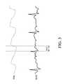
- FIG. 3explains pulse transit time
- FIG. 4is a flow chart of an exemplary embodiment of a biosignal measurement method of the invention.
- a biosignal measurement module 1comprises a biosignal detection unit 10 , a pose detection unit 11 , a processing unit 12 , a memory 13 , and a display unit 14 .
- FIG. 2is a schematic view showing the appearance of the biosignal measurement module 1 .
- the biosignal measurement module 1can operate in an initial parameter setting mode or a measurement mode.
- an external device 15is connected with an input port 20 of the biosignal measurement module 1 .
- the external device 15can be a known blood pressure meter, such as a digital bladder blood pressure meter.
- the external device 15measures, for several seconds, the average diastolic pressure and average systolic pressure of a subject and inputs the measured average diastolic pressure and average systolic pressure to the memory 13 through the input port 20 , which serve as an initial diastolic pressure DBP 0 and an initial systolic pressure SBP 0 , respectively.
- the biosignal measurement module 1comprises three detection electrodes 21 - 23 and one photo detector 24 .
- Three fingers of the subjectrespectively contact the detection electrodes 21 - 23 to retrieve an electrocardiogram signal.
- the forefinger of the left hand of the subjectcontacts the detection electrode 23
- the thumb of the left hand thereofcontacts the detection electrode 21
- the thumb of the right hand thereofcontacts the detection electrode 22 .
- the photo detector 24 for detecting a pulse signal of the subjectcan be combined with the detection electrode 23 .
- the forefinger of the left hand of the subjectcontacts both of the detection electrode 23 and the photo detector 24 .
- the biosignal measurement unit 10 of the biosignal measurement module 1measures an electrocardiogram signal and a pulse signal of the subject with the detection electrodes 21 - 23 and the photo detector 24 , and the measured electrocardiogram signal and the measured pulse signal serve as an initial electrocardiogram signal ECG 0 and an initial pulse signal PPG 0 .
- the processing unit 12receives the initial electrocardiogram signal ECG 0 and the initial pulse signal PPG 0 and calculates a pulse transit time (PTT) according to the initial electrocardiogram signal ECG 0 and the initial pulse signal PPG 0 .
- PTTpulse transit time
- the pulse transit timeis time difference between an electrocardiogram signal ECG and a pulse signal PPG, as shown in FIG. 3 .
- the processing unit 12obtains, during several seconds, a plurality of pulse transit time values and averages the pulse transit time values to obtain an initial pulse transit time PTT 0 .
- Equation (1)the relationship constant K relates to the initial systolic pressure SBP 0 and the initial pulse transit time PTT 0 .
- the pose detection unit 11measures an initial height difference H 0 between the biosignal measurement module 1 and the heart of the subject.
- the pose detection unit 11obtains gravity (G) components in the X axis, Y axis, and Z axis according to the position of the biosignal measurement module 1 to generate corresponding initial position signals; that is, X 0 , Y 0 , and Z 0 signals.
- the processing unit 12calculates the incline angle ⁇ 0 of the lower arm of the subject according to the Y 0 signal and the Z 0 signal as shown in Equation (2):
- L 0represents the height between the heart and the shoulders of the subject
- L 1represents the length of the upper arm of the subject
- L 2represent the length of the lower arm of the subject.
- the subjectcan input his height by an input unit (not shown) of the biosignal measurement module 1 in advance.
- the processing unit 12calculates the values L 0 , L 1 , and L 2 by applying the height into the standard body proportion equation and stores the obtained values L 0 , L 1 , and L 2 into the memory 13 .
- the processing unit 12When the processing unit 12 completes the calculation of the initial pulse transit time PTT 0 , the relationship constant K, and the initial height difference H 0 , the processing unit 12 transmits the initial parameters to the memory 13 for storage. After the initial parameter setting mode is completed, the memory 13 stores the initial parameters required for individual blood pressure correction comprising the initial diastolic pressure DBP 0 , the initial systolic pressure SBP 0 , the initial pulse transit time PTT 0 , the relationship constant K, and the initial height difference H 0 . Afterward, the external device 15 can be disconnected with the input port 20 .
- the biosignal measurement module 1enters the measurement mode if the subject desires to measure a blood pressure signal.
- the same figures of the subjectthat is the forefinger and thumb of the left hand and the thumb of the right hand
- the detection electrodes 21 - 23respectively.
- the forefinger of the left handalso contacts the photo detector 24 .
- the biosignal measurement unit 10measures the current electrocardiogram signal ECG N and the current pulse signal PPG N through the detection electrodes 21 - 23 and the photo detector 24 at the same time.
- the processing unit 12receives the current electrocardiogram signal ECG N and the current pulse signal PPG N and calculates the current pulse transit time PTT N according to the current electrocardiogram signal ECG N and the current pulse signal PPG N .
- the pose detection unit 11detects the height difference H N between the biosignal measurement module 1 and the heart of the subject. Similarly, the pose detection unit 11 obtains gravity (G) components in the X axis, Y axis, and Z axis according to the position of the biosignal measurement module 1 to generate corresponding initial position signals; that is X N , Y N , and Z N signals.
- the processing unit 12calculates the incline angle ⁇ N of the lower arm of the subject according to the Y N signal and the Z N signal as shown in Equation (4):
- the processing unit 12After obtaining the height difference H N between the biosignal measurement module 1 and the heart of the subject, according to the height difference H 0 of the initial parameter setting mode (read from the memory 13 ) and the height difference H N of the measurement mode, the processing unit 12 calculates and obtains the height difference ⁇ H between the position of the biosignal measurement module 1 in the initial parameter setting mode and that in the measurement mode.
- the height difference ⁇ Hserves as a height variation parameter.
- the position of the biosignal measurement module 1 in the initial parameter setting moderefers to a reference position
- the processing unit 12calculates the height difference ⁇ H (height variation parameter) between the position of the biosignal measurement module and the reference position according to the Y N signal and the Z N signal.
- the processing unit 12compensates for the current pulse transit time PTT N according to the height variation parameter ⁇ H to obtain a compensated pulse transit time PTT C , as shown in Equation (6):
- the processing unit 12reads the initial diastolic pressure DBP 0 , the initial systolic pressure SBP 0 , and the initial pulse transit time PTT 0 and calculates a diastolic pressure value DBP C of the blood pressure signal according to the systolic pressure value SBP C , the initial diastolic pressure DBP 0 , the initial systolic pressure SBP 0 , the initial pulse transit time PTT 0 , and the compensated pulse transit time PTT C , as shown in Equation (8):
- the height difference ⁇ H(height variation parameter) is calculated by the pose detection unit 11 .
- the current pulse transit time PTT Nis then compensated according to the height variation parameter ⁇ H for precisely calculating the diastolic pressure value and the systolic pressure value, which avoids blood pressure errors caused by the position change of the lower arm of the subject.
- the biosignal measurement module 1it is not necessary for the biosignal measurement module 1 to enter the initial parameter setting mode every time before it enters the measurement mode.
- the memory 13has stored the initial parameters, the subject can measure the blood pressure with the biosignal measurement module 1 at any time. If it is necessary or measurement is required at every predetermined interval, the external device 15 may connected with the biosignal measurement module 1 and the biosignal measurement module 1 enters initial parameter setting mode.
- the biosignal measurement module 1 of the embodimentcan be integrated in a personal digital assistant (PDA), a mobile phone, a digital camera, a global positioning system, or any other portable electronic equipment.
- PDApersonal digital assistant
- mobile phonea mobile phone
- digital cameraa digital camera
- global positioning systema global positioning system
- the pose detection unit 11can be implemented by an accelerator, a gyroscope, or a magnetometer.
- the biosignal measurement module 1further comprises a display unit 14 .
- the display unit 14can receive the initial diastolic pressure DBP 0 , the initial systolic pressure SBP 0 , the initial pulse transit time PTT 0 , the relationship, and/or the initial height difference H 0 from the memory 13 .
- the display unit 14can also receive the height variation parameter ⁇ H, the compensated pulse transit time PTT C , the systolic pressure value SBP C , and/or the diastolic pressure value DBP C which are calculated by the processing unit 12 .
- the display unit 14shows the subject the received parameters or signals by a display panel 140 .
- the photo detector 24can be combined with one of the detection electrodes 21 - 23 , for example, the photo detector 24 is combined with the detection electrode 23 . In other embodiments, the position of the photo detector 24 is close to the position of the detection electrode 23 .
- FIG. 4is a flow chart of an exemplary embodiment of a biosignal measurement method of the invention.
- the current electrocardiogram signal ECG N and the current pulse signal PPG N of the subjectare measured by the detection electrodes 21 - 23 and the photo detector 24 of the biosignal measurement module 1 (step S 40 ).
- the processing unit 12measures the height between the position of the biosignal measurement module 1 and the reference position to generate a height variation parameter ⁇ H (step S 41 ).
- the processing unit 12calculates the current pulse transit time PTT N according to the current electrocardiogram signal ECG N and the current pulse signal PPG N (step S 42 ).
- the processing unit 12compensates the current pulse transit time PTT N according to the height variation parameter ⁇ H to obtain the compensated pulse transit time PTT C , as shown in Equation (6) (step S 43 ).
- the initial diastolic pressure DBP 0 and the initial systolic pressure SBP 0are provided by the external device 15
- the initial pulse transit time PTT 0 and the relationship constant K which are stored in advanceare provided by the memory 13 (step S 44 ).
- the operation of the external device 15 for measuring the initial diastolic pressure DBP 0 and the initial systolic pressure SBP 0 and the obtainment of the initial pulse transit time PTT 0 and the relationship constant Kare the same as the above described embodiment of FIG. 1 .
- the processing unit 12calculates the systolic pressure value SBP C of the blood pressure signal according to the compensated pulse transit time PTT C and the relationship constant K, as shown in Equation (7) (step S 45 ). After the systolic pressure value SBP C is obtained, the processing unit 12 calculates the diastolic pressure value DBP C of the blood pressure signal according to the systolic pressure value SBP C , the initial diastolic pressure DBP 0 , the initial systolic pressure SBP 0 , and the initial pulse transit time PTT 0 , as shown in Equation (8) (step S 46 ).
- step S 44is not limited to follow the step S 43 .
- the operation of step S 44must be completed before the step S 45 .
Landscapes
- Health & Medical Sciences (AREA)
- Life Sciences & Earth Sciences (AREA)
- Physics & Mathematics (AREA)
- Biomedical Technology (AREA)
- Medical Informatics (AREA)
- Biophysics (AREA)
- Pathology (AREA)
- Engineering & Computer Science (AREA)
- Veterinary Medicine (AREA)
- Heart & Thoracic Surgery (AREA)
- Public Health (AREA)
- Molecular Biology (AREA)
- Surgery (AREA)
- Animal Behavior & Ethology (AREA)
- General Health & Medical Sciences (AREA)
- Optics & Photonics (AREA)
- Spectroscopy & Molecular Physics (AREA)
- Cardiology (AREA)
- Measuring Pulse, Heart Rate, Blood Pressure Or Blood Flow (AREA)
Abstract
Description
K=SBP0×PTT0 Equation (1).
H0=L0−L1+L2sin θ0 Equation (3),
HN=L0−L1+L2sin θN Equation (5).
SBPC=K[PTTC]−1 Equation (7).
Claims (21)
Applications Claiming Priority (3)
| Application Number | Priority Date | Filing Date | Title |
|---|---|---|---|
| TW97150199 | 2008-12-23 | ||
| TW097150199ATWI425934B (en) | 2008-12-23 | 2008-12-23 | Biosignal measurement modules and methods |
| TW97150199A | 2008-12-23 |
Publications (2)
| Publication Number | Publication Date |
|---|---|
| US20100160793A1 US20100160793A1 (en) | 2010-06-24 |
| US8239009B2true US8239009B2 (en) | 2012-08-07 |
Family
ID=42267137
Family Applications (1)
| Application Number | Title | Priority Date | Filing Date |
|---|---|---|---|
| US12/421,870Active2030-12-10US8239009B2 (en) | 2008-12-23 | 2009-04-10 | Biosignal measurement modules and methods |
Country Status (2)
| Country | Link |
|---|---|
| US (1) | US8239009B2 (en) |
| TW (1) | TWI425934B (en) |
Cited By (1)
| Publication number | Priority date | Publication date | Assignee | Title |
|---|---|---|---|---|
| CN105083042A (en)* | 2014-05-15 | 2015-11-25 | 福特全球技术公司 | Electric vehicle operation to manage battery capacity |
Families Citing this family (41)
| Publication number | Priority date | Publication date | Assignee | Title |
|---|---|---|---|---|
| US11607152B2 (en) | 2007-06-12 | 2023-03-21 | Sotera Wireless, Inc. | Optical sensors for use in vital sign monitoring |
| US8602997B2 (en) | 2007-06-12 | 2013-12-10 | Sotera Wireless, Inc. | Body-worn system for measuring continuous non-invasive blood pressure (cNIBP) |
| US11330988B2 (en) | 2007-06-12 | 2022-05-17 | Sotera Wireless, Inc. | Body-worn system for measuring continuous non-invasive blood pressure (cNIBP) |
| US12245852B2 (en) | 2007-06-12 | 2025-03-11 | Sotera Wireless, Inc. | Optical sensors for use in vital sign monitoring |
| WO2008154643A1 (en) | 2007-06-12 | 2008-12-18 | Triage Wireless, Inc. | Vital sign monitor for measuring blood pressure using optical, electrical, and pressure waveforms |
| US10973414B2 (en) | 2009-05-20 | 2021-04-13 | Sotera Wireless, Inc. | Vital sign monitoring system featuring 3 accelerometers |
| US8956293B2 (en) | 2009-05-20 | 2015-02-17 | Sotera Wireless, Inc. | Graphical ‘mapping system’ for continuously monitoring a patient's vital signs, motion, and location |
| US11896350B2 (en) | 2009-05-20 | 2024-02-13 | Sotera Wireless, Inc. | Cable system for generating signals for detecting motion and measuring vital signs |
| US9775529B2 (en) | 2009-06-17 | 2017-10-03 | Sotera Wireless, Inc. | Body-worn pulse oximeter |
| US8545417B2 (en) | 2009-09-14 | 2013-10-01 | Sotera Wireless, Inc. | Body-worn monitor for measuring respiration rate |
| US11253169B2 (en) | 2009-09-14 | 2022-02-22 | Sotera Wireless, Inc. | Body-worn monitor for measuring respiration rate |
| US12121364B2 (en) | 2009-09-14 | 2024-10-22 | Sotera Wireless, Inc. | Body-worn monitor for measuring respiration rate |
| US8527038B2 (en) | 2009-09-15 | 2013-09-03 | Sotera Wireless, Inc. | Body-worn vital sign monitor |
| US20110066044A1 (en) | 2009-09-15 | 2011-03-17 | Jim Moon | Body-worn vital sign monitor |
| US12156743B2 (en) | 2009-09-15 | 2024-12-03 | Sotera Wireless, Inc. | Body-worn vital sign monitor |
| US8321004B2 (en) | 2009-09-15 | 2012-11-27 | Sotera Wireless, Inc. | Body-worn vital sign monitor |
| US10806351B2 (en) | 2009-09-15 | 2020-10-20 | Sotera Wireless, Inc. | Body-worn vital sign monitor |
| US10420476B2 (en) | 2009-09-15 | 2019-09-24 | Sotera Wireless, Inc. | Body-worn vital sign monitor |
| US8364250B2 (en) | 2009-09-15 | 2013-01-29 | Sotera Wireless, Inc. | Body-worn vital sign monitor |
| US20110224499A1 (en) | 2010-03-10 | 2011-09-15 | Sotera Wireless, Inc. | Body-worn vital sign monitor |
| US8888700B2 (en) | 2010-04-19 | 2014-11-18 | Sotera Wireless, Inc. | Body-worn monitor for measuring respiratory rate |
| US8747330B2 (en) | 2010-04-19 | 2014-06-10 | Sotera Wireless, Inc. | Body-worn monitor for measuring respiratory rate |
| US9339209B2 (en) | 2010-04-19 | 2016-05-17 | Sotera Wireless, Inc. | Body-worn monitor for measuring respiratory rate |
| US9173594B2 (en) | 2010-04-19 | 2015-11-03 | Sotera Wireless, Inc. | Body-worn monitor for measuring respiratory rate |
| US9173593B2 (en) | 2010-04-19 | 2015-11-03 | Sotera Wireless, Inc. | Body-worn monitor for measuring respiratory rate |
| US8979765B2 (en) | 2010-04-19 | 2015-03-17 | Sotera Wireless, Inc. | Body-worn monitor for measuring respiratory rate |
| US10722132B2 (en) | 2010-12-28 | 2020-07-28 | Sotera Wireless, Inc. | Body-worn system for continuous, noninvasive measurement of cardiac output, stroke volume, cardiac power, and blood pressure |
| SG10201601161YA (en) | 2011-02-18 | 2016-03-30 | Sotera Wireless Inc | Optical sensor for measuring physiological properties |
| SG10201601164SA (en) | 2011-02-18 | 2016-03-30 | Sotera Wireless Inc | Modular wrist-worn processor for patient monitoring |
| US9693697B2 (en) | 2012-03-29 | 2017-07-04 | Benny Tal | Hand-held device having health monitoring capabilities |
| US20140031646A1 (en)* | 2012-03-29 | 2014-01-30 | Sergey Yakirevich | Blood pressure estimation using a hand-held device |
| EP2913642B1 (en)* | 2012-10-24 | 2021-03-17 | National Institute of Advanced Industrial Science and Technology | Mass flowmeter |
| US10478075B2 (en) | 2013-10-25 | 2019-11-19 | Qualcomm Incorporated | System and method for obtaining bodily function measurements using a mobile device |
| US10052035B2 (en) | 2013-10-25 | 2018-08-21 | Qualcomm Incorporated | System and method for obtaining bodily function measurements using a mobile device |
| TWI608826B (en) | 2014-10-31 | 2017-12-21 | 財團法人工業技術研究院 | Optical sensing device and measurement method thereof |
| US10201312B2 (en)* | 2014-12-08 | 2019-02-12 | Intel Corporation | Opportunistic measurements and processing of user's context |
| KR101778845B1 (en)* | 2015-07-14 | 2017-09-14 | 울산대학교 산학협력단 | Apparatus for calculating systolic blood pressure using the pulse transit time and method thereof |
| JP6824790B2 (en)* | 2017-03-15 | 2021-02-03 | オムロン株式会社 | Blood pressure measurement system and height correction method using height correction device and height correction device |
| WO2020154835A1 (en)* | 2019-01-28 | 2020-08-06 | 华为技术有限公司 | Method and device for measurement compensation |
| IT202000010813A1 (en)* | 2020-05-13 | 2021-11-13 | Biondi Eng S A | Device with two contact surfaces for the acquisition of biometric data, diagnostic system and method using the device, in particular for the diagnosis of viral infection |
| CN115998272B (en)* | 2023-03-16 | 2023-06-23 | 广东百年医疗健康科技发展有限公司 | Blood pressure estimating device, device and storage medium of PPG blood pressure monitoring device |
Citations (16)
| Publication number | Priority date | Publication date | Assignee | Title |
|---|---|---|---|---|
| US5865755A (en) | 1996-10-11 | 1999-02-02 | Dxtek, Inc. | Method and apparatus for non-invasive, cuffless, continuous blood pressure determination |
| TW389687B (en) | 1998-06-29 | 2000-05-11 | Ind Tech Res Inst | Methods and apparatus eliminating noise caused by artificial action during automatic blood pressure monitoring |
| US6120459A (en) | 1999-06-09 | 2000-09-19 | Nitzan; Meir | Method and device for arterial blood pressure measurement |
| US6186953B1 (en) | 1998-10-29 | 2001-02-13 | Colin Corporation | Non-invasive and continuous blood-pressure estimation apparatus |
| US6413223B1 (en) | 1999-06-01 | 2002-07-02 | Massachussetts Institute Of Technology | Cuffless continuous blood pressure monitor |
| US20030135127A1 (en)* | 2000-04-17 | 2003-07-17 | Vivometrics, Inc. | Systems and methods for ambulatory monitoring of physiological signs |
| US6599251B2 (en) | 2000-01-26 | 2003-07-29 | Vsm Medtech Ltd. | Continuous non-invasive blood pressure monitoring method and apparatus |
| US6648828B2 (en) | 2002-03-01 | 2003-11-18 | Ge Medical Systems Information Technologies, Inc. | Continuous, non-invasive technique for measuring blood pressure using impedance plethysmography |
| TW590761B (en) | 2003-07-24 | 2004-06-11 | K Jump Health Co Ltd | Non-invasive pumpless micro-airbag type device for measuring blood pressure and pulse and method for using such a device |
| TWM242184U (en) | 2003-01-30 | 2004-09-01 | Unisage Digital Co Ltd | Personalized ECG transmission device |
| US6872182B2 (en) | 2000-11-14 | 2005-03-29 | Omron Corporation | Electronic sphygmomanometer |
| US6893401B2 (en) | 2001-07-27 | 2005-05-17 | Vsm Medtech Ltd. | Continuous non-invasive blood pressure monitoring method and apparatus |
| US20050261593A1 (en)* | 2004-05-20 | 2005-11-24 | Zhang Yuan T | Methods for measuring blood pressure with automatic compensations |
| TWI268773B (en) | 2005-02-02 | 2006-12-21 | Tsair Kao | Method for detecting continuous blood pressure waveform |
| US20070055163A1 (en)* | 2005-08-22 | 2007-03-08 | Asada Haruhiko H | Wearable blood pressure sensor and method of calibration |
| US20070142730A1 (en)* | 2005-12-13 | 2007-06-21 | Franz Laermer | Apparatus for noninvasive blood pressure measurement |
- 2008
- 2008-12-23TWTW097150199Apatent/TWI425934B/enactive
- 2009
- 2009-04-10USUS12/421,870patent/US8239009B2/enactiveActive
Patent Citations (16)
| Publication number | Priority date | Publication date | Assignee | Title |
|---|---|---|---|---|
| US5865755A (en) | 1996-10-11 | 1999-02-02 | Dxtek, Inc. | Method and apparatus for non-invasive, cuffless, continuous blood pressure determination |
| TW389687B (en) | 1998-06-29 | 2000-05-11 | Ind Tech Res Inst | Methods and apparatus eliminating noise caused by artificial action during automatic blood pressure monitoring |
| US6186953B1 (en) | 1998-10-29 | 2001-02-13 | Colin Corporation | Non-invasive and continuous blood-pressure estimation apparatus |
| US6413223B1 (en) | 1999-06-01 | 2002-07-02 | Massachussetts Institute Of Technology | Cuffless continuous blood pressure monitor |
| US6120459A (en) | 1999-06-09 | 2000-09-19 | Nitzan; Meir | Method and device for arterial blood pressure measurement |
| US6599251B2 (en) | 2000-01-26 | 2003-07-29 | Vsm Medtech Ltd. | Continuous non-invasive blood pressure monitoring method and apparatus |
| US20030135127A1 (en)* | 2000-04-17 | 2003-07-17 | Vivometrics, Inc. | Systems and methods for ambulatory monitoring of physiological signs |
| US6872182B2 (en) | 2000-11-14 | 2005-03-29 | Omron Corporation | Electronic sphygmomanometer |
| US6893401B2 (en) | 2001-07-27 | 2005-05-17 | Vsm Medtech Ltd. | Continuous non-invasive blood pressure monitoring method and apparatus |
| US6648828B2 (en) | 2002-03-01 | 2003-11-18 | Ge Medical Systems Information Technologies, Inc. | Continuous, non-invasive technique for measuring blood pressure using impedance plethysmography |
| TWM242184U (en) | 2003-01-30 | 2004-09-01 | Unisage Digital Co Ltd | Personalized ECG transmission device |
| TW590761B (en) | 2003-07-24 | 2004-06-11 | K Jump Health Co Ltd | Non-invasive pumpless micro-airbag type device for measuring blood pressure and pulse and method for using such a device |
| US20050261593A1 (en)* | 2004-05-20 | 2005-11-24 | Zhang Yuan T | Methods for measuring blood pressure with automatic compensations |
| TWI268773B (en) | 2005-02-02 | 2006-12-21 | Tsair Kao | Method for detecting continuous blood pressure waveform |
| US20070055163A1 (en)* | 2005-08-22 | 2007-03-08 | Asada Haruhiko H | Wearable blood pressure sensor and method of calibration |
| US20070142730A1 (en)* | 2005-12-13 | 2007-06-21 | Franz Laermer | Apparatus for noninvasive blood pressure measurement |
Cited By (1)
| Publication number | Priority date | Publication date | Assignee | Title |
|---|---|---|---|---|
| CN105083042A (en)* | 2014-05-15 | 2015-11-25 | 福特全球技术公司 | Electric vehicle operation to manage battery capacity |
Also Published As
| Publication number | Publication date |
|---|---|
| TWI425934B (en) | 2014-02-11 |
| US20100160793A1 (en) | 2010-06-24 |
| TW201023823A (en) | 2010-07-01 |
Similar Documents
| Publication | Publication Date | Title |
|---|---|---|
| US8239009B2 (en) | Biosignal measurement modules and methods | |
| US11219375B2 (en) | Method and device for detecting blood pressure calibration time point | |
| US9326692B2 (en) | Blood pressure measurement device and blood pressure measurement method | |
| US10729338B2 (en) | Blood pressure measurement device and calibration method thereof | |
| US8795185B2 (en) | Portable device for measuring blood pressure and method therefor | |
| US9176141B2 (en) | Physiological monitor calibration system | |
| US7742808B2 (en) | Heart rate monitor, method and computer software product | |
| US20190059752A1 (en) | Method and apparatus for cuff less blood pressure monitoring based on simultaneously measured ECG and PPG signals designed in wristband form for continuous wearing | |
| EP3524137B1 (en) | Calibration method for blood pressure measuring device, and blood pressure measuring device | |
| US11266357B2 (en) | Bio-signal feature scaling apparatus and method | |
| US20070265514A1 (en) | Systems and methods for calibrating minimally invasive and non-invasive physiological sensor devices | |
| CN101810470A (en) | Physiological signal measurement module and method | |
| US20100222650A1 (en) | Biological signal measuring apparatus | |
| US9918645B2 (en) | Method and apparatus for measuring change in blood pressure by respiration control | |
| KR20170067131A (en) | Blood presure measurement apparatus and blood presure measuring method using the same | |
| US20200237240A1 (en) | Vital-sign estimation apparatus and calibration method for vital-sign estimator | |
| CN109833037B (en) | Equipment for monitoring blood pressure state and computer readable storage medium | |
| US20130041270A1 (en) | Blood pressure measuring device and system with automatic self-examination and self-calibration functions | |
| JP6593176B2 (en) | Blood pressure correction information generation device, blood pressure measurement device, blood pressure correction information generation method, blood pressure correction information generation program | |
| US20150320327A1 (en) | Hemodynamics measurement apparatus and hemodynamics measurement method | |
| US20230404416A1 (en) | A method and a device for calibrating a blood pressure estimation model for determining tonoarteriogram signals | |
| US20070010749A1 (en) | Diagnostic device and the method using the same | |
| CN119235281B (en) | Blood pressure detection method and device | |
| US20140364747A1 (en) | Method for measuring blood pressure, and apparatus for measuring blood pressure based on said method | |
| US20240366095A1 (en) | Technologies for multimodal sensor wearable device for biomedical monitoring |
Legal Events
| Date | Code | Title | Description |
|---|---|---|---|
| AS | Assignment | Owner name:INDUSTRIAL TECHNOLOGY RESEARCH INSTITUTE,TAIWAN Free format text:ASSIGNMENT OF ASSIGNORS INTEREST;ASSIGNORS:LEE, WEN-CHING;HUANG, TSUN-CHE;KO, CHIH-HSIANG;REEL/FRAME:022533/0317 Effective date:20090326 Owner name:INDUSTRIAL TECHNOLOGY RESEARCH INSTITUTE, TAIWAN Free format text:ASSIGNMENT OF ASSIGNORS INTEREST;ASSIGNORS:LEE, WEN-CHING;HUANG, TSUN-CHE;KO, CHIH-HSIANG;REEL/FRAME:022533/0317 Effective date:20090326 | |
| STCF | Information on status: patent grant | Free format text:PATENTED CASE | |
| FPAY | Fee payment | Year of fee payment:4 | |
| MAFP | Maintenance fee payment | Free format text:PAYMENT OF MAINTENANCE FEE, 8TH YEAR, LARGE ENTITY (ORIGINAL EVENT CODE: M1552); ENTITY STATUS OF PATENT OWNER: LARGE ENTITY Year of fee payment:8 | |
| MAFP | Maintenance fee payment | Free format text:PAYMENT OF MAINTENANCE FEE, 12TH YEAR, LARGE ENTITY (ORIGINAL EVENT CODE: M1553); ENTITY STATUS OF PATENT OWNER: LARGE ENTITY Year of fee payment:12 |