US8237767B2 - System and method for screening video communications within an interactive television system - Google Patents
System and method for screening video communications within an interactive television systemDownload PDFInfo
- Publication number
- US8237767B2 US8237767B2US12/417,408US41740809AUS8237767B2US 8237767 B2US8237767 B2US 8237767B2US 41740809 AUS41740809 AUS 41740809AUS 8237767 B2US8237767 B2US 8237767B2
- Authority
- US
- United States
- Prior art keywords
- caller
- recipient
- video
- communication request
- video communication
- Prior art date
- Legal status (The legal status is an assumption and is not a legal conclusion. Google has not performed a legal analysis and makes no representation as to the accuracy of the status listed.)
- Expired - Fee Related, expires
Links
Images


Classifications
- H—ELECTRICITY
- H04—ELECTRIC COMMUNICATION TECHNIQUE
- H04L—TRANSMISSION OF DIGITAL INFORMATION, e.g. TELEGRAPHIC COMMUNICATION
- H04L65/00—Network arrangements, protocols or services for supporting real-time applications in data packet communication
- H04L65/1066—Session management
- H04L65/1069—Session establishment or de-establishment
- H—ELECTRICITY
- H04—ELECTRIC COMMUNICATION TECHNIQUE
- H04L—TRANSMISSION OF DIGITAL INFORMATION, e.g. TELEGRAPHIC COMMUNICATION
- H04L65/00—Network arrangements, protocols or services for supporting real-time applications in data packet communication
- H04L65/1066—Session management
- H04L65/1101—Session protocols
- H—ELECTRICITY
- H04—ELECTRIC COMMUNICATION TECHNIQUE
- H04N—PICTORIAL COMMUNICATION, e.g. TELEVISION
- H04N21/00—Selective content distribution, e.g. interactive television or video on demand [VOD]
- H04N21/20—Servers specifically adapted for the distribution of content, e.g. VOD servers; Operations thereof
- H04N21/25—Management operations performed by the server for facilitating the content distribution or administrating data related to end-users or client devices, e.g. end-user or client device authentication, learning user preferences for recommending movies
- H04N21/254—Management at additional data server, e.g. shopping server, rights management server
- H—ELECTRICITY
- H04—ELECTRIC COMMUNICATION TECHNIQUE
- H04N—PICTORIAL COMMUNICATION, e.g. TELEVISION
- H04N21/00—Selective content distribution, e.g. interactive television or video on demand [VOD]
- H04N21/20—Servers specifically adapted for the distribution of content, e.g. VOD servers; Operations thereof
- H04N21/25—Management operations performed by the server for facilitating the content distribution or administrating data related to end-users or client devices, e.g. end-user or client device authentication, learning user preferences for recommending movies
- H04N21/258—Client or end-user data management, e.g. managing client capabilities, user preferences or demographics, processing of multiple end-users preferences to derive collaborative data
- H04N21/25866—Management of end-user data
- H04N21/25875—Management of end-user data involving end-user authentication
- H—ELECTRICITY
- H04—ELECTRIC COMMUNICATION TECHNIQUE
- H04N—PICTORIAL COMMUNICATION, e.g. TELEVISION
- H04N21/00—Selective content distribution, e.g. interactive television or video on demand [VOD]
- H04N21/40—Client devices specifically adapted for the reception of or interaction with content, e.g. set-top-box [STB]; Operations thereof
- H04N21/41—Structure of client; Structure of client peripherals
- H04N21/422—Input-only peripherals, i.e. input devices connected to specially adapted client devices, e.g. global positioning system [GPS]
- H04N21/4223—Cameras
- H—ELECTRICITY
- H04—ELECTRIC COMMUNICATION TECHNIQUE
- H04N—PICTORIAL COMMUNICATION, e.g. TELEVISION
- H04N21/00—Selective content distribution, e.g. interactive television or video on demand [VOD]
- H04N21/40—Client devices specifically adapted for the reception of or interaction with content, e.g. set-top-box [STB]; Operations thereof
- H04N21/41—Structure of client; Structure of client peripherals
- H04N21/426—Internal components of the client ; Characteristics thereof
- H04N21/42684—Client identification by a unique number or address, e.g. serial number, MAC address, socket ID
- H—ELECTRICITY
- H04—ELECTRIC COMMUNICATION TECHNIQUE
- H04N—PICTORIAL COMMUNICATION, e.g. TELEVISION
- H04N21/00—Selective content distribution, e.g. interactive television or video on demand [VOD]
- H04N21/40—Client devices specifically adapted for the reception of or interaction with content, e.g. set-top-box [STB]; Operations thereof
- H04N21/47—End-user applications
- H04N21/478—Supplemental services, e.g. displaying phone caller identification, shopping application
- H04N21/4788—Supplemental services, e.g. displaying phone caller identification, shopping application communicating with other users, e.g. chatting
- H—ELECTRICITY
- H04—ELECTRIC COMMUNICATION TECHNIQUE
- H04N—PICTORIAL COMMUNICATION, e.g. TELEVISION
- H04N7/00—Television systems
- H04N7/14—Systems for two-way working
- H04N7/141—Systems for two-way working between two video terminals, e.g. videophone
- H04N7/147—Communication arrangements, e.g. identifying the communication as a video-communication, intermediate storage of the signals
Definitions
- the present inventionrelates generally to the field of interactive television systems. More specifically, the present invention relates to a system and method for screening incoming and outgoing video communications within an interactive television system.
- Videoconferencingoffers a new dimension to traditional electronic communication, allowing participants to convey information more rapidly and completely than ever before.
- videoconferencingoffers a greater degree of intimacy than traditional audio-only communication, it has an increased capacity for misuse by irresponsible persons. For instance, some users may transmit lewd and/or offensive images through the video medium. Additionally, because videoconferencing is typically two-way, it may attract stalkers, pedophiles, and others with criminal intentions.
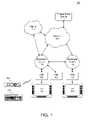
- FIG. 1is a block diagram of a system for two-way video communication
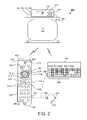
- FIG. 2is an illustration of an interactive television system
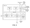
- FIG. 3is a block diagram of physical components of a set top box (STB);
- FIG. 4is a dataflow diagram of a first embodiment of the invention.
- FIG. 5is a dataflow diagram of a second embodiment of the invention.
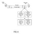
- FIG. 6is a dataflow diagram of a third embodiment of the invention.
- FIG. 7is a dataflow diagram of a fourth embodiment of the invention.
- FIG. 8is a dataflow diagram of a fifth embodiment of the invention.
- FIG. 9is a dataflow diagram of a sixth embodiment of the invention.
- FIG. 10is a block diagram of logical components of a system for screening incoming video communications
- FIG. 11is a block diagram of logical components of an alternative system for screening incoming video communications
- FIG. 12illustrates an unauthorized caller list and an authorized caller list
- FIG. 13illustrates a recipient-specific unauthorized caller list
- FIG. 14illustrates a user interface for third-party screening of video communication requests
- FIG. 15is a dataflow diagram of a seventh embodiment of the invention.
- FIG. 16is a dataflow diagram of an eighth embodiment of the invention.
- FIG. 17is a flowchart of a method for screening incoming video communications within an interactive television system
- FIG. 18is a dataflow diagram of a ninth embodiment of the invention.
- FIG. 19is a dataflow diagram of a tenth embodiment of the invention.
- FIG. 20is a dataflow diagram of an eleventh embodiment of the invention.
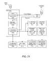
- FIG. 21is a dataflow diagram of an eleventh embodiment of the invention.
- the present inventionsolves the foregoing problems and disadvantages by providing a system and method for screening incoming and outgoing video communications within an interactive television system.
- a video communication requestis sent from a caller to a recipient (i.e. from a caller's system to a recipient's system).
- the identity of the callerwhich may be obtained from the request, is compared with those in an unauthorized caller list. If a match is found, the video communication request is rejected by default. Recipients on the unauthorized caller list may include, for example, previously offensive callers, callers known to be convicted felons, and the like. If no match is found, the video communication request may be accepted by default, subject to acceptance by the recipient. Rejected video communication requests may be recorded in a log for later review by the intended recipient or a parent or responsible party.
- the caller's identitymay be compared with those in an authorized caller list.
- the video communication requestmay be accepted only if the caller's identity is included within the authorized caller list. All other video communication requests may be rejected by default. This allows a parent or responsible party to limit video communications to a set of pre-screened individuals, which also has the effect of screening out video communication requests from telemarketers and other unknown parties.
- screeningmay occur within a set top box (STB) used by the recipient.
- screeningmay occur at an intermediate node of a communications network linking STBs associated with the caller and the recipient.
- the unauthorized caller list and/or the authorized caller listmay be recipient-specific.
- Recipient-specific listsoperate like the general lists described above, but are applicable only to a particular recipient.
- recipient-specific listsmay be combined, in certain embodiments, with general authorized/unauthorized caller lists, allowing a parent or guardian to specify, for example, restricted callers for the family, as well as restricted callers for individual family members.
- the video communication requestis intercepted and a third party (e.g., parent or responsible person) is prompted to accept or reject the request.
- the third partymay be provided with the identities of the caller and the recipient to assist in the determination. If the third party accepts the request, the communication may be allowed to proceed; otherwise, the request is rejected.
- the identity of the callermay be added to a general or recipient-specific unauthorized caller list.
- the identity of the callermay be added to a general or recipient-specific authorized caller list.
- the third partymay be at a remote location when the video communication request is received.
- a parentmay be at work while the request is received by a home STB. Accordingly, the third party may be prompted to accept or reject the communication at a remote location.
- temporary video communicationmay be established between the caller and the third party to allow the third party to inquire as to the nature and purpose of the communication.
- the requestmay include live video from the caller to assist the third party in making a determination. Where live video from the caller is not available, or where the caller is not willing or able to establish two-way video communication with the third party, the request may be rejected by default.
- Third-party screeningmay be combined with screening using an authorized caller list, an unauthorized caller list, and/or recipient-specific authorized/unauthorized caller lists. For example, callers not found on an unauthorized caller list may not be automatically rejected. Instead, a third party may be prompted to accept or reject the caller.
- a notificationmay be automatically sent to a law enforcement agency.
- the notificationmay identify the caller as well as other details concerning the unwanted video communication requests.
- outgoing video communication requestsare also screened using similar techniques. For example, the identity of the recipient may be obtained and compared with those in an unauthorized recipient list, similar to the unauthorized caller list described above. If the recipient is found in the unauthorized recipient list, the request may be blocked by default (e.g., not forwarded to the recipient). Alternatively, if the recipient is not found in the list, the request may be forwarded to the recipient for rejection or acceptance.
- Various other listsmay be provided, such as authorized recipient lists, which are used in the same manner as the authorized caller lists previously described. Any of these lists may be caller-specific, to allow different lists for different callers. Also, third-party screening may be provided for outgoing video calls in the same manner that third-party screening is provided for incoming calls.
- a system and method in accordance with the present inventionallows users to adopt the latest video communications capabilities of modern video communication systems without fear of exposing their households or offices to the increased dangers associated with videoconferencing.
- videoconferencingtypically involves two-way audio communication.
- components for video communicationare specifically illustrated, components for audio communication may also be included.
- the system 100uses a broadband network 101 for communication, such as a cable network or a direct satellite broadcast (DBS) network.
- a broadband network 101 for communicationsuch as a cable network or a direct satellite broadcast (DBS) network.
- DBSdirect satellite broadcast
- the system 100includes a plurality of set top boxes (STBs) 102 located, for instance, at customer homes or offices.
- STBsset top boxes
- an STB 102is a consumer electronics device that serves as a gateway between a customer's television 104 and the network 101 .
- an STB 102may be embodied more generally as a personal computer (PC), an advanced television 104 with STB functionality, or another type of client terminal.
- PCpersonal computer
- advanced television 104 with STB functionalityor another type of client terminal.
- An STB 102receives encoded television signals and other information from the network 101 and decodes the same for display on the television 104 or other display device (such as a computer monitor, flat panel display, or the like). As its name implies, an STB 102 is typically located on top of, or in close proximity to, the television 104 .
- Each STB 102may be distinguished from other network components by a unique identifier, number, code, or address, examples of which include an Internet Protocol (IP) address (such as an IPv6 address), a Media Access Control (MAC) address, or the like.
- IPInternet Protocol
- MACMedia Access Control
- a remote control 106is provided, in one configuration, for convenient remote operation of the STB 102 and the television 104 .
- the remote control 106may use infrared (IR), radio frequency (RF), or other wireless technologies to transmit control signals to the STB 102 and the television 104 .
- Other remote control devicesare also contemplated, such as a wired or wireless mouse (not shown).
- a keyboard 108(either wireless or wired) is provided, in one embodiment, to allow a user to rapidly enter text information into the STB 102 .
- text informationmay be used for e-mail, instant messaging (e.g. text-based chat), or the like.
- the keyboard 108may use infrared (IR), radio frequency (RF), or other wireless technologies to transmit keystroke data to the STB 102 .
- IRinfrared
- RFradio frequency
- Each STB 102may be coupled to the network 101 via a broadcast center 110 .
- a broadcast center 110may be embodied as a head-end, which is generally a centrally-located facility within a community where television programming is received from a local cable TV satellite downlink or other source and packaged together for transmission to customer homes.
- a head-endalso functions as a Central Office (CO) in the telephone industry, routing video streams and other data to and from the various STBs 102 serviced thereby.
- COCentral Office
- a broadcast center 110may also be embodied as a satellite broadcast center within a direct broadcast satellite (DBS) system.
- DBSdirect broadcast satellite
- a DBS systemmay utilize a small 18-inch satellite dish (which is an antenna for receiving a satellite broadcast signal).
- Each STB 102may be integrated with a digital integrated receiver/decoder (IRD), which separates each channel, and decompresses and translates the digital signal from the satellite dish to be displayed by the television 104 .
- ITDdigital integrated receiver/decoder
- Programming for a DBS systemmay be distributed, for example, by multiple high-power satellites in geosynchronous orbit, each with multiple transponders. Compression (e.g., MPEG) is used to increase the amount of programming that can be transmitted in the available bandwidth.
- Compressione.g., MPEG
- the broadcast centers 110may be used to gather programming content, ensure its digital quality, and transmit the signal up to the satellites.
- Programmingmay come to the broadcast centers 110 from content providers (CNN, ESPN, HBO, TBS, etc.) via satellite, fiber optic cable and/or special digital tape.
- Satellite-delivered programmingis typically immediately digitized, encrypted and uplinked to the orbiting satellites. The satellites retransmit the signal back down to every earth-station, e.g., every compatible DBS system receiver dish at customers' homes and businesses.
- Some programsmay be recorded on digital videotape in the broadcast center 110 to be broadcast later. Before any recorded programs are viewed by customers, technicians may use post-production equipment to view and analyze each tape to ensure audio and video quality. Tapes may then be loaded into a robotic tape handling systems, and playback may be triggered by a computerized signal sent from a broadcast automation system. Back-up videotape playback equipment may ensure uninterrupted transmission at all times.
- the broadcast centers 110may be coupled directly to one another or through the network 101 .
- broadcast centers 110may be connected via a separate network, one particular example of which is the Internet 112 .
- the Internet 112is a “network of networks” and is well known to those skilled in the art. Communication over the Internet 112 is accomplished using standard protocols, such as TCP/IP (Transmission Control Protocol/Internet Protocol) and the like.
- a broadcast center 110may receive television programming for distribution to the STBs 102 from one or more television programming sources 114 coupled to the network 101 .
- television programsare distributed in an encoded format, such as MPEG (Moving Picture Experts Group).
- MPEGMotion Picture Experts Group
- MPEG-2, MPEG-4, MPEG-7, and the likeare known, such as MPEG-2, MPEG-4, MPEG-7, and the like.
- MPEGMotion Picture Experts Group
- other video encoding/compression standardsexist other than MPEG, such as JPEG, JPEG-LS, H.261, and H.263. Accordingly, the invention should not be construed as being limited only to MPEG.
- Broadcast centers 110may enable audio and video communications between STBs 102 . Transmission between broadcast centers 110 may occur (i) via a direct peer-to-peer connection between broadcast centers 110 , (ii) upstream from a first broadcast center 110 to the network 101 and then downstream to a second broadcast center 110 , or (iii) via the Internet 112 . For instance, a first STB 102 may send a video transmission upstream to a first broadcast center 110 , then to a second broadcast center 110 , and finally downstream to a second STB 102 .
- the system 200may include an STB 102 , a television 104 (or other display device), a remote control 106 , and, in certain configurations, a keyboard 108 .
- the remote control 106is provided for convenient remote operation of the STB 102 and the television 104 .
- the remote control 106includes a wireless transmitter 202 for transmitting control signals (and possibly audio/video data) to a wireless receiver 203 within the STB 102 and/or the television 104 .
- the remote control 106also includes a wireless receiver 204 for receiving signals from a wireless transmitter 205 within the STB 102 .
- the wireless transmitters 202 , 205 and receivers 203 , 204are configured to use radio frequency (RF) signals. In other embodiments, infrared (IR) or other frequencies along the electromagnetic spectrum may be used. Operational details regarding the wireless transmitters 202 , 205 and receivers 203 , 204 are generally well known to those of skill in the art.
- the remote control 106preferably includes a number of buttons or other similar controls.
- the remote control 106may include a power button 206 , an up arrow button 208 , a down arrow button 210 , a left arrow button 212 , a right arrow button 214 , a “Select” button 216 , an “OK” button 218 , channel adjustment buttons 220 , volume adjustment buttons 222 , alphanumeric buttons 224 , a “Call” button 226 , and the like.
- the remote control 106includes a microphone 242 for capturing an audio signal.
- the captured audio signalis preferably transmitted to the STB 102 via the wireless transmitter 202 .
- the remote control 106may include a speaker 244 for generating audible output from an audio signal received from the STB 102 via the wireless receiver 204 .
- the microphone 242 and speaker 244may be integrated with the STB 102 .
- the remote control 106includes a video camera 246 , such as a CCD (charge-coupled device) digital video camera.
- the video camera 246allows a user to capture and send video signals to the STB 102 .
- the video camera 246may capture images of the user.
- the video camera 246is in electrical communication with the wireless transmitter 202 for sending the captured video signal to the STB 102 .
- the video camera 246may be integrated with the STB 102 in other embodiments.
- the various components of the remote control 106may be positioned in different locations for functionality and ergonomics.
- the speaker 244may be positioned near the “top” of the remote control 106 (when viewed from the perspective of FIG. 2 ) and the microphone 242 may be positioned at the “bottom” of the remote control 106 .
- a usermay conveniently position the speaker 244 near the user's ear and the microphone 242 near the user's mouth in order to operate the remote control 106 in the manner of a telephone.
- a hands-free headset 248may be coupled to the remote control 106 or keyboard 108 .
- the headset 248may be coupled using a standard headset jack 250 .
- the headset 248may include a microphone 242 and/or speaker 244 .
- Such a headset 248may be used to reduce audio interference from the television 104 (improving audio quality) and to provide the convenience of hands-free operation.
- the optional keyboard 108facilitates rapid composition of text messages.
- the keyboard 108includes a plurality of standard alphanumeric keys 236 .
- the keyboard 108includes a wireless transmitter 202 , similar or identical to the wireless transmitter 202 of the remote control 106 .
- the wireless transmitter 202transmits keystroke data from the keyboard 108 to the STB 102 .
- the keyboard 108may include one or more of the buttons illustrated on the remote control 106 .
- the STB 102includes a wireless receiver 203 and a wireless transmitter 205 for receiving/transmitting control signals from/to the remote control 106 .
- the STB 102also includes, in one implementation, a network interface 302 for communicating with the network 101 via the broadcast center 110 .
- the interface 302may include conventional circuitry for receiving, demodulating, and demultiplexing MPEG (Moving Picture Experts Group) packets.
- the interface 302may also include conventional cable modem circuitry for sending or receiving data.
- the interface 302may conform to the DOCSIS (Data Over Cable Service Interface Specification) or DAVIC (Digital Audio-Visual Council) cable modem standards.
- one or more frequency bandsmay be reserved for upstream transmission.
- Digital modulationfor example, quadrature amplitude modulation or vestigial sideband modulation
- upstream transmissionmay be accomplished differently for different networks 101 .
- Alternative ways to accomplish upstream transmissioninclude using a back channel transmission, which is typically sent via an analog telephone line, ISDN, DSL, or other techniques.
- the STB 102also preferably includes a codec (encoder/decoder) 304 , which serves to encode audio/video signals into a network-compatible data stream for transmission over the network 101 .
- the codec 304also serves to decode a network-compatible data stream received from the network 101 .
- the codec 304may be implemented in hardware and/or software. Moreover, the codec 304 may use various algorithms, such as MPEG or Voice over IP (VoIP), for encoding and decoding.
- the STB 102further includes a memory device 306 , such as a random access memory (RAM), for storing temporary data.
- a memory device 306such as a random access memory (RAM), for storing temporary data.
- ROMread-only memory
- storing more permanent datasuch as fixed code and configuration information.
- an audio/video (A/V) controller 308is provided for converting digital audio/video signals into analog signals for playback/display on the television 104 .
- the A/V controller 308may be implemented using one or more physical devices, such as a separate graphics and sound controllers.
- the A/V controller 308may include graphics hardware for performing bit-block transfers (bit-blits) and other graphical operations for displaying a graphical user interface (GUI) on the television 104 .
- bit-blitsbit-block transfers
- GUIgraphical user interface
- the STB 102may include a storage device 310 , such as a hard disk drive or the like.
- the storage device 310may be configured to store encoded television broadcasts and retrieve the same at a later time for display.
- the storage device 310may be configured, in one embodiment, as a digital video recorder (DVR), enabling scheduled recording of television programs, pausing (buffering) live video, etc.
- DVRdigital video recorder
- the storage device 310may also be used in various embodiments to store viewer preferences, parental lock settings, electronic program guide (EPG) data, passwords, e-mail messages, and the like.
- the storage device 310also stores an operating system (OS) for the STB 102 , such as Windows CE® or Linux®.
- OSoperating system
- the STB 102may include, in certain embodiments, a microphone 242 and a speaker 244 for capturing and reproducing audio signals, respectively.
- the STB 102may also include a video camera 246 for capturing video signals. These components may be included in lieu of or in addition to similar components in the remote control 106 , keyboard 108 , and/or television 104 .
- a CPU 312controls the operation of the STB 102 , including the other components thereof, which are coupled to the CPU 312 in one embodiment via a bus 314 .
- the CPU 312may be embodied as a microprocessor, a microcontroller, a digital signal processor (DSP) or other device known in the art. As noted above, the CPU 312 may perform logical and arithmetic operations based on program code stored within the memory 306 or the storage device 310 .
- FIG. 3illustrates only one possible configuration of an STB 102 .
- FIG. 3illustrates only one possible configuration of an STB 102 .
- Those skilled in the artwill recognize that various other architectures and components may be provided within the scope of the invention.
- various standard componentsare not illustrated in order to avoid obscuring aspects of the invention.
- FIGS. 4-9are high-level dataflow diagrams illustrating operations and transactions according to several embodiments of the invention.
- the illustrated embodimentsmay be combined in various ways without departing from the spirit and scope of the invention.
- a caller 402 at a first STB 102 amay attempt to establish video communication with a recipient 404 at a second STB 102 b .
- other devicesmay be used for video communication, such as video phones, PDAs, personal computers, and the like.
- the caller's STB 102 asends a video communication request to the recipient's STB 102 b .
- the precise format of the requestis not crucial to the invention and will vary depending on the particular hardware and software being used. Typically, however, the request will identify the caller 402 and the recipient 404 , e.g., by name, network address, or the like. In essence, the request is an invitation to the recipient 404 to establish video communication with the caller 402 .
- the requestis intercepted by the recipient's STB 102 b before the recipient 404 is notified of the request or before two-way video communication is established. Thereafter, the caller's identity is determined from information contained within the request. For example, the caller's name or network address may be extracted from the request.
- caller 402and “recipient 404 ” are synonymous with “the caller's identity” and the “recipient's identity”, respectively.
- the terms “caller 402 ” and “STB 102 a ”may also be synonymous, where a request only identifies a caller 402 by the name or address of the STB 102 a.
- the STB 102 bdetermines whether the caller 402 (i.e. the caller's identity) is included within an unauthorized caller list 406 .
- the unauthorized caller list 406is a list of callers 402 who are not allowed to communicate with the recipient 404 and/or other users of the STB 102 b .
- the unauthorized caller list 406may contain, for example, previously offensive callers 406 , callers 406 who are known felons, etc.
- the video communication requestmay be rejected by default. If the caller 402 is not in the unauthorized caller list 406 , the video communication request may be accepted, subject, of course, to acceptance by the recipient 404 .
- the caller 402 or the caller's STB 102 amay not be identified by the request.
- a caller 402may configure the STB 102 a to mask his or her identity.
- the requestis automatically rejected in one embodiment, since the STB 102 b is not capable of determining whether the caller 402 is a threat to the recipient 404 .
- the unauthorized caller list 406is administered by a parent or other responsible party.
- the recipient's STB 102 bmay provide an interface for adding, deleting, or modifying the callers 402 included in the unauthorized caller list 406 .
- Security measurese.g., passwords
- the unauthorized caller list 406provides an effective mechanism for screening a video communication request. Video communication requests from parties known to be potentially threatening to the recipient 404 may be automatically blocked by including those parties in the unauthorized caller list 406 .
- the recipient's STB 102 bmay include an authorized caller list 502 , which is a list of pre-screened callers 402 who are permitted to contact the recipient 404 .
- An authorized caller list 502is more restrictive than an unauthorized caller list 406 , since a request may be accepted only if the caller 402 is contained within the list 502 . This has the effect of screening out requests from unknown parties, such as telemarketers and the like.
- the aforementioned lists 406 , 502may be recipient-specific.
- an STB 102 bmay include a general unauthorized caller list 602 , similar to the list 406 of FIG. 4 , which applies to all recipients 404 .
- the STB 102 bmay include a recipient-specific unauthorized caller list 604 , which is only applicable to the recipient 404 .
- the recipient 404may be identified using information contained within the video communication request.
- a requestmay include an e-mail address, e.g., dave@myhome.net, which may identify both a destination STB 102 b , e.g., myhome.net, as well as a recipient 404 , e.g., dave.
- a unique identifiere.g., an IPv6 address, may be used to uniquely identify each recipient 404 .
- a general authorized caller list 606(similar to the list 502 of FIG. 5 ) and/or a recipient-specific authorized caller list 608 (which applies only to the recipient 404 ).
- Various combinations of lists(authorized, unauthorized, general, recipient-specific) are encompassed within the scope of the present invention.
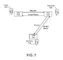
- a third party 702may determine whether the video communication request should be accepted or rejected.
- the third party 702may be a parent or another party responsible for the well-being of one or more recipients 404 associated with an STB 102 b.
- a caller's STB 102 asends a video communication request to a recipient's STB 102 b , where the request is intercepted.
- the STB 102 bmay then identify the caller 402 and the recipient 404 using information within the video communication request.
- the STB 102 bprompts a third party 702 for an indication of acceptance or rejection.
- the third party 702is prompted with the identities of both the caller 402 and the recipient 404 to enable the third party 702 to properly screen the video communication.
- the requestmay include live video captured by the caller's STB 102 a , which may help to identify the caller 402 .
- the third party 702may be always prompted, or never prompted, depending on the third party's preference.
- the STB 102 brejects the request. If, however, the third party 702 indicates acceptance of the request, the STB 102 b may accept the request, subject to acceptance by the recipient 404 . In certain configurations, if the third party 702 does not respond within an established time interval, the STB 102 b may automatically reject the request as though the third party 702 indicated that the request should be rejected.
- the third party 702may be associated with a different STB 102 c than the recipient's STB 102 b .
- the third party's STB 102 c and recipient's STB 102 bmay be located in different rooms of the same house or office, or in completely different geographic areas of the world.
- the third party 702may be prompted using any conventional mechanism. For example, a pop-up window, graphical text overlay, or the like, may be displayed notifying the third party 702 of the request and the identities of the caller 402 and the recipient 404 . Acceptance or rejection of the request may be indicated by pressing a particular button on a remote control 106 , selecting a menu option displayed on a television 104 , or the like.
- third-party screeningmay be combined with any of the screening embodiments using unauthorized/authorized lists 406 , 502 , as described in connection with FIGS. 4-7 .
- a caller 402may be pre-screened using an unauthorized caller list 406 . If the caller 402 is not found within the list 406 , the third party 702 may then be prompted for acceptance or rejection of the request.
- the third party 702may still wish to be notified so that the third party 702 may confer with the caller 402 regarding the attempted communication.
- the third party 702in one embodiment, may establish temporary video communication with the caller 402 to facilitate the screening process.
- the STB 102 bmay be configured to update screening lists 406 , 502 , 602 , 604 , 606 , 608 based on the response (e.g., reject or accept) from the third party 702 .
- a rejection from the third party 702may cause the STB 102 b to add the caller 402 to a general unauthorized caller list 602 or a recipient-specific unauthorized caller list 604 .
- an acceptance responsemay cause the caller 402 to be added to a general authorized caller list 606 or a recipient-specific authorized caller list 608 .
- the screening processneed not be performed at the recipient's STB 102 b .
- a broadcast center 110Internet server, or other intermediate network node may be configured to intercept and screen requests based on the above-described lists 406 , 502 , 602 , 604 , 606 , 608 , which may be stored within, or may be accessible to, the broadcast center 110 .
- all such lists 406 , 502 , 602 , 604 , 606 , 608are specific to the recipient's STB 102 b , allowing the broadcast center 110 to provide screening services for multiple customers.
- a broadcast center 110may be embodied, for example, as a cable head-end or a satellite broadcast center.
- video communication between STBs 102passes through at least one broadcast center 110 , enabling the broadcast center 110 to intercept the request.
- the broadcast center 110may also be configured to prompt a third party 702 at a remote STB 102 c to accept or reject a request. Thus, all of the embodiments disclosed in FIGS. 4-8 may be accomplished within the context of the broadcast center 110 .
- a parent or other responsible partymay be permitted to interact with the broadcast center 110 using a Web browser or other interface to create or update the various lists 406 , 502 , 602 , 604 , 606 , 608 for the recipient's STB 102 b .
- security mechanismssuch as passwords, may be used to limit access to authorized persons.
- the system 1000includes an interception component 1002 , which intercepts a video communications request 1004 as described in connection with FIG. 4 .
- the interception component 1002provides the video communication request 1004 to an identification component 1006 , which identifies the caller 402 (and, in certain embodiments, the recipient 404 ).
- the identification component 1006extracts an identifier 1008 of the caller 402 from the request 1004 .
- the identifier 1008may include, for example, the caller's name, the caller's network address, the network address of the caller's STB 102 a , and the like.
- the extracted identifier 1008is then passed to an authorization component 1012 .
- the authorization component 1012is coupled, in one embodiment, to an unauthorized caller list 406 .
- the unauthorized caller list 406as well as the other screening lists 502 , 602 , 604 , 606 , 608 described above, may be implemented using well known data structures including arrays, linked lists, stacks, queues, databases, etc.
- the authorization component 1012may be further configured to use an identifier (not shown) of the recipient 404 to locate a recipient-specific unauthorized caller list 604 .
- recipient-specific lists 604 , 608are similar to the general lists 406 , 502 , 602 , 606 , except that the list applies to a specific recipient 404 .
- the authorization component 1012searches the list 406 for a match with the extracted caller identifier 1008 . If an exact or sufficiently close match is found, then a reject message is sent to a video communications component 1014 . If a match is not found, then an accept message is sent to a video communications component 1014 . In one configuration, if rejected, the video communication request 1004 and any related meta-data may be stored in a call log 1016 for later review by a recipient 404 , a parent, or other responsible person.
- all video communication requestsmay be recorded in a “message detail record” log (not shown) which can serve multiple purposes, e.g., reconciliation of the billing for usage of the video communications, recording or documenting abusive behavior, allowing the user to select a “calling area” for high frequency of calls to other users in a calling area (similar to telephone billing plans).
- the video communications component 1014prompts the recipient 404 for acceptance of the video communication. If the recipient accepts, the video communications component 1014 establishes two-way video communication between the caller 402 and recipient 404
- the video communications component 1014may terminate the communication process.
- the video communications component 1014may send a message to the STB 102 a notifying the caller 402 of the rejection, including information on re-directing the call to a parent or other authorized person.
- FIG. 11illustrates a system 1100 for screening incoming video communications using a authorized caller list 502 as described above in relation to FIG. 5 .
- a video communication request 1004is processed by an interception component 1002 and an identification component 1006 , after which a caller identifier 1008 is provided to an authorization component 1012 .
- the caller identifier 1008is used to search for a match within an authorized caller list 502 . As in FIG. 5 , if the caller identifier 1008 is found in the authorized caller list 502 , an accept message is sent to the video communication component 1014 . If, however, the caller identifier 1008 is not found in the authorized caller list 502 , a reject message is sent to the video communication component 1014 .
- the accept messagecauses the video communication component 1014 to establish two-way video communication 1102 between the caller's STB 102 a and the recipient's STB 102 b , subject, of course, to acceptance by the recipient 404 .
- the video communication component 1014manages the two-way video communication 1102 from establishment to termination.
- Various systemsare known for providing two-way video communication, such as Microsoft Netmeeting® and CuSeeMe®.
- a video camera 246integrated with the caller's Interactive television system (ITV) 200 a , captures video signals of the caller 402 and transmits them through the network 101 to the recipient's ITV 200 b .
- a microphone 242integrated with the caller's ITV 200 a captures audio signals and transmits them to the recipient's ITV 200 b where speakers 244 (not shown) convert the audio signals to sound waves.
- the recipient's ITV 200 bsends audio and video signals to the caller's ITV 200 a.
- a televisions 104 of the caller 402 and the recipient 404display remote 1104 and local 1106 views in a split-screen arrangement.
- the remote video view 1104includes video images of the caller 402
- the local video view 1106includes video images of the recipient 404 .
- PIPPicture-in-Picture
- multi-sectioned displaysand the like.
- FIG. 12illustrates an exemplary unauthorized caller list 406 and an exemplary authorized caller list 502 according to an embodiment of the invention.
- the unauthorized caller list 406includes a name field 1202 , a reason field 1204 , and an address field 1206 for each caller 402 .
- a name field 1202a name field 1202 , a reason field 1204 , and an address field 1206 for each caller 402 .
- a reason field 1204for each caller 402 .
- address field 1206for each caller 402 .
- more or fewer fieldsmay be provided in other embodiments.
- the address field 1206may include a network address, such as an IP address, of the caller's STB 102 a .
- a network addresssuch as an IP address
- the name field 1202 or the address field 1206is unique for each caller 402 .
- the reason field 1204allows a parent or guardian to identify why the caller 402 was placed on the list 406 . For example, “Brad Smith” was placed on the list because he was “Convicted of a Felony.”
- the reason fieldmay 1204 be automatically generated, for example, in response to a third party 702 accepting or rejecting a request, as described in connection with FIG. 7 .
- the authorized caller list 502may include similar fields 1202 , 1204 , 1206 for each caller 402 .
- the reason field 1204may not relate directly to why the caller 402 is on the list 502 , but, instead, may indicate a relationship between the caller 402 and the recipient 404 .
- “Bert Abrahms”may be a “Relative” of those in a household associated with the recipient's STB 102 b.
- the unauthorized caller list 406 and authorized caller list 502may include as many callers 402 as necessary. Those of relevant skill in the art will recognize that the unauthorized caller list 406 and authorized caller list 502 need not be contained within separate data structures. For example, a single table may be provided, with a field (not shown) for indicating whether an entry corresponds to the unauthorized caller list 406 or the authorized caller list 502 .
- FIG. 13illustrates a table representing a recipient-specific unauthorized caller list 604 .
- the recipient-specific unauthorized caller list 604facilitates screening for a particular recipient 404 .
- the age of son # 1 and other circumstancesmay have lead to a court order forbidding video communication between a father, “Frank Jones” and son # 1 . Accordingly, the father “Frank Jones” is added to the recipient-specific unauthorized caller list 604 for son # 1 .
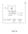
- FIG. 14illustrates a user interface 1400 for prompting a third party 702 to accept or reject a request.
- the promptincludes a caller identifier 1008 and a recipient identifier 1401 .
- the caller identifier 1008may include the name of the caller 402 , “George Burton.”
- the promptmay include a video view 1402 of the caller 402 .
- the video view 1402may include live or recorded video images of the caller 402 .
- the video view 1402allows the third party 702 to get a visual impression of the caller 402 to facilitate the screening process.
- the user interface 1400may include a plurality of buttons 1404 , 1406 , 1408 .
- An accept button 1404provides an accept response to the authorization component 1012 , indicating that the request is accepted, while the reject button 1406 provides a reject response.
- an interview button 1408may allow the third party 702 to establish two-way video communication with the caller 402 prior to authorizing the video communication request.
- a video view 1402may display live video received from the caller's STB 102 a , allowing the third party 702 to see the caller 402 before making a decision whether to accept or reject the request.
- the live videomay be part of the request or may follow the request.
- a third partymay opt to have the STB 102 b reject the request by default.
- FIG. 15illustrates one embodiment of the invention that allows a third party 702 to interview the caller 402 .
- video communication that employs screeningmay be susceptible to “spoofing”, where the caller 402 pretends to be another person.
- the caller 402may configure his STB 102 a to send a false name or address, or to provide a pre-recorded video clip purported to be live video.
- the third party 702can dispel all doubt about the identity of the caller 402 by activating the interview button 1408 and conducting an interview with the caller 402 .
- the interview button 1408causes the video communication component 1014 to establish temporary two-way video communication 1502 between the caller 402 and the third party 702 .
- the third party 702may then question the caller 402 while watching the video view 1402 to verify that the video view 1402 does contain live video. For example, the third party 702 may ask the caller 402 to perform visual acts (e.g., close your eyes) that would not be possible to predict and pre-record.
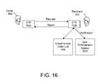
- FIG. 16illustrates yet another embodiment of the invention in which a recipient's STB 102 b is configured to notify a law enforcement agency 1602 in response to receiving one or more requests from a caller 402 on the unauthorized caller list 406 .
- a caller 402may make multiple requests to communicate with a recipient 404 either in an attempt to overload STB 102 b or harass the recipient 404 .
- STB 102 bmaintains a count of the number of failed attempts by the caller 402 , which may be included in a notification to the law enforcement agency 1602 . In some cases, a notification is not sent until the number of failed attempts reaches an established threshold, which may be set by local law.
- the notificationmay be sent via email, instant messaging, fax or other communication medium.
- the notificationincludes the caller identifier 1008 , the number of video communication request attempts made, and details surrounding each video communication request, such as the time and date of the request and the reason for which the caller 402 was added to the list 406 , e.g., court order, known felon, etc.
- the notificationmay include a recipient identifier 1401 and any live video information captured of the caller 402 . Information included in the notification may enable the law enforcement agency 1602 to act to stop video communication requests from the caller 402 to the recipient 404 , and may be useful in enforcing court orders, etc.
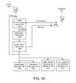
- FIG. 17there is shown a flowchart of a method 1700 for screening incoming video communications in an interactive television system 200 .
- the illustrated method 1700screens incoming calls based on an unauthorized caller list 406 , an authorized caller list 502 , and a third party 702 .
- the inventionneed not use both lists 406 , 502 , or rely on a third party 702 for screening.
- the method 1700begins by intercepting 1702 a video communication request sent from a caller 402 to a recipient 404 . Thereafter, the caller 402 is identified 1704 using information within the video communication request.
- a determination 1706is then made whether the caller 402 is within an unauthorized caller list 406 . If so, the video communication request is rejected 1708 . If not, a determination 1710 is made whether the caller 402 is within an authorized caller list 502 . If so, the video communication request is accepted 1712 , subject to acceptance by the recipient 404 .
- a third party 702is notified 1714 of the caller's identity in one embodiment.
- the third party 702is also prompted 1716 to accept or reject the video communication request.
- a determination 1718is made whether the third party 702 accepted or rejected the video communication request. If the third party 702 accepted the request, then the video communication request is accepted 1712 ; otherwise, the request is rejected 1708 .
- the above-described systems and methodsmay be applied to outgoing, as well as incoming, video communication requests. Just as it is important for parents to screen calls directed to their children, it is also important for parents to screen calls made by their children. People with criminal intentions may attempt to defeat the unauthorized/authorized caller lists 406 , 502 described above by providing children with their video communication addresses (e.g., videophone numbers) and allowing the children to become the callers 402 .
- video communication addressese.g., videophone numbers
- FIG. 18illustrates a system 1800 for screening outgoing video communications according to an embodiment of the present invention.
- the caller's STB 102 amay be configured with an interception component 1802 that intercepts an outgoing video communication request generated by a video communication component 1804 .
- the interception component 1802 and the video communication component 1804may be similar or identical to those described with reference to FIG. 10 .
- the interception component 1804may provide the intercepted request to an authorization component 1806 , which may include or have access to one or more unauthorized recipient lists 1808 , authorized recipient lists 1810 , caller-specific unauthorized recipient lists 1812 , and/or caller-specific authorized recipient lists 1814 .
- These lists 1808 , 1810 , 1812 , 1814are similar or identical to the corresponding lists 602 , 606 , 604 , 608 illustrated in FIG. 6 , except that they are applied to the recipient's identity rather than the caller's identity.
- An identification component(not shown) may be provided to determine the identity of the recipient 404 based on information contained within the request, as previously discussed.
- the authorization component 1806may determine whether the recipient 404 is identified within the unauthorized recipient list 1808 . If the recipient 404 is in the list 1808 , the authorization component 1806 may block the request, e.g., not allow the request to be sent to the recipient's STB 102 b . The authorization component 1806 may notify the caller 402 that the request was blocked due to the recipient 404 being in the list 1808 .
- the authorization component 1806may determine whether the recipient 404 is identified within the authorized recipient list 1810 . In one embodiment, the authorization component 1806 forwards the request to the recipient's STB 102 b for acceptance or rejection only if the recipient 404 is in the list 1810 . Thus, the caller 402 may only contact those recipients 404 who are in the list 1810 .
- a third party 702may also be involved in the screening process.
- the authorization component 1806may send the request to a third party 702 for acceptance or rejection. If the third party 702 accepts the request, the request may be forwarded to the recipient 404 for acceptance or rejection. If the third party 702 rejects the request, the request is blocked, e.g., not forwarded to the recipient 404 .
- the third party 702notifies the authorization component 1806 whether the request was accepted or rejected. Thereafter, if the request was accepted by the third party 702 , the authorization component 1806 forwards the request to the recipient 404 ; otherwise, the authorization component 1806 blocks the request.
- the requestmay include live video of the caller 402 captured by the video camera 246 of FIGS. 2-3 .
- the third party 702may view the live video to determine whether the caller 402 is, in fact, who he or she claims to be. This prevents, for example, a younger child using an older child's identifier to spoof the screening system.
- the third party 702may establish temporary two-way communication with the caller 402 in order, for example, to query the caller 402 regarding the identity of recipient 404 and/or the purpose of the communication. This may allow the caller 402 to ask the third party 702 for permission to contact the recipient 402 where such would not normally be permitted by the unauthorized recipient list 1808 or the authorized recipient list 1810 alone.
- the above-described screening processneed not be performed within the STB 102 a .
- the various components described abovemay operate within an intermediate network node linking the STBs 102 a , 102 of the caller 402 and recipient 404 , respectively.
- the intermediate network nodemay be embodied as a cable head-end, a satellite broadcast center, an Internet server, or the like.
- the authorization component 1806may be configured to use both unauthorized/authorized caller lists 602 , 604 and unauthorized/authorized recipient lists 1802 , 1804 , as well as recipient/caller-specific variations thereof. The same or different lists may be used for incoming and outgoing calls.
- parents or other responsible personsmay block expensive outbound video calls, e.g., the video equivalent of a telephony long distance call, using the above-described techniques. For example, the parent may block all calls that exceed a particular preset rate. Moreover, parents may establish a communication quota based on a set number of minutes per day, a cumulative number minutes per week, or a combination of both. In still other embodiments, parents may tie the above-described limits to a child's spending allowance, which may be redeemed, for example, in video communication minutes, instant messaging minutes, kilobytes of e-mail messages, and the like.
- Incoming/outgoing video communications from/to certain individuals or devicesmay be selectively restricted. Likewise, incoming/outgoing video communications may be limited to those from/to certain individuals or devices. In addition, a parent or other responsible party may selectively screen incoming/outgoing video communications from/to unknown individuals or devices.
Landscapes
- Engineering & Computer Science (AREA)
- Multimedia (AREA)
- Signal Processing (AREA)
- Databases & Information Systems (AREA)
- Business, Economics & Management (AREA)
- General Business, Economics & Management (AREA)
- Computer Networks & Wireless Communication (AREA)
- General Engineering & Computer Science (AREA)
- Power Engineering (AREA)
- Computer Security & Cryptography (AREA)
- Computer Graphics (AREA)
- Telephonic Communication Services (AREA)
Abstract
Description
Claims (25)
Priority Applications (1)
| Application Number | Priority Date | Filing Date | Title |
|---|---|---|---|
| US12/417,408US8237767B2 (en) | 2001-08-22 | 2009-04-02 | System and method for screening video communications within an interactive television system |
Applications Claiming Priority (3)
| Application Number | Priority Date | Filing Date | Title |
|---|---|---|---|
| US09/935,195US7142230B2 (en) | 2001-08-22 | 2001-08-22 | System and method for screening incoming and outgoing video communications within an interactive television system |
| US11/564,188US7518629B2 (en) | 2001-08-22 | 2006-11-28 | System and method for screening video communications within an interactive television system |
| US12/417,408US8237767B2 (en) | 2001-08-22 | 2009-04-02 | System and method for screening video communications within an interactive television system |
Related Parent Applications (1)
| Application Number | Title | Priority Date | Filing Date |
|---|---|---|---|
| US11/564,188ContinuationUS7518629B2 (en) | 2001-08-22 | 2006-11-28 | System and method for screening video communications within an interactive television system |
Publications (2)
| Publication Number | Publication Date |
|---|---|
| US20090199228A1 US20090199228A1 (en) | 2009-08-06 |
| US8237767B2true US8237767B2 (en) | 2012-08-07 |
Family
ID=25466691
Family Applications (3)
| Application Number | Title | Priority Date | Filing Date |
|---|---|---|---|
| US09/935,195Expired - LifetimeUS7142230B2 (en) | 2001-08-22 | 2001-08-22 | System and method for screening incoming and outgoing video communications within an interactive television system |
| US11/564,188Expired - LifetimeUS7518629B2 (en) | 2001-08-22 | 2006-11-28 | System and method for screening video communications within an interactive television system |
| US12/417,408Expired - Fee RelatedUS8237767B2 (en) | 2001-08-22 | 2009-04-02 | System and method for screening video communications within an interactive television system |
Family Applications Before (2)
| Application Number | Title | Priority Date | Filing Date |
|---|---|---|---|
| US09/935,195Expired - LifetimeUS7142230B2 (en) | 2001-08-22 | 2001-08-22 | System and method for screening incoming and outgoing video communications within an interactive television system |
| US11/564,188Expired - LifetimeUS7518629B2 (en) | 2001-08-22 | 2006-11-28 | System and method for screening video communications within an interactive television system |
Country Status (2)
| Country | Link |
|---|---|
| US (3) | US7142230B2 (en) |
| WO (1) | WO2003019941A1 (en) |
Families Citing this family (70)
| Publication number | Priority date | Publication date | Assignee | Title |
|---|---|---|---|---|
| US7899167B1 (en)* | 2003-08-15 | 2011-03-01 | Securus Technologies, Inc. | Centralized call processing |
| US7142230B2 (en)* | 2001-08-22 | 2006-11-28 | Digeo, Inc. | System and method for screening incoming and outgoing video communications within an interactive television system |
| US7916845B2 (en)* | 2006-04-13 | 2011-03-29 | Securus Technologies, Inc. | Unauthorized call activity detection and prevention systems and methods for a Voice over Internet Protocol environment |
| US7730510B1 (en)* | 2002-09-19 | 2010-06-01 | Microsoft Corporation | Methods and systems for conditionally managing entertainment systems |
| US7529357B1 (en)* | 2003-08-15 | 2009-05-05 | Evercom Systems, Inc. | Inmate management and call processing systems and methods |
| US8320528B2 (en) | 2004-06-14 | 2012-11-27 | At&T Intellectual Property I, L.P. | System and method for electronic message notification |
| US9779750B2 (en)* | 2004-07-30 | 2017-10-03 | Invention Science Fund I, Llc | Cue-aware privacy filter for participants in persistent communications |
| JP4592551B2 (en)* | 2004-11-10 | 2010-12-01 | シャープ株式会社 | Communication device |
| US8107600B1 (en) | 2005-02-07 | 2012-01-31 | O'keeffe Sean P | High volume call advertising system and method |
| HU0500314D0 (en)* | 2005-03-18 | 2005-05-30 | Fon Telekommunikacios Kft B V | Method and device for achieving and checking telephone calls, in particular to penitentiaries, prisons |
| US20060230421A1 (en)* | 2005-03-30 | 2006-10-12 | Sbc Knowledge Ventures, Lp | Method of using an entertainment system and an apparatus and handset for use with the entertainment system |
| DE102005016510A1 (en)* | 2005-04-08 | 2006-10-12 | Buderus Schleiftechnik Gmbh | Device for machining hardened workpieces |
| US7907164B2 (en)* | 2005-05-02 | 2011-03-15 | Lifesize Communications, Inc. | Integrated videoconferencing system |
| US20070165106A1 (en)* | 2005-05-02 | 2007-07-19 | Groves Randall D | Distributed Videoconferencing Processing |
| TW200743385A (en)* | 2006-05-05 | 2007-11-16 | Amtran Technology Co Ltd | Method of audio-visual communication using television and television using the same |
| US20070033256A1 (en)* | 2005-07-12 | 2007-02-08 | Yuval Ben-Itzhak | System and method for the prevention of unsolicited calls and contacts |
| US7688976B2 (en)* | 2005-07-14 | 2010-03-30 | Tara Chand Singhal | Random wave envelope derived random numbers and their use in generating transient keys in communication security application part I |
| JP4933156B2 (en)* | 2005-07-29 | 2012-05-16 | 株式会社リコー | Image shooting device |
| KR100725057B1 (en)* | 2005-11-03 | 2007-06-08 | 삼성전자주식회사 | Video call device and method in portable wireless terminal |
| KR20080077991A (en)* | 2005-12-19 | 2008-08-26 | 마쯔시다덴기산교 가부시키가이샤 | Content management system |
| TWM295862U (en)* | 2005-12-23 | 2006-08-11 | Universal Scient Ind Co Ltd | The remote control system and the remote controller of a network telephone communication system |
| US8341238B2 (en) | 2006-03-03 | 2012-12-25 | Sharp Laboratories Of America, Inc. | Methods and systems for multiple-device session synchronization |
| US8069461B2 (en) | 2006-03-30 | 2011-11-29 | Verizon Services Corp. | On-screen program guide with interactive programming recommendations |
| US20070243916A1 (en)* | 2006-04-14 | 2007-10-18 | Lee Ren E | Objective oriented reality horror survival game |
| US20080024593A1 (en)* | 2006-07-25 | 2008-01-31 | Larisa Tsirinsky | Multimedia Communication System |
| US8418217B2 (en) | 2006-09-06 | 2013-04-09 | Verizon Patent And Licensing Inc. | Systems and methods for accessing media content |
| US8739240B2 (en) | 2006-09-12 | 2014-05-27 | At&T Intellectual Property I, L.P. | Authoring system for IPTV network |
| US8566874B2 (en) | 2006-10-03 | 2013-10-22 | Verizon Patent And Licensing Inc. | Control tools for media content access systems and methods |
| US8464295B2 (en) | 2006-10-03 | 2013-06-11 | Verizon Patent And Licensing Inc. | Interactive search graphical user interface systems and methods |
| US20080141294A1 (en)* | 2006-12-12 | 2008-06-12 | General Instrument Corporation | Method and System for Managing Access to a Video Communication Device |
| US8068825B2 (en) | 2006-12-13 | 2011-11-29 | Cingular Wireless Ii, Llc | Second party control over mobile device usage |
| US8190754B2 (en)* | 2006-12-14 | 2012-05-29 | Verizon Patent And Licensing Inc. | Parental controls in a media network |
| US8510780B2 (en) | 2006-12-21 | 2013-08-13 | Verizon Patent And Licensing Inc. | Program guide navigation tools for media content access systems and methods |
| US8015581B2 (en) | 2007-01-05 | 2011-09-06 | Verizon Patent And Licensing Inc. | Resource data configuration for media content access systems and methods |
| US9137490B2 (en)* | 2007-04-10 | 2015-09-15 | At&T Intellectual Property I, L.P. | System and method for video transmission scheduling |
| US8103965B2 (en) | 2007-06-28 | 2012-01-24 | Verizon Patent And Licensing Inc. | Media content recording and healing statuses |
| US9003464B2 (en) | 2007-08-27 | 2015-04-07 | At&T Intellectual Property I, L.P. | System and method of verifying a video blackout event |
| US8330789B2 (en)* | 2007-10-31 | 2012-12-11 | At&T Intellectual Property I, L.P. | Integrated devices for multimedia content delivery and video conferencing |
| US8924997B2 (en) | 2007-11-01 | 2014-12-30 | At&T Intellectual Property, I, L.P. | System and method of restricting access to media content |
| JP5145914B2 (en)* | 2007-12-14 | 2013-02-20 | ソニー株式会社 | Content viewing management apparatus, content viewing management method, program, and content viewing management system |
| US8051447B2 (en) | 2007-12-19 | 2011-11-01 | Verizon Patent And Licensing Inc. | Condensed program guide for media content access systems and methods |
| US20090182806A1 (en)* | 2008-01-15 | 2009-07-16 | Vishnu-Kumar Shivaji-Rao | Methods and Systems for Content-Consumption-Aware Device Communication |
| US20090182805A1 (en)* | 2008-01-15 | 2009-07-16 | Vishnu-Kumar Shivaji-Rao | Methods and Systems for Peripheral-Device-Assisted Networking |
| US8156547B2 (en)* | 2008-01-15 | 2012-04-10 | Sharp Laboratories Of America, Inc. | Methods and systems for device-independent portable session synchronization |
| US8001236B2 (en)* | 2008-03-13 | 2011-08-16 | Sharp Laboratories Of America, Inc. | Methods and systems for content-consumption device monitoring and control |
| US20090234955A1 (en)* | 2008-03-13 | 2009-09-17 | Mark Gregory Hanley | Methods and Systems for Synchronization of Multiple Applications |
| US20100083338A1 (en)* | 2008-10-01 | 2010-04-01 | I-Jen Chiang | Remote control device and remote control system |
| US8352997B2 (en) | 2008-11-14 | 2013-01-08 | At&T Intellectual Property I, L.P. | System and method of monitoring blackout events |
| US8271650B2 (en)* | 2009-08-25 | 2012-09-18 | Vizibility Inc. | Systems and method of identifying and managing abusive requests |
| US9756292B2 (en)* | 2010-04-05 | 2017-09-05 | Alcatel Lucent | System and method for distributing digital video streams from remote video surveillance cameras to display devices |
| CN105791776B (en)* | 2010-10-16 | 2018-12-11 | 佳能株式会社 | The sending method of server apparatus and video data |
| JP2012138772A (en)* | 2010-12-27 | 2012-07-19 | Toshiba Corp | Apparatus information communication method, image display device, and image display system |
| US8832284B1 (en) | 2011-06-16 | 2014-09-09 | Google Inc. | Virtual socializing |
| US8917306B2 (en)* | 2011-07-29 | 2014-12-23 | Cisco Technology, Inc. | Previewing video data in a video communication environment |
| US9148406B2 (en)* | 2012-04-26 | 2015-09-29 | Dell Products L.P. | Protected media stream source |
| US9025746B2 (en)* | 2012-07-03 | 2015-05-05 | Avaya Inc. | System and method for visual caller identification |
| US8948361B2 (en)* | 2012-07-03 | 2015-02-03 | Avaya Inc. | Mitigating spam and identifying callers in video calls |
| US9118654B2 (en) | 2013-10-11 | 2015-08-25 | Edifire LLC | Methods and systems for compliance monitoring in secure media-based conferencing |
| US8970660B1 (en) | 2013-10-11 | 2015-03-03 | Edifire LLC | Methods and systems for authentication in secure media-based conferencing |
| US9118809B2 (en) | 2013-10-11 | 2015-08-25 | Edifire LLC | Methods and systems for multi-factor authentication in secure media-based conferencing |
| US9253439B2 (en)* | 2014-02-24 | 2016-02-02 | Cellco Partnership | Managing complex video call scenarios in volte calls |
| US9137187B1 (en) | 2014-09-29 | 2015-09-15 | Edifire LLC | Dynamic conference session state management in secure media-based conferencing |
| US9131112B1 (en) | 2014-09-29 | 2015-09-08 | Edifire LLC | Dynamic signaling and resource allocation in secure media-based conferencing |
| US9282130B1 (en) | 2014-09-29 | 2016-03-08 | Edifire LLC | Dynamic media negotiation in secure media-based conferencing |
| US9167098B1 (en) | 2014-09-29 | 2015-10-20 | Edifire LLC | Dynamic conference session re-routing in secure media-based conferencing |
| US10963937B1 (en)* | 2017-07-18 | 2021-03-30 | Wells Fargo Bank, N.A. | Online ecommerce in augmented reality platforms |
| US10630937B1 (en) | 2018-12-19 | 2020-04-21 | Motorola Solutions, Inc. | Device, system and method for transmitting one or more of annotations and video prior to a video call |
| US11509862B2 (en)* | 2020-08-07 | 2022-11-22 | Arris Enterprises Llc | Multi-modal approach to a secure and closed solution monitoring and control of user data |
| CA3193236A1 (en) | 2020-08-07 | 2022-02-10 | Navneeth N. Kannan | Multi-modal approach to a secure and closed solution monitoring and control of user data |
| TR202021626A2 (en)* | 2020-12-24 | 2021-04-21 | Turkcell Technology Research And Development Co | A SYSTEM THAT ENABLES TELEVISIONS TO PERFORM VIDEO COMMUNICATION |
Citations (3)
| Publication number | Priority date | Publication date | Assignee | Title |
|---|---|---|---|---|
| US5754641A (en)* | 1995-11-30 | 1998-05-19 | Bell Atlantic Network Services, Inc. | Method of screening outgoing calls via a video display |
| US6246756B1 (en)* | 1999-03-17 | 2001-06-12 | Advanced Micro Devices, Inc. | Method and system to meter and control usage of telephone systems |
| US7142230B2 (en)* | 2001-08-22 | 2006-11-28 | Digeo, Inc. | System and method for screening incoming and outgoing video communications within an interactive television system |
Family Cites Families (13)
| Publication number | Priority date | Publication date | Assignee | Title |
|---|---|---|---|---|
| US5559868A (en)* | 1993-08-30 | 1996-09-24 | Lucent Technologies Inc. | Method for sending and receiving video images |
| US5473671A (en)* | 1994-03-11 | 1995-12-05 | At&T Corp. | Selective screening of incoming calls for cellular telephone systems |
| USH1714H (en)* | 1995-05-03 | 1998-03-03 | Lucent Technologies Inc. | Automatic still image transmission upon call connection |
| US5974133A (en)* | 1996-04-30 | 1999-10-26 | Southwestern Bell Technology Resources, Inc. | Method and apparatus for facilitating communication across multiple locations |
| US6219793B1 (en)* | 1996-09-11 | 2001-04-17 | Hush, Inc. | Method of using fingerprints to authenticate wireless communications |
| US6141058A (en)* | 1996-12-16 | 2000-10-31 | Thomson Licensing S.A. | Television receiver having a user-editable telephone system caller-ID feature |
| US5907604A (en) | 1997-03-25 | 1999-05-25 | Sony Corporation | Image icon associated with caller ID |
| US5999207A (en)* | 1997-05-16 | 1999-12-07 | Scientific-Atlanta, Inc. | Method and apparatus for implementing a user interface for a videophone in a cable television network |
| US5995603A (en)* | 1997-05-23 | 1999-11-30 | At&T Corp | Telephone call screening device |
| US6463276B1 (en)* | 1997-12-05 | 2002-10-08 | Telefonaktiebolaget L M Ericsson (Publ) | Mobile terminal having conditional blocking of outgoing call requests |
| US6259779B1 (en)* | 1998-08-27 | 2001-07-10 | Michael O. Council | Method and apparatus for generating and/or updating an authorization list associated with a telephone subscriber |
| US6744868B2 (en) | 2001-05-31 | 2004-06-01 | Alcatel | Call party profile presentation service in a multimedia-capable network |
| US7006613B2 (en)* | 2001-07-27 | 2006-02-28 | Digeo, Inc. | System and method for screening incoming video communications within an interactive television system |
- 2001
- 2001-08-22USUS09/935,195patent/US7142230B2/ennot_activeExpired - Lifetime
- 2002
- 2002-06-20WOPCT/US2002/019553patent/WO2003019941A1/ennot_activeApplication Discontinuation
- 2006
- 2006-11-28USUS11/564,188patent/US7518629B2/ennot_activeExpired - Lifetime
- 2009
- 2009-04-02USUS12/417,408patent/US8237767B2/ennot_activeExpired - Fee Related
Patent Citations (4)
| Publication number | Priority date | Publication date | Assignee | Title |
|---|---|---|---|---|
| US5754641A (en)* | 1995-11-30 | 1998-05-19 | Bell Atlantic Network Services, Inc. | Method of screening outgoing calls via a video display |
| US6246756B1 (en)* | 1999-03-17 | 2001-06-12 | Advanced Micro Devices, Inc. | Method and system to meter and control usage of telephone systems |
| US7142230B2 (en)* | 2001-08-22 | 2006-11-28 | Digeo, Inc. | System and method for screening incoming and outgoing video communications within an interactive television system |
| US7518629B2 (en)* | 2001-08-22 | 2009-04-14 | Vulcan Ventures, Inc. | System and method for screening video communications within an interactive television system |
Also Published As
| Publication number | Publication date |
|---|---|
| US7142230B2 (en) | 2006-11-28 |
| US7518629B2 (en) | 2009-04-14 |
| US20070124760A1 (en) | 2007-05-31 |
| US20090199228A1 (en) | 2009-08-06 |
| WO2003019941A1 (en) | 2003-03-06 |
| US20030041326A1 (en) | 2003-02-27 |
Similar Documents
| Publication | Publication Date | Title |
|---|---|---|
| US8237767B2 (en) | System and method for screening video communications within an interactive television system | |
| US7006613B2 (en) | System and method for screening incoming video communications within an interactive television system | |
| US20030041333A1 (en) | System and method for automatically answering and recording video calls | |
| US20030041332A1 (en) | System and method for mitigating interruptions during television viewing | |
| US9819989B2 (en) | Remote control device signal distribution | |
| US7788692B2 (en) | System and method for simultaneously displaying video programming and instant messaging | |
| US7243123B1 (en) | Video call routing with presence determination | |
| US10108804B2 (en) | Electronic permission slips for controlling access to multimedia content | |
| US9621943B2 (en) | Multimedia processing resource with interactive voice response | |
| US20020054206A1 (en) | Systems and devices for audio and video capture and communication during television broadcasts | |
| US20030005462A1 (en) | Noise reduction for teleconferencing within an interactive television system | |
| US20050039214A1 (en) | System and method for providing direct, context-sensitive customer support in an interactive television system | |
| US20040244056A1 (en) | System and method for providing direct, context-sensitive customer support in an interactive television system | |
| US8555312B2 (en) | Multimedia channel sharing | |
| US8881192B2 (en) | Television content through supplementary media channels | |
| US20030046705A1 (en) | System and method for enabling communication between video-enabled and non-video-enabled communication devices | |
| US20100037256A1 (en) | Multimedia Channel Sharing Across Access Network Boundaries | |
| US20100161801A1 (en) | Multimedia processing resource with distributed settings | |
| US20030041331A1 (en) | System and method for mitigating interruptions during television viewing | |
| WO2003019945A1 (en) | System and method for mitigating interruptions during television viewing | |
| US9043852B2 (en) | Methods, devices, and computer program products for providing instant messaging in conjunction with an audiovisual, video, or audio program | |
| KR20100069380A (en) | Iptv settop box remote control equipped with contents display unit and iptv settop box | |
| US20120017242A1 (en) | Long Distance Audio Attendance | |
| WO2003021960A1 (en) | Tv system with group communication | |
| WO2002069640A1 (en) | System and method for providing direct, context-sensitive customer support in an interactive television system |
Legal Events
| Date | Code | Title | Description |
|---|---|---|---|
| AS | Assignment | Owner name:VULCAN VENTURES, INC., WASHINGTON Free format text:ASSIGNMENT OF ASSIGNORS INTEREST;ASSIGNORS:NOVAK, ROBERT E.;BILLMAIER, JAMES A.;ISTVAN, ANTHONY F.;REEL/FRAME:022967/0021 Effective date:20011011 | |
| AS | Assignment | Owner name:ARRIS GROUP, INC., GEORGIA Free format text:ASSIGNMENT OF ASSIGNORS INTEREST;ASSIGNOR:DIGEO, INC AND VULCAN VENTURES, INC.;REEL/FRAME:026621/0258 Effective date:20090922 | |
| ZAAA | Notice of allowance and fees due | Free format text:ORIGINAL CODE: NOA | |
| ZAAB | Notice of allowance mailed | Free format text:ORIGINAL CODE: MN/=. | |
| STCF | Information on status: patent grant | Free format text:PATENTED CASE | |
| AS | Assignment | Owner name:ARRIS ENTERPRISES, INC., GEORGIA Free format text:MERGER;ASSIGNOR:ARRIS GROUP, INC.;REEL/FRAME:030228/0349 Effective date:20130416 | |
| AS | Assignment | Owner name:BANK OF AMERICA, N.A., AS ADMINISTRATIVE AGENT, IL Free format text:SECURITY AGREEMENT;ASSIGNORS:ARRIS GROUP, INC.;ARRIS ENTERPRISES, INC.;ARRIS SOLUTIONS, INC.;AND OTHERS;REEL/FRAME:030498/0023 Effective date:20130417 Owner name:BANK OF AMERICA, N.A., AS ADMINISTRATIVE AGENT, ILLINOIS Free format text:SECURITY AGREEMENT;ASSIGNORS:ARRIS GROUP, INC.;ARRIS ENTERPRISES, INC.;ARRIS SOLUTIONS, INC.;AND OTHERS;REEL/FRAME:030498/0023 Effective date:20130417 | |
| FPAY | Fee payment | Year of fee payment:4 | |
| AS | Assignment | Owner name:ARRIS ENTERPRISES LLC, PENNSYLVANIA Free format text:CHANGE OF NAME;ASSIGNOR:ARRIS ENTERPRISES INC;REEL/FRAME:041995/0031 Effective date:20151231 | |
| AS | Assignment | Owner name:GENERAL INSTRUMENT INTERNATIONAL HOLDINGS, INC., P Free format text:TERMINATION AND RELEASE OF SECURITY INTEREST IN PATENTS;ASSIGNOR:BANK OF AMERICA, N.A., AS ADMINISTRATIVE AGENT;REEL/FRAME:048825/0294 Effective date:20190404 Owner name:AEROCAST, INC., PENNSYLVANIA Free format text:TERMINATION AND RELEASE OF SECURITY INTEREST IN PATENTS;ASSIGNOR:BANK OF AMERICA, N.A., AS ADMINISTRATIVE AGENT;REEL/FRAME:048825/0294 Effective date:20190404 Owner name:ARRIS ENTERPRISES, INC., PENNSYLVANIA Free format text:TERMINATION AND RELEASE OF SECURITY INTEREST IN PATENTS;ASSIGNOR:BANK OF AMERICA, N.A., AS ADMINISTRATIVE AGENT;REEL/FRAME:048825/0294 Effective date:20190404 Owner name:NEXTLEVEL SYSTEMS (PUERTO RICO), INC., PENNSYLVANI Free format text:TERMINATION AND RELEASE OF SECURITY INTEREST IN PATENTS;ASSIGNOR:BANK OF AMERICA, N.A., AS ADMINISTRATIVE AGENT;REEL/FRAME:048825/0294 Effective date:20190404 Owner name:NETOPIA, INC., PENNSYLVANIA Free format text:TERMINATION AND RELEASE OF SECURITY INTEREST IN PATENTS;ASSIGNOR:BANK OF AMERICA, N.A., AS ADMINISTRATIVE AGENT;REEL/FRAME:048825/0294 Effective date:20190404 Owner name:ARRIS HOLDINGS CORP. OF ILLINOIS, INC., PENNSYLVAN Free format text:TERMINATION AND RELEASE OF SECURITY INTEREST IN PATENTS;ASSIGNOR:BANK OF AMERICA, N.A., AS ADMINISTRATIVE AGENT;REEL/FRAME:048825/0294 Effective date:20190404 Owner name:POWER GUARD, INC., PENNSYLVANIA Free format text:TERMINATION AND RELEASE OF SECURITY INTEREST IN PATENTS;ASSIGNOR:BANK OF AMERICA, N.A., AS ADMINISTRATIVE AGENT;REEL/FRAME:048825/0294 Effective date:20190404 Owner name:ARRIS KOREA, INC., PENNSYLVANIA Free format text:TERMINATION AND RELEASE OF SECURITY INTEREST IN PATENTS;ASSIGNOR:BANK OF AMERICA, N.A., AS ADMINISTRATIVE AGENT;REEL/FRAME:048825/0294 Effective date:20190404 Owner name:TEXSCAN CORPORATION, PENNSYLVANIA Free format text:TERMINATION AND RELEASE OF SECURITY INTEREST IN PATENTS;ASSIGNOR:BANK OF AMERICA, N.A., AS ADMINISTRATIVE AGENT;REEL/FRAME:048825/0294 Effective date:20190404 Owner name:LEAPSTONE SYSTEMS, INC., PENNSYLVANIA Free format text:TERMINATION AND RELEASE OF SECURITY INTEREST IN PATENTS;ASSIGNOR:BANK OF AMERICA, N.A., AS ADMINISTRATIVE AGENT;REEL/FRAME:048825/0294 Effective date:20190404 Owner name:ARRIS GROUP, INC., PENNSYLVANIA Free format text:TERMINATION AND RELEASE OF SECURITY INTEREST IN PATENTS;ASSIGNOR:BANK OF AMERICA, N.A., AS ADMINISTRATIVE AGENT;REEL/FRAME:048825/0294 Effective date:20190404 Owner name:IMEDIA CORPORATION, PENNSYLVANIA Free format text:TERMINATION AND RELEASE OF SECURITY INTEREST IN PATENTS;ASSIGNOR:BANK OF AMERICA, N.A., AS ADMINISTRATIVE AGENT;REEL/FRAME:048825/0294 Effective date:20190404 Owner name:QUANTUM BRIDGE COMMUNICATIONS, INC., PENNSYLVANIA Free format text:TERMINATION AND RELEASE OF SECURITY INTEREST IN PATENTS;ASSIGNOR:BANK OF AMERICA, N.A., AS ADMINISTRATIVE AGENT;REEL/FRAME:048825/0294 Effective date:20190404 Owner name:GIC INTERNATIONAL HOLDCO LLC, PENNSYLVANIA Free format text:TERMINATION AND RELEASE OF SECURITY INTEREST IN PATENTS;ASSIGNOR:BANK OF AMERICA, N.A., AS ADMINISTRATIVE AGENT;REEL/FRAME:048825/0294 Effective date:20190404 Owner name:GENERAL INSTRUMENT AUTHORIZATION SERVICES, INC., P Free format text:TERMINATION AND RELEASE OF SECURITY INTEREST IN PATENTS;ASSIGNOR:BANK OF AMERICA, N.A., AS ADMINISTRATIVE AGENT;REEL/FRAME:048825/0294 Effective date:20190404 Owner name:GENERAL INSTRUMENT CORPORATION, PENNSYLVANIA Free format text:TERMINATION AND RELEASE OF SECURITY INTEREST IN PATENTS;ASSIGNOR:BANK OF AMERICA, N.A., AS ADMINISTRATIVE AGENT;REEL/FRAME:048825/0294 Effective date:20190404 Owner name:BROADBUS TECHNOLOGIES, INC., PENNSYLVANIA Free format text:TERMINATION AND RELEASE OF SECURITY INTEREST IN PATENTS;ASSIGNOR:BANK OF AMERICA, N.A., AS ADMINISTRATIVE AGENT;REEL/FRAME:048825/0294 Effective date:20190404 Owner name:BIG BAND NETWORKS, INC., PENNSYLVANIA Free format text:TERMINATION AND RELEASE OF SECURITY INTEREST IN PATENTS;ASSIGNOR:BANK OF AMERICA, N.A., AS ADMINISTRATIVE AGENT;REEL/FRAME:048825/0294 Effective date:20190404 Owner name:CCE SOFTWARE LLC, PENNSYLVANIA Free format text:TERMINATION AND RELEASE OF SECURITY INTEREST IN PATENTS;ASSIGNOR:BANK OF AMERICA, N.A., AS ADMINISTRATIVE AGENT;REEL/FRAME:048825/0294 Effective date:20190404 Owner name:4HOME, INC., PENNSYLVANIA Free format text:TERMINATION AND RELEASE OF SECURITY INTEREST IN PATENTS;ASSIGNOR:BANK OF AMERICA, N.A., AS ADMINISTRATIVE AGENT;REEL/FRAME:048825/0294 Effective date:20190404 Owner name:MOTOROLA WIRELINE NETWORKS, INC., PENNSYLVANIA Free format text:TERMINATION AND RELEASE OF SECURITY INTEREST IN PATENTS;ASSIGNOR:BANK OF AMERICA, N.A., AS ADMINISTRATIVE AGENT;REEL/FRAME:048825/0294 Effective date:20190404 Owner name:SUNUP DESIGN SYSTEMS, INC., PENNSYLVANIA Free format text:TERMINATION AND RELEASE OF SECURITY INTEREST IN PATENTS;ASSIGNOR:BANK OF AMERICA, N.A., AS ADMINISTRATIVE AGENT;REEL/FRAME:048825/0294 Effective date:20190404 Owner name:JERROLD DC RADIO, INC., PENNSYLVANIA Free format text:TERMINATION AND RELEASE OF SECURITY INTEREST IN PATENTS;ASSIGNOR:BANK OF AMERICA, N.A., AS ADMINISTRATIVE AGENT;REEL/FRAME:048825/0294 Effective date:20190404 Owner name:THE GI REALTY TRUST 1996, PENNSYLVANIA Free format text:TERMINATION AND RELEASE OF SECURITY INTEREST IN PATENTS;ASSIGNOR:BANK OF AMERICA, N.A., AS ADMINISTRATIVE AGENT;REEL/FRAME:048825/0294 Effective date:20190404 Owner name:UCENTRIC SYSTEMS, INC., PENNSYLVANIA Free format text:TERMINATION AND RELEASE OF SECURITY INTEREST IN PATENTS;ASSIGNOR:BANK OF AMERICA, N.A., AS ADMINISTRATIVE AGENT;REEL/FRAME:048825/0294 Effective date:20190404 Owner name:ARRIS SOLUTIONS, INC., PENNSYLVANIA Free format text:TERMINATION AND RELEASE OF SECURITY INTEREST IN PATENTS;ASSIGNOR:BANK OF AMERICA, N.A., AS ADMINISTRATIVE AGENT;REEL/FRAME:048825/0294 Effective date:20190404 Owner name:GIC INTERNATIONAL CAPITAL LLC, PENNSYLVANIA Free format text:TERMINATION AND RELEASE OF SECURITY INTEREST IN PATENTS;ASSIGNOR:BANK OF AMERICA, N.A., AS ADMINISTRATIVE AGENT;REEL/FRAME:048825/0294 Effective date:20190404 Owner name:SETJAM, INC., PENNSYLVANIA Free format text:TERMINATION AND RELEASE OF SECURITY INTEREST IN PATENTS;ASSIGNOR:BANK OF AMERICA, N.A., AS ADMINISTRATIVE AGENT;REEL/FRAME:048825/0294 Effective date:20190404 Owner name:ACADIA AIC, INC., PENNSYLVANIA Free format text:TERMINATION AND RELEASE OF SECURITY INTEREST IN PATENTS;ASSIGNOR:BANK OF AMERICA, N.A., AS ADMINISTRATIVE AGENT;REEL/FRAME:048825/0294 Effective date:20190404 Owner name:MODULUS VIDEO, INC., PENNSYLVANIA Free format text:TERMINATION AND RELEASE OF SECURITY INTEREST IN PATENTS;ASSIGNOR:BANK OF AMERICA, N.A., AS ADMINISTRATIVE AGENT;REEL/FRAME:048825/0294 Effective date:20190404 Owner name:ARRIS HOLDINGS CORP. OF ILLINOIS, INC., PENNSYLVANIA Free format text:TERMINATION AND RELEASE OF SECURITY INTEREST IN PATENTS;ASSIGNOR:BANK OF AMERICA, N.A., AS ADMINISTRATIVE AGENT;REEL/FRAME:048825/0294 Effective date:20190404 Owner name:NEXTLEVEL SYSTEMS (PUERTO RICO), INC., PENNSYLVANIA Free format text:TERMINATION AND RELEASE OF SECURITY INTEREST IN PATENTS;ASSIGNOR:BANK OF AMERICA, N.A., AS ADMINISTRATIVE AGENT;REEL/FRAME:048825/0294 Effective date:20190404 Owner name:GENERAL INSTRUMENT INTERNATIONAL HOLDINGS, INC., PENNSYLVANIA Free format text:TERMINATION AND RELEASE OF SECURITY INTEREST IN PATENTS;ASSIGNOR:BANK OF AMERICA, N.A., AS ADMINISTRATIVE AGENT;REEL/FRAME:048825/0294 Effective date:20190404 Owner name:GENERAL INSTRUMENT AUTHORIZATION SERVICES, INC., PENNSYLVANIA Free format text:TERMINATION AND RELEASE OF SECURITY INTEREST IN PATENTS;ASSIGNOR:BANK OF AMERICA, N.A., AS ADMINISTRATIVE AGENT;REEL/FRAME:048825/0294 Effective date:20190404 | |
| AS | Assignment | Owner name:ARRIS ENTERPRISES LLC, GEORGIA Free format text:CHANGE OF NAME;ASSIGNOR:ARRIS ENTERPRISES, INC.;REEL/FRAME:049586/0470 Effective date:20151231 | |
| AS | Assignment | Owner name:WILMINGTON TRUST, NATIONAL ASSOCIATION, AS COLLATE Free format text:PATENT SECURITY AGREEMENT;ASSIGNOR:ARRIS ENTERPRISES LLC;REEL/FRAME:049820/0495 Effective date:20190404 Owner name:JPMORGAN CHASE BANK, N.A., NEW YORK Free format text:ABL SECURITY AGREEMENT;ASSIGNORS:COMMSCOPE, INC. OF NORTH CAROLINA;COMMSCOPE TECHNOLOGIES LLC;ARRIS ENTERPRISES LLC;AND OTHERS;REEL/FRAME:049892/0396 Effective date:20190404 Owner name:JPMORGAN CHASE BANK, N.A., NEW YORK Free format text:TERM LOAN SECURITY AGREEMENT;ASSIGNORS:COMMSCOPE, INC. OF NORTH CAROLINA;COMMSCOPE TECHNOLOGIES LLC;ARRIS ENTERPRISES LLC;AND OTHERS;REEL/FRAME:049905/0504 Effective date:20190404 Owner name:WILMINGTON TRUST, NATIONAL ASSOCIATION, AS COLLATERAL AGENT, CONNECTICUT Free format text:PATENT SECURITY AGREEMENT;ASSIGNOR:ARRIS ENTERPRISES LLC;REEL/FRAME:049820/0495 Effective date:20190404 | |
| MAFP | Maintenance fee payment | Free format text:PAYMENT OF MAINTENANCE FEE, 8TH YEAR, LARGE ENTITY (ORIGINAL EVENT CODE: M1552); ENTITY STATUS OF PATENT OWNER: LARGE ENTITY Year of fee payment:8 | |
| AS | Assignment | Owner name:WILMINGTON TRUST, DELAWARE Free format text:SECURITY INTEREST;ASSIGNORS:ARRIS SOLUTIONS, INC.;ARRIS ENTERPRISES LLC;COMMSCOPE TECHNOLOGIES LLC;AND OTHERS;REEL/FRAME:060752/0001 Effective date:20211115 | |
| FEPP | Fee payment procedure | Free format text:MAINTENANCE FEE REMINDER MAILED (ORIGINAL EVENT CODE: REM.); ENTITY STATUS OF PATENT OWNER: LARGE ENTITY | |
| LAPS | Lapse for failure to pay maintenance fees | Free format text:PATENT EXPIRED FOR FAILURE TO PAY MAINTENANCE FEES (ORIGINAL EVENT CODE: EXP.); ENTITY STATUS OF PATENT OWNER: LARGE ENTITY | |
| STCH | Information on status: patent discontinuation | Free format text:PATENT EXPIRED DUE TO NONPAYMENT OF MAINTENANCE FEES UNDER 37 CFR 1.362 | |
| FP | Lapsed due to failure to pay maintenance fee | Effective date:20240807 | |
| AS | Assignment | Owner name:RUCKUS WIRELESS, LLC (F/K/A RUCKUS WIRELESS, INC.), NORTH CAROLINA Free format text:RELEASE OF SECURITY INTEREST AT REEL/FRAME 049905/0504;ASSIGNOR:JPMORGAN CHASE BANK, N.A., AS COLLATERAL AGENT;REEL/FRAME:071477/0255 Effective date:20241217 Owner name:COMMSCOPE TECHNOLOGIES LLC, NORTH CAROLINA Free format text:RELEASE OF SECURITY INTEREST AT REEL/FRAME 049905/0504;ASSIGNOR:JPMORGAN CHASE BANK, N.A., AS COLLATERAL AGENT;REEL/FRAME:071477/0255 Effective date:20241217 Owner name:COMMSCOPE, INC. OF NORTH CAROLINA, NORTH CAROLINA Free format text:RELEASE OF SECURITY INTEREST AT REEL/FRAME 049905/0504;ASSIGNOR:JPMORGAN CHASE BANK, N.A., AS COLLATERAL AGENT;REEL/FRAME:071477/0255 Effective date:20241217 Owner name:ARRIS SOLUTIONS, INC., NORTH CAROLINA Free format text:RELEASE OF SECURITY INTEREST AT REEL/FRAME 049905/0504;ASSIGNOR:JPMORGAN CHASE BANK, N.A., AS COLLATERAL AGENT;REEL/FRAME:071477/0255 Effective date:20241217 Owner name:ARRIS TECHNOLOGY, INC., NORTH CAROLINA Free format text:RELEASE OF SECURITY INTEREST AT REEL/FRAME 049905/0504;ASSIGNOR:JPMORGAN CHASE BANK, N.A., AS COLLATERAL AGENT;REEL/FRAME:071477/0255 Effective date:20241217 Owner name:ARRIS ENTERPRISES LLC (F/K/A ARRIS ENTERPRISES, INC.), NORTH CAROLINA Free format text:RELEASE OF SECURITY INTEREST AT REEL/FRAME 049905/0504;ASSIGNOR:JPMORGAN CHASE BANK, N.A., AS COLLATERAL AGENT;REEL/FRAME:071477/0255 Effective date:20241217 |