US8237604B2 - Virtual beam forming in ultra wideband systems - Google Patents
Virtual beam forming in ultra wideband systemsDownload PDFInfo
- Publication number
- US8237604B2 US8237604B2US12/718,896US71889610AUS8237604B2US 8237604 B2US8237604 B2US 8237604B2US 71889610 AUS71889610 AUS 71889610AUS 8237604 B2US8237604 B2US 8237604B2
- Authority
- US
- United States
- Prior art keywords
- antenna
- band
- ghz
- uwb
- active array
- Prior art date
- Legal status (The legal status is an assumption and is not a legal conclusion. Google has not performed a legal analysis and makes no representation as to the accuracy of the status listed.)
- Expired - Fee Related, expires
Links
- 238000000034methodMethods0.000claimsabstractdescription8
- 238000012545processingMethods0.000claimsabstractdescription6
- 230000005855radiationEffects0.000claimsdescription6
- 238000001914filtrationMethods0.000claims1
- 238000010586diagramMethods0.000description16
- 238000001228spectrumMethods0.000description13
- 230000008901benefitEffects0.000description6
- 238000006243chemical reactionMethods0.000description6
- 238000001514detection methodMethods0.000description5
- 238000004891communicationMethods0.000description4
- 238000012163sequencing techniqueMethods0.000description4
- 230000005540biological transmissionEffects0.000description3
- NJPPVKZQTLUDBO-UHFFFAOYSA-NnovaluronChemical compoundC1=C(Cl)C(OC(F)(F)C(OC(F)(F)F)F)=CC=C1NC(=O)NC(=O)C1=C(F)C=CC=C1FNJPPVKZQTLUDBO-UHFFFAOYSA-N0.000description2
- 239000004593EpoxySubstances0.000description1
- BQCADISMDOOEFD-UHFFFAOYSA-NSilverChemical compound[Ag]BQCADISMDOOEFD-UHFFFAOYSA-N0.000description1
- 238000003491arrayMethods0.000description1
- 239000011449brickSubstances0.000description1
- 239000004567concreteSubstances0.000description1
- 238000010276constructionMethods0.000description1
- 238000005516engineering processMethods0.000description1
- 239000011521glassSubstances0.000description1
- 238000003384imaging methodMethods0.000description1
- 238000003780insertionMethods0.000description1
- 230000037431insertionEffects0.000description1
- 238000011835investigationMethods0.000description1
- 238000012986modificationMethods0.000description1
- 230000004048modificationEffects0.000description1
- 230000000644propagated effectEffects0.000description1
- 238000005070samplingMethods0.000description1
- 229910052709silverInorganic materials0.000description1
- 239000004332silverSubstances0.000description1
- 239000002689soilSubstances0.000description1
- 230000003595spectral effectEffects0.000description1
- 239000000758substrateSubstances0.000description1
- 239000002023woodSubstances0.000description1
Images


Classifications
- G—PHYSICS
- G01—MEASURING; TESTING
- G01S—RADIO DIRECTION-FINDING; RADIO NAVIGATION; DETERMINING DISTANCE OR VELOCITY BY USE OF RADIO WAVES; LOCATING OR PRESENCE-DETECTING BY USE OF THE REFLECTION OR RERADIATION OF RADIO WAVES; ANALOGOUS ARRANGEMENTS USING OTHER WAVES
- G01S13/00—Systems using the reflection or reradiation of radio waves, e.g. radar systems; Analogous systems using reflection or reradiation of waves whose nature or wavelength is irrelevant or unspecified
- G01S13/02—Systems using reflection of radio waves, e.g. primary radar systems; Analogous systems
- G01S13/0209—Systems with very large relative bandwidth, i.e. larger than 10 %, e.g. baseband, pulse, carrier-free, ultrawideband
- G—PHYSICS
- G01—MEASURING; TESTING
- G01S—RADIO DIRECTION-FINDING; RADIO NAVIGATION; DETERMINING DISTANCE OR VELOCITY BY USE OF RADIO WAVES; LOCATING OR PRESENCE-DETECTING BY USE OF THE REFLECTION OR RERADIATION OF RADIO WAVES; ANALOGOUS ARRANGEMENTS USING OTHER WAVES
- G01S7/00—Details of systems according to groups G01S13/00, G01S15/00, G01S17/00
- G01S7/02—Details of systems according to groups G01S13/00, G01S15/00, G01S17/00 of systems according to group G01S13/00
- G01S7/03—Details of HF subsystems specially adapted therefor, e.g. common to transmitter and receiver
- G01S7/032—Constructional details for solid-state radar subsystems
- G—PHYSICS
- G01—MEASURING; TESTING
- G01S—RADIO DIRECTION-FINDING; RADIO NAVIGATION; DETERMINING DISTANCE OR VELOCITY BY USE OF RADIO WAVES; LOCATING OR PRESENCE-DETECTING BY USE OF THE REFLECTION OR RERADIATION OF RADIO WAVES; ANALOGOUS ARRANGEMENTS USING OTHER WAVES
- G01S7/00—Details of systems according to groups G01S13/00, G01S15/00, G01S17/00
- G01S7/02—Details of systems according to groups G01S13/00, G01S15/00, G01S17/00 of systems according to group G01S13/00
- G01S7/28—Details of pulse systems
- G01S7/282—Transmitters
- G—PHYSICS
- G01—MEASURING; TESTING
- G01S—RADIO DIRECTION-FINDING; RADIO NAVIGATION; DETERMINING DISTANCE OR VELOCITY BY USE OF RADIO WAVES; LOCATING OR PRESENCE-DETECTING BY USE OF THE REFLECTION OR RERADIATION OF RADIO WAVES; ANALOGOUS ARRANGEMENTS USING OTHER WAVES
- G01S13/00—Systems using the reflection or reradiation of radio waves, e.g. radar systems; Analogous systems using reflection or reradiation of waves whose nature or wavelength is irrelevant or unspecified
- G01S13/02—Systems using reflection of radio waves, e.g. primary radar systems; Analogous systems
- G01S2013/0236—Special technical features
- G01S2013/0245—Radar with phased array antenna
- G01S2013/0254—Active array antenna
Definitions
- the present disclosuregenerally relates to radio frequency (RF) detection and ranging and, more particularly, to miniaturization of handheld radar units to make them more practical for particular types of use.
- RFradio frequency
- Ultra wideband (UWB) radar systemshave shown a high degree of fitness for such types of use.
- UWB impulse radar systemsutilize pulse widths on the order of hundreds of picoseconds (trillionth of a second). Because such short pulses necessarily have very few cycles or even a single cycle of RF signal (such as a Gaussian monopulse), UWB radars may be considered to operate in the time domain as opposed to conventional frequency domain processing of received pulses. This time domain operation enables UWB radars to enjoy very fine range resolutions such as on the order of a fraction of a few feet or less. In addition, UWB radars have high power efficiency because of their low transmit duty cycle. Furthermore, UWB radars provide users with a very low probability of detection because their transmitted pulses occupy a relatively large bandwidth and thus have low power spectral density.
- UWB impulse systems having a 5 GHz center frequency of the RF signaleven though being capable of handheld operation, have an antenna that may be larger and more bulky than desirable for effective use in some situations.
- Typical systemshave focused on narrow band solutions (in contrast to ultra wideband) at higher frequencies.
- the same principleis applicable to UWB communication systems.
- a virtual beam forming mechanismcould be applied to omni-directional communication protocols and transform the communication system into a narrow beam width line of sight millimeter wave communication system.
- a systemincludes: a radar unit having a center frequency in the UWB (ultra wide band) radar band; a transmit module connected to a radar impulse output of the UWB radar unit, the transmit module producing V band frequencies that are up-converted from the UWB input from the radar unit; an active array antenna connected to the transmit module; and a receive module connected to the active array antenna to produce UWB frequencies that are down-converted from the V band input from the active array antenna, and a receive input of the UWB radar unit connected to the receive module.
- UWBultra wide band
- a methodincludes: up-converting a UWB frequency pulse from a UWB radar unit to a V band frequency pulse; transmitting the V band frequency pulse via an active array antenna; receiving a V band echo pulse via the active array antenna; down-converting the V band echo pulse from the active array antenna to a UWB pulse; and feeding the UWB pulse to the UWB radar unit for processing by the UWB radar unit.
- a deviceincludes: an antenna board that defines an antenna plane being the plane of the board and comprising a plurality of antenna elements; a mother board providing a corporate combining feed to the antenna board; and a power management board to which the antenna board and mother board are mounted perpendicularly to the antenna plane, wherein the antenna elements provide a beam forming antenna for ultra wide band pulses at V band frequencies.
- FIG. 1is a system block diagram illustrating a portable handheld radar system in accordance with one embodiment
- FIG. 2is a system block diagram illustrating a V-band transmitter and receiver used in a direct conversion setup in accordance with one embodiment
- FIG. 3is a system block diagram illustrating a V-band transmitter and receiver with addition of components to make use of an existing 5 GHz UWB radar in accordance with an embodiment
- FIG. 4is a block diagram with corresponding frequency spectrum graphs illustrating transmit operation of a radar system in accordance with an embodiment
- FIG. 5is a block diagram with corresponding frequency spectrum graphs illustrating receive operation of a radar system in accordance with an embodiment
- FIG. 6is a block diagram of a V band 16-by-1 active array antenna of a radar system in accordance with one embodiment
- FIG. 7is a perspective diagram showing a physical arrangement of components for an active antenna array in accordance with one embodiment
- FIG. 8is a diagram showing a mother board and an antenna board for an antenna array in accordance with one embodiment.
- FIG. 9is block diagram for power management board for an active antenna array in accordance with one embodiment.
- systems and methods disclosed hereinprovide compact, handheld radar detection of objects using RF pulses in the V band (approximately 50-75 GHz) produced from a radar unit operating in UWB band (approximately 1.6-10.5 GHz) and having a small, active array antenna whose size would ordinarily be too small for use at UWB band and which can take advantage of the higher frequencies of V band for improved beam forming and directionality of the radar pulses.
- a V band radar systemmay use an existing commercially available UWB radar at 5 GHz connected to transmit and receive V band modules in a super-heterodyne configuration that converts the UWB radar to V band and uses a compactly sized active array antenna to provide enhanced antenna directionality and beam forming.
- a portable radar systemsuch as just described may be useful for dynamically scanning for objects (e.g., ordnance or vehicles) behind a wall, both from moving vehicles, on-road and off-road, and from the ground, and to statically locate internal structural details of buildings or other structures.
- objectse.g., ordnance or vehicles
- a radar systemmay be useful, for example, to persons (e.g., fire, rescue workers, military, police) needing information in situations involving their safety where other sources of information are unavailable or unreliable.
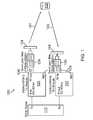
- FIG. 1illustrates a portable handheld radar system 100 in accordance with one or more embodiments.
- System 100may emit RF radiation 101 toward a target object 102 in a direction controlled by a user or operator (not shown), for example, by aiming a hand-held unit containing the radar system 100 . Further aiming or scanning of RF radiation 101 may also be accomplished by a beam forming array antenna 104 .
- the transmitter of the system 100may, for example, emit RF radiation 101 in the form of rapid wideband (narrow width) radar pulses at a chosen pulse repetition frequency (PRF) in the V band.
- PRFpulse repetition frequency
- the V band pulsescan penetrate glass, wood, soil, concrete, dry wall and bricks with varying attenuation constant.
- the radar system 100may, for example, transmit Gaussian pulses as short as 100 pico-seconds wide with center frequency in the V band. Radar system 100 may employ a correlator pulse detector circuit to identify reflections 103 of the radiation 101 . Amplitude and delay information may be extracted and processed in an integrated signal processor, for example, included in signal processing and imaging module of UWB radar unit 110 . Radar unit 110 , which may be a pre-existing, commercially available unit, may provide a display for a user including images for which image construction algorithms may be implemented using digital signal processing (DSP).
- DSPdigital signal processing
- Antenna 104may include a 16-by-1 active array antenna implemented using wafer scale antenna module technology.
- Wafer scale antenna modulesare disclosed by U.S. Patent Application Publication 20090102703, filed Oct. 18, 2007, to Mohamadi et al., and U.S. Patent Publication 20080252546, filed Oct. 31, 2006, to Mohamadi, which are both hereby incorporated by reference.
- Radar system 100may include V band transmit module 120 and receive module 122 .
- Transmit module 120 and receive module 122each have nominally 60 GHz center frequency, or local oscillator frequency for super-heterodyne frequency conversion, and therefore may also be referred to as “60 GHz” modules as well as “V band” modules.
- Each of 60 GHz transmit module 120 and 60 GHz receive module 122may produce or be responsive to frequencies in the range of about 53 GHz to 65 GHz, and may provide a wide band platform for transmission of the UWB spectrum of short impulses at 60 GHz.
- Transmit module 120 and receive module 122may be provided with a phase reference 123 , as shown in FIG. 1 .
- System 100may also include band pass filters 124 , 126 to select out unneeded sidebands produced by the super-heterodyne frequency conversion.
- system 100One operational purpose of system 100 is to provide a link at 60 GHz for transmission and reception of base band (e.g., UWB band) short impulses (as short as 100 pico-seconds) to be used for high precision radar applications. Another purpose of system 100 is to serve as a direct conversion system that modulates a base band short impulse 200 pico-seconds long (producing a spectrum 5 GHz wide) used in a 60 GHz radar front end.
- System 100may provide a 60 GHz platform that can be used with an existing 5 GHz UWB radar system that allows the existing 5 GHz UWB system to benefit from the practical size of a directive antenna at 60 GHz.
- Using the 60 GHz transmit module 120 and receive module 122 in tandem with the existing 5 GHz UWB radar systemcan provide a virtual narrow beam at 5 GHz which can improve the detection resolution without the need to use antenna arrays with impractical sizes at 5 GHz.
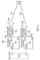
- FIG. 2is a system block diagram illustrating a V-band transmitter and receiver system 200 used in a direct conversion configuration using the same 60 GHz transmit module 120 and 60 GHz receive module 122 .
- System 200may include an impulse generator 210 connected to transmit module 120 .
- the impulse from impulse generator 210is up-converted by transmit module 120 , then transmitted and received through the 23 dB, 10 degrees beam width standard horn antennas 204 .
- the received reflections 103may be down-converted and fed to sampling scope 211 .
- FIG. 3illustrates a V-band transmitter and receiver system 300 with addition of components to system 200 to make use of an existing 5 GHz UWB radar 110 in accordance with an embodiment.
- the existing 5 GHz UWB radar 110can be used alongside the same V band modules 120 , 122 of system 200 in a super-heterodyne configuration.
- system 300may use band pass filters (and a circulator 106 at transmit module 120 ). If desired, the upper side band spectrum could be used instead by choosing different values for the band pass filter components.
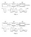
- FIG. 4 and FIG. 5are diagrams showing frequency spectrum graphs to illustrate the transmit and receive, respectively, operation of radar systems 100 , 200 , and 300 .
- the 60 GHz front ende.g., transmit module 120 and receive module 122
- the 5 GHz output 111 and 5 GHz input 112 of radar system 110may be approximately the same regardless of whether the 60 GHz front end is connected to or being used with radar system 110 .
- FIG. 4shows the frequency spectrum at the output of each stage of transmit; for example, spectrum 125 shows that a lower side band centered at about 56 GHz has been selected for transmission by the antenna 104 or antenna 204 , while an upper side band centered at about 66 GHz has been suppressed.
- FIG. 5shows the frequency spectrum at the input of each stage in the receive chain; for example, spectrum 127 shows the lower side band amplified while the upper side band is suppressed in this example embodiment, and conversion of the lower sideband via receive module 122 to the baseband spectrum 112 .
- V band front ende.g., transmit module 120 , receive module 122 , and band pass filters 124 , 126
- transmit module 120receive module 122 , and band pass filters 124 , 126
- band pass filters 124 , 126band pass filters
- FIG. 6is a block diagram illustrating a V band 16-by-1 active antenna array 600 , which may be used, for example, to implement active array antenna 104 of radar system 100 .
- the V band 16-by-1 active antenna array 600is the front-end unit to address the directivity enabler for beam forming within the proposed heterodyne structure.
- Each element 610 of array 600has its own dedicated amplifier 620 .
- Corporate combiningmay be used to implement a corporate distribution feed network 630 .
- the corporate distribution feed network 630may be symmetrical leading to the in-phase addition of the propagated wave from each element 610 .
- FIG. 7is a perspective diagram showing a physical arrangement of components for an active antenna array system 700 .
- System 700may include three separate boards and a reflector: a mother board 702 , an antenna board 704 , a power management board 706 and the reflector 708 .
- the mother board 702shown in FIG. 7 and FIG. 8 , hosts the MMIC (monolithic microwave integrated circuit) amplifiers 620 and the corporate distribution feed network 630 .
- Antenna board 704hosts the antenna elements 610 .
- Power management board 706hosts circuits to provide power management for the MMIC amplifiers.
- the antenna board 704may be wire-bonded to the mother board 702 as shown also, for example, in FIG. 8 .
- a laser cut trench 710may be devised on the mother board 702 .
- the trench 710may house 16 MMIC amplifiers 620 which are die attached to the substrate (e.g., mother board 702 ) and are fed through the corporate distribution feed network 630 .
- the corporate combining feeds (e.g., network 630 ) to antenna array 600are also shown in more detail in FIG. 8 .
- antenna board 704may be installed so that the continuity of the ground plane between the two boards—mother board 702 and antenna board 704 —is maintained.
- the antenna board 704may be installed on the pedestal using silver epoxy and then the lines connecting the two boards may be wire-bonded so that the antenna array on antenna board 704 is attached to the active distribution network (e.g., network 630 ) on motherboard 702 .
- the maximum dimension, or width, of the antenna array 600may be less than 2 inches.
- Active antenna array system 700may readily be implemented using WSAM methods incorporated by reference above.
- FIG. 9is block diagram for power management board 706 for an active antenna array system 700 .
- Power management board 706may be powered, for example, by a 5 V (volt) power input 7060 .
- Power management board 706may provide a sequenced DC bias to the MMIC amplifiers 620 as indicated in FIG. 9 by sequencing module 7061 , providing, for example, a 5 V bias sequencing for MMIC amplifiers 620 ; and sequencing module 7062 , providing, for example, a ⁇ 3 V bias sequencing for MMIC amplifiers 620 .
- power management board 706may be installed perpendicularly to both the motherboard 702 and the reflector 708 .
Landscapes
- Engineering & Computer Science (AREA)
- Radar, Positioning & Navigation (AREA)
- Remote Sensing (AREA)
- Computer Networks & Wireless Communication (AREA)
- Physics & Mathematics (AREA)
- General Physics & Mathematics (AREA)
- Variable-Direction Aerials And Aerial Arrays (AREA)
Abstract
Description
Claims (11)
Priority Applications (1)
| Application Number | Priority Date | Filing Date | Title |
|---|---|---|---|
| US12/718,896US8237604B2 (en) | 2009-03-06 | 2010-03-05 | Virtual beam forming in ultra wideband systems |
Applications Claiming Priority (2)
| Application Number | Priority Date | Filing Date | Title |
|---|---|---|---|
| US15830109P | 2009-03-06 | 2009-03-06 | |
| US12/718,896US8237604B2 (en) | 2009-03-06 | 2010-03-05 | Virtual beam forming in ultra wideband systems |
Publications (2)
| Publication Number | Publication Date |
|---|---|
| US20100225520A1 US20100225520A1 (en) | 2010-09-09 |
| US8237604B2true US8237604B2 (en) | 2012-08-07 |
Family
ID=42677773
Family Applications (1)
| Application Number | Title | Priority Date | Filing Date |
|---|---|---|---|
| US12/718,896Expired - Fee RelatedUS8237604B2 (en) | 2009-03-06 | 2010-03-05 | Virtual beam forming in ultra wideband systems |
Country Status (1)
| Country | Link |
|---|---|
| US (1) | US8237604B2 (en) |
Cited By (9)
| Publication number | Priority date | Publication date | Assignee | Title |
|---|---|---|---|---|
| US9110168B2 (en) | 2011-11-18 | 2015-08-18 | Farrokh Mohamadi | Software-defined multi-mode ultra-wideband radar for autonomous vertical take-off and landing of small unmanned aerial systems |
| US20150241552A1 (en)* | 2014-02-26 | 2015-08-27 | Farrokh Mohamadi | Wafer scale sensor ultra-wideband array for tissue diagnosis |
| US9329001B2 (en) | 2011-10-26 | 2016-05-03 | Farrokh Mohamadi | Remote detection, confirmation and detonation of buried improvised explosive devices |
| US9748645B2 (en) | 2013-06-04 | 2017-08-29 | Farrokh Mohamadi | Reconfigurable antenna with cluster of radiating pixelates |
| US11056799B2 (en) | 2014-02-13 | 2021-07-06 | Farrokh Mohamadi | W-band combiner-splitter fabricated using 3-D printing |
| US11181629B2 (en) | 2016-12-01 | 2021-11-23 | Carrier Corporation | Hand-held radar |
| US11344215B2 (en) | 2014-09-05 | 2022-05-31 | Farrokh Mohamadi | Handheld and portable scanners for millimeter wave mammography and instant mammography imaging |
| US11656334B2 (en) | 2018-03-23 | 2023-05-23 | Xonar Technology Inc. | System and method for detecting object patterns using ultra-wideband (UWB) radar |
| US20240103123A1 (en)* | 2021-02-03 | 2024-03-28 | Bitstrata Systems Inc. | Radar-based sensing, positioning, and communications system |
Families Citing this family (54)
| Publication number | Priority date | Publication date | Assignee | Title |
|---|---|---|---|---|
| US8873585B2 (en) | 2006-12-19 | 2014-10-28 | Corning Optical Communications Wireless Ltd | Distributed antenna system for MIMO technologies |
| US8644844B2 (en) | 2007-12-20 | 2014-02-04 | Corning Mobileaccess Ltd. | Extending outdoor location based services and applications into enclosed areas |
| CN102209921B (en) | 2008-10-09 | 2015-11-25 | 康宁光缆系统有限公司 | There is the fibre-optic terminus supported from the adapter panel of the input and output optical fiber of optical splitters |
| CN102369678B (en) | 2009-02-03 | 2015-08-19 | 康宁光缆系统有限责任公司 | Optical fiber based distributed antenna systems, assemblies and related methods for calibrating optical fiber based distributed antenna systems, assemblies |
| CN102396171B (en) | 2009-02-03 | 2015-09-30 | 康宁光缆系统有限责任公司 | Based on the distributing antenna system of optical fiber, assembly and the correlation technique for monitoring and configure distributing antenna system based on optical fiber, assembly |
| US9673904B2 (en) | 2009-02-03 | 2017-06-06 | Corning Optical Communications LLC | Optical fiber-based distributed antenna systems, components, and related methods for calibration thereof |
| US9590733B2 (en) | 2009-07-24 | 2017-03-07 | Corning Optical Communications LLC | Location tracking using fiber optic array cables and related systems and methods |
| US8280259B2 (en) | 2009-11-13 | 2012-10-02 | Corning Cable Systems Llc | Radio-over-fiber (RoF) system for protocol-independent wired and/or wireless communication |
| US8275265B2 (en) | 2010-02-15 | 2012-09-25 | Corning Cable Systems Llc | Dynamic cell bonding (DCB) for radio-over-fiber (RoF)-based networks and communication systems and related methods |
| US8573529B2 (en)* | 2010-03-01 | 2013-11-05 | Farrokh Mohamadi | Standoff detection of motion and concealed unexploded ordnance (UXO) |
| WO2011123336A1 (en) | 2010-03-31 | 2011-10-06 | Corning Cable Systems Llc | Localization services in optical fiber-based distributed communications components and systems, and related methods |
| US8570914B2 (en) | 2010-08-09 | 2013-10-29 | Corning Cable Systems Llc | Apparatuses, systems, and methods for determining location of a mobile device(s) in a distributed antenna system(s) |
| US9252874B2 (en) | 2010-10-13 | 2016-02-02 | Ccs Technology, Inc | Power management for remote antenna units in distributed antenna systems |
| WO2012054454A2 (en) | 2010-10-19 | 2012-04-26 | Corning Cable Systems Llc | Transition box for multiple dwelling unit fiber optic distribution network |
| WO2012148940A1 (en) | 2011-04-29 | 2012-11-01 | Corning Cable Systems Llc | Systems, methods, and devices for increasing radio frequency (rf) power in distributed antenna systems |
| WO2012148938A1 (en) | 2011-04-29 | 2012-11-01 | Corning Cable Systems Llc | Determining propagation delay of communications in distributed antenna systems, and related components, systems and methods |
| US9219546B2 (en) | 2011-12-12 | 2015-12-22 | Corning Optical Communications LLC | Extremely high frequency (EHF) distributed antenna systems, and related components and methods |
| US10110307B2 (en) | 2012-03-02 | 2018-10-23 | Corning Optical Communications LLC | Optical network units (ONUs) for high bandwidth connectivity, and related components and methods |
| US9119061B2 (en) | 2012-03-20 | 2015-08-25 | Farrokh Mohamadi | Integrated wafer scale, high data rate, wireless repeater placed on fixed or mobile elevated platforms |
| EP2832012A1 (en) | 2012-03-30 | 2015-02-04 | Corning Optical Communications LLC | Reducing location-dependent interference in distributed antenna systems operating in multiple-input, multiple-output (mimo) configuration, and related components, systems, and methods |
| US9316732B1 (en) | 2012-04-05 | 2016-04-19 | Farrokh Mohamadi | Standoff screening apparatus for detection of concealed weapons |
| US9781553B2 (en) | 2012-04-24 | 2017-10-03 | Corning Optical Communications LLC | Location based services in a distributed communication system, and related components and methods |
| WO2013162988A1 (en) | 2012-04-25 | 2013-10-31 | Corning Cable Systems Llc | Distributed antenna system architectures |
| US9244163B2 (en) | 2012-05-17 | 2016-01-26 | Farrokh Mohamadi | Integrated ultra wideband, wafer scale, RHCP-LHCP arrays |
| WO2014024192A1 (en) | 2012-08-07 | 2014-02-13 | Corning Mobile Access Ltd. | Distribution of time-division multiplexed (tdm) management services in a distributed antenna system, and related components, systems, and methods |
| US9455784B2 (en) | 2012-10-31 | 2016-09-27 | Corning Optical Communications Wireless Ltd | Deployable wireless infrastructures and methods of deploying wireless infrastructures |
| CN105308876B (en) | 2012-11-29 | 2018-06-22 | 康宁光电通信有限责任公司 | Remote unit antennas in distributing antenna system combines |
| US9647758B2 (en) | 2012-11-30 | 2017-05-09 | Corning Optical Communications Wireless Ltd | Cabling connectivity monitoring and verification |
| US9158864B2 (en) | 2012-12-21 | 2015-10-13 | Corning Optical Communications Wireless Ltd | Systems, methods, and devices for documenting a location of installed equipment |
| US20150285907A1 (en)* | 2013-05-03 | 2015-10-08 | Farrokh Mohamadi | Terahertz screening apparatus for detection of concealed weapons |
| CN105452951B (en) | 2013-06-12 | 2018-10-19 | 康宁光电通信无线公司 | Voltage type optical directional coupler |
| WO2014199380A1 (en) | 2013-06-12 | 2014-12-18 | Corning Optical Communications Wireless, Ltd. | Time-division duplexing (tdd) in distributed communications systems, including distributed antenna systems (dass) |
| US9247543B2 (en) | 2013-07-23 | 2016-01-26 | Corning Optical Communications Wireless Ltd | Monitoring non-supported wireless spectrum within coverage areas of distributed antenna systems (DASs) |
| US9661781B2 (en) | 2013-07-31 | 2017-05-23 | Corning Optical Communications Wireless Ltd | Remote units for distributed communication systems and related installation methods and apparatuses |
| US9383426B2 (en)* | 2013-09-17 | 2016-07-05 | Farrokh Mohamadi | Real-time, two dimensional (2-D) tracking of first responders with identification inside premises |
| US9385810B2 (en) | 2013-09-30 | 2016-07-05 | Corning Optical Communications Wireless Ltd | Connection mapping in distributed communication systems |
| US9178635B2 (en) | 2014-01-03 | 2015-11-03 | Corning Optical Communications Wireless Ltd | Separation of communication signal sub-bands in distributed antenna systems (DASs) to reduce interference |
| US9775123B2 (en) | 2014-03-28 | 2017-09-26 | Corning Optical Communications Wireless Ltd. | Individualized gain control of uplink paths in remote units in a distributed antenna system (DAS) based on individual remote unit contribution to combined uplink power |
| US9357551B2 (en) | 2014-05-30 | 2016-05-31 | Corning Optical Communications Wireless Ltd | Systems and methods for simultaneous sampling of serial digital data streams from multiple analog-to-digital converters (ADCS), including in distributed antenna systems |
| US9525472B2 (en) | 2014-07-30 | 2016-12-20 | Corning Incorporated | Reducing location-dependent destructive interference in distributed antenna systems (DASS) operating in multiple-input, multiple-output (MIMO) configuration, and related components, systems, and methods |
| US9730228B2 (en) | 2014-08-29 | 2017-08-08 | Corning Optical Communications Wireless Ltd | Individualized gain control of remote uplink band paths in a remote unit in a distributed antenna system (DAS), based on combined uplink power level in the remote unit |
| US9602210B2 (en) | 2014-09-24 | 2017-03-21 | Corning Optical Communications Wireless Ltd | Flexible head-end chassis supporting automatic identification and interconnection of radio interface modules and optical interface modules in an optical fiber-based distributed antenna system (DAS) |
| US9420542B2 (en) | 2014-09-25 | 2016-08-16 | Corning Optical Communications Wireless Ltd | System-wide uplink band gain control in a distributed antenna system (DAS), based on per band gain control of remote uplink paths in remote units |
| US9729267B2 (en) | 2014-12-11 | 2017-08-08 | Corning Optical Communications Wireless Ltd | Multiplexing two separate optical links with the same wavelength using asymmetric combining and splitting |
| US20160249365A1 (en) | 2015-02-19 | 2016-08-25 | Corning Optical Communications Wireless Ltd. | Offsetting unwanted downlink interference signals in an uplink path in a distributed antenna system (das) |
| US10634764B2 (en) | 2015-04-09 | 2020-04-28 | Corvus Technologies Corp | Beacon and associated components for a ranging system |
| US9681313B2 (en) | 2015-04-15 | 2017-06-13 | Corning Optical Communications Wireless Ltd | Optimizing remote antenna unit performance using an alternative data channel |
| US9948349B2 (en) | 2015-07-17 | 2018-04-17 | Corning Optical Communications Wireless Ltd | IOT automation and data collection system |
| US10560214B2 (en) | 2015-09-28 | 2020-02-11 | Corning Optical Communications LLC | Downlink and uplink communication path switching in a time-division duplex (TDD) distributed antenna system (DAS) |
| US9648580B1 (en) | 2016-03-23 | 2017-05-09 | Corning Optical Communications Wireless Ltd | Identifying remote units in a wireless distribution system (WDS) based on assigned unique temporal delay patterns |
| US10236924B2 (en) | 2016-03-31 | 2019-03-19 | Corning Optical Communications Wireless Ltd | Reducing out-of-channel noise in a wireless distribution system (WDS) |
| GB2558273A (en)* | 2016-12-23 | 2018-07-11 | Hohla Martin | Sensor system for a vehicle and method for determining assessment threat |
| US10976428B2 (en)* | 2017-02-14 | 2021-04-13 | The Trustees Of The Stevens Institute Of Technology | Synthetic ultra-wideband millimeter-wave imaging for tissue diagnostics |
| US12332335B2 (en) | 2021-06-10 | 2025-06-17 | The Trustees Of The Stevens Institute Of Technology | Synthetic ultrawideband integrated millimeter-wave imager |
Citations (22)
| Publication number | Priority date | Publication date | Assignee | Title |
|---|---|---|---|---|
| US4825215A (en)* | 1986-07-03 | 1989-04-25 | Hughes Aircraft Company | Radiometric imager having a frequency-dispersive linear array antenna |
| US5059927A (en)* | 1989-08-28 | 1991-10-22 | Ail Systems, Inc. | Microwave oscillator with reduced phase noise |
| US5121124A (en)* | 1991-05-01 | 1992-06-09 | Thermo Electron Technologies Corp. | Microwave camera |
| US5365237A (en)* | 1993-05-13 | 1994-11-15 | Thermo Trex Corporation | Microwave camera |
| US5446461A (en)* | 1994-04-28 | 1995-08-29 | Hughes Missile Systems Company | Concrete penetrating imaging radar |
| US20020171585A1 (en)* | 2001-05-07 | 2002-11-21 | Rafael-Armament Development Authority Ltd. | Planar ray imaging steered beam array (PRISBA) antenna |
| US20030022694A1 (en)* | 2001-05-02 | 2003-01-30 | Randall Olsen | Communication system with multi-beam communication antenna |
| US6707419B2 (en)* | 2000-08-16 | 2004-03-16 | Raytheon Company | Radar transmitter circuitry and techniques |
| US6937182B2 (en)* | 2001-09-28 | 2005-08-30 | Trex Enterprises Corp. | Millimeter wave imaging system |
| US20060039449A1 (en)* | 1997-05-16 | 2006-02-23 | Fontana Robert J | Ultra-wideband receiver and transmitter |
| US7019682B1 (en)* | 2005-04-12 | 2006-03-28 | Trex Enterprises Corp. | Imaging millimeter wave radar system |
| US7119621B2 (en)* | 2003-08-07 | 2006-10-10 | Ntt Docomo, Inc. | Power amplifier |
| US7224944B2 (en)* | 2004-01-22 | 2007-05-29 | Mcewan Technologies, Llc | RF transceiver having a directly radiating transistor |
| US7239262B2 (en)* | 2002-04-05 | 2007-07-03 | Osepchuk John M | Delivery of quasi-periodic pulses of EM energy utilizing the principle of beating-wave amplification |
| US7460055B2 (en)* | 2006-06-02 | 2008-12-02 | Panasonic Corporation | Radar apparatus |
| US7592943B2 (en)* | 2004-09-28 | 2009-09-22 | Qinetiq Limited | Frequency modulated continuous wave (FMCW) radar having improved frequency linearity |
| US7642929B1 (en)* | 2007-04-19 | 2010-01-05 | The United States Of America As Represented By The Secretary Of The Air Force | Helicopter brown-out landing |
| US20100001900A1 (en)* | 2006-08-02 | 2010-01-07 | Katsuyuki Imai | Radar |
| US7692571B2 (en)* | 2007-06-29 | 2010-04-06 | Trex Enterprises Corp. | Millimeter wave imager with visible or infrared overlay for brownout assist |
| US7773028B2 (en)* | 2006-12-06 | 2010-08-10 | Raytheon Company | Method and system for concatenation of radar pulses |
| US7783199B2 (en)* | 2006-11-13 | 2010-08-24 | Battelle Memorial Institute | Frequency selective MMW source |
| US7812760B2 (en)* | 2006-04-20 | 2010-10-12 | Anritsu Corporation | Short-range radar and control method thereof |
- 2010
- 2010-03-05USUS12/718,896patent/US8237604B2/ennot_activeExpired - Fee Related
Patent Citations (27)
| Publication number | Priority date | Publication date | Assignee | Title |
|---|---|---|---|---|
| US4825215A (en)* | 1986-07-03 | 1989-04-25 | Hughes Aircraft Company | Radiometric imager having a frequency-dispersive linear array antenna |
| US5059927A (en)* | 1989-08-28 | 1991-10-22 | Ail Systems, Inc. | Microwave oscillator with reduced phase noise |
| US5121124A (en)* | 1991-05-01 | 1992-06-09 | Thermo Electron Technologies Corp. | Microwave camera |
| US5365237A (en)* | 1993-05-13 | 1994-11-15 | Thermo Trex Corporation | Microwave camera |
| US5446461A (en)* | 1994-04-28 | 1995-08-29 | Hughes Missile Systems Company | Concrete penetrating imaging radar |
| US20060039449A1 (en)* | 1997-05-16 | 2006-02-23 | Fontana Robert J | Ultra-wideband receiver and transmitter |
| US7209523B1 (en)* | 1997-05-16 | 2007-04-24 | Multispectral Solutions, Inc. | Ultra-wideband receiver and transmitter |
| US7369598B2 (en)* | 1997-05-16 | 2008-05-06 | Multispectral Solutions, Inc. | Ultra-wideband receiver and transmitter |
| US6707419B2 (en)* | 2000-08-16 | 2004-03-16 | Raytheon Company | Radar transmitter circuitry and techniques |
| US20030022694A1 (en)* | 2001-05-02 | 2003-01-30 | Randall Olsen | Communication system with multi-beam communication antenna |
| US6680698B2 (en)* | 2001-05-07 | 2004-01-20 | Rafael-Armament Development Authority Ltd. | Planar ray imaging steered beam array (PRISBA) antenna |
| US20020171585A1 (en)* | 2001-05-07 | 2002-11-21 | Rafael-Armament Development Authority Ltd. | Planar ray imaging steered beam array (PRISBA) antenna |
| US6937182B2 (en)* | 2001-09-28 | 2005-08-30 | Trex Enterprises Corp. | Millimeter wave imaging system |
| US7239262B2 (en)* | 2002-04-05 | 2007-07-03 | Osepchuk John M | Delivery of quasi-periodic pulses of EM energy utilizing the principle of beating-wave amplification |
| US7119621B2 (en)* | 2003-08-07 | 2006-10-10 | Ntt Docomo, Inc. | Power amplifier |
| US7224944B2 (en)* | 2004-01-22 | 2007-05-29 | Mcewan Technologies, Llc | RF transceiver having a directly radiating transistor |
| US7592943B2 (en)* | 2004-09-28 | 2009-09-22 | Qinetiq Limited | Frequency modulated continuous wave (FMCW) radar having improved frequency linearity |
| US7019682B1 (en)* | 2005-04-12 | 2006-03-28 | Trex Enterprises Corp. | Imaging millimeter wave radar system |
| US7812760B2 (en)* | 2006-04-20 | 2010-10-12 | Anritsu Corporation | Short-range radar and control method thereof |
| US7460055B2 (en)* | 2006-06-02 | 2008-12-02 | Panasonic Corporation | Radar apparatus |
| US7609199B2 (en)* | 2006-06-02 | 2009-10-27 | Panasonic Corporation | Radar apparatus |
| US20100001900A1 (en)* | 2006-08-02 | 2010-01-07 | Katsuyuki Imai | Radar |
| US8018374B2 (en)* | 2006-08-02 | 2011-09-13 | Sumitomo Electric Industries, Ltd. | Radar |
| US7783199B2 (en)* | 2006-11-13 | 2010-08-24 | Battelle Memorial Institute | Frequency selective MMW source |
| US7773028B2 (en)* | 2006-12-06 | 2010-08-10 | Raytheon Company | Method and system for concatenation of radar pulses |
| US7642929B1 (en)* | 2007-04-19 | 2010-01-05 | The United States Of America As Represented By The Secretary Of The Air Force | Helicopter brown-out landing |
| US7692571B2 (en)* | 2007-06-29 | 2010-04-06 | Trex Enterprises Corp. | Millimeter wave imager with visible or infrared overlay for brownout assist |
Cited By (10)
| Publication number | Priority date | Publication date | Assignee | Title |
|---|---|---|---|---|
| US9329001B2 (en) | 2011-10-26 | 2016-05-03 | Farrokh Mohamadi | Remote detection, confirmation and detonation of buried improvised explosive devices |
| US9110168B2 (en) | 2011-11-18 | 2015-08-18 | Farrokh Mohamadi | Software-defined multi-mode ultra-wideband radar for autonomous vertical take-off and landing of small unmanned aerial systems |
| US9748645B2 (en) | 2013-06-04 | 2017-08-29 | Farrokh Mohamadi | Reconfigurable antenna with cluster of radiating pixelates |
| US11056799B2 (en) | 2014-02-13 | 2021-07-06 | Farrokh Mohamadi | W-band combiner-splitter fabricated using 3-D printing |
| US20150241552A1 (en)* | 2014-02-26 | 2015-08-27 | Farrokh Mohamadi | Wafer scale sensor ultra-wideband array for tissue diagnosis |
| US9372256B2 (en)* | 2014-02-26 | 2016-06-21 | Farrokh Mohamadi | Wafer scale sensor ultra-wideband array for tissue diagnosis |
| US11344215B2 (en) | 2014-09-05 | 2022-05-31 | Farrokh Mohamadi | Handheld and portable scanners for millimeter wave mammography and instant mammography imaging |
| US11181629B2 (en) | 2016-12-01 | 2021-11-23 | Carrier Corporation | Hand-held radar |
| US11656334B2 (en) | 2018-03-23 | 2023-05-23 | Xonar Technology Inc. | System and method for detecting object patterns using ultra-wideband (UWB) radar |
| US20240103123A1 (en)* | 2021-02-03 | 2024-03-28 | Bitstrata Systems Inc. | Radar-based sensing, positioning, and communications system |
Also Published As
| Publication number | Publication date |
|---|---|
| US20100225520A1 (en) | 2010-09-09 |
Similar Documents
| Publication | Publication Date | Title |
|---|---|---|
| US8237604B2 (en) | Virtual beam forming in ultra wideband systems | |
| US8368580B2 (en) | Electronic counter measure system | |
| US9213095B2 (en) | Combined direction finder and radar system, method and computer program product | |
| EP2131508A2 (en) | Multicode aperture transmitter/receiver | |
| Statnikov et al. | A 0.32 THz FMCW radar system based on low-cost lens-integrated SiGe HBT front-ends | |
| US7245264B2 (en) | High frequency module and array of the same | |
| CN113325417B (en) | Millimeter wave and terahertz multi-band radar detection imaging system and method | |
| CN110568430B (en) | Non-blind area ranging method and system for monopulse radar with protection channel | |
| KR101167906B1 (en) | Radar system for vehicle and method for detecting targets using radar sysem | |
| CN109916241A (en) | A monolithic integrated millimeter wave fuze detector | |
| Statnikov et al. | A lens-coupled 210–270 GHz circularly polarized FMCW radar transceiver module in SiGe technology | |
| CN113589273B (en) | Millimeter wave/infrared active and passive imaging detection device and method | |
| US6768963B2 (en) | Geo-location systems | |
| Yuan et al. | Compact 120–140 GHz radar Tx/Rx sensors with on-chip antenna | |
| Heino et al. | On the prospects of in-band full-duplex radios as monostatic continuous-wave noise radars | |
| KR20120106567A (en) | Radar apparatus supporting short and long range radar operation | |
| KR101912519B1 (en) | Hybrid microwave imaging system and operating method thereof | |
| Grüner et al. | Enhancing angle estimation accuracy of ultra compact two-channel radar MMICs at 160 GHz using a biomimetic antenna array | |
| Wilden et al. | MIRA-CLE, an experimental MIMO radar in Ka band | |
| Shen et al. | IR-UWB-based chipless RFID system | |
| JP2008249498A (en) | Radar system | |
| RU2659611C1 (en) | Ultra-wideband active antenna array with electronic scanning | |
| Kanno et al. | 300-GHz versatile transceiver front-end for both communication and imaging | |
| Smith et al. | Ranging and target detection performance through lossy media using an ultrawideband S-band through-wall sensing noise radar | |
| Feng et al. | UWB Microwave Photonic Noise MIMO Radar for Through-Wall Ranging and Imaging |
Legal Events
| Date | Code | Title | Description |
|---|---|---|---|
| AS | Assignment | Owner name:TIALINX, INC., CALIFORNIA Free format text:ASSIGNMENT OF ASSIGNORS INTEREST;ASSIGNORS:MOHAMADI, FARROKH;ZOLGHADRI, MOHSEN;REEL/FRAME:024144/0425 Effective date:20100305 | |
| ZAAA | Notice of allowance and fees due | Free format text:ORIGINAL CODE: NOA | |
| ZAAB | Notice of allowance mailed | Free format text:ORIGINAL CODE: MN/=. | |
| STCF | Information on status: patent grant | Free format text:PATENTED CASE | |
| FPAY | Fee payment | Year of fee payment:4 | |
| MAFP | Maintenance fee payment | Free format text:PAYMENT OF MAINTENANCE FEE, 8TH YR, SMALL ENTITY (ORIGINAL EVENT CODE: M2552); ENTITY STATUS OF PATENT OWNER: SMALL ENTITY Year of fee payment:8 | |
| FEPP | Fee payment procedure | Free format text:MAINTENANCE FEE REMINDER MAILED (ORIGINAL EVENT CODE: REM.); ENTITY STATUS OF PATENT OWNER: SMALL ENTITY | |
| LAPS | Lapse for failure to pay maintenance fees | Free format text:PATENT EXPIRED FOR FAILURE TO PAY MAINTENANCE FEES (ORIGINAL EVENT CODE: EXP.); ENTITY STATUS OF PATENT OWNER: SMALL ENTITY | |
| STCH | Information on status: patent discontinuation | Free format text:PATENT EXPIRED DUE TO NONPAYMENT OF MAINTENANCE FEES UNDER 37 CFR 1.362 | |
| FP | Lapsed due to failure to pay maintenance fee | Effective date:20240807 |