US8237451B2 - Communicating with an implanted wireless sensor - Google Patents
Communicating with an implanted wireless sensorDownload PDFInfo
- Publication number
- US8237451B2 US8237451B2US13/078,091US201113078091AUS8237451B2US 8237451 B2US8237451 B2US 8237451B2US 201113078091 AUS201113078091 AUS 201113078091AUS 8237451 B2US8237451 B2US 8237451B2
- Authority
- US
- United States
- Prior art keywords
- signal
- sensor
- energizing
- frequency
- resonant frequency
- Prior art date
- Legal status (The legal status is an assumption and is not a legal conclusion. Google has not performed a legal analysis and makes no representation as to the accuracy of the status listed.)
- Expired - Lifetime
Links
Images


Classifications
- G—PHYSICS
- G01—MEASURING; TESTING
- G01R—MEASURING ELECTRIC VARIABLES; MEASURING MAGNETIC VARIABLES
- G01R23/00—Arrangements for measuring frequencies; Arrangements for analysing frequency spectra
- G01R23/02—Arrangements for measuring frequency, e.g. pulse repetition rate; Arrangements for measuring period of current or voltage
- G01R23/12—Arrangements for measuring frequency, e.g. pulse repetition rate; Arrangements for measuring period of current or voltage by converting frequency into phase shift
- A—HUMAN NECESSITIES
- A61—MEDICAL OR VETERINARY SCIENCE; HYGIENE
- A61B—DIAGNOSIS; SURGERY; IDENTIFICATION
- A61B5/00—Measuring for diagnostic purposes; Identification of persons
- A61B5/0002—Remote monitoring of patients using telemetry, e.g. transmission of vital signals via a communication network
- A61B5/0031—Implanted circuitry
- A—HUMAN NECESSITIES
- A61—MEDICAL OR VETERINARY SCIENCE; HYGIENE
- A61B—DIAGNOSIS; SURGERY; IDENTIFICATION
- A61B5/00—Measuring for diagnostic purposes; Identification of persons
- A61B5/05—Detecting, measuring or recording for diagnosis by means of electric currents or magnetic fields; Measuring using microwaves or radio waves
- G—PHYSICS
- G01—MEASURING; TESTING
- G01D—MEASURING NOT SPECIALLY ADAPTED FOR A SPECIFIC VARIABLE; ARRANGEMENTS FOR MEASURING TWO OR MORE VARIABLES NOT COVERED IN A SINGLE OTHER SUBCLASS; TARIFF METERING APPARATUS; MEASURING OR TESTING NOT OTHERWISE PROVIDED FOR
- G01D21/00—Measuring or testing not otherwise provided for
- G—PHYSICS
- G01—MEASURING; TESTING
- G01F—MEASURING VOLUME, VOLUME FLOW, MASS FLOW OR LIQUID LEVEL; METERING BY VOLUME
- G01F15/00—Details of, or accessories for, apparatus of groups G01F1/00 - G01F13/00 insofar as such details or appliances are not adapted to particular types of such apparatus
- G01F15/06—Indicating or recording devices
- G01F15/065—Indicating or recording devices with transmission devices, e.g. mechanical
- G01F15/066—Indicating or recording devices with transmission devices, e.g. mechanical involving magnetic transmission devices
- G—PHYSICS
- G01—MEASURING; TESTING
- G01R—MEASURING ELECTRIC VARIABLES; MEASURING MAGNETIC VARIABLES
- G01R23/00—Arrangements for measuring frequencies; Arrangements for analysing frequency spectra
- G01R23/02—Arrangements for measuring frequency, e.g. pulse repetition rate; Arrangements for measuring period of current or voltage
- G01R23/14—Arrangements for measuring frequency, e.g. pulse repetition rate; Arrangements for measuring period of current or voltage by heterodyning; by beat-frequency comparison
- G01R23/145—Arrangements for measuring frequency, e.g. pulse repetition rate; Arrangements for measuring period of current or voltage by heterodyning; by beat-frequency comparison by heterodyning or by beat-frequency comparison with the harmonic of an oscillator
- A—HUMAN NECESSITIES
- A61—MEDICAL OR VETERINARY SCIENCE; HYGIENE
- A61B—DIAGNOSIS; SURGERY; IDENTIFICATION
- A61B2560/00—Constructional details of operational features of apparatus; Accessories for medical measuring apparatus
- A61B2560/02—Operational features
- A61B2560/0204—Operational features of power management
- A61B2560/0214—Operational features of power management of power generation or supply
- A61B2560/0219—Operational features of power management of power generation or supply of externally powered implanted units
- A—HUMAN NECESSITIES
- A61—MEDICAL OR VETERINARY SCIENCE; HYGIENE
- A61B—DIAGNOSIS; SURGERY; IDENTIFICATION
- A61B2560/00—Constructional details of operational features of apparatus; Accessories for medical measuring apparatus
- A61B2560/02—Operational features
- A61B2560/0223—Operational features of calibration, e.g. protocols for calibrating sensors
- A—HUMAN NECESSITIES
- A61—MEDICAL OR VETERINARY SCIENCE; HYGIENE
- A61B—DIAGNOSIS; SURGERY; IDENTIFICATION
- A61B5/00—Measuring for diagnostic purposes; Identification of persons
- A61B5/07—Endoradiosondes
- A61B5/076—Permanent implantation
Definitions
- the present inventionis directed in general to communicating with a wireless sensor, and in particular to communicating with a wireless sensor implanted within the body to measure a physical condition.
- Wireless sensorscan be implanted within the body and used to monitor physical conditions, such as pressure or temperature.
- U.S. Pat. No. 6,111,520, U.S. Pat. No. 6,855,115 and U.S. Pat. No. 7,699,059each of which is incorporated herein by reference, all describe wireless sensors that can be implanted within the body. These sensors can be used to monitor physical conditions within the heart or an abdominal aneurysm.
- An abdominal aortic aneurysmis a dilatation and weakening of the abdominal aorta that can lead to aortic rupture and sudden death.
- a sensorcan be used to monitor pressure within the aneurysm sac to determine whether the intervention is leaking.
- the standard treatment for AAAsemploys the use of stent-grafts that are implanted via endovascular techniques.
- a significant problem that has emerged with these stein-grafts for AAAsis acute and late leaks of blood into the aneurysms sac.
- abdominal CTComputed Tomography
- IV contrastto identify the potential presence of stent-graft leaks. This is an expensive, risky procedure that lacks appropriate sensitivity to detect small leaks.
- the sensorsutilize an inductive-capacitive (“LC”) resonant circuit with a variable capacitor.
- the capacitance of the circuitvaries with the pressure of the environment, in which the sensor is located and thus, the resonant frequency of the circuit varies as the pressure varies.
- the resonant frequency of the circuitcan be used to calculate pressure.
- the resonant frequencyis determined using a non-invasive procedure.
- procedures for determining the resonant frequency of an implanted sensorare discussed in U.S. Pat. No. 6,111,520.
- Some of the procedures described in the patentrequire the transmission of a signal having multiple frequencies.
- a drawback of using a transmission signal having multiple frequenciesis that the energy in the frequency bands outside the resonant frequency is wasted. This excess energy requires more power which results in an increase in cost, size, and thermal requirements, as well as an increase in electromagnetic interference with other signals.
- the systemmust operate in a low power environment and must be capable of handling a signal from the sensor with certain characteristics.
- the signal from the sensoris relatively weak and must be detected quickly because the signal dissipates quickly.
- These requirementsalso impact the way that common problems are handled by the system. For example, the problems of switching transients and false locking need to be handled in a manner that accommodates the sensor signal characteristics.
- a method for communicating with a wireless sensorthat operates in a low power environment and that efficiently determines the resonant frequency of the sensor.
- the resonant frequency of the sensoris a measured parameter that is correlated with the physical parameter of interest. To be clinically useful there must be means to ensure that variations in measurement environment do not affect the accuracy of the sensor. Thus, there is a need for a system and method for communicating with a wireless sensor that considers variations in the measurement environment.
- aneurysm treatmentThe primary goal of aneurysm treatment is to depressurize the sac and to prevent rupture. Endoleaks, whether occurring intraoperatively or postoperatively, can allow the aneurysmal sac to remain pressurized and therefore, increase the chance of aneurysm rupture.
- the current imaging modalities angiography and CT scanare not always sensitive enough to detect endoleaks or stent graft failure.
- Intrasac pressure measurementsprovide a direct assessment of sac exclusion from circulation and may therefore offer intraoperative and post operative surveillance advantages that indirect imaging studies do not.
- an AAA pressure sensoris placed into the aneurysm sac at the time of stent-graft insertion.
- the pressure readingsare read out by the physician by holding an electronic instrument, which allows an immediate assessment of the success of the stent-graft at time of the procedure and outpatient follow-up visits, by reading the resonant frequency of the wireless sensor and correlating the frequency reading to pressure.
- the present inventionmeets the needs described above by providing a system and method for communicating with a wireless sensor to determine the resonant frequency of the sensor.
- the systemenergizes the sensor with a low duty cycle, gated burst of RF energy having a predetermined frequency or set of frequencies and a predetermined amplitude.
- the energizing signalis coupled to the sensor via a magnetic loop.
- the sensormay be an inductive-capacitive (“LC”) resonant circuit with a variable capacitor that is implanted within the body and used to measure physical parameters, such as pressure or temperature.
- the energizing signalinduces a current in the sensor which is maximized when the energizing frequency is the same as the resonant frequency of the sensor.
- the systemreceives the ring down response of the sensor via magnetic coupling and determines the resonant frequency of the sensor, which is used to calculate the measured physical parameter.
- a pair of phase locked loops(“PLLs”) is used to adjust the phase and the frequency of the energizing signal until its frequency locks to the resonant frequency of the sensor.
- PLLsphase locked loops
- the calibration cycleadjusts the phase of the energizing signal to a fixed reference phase to compensate for system delay or varying environmental conditions.
- the environmental conditions that can affect the accuracy of the sensor readinginclude, but are not limited to proximity of reflecting or magnetically absorptive objects, variation of reflecting objects located within transmission distance, variation of temperature or humidity which can change parameters of internal components, and aging of internal components.
- One of the PLLsis used to adjust the phase of the energizing signal and is referred to herein as the fast PLL.
- the other PLLis used to adjust the frequency of the energizing signal and is referred to herein as the slow PLL.
- a portion of the signalenters the receiver and is referred to herein as a calibration signal.
- the calibration signalis processed and sampled to determine the phase difference between its phase and the phase of a local oscillator (referred to herein as the local oscillator 2 ).
- the cycle in which the calibration signal is sampledis referred to as the calibration cycle.
- the systemadjusts the phase of the energizing signal to drive the phase difference to zero or another reference phase.
- the signal coupled from the sensor(referred to herein as the coupled signal or the sensor signal) is processed and sampled to determine the phase difference between the coupled signal and the energizing signal.
- the systemthen adjusts the frequency of the energizing signal to drive the phase difference to zero or other reference phase.
- the frequency of the energizing signalis deemed to match the resonant frequency of the sensor.
- the operation of the slow PLLis qualified based on signal strength so that the slow PLL does not lock unless the strength of the coupled signal meets a predetermined signal strength threshold.
- the systemalso handles false locking and switching transients.
- a false lockoccurs if the system locks on a frequency that does not correspond to the resonant frequency of the sensor.
- the systemavoids false locks by examining how the phase difference signal goes to zero. If the slope of the phase difference signal relative to time meets a predetermined direction, e.g. positive, then the PLL is allowed to lock. However, if the slope of the phase difference signal relative to time does not meet the predetermined direction, e.g. it is negative, then the signal strength is suppressed to prevent a false lock.
- Another aspect of the inventionuses frequency dithering to avoid a false lock.
- a constant pulse repetition frequencycan add spectral components to the sensor signal and cause a false lock.
- the sidebandsmove back and forth so that the average of the sidebands is reduced.
- the systemlocks on the center frequency rather than the sidebands.
- phase ditheringcan be used to reduce switching transients.
- the phase of the energizing signal and a local oscillator(referred to herein as local oscillator 1 ) are randomly changed. Varying the phase of the energizing signal varies the phase of the coupled signal, but does not affect the phase of the transient signal. Thus, the average of the transient signal is reduced.
- Changing the resonant frequency of the coil as it is switched from energizing mode to coupling modealso reduces switching transients.
- the capacitors that are connected to the coilare switched between different modes to slightly change the resonant frequency in order to reduce switching transients.
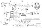
- FIG. 1is a block diagram of an exemplary system for communicating with a wireless sensor in accordance with an embodiment of the invention.
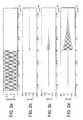
- FIG. 2( a )is a graph illustrating an exemplary energizing signal in accordance with an embodiment of the invention.
- FIGS. 2( b ), 2 ( c ) and 2 ( d )are graphs illustrating exemplary coupled signals in accordance with an embodiment of the invention.
- FIG. 3is a block diagram of an exemplary base unit in accordance with an embodiment of the invention.
- FIGS. 4( a ) and 4 ( b )are graphs illustrating exemplary phase difference signals in accordance with an embodiment of the invention.
- FIG. 5illustrates frequency dithering, in accordance with an embodiment of the invention.
- FIG. 6illustrates phase dithering in accordance with an embodiment of the invention.
- FIG. 7illustrates a coupling loop in accordance with an embodiment of the invention.
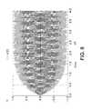
- FIG. 8is a graph illustrating an exemplary charging response of an LC circuit in accordance with an embodiment of the invention.
- the present inventionis directed towards a system and method for communicating with a wireless sensor. Briefly described, the present invention determines the resonant frequency of the sensor by adjusting the phase and frequency of an energizing signal until the frequency of this signal locks to the resonant frequency of the sensor.
- the systemenergizes the sensor with a low duty cycle, gated burst of RF energy of a predetermined frequency or set of frequencies and predetermined amplitude. This signal induces a current in the sensor that can be used to track the resonant frequency of the sensor.
- the systemreceives the ring down response of the sensor and determines the resonant frequency of the sensor, which is used to calculate the measured physical parameter.
- the systemuses a pair of phase locked loops (“PLL”s) to adjust the phase and the frequency of the energizing signal to track the resonant frequency of the sensor.
- PLLphase locked loops
- FIG. 1illustrates an exemplary system for communicating with a wireless sensor implanted within a body.
- the systemincludes a coupling loop 100 , a base unit 102 , a display device 104 and an input device 106 , such as a keyboard.
- the coupling loopis formed from a band of copper. In one embodiment, the loop is eight inches in diameter.
- the coupling loopincludes switching and filtering circuitry that is enclosed within a shielded box 101 .
- the loopcharges the sensor and then couples signals from the sensor into the receiver.
- the antennacan be shielded to attenuate in-band noise and electromagnetic emissions.
- FIG. 7shows separate loops for energizing 702 and for receiving 704 , although a single loop can be used for both functions.
- PIN diode switching inside the loop assemblyis used to provide isolation between the energizing phase and the receive phase by opening the RX path pin diodes during the energizing period, and opening the energizing path pin diodes during the coupling period.
- Multiple energizing, loopscan be staggered tuned to achieve a wider bandwidth of matching between the transmit coils and the transmit circuitry.
- the base unitincludes an RF amplifier, a receiver, and signal processing circuitry. Additional details of the circuitry are described below in connection with FIG. 3 .
- the display 104 and the input, device 106are used in connection with the user interface for the system.
- the display device and the input deviceare connected to the base unit.
- the base unitalso provides conventional computing, functions.
- the base unitcan be connected to a conventional computer, such as a laptop, via a communications link, such as an RS-232 link. If a separate computer is used, then the display device and the input devices associated with the computer can be used to provide the user interface, in one embodiment, LABVIEW software is used to provide the user interface, as well as to provide graphics, store and organize data and perform calculations for calibration and normalization.
- the user interfacerecords and displays patient data and guides the user through surgical and follow-up procedures.
- An optional printer 108is connected to the base unit and can be used to print out patient data or other types of information. As will be apparent to those skilled in the art other configurations of the system, as well as additional or fewer components can be utilized with the invention.
- Patient and system informationcan be stored within a removable data storage unit, such as a portable USB storage device, floppy disk, smart card, or any other similar device.
- the patient informationcan be transferred to the physician's personal computer for analysis, review, or storage.
- An optional network connectioncan be provided to automate storage or data transfer.
- a custom or third party sourcecan be employed to assist the physician with data analysis or storage.
- FIG. 1illustrates the system communicating with a sensor 120 implanted in a patient.
- the systemis used in two environments: 1) the operating room during implant and 2) the doctor's office during follow-up examinations.
- the systemis used to record at least two measurements.
- the first measurementis taken during introduction of the sensor for calibration and the second measurement is taken after placement for functional verification.
- the measurementscan be taken by placing the coupling loop either on or adjacent to the patient's hack or the patient's stomach for a sensor that measures properties associated with an abdominal, aneurysm.
- the coupling loopmay be placed in other locations.
- the coupling loopcan be placed on the patient's back or the patient's chest.
- a sensortypically includes an inductive-capacitive (“LC”) resonant circuit having a variable capacitor.
- LCinductive-capacitive
- the distance between the plates of the variable capacitorvaries as the surrounding pressure varies.
- the resonant frequency of the circuitcan be used to determine the pressure.
- the systemenergizes the sensor with an RF burst.
- the energizing signalis a low duty cycle, gated burst of RF energy of a predetermined frequency or set of frequencies and a predetermined amplitude.
- the duty cycle of the energizing signalranges from 0.1% to 50%.
- the systemenergizes the sensor with a 30-37 MHz fundamental signal at a pulse repetition rate of 100 kHz with a duty cycle of 20%.
- the energizing signalis coupled to the sensor via a magnetic loop. This signal induces a current in the sensor which has maximum amplitude at the resonant frequency of the sensor.
- FIG. 8shows the charging response of a typical LC circuit to a burst of RF energy at its resonant frequency.
- the speed at which the sensor chargesis directly related to the Q (quality factor) of the sensor. Therefore, the “on time” of the pulse repetition duty cycle is optimized for the Q of the sensor.
- the systemreceives the ring down response of the sensor via magnetic coupling and determines the resonant frequency of the sensor.
- FIG. 2( a )illustrates a typical energizing signal and FIGS.
- 2( b ), 2 ( c ) and 2 ( d )illustrate typical coupled signals for various values of Q (quality factor) for the sensor.
- Qquality factor
- FIG. 3is a block diagram of the signal processing components within an exemplary base unit.
- the base unitdetermines the resonant frequency of the sensor by adjusting the energizing signal so that the frequency of the energizing signal matches the resonant frequency of the sensor.
- two separate processors 302 , 322 and two separate coupling loops 340 , 342are shown.
- processor 302is associated with the base unit and processor 322 is associated with a computer connected to the base unit.
- a single processoris used that provides the same functions as the two separate processors.
- a single loopis used for both energizing and for coupling the sensor energy back to the receiver.
- other configurations of the base unitare possible that use different components.
- the embodiment illustrated by FIG. 3includes a pair of phase lock loops (“PLL”).
- PLLphase lock loops
- One of the PLLsis used to adjust the phase of the energizing signal and is referred to herein as the fast PLL.
- the other PLLis used to adjust the frequency of the energizing signal and is referred to herein as the slow PLL.
- the base unitprovides two cycles: the calibration cycle and the measurement cycle.
- the first cycleis a 10 microsecond energizing period for calibration of the system, which is referred to herein as the calibration cycle
- the second cycleis a 10 microsecond energizing/coupling period for energizing the sensor and coupling a return signal from the sensor, which is referred to herein as the measurement cycle.
- the systemDuring the calibration cycle, the system generates a calibration signal for system and environmental phase calibration and during the measurement cycle the system both sends and listens for a return signal, i.e. the sensor ring down.
- a return signali.e. the sensor ring down.
- the calibration cycle and the measurement cyclecan be implemented in the same pulse repetition period.
- the phase of the energizing signalis adjusted during the calibration cycle by the fast PLL and the frequency of the energizing signal is adjusted during the measurement cycle by the slow PLL.
- the following description of the operation of the PLLsis presented sequentially for simplicity. However, as those skilled in the art will appreciate, the PLLs actually operate simultaneously.
- the frequency of the energizing signalis set to a default value determined by the calibration parameters of the sensor.
- Each sensoris associated with a number of calibration parameters, such as frequency, offset, and slope.
- An operator of the systementers the sensor calibration parameters into the system via the user interface and the system determines an initial frequency for the energizing signal based on the particular sensor.
- the sensor calibration informationcould be stored on portable storage devices, bar codes, or incorporated within a signal returned from the sensor.
- the initial phase of the energizing signalis arbitrary.
- the initial frequency and the initial phaseare communicated from the processor 302 to the DDSs (direct digital synthesizers) 304 , 306 .
- the output of DDS 1 304is set to the initial frequency and initial phase and the Output of DDS 2 306 (also referred to as local oscillator 1 ) is set to the initial frequency plus the frequency of the local oscillator 2 .
- the phase of DDS 2is a fixed constant. In one embodiment, the frequency of local oscillator 2 is 4.725 MHz.
- the output of DDS 1is gated by the field programmable gate array (FPGA) 308 to create a pulsed transmit signal having a pulse repetition frequency (“PRF”).
- PRFpulse repetition frequency
- the calibration signal which enters the receiver 310is processed through the receive section 311 and the IF section 312 , and is sampled.
- the calibration signalis the portion of the energizing signal that leaks into the receiver (referred to herein as the energizing leakage signal).
- the signalis sampled during the on time of the energizing signal by a sample and hold circuit 314 to determine the phase difference between the signal and local oscillator 2 .
- the calibration signalis the portion of the energizing signal that leaks into the receiver, the signal is sampled approximately 100 ns after the beginning of the energizing signal pulse.
- the energizing signalis several orders of magnitude greater than the coupled signal, it is assumed that the phase information associated with the leaked signal is due to the energizing signal and the phase delay is due to the circuit elements in the coupling loop, circuit elements in the receiver, and environmental conditions, such as proximity of reflecting objects.
- the phase differenceis sent to a loop filter 316 .
- the loop filteris set for the dynamic response of the first PLL.
- the PLL bandwidthis 1000 Hz and the damping ratio is 0.7.
- a DC offsetis added to allow for positive and negative changes.
- the processor 302reads its analog to digital converter (A/D) port to receive the phase difference information and adjusts the phase sent to direct digital synthesizer 1 (DDS 1 ) to drive the phase difference to zero. This process is repeated alternatively until the phase difference is zero or another reference phase.
- A/Danalog to digital converter
- phase adjustment made during the energizing periodacts to zero the phase of the energizing signal with respect to local oscillator 2 .
- Changes in the environment of the antenna or the receive chain impedance, as well as the phase delay within the circuitry prior to samplingaffect the phase difference reading and are accommodated by the phase adjustment.
- the energizing signalmay be blocked from the receiver during the on time of the energizing signal.
- the receiveris unblocked and the coupled signal from the sensor (referred to herein as the coupled signal or the sensor signal) is received.
- the coupled signalis amplified and filtered through the receive section 311 .
- the signalis down converted and additional amplification and filtering takes place in the IF section 312 .
- the signalis down converted to 4.725 MHz.
- the signalis mixed with local oscillator 2 and sampled by sample and hold circuits 315 to determine the phase difference between the coupled signal and the energizing signal. In one embodiment, the sampling occurs approximately 30 ns after the energizing signal is turned off.
- group delay or signal amplitudeis used to determine the resonant frequency of the sensor.
- the phase curve of a second order systempasses through zero at the resonant frequency. Since the group delay i.e. derivative of the phase curve reaches a maximum at the resonant frequency, the group delay can be used to determine the resonant frequency.
- the amplitude of the sensor signalcan be used to determine the resonant frequency.
- the sensoracts like a bandpass filter so that the sensor signal reaches a maximum at the resonant frequency.
- the sampled signalis accumulated within a loop filter 320 .
- the loop filteris set for the dynamic response of the slow PLL to aid in the acquisition of a lock by the slow PLL.
- the PLLsare implemented with op-amp low pass filters that feed A/D inputs on microcontrollers, 302 and 322 , which in turn talk to the DDSs, 304 and 306 , which provide the energizing signal and local oscillator 1 .
- the microcontroller that controls the energizing DDS 304also handles communication with the display.
- the response of the slow PLLdepends upon whether the loop is locked or not. If the loop is unlocked, then the bandwidth is increased so that the loop will lock quickly.
- the slow PLLhas a damping ratio of 0.7 and a bandwidth of 120 Hz when locked (the Nyquist frequency of the blood pressure waveform), which is approximately ten times slower than the fast PLL.
- a DC offsetis also added to the signal to allow both a positive and a negative swing.
- the output of the loop filteris input to an A/D input of processor 322 .
- the processordetermines a new frequency and sends the new frequency to the DSSs.
- the processoroffsets the current frequency value of the energizing signal by an amount that is proportional to the amount needed to drive the output of the slow PLL loop filter to a preset value.
- the preset valueis 2.5V and zero in phase.
- the proportional amountis determined by the PLL's overall transfer function.
- the frequency of the energizing signalis deemed to match the resonant frequency of the sensor when the slow PLL is locked.
- the physical parametersuch as pressure, is calculated using the calibration parameters associated with the sensor, which results in a difference frequency that is proportional to the measured pressure.
- the operation of the slow PLLis qualified based on signal strength.
- the base unitincludes signal strength detection circuitry. If the received signal does not meet a predetermined signal strength threshold, then the slow PLL is not allowed to lock and the bandwidth and search window for the PLL are expanded. Once the received signal meets the predetermined signal strength threshold, then the bandwidth and search window of the slow PLL is narrowed and the PLL can lock.
- phase detection, and signal strength determinationare provided via the “I” (in phase) and “Q” (quadrature) channels of a quadrature mixer circuit.
- the “I” channelis lowpass filtered and sampled to provide signal strength information to the processing circuitry.
- the “Q” channelis lowpass filtered and sampled to provide phase error information to the slow PLL.
- a false lockoccurs if the system locks on a frequency that does not correspond to the resonant frequency of the sensor.
- the first type of false lockarises due to the pulsed nature of the system. Since the energizing signal is a pulsed signal, it includes groups of frequencies. The frequency that corresponds to a false lock is influenced by the pulse repetition frequency, the Q of the sensor, and the duty cycle of the RF burst. For example, a constant pulse repetition frequency adds spectral components to the return signal at harmonic intervals around the resonant frequency of the sensor, which can cause a false lock. In one embodiment, false locks occur at approximately 600 kHz above and below the resonant frequency of the sensor.
- the characteristics of the signalare examined. For example, pulse repetition frequency dithering and/or observing the slope of the baseband signal are two possible ways of determine a false lock.
- the signal characteristicscorrespond to a heartbeat or a blood pressure waveform.
- the second type of false lockarises due to a reflection or resonance of another object in the vicinity of the system.
- This type of false lockcan be difficult to discern because it generally does not correspond to a heartbeat or blood pressure waveform.
- the lack of frequency modulationcan be used to discriminate against this type of false lock.
- Changing the orientation of the magnetic loopalso affects this type of false lock because the reflected false lock is sensitive to the angle of incidence.
- the third type of false lockarises due to switching transients caused by switching the PIN diodes and analog switches in the RF path. These transients cause damped resonances in the filters in the receive chain, which can appear similar to the sensor signal. Typically, these types of false locks do not correspond to a heartbeat or blood pressure waveform because they are constant frequency. These types of false locks are also insensitive to orientation of the magnetic loop.
- the present inventiondetermines the slope of the baseband signal (the phase difference signal at point 330 ). In, one embodiment, if the slope is positive, then the lock is deemed a true lock. However, if the slope is negative, then the lock is deemed a false lock. In another embodiment, a negative slope is deemed a true lock and a positive slope is deemed a false lock. The slope is determined by looking at points before and after the phase difference signal goes to zero. The slope can be determined in a number of different ways, including but not limited to, using an analog differentiator or multiple sampling. FIGS. 4( a ) and 4 ( b ) illustrate a true lock and a false lock respectively, when a positive slope indicates a true lock.
- any non-zero slopecan be interpreted as a false lock resulting in zero signal strength.
- the systemcan also use frequency dithering to avoid the first type of false lock. Since the spectral components associated with a constant pulse repetition frequency can cause a false lock, dithering the pulse repetition frequency helps avoid a false lock. By dithering the pulse repetition frequency, the spectral energy at the potential false lock frequencies is reduced over the averaged sampling interval.
- the energizing signalincludes an on time t 1 and an off time t 2 .
- the systemcan vary the on time or the off time to vary the PRF (PRF 1/(t 1 +t 2 )).
- FIG. 5illustrates different on times (t 1 , t 1 ′) and different off times (t 2 , t 2 ′).
- the PRFcan be varied between predetermined sequences of PRFs or can be varied randomly.
- the coupling loopswitches between an energizing, mode and a coupling mode. This switching creates transient signals, which can cause the third type of false lock.
- Phase ditheringis one method used to reduce the switching transients. As shown in FIG. 6 , the system receives a switching transient 603 between the end of the energizing signal 602 and the beginning of the coupled signal 604 . To minimize the transient, the phase of the energizing signal may be randomly changed. However, changing the phase of the energizing signal requires that the system redefine zero phase for the system. To redefine zero phase for the system, the phase of DDS 2 is changed to match the change in phase of the energizing signal. Thus, the phase of the energizing signal 602 ′ and the coupled signal 604 ′ are changed, but the phase of the transient signal 603 ′ is not. As the system changes phase, the average of the transient signal is reduced.
- Changing the resonant frequency of the antenna as it is switched from energizing mode to coupling modealso helps to eliminate the switching transients. Eliminating the switching transients is especially important in the present invention because of the characteristics of the coupled signal.
- the coupled signalappears very quickly after the on period of the energizing signal and dissipates very quickly.
- the inventionoperates in a low power environment with a passive sensor so that the magnitude of the coupled signal is small.
- the inventionis not limited to working with a passive sensor.
- the coupling loopis tuned to a resonant frequency that is based upon the sensor parameters. Changing the capacitors or capacitor network that is connected to the coupling loop changes the resonant frequency of the antenna.
- the resonant frequencytypically is changed from approximately 1/10% to 2% between energizing mode and coupled mode. In some embodiments, the coupling loop is untuned.
Landscapes
- Health & Medical Sciences (AREA)
- Life Sciences & Earth Sciences (AREA)
- Physics & Mathematics (AREA)
- Engineering & Computer Science (AREA)
- General Physics & Mathematics (AREA)
- Animal Behavior & Ethology (AREA)
- Surgery (AREA)
- Biophysics (AREA)
- Pathology (AREA)
- Veterinary Medicine (AREA)
- Biomedical Technology (AREA)
- Heart & Thoracic Surgery (AREA)
- Medical Informatics (AREA)
- Molecular Biology (AREA)
- Public Health (AREA)
- General Health & Medical Sciences (AREA)
- Computer Networks & Wireless Communication (AREA)
- Fluid Mechanics (AREA)
- Radiology & Medical Imaging (AREA)
- Nuclear Medicine, Radiotherapy & Molecular Imaging (AREA)
- Measuring Fluid Pressure (AREA)
- Measuring And Recording Apparatus For Diagnosis (AREA)
- Arrangements For Transmission Of Measured Signals (AREA)
Abstract
Description
Claims (16)
Priority Applications (1)
| Application Number | Priority Date | Filing Date | Title |
|---|---|---|---|
| US13/078,091US8237451B2 (en) | 2004-11-01 | 2011-04-01 | Communicating with an implanted wireless sensor |
Applications Claiming Priority (5)
| Application Number | Priority Date | Filing Date | Title |
|---|---|---|---|
| US62395904P | 2004-11-01 | 2004-11-01 | |
| US11/105,294US7245117B1 (en) | 2004-11-01 | 2005-04-13 | Communicating with implanted wireless sensor |
| US11/613,645US7550978B2 (en) | 2004-11-01 | 2006-12-20 | Communicating with an implanted wireless sensor |
| US12/466,595US7932732B2 (en) | 2004-11-01 | 2009-05-15 | Preventing a false lock in a phase lock loop |
| US13/078,091US8237451B2 (en) | 2004-11-01 | 2011-04-01 | Communicating with an implanted wireless sensor |
Related Parent Applications (1)
| Application Number | Title | Priority Date | Filing Date |
|---|---|---|---|
| US12/466,595DivisionUS7932732B2 (en) | 2004-11-01 | 2009-05-15 | Preventing a false lock in a phase lock loop |
Publications (2)
| Publication Number | Publication Date |
|---|---|
| US20110181297A1 US20110181297A1 (en) | 2011-07-28 |
| US8237451B2true US8237451B2 (en) | 2012-08-07 |
Family
ID=36319604
Family Applications (7)
| Application Number | Title | Priority Date | Filing Date |
|---|---|---|---|
| US11/105,294Expired - LifetimeUS7245117B1 (en) | 2003-09-16 | 2005-04-13 | Communicating with implanted wireless sensor |
| US11/276,571Expired - LifetimeUS7498799B2 (en) | 2003-09-16 | 2006-03-06 | Communicating with an implanted wireless sensor |
| US11/613,645Active2025-11-04US7550978B2 (en) | 2003-09-16 | 2006-12-20 | Communicating with an implanted wireless sensor |
| US12/349,606Expired - LifetimeUS7679355B2 (en) | 2003-09-16 | 2009-01-07 | Communicating with an implanted wireless sensor |
| US12/466,541Active2028-05-28US7839153B2 (en) | 2004-11-01 | 2009-05-15 | Communicating with an implanted wireless sensor |
| US12/466,595Expired - LifetimeUS7932732B2 (en) | 2004-11-01 | 2009-05-15 | Preventing a false lock in a phase lock loop |
| US13/078,091Expired - LifetimeUS8237451B2 (en) | 2004-11-01 | 2011-04-01 | Communicating with an implanted wireless sensor |
Family Applications Before (6)
| Application Number | Title | Priority Date | Filing Date |
|---|---|---|---|
| US11/105,294Expired - LifetimeUS7245117B1 (en) | 2003-09-16 | 2005-04-13 | Communicating with implanted wireless sensor |
| US11/276,571Expired - LifetimeUS7498799B2 (en) | 2003-09-16 | 2006-03-06 | Communicating with an implanted wireless sensor |
| US11/613,645Active2025-11-04US7550978B2 (en) | 2003-09-16 | 2006-12-20 | Communicating with an implanted wireless sensor |
| US12/349,606Expired - LifetimeUS7679355B2 (en) | 2003-09-16 | 2009-01-07 | Communicating with an implanted wireless sensor |
| US12/466,541Active2028-05-28US7839153B2 (en) | 2004-11-01 | 2009-05-15 | Communicating with an implanted wireless sensor |
| US12/466,595Expired - LifetimeUS7932732B2 (en) | 2004-11-01 | 2009-05-15 | Preventing a false lock in a phase lock loop |
Country Status (5)
| Country | Link |
|---|---|
| US (7) | US7245117B1 (en) |
| EP (1) | EP1817593B1 (en) |
| AU (2) | AU2005301181B2 (en) |
| CA (2) | CA2586103C (en) |
| WO (1) | WO2006049796A2 (en) |
Cited By (27)
| Publication number | Priority date | Publication date | Assignee | Title |
|---|---|---|---|---|
| US8896324B2 (en) | 2003-09-16 | 2014-11-25 | Cardiomems, Inc. | System, apparatus, and method for in-vivo assessment of relative position of an implant |
| US9078563B2 (en) | 2005-06-21 | 2015-07-14 | St. Jude Medical Luxembourg Holdings II S.à.r.l. | Method of manufacturing implantable wireless sensor for in vivo pressure measurement |
| US9265428B2 (en) | 2003-09-16 | 2016-02-23 | St. Jude Medical Luxembourg Holdings Ii S.A.R.L. (“Sjm Lux Ii”) | Implantable wireless sensor |
| US9333365B2 (en) | 2010-07-30 | 2016-05-10 | Medtronic, Inc. | Antenna for an implantable medical device |
| US9610450B2 (en) | 2010-07-30 | 2017-04-04 | Medtronics, Inc. | Antenna for an implantable medical device |
| US9848789B2 (en) | 2014-04-17 | 2017-12-26 | Branchpoint Technologies, Inc. | Wireless intracranial monitoring system |
| US9901268B2 (en) | 2011-04-13 | 2018-02-27 | Branchpoint Technologies, Inc. | Sensor, circuitry, and method for wireless intracranial pressure monitoring |
| US9901269B2 (en) | 2014-04-17 | 2018-02-27 | Branchpoint Technologies, Inc. | Wireless intracranial monitoring system |
| US10806428B2 (en) | 2015-02-12 | 2020-10-20 | Foundry Innovation & Research 1, Ltd. | Implantable devices and related methods for heart failure monitoring |
| US10806352B2 (en) | 2016-11-29 | 2020-10-20 | Foundry Innovation & Research 1, Ltd. | Wireless vascular monitoring implants |
| US11039813B2 (en) | 2015-08-03 | 2021-06-22 | Foundry Innovation & Research 1, Ltd. | Devices and methods for measurement of Vena Cava dimensions, pressure and oxygen saturation |
| US11206992B2 (en) | 2016-08-11 | 2021-12-28 | Foundry Innovation & Research 1, Ltd. | Wireless resonant circuit and variable inductance vascular monitoring implants and anchoring structures therefore |
| US11461568B2 (en) | 2017-02-24 | 2022-10-04 | Endotronix, Inc. | Wireless sensor reader assembly |
| US11564596B2 (en) | 2016-08-11 | 2023-01-31 | Foundry Innovation & Research 1, Ltd. | Systems and methods for patient fluid management |
| US11589773B2 (en) | 2011-06-30 | 2023-02-28 | Endotronix, Inc. | MEMS device for an implant assembly |
| US11592341B2 (en)* | 2018-06-20 | 2023-02-28 | Koninklijke Philips N.V. | Magnetic measurement device for measuring temperature or other property |
| US11615257B2 (en) | 2017-02-24 | 2023-03-28 | Endotronix, Inc. | Method for communicating with implant devices |
| US11622684B2 (en) | 2017-07-19 | 2023-04-11 | Endotronix, Inc. | Physiological monitoring system |
| US11701018B2 (en) | 2016-08-11 | 2023-07-18 | Foundry Innovation & Research 1, Ltd. | Wireless resonant circuit and variable inductance vascular monitoring implants and anchoring structures therefore |
| US11707230B2 (en) | 2011-06-30 | 2023-07-25 | Endotronix, Inc. | Pressure sensing implant |
| US11779238B2 (en) | 2017-05-31 | 2023-10-10 | Foundry Innovation & Research 1, Ltd. | Implantable sensors for vascular monitoring |
| US11806054B2 (en) | 2021-02-23 | 2023-11-07 | Nuvasive Specialized Orthopedics, Inc. | Adjustable implant, system and methods |
| US11896365B2 (en) | 2011-06-30 | 2024-02-13 | Endotronix, Inc. | MEMS device for an implant assembly |
| US11944495B2 (en) | 2017-05-31 | 2024-04-02 | Foundry Innovation & Research 1, Ltd. | Implantable ultrasonic vascular sensor |
| WO2024073322A2 (en) | 2022-09-30 | 2024-04-04 | Tc1 Llc | Tandem interlace delivery catheter for delivering an intracorporeal sensor |
| WO2024172917A1 (en) | 2023-02-14 | 2024-08-22 | Tc1 Llc | Implantable pressure sensor drift detection |
| WO2024263311A1 (en) | 2023-06-20 | 2024-12-26 | Tc1 Llc | Sensor anchor loop configurations for lodging an implantable wireless sensor in a lumen |
Families Citing this family (140)
| Publication number | Priority date | Publication date | Assignee | Title |
|---|---|---|---|---|
| US8460243B2 (en) | 2003-06-10 | 2013-06-11 | Abbott Diabetes Care Inc. | Glucose measuring module and insulin pump combination |
| US7722536B2 (en) | 2003-07-15 | 2010-05-25 | Abbott Diabetes Care Inc. | Glucose measuring device integrated into a holster for a personal area network device |
| US7245117B1 (en) | 2004-11-01 | 2007-07-17 | Cardiomems, Inc. | Communicating with implanted wireless sensor |
| US20060287602A1 (en)* | 2005-06-21 | 2006-12-21 | Cardiomems, Inc. | Implantable wireless sensor for in vivo pressure measurement |
| JP2007527742A (en) | 2004-02-03 | 2007-10-04 | アトリア メディカル インク | Apparatus and method for controlling pressure in a living body |
| US7471986B2 (en)* | 2004-02-20 | 2008-12-30 | Cardiac Pacemakers, Inc. | System and method for transmitting energy to and establishing a communications network with one or more implanted devices |
| EP1810185A4 (en) | 2004-06-04 | 2010-01-06 | Therasense Inc | Diabetes care host-client architecture and data management system |
| US7432723B2 (en)* | 2004-11-01 | 2008-10-07 | Cardiomems, Inc. | Coupling loop |
| US8388553B2 (en) | 2004-11-04 | 2013-03-05 | Smith & Nephew, Inc. | Cycle and load measurement device |
| US7545272B2 (en) | 2005-02-08 | 2009-06-09 | Therasense, Inc. | RF tag on test strips, test strip vials and boxes |
| WO2006096582A1 (en)* | 2005-03-04 | 2006-09-14 | Cardiomems, Inc. | Communicating with an implanted wireless sensor |
| US7949032B1 (en)* | 2005-05-16 | 2011-05-24 | Frost Edward G | Methods and apparatus for masking and securing communications transmissions |
| GB2427085A (en)* | 2005-06-08 | 2006-12-13 | Zarlink Semiconductor Ltd | Variable signal delaying circuit, quadrature frequency converter and radio frequency tuner |
| AU2006282828B2 (en) | 2005-08-23 | 2013-01-31 | Smith & Nephew, Inc | Telemetric orthopaedic implant |
| EP1921983B1 (en)* | 2005-09-06 | 2012-01-25 | CardioMems, Inc. | Preventing false locks in a system that communicates with an implanted wireless sensor |
| US20070158769A1 (en)* | 2005-10-14 | 2007-07-12 | Cardiomems, Inc. | Integrated CMOS-MEMS technology for wired implantable sensors |
| US7405675B2 (en)* | 2006-01-19 | 2008-07-29 | Michelin Recherche Et Technique S. A. | System and method for reducing search time and increasing search accuracy during interrogation of resonant devices |
| WO2007083288A2 (en) | 2006-01-23 | 2007-07-26 | Atria Medical Inc. | Heart anchor device |
| WO2007106490A2 (en)* | 2006-03-14 | 2007-09-20 | Cardiomems, Inc. | Communicating with an implanted wireless sensor |
| AU2007294526B2 (en)* | 2006-09-08 | 2011-07-07 | Cardiomems, Inc. | Physiological data acquisition and management system for use with an implanted wireless sensor |
| US9445720B2 (en) | 2007-02-23 | 2016-09-20 | Smith & Nephew, Inc. | Processing sensed accelerometer data for determination of bone healing |
| US8154389B2 (en)* | 2007-03-15 | 2012-04-10 | Endotronix, Inc. | Wireless sensor reader |
| US10003862B2 (en)* | 2007-03-15 | 2018-06-19 | Endotronix, Inc. | Wireless sensor reader |
| US8570186B2 (en)* | 2011-04-25 | 2013-10-29 | Endotronix, Inc. | Wireless sensor reader |
| US8493187B2 (en)* | 2007-03-15 | 2013-07-23 | Endotronix, Inc. | Wireless sensor reader |
| US9693708B2 (en)* | 2007-05-04 | 2017-07-04 | Arizona Board Of Regents For And On Behalf Of Arizona State University | Systems and methods for wireless transmission of biopotentials |
| US7677107B2 (en)* | 2007-07-03 | 2010-03-16 | Endotronix, Inc. | Wireless pressure sensor and method for fabricating wireless pressure sensor for integration with an implantable device |
| US7667547B2 (en)* | 2007-08-22 | 2010-02-23 | Cardiomems, Inc. | Loosely-coupled oscillator |
| US8475374B2 (en) | 2007-08-23 | 2013-07-02 | Purdue Research Foundation | Intra-occular pressure sensor |
| US8570187B2 (en) | 2007-09-06 | 2013-10-29 | Smith & Nephew, Inc. | System and method for communicating with a telemetric implant |
| US7835797B2 (en)* | 2007-12-04 | 2010-11-16 | Cvrx, Inc. | Method and system for implantable pressure transducer for regulating blood pressure |
| US8360984B2 (en)* | 2008-01-28 | 2013-01-29 | Cardiomems, Inc. | Hypertension system and method |
| WO2009111255A1 (en)* | 2008-02-29 | 2009-09-11 | Cardiomems, Inc. | Communication system with antenna box amplifier |
| DE102008023467B4 (en)* | 2008-05-14 | 2012-06-14 | Siemens Aktiengesellschaft | Arrangement for transmitting magnetic resonance signals |
| US8926524B2 (en)* | 2008-06-02 | 2015-01-06 | California Institute Of Technology | System, apparatus and method for biomedical wireless pressure sensing |
| US7975554B2 (en)* | 2008-10-21 | 2011-07-12 | General Electric Company | Wireless strain sensors, detection methods, and systems |
| US9086266B2 (en) | 2008-10-21 | 2015-07-21 | General Electric Company | Wireless sensors, detection methods, and systems |
| US8112051B2 (en)* | 2008-11-11 | 2012-02-07 | Texas Instruments Incorporated | Method and system for false frequency lock free autonomous scan in a receiver |
| GB2466269A (en)* | 2008-12-19 | 2010-06-23 | Ge Infrastructure Sensing Inc | System and method for remote reading of resonant sensors |
| US12186176B2 (en) | 2009-05-04 | 2025-01-07 | V-Wave Ltd. | Shunt for redistributing atrial blood volume |
| WO2010128501A1 (en) | 2009-05-04 | 2010-11-11 | V-Wave Ltd. | Device and method for regulating pressure in a heart chamber |
| US20210161637A1 (en) | 2009-05-04 | 2021-06-03 | V-Wave Ltd. | Shunt for redistributing atrial blood volume |
| WO2011041531A1 (en) | 2009-09-30 | 2011-04-07 | Abbott Diabetes Care Inc. | Interconnect for on-body analyte monitoring device |
| JP4933635B2 (en)* | 2010-02-19 | 2012-05-16 | 日本電波工業株式会社 | PLL circuit |
| HK1147906A2 (en)* | 2010-03-19 | 2011-08-19 | Endotronix Inc. | Wireless sensor reader |
| US8777947B2 (en) | 2010-03-19 | 2014-07-15 | Smith & Nephew, Inc. | Telescoping IM nail and actuating mechanism |
| US8760176B2 (en)* | 2010-11-10 | 2014-06-24 | St-Ericsson Sa | Methods and systems for production testing of DCO capacitors |
| US8813757B2 (en)* | 2011-01-27 | 2014-08-26 | Medtronic Xomed, Inc. | Reading and adjusting tool for hydrocephalus shunt valve |
| US10136845B2 (en) | 2011-02-28 | 2018-11-27 | Abbott Diabetes Care Inc. | Devices, systems, and methods associated with analyte monitoring devices and devices incorporating the same |
| GB2488590B (en)* | 2011-03-03 | 2013-07-17 | Weston Aerospace Ltd | Noise reduction system and method |
| BR112013029376A2 (en) | 2011-05-16 | 2017-01-31 | Smith & Nephew Inc | skeleton extension measurement |
| US9675809B2 (en) | 2011-07-14 | 2017-06-13 | Cyberonics, Inc. | Circuit, system and method for far-field radiative powering of an implantable medical device |
| US9492678B2 (en) | 2011-07-14 | 2016-11-15 | Cyberonics, Inc. | Far field radiative powering of implantable medical therapy delivery devices |
| US8989867B2 (en) | 2011-07-14 | 2015-03-24 | Cyberonics, Inc. | Implantable nerve wrap for nerve stimulation configured for far field radiative powering |
| US11135054B2 (en) | 2011-07-28 | 2021-10-05 | V-Wave Ltd. | Interatrial shunts having biodegradable material, and methods of making and using same |
| US20130046153A1 (en) | 2011-08-16 | 2013-02-21 | Elwha LLC, a limited liability company of the State of Delaware | Systematic distillation of status data relating to regimen compliance |
| US10743794B2 (en) | 2011-10-04 | 2020-08-18 | Nuvasive Specialized Orthopedics, Inc. | Devices and methods for non-invasive implant length sensing |
| US8663209B2 (en) | 2012-01-24 | 2014-03-04 | William Harrison Zurn | Vessel clearing apparatus, devices and methods |
| US9522282B2 (en) | 2012-03-29 | 2016-12-20 | Cyberonics, Inc. | Powering multiple implantable medical therapy delivery devices using far field radiative powering at multiple frequencies |
| US9833207B2 (en) | 2012-08-08 | 2017-12-05 | William Harrison Zurn | Analysis and clearing module, system and method |
| US10206592B2 (en) | 2012-09-14 | 2019-02-19 | Endotronix, Inc. | Pressure sensor, anchor, delivery system and method |
| WO2014081958A1 (en) | 2012-11-21 | 2014-05-30 | Cardiomems, Inc. | Devices, systems, and methods for pulmonary arterial hypertension (pah) assessment and treatment |
| WO2014122467A1 (en) | 2013-02-06 | 2014-08-14 | Loxbridge Research Llp | Systems and methods for early disease detection and real-time disease monitoring |
| US9962533B2 (en) | 2013-02-14 | 2018-05-08 | William Harrison Zurn | Module for treatment of medical conditions; system for making module and methods of making module |
| US9198908B2 (en) | 2013-03-15 | 2015-12-01 | St. Jude Medical Luxembourg Holdings Ii S.A.R.L. (“Sjm Lux Ii”) | Methods for the treatment of cardiovascular conditions |
| US20140288459A1 (en)* | 2013-03-25 | 2014-09-25 | Cardiomems, Inc. | Ventricular shunt system and method |
| WO2014179739A1 (en)* | 2013-05-03 | 2014-11-06 | Cardiomems, Inc. | Method and system for treating cardiovascular disease |
| EP2999412B1 (en) | 2013-05-21 | 2020-05-06 | V-Wave Ltd. | Apparatus for delivering devices for reducing left atrial pressure |
| EP3291773A4 (en) | 2015-05-07 | 2019-05-01 | The Medical Research, Infrastructure, And Health Services Fund Of The Tel Aviv Medical Center | TEMPORARY INTERAURICULAR SHUNTS |
| US11040172B2 (en) | 2015-07-20 | 2021-06-22 | Strataca Systems Limited | Ureteral and bladder catheters and methods of inducing negative pressure to increase renal perfusion |
| HUE049050T2 (en) | 2015-07-20 | 2020-08-28 | Strataca Systems Ltd | Ureteral and bladder catheters |
| US10926062B2 (en) | 2015-07-20 | 2021-02-23 | Strataca Systems Limited | Ureteral and bladder catheters and methods of inducing negative pressure to increase renal perfusion |
| US10493232B2 (en) | 2015-07-20 | 2019-12-03 | Strataca Systems Limited | Ureteral catheters, bladder catheters, systems, kits and methods for inducing negative pressure to increase renal function |
| US12064567B2 (en) | 2015-07-20 | 2024-08-20 | Roivios Limited | Percutaneous urinary catheter |
| US10918827B2 (en) | 2015-07-20 | 2021-02-16 | Strataca Systems Limited | Catheter device and method for inducing negative pressure in a patient's bladder |
| US9996712B2 (en) | 2015-09-02 | 2018-06-12 | Endotronix, Inc. | Self test device and method for wireless sensor reader |
| US10835394B2 (en) | 2016-05-31 | 2020-11-17 | V-Wave, Ltd. | Systems and methods for making encapsulated hourglass shaped stents |
| US20170340460A1 (en) | 2016-05-31 | 2017-11-30 | V-Wave Ltd. | Systems and methods for making encapsulated hourglass shaped stents |
| DE102016209871A1 (en) | 2016-06-06 | 2017-12-07 | Robert Bosch Gmbh | Punching device and method for punching a lumen and implanting an implant device |
| US10110336B2 (en)* | 2016-07-22 | 2018-10-23 | The Directv Group, Inc. | Determining ambient noise in a device under test electromagnetic compatibility test environment |
| CN109561877A (en) | 2016-08-03 | 2019-04-02 | 皮埃-哈韦斯特控股有限公司 | A kind of includes the system and method for the internal pressure of intravascular blood pressure for non-invasive measurement |
| EP3278735A1 (en) | 2016-08-03 | 2018-02-07 | PI-Harvest Holding AG | A system and method for non-invasive measurement of pressure inside a body including intravascular blood pressure |
| DE102016115483A1 (en) | 2016-08-21 | 2018-02-22 | Krohne Messtechnik Gmbh | Method for operating a magnetic-inductive flowmeter and electromagnetic flowmeter |
| US10429252B1 (en) | 2016-08-26 | 2019-10-01 | W. L. Gore & Associates, Inc. | Flexible capacitive pressure sensor |
| US10240994B1 (en) | 2016-08-26 | 2019-03-26 | W. L. Gore & Associates, Inc. | Wireless cylindrical shell passive LC sensor |
| US10307067B1 (en) | 2016-08-26 | 2019-06-04 | W. L. Gore & Associates, Inc. | Wireless LC sensor reader |
| US11284840B1 (en) | 2016-08-26 | 2022-03-29 | W. L. Gore & Associates, Inc. | Calibrating passive LC sensor |
| US20190328245A1 (en) | 2016-12-16 | 2019-10-31 | St. Jude Medical International Holding S.á r.l. | Wireless force sensor |
| WO2018150314A1 (en) | 2017-02-15 | 2018-08-23 | St. Jude Medical International Holding S.À R.L | Catheter tip force sensor |
| WO2018158747A1 (en) | 2017-03-03 | 2018-09-07 | V-Wave Ltd. | Shunt for redistributing atrial blood volume |
| US11291807B2 (en) | 2017-03-03 | 2022-04-05 | V-Wave Ltd. | Asymmetric shunt for redistributing atrial blood volume |
| WO2018183568A1 (en) | 2017-03-29 | 2018-10-04 | Tc1 Llc | Pressure sensing ventricular assist devices and methods of use |
| US11065436B2 (en) | 2017-03-29 | 2021-07-20 | Tc1 Llc | Communication methods and architecture for heart treatment systems |
| US10780209B2 (en) | 2017-03-29 | 2020-09-22 | Tc1 Llc | Adjusting pump protocol based on irregular heart rhythm |
| US10993669B2 (en) | 2017-04-20 | 2021-05-04 | Endotronix, Inc. | Anchoring system for a catheter delivered device |
| JP2020531159A (en) | 2017-08-25 | 2020-11-05 | ストラタカ システムズ リミテッド | Indwelling pump to facilitate removal of urine from the urinary tract |
| WO2019142152A1 (en) | 2018-01-20 | 2019-07-25 | V-Wave Ltd. | Devices and methods for providing passage between heart chambers |
| US10898698B1 (en) | 2020-05-04 | 2021-01-26 | V-Wave Ltd. | Devices with dimensions that can be reduced and increased in vivo, and methods of making and using the same |
| US11458287B2 (en) | 2018-01-20 | 2022-10-04 | V-Wave Ltd. | Devices with dimensions that can be reduced and increased in vivo, and methods of making and using the same |
| DE102018201030B4 (en) | 2018-01-24 | 2025-10-16 | Kardion Gmbh | Magnetic dome element with magnetic bearing function |
| DE102018202430B3 (en)* | 2018-02-16 | 2019-08-14 | Life Science Inkubator Betriebs Gmbh & Co. Kg | Transponder system and method for reading out a passive transponder |
| EP4461341A3 (en) | 2018-03-15 | 2025-01-15 | Tc1 Llc | Systems for preventing right heart failure |
| US11167123B2 (en) | 2018-03-19 | 2021-11-09 | Tc1 Llc | Coordinated ventricular assist and cardiac rhythm management devices and methods |
| DE102018206725A1 (en) | 2018-05-02 | 2019-11-07 | Kardion Gmbh | Receiving unit, transmitting unit, energy transmission system and method for wireless energy transmission |
| DE102018206754A1 (en) | 2018-05-02 | 2019-11-07 | Kardion Gmbh | Method and device for determining the temperature at a surface and use of the method |
| DE102018206731A1 (en) | 2018-05-02 | 2019-11-07 | Kardion Gmbh | Device for inductive energy transmission in a human body and use of the device |
| DE102018206724A1 (en) | 2018-05-02 | 2019-11-07 | Kardion Gmbh | Energy transmission system and method for wireless energy transmission |
| DE102018206750A1 (en) | 2018-05-02 | 2019-11-07 | Kardion Gmbh | Device for inductive energy transfer into a human body and its use |
| DE102018208538A1 (en) | 2018-05-30 | 2019-12-05 | Kardion Gmbh | Intravascular blood pump and process for the production of electrical conductors |
| DE102018208555A1 (en) | 2018-05-30 | 2019-12-05 | Kardion Gmbh | Apparatus for anchoring a cardiac assist system in a blood vessel, method of operation, and method of making a device and cardiac assist system |
| DE102018208936A1 (en) | 2018-06-06 | 2019-12-12 | Kardion Gmbh | Determining device and method for determining a viscosity of a fluid |
| DE102018208899A1 (en) | 2018-06-06 | 2019-12-12 | Kardion Gmbh | A method for determining the speed of sound in a fluid in the region of an implanted vascular support system |
| DE102018208913A1 (en) | 2018-06-06 | 2019-12-12 | Kardion Gmbh | A method of operating an implanted ventricular assist device |
| DE102018208879A1 (en) | 2018-06-06 | 2020-01-30 | Kardion Gmbh | Method for determining a total fluid volume flow in the area of an implanted, vascular support system |
| DE102018208945A1 (en) | 2018-06-06 | 2019-12-12 | Kardion Gmbh | An analysis device and method for analyzing a viscosity of a fluid |
| DE102018208933A1 (en) | 2018-06-06 | 2019-12-12 | Kardion Gmbh | A method of determining a flow rate of fluid flowing through an implanted vascular support system |
| DE102018208929A1 (en) | 2018-06-06 | 2019-12-12 | Kardion Gmbh | A method of determining a flow rate of fluid flowing through an implanted vascular support system |
| DE102018208862A1 (en) | 2018-06-06 | 2019-12-12 | Kardion Gmbh | Implantable vascular support system |
| DE102018210076A1 (en) | 2018-06-21 | 2019-12-24 | Kardion Gmbh | Method and device for detecting a state of wear of a cardiac support system, method and device for operating a cardiac support system and cardiac support system |
| US11241570B2 (en) | 2018-07-17 | 2022-02-08 | Tc1 Llc | Systems and methods for inertial sensing for VAD diagnostics and closed loop control |
| US20210290934A1 (en)* | 2018-07-17 | 2021-09-23 | Viaderm Llc | Indwelling hyper-dimensional cardiac physiologic data logging and transmission system and method of doing business |
| US11330981B2 (en) | 2018-12-20 | 2022-05-17 | Pacesetter, Inc. | Method and apparatus for a burst operation pressure sensor |
| US11612385B2 (en) | 2019-04-03 | 2023-03-28 | V-Wave Ltd. | Systems and methods for delivering implantable devices across an atrial septum |
| US12226602B2 (en) | 2019-04-03 | 2025-02-18 | V-Wave Ltd. | Systems for delivering implantable devices across an atrial septum |
| EP3972499A1 (en) | 2019-05-20 | 2022-03-30 | V-Wave Ltd. | Systems and methods for creating an interatrial shunt |
| US11658638B2 (en) | 2019-08-30 | 2023-05-23 | The Regents Of The University Of Michigan | Magnetoelastic resonator and method of manufacturing same |
| US11699551B2 (en) | 2020-11-05 | 2023-07-11 | Kardion Gmbh | Device for inductive energy transmission in a human body and use of the device |
| US11234702B1 (en) | 2020-11-13 | 2022-02-01 | V-Wave Ltd. | Interatrial shunt having physiologic sensor |
| WO2022178041A1 (en)* | 2021-02-16 | 2022-08-25 | Health Research, Inc. | Apparatus for tumor therapy and monitoring |
| JP2024528491A (en) | 2021-06-29 | 2024-07-30 | ユーリンク ラブス,インコーポレイテッド | SYSTEM, DEVICE AND METHOD FOR ESTABLISHING WIRELESS LINKS ACROSS HETEROGENEOUS MEDIA - Patent application |
| US20230060814A1 (en) | 2021-08-13 | 2023-03-02 | 3Ive Labs, Llc | Negative Pressure Therapy System and Methods |
| AU2023252664A1 (en) | 2022-04-14 | 2024-10-17 | V-Wave Ltd. | Interatrial shunt with expanded neck region |
| WO2024059244A1 (en) | 2022-09-15 | 2024-03-21 | 3Ive Labs, Llc | Negative pressure therapy devices, systems, and treatment methods with indwelling urinary catheters |
| US20240238229A1 (en) | 2023-01-18 | 2024-07-18 | United Therapeutics Corporation | Treatment of pulmonary arterial hypertension |
| WO2024243404A2 (en)* | 2023-05-23 | 2024-11-28 | Endotronix, Inc. | Wireless sensor reader with multiple fixed excitation frequencies |
| US12296122B2 (en) | 2023-10-18 | 2025-05-13 | V-Wave Ltd. | Hybrid devices with dimensions that can be adjusted in vivo and methods of manufacturing thereof |
| WO2025136641A1 (en) | 2023-12-20 | 2025-06-26 | Tc1 Llc | Implantable sensor signal lock through single ping transmission |
| WO2025136640A1 (en) | 2023-12-22 | 2025-06-26 | Tc1 Llc | Systems and methods for wavelet transformation based dicrotic notch extraction and arrhythmia detection |
| WO2025144844A1 (en)* | 2023-12-28 | 2025-07-03 | Rehabilitation Institute Of Chicago | Implantable myoelectric sensing node with wireless power and data telemetry capabilities |
| WO2025144800A1 (en) | 2023-12-29 | 2025-07-03 | Tc1 Llc | Implantable sensor system |
Citations (156)
| Publication number | Priority date | Publication date | Assignee | Title |
|---|---|---|---|---|
| US2769553A (en) | 1953-02-19 | 1956-11-06 | Horton William Gray | Display and like devices |
| US3867950A (en) | 1971-06-18 | 1975-02-25 | Univ Johns Hopkins | Fixed rate rechargeable cardiac pacemaker |
| US3882424A (en) | 1972-12-29 | 1975-05-06 | Int Standard Electric Corp | Phase locked loop transmitter |
| US3913028A (en) | 1974-04-22 | 1975-10-14 | Rca Corp | Phase locked loop including an arithmetic unit |
| US3942382A (en) | 1973-10-17 | 1976-03-09 | Siemens Aktiengesellschaft | Pressure transducer |
| US3958558A (en) | 1974-09-16 | 1976-05-25 | Huntington Institute Of Applied Medical Research | Implantable pressure transducer |
| US4026276A (en) | 1976-04-05 | 1977-05-31 | The Johns Hopkins University | Intracranial pressure monitor |
| US4114606A (en) | 1976-11-12 | 1978-09-19 | The Johns Hopkins University | Monitoring apparatus for resonant circuit intracranial pressure implants |
| US4127110A (en) | 1976-05-24 | 1978-11-28 | Huntington Institute Of Applied Medical Research | Implantable pressure transducer |
| US4152669A (en) | 1976-12-30 | 1979-05-01 | Alps Electric Co., Ltd. | Phase locked loop with means for preventing locking at undesired frequencies |
| US4206762A (en) | 1976-06-21 | 1980-06-10 | Cosman Eric R | Telemetric differential pressure sensing method |
| US4207903A (en) | 1978-04-28 | 1980-06-17 | Medtronic, Inc. | Device for screwing body tissue electrode into body tissue |
| US4237900A (en) | 1979-02-14 | 1980-12-09 | Pacesetter Systems, Inc. | Implantable calibration means and calibration method for an implantable body transducer |
| US4354506A (en) | 1980-01-17 | 1982-10-19 | Naganokeiki Seisakujo Company, Ltd. | Intracranial pressure gauge |
| EP0072003A2 (en) | 1981-08-07 | 1983-02-16 | Leonard Joseph Genest | Remote sensor telemetering system |
| US4378809A (en) | 1978-04-13 | 1983-04-05 | Cosman Eric R | Audio-telemetric pressure sensing systems and methods |
| CA1168061A (en) | 1980-09-22 | 1984-05-29 | Jean-Pierre Yquel | Measuring apparatus, with automatic loading and cycling, for the determination of the resistance offered by fibers to traction |
| US4485813A (en) | 1981-11-19 | 1984-12-04 | Medtronic, Inc. | Implantable dynamic pressure transducer system |
| US4494950A (en) | 1982-01-19 | 1985-01-22 | The Johns Hopkins University | Plural module medication delivery system |
| DE3330519A1 (en) | 1983-08-24 | 1985-03-14 | Weck, Manfred, Prof. Dr.-Ing., 5100 Aachen | Method for contactlessly transmitting a signal from a rotating component to a stationary component |
| US4521684A (en) | 1982-02-22 | 1985-06-04 | The Foxboro Company | Optical measurement system with light-driven vibrating sensor element |
| US4531526A (en) | 1981-08-07 | 1985-07-30 | Genest Leonard Joseph | Remote sensor telemetering system |
| US4593703A (en) | 1976-06-21 | 1986-06-10 | Cosman Eric R | Telemetric differential pressure sensor with the improvement of a conductive shorted loop tuning element and a resonant circuit |
| US4596563A (en) | 1983-06-09 | 1986-06-24 | Cordis Corporation | Thin-walled multi-layered catheter having a fuseless tip |
| US4713540A (en) | 1985-07-16 | 1987-12-15 | The Foxboro Company | Method and apparatus for sensing a measurand |
| US4718425A (en) | 1985-05-29 | 1988-01-12 | Mitsui Toatsu Chemicals Incorporated | Catheter with pressure sensor |
| US4720687A (en) | 1987-02-20 | 1988-01-19 | Hewlett-Packard Company | Frequency locked loop with constant loop gain and frequency difference detector therefor |
| US4796641A (en) | 1987-07-06 | 1989-01-10 | Data Sciences, Inc. | Device and method for chronic in-vivo measurement of internal body pressure |
| US4815472A (en) | 1987-06-01 | 1989-03-28 | The Regents Of The University Of Michigan | Multipoint pressure-sensing catheter system |
| US4846191A (en) | 1988-05-27 | 1989-07-11 | Data Sciences, Inc. | Device for chronic measurement of internal body pressure |
| US4890623A (en) | 1988-03-14 | 1990-01-02 | C. R. Bard, Inc. | Biopotential sensing device and method for making |
| US4899752A (en) | 1987-10-06 | 1990-02-13 | Leonard Bloom | System for and method of therapeutic stimulation of a patient's heart |
| US4913147A (en) | 1986-09-23 | 1990-04-03 | Siemens Aktiengesellschaft | Heart pacemaker system with shape-memory metal components |
| US4934369A (en) | 1987-01-30 | 1990-06-19 | Minnesota Mining And Manufacturing Company | Intravascular blood parameter measurement system |
| US4987897A (en) | 1989-09-18 | 1991-01-29 | Medtronic, Inc. | Body bus medical device communication system |
| EP0450653A2 (en) | 1990-04-05 | 1991-10-09 | Nippondenso Co., Ltd. | Tire pressure detecting apparatus for vehicle |
| US5113868A (en) | 1987-06-01 | 1992-05-19 | The Regents Of The University Of Michigan | Ultraminiature pressure sensor with addressable read-out circuit |
| US5115128A (en) | 1989-01-06 | 1992-05-19 | Lucas Industries Public Limited Companies | Signal extraction apparatus and method |
| US5129394A (en) | 1991-01-07 | 1992-07-14 | Medtronic, Inc. | Method and apparatus for controlling heart rate in proportion to left ventricular pressure |
| US5148123A (en) | 1991-11-04 | 1992-09-15 | Alcatel Network Systems, Inc. | Negative feedback control loop acquisition aid |
| US5165289A (en) | 1990-07-10 | 1992-11-24 | Johnson Service Company | Resonant mechanical sensor |
| US5181423A (en) | 1990-10-18 | 1993-01-26 | Hottinger Baldwin Messtechnik Gmbh | Apparatus for sensing and transmitting in a wireless manner a value to be measured |
| US5192314A (en) | 1991-12-12 | 1993-03-09 | Daskalakis Michael K | Synthetic intraventricular implants and method of inserting |
| US5200930A (en)* | 1992-01-24 | 1993-04-06 | The Laitram Corporation | Two-wire multi-channel streamer communication system |
| US5207103A (en) | 1987-06-01 | 1993-05-04 | Wise Kensall D | Ultraminiature single-crystal sensor with movable member |
| EP0337035B1 (en) | 1987-04-13 | 1993-11-18 | Cardiac Pacemakers, Inc. (a Minnesota corporation) | Soluble covering for cardiac pacing electrode |
| US5265606A (en) | 1990-07-23 | 1993-11-30 | C. R. Bard, Inc. | System and technique for measuring blood characteristics by centering a sensor in an artery |
| US5353800A (en) | 1992-12-11 | 1994-10-11 | Medtronic, Inc. | Implantable pressure sensor lead |
| US5357253A (en)* | 1993-04-02 | 1994-10-18 | Earth Sounding International | System and method for earth probing with deep subsurface penetration using low frequency electromagnetic signals |
| US5373852A (en) | 1993-06-25 | 1994-12-20 | The Regents Of The University Of California | Monitoring uterine contractions by radiotelemetric transmission |
| US5411551A (en) | 1992-08-05 | 1995-05-02 | Ultrasonic Sensing And Monitoring Systems, Inc. | Stent assembly with sensor |
| US5431171A (en) | 1993-06-25 | 1995-07-11 | The Regents Of The University Of California | Monitoring fetal characteristics by radiotelemetric transmission |
| US5440300A (en) | 1992-11-25 | 1995-08-08 | Simmonds Precision Products, Inc. | Smart structure with non-contact power and data interface |
| DE19510452A1 (en) | 1994-04-07 | 1995-10-12 | Landis & Gry Tech Innovat Ag | Radio transmission and reception appts. for object parameter data |
| US5487760A (en) | 1994-03-08 | 1996-01-30 | Ats Medical, Inc. | Heart valve prosthesis incorporating electronic sensing, monitoring and/or pacing circuitry |
| US5497099A (en) | 1991-09-06 | 1996-03-05 | Engine Control Systems Ltd. | Antenna system for soot detecting |
| US5515041A (en) | 1993-06-14 | 1996-05-07 | Simmonds Precision Products Inc. | Composite shaft monitoring system |
| US5535752A (en) | 1995-02-27 | 1996-07-16 | Medtronic, Inc. | Implantable capacitive absolute pressure and temperature monitor system |
| US5551427A (en) | 1995-02-13 | 1996-09-03 | Altman; Peter A. | Implantable device for the effective elimination of cardiac arrhythmogenic sites |
| US5566676A (en) | 1992-12-11 | 1996-10-22 | Siemens Medical Systems, Inc. | Pressure data acquisition device for a patient monitoring system |
| US5594389A (en) | 1995-03-20 | 1997-01-14 | Fujitsu Limited | Carrier regeneration circuit including area judging device |
| US5593430A (en) | 1995-01-27 | 1997-01-14 | Pacesetter, Inc. | Bus system for interconnecting an implantable medical device with a plurality of sensors |
| US5600245A (en) | 1993-10-08 | 1997-02-04 | Hitachi, Ltd. | Inspection apparatus using magnetic resonance |
| US5625341A (en) | 1995-08-31 | 1997-04-29 | Sensormatic Electronics Corporation | Multi-bit EAS marker powered by interrogation signal in the eight MHz band |
| US5626630A (en) | 1994-10-13 | 1997-05-06 | Ael Industries, Inc. | Medical telemetry system using an implanted passive transponder |
| US5686841A (en) | 1992-11-30 | 1997-11-11 | Stolar, Inc. | Apparatus and method for the detection and measurement of liquid water and ice layers on the surfaces of solid materials |
| US5695155A (en) | 1995-09-21 | 1997-12-09 | Hughes Aircraft Company | Resonator-based, surface-condition sensor |
| US5702427A (en) | 1996-03-28 | 1997-12-30 | Medtronic, Inc. | Verification of capture using pressure waves transmitted through a pacing lead |
| US5713917A (en) | 1995-10-30 | 1998-02-03 | Leonhardt; Howard J. | Apparatus and method for engrafting a blood vessel |
| US5722414A (en) | 1993-11-09 | 1998-03-03 | Medwave, Inc. | Continuous non-invasive blood pressure monitoring system |
| US5723791A (en) | 1993-09-28 | 1998-03-03 | Defelsko Corporation | High resolution ultrasonic coating thickness gauge |
| US5743267A (en) | 1995-10-19 | 1998-04-28 | Telecom Medical, Inc. | System and method to monitor the heart of a patient |
| US5796827A (en) | 1996-11-14 | 1998-08-18 | International Business Machines Corporation | System and method for near-field human-body coupling for encrypted communication with identification cards |
| US5807265A (en) | 1996-01-09 | 1998-09-15 | Kabushiki Kaisha Tokai Rika Denki Seisakusho | Catheter having pressure detecting ability |
| US5836886A (en) | 1995-11-01 | 1998-11-17 | Kabushiki Kaisha Tokai Rika Denki Seisakusho | Catheter having a sensor |
| US5860938A (en) | 1996-03-07 | 1999-01-19 | Scimed Life Systems, Inc. | Medical pressure sensing guide wire |
| AU701577B2 (en) | 1995-06-06 | 1999-02-04 | Siemens Aktiengesellschaft | Scanner for passive resonators as frequency-analog sensors with radio control |
| US5896113A (en) | 1996-12-20 | 1999-04-20 | Ericsson Inc. | Quadrifilar helix antenna systems and methods for broadband operation in separate transmit and receive frequency bands |
| US5899927A (en) | 1996-03-28 | 1999-05-04 | Medtronic, Inc. | Detection of pressure waves transmitted through catheter/lead body |
| US5935084A (en) | 1997-09-30 | 1999-08-10 | Johnson & Johnson Professional, Inc. | Inflatable pressure indicator |
| US5942991A (en) | 1995-06-06 | 1999-08-24 | Diversified Technologies, Inc. | Resonant sensor system and method |
| US5967986A (en) | 1997-11-25 | 1999-10-19 | Vascusense, Inc. | Endoluminal implant with fluid flow sensing capability |
| US5986549A (en) | 1997-07-23 | 1999-11-16 | Teodorescu; Horia-Nicolai | Position and movement reasonant sensor |
| US6015386A (en) | 1998-05-07 | 2000-01-18 | Bpm Devices, Inc. | System including an implantable device and methods of use for determining blood pressure and other blood parameters of a living being |
| US6015387A (en) | 1997-03-20 | 2000-01-18 | Medivas, Llc | Implantation devices for monitoring and regulating blood flow |
| US6019729A (en) | 1996-11-15 | 2000-02-01 | Kabushiki Kaisha Tokai-Rika-Denki-Seisakusho | Sensor mechanism-equipped catheter |
| US6025725A (en) | 1996-12-05 | 2000-02-15 | Massachusetts Institute Of Technology | Electrically active resonant structures for wireless monitoring and control |
| US6024704A (en) | 1998-04-30 | 2000-02-15 | Medtronic, Inc | Implantable medical device for sensing absolute blood pressure and barometric pressure |
| US6030413A (en) | 1983-12-09 | 2000-02-29 | Endovascular Technologies, Inc. | Artificial graft and implantation method |
| US6033366A (en) | 1997-10-14 | 2000-03-07 | Data Sciences International, Inc. | Pressure measurement device |
| US6053873A (en) | 1997-01-03 | 2000-04-25 | Biosense, Inc. | Pressure-sensing stent |
| US6076016A (en) | 1995-10-19 | 2000-06-13 | Feierbach; Gary F. | Galvanic transdermal conduction communication system and method |
| US6111520A (en) | 1997-04-18 | 2000-08-29 | Georgia Tech Research Corp. | System and method for the wireless sensing of physical properties |
| US6113553A (en) | 1996-03-05 | 2000-09-05 | Lifesensors, Inc. | Telemetric intracranial pressure monitoring system |
| US6134461A (en) | 1998-03-04 | 2000-10-17 | E. Heller & Company | Electrochemical analyte |
| US6140740A (en) | 1997-12-30 | 2000-10-31 | Remon Medical Technologies, Ltd. | Piezoelectric transducer |
| US6159156A (en) | 1997-08-15 | 2000-12-12 | Rijksuniversiteit Leiden | Pressure sensor for use in an artery |
| US6165135A (en) | 1999-07-14 | 2000-12-26 | Neff; Samuel R. | System and method of interrogating implanted passive resonant-circuit devices |
| US6198965B1 (en) | 1997-12-30 | 2001-03-06 | Remon Medical Technologies, Ltd. | Acoustic telemetry system and method for monitoring a rejection reaction of a transplanted organ |
| US6201980B1 (en) | 1998-10-05 | 2001-03-13 | The Regents Of The University Of California | Implantable medical sensor system |
| US6203516B1 (en)* | 1996-08-29 | 2001-03-20 | Bausch & Lomb Surgical, Inc. | Phacoemulsification device and method for using dual loop frequency and power control |
| US6206835B1 (en) | 1999-03-24 | 2001-03-27 | The B. F. Goodrich Company | Remotely interrogated diagnostic implant device with electrically passive sensor |
| US6237398B1 (en) | 1997-12-30 | 2001-05-29 | Remon Medical Technologies, Ltd. | System and method for monitoring pressure, flow and constriction parameters of plumbing and blood vessels |
| US6239724B1 (en) | 1997-12-30 | 2001-05-29 | Remon Medical Technologies, Ltd. | System and method for telemetrically providing intrabody spatial position |
| US6259328B1 (en) | 1999-12-17 | 2001-07-10 | Network Equipment Technologies, Inc. | Method and system for managing reference signals for network clock synchronization |
| US6277078B1 (en) | 1999-11-19 | 2001-08-21 | Remon Medical Technologies, Ltd. | System and method for monitoring a parameter associated with the performance of a heart |
| US6278379B1 (en) | 1998-04-02 | 2001-08-21 | Georgia Tech Research Corporation | System, method, and sensors for sensing physical properties |
| US6287253B1 (en) | 1999-06-25 | 2001-09-11 | Sabolich Research & Development | Pressure ulcer condition sensing and monitoring |
| US6292104B1 (en) | 1999-11-01 | 2001-09-18 | Nohken Inc. | Capacitance type detector |
| US6327319B1 (en) | 1998-11-06 | 2001-12-04 | Motorola, Inc. | Phase detector with frequency steering |
| US6331792B1 (en) | 2000-06-30 | 2001-12-18 | Conexant Systems, Inc. | Circuit and method for unlimited range frequency acquisition |
| WO2001097908A2 (en) | 2000-06-16 | 2001-12-27 | Medtronic, Inc. | An implantable medical device with aregarding coil magnetic shield |
| US6373264B1 (en) | 1998-02-19 | 2002-04-16 | Sumitomo Metal Industries, Ltd. | Impedance detection apparatus and method of physical variable |
| US20020049394A1 (en) | 2000-08-25 | 2002-04-25 | The Cleveland Clinic Foundation | Apparatus and method for assessing loads on adjacent bones |
| US6411130B1 (en) | 2001-01-23 | 2002-06-25 | Micrel, Inc. | Method and system for reliably providing a lock indication |
| US6409674B1 (en) | 1998-09-24 | 2002-06-25 | Data Sciences International, Inc. | Implantable sensor with wireless communication |
| US6442413B1 (en) | 2000-05-15 | 2002-08-27 | James H. Silver | Implantable sensor |
| US6454720B1 (en) | 1998-05-18 | 2002-09-24 | Commissariat A L'energie Atomique | System for measuring physical parameters with a medical probe |
| US6466114B1 (en)* | 1999-03-09 | 2002-10-15 | Telefonaktiebolaget Lm Ericsson (Publ) | Resonator with variable resonance frequency |
| US20020151816A1 (en) | 2001-01-22 | 2002-10-17 | Rich Collin A. | Wireless MEMS capacitive sensor for physiologic parameter measurement |
| US20020188207A1 (en) | 1998-01-08 | 2002-12-12 | Jacob Richter | Anchor for sensor implanted in a bodily lumen |
| US20030031587A1 (en) | 2001-05-15 | 2003-02-13 | Zhenze Hu | Low ionic strength method and composition for reducing bacterial attachment to biomaterials |
| US20030105388A1 (en) | 2001-12-03 | 2003-06-05 | The Cleveland Clinic Foundation | Apparatus and method for monitoring a condition inside a body cavity |
| US6577893B1 (en) | 1993-09-04 | 2003-06-10 | Motorola, Inc. | Wireless medical diagnosis and monitoring equipment |
| US20030139677A1 (en) | 2002-01-22 | 2003-07-24 | Michael Fonseca | Implantable wireless sensor for pressure measurement within the heart |
| US20030136417A1 (en) | 2002-01-22 | 2003-07-24 | Michael Fonseca | Implantable wireless sensor |
| US20030151400A1 (en) | 2002-02-14 | 2003-08-14 | Anthony Petrovich | Sensor readout circuit |
| US20030185330A1 (en) | 2002-03-28 | 2003-10-02 | Clifford Hessel | Phase lock loop and method for coded waveforms |
| US6645143B2 (en) | 1999-05-03 | 2003-11-11 | Tricardia, L.L.C. | Pressure/temperature/flow monitor device for vascular implantation |
| US6667725B1 (en) | 2002-08-20 | 2003-12-23 | The United States Of America As Represented By The Administrator Of The National Aeronautics And Space Administration | Radio frequency telemetry system for sensors and actuators |
| EP0646365B1 (en) | 1993-10-01 | 2004-01-28 | Juan Carlos Parodi | Aortic graft |
| US6743183B1 (en) | 2002-04-17 | 2004-06-01 | Massachusetts Eye & Ear Infirmary | Simultaneous stimulation of an auditory system |
| US20040122494A1 (en) | 2002-01-18 | 2004-06-24 | Eggers Philip E. | System, method and apparatus evaluating tissue temperature |
| US6765493B2 (en) | 1999-09-02 | 2004-07-20 | Transense Technologies Plc | Apparatus and method for interrogating a passive sensor |
| US20040181206A1 (en) | 2003-03-12 | 2004-09-16 | Chiu Jessica G. | Retrograde pressure regulated infusion |
| US20040211260A1 (en) | 2003-04-28 | 2004-10-28 | Doron Girmonsky | Methods and devices for determining the resonance frequency of passive mechanical resonators |
| US20050043670A1 (en) | 2003-08-22 | 2005-02-24 | Codman & Shurtleff, Inc. | Intra-ventricular pressure sensing catheter |
| US20050046558A1 (en) | 2003-08-25 | 2005-03-03 | Buenz Mark J. | Wireless tire pressure and/or wheel speed sensing system for aircraft |
| US20050075697A1 (en) | 2003-10-02 | 2005-04-07 | Medtronic, Inc. | External power source for an implantable medical device having an adjustable carrier frequency and system and method related therefore |
| US20050085703A1 (en) | 1999-10-29 | 2005-04-21 | Medtronic, Inc. | Tactile feedback for indicating validity of communication link with an implantable medical device |
| US20050154321A1 (en) | 2004-01-13 | 2005-07-14 | Remon Medical Technologies Ltd | Devices for fixing a sendor in a lumen |
| US6923769B2 (en) | 2001-05-31 | 2005-08-02 | Denso Corporation | Method and apparatus for monitoring biological abnormality and blood pressure |
| US6958663B2 (en)* | 2002-03-07 | 2005-10-25 | Murata Manufacturing Co., Ltd. | In-band group delay equalizer and distortion compensation amplifier |
| US20060025704A1 (en) | 2002-08-29 | 2006-02-02 | Raumedic Ag | Device for measuring parameters in the brain |
| US20060052737A1 (en) | 2004-07-20 | 2006-03-09 | Medtronic, Inc. | Implantable cerebral spinal fluid drainage device and method of draining cerebral spinal fluid |
| US7076215B1 (en) | 1999-03-12 | 2006-07-11 | Siemens Aktiengesellschaft | Transmitter-receiver |
| US20060196277A1 (en) | 2004-11-01 | 2006-09-07 | Cardiomems, Inc. | Communicating with an Implanted Wireless Sensor |
| US20060287598A1 (en) | 2005-06-20 | 2006-12-21 | Lasater Brian J | System of implantable ultrasonic emitters for preventing restenosis following a stent procedure |
| US20070100215A1 (en) | 2005-09-06 | 2007-05-03 | Cardiomems, Inc. | Preventing False Locks in a System that Communicates With an Implanted Wireless Sensor |
| US7233182B1 (en) | 2004-12-10 | 2007-06-19 | Marvell International Ltd. | Circuitry for eliminating false lock in delay-locked loops |
| US7265478B2 (en)* | 2004-06-04 | 2007-09-04 | Michelin Recherche Et Technique S.A. | RF calibration of saw interrogators |
| US20070210786A1 (en) | 2004-11-01 | 2007-09-13 | Cardiomems, Inc. | Communicating with an Implanted Wireless Sensor |
| US20070236213A1 (en) | 2006-03-30 | 2007-10-11 | Paden Bradley E | Telemetry method and apparatus using magnetically-driven mems resonant structure |
| US7285958B2 (en)* | 2004-01-15 | 2007-10-23 | Metrotech Corporation, Inc. | Method and apparatus for digital detection of electronic markers using frequency adaptation |
| US20070247138A1 (en) | 2004-11-01 | 2007-10-25 | Miller Donald J | Communicating with an implanted wireless sensor |
| US20080077016A1 (en) | 2006-09-22 | 2008-03-27 | Integrated Sensing Systems, Inc. | Monitoring system having implantable inductive sensor |
Family Cites Families (24)
| Publication number | Priority date | Publication date | Assignee | Title |
|---|---|---|---|---|
| US2769863A (en) | 1953-03-27 | 1956-11-06 | Automatic Elect Lab | Rotary finder with graded multiple |
| JPS5055751A (en)* | 1973-09-20 | 1975-05-16 | ||
| US4028276A (en)* | 1973-10-31 | 1977-06-07 | E. I. Du Pont De Nemours & Company | Pressure-sensitive elastic resistor compositions |
| US4077016A (en) | 1977-02-22 | 1978-02-28 | Ncr Corporation | Apparatus and method for inhibiting false locking of a phase-locked loop |
| US4372164A (en) | 1980-06-02 | 1983-02-08 | The Foxboro Company | Industrial process control instrument employing a resonant sensor |
| GR77132B (en) | 1982-03-25 | 1984-09-07 | Coats Ltd J & P | |
| US4689806A (en) | 1983-11-07 | 1987-08-25 | Hughes Aircraft Company | Receiver mode control for acquiring and tracking a signal |
| US4627079A (en) | 1983-11-07 | 1986-12-02 | Hughes Aircraft Company | Method and apparatus for acquiring and tracking a communications signal |
| US4848191A (en)* | 1988-02-08 | 1989-07-18 | Forrest Stuart E | Stopper removal apparatus |
| WO1990006723A1 (en) | 1988-12-21 | 1990-06-28 | Endosonics Corporation | Apparatus and method for sensing intravascular pressure |
| US5873835A (en) | 1993-04-29 | 1999-02-23 | Scimed Life Systems, Inc. | Intravascular pressure and flow sensor |
| US6077236A (en) | 1994-06-07 | 2000-06-20 | Cunningham; David | Apparatus for monitoring cardiac contractility |
| SE506941C2 (en)* | 1995-03-31 | 1998-03-02 | Ericsson Telefon Ab L M | PCB with interference shielding layer |
| JPH11513280A (en) | 1995-09-27 | 1999-11-16 | アータン・ラボラトリーズ | Measurement of mechanical properties of tissue anisotropy |
| US6184200B1 (en) | 1995-09-28 | 2001-02-06 | Amgen Inc. | Truncated glial cell line-derived neurotrophic factor |
| US5833603A (en) | 1996-03-13 | 1998-11-10 | Lipomatrix, Inc. | Implantable biosensing transponder |
| AU703395B2 (en)* | 1996-05-01 | 1999-03-25 | Eli Lilly And Company | Halo-substituted protein kinase C inhibitors |
| SG71881A1 (en) | 1998-01-08 | 2000-04-18 | Microsense Cardiovascular Sys | Method and device for fixation of a sensor in a bodily lumen |
| EP1010476A3 (en)* | 1998-12-14 | 2003-09-03 | SMS Demag AG | Roll stand arrangement for the rolling of wire |
| US6259326B1 (en)* | 1999-08-24 | 2001-07-10 | Agere Systems Guardian Corp. | Clock recovery from a burst-mode digital signal each packet of which may have one of several predefined frequencies |
| WO2003032009A2 (en) | 2001-10-10 | 2003-04-17 | Fabian Carl E | Surgical implement detection system |
| US20050075897A1 (en) | 2002-11-08 | 2005-04-07 | Mazzulo Michael A. | Multi-media two part business method for production of yearbooks and books of pleasant memories |
| CA2539261C (en) | 2003-09-16 | 2011-05-17 | Cardiomems, Inc. | Implantable wireless sensor |
| US7432723B2 (en) | 2004-11-01 | 2008-10-07 | Cardiomems, Inc. | Coupling loop |
- 2005
- 2005-04-13USUS11/105,294patent/US7245117B1/ennot_activeExpired - Lifetime
- 2005-10-04EPEP05805691.2Apatent/EP1817593B1/ennot_activeExpired - Lifetime
- 2005-10-04CACA2586103Apatent/CA2586103C/ennot_activeExpired - Lifetime
- 2005-10-04WOPCT/US2005/035936patent/WO2006049796A2/enactiveApplication Filing
- 2005-10-04CACA2939127Apatent/CA2939127A1/ennot_activeAbandoned
- 2005-10-04AUAU2005301181Apatent/AU2005301181B2/ennot_activeExpired
- 2006
- 2006-03-06USUS11/276,571patent/US7498799B2/ennot_activeExpired - Lifetime
- 2006-12-20USUS11/613,645patent/US7550978B2/enactiveActive
- 2009
- 2009-01-07USUS12/349,606patent/US7679355B2/ennot_activeExpired - Lifetime
- 2009-05-15USUS12/466,541patent/US7839153B2/enactiveActive
- 2009-05-15USUS12/466,595patent/US7932732B2/ennot_activeExpired - Lifetime
- 2010
- 2010-12-15AUAU2010257213Apatent/AU2010257213B2/ennot_activeCeased
- 2011
- 2011-04-01USUS13/078,091patent/US8237451B2/ennot_activeExpired - Lifetime
Patent Citations (164)
| Publication number | Priority date | Publication date | Assignee | Title |
|---|---|---|---|---|
| US2769553A (en) | 1953-02-19 | 1956-11-06 | Horton William Gray | Display and like devices |
| US3867950A (en) | 1971-06-18 | 1975-02-25 | Univ Johns Hopkins | Fixed rate rechargeable cardiac pacemaker |
| US3882424A (en) | 1972-12-29 | 1975-05-06 | Int Standard Electric Corp | Phase locked loop transmitter |
| US3942382A (en) | 1973-10-17 | 1976-03-09 | Siemens Aktiengesellschaft | Pressure transducer |
| US3913028A (en) | 1974-04-22 | 1975-10-14 | Rca Corp | Phase locked loop including an arithmetic unit |
| US3958558A (en) | 1974-09-16 | 1976-05-25 | Huntington Institute Of Applied Medical Research | Implantable pressure transducer |
| US4026276A (en) | 1976-04-05 | 1977-05-31 | The Johns Hopkins University | Intracranial pressure monitor |
| US4127110A (en) | 1976-05-24 | 1978-11-28 | Huntington Institute Of Applied Medical Research | Implantable pressure transducer |
| US4206762A (en) | 1976-06-21 | 1980-06-10 | Cosman Eric R | Telemetric differential pressure sensing method |
| US4593703A (en) | 1976-06-21 | 1986-06-10 | Cosman Eric R | Telemetric differential pressure sensor with the improvement of a conductive shorted loop tuning element and a resonant circuit |
| US4114606A (en) | 1976-11-12 | 1978-09-19 | The Johns Hopkins University | Monitoring apparatus for resonant circuit intracranial pressure implants |
| US4152669A (en) | 1976-12-30 | 1979-05-01 | Alps Electric Co., Ltd. | Phase locked loop with means for preventing locking at undesired frequencies |
| US4378809A (en) | 1978-04-13 | 1983-04-05 | Cosman Eric R | Audio-telemetric pressure sensing systems and methods |
| US4207903A (en) | 1978-04-28 | 1980-06-17 | Medtronic, Inc. | Device for screwing body tissue electrode into body tissue |
| US4237900A (en) | 1979-02-14 | 1980-12-09 | Pacesetter Systems, Inc. | Implantable calibration means and calibration method for an implantable body transducer |
| US4354506A (en) | 1980-01-17 | 1982-10-19 | Naganokeiki Seisakujo Company, Ltd. | Intracranial pressure gauge |
| CA1168061A (en) | 1980-09-22 | 1984-05-29 | Jean-Pierre Yquel | Measuring apparatus, with automatic loading and cycling, for the determination of the resistance offered by fibers to traction |
| US4531526A (en) | 1981-08-07 | 1985-07-30 | Genest Leonard Joseph | Remote sensor telemetering system |
| EP0072003A2 (en) | 1981-08-07 | 1983-02-16 | Leonard Joseph Genest | Remote sensor telemetering system |
| US4485813A (en) | 1981-11-19 | 1984-12-04 | Medtronic, Inc. | Implantable dynamic pressure transducer system |
| US4494950A (en) | 1982-01-19 | 1985-01-22 | The Johns Hopkins University | Plural module medication delivery system |
| US4521684A (en) | 1982-02-22 | 1985-06-04 | The Foxboro Company | Optical measurement system with light-driven vibrating sensor element |
| US4596563A (en) | 1983-06-09 | 1986-06-24 | Cordis Corporation | Thin-walled multi-layered catheter having a fuseless tip |
| DE3330519A1 (en) | 1983-08-24 | 1985-03-14 | Weck, Manfred, Prof. Dr.-Ing., 5100 Aachen | Method for contactlessly transmitting a signal from a rotating component to a stationary component |
| US6030413A (en) | 1983-12-09 | 2000-02-29 | Endovascular Technologies, Inc. | Artificial graft and implantation method |
| US4718425A (en) | 1985-05-29 | 1988-01-12 | Mitsui Toatsu Chemicals Incorporated | Catheter with pressure sensor |
| US4713540A (en) | 1985-07-16 | 1987-12-15 | The Foxboro Company | Method and apparatus for sensing a measurand |
| US4913147A (en) | 1986-09-23 | 1990-04-03 | Siemens Aktiengesellschaft | Heart pacemaker system with shape-memory metal components |
| US4934369A (en) | 1987-01-30 | 1990-06-19 | Minnesota Mining And Manufacturing Company | Intravascular blood parameter measurement system |
| US4720687A (en) | 1987-02-20 | 1988-01-19 | Hewlett-Packard Company | Frequency locked loop with constant loop gain and frequency difference detector therefor |
| EP0337035B1 (en) | 1987-04-13 | 1993-11-18 | Cardiac Pacemakers, Inc. (a Minnesota corporation) | Soluble covering for cardiac pacing electrode |
| US5113868A (en) | 1987-06-01 | 1992-05-19 | The Regents Of The University Of Michigan | Ultraminiature pressure sensor with addressable read-out circuit |
| US5207103A (en) | 1987-06-01 | 1993-05-04 | Wise Kensall D | Ultraminiature single-crystal sensor with movable member |
| US4815472A (en) | 1987-06-01 | 1989-03-28 | The Regents Of The University Of Michigan | Multipoint pressure-sensing catheter system |
| US4796641A (en) | 1987-07-06 | 1989-01-10 | Data Sciences, Inc. | Device and method for chronic in-vivo measurement of internal body pressure |
| US4899752A (en) | 1987-10-06 | 1990-02-13 | Leonard Bloom | System for and method of therapeutic stimulation of a patient's heart |
| US4890623A (en) | 1988-03-14 | 1990-01-02 | C. R. Bard, Inc. | Biopotential sensing device and method for making |
| US4846191A (en) | 1988-05-27 | 1989-07-11 | Data Sciences, Inc. | Device for chronic measurement of internal body pressure |
| US5115128A (en) | 1989-01-06 | 1992-05-19 | Lucas Industries Public Limited Companies | Signal extraction apparatus and method |
| US4987897A (en) | 1989-09-18 | 1991-01-29 | Medtronic, Inc. | Body bus medical device communication system |
| EP0450653A2 (en) | 1990-04-05 | 1991-10-09 | Nippondenso Co., Ltd. | Tire pressure detecting apparatus for vehicle |
| US5165289A (en) | 1990-07-10 | 1992-11-24 | Johnson Service Company | Resonant mechanical sensor |
| US5265606A (en) | 1990-07-23 | 1993-11-30 | C. R. Bard, Inc. | System and technique for measuring blood characteristics by centering a sensor in an artery |
| US5181423A (en) | 1990-10-18 | 1993-01-26 | Hottinger Baldwin Messtechnik Gmbh | Apparatus for sensing and transmitting in a wireless manner a value to be measured |
| US5129394A (en) | 1991-01-07 | 1992-07-14 | Medtronic, Inc. | Method and apparatus for controlling heart rate in proportion to left ventricular pressure |
| US5497099A (en) | 1991-09-06 | 1996-03-05 | Engine Control Systems Ltd. | Antenna system for soot detecting |
| US5148123A (en) | 1991-11-04 | 1992-09-15 | Alcatel Network Systems, Inc. | Negative feedback control loop acquisition aid |
| US5192314A (en) | 1991-12-12 | 1993-03-09 | Daskalakis Michael K | Synthetic intraventricular implants and method of inserting |
| US5200930A (en)* | 1992-01-24 | 1993-04-06 | The Laitram Corporation | Two-wire multi-channel streamer communication system |
| US5411551A (en) | 1992-08-05 | 1995-05-02 | Ultrasonic Sensing And Monitoring Systems, Inc. | Stent assembly with sensor |
| US5440300A (en) | 1992-11-25 | 1995-08-08 | Simmonds Precision Products, Inc. | Smart structure with non-contact power and data interface |
| US5686841A (en) | 1992-11-30 | 1997-11-11 | Stolar, Inc. | Apparatus and method for the detection and measurement of liquid water and ice layers on the surfaces of solid materials |
| US5353800A (en) | 1992-12-11 | 1994-10-11 | Medtronic, Inc. | Implantable pressure sensor lead |
| US5566676A (en) | 1992-12-11 | 1996-10-22 | Siemens Medical Systems, Inc. | Pressure data acquisition device for a patient monitoring system |
| US5357253A (en)* | 1993-04-02 | 1994-10-18 | Earth Sounding International | System and method for earth probing with deep subsurface penetration using low frequency electromagnetic signals |
| US5515041A (en) | 1993-06-14 | 1996-05-07 | Simmonds Precision Products Inc. | Composite shaft monitoring system |
| US5703576A (en) | 1993-06-14 | 1997-12-30 | Simmonds Precision Products Inc. | Embeddable DC power supply for smart structure sensors |
| US5431171A (en) | 1993-06-25 | 1995-07-11 | The Regents Of The University Of California | Monitoring fetal characteristics by radiotelemetric transmission |
| US5373852A (en) | 1993-06-25 | 1994-12-20 | The Regents Of The University Of California | Monitoring uterine contractions by radiotelemetric transmission |
| US5538005A (en) | 1993-06-25 | 1996-07-23 | The Regents Of The University Of California | B'method for monitoring fetal characteristics by radiotelemetric transmission |
| US6577893B1 (en) | 1993-09-04 | 2003-06-10 | Motorola, Inc. | Wireless medical diagnosis and monitoring equipment |
| US5723791A (en) | 1993-09-28 | 1998-03-03 | Defelsko Corporation | High resolution ultrasonic coating thickness gauge |
| EP0646365B1 (en) | 1993-10-01 | 2004-01-28 | Juan Carlos Parodi | Aortic graft |
| US5600245A (en) | 1993-10-08 | 1997-02-04 | Hitachi, Ltd. | Inspection apparatus using magnetic resonance |
| US5722414A (en) | 1993-11-09 | 1998-03-03 | Medwave, Inc. | Continuous non-invasive blood pressure monitoring system |
| US5487760A (en) | 1994-03-08 | 1996-01-30 | Ats Medical, Inc. | Heart valve prosthesis incorporating electronic sensing, monitoring and/or pacing circuitry |
| DE19510452A1 (en) | 1994-04-07 | 1995-10-12 | Landis & Gry Tech Innovat Ag | Radio transmission and reception appts. for object parameter data |
| US5626630A (en) | 1994-10-13 | 1997-05-06 | Ael Industries, Inc. | Medical telemetry system using an implanted passive transponder |
| US5593430A (en) | 1995-01-27 | 1997-01-14 | Pacesetter, Inc. | Bus system for interconnecting an implantable medical device with a plurality of sensors |
| US5551427A (en) | 1995-02-13 | 1996-09-03 | Altman; Peter A. | Implantable device for the effective elimination of cardiac arrhythmogenic sites |
| US5535752A (en) | 1995-02-27 | 1996-07-16 | Medtronic, Inc. | Implantable capacitive absolute pressure and temperature monitor system |
| US5594389A (en) | 1995-03-20 | 1997-01-14 | Fujitsu Limited | Carrier regeneration circuit including area judging device |
| US5942991A (en) | 1995-06-06 | 1999-08-24 | Diversified Technologies, Inc. | Resonant sensor system and method |
| AU701577B2 (en) | 1995-06-06 | 1999-02-04 | Siemens Aktiengesellschaft | Scanner for passive resonators as frequency-analog sensors with radio control |
| US5625341A (en) | 1995-08-31 | 1997-04-29 | Sensormatic Electronics Corporation | Multi-bit EAS marker powered by interrogation signal in the eight MHz band |
| US5695155A (en) | 1995-09-21 | 1997-12-09 | Hughes Aircraft Company | Resonator-based, surface-condition sensor |
| US5743267A (en) | 1995-10-19 | 1998-04-28 | Telecom Medical, Inc. | System and method to monitor the heart of a patient |
| US6076016A (en) | 1995-10-19 | 2000-06-13 | Feierbach; Gary F. | Galvanic transdermal conduction communication system and method |
| US5713917A (en) | 1995-10-30 | 1998-02-03 | Leonhardt; Howard J. | Apparatus and method for engrafting a blood vessel |
| US5836886A (en) | 1995-11-01 | 1998-11-17 | Kabushiki Kaisha Tokai Rika Denki Seisakusho | Catheter having a sensor |
| US5807265A (en) | 1996-01-09 | 1998-09-15 | Kabushiki Kaisha Tokai Rika Denki Seisakusho | Catheter having pressure detecting ability |
| US6113553A (en) | 1996-03-05 | 2000-09-05 | Lifesensors, Inc. | Telemetric intracranial pressure monitoring system |
| US5860938A (en) | 1996-03-07 | 1999-01-19 | Scimed Life Systems, Inc. | Medical pressure sensing guide wire |
| US5899927A (en) | 1996-03-28 | 1999-05-04 | Medtronic, Inc. | Detection of pressure waves transmitted through catheter/lead body |
| US5702427A (en) | 1996-03-28 | 1997-12-30 | Medtronic, Inc. | Verification of capture using pressure waves transmitted through a pacing lead |
| US6203516B1 (en)* | 1996-08-29 | 2001-03-20 | Bausch & Lomb Surgical, Inc. | Phacoemulsification device and method for using dual loop frequency and power control |
| US5796827A (en) | 1996-11-14 | 1998-08-18 | International Business Machines Corporation | System and method for near-field human-body coupling for encrypted communication with identification cards |
| US6019729A (en) | 1996-11-15 | 2000-02-01 | Kabushiki Kaisha Tokai-Rika-Denki-Seisakusho | Sensor mechanism-equipped catheter |
| US6025725A (en) | 1996-12-05 | 2000-02-15 | Massachusetts Institute Of Technology | Electrically active resonant structures for wireless monitoring and control |
| US5896113A (en) | 1996-12-20 | 1999-04-20 | Ericsson Inc. | Quadrifilar helix antenna systems and methods for broadband operation in separate transmit and receive frequency bands |
| US6053873A (en) | 1997-01-03 | 2000-04-25 | Biosense, Inc. | Pressure-sensing stent |
| US6015387A (en) | 1997-03-20 | 2000-01-18 | Medivas, Llc | Implantation devices for monitoring and regulating blood flow |
| US6111520A (en) | 1997-04-18 | 2000-08-29 | Georgia Tech Research Corp. | System and method for the wireless sensing of physical properties |
| US5986549A (en) | 1997-07-23 | 1999-11-16 | Teodorescu; Horia-Nicolai | Position and movement reasonant sensor |
| US6159156A (en) | 1997-08-15 | 2000-12-12 | Rijksuniversiteit Leiden | Pressure sensor for use in an artery |
| US5935084A (en) | 1997-09-30 | 1999-08-10 | Johnson & Johnson Professional, Inc. | Inflatable pressure indicator |
| US6033366A (en) | 1997-10-14 | 2000-03-07 | Data Sciences International, Inc. | Pressure measurement device |
| US5967986A (en) | 1997-11-25 | 1999-10-19 | Vascusense, Inc. | Endoluminal implant with fluid flow sensing capability |
| US6237398B1 (en) | 1997-12-30 | 2001-05-29 | Remon Medical Technologies, Ltd. | System and method for monitoring pressure, flow and constriction parameters of plumbing and blood vessels |
| US6239724B1 (en) | 1997-12-30 | 2001-05-29 | Remon Medical Technologies, Ltd. | System and method for telemetrically providing intrabody spatial position |
| US6198965B1 (en) | 1997-12-30 | 2001-03-06 | Remon Medical Technologies, Ltd. | Acoustic telemetry system and method for monitoring a rejection reaction of a transplanted organ |
| US6140740A (en) | 1997-12-30 | 2000-10-31 | Remon Medical Technologies, Ltd. | Piezoelectric transducer |
| US20020188207A1 (en) | 1998-01-08 | 2002-12-12 | Jacob Richter | Anchor for sensor implanted in a bodily lumen |
| US6373264B1 (en) | 1998-02-19 | 2002-04-16 | Sumitomo Metal Industries, Ltd. | Impedance detection apparatus and method of physical variable |
| US6134461A (en) | 1998-03-04 | 2000-10-17 | E. Heller & Company | Electrochemical analyte |
| US6278379B1 (en) | 1998-04-02 | 2001-08-21 | Georgia Tech Research Corporation | System, method, and sensors for sensing physical properties |
| US6024704A (en) | 1998-04-30 | 2000-02-15 | Medtronic, Inc | Implantable medical device for sensing absolute blood pressure and barometric pressure |
| US6015386A (en) | 1998-05-07 | 2000-01-18 | Bpm Devices, Inc. | System including an implantable device and methods of use for determining blood pressure and other blood parameters of a living being |
| US6454720B1 (en) | 1998-05-18 | 2002-09-24 | Commissariat A L'energie Atomique | System for measuring physical parameters with a medical probe |
| US6409674B1 (en) | 1998-09-24 | 2002-06-25 | Data Sciences International, Inc. | Implantable sensor with wireless communication |
| US6201980B1 (en) | 1998-10-05 | 2001-03-13 | The Regents Of The University Of California | Implantable medical sensor system |
| US6327319B1 (en) | 1998-11-06 | 2001-12-04 | Motorola, Inc. | Phase detector with frequency steering |
| US6466114B1 (en)* | 1999-03-09 | 2002-10-15 | Telefonaktiebolaget Lm Ericsson (Publ) | Resonator with variable resonance frequency |
| US7076215B1 (en) | 1999-03-12 | 2006-07-11 | Siemens Aktiengesellschaft | Transmitter-receiver |
| US6206835B1 (en) | 1999-03-24 | 2001-03-27 | The B. F. Goodrich Company | Remotely interrogated diagnostic implant device with electrically passive sensor |
| US6645143B2 (en) | 1999-05-03 | 2003-11-11 | Tricardia, L.L.C. | Pressure/temperature/flow monitor device for vascular implantation |
| US6287253B1 (en) | 1999-06-25 | 2001-09-11 | Sabolich Research & Development | Pressure ulcer condition sensing and monitoring |
| US6165135A (en) | 1999-07-14 | 2000-12-26 | Neff; Samuel R. | System and method of interrogating implanted passive resonant-circuit devices |
| US6765493B2 (en) | 1999-09-02 | 2004-07-20 | Transense Technologies Plc | Apparatus and method for interrogating a passive sensor |
| US20050085703A1 (en) | 1999-10-29 | 2005-04-21 | Medtronic, Inc. | Tactile feedback for indicating validity of communication link with an implantable medical device |
| US6292104B1 (en) | 1999-11-01 | 2001-09-18 | Nohken Inc. | Capacitance type detector |
| US6277078B1 (en) | 1999-11-19 | 2001-08-21 | Remon Medical Technologies, Ltd. | System and method for monitoring a parameter associated with the performance of a heart |
| US6259328B1 (en) | 1999-12-17 | 2001-07-10 | Network Equipment Technologies, Inc. | Method and system for managing reference signals for network clock synchronization |
| US6442413B1 (en) | 2000-05-15 | 2002-08-27 | James H. Silver | Implantable sensor |
| WO2001097908A2 (en) | 2000-06-16 | 2001-12-27 | Medtronic, Inc. | An implantable medical device with aregarding coil magnetic shield |
| US6331792B1 (en) | 2000-06-30 | 2001-12-18 | Conexant Systems, Inc. | Circuit and method for unlimited range frequency acquisition |
| US20020049394A1 (en) | 2000-08-25 | 2002-04-25 | The Cleveland Clinic Foundation | Apparatus and method for assessing loads on adjacent bones |
| US20020151816A1 (en) | 2001-01-22 | 2002-10-17 | Rich Collin A. | Wireless MEMS capacitive sensor for physiologic parameter measurement |
| US6926670B2 (en) | 2001-01-22 | 2005-08-09 | Integrated Sensing Systems, Inc. | Wireless MEMS capacitive sensor for physiologic parameter measurement |
| US6411130B1 (en) | 2001-01-23 | 2002-06-25 | Micrel, Inc. | Method and system for reliably providing a lock indication |
| US20030031587A1 (en) | 2001-05-15 | 2003-02-13 | Zhenze Hu | Low ionic strength method and composition for reducing bacterial attachment to biomaterials |
| US6923769B2 (en) | 2001-05-31 | 2005-08-02 | Denso Corporation | Method and apparatus for monitoring biological abnormality and blood pressure |
| US20030105388A1 (en) | 2001-12-03 | 2003-06-05 | The Cleveland Clinic Foundation | Apparatus and method for monitoring a condition inside a body cavity |
| US20040122494A1 (en) | 2002-01-18 | 2004-06-24 | Eggers Philip E. | System, method and apparatus evaluating tissue temperature |
| US7699059B2 (en)* | 2002-01-22 | 2010-04-20 | Cardiomems, Inc. | Implantable wireless sensor |
| WO2003061504A1 (en) | 2002-01-22 | 2003-07-31 | Cardiomems, Inc. | Implantable wireless sensor |
| US20030136417A1 (en) | 2002-01-22 | 2003-07-24 | Michael Fonseca | Implantable wireless sensor |
| US20030139677A1 (en) | 2002-01-22 | 2003-07-24 | Michael Fonseca | Implantable wireless sensor for pressure measurement within the heart |
| US20030151400A1 (en) | 2002-02-14 | 2003-08-14 | Anthony Petrovich | Sensor readout circuit |
| US6958663B2 (en)* | 2002-03-07 | 2005-10-25 | Murata Manufacturing Co., Ltd. | In-band group delay equalizer and distortion compensation amplifier |
| US20030185330A1 (en) | 2002-03-28 | 2003-10-02 | Clifford Hessel | Phase lock loop and method for coded waveforms |
| US6743183B1 (en) | 2002-04-17 | 2004-06-01 | Massachusetts Eye & Ear Infirmary | Simultaneous stimulation of an auditory system |
| US6667725B1 (en) | 2002-08-20 | 2003-12-23 | The United States Of America As Represented By The Administrator Of The National Aeronautics And Space Administration | Radio frequency telemetry system for sensors and actuators |
| US20060025704A1 (en) | 2002-08-29 | 2006-02-02 | Raumedic Ag | Device for measuring parameters in the brain |
| US20040181206A1 (en) | 2003-03-12 | 2004-09-16 | Chiu Jessica G. | Retrograde pressure regulated infusion |
| US20040211260A1 (en) | 2003-04-28 | 2004-10-28 | Doron Girmonsky | Methods and devices for determining the resonance frequency of passive mechanical resonators |
| US20050043670A1 (en) | 2003-08-22 | 2005-02-24 | Codman & Shurtleff, Inc. | Intra-ventricular pressure sensing catheter |
| US20050046558A1 (en) | 2003-08-25 | 2005-03-03 | Buenz Mark J. | Wireless tire pressure and/or wheel speed sensing system for aircraft |
| US20050075697A1 (en) | 2003-10-02 | 2005-04-07 | Medtronic, Inc. | External power source for an implantable medical device having an adjustable carrier frequency and system and method related therefore |
| US20050154321A1 (en) | 2004-01-13 | 2005-07-14 | Remon Medical Technologies Ltd | Devices for fixing a sendor in a lumen |
| US7285958B2 (en)* | 2004-01-15 | 2007-10-23 | Metrotech Corporation, Inc. | Method and apparatus for digital detection of electronic markers using frequency adaptation |
| US7265478B2 (en)* | 2004-06-04 | 2007-09-04 | Michelin Recherche Et Technique S.A. | RF calibration of saw interrogators |
| US20060052737A1 (en) | 2004-07-20 | 2006-03-09 | Medtronic, Inc. | Implantable cerebral spinal fluid drainage device and method of draining cerebral spinal fluid |
| US7245117B1 (en) | 2004-11-01 | 2007-07-17 | Cardiomems, Inc. | Communicating with implanted wireless sensor |
| US20060196277A1 (en) | 2004-11-01 | 2006-09-07 | Cardiomems, Inc. | Communicating with an Implanted Wireless Sensor |
| US20070210786A1 (en) | 2004-11-01 | 2007-09-13 | Cardiomems, Inc. | Communicating with an Implanted Wireless Sensor |
| US20090224837A1 (en) | 2004-11-01 | 2009-09-10 | Cardiomems, Inc. | Preventing a False Lock in a Phase Lock Loop |
| US7550978B2 (en) | 2004-11-01 | 2009-06-23 | Cardiomems, Inc. | Communicating with an implanted wireless sensor |
| US20070247138A1 (en) | 2004-11-01 | 2007-10-25 | Miller Donald J | Communicating with an implanted wireless sensor |
| US7233182B1 (en) | 2004-12-10 | 2007-06-19 | Marvell International Ltd. | Circuitry for eliminating false lock in delay-locked loops |
| US20060287598A1 (en) | 2005-06-20 | 2006-12-21 | Lasater Brian J | System of implantable ultrasonic emitters for preventing restenosis following a stent procedure |
| US20070100215A1 (en) | 2005-09-06 | 2007-05-03 | Cardiomems, Inc. | Preventing False Locks in a System that Communicates With an Implanted Wireless Sensor |
| US20070236213A1 (en) | 2006-03-30 | 2007-10-11 | Paden Bradley E | Telemetry method and apparatus using magnetically-driven mems resonant structure |
| US20080077016A1 (en) | 2006-09-22 | 2008-03-27 | Integrated Sensing Systems, Inc. | Monitoring system having implantable inductive sensor |
Non-Patent Citations (31)
| Title |
|---|
| Adams, JR.; "Guiding Heart Failure Care by Invasive Hemodynamic Measurements: Possible Or Useful?"; Journal of cardiac failure, vol. 8, No. 2. Apr. 2002, pp. 71-73. |
| Akin et al., "RF Telemetry Powering and Controlling of Hermetically Sealed Integrated Sensors and Actuators"; Center for Integrated Sensors and Circuits; Department of Electrical Engineering and Computer Science; University of Michigan; Ann Arbor, Michigan 48109-2122; pp. 145-148, 1990. |
| Akingba et al., "An Implantable Pressure Sensor for Aneurysmal Disease", Admitted Prior Art. |
| Allen, "Micromachined Endovascularly Implantable Wireless Aneurysm Pressure Sensors", International Conference on Solid State Sensors. Actuators and Microsystems, No. 13, 2005, pp. 275-278. |
| Baum et al , "Aneurysm Sac Pressure measurements After Endovascular Repair of Abdominal Aortic Aneurysms"; Journal of Vascular Surgery, vol. 33. No. 1, Jan. 2001, pp. 32-41. |
| Chuter et al., "Endovascular and Surgical techniques"; Eur J. Vasc Endovasc Surg vol. 13, Jan. 1997, pp. 85-87. |
| Dehennis, A. et al., "A Double-Sided Single-Chip Wireless Pressure Sensor", Dig. IEEE MEMS Conf., Jan. 2002, pp. 252-255. |
| Dehennis, A. et al., "A Passive-Telemetry-Based Pressure Sensing System", Proc. Solid State Sensors and Actuators Workshop, Hilton Head. SC, 2002, pp. 165-168. |
| Farrar et al., "Telemetering of Intraenteric pressure in man by an Externally Energized Wireless Capsule"; Science, New Series, vol. 131, Issue 3416 (Jun. 17, 1960), 1814. |
| Fonseca, "High Temperature Characterization of Ceramic Pressure Sensors", vol. 1, 2001 , pp. 486-489. |
| Gawenda et al., "Pressure is Transmitted Through PTFE and Dacron Grafts Leading the Aneurysm Sac Pressure Endoluminal Grafting of AAA-An In Vitro Study"; Vascular Centre, University of Cologne, Germany. |
| Gawenda, et al., "Intra-Aneurysm Sac Pressure-The Holy Gail of Endoluminanl Grafting of AAA", Eur J Vasc Endovasc Surg, vol. 24, Aug. 2002, pp. 139-145. |
| Harpster, "A Passive Wireless Integrated Humidity Sensor", Micro Etectro Mechanical Systems, 2001, Vol. IEEEMEMSCONF, No. 14, pp. 553-557. |
| Harris et al., "Predicting failure of endovascular Aneurysm repair"; Eur J Vas Endovasc Surg. vol. 17, Jan. 1999; pp. 1-2. |
| Haynes, et al., "Medical Electronics: The Pill That Talks", DEP. Camden N.J., RCE Engineer, vol. 5, Feb.-Mar. 1960. |
| International Search Report, PCT International Patent Application No. PCT/US2009/039220, mailed Nov. 17, 2009. |
| International Search Report, PCT International Patent Application No. PCT/US2010/033396, mailed Jan. 7, 2011. |
| Magalski et al., "Continuous Ambulatory Right Heart Presure Measurements with an Implantable Hemodynamic Monitor: A Multicenter, 12-Month Follow-Up Study of Patients With Chronic Heart Failure"; Journal of Cardiac failure, vol. 8. Apr. 2002. pp. 63-70. |
| Manwaring et al. "Remote Monitoring of Intercranial Pressure"; Institute of Concology, Annals of the Academy of Studencia Apr. 2001; pp. 77-80. |
| Ouriel, "Role of Intrasac Pressure Measurements After EVAR: Can They Be Followed Noninvasively?", Combined Session: Vascular Surgery and Interventional Radiology, VII 4.1, VEITH Meeting, New York, 2001. |
| Parodi et al., "Intra-eneurysmal Pressure After Incomplete Endovascular Exclusion"; Journal of Vascular Surgery, vol. 24, No. 5, Nov. 2001, pp. 909-914. |
| Schurink et al., "Experiments Study of the Influence of Endoleakage Size on Pressure in the Aneurysm Sac and the Consequences of Thrombosis"; Bristish Journal of Surgery 2002, 87, pp. 71-78. |
| Schurink, et al., "Endoleakage After Stent-Graft Treatment of Abdominal Aneurysm: Implications on Pressure and Imaging-An In Vitro Study": Journal of Vascular Surgery, vol. 28, No. 2, pp. 234-241, Aug. 1998. |
| Seifert, et al., "Wirelessly Interrogable Acoustic Sensors", Frequency and Time Form, (ONLINE) No. 4, 1999 , pp. 1013-1018. |
| Shabetai, "Monitoring Heart Failure Hemodynamics with an Implanted Device: Its Potential to Improve Outcome"; Journal of the American College of Cardiology: vol. 41, No. 4. Feb. 19, 2003. pp. 572-573. |
| Skillern of al., "Endotension in an Experimental Aneurysm Model": Journal of Vascular Surgery. vol. 36, No. 4, Oct. 2002, pp. 814-817. |
| Sonesson et al., "Intra-Aneurysm Pressure Measurements in Successfully Excluded Abdominal Aortic Aneurysm After Endovescular Repair": Journal of Vascular Surgery, vol. 37, No. 4, Apr. 2002. pp. 733-736. |
| Supplementary European Search Report, European Patent Application No. 05805691.2, mailed Feb. 1 , 2012. |
| Treharne et al., "Quality Control During Endovascular Aneurysm Repair: Monitoring Aneurysmal Sac Pressure and Superficial Femoral Artery Flow Velocity": J. Endovasc Surg. 1999, 6, pp. 239-245. |
| Vallabhanena, et al.; "Aortic Side Branch Perfusion Alone Does Not Account for High Intra-Sac Pressure After Endovascular Repair (EVAR) in the Absence of Graft-Related Endoleak", European Journal of Vascular and Endovascular Surgery, vol. 25. Issue 4, pp. 354-359, Mar. 15, 2003. |
| Zhe et al., "A MEMS Device for Measurerment of Skin Friction With Capacitive Sensing", Proc. of IEEE MEMS, 2001. |
Cited By (44)
| Publication number | Priority date | Publication date | Assignee | Title |
|---|---|---|---|---|
| US9265428B2 (en) | 2003-09-16 | 2016-02-23 | St. Jude Medical Luxembourg Holdings Ii S.A.R.L. (“Sjm Lux Ii”) | Implantable wireless sensor |
| US8896324B2 (en) | 2003-09-16 | 2014-11-25 | Cardiomems, Inc. | System, apparatus, and method for in-vivo assessment of relative position of an implant |
| US11890082B2 (en) | 2005-06-21 | 2024-02-06 | Tc1 Llc | System and method for calculating a lumen pressure utilizing sensor calibration parameters |
| US9078563B2 (en) | 2005-06-21 | 2015-07-14 | St. Jude Medical Luxembourg Holdings II S.à.r.l. | Method of manufacturing implantable wireless sensor for in vivo pressure measurement |
| US11684276B2 (en) | 2005-06-21 | 2023-06-27 | Tc1, Llc | Implantable wireless pressure sensor |
| US11179048B2 (en)* | 2005-06-21 | 2021-11-23 | St. Jude Medical Luxembourg Holdings Ii S.A.R.L. (“Sjm Lux 11”) | System for deploying an implant assembly in a vessel |
| US11103146B2 (en)* | 2005-06-21 | 2021-08-31 | St. Jude Medical Luxembourg Holdings Ii S.A.R.L. (“Sjm Lux 11”) | Wireless sensor for measuring pressure |
| US9333365B2 (en) | 2010-07-30 | 2016-05-10 | Medtronic, Inc. | Antenna for an implantable medical device |
| US9610450B2 (en) | 2010-07-30 | 2017-04-04 | Medtronics, Inc. | Antenna for an implantable medical device |
| US9901268B2 (en) | 2011-04-13 | 2018-02-27 | Branchpoint Technologies, Inc. | Sensor, circuitry, and method for wireless intracranial pressure monitoring |
| US10420479B2 (en) | 2011-04-13 | 2019-09-24 | Branchpoint Technologies, Inc. | Sensor, circuitry, and method for wireless intracranial pressure monitoring |
| US11564585B2 (en) | 2011-04-13 | 2023-01-31 | Branchpoint Technologies, Inc. | Sensor, circuitry, and method for wireless intracranial pressure monitoring |
| US11896365B2 (en) | 2011-06-30 | 2024-02-13 | Endotronix, Inc. | MEMS device for an implant assembly |
| US12201414B2 (en) | 2011-06-30 | 2025-01-21 | Endotronix, Inc. | Pressure sensing implant |
| US11707230B2 (en) | 2011-06-30 | 2023-07-25 | Endotronix, Inc. | Pressure sensing implant |
| US11589773B2 (en) | 2011-06-30 | 2023-02-28 | Endotronix, Inc. | MEMS device for an implant assembly |
| US11083386B2 (en) | 2014-04-17 | 2021-08-10 | Branchpoint Technologies, Inc. | Wireless intracranial monitoring system |
| US9901269B2 (en) | 2014-04-17 | 2018-02-27 | Branchpoint Technologies, Inc. | Wireless intracranial monitoring system |
| US11197622B2 (en) | 2014-04-17 | 2021-12-14 | Branchpoint Technologies, Inc. | Wireless intracranial monitoring system |
| US9848789B2 (en) | 2014-04-17 | 2017-12-26 | Branchpoint Technologies, Inc. | Wireless intracranial monitoring system |
| US10905393B2 (en) | 2015-02-12 | 2021-02-02 | Foundry Innovation & Research 1, Ltd. | Implantable devices and related methods for heart failure monitoring |
| US10806428B2 (en) | 2015-02-12 | 2020-10-20 | Foundry Innovation & Research 1, Ltd. | Implantable devices and related methods for heart failure monitoring |
| US11039813B2 (en) | 2015-08-03 | 2021-06-22 | Foundry Innovation & Research 1, Ltd. | Devices and methods for measurement of Vena Cava dimensions, pressure and oxygen saturation |
| US11419513B2 (en) | 2016-08-11 | 2022-08-23 | Foundry Innovation & Research 1, Ltd. | Wireless resonant circuit and variable inductance vascular monitoring implants and anchoring structures therefore |
| US12310707B2 (en) | 2016-08-11 | 2025-05-27 | Foundry Innovation & Research 1, Ltd. | Wireless resonant circuit and variable inductance vascular monitoring implants and anchoring structures therefore |
| US11564596B2 (en) | 2016-08-11 | 2023-01-31 | Foundry Innovation & Research 1, Ltd. | Systems and methods for patient fluid management |
| US11701018B2 (en) | 2016-08-11 | 2023-07-18 | Foundry Innovation & Research 1, Ltd. | Wireless resonant circuit and variable inductance vascular monitoring implants and anchoring structures therefore |
| US11206992B2 (en) | 2016-08-11 | 2021-12-28 | Foundry Innovation & Research 1, Ltd. | Wireless resonant circuit and variable inductance vascular monitoring implants and anchoring structures therefore |
| US12268493B2 (en) | 2016-08-11 | 2025-04-08 | Foundry Innovation & Research 1, Ltd. | Systems and methods for self-directed patient fluid management |
| US10806352B2 (en) | 2016-11-29 | 2020-10-20 | Foundry Innovation & Research 1, Ltd. | Wireless vascular monitoring implants |
| US11615257B2 (en) | 2017-02-24 | 2023-03-28 | Endotronix, Inc. | Method for communicating with implant devices |
| US11461568B2 (en) | 2017-02-24 | 2022-10-04 | Endotronix, Inc. | Wireless sensor reader assembly |
| US12067448B2 (en) | 2017-02-24 | 2024-08-20 | Endotronix, Inc. | Wireless sensor reader assembly |
| US11944495B2 (en) | 2017-05-31 | 2024-04-02 | Foundry Innovation & Research 1, Ltd. | Implantable ultrasonic vascular sensor |
| US11779238B2 (en) | 2017-05-31 | 2023-10-10 | Foundry Innovation & Research 1, Ltd. | Implantable sensors for vascular monitoring |
| US12213760B2 (en) | 2017-07-19 | 2025-02-04 | Endotronix, Inc. | Physiological monitoring system |
| US11622684B2 (en) | 2017-07-19 | 2023-04-11 | Endotronix, Inc. | Physiological monitoring system |
| US11592341B2 (en)* | 2018-06-20 | 2023-02-28 | Koninklijke Philips N.V. | Magnetic measurement device for measuring temperature or other property |
| US11944359B2 (en) | 2021-02-23 | 2024-04-02 | Nuvasive Specialized Orthopedics, Inc. | Adjustable implant, system and methods |
| US12004784B2 (en) | 2021-02-23 | 2024-06-11 | Nuvasive Specialized Orthopedics, Inc. | Adjustable implant, system and methods |
| US11806054B2 (en) | 2021-02-23 | 2023-11-07 | Nuvasive Specialized Orthopedics, Inc. | Adjustable implant, system and methods |
| WO2024073322A2 (en) | 2022-09-30 | 2024-04-04 | Tc1 Llc | Tandem interlace delivery catheter for delivering an intracorporeal sensor |
| WO2024172917A1 (en) | 2023-02-14 | 2024-08-22 | Tc1 Llc | Implantable pressure sensor drift detection |
| WO2024263311A1 (en) | 2023-06-20 | 2024-12-26 | Tc1 Llc | Sensor anchor loop configurations for lodging an implantable wireless sensor in a lumen |
Also Published As
| Publication number | Publication date |
|---|---|
| US7679355B2 (en) | 2010-03-16 |
| WO2006049796A2 (en) | 2006-05-11 |
| CA2586103C (en) | 2016-11-08 |
| AU2005301181B2 (en) | 2010-09-16 |
| US20090224837A1 (en) | 2009-09-10 |
| EP1817593B1 (en) | 2015-12-23 |
| US20070096715A1 (en) | 2007-05-03 |
| AU2005301181A1 (en) | 2006-05-11 |
| AU2010257213A1 (en) | 2011-01-13 |
| US7932732B2 (en) | 2011-04-26 |
| EP1817593A2 (en) | 2007-08-15 |
| US7839153B2 (en) | 2010-11-23 |
| US7245117B1 (en) | 2007-07-17 |
| US20060196277A1 (en) | 2006-09-07 |
| WO2006049796A3 (en) | 2006-10-05 |
| US7498799B2 (en) | 2009-03-03 |
| US20090224773A1 (en) | 2009-09-10 |
| US20090115396A1 (en) | 2009-05-07 |
| CA2939127A1 (en) | 2006-05-11 |
| US7550978B2 (en) | 2009-06-23 |
| CA2586103A1 (en) | 2006-05-11 |
| EP1817593A4 (en) | 2012-02-29 |
| US20110181297A1 (en) | 2011-07-28 |
| AU2010257213B2 (en) | 2011-06-09 |
Similar Documents
| Publication | Publication Date | Title |
|---|---|---|
| US8237451B2 (en) | Communicating with an implanted wireless sensor | |
| US7439723B2 (en) | Communicating with an implanted wireless sensor | |
| US7710103B2 (en) | Preventing false locks in a system that communicates with an implanted wireless sensor | |
| US7466120B2 (en) | Communicating with an implanted wireless sensor | |
| JP2008532590A (en) | Communication with embedded wireless sensor | |
| AU2011253932B2 (en) | Preventing false locks in a system that communicates with an implanted wireless sensor |
Legal Events
| Date | Code | Title | Description |
|---|---|---|---|
| FEPP | Fee payment procedure | Free format text:PAYOR NUMBER ASSIGNED (ORIGINAL EVENT CODE: ASPN); ENTITY STATUS OF PATENT OWNER: LARGE ENTITY | |
| STCF | Information on status: patent grant | Free format text:PATENTED CASE | |
| AS | Assignment | Owner name:ST. JUDE MEDICAL, INC., MINNESOTA Free format text:SECURITY AGREEMENT;ASSIGNOR:CARDIOMEMS, INC.;REEL/FRAME:029915/0501 Effective date:20130228 | |
| FEPP | Fee payment procedure | Free format text:PAYER NUMBER DE-ASSIGNED (ORIGINAL EVENT CODE: RMPN); ENTITY STATUS OF PATENT OWNER: LARGE ENTITY Free format text:PAYOR NUMBER ASSIGNED (ORIGINAL EVENT CODE: ASPN); ENTITY STATUS OF PATENT OWNER: LARGE ENTITY Free format text:PAT HOLDER NO LONGER CLAIMS SMALL ENTITY STATUS, ENTITY STATUS SET TO UNDISCOUNTED (ORIGINAL EVENT CODE: STOL); ENTITY STATUS OF PATENT OWNER: LARGE ENTITY | |
| AS | Assignment | Owner name:CARDIOMEMS LLC, DELAWARE Free format text:CHANGE OF NAME;ASSIGNOR:CARDIOMEMS INC.;REEL/FRAME:034812/0034 Effective date:20140917 | |
| AS | Assignment | Owner name:ST. JUDE MEDICAL LUXEMBOURG HOLDINGS II S.A.R.L. ("SJM LUX II"), LUXEMBOURG Free format text:ASSIGNMENT OF ASSIGNORS INTEREST;ASSIGNOR:CARDIOMEMS LLC;REEL/FRAME:034826/0967 Effective date:20140923 Owner name:ST. JUDE MEDICAL LUXEMBOURG HOLDINGS II S.A.R.L. ( Free format text:ASSIGNMENT OF ASSIGNORS INTEREST;ASSIGNOR:CARDIOMEMS LLC;REEL/FRAME:034826/0967 Effective date:20140923 | |
| AS | Assignment | Owner name:ST. JUDE MEDICAL LUXEMBOURG HOLDINGS II S.A.R.L. ("SJM LUX II"), LUXEMBOURG Free format text:CORRECTIVE ASSIGNMENT TO CORRECT THE TO DELETE INCORRECT US PATENT NO. 8360098 AND REPLACE WITH CORRECT PATENT NO. -- USP 8360984 PREVIOUSLY RECORDED ON REEL 034826 FRAME 0967. ASSIGNOR(S) HEREBY CONFIRMS THE ASSIGNMENT;ASSIGNOR:CARDIOMEMS LLC;REEL/FRAME:035089/0490 Effective date:20140923 Owner name:ST. JUDE MEDICAL LUXEMBOURG HOLDINGS II S.A.R.L. ( Free format text:CORRECTIVE ASSIGNMENT TO CORRECT THE TO DELETE INCORRECT US PATENT NO. 8360098 AND REPLACE WITH CORRECT PATENT NO. -- USP 8360984 PREVIOUSLY RECORDED ON REEL 034826 FRAME 0967. ASSIGNOR(S) HEREBY CONFIRMS THE ASSIGNMENT;ASSIGNOR:CARDIOMEMS LLC;REEL/FRAME:035089/0490 Effective date:20140923 | |
| AS | Assignment | Owner name:CARDIOMEMS LLC, DELAWARE Free format text:CORRECTIVE ASSIGNMENT TO CORRECT THE INCORRECT PATENT NO. 8360098 PREVIOUSLY RECORDED AT REEL: 034812 FRAME: 0034. ASSIGNOR(S) HEREBY CONFIRMS THE CHANGE OF NAME;ASSIGNOR:CARDIOMEMS INC;REEL/FRAME:035225/0040 Effective date:20140917 | |
| FPAY | Fee payment | Year of fee payment:4 | |
| SULP | Surcharge for late payment | ||
| MAFP | Maintenance fee payment | Free format text:PAYMENT OF MAINTENANCE FEE, 8TH YEAR, LARGE ENTITY (ORIGINAL EVENT CODE: M1552); ENTITY STATUS OF PATENT OWNER: LARGE ENTITY Year of fee payment:8 | |
| MAFP | Maintenance fee payment | Free format text:PAYMENT OF MAINTENANCE FEE, 12TH YEAR, LARGE ENTITY (ORIGINAL EVENT CODE: M1553); ENTITY STATUS OF PATENT OWNER: LARGE ENTITY Year of fee payment:12 |