US8237320B2 - Thermally matched composite sleeve - Google Patents
Thermally matched composite sleeveDownload PDFInfo
- Publication number
- US8237320B2 US8237320B2US12/496,614US49661409AUS8237320B2US 8237320 B2US8237320 B2US 8237320B2US 49661409 AUS49661409 AUS 49661409AUS 8237320 B2US8237320 B2US 8237320B2
- Authority
- US
- United States
- Prior art keywords
- rotor
- stator
- permanent magnets
- electric machine
- sleeve
- Prior art date
- Legal status (The legal status is an assumption and is not a legal conclusion. Google has not performed a legal analysis and makes no representation as to the accuracy of the status listed.)
- Active, expires
Links
Images


Classifications
- H—ELECTRICITY
- H02—GENERATION; CONVERSION OR DISTRIBUTION OF ELECTRIC POWER
- H02K—DYNAMO-ELECTRIC MACHINES
- H02K1/00—Details of the magnetic circuit
- H02K1/06—Details of the magnetic circuit characterised by the shape, form or construction
- H02K1/12—Stationary parts of the magnetic circuit
- H—ELECTRICITY
- H02—GENERATION; CONVERSION OR DISTRIBUTION OF ELECTRIC POWER
- H02K—DYNAMO-ELECTRIC MACHINES
- H02K3/00—Details of windings
- H02K3/46—Fastening of windings on the stator or rotor structure
- H02K3/48—Fastening of windings on the stator or rotor structure in slots
- H02K3/487—Slot-closing devices
- H—ELECTRICITY
- H02—GENERATION; CONVERSION OR DISTRIBUTION OF ELECTRIC POWER
- H02K—DYNAMO-ELECTRIC MACHINES
- H02K1/00—Details of the magnetic circuit
- H02K1/02—Details of the magnetic circuit characterised by the magnetic material
- H—ELECTRICITY
- H02—GENERATION; CONVERSION OR DISTRIBUTION OF ELECTRIC POWER
- H02K—DYNAMO-ELECTRIC MACHINES
- H02K1/00—Details of the magnetic circuit
- H02K1/06—Details of the magnetic circuit characterised by the shape, form or construction
- H02K1/12—Stationary parts of the magnetic circuit
- H02K1/16—Stator cores with slots for windings
- H02K1/165—Shape, form or location of the slots
- H—ELECTRICITY
- H02—GENERATION; CONVERSION OR DISTRIBUTION OF ELECTRIC POWER
- H02K—DYNAMO-ELECTRIC MACHINES
- H02K1/00—Details of the magnetic circuit
- H02K1/06—Details of the magnetic circuit characterised by the shape, form or construction
- H02K1/22—Rotating parts of the magnetic circuit
- H02K1/27—Rotor cores with permanent magnets
- H02K1/2706—Inner rotors
- H02K1/272—Inner rotors the magnetisation axis of the magnets being perpendicular to the rotor axis
- H02K1/274—Inner rotors the magnetisation axis of the magnets being perpendicular to the rotor axis the rotor consisting of two or more circumferentially positioned magnets
- H02K1/2753—Inner rotors the magnetisation axis of the magnets being perpendicular to the rotor axis the rotor consisting of two or more circumferentially positioned magnets the rotor consisting of magnets or groups of magnets arranged with alternating polarity
- H02K1/278—Surface mounted magnets; Inset magnets
- H—ELECTRICITY
- H02—GENERATION; CONVERSION OR DISTRIBUTION OF ELECTRIC POWER
- H02K—DYNAMO-ELECTRIC MACHINES
- H02K15/00—Processes or apparatus specially adapted for manufacturing, assembling, maintaining or repairing of dynamo-electric machines
- H02K15/12—Impregnating, moulding insulation, heating or drying of windings, stators, rotors or machines
- H—ELECTRICITY
- H02—GENERATION; CONVERSION OR DISTRIBUTION OF ELECTRIC POWER
- H02K—DYNAMO-ELECTRIC MACHINES
- H02K3/00—Details of windings
- H02K3/04—Windings characterised by the conductor shape, form or construction, e.g. with bar conductors
- H02K3/12—Windings characterised by the conductor shape, form or construction, e.g. with bar conductors arranged in slots
- H—ELECTRICITY
- H02—GENERATION; CONVERSION OR DISTRIBUTION OF ELECTRIC POWER
- H02K—DYNAMO-ELECTRIC MACHINES
- H02K3/00—Details of windings
- H02K3/04—Windings characterised by the conductor shape, form or construction, e.g. with bar conductors
- H02K3/18—Windings for salient poles
- H—ELECTRICITY
- H02—GENERATION; CONVERSION OR DISTRIBUTION OF ELECTRIC POWER
- H02K—DYNAMO-ELECTRIC MACHINES
- H02K3/00—Details of windings
- H02K3/04—Windings characterised by the conductor shape, form or construction, e.g. with bar conductors
- H02K3/28—Layout of windings or of connections between windings
- H—ELECTRICITY
- H02—GENERATION; CONVERSION OR DISTRIBUTION OF ELECTRIC POWER
- H02K—DYNAMO-ELECTRIC MACHINES
- H02K3/00—Details of windings
- H02K3/46—Fastening of windings on the stator or rotor structure
- H02K3/50—Fastening of winding heads, equalising connectors, or connections thereto
- H—ELECTRICITY
- H02—GENERATION; CONVERSION OR DISTRIBUTION OF ELECTRIC POWER
- H02K—DYNAMO-ELECTRIC MACHINES
- H02K5/00—Casings; Enclosures; Supports
- H02K5/04—Casings or enclosures characterised by the shape, form or construction thereof
- H02K5/12—Casings or enclosures characterised by the shape, form or construction thereof specially adapted for operating in liquid or gas
- H02K5/128—Casings or enclosures characterised by the shape, form or construction thereof specially adapted for operating in liquid or gas using air-gap sleeves or air-gap discs
- H02K5/1285—Casings or enclosures characterised by the shape, form or construction thereof specially adapted for operating in liquid or gas using air-gap sleeves or air-gap discs of the submersible type
- H—ELECTRICITY
- H02—GENERATION; CONVERSION OR DISTRIBUTION OF ELECTRIC POWER
- H02K—DYNAMO-ELECTRIC MACHINES
- H02K3/00—Details of windings
- H02K3/04—Windings characterised by the conductor shape, form or construction, e.g. with bar conductors
- H02K3/24—Windings characterised by the conductor shape, form or construction, e.g. with bar conductors with channels or ducts for cooling medium between the conductors
- Y—GENERAL TAGGING OF NEW TECHNOLOGICAL DEVELOPMENTS; GENERAL TAGGING OF CROSS-SECTIONAL TECHNOLOGIES SPANNING OVER SEVERAL SECTIONS OF THE IPC; TECHNICAL SUBJECTS COVERED BY FORMER USPC CROSS-REFERENCE ART COLLECTIONS [XRACs] AND DIGESTS
- Y10—TECHNICAL SUBJECTS COVERED BY FORMER USPC
- Y10T—TECHNICAL SUBJECTS COVERED BY FORMER US CLASSIFICATION
- Y10T29/00—Metal working
- Y10T29/49—Method of mechanical manufacture
- Y10T29/49002—Electrical device making
- Y10T29/49009—Dynamoelectric machine
- Y10T29/49012—Rotor
Definitions
- an electric machine systemthat operates to convert mechanical movement into electrical power (i.e., generate electrical power) can include an electric machine coupled to a companion device that is a prime mover.
- the prime moversupplies mechanical movement to the electric machine, which converts the mechanical movement into electrical power.
- An electric machine system configured to convert electrical power into mechanical movementi.e., motor
- electric machine systems configured to both generate electrical power and mechanical movementcan include an electric machine coupled to a companion device (e.g., a prime mover) that may be driven by the electric machine and that may drive the electric machine.
- the rotorincludes a rotor core substantially made of a first material, a plurality of permanent magnets made substantially of a second material, and a sleeve about the rotor core and plurality of magnets.
- the plurality of permanent magnetscan be carried on the rotor core.
- the second materialcan be different from the first material.
- the sleevecan include a fiber-reinforced composite layer about the rotor core and the plurality of permanent magnets, at least a portion of the sleeve having a coefficient of thermal expansion substantially equal to the coefficient of thermal expansion of the plurality of permanent magnets.
- An aspectencompasses a method of retaining elements of an elongate electric machine rotor.
- a plurality of permanent magnetscan be retained to a core of the rotor with a sleeve comprising a fiber-reinforced composite layer, the fiber-reinforced composite layer having a coefficient of thermal expansion that is substantially equal to the coefficient of thermal expansion of the permanent magnets.
- the fiber-reinforced composite layercan be expanded substantially along the length of the core of the rotor in response to a change in temperature in approximately the same amount as the permanent magnets expand along the length of the core of the rotor in response to the change temperature.
- a fiber-reinforced composite layercan have a plurality of elongate fibers, a polymer binder, and an additional material, an aggregate effective coefficient of thermal expansion of the elongate fibers and the polymer binder being desperate from the aggregate effective coefficient of thermal expansion of the plurality of permanent magnets.
- the additional materialcan be at least one of a ceramic or glass filler in the form of at least one of fibers or powder.
- the fiber-reinforced composite layercan include a plurality of elongate fibers and a polymer binder, the fibers being at least one of ceramic, glass, or polymeric fibers.
- At least a portion of the sleeve about the rotor core and the permanent magnetscan be substantially made of fiber-reinforced composite.
- the fiber-reinforced compositecan be a carbon fiber-reinforced composite.
- the rotor corecan be substantially comprised of metal.
- the sleevecan provides a majority of the support retaining the plurality of permanent magnets to the rotor core.
- FIG. 1Cis a cross-sectional view of an example electric machine system including a subsea compressor.
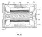
- FIG. 2Ais a cross-sectional view of an example rotor.
- FIG. 2Cshows an example rotor with a composite sleeve formed by a metallic tape wrapped around an outer jacket of the rotor.
- FIG. 2Dis a detail cross-sectional view of an end of an example rotor having a rotor sleeve formed from a metal alloy tape.
- FIG. 2Eis a detail cut-away view of an example rotor sleeve.
- FIG. 2Fis a detail cross-sectional view of another example rotor.
- FIG. 2Gis a detail, perspective view of the example rotor of FIG. 2E .
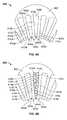
- FIGS. 2H-2Pare schematic cross-sectional views of different example rotors having segmented magnets, wherein the arrows associated with each magnet segment represent the respective magnet segment's north pole orientation.
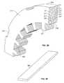
- FIG. 2Qis a side view of an example rotor showing a plurality of flow path channels formed by segments of the rotor magnets.
- FIG. 2Ris a side view of another example rotor having grooves formed in the rotor to facilitate introduction of a filler material thereinto.
- FIG. 2Sis a side view of another example rotor having an annular channel 264 formed therein along with an inlet formed in a end ring thereof.
- FIG. 2Tis a cross-sectional view of a magnet segment or magnet segment row having uniform radial magnetization.
- FIG. 2Uis a cross-sectional view of a magnet segment or magnet segment row having true radial magnetization.
- FIG. 3Ashows a cross-sectional view of an example electric machine.
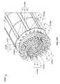
- FIG. 3Bshows a perspective view of an example stator core for use in an electric machine.
- FIG. 3Cshows two adjacent yoke portions formed, each yoke portion formed from a plurality of individual portions.
- FIG. 3Dshows an example portion used to form part of the yoke portions of FIG. 3C .
- FIG. 3Eshows an example stator bar of the example stator of FIG. 3B used to provide alignment and rigidity to the stator.
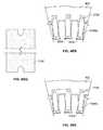
- FIG. 3Fis an example end plate of the example stator of FIG. 3B .
- FIG. 3Gis a partial detail view of an end of the example stator of FIG. 3B .
- FIG. 3Hshows an example stator tooth lamination for use in the example stator of FIG. 3B .
- FIG. 3Ishows a side view of two adjacent stator tooth laminations having respective protrusions and receptacles for aligning and/or attaching the stator tooth laminations.
- FIG. 3Jshows an alternate configuration for aligning and/or attaching adjacent stator tooth laminations.
- FIG. 3Kis a schematic view of tooth segments disposed in a channel formed in adjacent yokes.
- FIG. 3Lis a cross-sectional view of an example electric machine having a protective barrier around the stator.
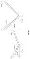
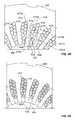
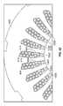
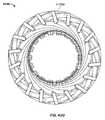
- FIG. 4Ais a partial schematic end view of an example core of a stator for an electric machine.
- FIG. 4Bis a partial schematic end view of an example core of a stator for an electric machine.
- FIG. 4Dis a partial schematic end view of an example core of a stator for an electric machine.
- FIG. 4Eis a partial schematic end view of an example core of a stator for an electric machine.
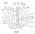
- FIG. 4Fis a schematic end view of example end turns of a stator for an electric machine.
- FIG. 4His a schematic side view of example end turns of a stator for an electric machine.
- FIG. 4Jis a schematic cross-sectional view of an example stator for an electric machine.
- FIG. 4Mis a schematic of example end turns.
- FIG. 4Pis a schematic side view of example end turns of a stator for an electric machine.
- FIG. 4Qis a schematic perspective view of example end turns of a stator for an electric machine.
- FIG. 4Ris a partial schematic cross-sectional view of an example core of a stator for an electric machine.
- FIG. 4Sis a partial schematic cross-sectional view of an example core of a stator for an electric machine.
- FIG. 4Tis a partial schematic cross-sectional view of an example core of a stator for an electric machine.
- FIG. 4Uis a partial schematic cross-sectional view of an example core of a stator for an electric machine.
- FIG. 4Vis a perspective view of an example wedge for insertion into one or more stator core slots.
- FIG. 4Wis a wiring diagram showing connections for one phase of a three phase electric machine.
- FIG. 4Xis a wiring diagram showing connections for one phase of a three phase electric machine.
- FIG. 4Yis a wiring diagram showing connections for one phase of a three phase electric machine.
- FIG. 4Zis a partial schematic end view of an example core of a stator for an electric machine.
- FIG. 4 AAis a partial schematic end view of an example core of a stator for an electric machine.
- FIG. 4 BBis a partial schematic end view of an example core of a stator for an electric machine.
- FIG. 4 CCis a partial schematic end view of an example core of a stator for an electric machine.
- FIG. 4 DDis a partial schematic end view of an example core of a stator for an electric machine.
- FIG. 4 EEis a schematic end view of example end turns of a stator for an electric machine.
- FIG. 4 FFis a schematic end view of example end turns of a stator for an electric machine.
- FIG. 4 GGis a schematic end view of example end turns of a stator for an electric machine.
- FIG. 4 HHis a schematic side view of example end turns of a stator for an electric machine.
- FIG. 4 IIis a schematic cross-sectional view of an example stator for an electric machine.
- FIG. 4 JJis a schematic cross-sectional view of an example stator core for an electric machine.
- FIG. 4 KKis a schematic cross-sectional view of an example stator core for an electric machine.
- FIG. 4 MMis a perspective view of an example wedge for insertion into one or more stator core slots.
- FIG. 4 NNis a schematic end view of an example stator core for an electric machine.
- FIG. 4 OOis a perspective view of an example wedge for insertion into one or more stator core slots.
- FIG. 4 PPis a schematic end view of an example stator core for an electric machine.
- FIG. 4 QQis an example slot liner for a stator slot of an electric machine.
- FIG. 4 RRis an end view of an example stator core for an electric machine showing the slot liner of FIG. 4 QQ residing in the slot and retained by a liner clamp.
- FIG. 4 SSis an end view of an example stator core for an electric machine showing the slot liner of FIG. 4 QQ residing in the slot and retained by an alternate liner clamp.
- FIG. 4 TTis a partial perspective view of an example stator for an electric machine.
- FIG. 4 UUis an end view of an example stator for an electric machine.
- FIG. 4 VVis a partial perspective view of an example stator for an electric machine.
- FIG. 4 WWis a partial side view of an example stator for an electric machine.
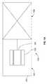
- an electric machine system 100includes an electric machine 102 coupled to a companion device 104 .
- the electric machine 102can operate as a generator, producing electrical power from mechanical movement, operate as a motor producing mechanical movement from electricity, or alternate between generating electrical power and motoring.
- a prime moversupplies mechanical movement to the electric machine 102
- the electric machine 102converts the mechanical movement into electrical power.
- the companion device 104may be the prime mover.
- the mechanical movement output from the electric machine 102can drive another device.
- the electric machine 102can drive the companion device 104 .
- the electric machine 102includes a stationary member and a movable member that, by interaction of magnetic fields, generates electrical power as the movable member moves relative to the stationary member and/or moves the movable member as electrical power is applied to the stationary member.
- the electric machine 102is described as a rotating electric machine, where the movable member is a rotor 106 supported to rotate in the stationary member, a stator 108 .
- Rotor 106is coupled to the companion device 104 to drive the companion device 104 and/or be driven by the companion device 104 . While FIG.
- the electric machine 102is an alternating current (AC), synchronous, permanent magnet (PM) electric machine having a rotor 106 that includes permanent magnets and stator 108 that includes a plurality of formed or cable windings about a core.
- the electric machinecan be an other type of electric machine, such as an AC, asynchronous, induction machine where both the rotor and the stator include windings or another type of electric machine.
- the electric machine 102is carried by and contained within a housing 110 .
- the housing 110can be wholly separate from the companion device 104 , separate from and coupled to the companion device 104 , or partially or wholly shared with the companion device 104 (i.e., the electric machine 102 and companion device 104 carried by and contained within a common housing).
- the electric machine system 100may be a subsea electric machine configured for subsea operation, submerged in the open sea (i.e., outside of a well or a pipeline).
- the housing 110is a pressure vessel sealed against passage of fluid between the interior of the housing 110 and the surrounding environment (e.g., the surrounding seawater).
- the housing 110is constructed to withstand the ambient pressures about the electric machine system 100 and thermal loads exerted by the surrounding environment, as well as pressures and thermal loads incurred in operating the electric machine 102 and companion device 104 .
- the housing 110may be constructed of a material that resists corrosion, for example, stainless steel, nickel alloys such as Inconel a registered trademark of Special Metals Corporation, and/or other materials.
- the housing 110may additionally or alternatively be plated or coated with a material that resists corrosion, for example, Inconel, epoxy, polyetheretherketone, ethylene chlorotrifluoroethylene and/or other materials.
- the housing 110may carry anodes (not shown) to assist in resisting corrosion.
- the housing 110may be coupled to a skid or other structure that aligns with and engages (e.g., by way of guide tubes that receive guide cones) other subsea structures.
- the companion device 104can include a number of different possible devices.
- the prime movermay include one or more of a fluid motor operable to convert fluid (gas/liquid) flow into mechanical energy, a gas turbine system operable to combust an air/fuel mixture and convert the energy from combustion into mechanical energy, an internal combustion engine, and/or other type of prime mover.
- the companion device 104is driven by the electric machine 102
- the companion devicecan include a number of different possible devices.
- the companion device 104can include one or more of a rotating and/or reciprocating pump, rotating and/or reciprocating compressor, mixing device, or other device.
- pumpsinclude centrifugal pump, axial pump, rotary vane pump, gear pump, screw pump, lobe pump, progressive cavity pump, reciprocating positive displacement or plunger pump, diaphragm pump, and/or other types of pumps.
- compressorsinclude centrifugal compressor, axial compressor, rotary vane compressor, screw compressor, reciprocating positive displacement compressor and/or other types of compressors.
- the electric machine 102can be coupled to two or more companion devices 104 at the same time.
- the electric machine 102can also be coupled to two or more companion devices 104 (to drive and/or be driven by the devices 104 ).
- one or more companion devices 104can be provided at each end of the electric machine 102 .
- a configuration with two companion devices 104can have one provided at one end of the electric machine 102 , and another coupled to the first companion device.
- multiple companion devices 104are provided, they need not all be of the same type of companion device.
- FIG. 1Bdepicts an example electric machine system 100 a where the companion device 104 a is a pump driven by the electric machine 102 a .
- One pump companion device 104 ais shown. In other instances, more pump companion devices 104 a can be provided. For example, two pump companion devices 104 a could be provided on opposing ends of the electric machine 102 a (e.g., in a configuration similar to the compressor companion devices 104 b shown below). In certain instances, two or more pump companion devices 104 a could be provided on the same side of the electric machine 102 a .
- the example electric machine system 100 ais configured for subsea operation, submerged in the open sea (i.e., outside of a well). In other words, the example electric machine system 100 a is a subsea pump system.
- the housing 110 ais a pressure vessel sealed against passage of fluid between the interior of the housing 110 a and the surrounding environment (e.g., the surrounding seawater).
- the housingis flooded with a heat transfer fluid that is communicated to both the rotor 106 and the stator 108 .
- the heat transfer fluidincludes a liquid, is primarily a liquid and/or is entirely liquid.
- the heat transfer fluidcan include water, mono-ethylene glycol (MEG), mono-propylene glycol (MPG), an oil, a fluid similar to or the same as that being pumped by the pump companion device 104 a , and/or other fluid.
- the pressure of the heat transfer fluidis above the ambient pressure about the exterior of the electric machine system 100 a by an amount substantially greater than the incidental pressure incurred in circulating the heat transfer fluids through the electric machine system 100 a .
- the housing 110 ahas a flange 112 proximate the drive end of the electric machine 102 a .
- Flange 112is configured to be sealingly joined, by bolts and/or otherwise, to the companion device 104 a , for example, at a corresponding flange 124 of the companion device 104 a .
- a seale.g., ring gasket, o-ring and/or other
- the subsea pump systemcan be of an integrated configuration where the electric machine and companion device have a common housing and/or common shaft.
- the housing body that surrounds both the electric machine and the companion devicecan be a unitary piece (i.e., not readily separable, such as by removal of fasteners).
- the rotor of the electric machinecan be unitary with the drive shaft of the companion device (i.e., not readily separable, such as by removal of fasteners or by release of the drive coupling).
- subsea pump systemcan be of a non-integrated configuration having the housing of electric machine 102 a wholly separate (not coupled and/or substantially coupled) from the housing of the pump companion device 104 a.
- the stator 108is generally cylindrical and the outer diameter thereof is closely received in the inner diameter of the housing 110 a to support the stator 108 relative to the housing 110 a .
- the outer diameter of the stator 108may be keyed (using a protruding male key received in a female receptacle), bolted and/or otherwise secured to the inner diameter of the housing 110 a to rotationally affix the stator 108 relative to the housing 110 a .
- the stator 108is axially retained with end rings 126 that are bolted and/or otherwise affixed to the housing 110 a .
- the external heat exchanger 132could additionally or alternatively receive and cool process fluids being acted upon by the companion device. Additionally, as described below the heat transfer fluid in the housing 110 a and the process fluids can be one in the same. In certain instances, the heat exchanger 132 could be used for cooling fluids from within the housing 110 a and an additional external heat exchanger (not shown) can be provided about the housing 110 a to receive and cool process fluids being acted upon by the companion device.
- FIG. 1Bdepicts a multistage centrifugal pump. Eight centrifugal impellers 140 a are depicted arranged on central drive shaft 142 a of the pump companion device 104 a . In other instances fewer or more impellers can be provided.
- the drive shaft 142 ais shown coupled to the drive stub 117 a of rotor 106 by a drive coupling 144 .
- drive coupling 144is shown as having two female ends that internally receive male ends of the drive stub 117 a and drive shaft 142 a , in other instances the drive coupling 144 can be a male coupling received into female receptacles provided in the drive stub 117 a and the drive shaft 142 a .
- the manner of coupling the drive stub 117 a and the drive shaft 142 acan include a combination of both male and female drive coupling configurations and/or other configurations.
- the drive shaft 142 acould be integral with the rotor 106 (i.e., constructed as unitary part with the rotor 106 , having no coupling, gear box, screw thread or other mechanical connection).
- the drive shaft 142 ais supported on bearings 122 carried in a pump body 146 a secured to the companion machine housing 148 .
- the bearings 122can be a number of different possible types of bearings, and the number and types of bearings can be different at different locations along the drive shaft 142 a .
- the bearings 122can include one or more of journal bearings (e.g., a tilt-pad journal bearing and/or other type), magnetic bearings, hybrid magnetic bearings, ball bearings and/or other types of bearing.
- One or more of the bearings 122is a thrust bearing (e.g., a tilt-pad thrust pad and/or other type).
- drive end of the drive shaft 142 aincludes at least one axial or thrust bearing to axially retain the drive shaft 142 a relative to the pump body 146 a and at least one radial bearing to provide radial support to the drive shaft 142 a relative to the companion machine housing 148
- the non-drive end of the drive shaft 142 aincludes at least one radial bearing to provide radial support to the drive shaft 142 a relative to the companion machine housing 148
- a seal 120may be provided about the drive shaft 142 a to seal or substantially seal against flow of fluids from the centrifugal impellers 140 a towards the electric machine 102 a.
- three phase AC electric currentis provided to the stator 108 of the electric machine 102 a via the penetrators 128 .
- the electrical currentenergizes windings of the stator 108 , and causes the rotor 106 to rotate.
- Rotating the rotor 106drives the drive shaft 142 a of the pump companion device 104 a and pumps process fluid from the inlet 150 to the outlet 152 .
- FIG. 1Cshows the system 100 b configured for a cartridge type installation/removal of the electric machine 102 .
- all or a majority of the electric machine 102including the stator 108 and the rotor 106 , is carried in an intermediate housing 115 that is received by the housing 110 b .
- the intermediate housing 115 carrying electric machine 102 componentscan be installed into or removed from the main housing 110 b as a unit or cartridge.
- the cartridge type installation/removalsimplifies service or replacement of the electric machine 102 , because the electric machine 102 need not be assembled/disassembled piece by piece into the main housing 110 b .
- the electric machine 102can be assembled into the intermediate housing 115 and tested prior to installation into the main housing 110 b.
- the interior of the housing 110 bis in communication with the process fluids on which the compressor companion devices 104 b are operating.
- the process fluidsare under pressure, because they have been compressed by the compressor companion devices 104 b .
- the process fluidsare above the ambient pressure about the exterior of the electric machine system 100 b by an amount substantially greater than the incidental pressure incurred in circulating the process fluids through the electric machine system 100 b .
- communicationis established by omitting a seal or providing an imperfect seal about the drive shaft 142 b of the compressor companion device 104 b and/or providing other fluid communication paths from the compressor companion device 104 b .
- the end plates 116 b , 118 bmay be additionally provided with ports 154 to facilitate communication of process fluids into the gap between the rotor 106 and stator 108 .
- the electric machine 102 bmay also be provided without an integrated fluid circulation pump 130 .
- the fluids used in operation of the electric machinecan contain constituents that may be corrosive, reactive and/or otherwise harmful to one or more of the components of the electric machine 102 b .
- the rotor 106 and stator 108may be fortified against exposure to the process fluids.
- the rotor 106 and/or stator 108may be sealed against exposure to the process fluids and/or coated with protective coatings.
- FIG. 1Cdepicts multistage centrifugal compressors. Eight centrifugal impellers 140 b are depicted arranged on central drive shaft 142 b of the compressor companion device 104 b . In other instances fewer or more impellers can be provided.
- the drive shaft 142 bis shown coupled to the drive end of rotor 106 by a drive coupling 144 . In other instances, the drive shaft 142 b could be integral with the rotor 106 (i.e., constructed as unitary part with the rotor 106 , having no coupling, gear box, screw thread or other mechanical connection).
- FIG. 1Cdepicts an electric machine system 100 b incorporating magnetic bearings 122 .
- one end of the rotor 106may be supported by an axial and radial magnetic bearing 122 carried in the end plate 118 b and the other end of the rotor 106 supported by a radial magnetic bearing 122 carried in end plate 116 b .
- Additional conventional bearingsfor example cartridge ball bearings and/or another type, may be provided to provide secondary and/or contingency support the rotor 106 .
- the companion devices 104 bcan also be provided with magnetic bearings 122 carried in the compressor body 146 b.
- three phase AC electric currentis provided to the stator 108 of the electric machine 102 b via the penetrators.
- the electric currentenergizes windings of the stator 108 , and causes the rotor 106 to rotate.
- Rotating the rotor 106drives the drive shaft 142 b of the compressor companion devices 104 b and compresses process fluid from the inlet 150 to the outlet 152 .
- a portion of the process fluidsis communicated with the interior of housing 110 b , causing process fluid to circulate over the stator 108 and through the gap between the stator 108 and the rotor 106 .
- An additional flow of fluidmay be provided through the heat exchanger 132 to be cooled as it passes through the helical coil of the heat exchanger 132 .
- the rotor hub 202is adapted to support permanent magnets 204 positioned so as to magnetically interact with a stator provided in the electric machine system.
- the magnets 204can be bonded or otherwise connected to the rotor hub 202 .
- High energy permanent magnets 204can be used, for example neodymium-iron-boron based, or samarium-cobalt based magnets. In certain instances, the permanent magnets 204 are bonded to the rotor hub 202 .
- a rotor shaft 206can be provided, forming a rotational axis of the rotor 200 .
- the rotor shaft 206extends axially from both ends of the rotor hub 202 .
- the rotor shaft 206may be constructed as a single piece or modularly from a plurality of shaft segments. In certain instances, the rotor shaft 206 can be hollow, including the rotor hub, to promote rotor cooling or to facilitate flow of fluid through the electric machine.
- the rotor 200can further include one or more cooling passages 217 through the interior thereof to communicate fluid through the interior of the rotor. In FIG. 2A , a central passage 217 through center of rotor, entering on circumferential surface of the rotor hub 202 , is shown.
- a rotor sleeve 212can serve to enclose the outer surface of the entire rotor 200 or portions of the rotor 200 , such as the rotor hub 202 and magnets 204 .
- the rotor sleeve 212can be manufactured from material that allows the sleeve to protect rotor components as well as provide structural support to rotor components, such as the rotor hub 202 .
- the rotor sleeve 212can be constructed from a fiber reinforced composite, such as a carbon fiber composite, aramid fiber composite (e.g., Kevlar a registered trademark of I.E.
- a sleeve covering 212can serve to provide radial support for the rotor hub 202 and magnets 204 positioned thereon, preventing loosening or detachment of magnets 204 from the rotor hub 202 during operation of the rotor 200 at high rotational speeds.
- the sleeve 212can also serve to insulate the rotor 200 and rotor components from outside elements.
- the sleeve 212can be adapted to be air- or water-tight, in order to seal the rotor components.
- the electric machine system in which the rotor 200 is disposedmay contain heat transfer fluid, process fluids, and/or other fluids harmful to the rotor 200 .
- the sleeve 212may cover and isolate those portions of the rotor 200 sensitive to corrosion or otherwise adverse to contact with the fluid.
- the rotor 200may incorporate rotor elements and techniques for mounting the rotor sleeve 212 to the rotor 200 so as to seal at least the rotor hub 202 .
- rotor 200can include end rings 214 positioned at one or both ends of the rotor hub 202 and mounted coaxially on the rotor shaft 206 .
- the end ring 214is bonded or otherwise attached to the rotor 200 so that the inner surface of the end ring 214 abuts the end of the rotor hub 202 , extending radially so as to provide axial support to magnets 204 positioned on the rotor hub 202 .
- the end rings 214are positioned at each end of the rotor hub 202 .
- the end ring 214can be of metallic material (e.g., Inconel, MP35N and/or other material). In certain instances, the material can be selected for its ferromagnetic properties as well, so as to enhance or avoid interference with the electromagnetic function of the magnetic rotor hub 202 . Additionally, certain instances of the end ring 214 may be constructed so as to make the end ring corrosion-resistant, for example, through galvanization or anodization of the end ring material. In other instances, the end rings 214 can be built into or integrated into the rotor hub 202 itself. For example, a rotor hub 202 may be provided with an inset for mounting the magnets, resulting in the end sections of the hub having a larger diameter than the inset.
- a ledge 217can be provided circumferentially on the outside diameter of the end ring 214 .
- the ledge 217serves as a landing platform for the positioning of an end treatment strip 220 around the outside diameter of the end ring 214 , the end treatment strip 220 forming a cylinder or a hoop.
- the outer diameter of the thin end treatment strip 220is equal or approximately equal to the diameter of the rotor hub 202 , including the magnets 204 mounted thereon.
- the end treatment strip 220can be a composite material capable of bonding to the sleeve 212 .
- the end treatment strip 220 and sleeve 212are constructed from similar materials, such as pre-impregnated carbon fiber or other material.
- a circumferential groove 221can also be provided on the ledge 217 of the end ring 214 , in order to provide for a seal 222 (e.g., an o-ring, gasket and/or other seal) to be positioned on the ledge surface 217 .
- the seal 222seals or substantially seals between the end ring 214 and the end treatment strip 220 wrapped around the end ring's ledge 217 .
- the circumferential groove 221can be machined onto the end rings 214 before and/or after the end rings 214 are installed to the rotor 200 (as discussed below).
- the sleeve 212can be sealed to the rotor 200 by sliding and/or threading the end rings 214 onto the shaft 206 so as to abut the ends of the rotor hub 202 .
- a seale.g., o-ring, gasket and/or other seal
- sealante.g. thread sealant, sealant applied to the juncture between the shaft 206 and end rings 214 , and/or other sealant
- the seal 222can be positioned in the end ring 214 before or after positioning and connecting the end ring 214 to the shaft 206 .
- the respective threads of the end rings 214can be oriented so that the end rings 214 are tightened to the shaft 206 when the rotor 200 is rotated in normal operation.
- the end rings 214can additionally be affixed to the rotor hub 202 with an adhesive.
- the end treatment strip 220After rigidly connecting the end ring 214 to the shaft 206 (e.g., by threading, welding and/or otherwise), the end treatment strip 220 is positioned on the outside diameter of the end ring 214 on the ledge 217 .
- the end treatment strip 220may then be wound onto the ledge 217 , to position the strip 220 on the end ring 214 , or may simply be slipped over the end ring 214 into position on the ledge 217 . With the end rings 214 , seals 222 , and end treatment strips 220 in place, the construction of the sleeve 212 can be completed.
- Winding or otherwise securely wrapping the sleeve 212 onto the rotor hub 202 and on top of the end treatment strip 220can press the end treatment strip 220 radially down onto the ledge surface 217 , causing the strip 220 to shrink tightly onto the end ring 214 .
- This pressurecompresses the seal 222 into the groove 221 to form a seal between the strip 220 and the end ring 214 .
- the sleeve 212is wound onto the rotor 200 the sleeve 212 is bonded to the strip 220 .
- This bondingextends the seal between the strip 220 and end ring 214 to the sleeve 212 , thereby sealing the rotor hub 202 covered by sleeve 212 .
- clampsmay be employed to secure the strip 220 to the end ring 214 while the sleeve is wrapped to the rotor 200 and bonded to the strip 220 .
- the bonding of the strip 220 to the sleeve 212can occur at an elevated temperature, to allow for a bond that will be less temperature sensitive.
- the end treatment strips 220 , the seal 222 , and seal grove 221may be omitted.
- the sleevemay be securely wound onto the rotor hub 202 and the circumferential surfaces of the end rings 214 .
- the sleeve 212may be fabricated from carbon fiber impregnated with thermoplastic material such as polyetheretherketone (PEEK). Thermoplastic material, such as PEEK, may also be applied to or pre-coated on the outer diameter of the end rings 214 prior to having the sleeve 212 wound on the hub assembly.
- pre-coated end rings 214may be provided with sufficient material so that a coating formed from PEEK (or other material), for example, remains on the end rings 214 following grinding and before the sleeve 212 is wound over both the end rings 214 and rotor hub assembly.
- PEEKor other material
- heat or pressuremay be applied to bond the sleeve to the end ring, forming a seal with the PEEK at each end of the sleeve 212 , thereby isolating the rotor hub, magnet segments, and other components covered by the sleeve from contact with potentially hazardous external fluids and/or other materials.
- secondary end rings 215may be slid and/or threaded onto the shaft 206 so as to abut the end rings 214 .
- the secondary end rings 215have a diameter substantially equal to the sleeve 212 diameter, and serve to protect the outer surface of the sleeve 212 and/or to provide a location for rotor balancing (either by material removal or addition).
- a seale.g., o-ring, gasket and/or other seal
- sealante.g.
- thread sealantsealant applied to the juncture between the shaft 206 and secondary end rings 215 , and/or other sealant
- the juncture between the secondary end rings 215 and the end rings 214can be filed with resin and/or adhesive (thus, adhering the secondary end rings 215 to the end rings 214 and filling).
- the respective threads of the secondary end rings 215can be oriented so that the secondary end rings 215 are tightened to the shaft 206 when the rotor 200 is rotated in normal operation.
- the outward facing edges of the secondary end rings 215can be rounded or the rings' outer surface may be conical (with the smaller diameter facing outward) to facilitate fluid flow over the secondary end rings 215 .
- tubular bandsconstructed of material more resistant to wear and other damage than the composite sleeve 212 (e.g., non-magnetic metal, ceramic, polymer and/or other material), may be positioned at each end of the rotor hub, concentrically atop the sleeve 212 . Consequently, the tubular bands may cover the ends of the sleeve, thereby protecting the ends of the sleeve from erosion, abrasion, or other damage that may occur during operation of the rotor 200 .
- a tubular bandmay be replaced with a thin, non-magnetic, metal alloy tape 223 (e.g., nickel alloy (e.g., Inconel), non-magnetic stainless steel, titanium and/or other metal) wrapped around the outer surface of the rotor sleeve 212 and bonded to end rings (not shown) positioned on the rotor shaft 206 to form a sleeve 229 .
- the metalcan be corrosion resistant.
- a insulating coating and/or surface treatmentmay be applied to the tape 223 to inhibit currents from circulating between adjacent laps of the tape 223 .
- coating and/or surface treatmentinclude oxidation, anodization, phosphate/chromate/silicate coating (e.g., American Society for Testing and Materials (ASTM) A976 C-4 and/or C-5) and/or other coatings.
- the sleeve 229may extend axially beyond the edges of the rotor sleeve 212 .
- a first end of a piece of tape 223may be bonded to an end ring adjacent to a first sleeve end 225 .
- the tape 223may be bonded to the end ring using a laser weld, resistance weld, TIG weld, chemical bond, or any bonding method.
- the tape 223may be wound on top of the rotor sleeve with adequate tension so as to cover the sleeve ends and maintain positive pressure between the tape 223 and the rotor sleeve 212 in all operating conditions of the rotor 200 .
- the resulting tape winding 223may be laid in butt laps across the outer surface of the rotor sleeve, resulting in a smooth surface that minimizes the thickness of the tape wrapping 223 .
- Thin alloy tape wrappings 223may, among other advantages, minimize parasitic mass as well as parasitic currents appearing in the metallic tape as a result of the magnetic field of the rotor 200 or corresponding electric machine.
- Other implementationsmay employ other winding techniques as well as various tape material for reinforcing and protecting the rotor sleeve.
- the second end of the piece of tape 223may be bonded to the opposite end ring. In some instances, for example in a butt lap winding, excess tape may result at the edges of end rings. The excess tape may be trimmed flush with the end ring faces to complete the tape winding 223 .
- FIG. 2Eis a detailed cut-away cross-sectional view of an example sleeve 212 .
- the sleeve 212can be manufactured or constructed of any material possessing the structural, resistive, and/or chemical properties desired for the particular rotor implementation, for example a fiber-reinforced composite.
- the sleeve 212can serve a number of functions.
- the sleeve 212can be constructed of composite material capable of providing structural support and corrosion protection for the rotor hub, as well as sealing the rotor hub from exposure to foreign elements. Heating of the rotor 200 can result in thermal expansion of one or more of the rotor elements or sleeve.
- a fiber-reinforced composite sleeve materialsuch as carbon fiber
- the sleevemay be multi-layered.
- FIG. 2Eshows a multi-layer fiber-reinforced composite sleeve wrapping 212 .
- the top layer 224(or, in certain instances, layers) are cosmetic layers. These layers may possess functional characteristics as well. For example, to achieve strength and rigidity as well as control differential thermal expansion in one or multiple directions, the layers can have fibers oriented predominantly or all in the same direction (e.g. maximum strength in one direction) or different orientations (strength in multiple directions).
- intermediate layer 226can be a first, primarily axially-oriented carbon fiber composite layer layered beneath the cosmetic layer 224 (i.e., nearer to the outer circumferential surface of rotor 200 ).
- the layer 226can be made of pre-impregnated carbon fiber composite sheet capable of providing very strong axial support as well as provide corrosion and leakage protection.
- Layer 228positioned beneath layer 226 , can be one or more carbon fiber composite layers with primarily circumferentially-oriented pre-impregnated carbon fiber tape. Layers with circumferentially-oriented carbon fiber, such as layer 228 , do not provide substantial axial strength, instead providing circumferential strength.
- Layer 230can be wrapped so as to directly contact the rotor 200 , rotor hub 202 , rotor hub magnets 204 , and/or end rings 214 , covering all or a portion of the rotor 200 .
- additional layerscan be provided between layer 230 and the rotor 200 .
- Additional layersmay also be provided between layers 224 , 226 , 228 , and 230 . Indeed, certain instances may make use of repeated layering of layers 224 , 226 , 228 , 230 in similar or different orientations and orders.
- the orientations of one or more of the layers 224 , 226 , 228 , 230could be oriented in non-axial and/or non-circumferential directions.
- one or more of the layers 224 , 226 , 228 , 230could be oriented at 45 degrees, 30 degrees and/or another angle relative to the axial direction.
- fibers in a fiber-reinforced compositeneed not be oriented in the same direction.
- fiber-reinforced compositescan be selected for the axial and circumferential support that have fibers primarily in one of the axial or circumferential direction.
- the layerin such an instance, can have a greater density of fibers oriented on one orientation or dimension, than in another dimension.
- the material forming the layers of a multi-layered sleeve 212need not be uniform.
- the one or more layer materialsmay be selected so as to minimize stress on the rotor hub 202 , magnets 204 , as well as the surrounding sleeve 212 due to thermal expansion during operation.
- One technique for minimizing these stressesis to build the sleeve 212 so that the sleeve 212 expands axially with the interior rotor components at the rotor's 200 operating temperature.
- rotor 200 , rotor components, and sleeve layersexpand according to the coefficient of thermal expansion (CTE) of materials used in the rotor and sleeve.
- CTEcoefficient of thermal expansion
- rotor sleeve 212 materialscan be selected and/or engineered to have CTEs similar to the CTEs of the portion of the rotor 200 or rotor elements to be covered by the rotor sleeve 212 .
- the fiber and/or resin employed to form the rotor sleevecan be selected so as to result in a composite sleeve material with a CTE equal or substantially equal to, complimenting, or otherwise matched to the CTE of the rotor shaft 206 , rotor hub 202 , and/or magnet 204 material.
- Matching CTEcan, among other benefits, allow the sleeve 212 to expand with the expansion of the rotor components wrapped in the sleeve 212 .
- the density of fibers used in a fiber-reinforced sleevecan also be adjusted so as to engineer the net CTE of the sleeve or sleeve layer.
- one or more layersincluding axially oriented, circumferentially oriented and/or other oriented layers, may be selected with varying CTEs so as to engineer a sleeve having a net CTE matched to the relevant portions of the rotor 200 to be covered by the sleeve 212 .
- non-CTE-matched sleeve layerscan be provided in addition to CTE-matched sleeve layers in the sleeve 212 .
- sleeve layers closest to the rotor hub 202 surfacemay be selected with CTE matched to the CTE of the rotor hub or rotor hub components, while outer sleeve layer material is selected based on other considerations, such as structural support, puncture resistance, or corrosion resistance.
- FIGS. 2F and 2Gillustrate another implementation of an example rotor sleeve 212 .
- FIG. 2Fshows a detailed cross-sectional view of a multi-layered rotor sleeve 212 .
- FIG. 2Gis a detailed perspective view of the sleeve shown in FIG. 2F .
- a set of outer layers 232 , 234can be provided in the sleeve 212 together with a set of segmented layers 236 , 238 , 239 , 240 .
- the outer layers 232 , 234can include one or more composite layers, including axially, circumferentially and/or otherwise oriented layers.
- the segmented layers 236 , 238 , 239 , 240are positioned to align with the circumferential segmentation of one or more of the magnets 204 a , 204 b , 204 c , 204 d so that each segmented layer is aligned with one or more circumferential rows of magnets.
- Thiscan allow for the expansion and contraction of each segmented layer 236 , 238 , 239 , 240 to be influenced by the thermal expansion and contraction of magnet row 204 a , 204 b , 204 c , 204 d positioned beneath it. While the example of FIGS.
- segmented layers 2F and 2Gshow segmented layers with axial widths corresponding to a single magnet row, segmented layers can correspond with and cover more than one row of magnet segments. Additionally, segmented layers 236 , 238 , 239 , 240 can be fiber-reinforced composite hoops having primarily circumferentially-oriented fiber, so as to provide structural support to the magnet segments positioned beneath the hoop layer. In some instances, magnet segments may be subject to greater thermal expansion and structural vulnerabilities (e.g., during rotation of the rotor at high speed), requiring additional radial support to limit these liabilities.
- the temperature at magnet 204 amay be higher than the temperature at magnet 204 c .
- the temperature differential between magnet rows 204 a and 204 ccan result in magnet 204 a experiencing thermal expansion larger than that experienced at magnet row 204 c .
- segmented layer 236 positioned in alignment with magnet row 204 amay expand more than segmented layer 239 positioned in alignment with magnet row 204 c .
- Gapsmay exist between the segmented layers 236 , 238 , 239 , 240 so that the expansion of one segmented row does not interfere with another segmented layer.
- expansion forces in layers 232 , 234may be focused at or near the corresponding hoop segment, including the gap between the affected hoop segments. For instance, in the above example, thermal expansion forces transmitted to layers 232 , 234 may be focused at the gap between adjacent hoop segments 236 and 238 ; 238 and 239 ; and 239 and 240 .
- a segmented layercan also be accomplished using a unitary sleeve layer.
- a sleeve layercan possess strength characteristics that vary across the length of the sleeve layer. Variation in sleeve layer strength can be aligned with elements, such as magnet segment rows, so that areas of highest strength are aligned with areas of the rotor requiring greatest reinforcement or more subject to differential thermal expansion.
- multiple layers of varying physical characteristicscould be grouped to form a sleeve with band-like strength sections, with gaps between the sections exhibiting strength or thermal expansion characteristics different than the sections themselves.
- One way this may be accomplishedis by fabricating sleeves with varied coefficients of thermal expansion (CTE).
- segmented layers 236 , 238 , 239 , 240 , or segmented hoops, aligned with magnet segment rows 204 a , 204 b , 204 c , 204 dmay be constructed of material with CTEs matched to the CTE of the magnet 204 a , 204 b , 204 c , 204 d positioned beneath it.
- FIGS. 2A , 2 F, and 2 Gshow examples of a rotor hub 202 with magnets 204 axially segmented (with segment boundaries formed in the circumferential plane along the axial body of the rotor hub 202 ), the magnets 204 can also be implemented as single member magnets, extending axially across the length of the hub body 202 . Additionally, magnets can be segmented circumferentially (with segment boundaries formed in a radial-axial plane) as shown in 2 E. Segmenting the magnets, however, can be advantageous as certain magnets may be more affordable and easier to implement as segmented pieces. Additionally, segmented magnets 204 can alter the electric and electromagnetic characteristics of the rotor and thereby be functionally desirable in some rotor applications.
- FIGS. 2H-2Pare cross-sectional views of example rotor hubs 202 .
- Magnets 204can be mounted directly to the outer surface of the rotor hub 202 and/or to the rotor hub 202 via intermediate materials, for example, to electrically insulate the magnets 204 from the rotor hub 202 , bond or improve bonding to the rotor hub 202 , and/or other reasons.
- the intermediate materialcan include an adhesive (e.g., an acrylic adhesive and/or other adhesives), electrically insulating tape, a solder material, a reactive nanofilm, and/or another material.
- an interstitial filler materialis applied to the rotor 200 to fill spaces between the magnets 204 and/or the rotor hub 202 .
- An example materialincludes stainless steel putty (e.g., stainless steel putty made by ITW Devcon) and/or other materials.
- the rotor 200prior to installation of the sleeve 212 , can be dipped in or flooded with an epoxy resin to ensure all the gaps between the magnets 204 , the rotor hub 202 , and/or the end rings 214 are filled and further protect against fluid ingression.
- interstitial filler materialmay be injected into the rotor hub assembly while providing a vacuum within the hub assembly.
- the magnets 204 and rotor hub 202may be enclosed in a disposable sleeve (e.g., a polymer bag and/or other sleeve), and the sleeve may be sealed at both ends of the rotor hub assembly.
- the vacuumis operable to remove the air and/or other gases (“gases”) within the sleeve, including gases residing in voids between the magnets 204 and/or the rotor hub 202 .
- thermosetting resinmay be introduced into the disposable sleeve to penetrate the empty spaces in the rotor hub assembly. Upon curing of the resin, the disposable sleeve may be removed. Thereafter, manufacture of the rotor may be resumed, including wrapping a protective rotor sleeve 212 around the rotor hub assembly.
- the rotor sleeve 212itself may be used in lieu of the disposable sleeve of the previous example.
- Pluggable inletsmay be provided on each of the end rings 214 , allowing a vacuum pump to be connected to one end of the hub assembly and a high pressure pump to be connected to the other end.
- the vacuum pumpvacates air from the hub assembly, sealed by the sleeve 212 .
- the high pressure pumpmay inject the resin into voids in the hub assembly.
- the end ring inletsmay be plugged and the resin cured to seal the hub assembly interior. Subsequent manufacturing operations may then be performed.
- the hub and/or the magnet segmentsmay be provided with flow path channels to guide filler material into voids between the hub 202 and the magnet segments 204 .
- FIGS. 2Q-2Rillustrate examples of such features.
- FIG. 2Qshows a rotor hub assembly 201 including a rotor hub 202 with a plurality of magnet segments 204 mounted on the hub 202 .
- the magnet segments 204are each formed to take a geometry that results in flow path channels 258 being formed when the magnet segments 204 are mounted to the hub 202 .
- channels 258may be aligned with those areas of the hub 202 and magnet segments 204 where voids are likely to appear, such as areas between adjacent magnet segments 204 .
- additional grooves 260may be provided on the hub 202 , in lieu of or in addition to the geometry of the magnet segments 204 , to provide the flow paths 258 .
- the end rings of the assemblymay also be used to guide the flow of filler material.
- an interior face of an end ring 214to be set adjacent to the rotor hub, can be provided with an annular channel 262 operable to direct filler material around the rotor hub assembly and into voids or other flow path channels positioned around the rotor hub.
- an inlet 264 in communication with the channel 262may be provided on the end ring 214 . The inlet 264 may be used to couple one or more vacuum pumps or injection pumps to the end ring 214 to deliver and direct filler material into voids within the hub assembly.
- the magnets' dimensions and orientation on the rotor hub 202may serve to form substantially a cylinder of magnet segments around the hub 202 .
- outer surfaces of the magnet segmentsmay require grinding once the magnetic segments are mounted to the hub 202 . Grinding the outer surfaces of the magnetic segments may be used to form the rotor hub 202 into a substantially uniform cylindrical outer surface.
- individual magnet segments 204 a - tcan vary in magnetic field orientation and magnitude as well as weight in order to achieve the desired electromagnetic, rotational and inertial rotor hub 202 profile.
- FIG. 2Hillustrates a cross-sectional view of one example rotor hub magnet configuration.
- sixteen circumferentially segmented magnets 204 a - tare positioned around the circumference of the rotor hub 202 .
- the geometry of the individual magnet segments 204 a - t and the outer surface of the rotor hub 202allow for the magnet segments 204 a - t to be mounted directly to a rotor hub 202 . As shown in FIG.
- the outer surface of the rotor hub 202 in certain instancesmay not be perfectly round, for example, the portion of the rotor hub 202 where magnet segments 204 a - t are mounted may be a regular polygon with a number of equilateral sides equal to the number of magnet segments 204 a - t to be mounted on the hub 202 .
- FIG. 2Hshows the outer surface of the rotor hub 202 having sixteen flat surfaces, running the axial length of the rotor hub 202 , against which corresponding flat surfaces of the sixteen magnet segments 204 a - t abut.
- the flat surfaces on the rotor hub 202 and the magnet segments 204 a - tare normal to a radial line emanating from the center of the hub 202 .
- the magnetic field vector at any one point along a uniform magnetized magnet segmentis parallel to the magnetic field vector at any other point along the magnet segment, as illustrated in FIG. 2T .
- the magnetic field vector at the center of the magnet segmentis radial.
- the magnetic field vectorscan be normal to radial or arcuate having the same center as the rotor.
- a magnet segment 204 with a true radially-directed magnetic fieldpossesses a magnetic field with magnetic field direction vectors that are each radial.
- the magnetic field direction vectorscan be normal to the outer surface 268 of the magnet segment.
- the magnetic field direction vectorscan be configured to all be perpendicular to the mating flat surfaces of the magnet segment and rotor hub.
- the magnetic field direction vector at the center line of the magnetic segmentcan be configured to be perpendicular to the mating flat surfaces of the magnet segment and rotor hub.
- Interpole magnet segments 204 h , 204 tdisposed between the two poles are interpole magnet segments 204 h , 204 t .
- Interpole magnet segments 204 h , 204 tcan be provided to adjust the magnetic flux distribution of the rotor 200 , transitioning the magnetic field between the two poles.
- the interpole magnet segments 204 h , 204 tpossess geometries similar to the radial magnet segments 204 a - g , 204 j - s , the interpole magnet segments having magnetic fields directed normal to these radial fields, or tangent to circumference of the rotor 200 .
- the arrangement of permanent magnet segments on the rotor hub 202can result in a net magnetic pole center vector 270 for the rotor 200 .
- the magnetic pole centerhas a direction vector component centered on magnet segment 204 d , the geometric center of the rotor's north pole.
- the rotor illustrated in FIG. 2Hhas a regular pole center.
- the pole center 270 of the rotor 200 illustrated in FIG. 2Pis also regular.
- the pole center vector 270is aligned between magnet segments 204 b and 204 c , this interface representing the geometric center of the top pole in rotor 200 .
- FIG. 2Killustrates an example of a rotor with an irregular pole center 270 .
- the geometric center of rotor 200 in FIG. 2Kis the arcuate midpoint of magnet segment 204 d .
- pole center 270 in FIG. 2Kis not aligned with the geometric center of the rotor.
- FIG. 2Iillustrates a cross-sectional view of another rotor magnet configuration.
- the structural dimensions of the rotor magnet configuration of FIG. 2Ican be substantially similar to the structural dimensions of the rotor magnet configuration of FIG. 2H .
- the configurations of FIGS. 2H and 2Ican have the same number of magnet segments, the magnet segments having substantially identical physical dimensions.
- FIG. 2Hillustrates an example two-pole rotor design
- FIG. 2Iillustrates an example four-pole design.
- 2Iincludes magnet segments 204 a , 204 b , 204 c
- the second poleincludes magnet segments 204 e , 204 f , 204 g
- the fourth polewith 204 p , 204 q , 204 s .
- At least one interpole magnet segment 204 d , 204 h , 204 n , 204 tcan be provided for each pole in the configuration, the interpole magnet segments 204 d , 204 h , 204 n , 204 t positioned between two adjacent poles.
- Interpole magnet segments 204 d , 204 h , 204 n , 204 tcan have magnetic fields directed approximately normal to the radial fields of the remaining magnet segments. In certain instances, half of the interpole magnet segments 204 h , 204 t can have magnetic fields directed in the clockwise direction, the other interpole magnet segments 204 d , 204 n can have fields directed in the counter-clockwise directions.
- a substitute for the two-pole rotor illustrated in FIG. 2Hcan be achieved using only four circumferential magnet segments mounted to the rotor hub 202 , as illustrated in FIG. 2J .
- Two pole magnet segments 204 w , 204 ycan be employed for the north and south poles of the rotor, with two, additional interpole magnet segments 204 x , 204 z disposed between the magnet segments 204 w , 204 y .
- the pole segments 204 w , 204 yare the primary magnetic segments for the rotor 200 , some implementations, including the example illustrated in FIG.
- FIG. 2Jmay provide for polar segments 204 w , 204 y with longer arcuate spans than the transitional interpole magnet segments 204 x , 204 z .
- the outer surfaces of the magnet segmentswhen mounted on the rotor hub 202 , can form a cylindrical outer surface of the rotor 200 , as also illustrated in the sixteen facet example of FIG. 2H .
- the four magnet segment rotor of FIG. 2Jhas two poles, as in FIG. 2H
- the FIG. 2J rotormay have a magnetic profile and performance characteristics distinct from those of the sixteen facet rotor of FIG. 2H .
- other configurations, employing the principles illustrated in the examples of the FIGS. 2H and 2Jare within the scope of the disclosure, allowing several facet-based design options tailored to the economics and performance considerations of the designer.
- FIG. 2Kis a cross-sectional view of yet another example two-pole magnet configuration.
- the two-pole magnet configuration example of FIG. 2Kcan employ interpole magnet segments 204 h , 204 t utilizing split-interpole construction.
- Each interpole magnet segment 204 h , 204 tcan be constructed of two separate magnet pieces 254 , 256 , bonded together to form a single magnet segment.
- Radial magnet segment piece 254can be a magnet with a radially-oriented magnetic field.
- Magnet segment piece 254 h belonging to interpole magnet segment 204 hcan have a radial magnetic field directed away from the center of the rotor hub 202 .
- Magnet segment piece 254 t belonging to interpole magnet segment 204 tcan then have a radial magnetic field directed toward the center of the rotor hub 202 .
- Normal magnet segment pieces 256 h , 256 tcan be bonded to radial magnet segment pieces 254 h , 254 t to form respective interpole magnet segments 204 h , 204 t .
- Normal magnet piece 256 h , bonded to radial magnet piece 254 hcan have a magnetic field directed normal to the radial magnetic field of piece 254 h , and oriented in a counter-clockwise direction.
- Normal magnet piece 256 tbonded to radial piece 254 t , can have a magnetic field normal to the radial direction, the field of normal piece 256 t oriented in the clockwise direction.
- Magnet pieces 254 , 256can be constructed of the same or dissimilar magnetic materials. Magnet pieces 254 , 256 can be equal sizes, or alternatively, one magnet piece can be larger than the other. Selecting the materials of the magnet pieces 254 , 256 as well as the size of one piece relative the other can be done to engineer the magnetic characteristics of the interpole magnet segment 204 h , 204 t , allowing rotor designers to refine the magnetic characteristics of the interpole magnet segments 204 h , 204 t and thereby modify some magnetic flux characteristics of the rotor.
- split-interpole magnet segment designs similar to that described above with the example of FIG. 2Kcan also be employed in magnet configurations with more than two poles.
- split-interpole magnet segments 204 d , 204 h , 204 n , 204 tcan be employed in four-pole magnet configurations similar to, for example, the four-pole magnet configuration described in FIG. 2I .
- Rotor hub 202 magnet configurationscan employ more than one interpole magnet segment per pole.
- the rotor hub 202 examples illustrated in FIGS. 2H-2Ican form the base for building numerous, varied magnet configurations by mounting varied combinations of modular magnet segments 204 a - t on the hub 202 with varying magnetic field orientations, magnetic material characteristics, and material densities.
- the four-pole configuration example of FIG. 2Ican be modified by replacing radially-oriented magnet segments 204 a , 204 c , 204 e , 204 g , 204 j , 204 m , 204 p , 204 s with non-radial magnet segments, as shown in FIG.
- FIG. 2Mso that adjacent magnet segments 204 a - c , 204 e - g , 204 j - m , 204 p - s possess parallel-oriented magnetic fields.
- FIG. 2Nother implementations may alter the four-pole configuration of FIG. 2I , exchanging the normal-oriented interpole magnet segments of FIG. 2I with interpole magnet segments 204 d , 204 h , 204 n , 204 t possessing magnetic fields oriented with directional vectors approximating the vector sum of the two magnet segment pieces of the split-interpole magnet segments of FIG. 2L .
- FIG. 2OYet another example illustrating the broad compatibility of the rotor hub 202 and modular magnet segments 204 a - t , is shown in FIG. 2O .
- a two-pole magnetic configuration with uniform magnetizationcan be constructed with magnet segments 204 a - t constructed so that the magnetic field of each magnet segment is oriented parallel to and in the same direction as every other magnet segment's magnetic field when all magnet segments 204 a - t are mounted on the rotor hub 202 .
- substantially uniform rotor magnetizationssuch as the two pole design of FIG. 2O , can provide more efficient electromagnetic power conversion
- the first poleincludes magnet segments 204 a , 204 b , 204 c , and 204 d .
- the magnetic field direction vectors of each of the magnet segments in this first pole, when mounted to the rotor hub 202are parallel to the magnetic field direction vectors of the others magnet segments in the pole. Such is also the case in the other three poles of the rotor example of FIG. 2P .
- a second polecan include magnet segments 204 j , 204 k , 204 l , and 204 m .
- the second pole magnet segments in this examplehave magnetic field direction vectors parallel to the magnetic field direction vectors of the first pole, but oriented in the opposite direction to the first pole magnet segments' magnetic fields.
- Third and fourth polesare provided, each with magnetic field direction vectors orthogonal to the magnetic fields of poles one and two.
- the third polecan include magnet segments 204 e , 204 f , 204 g , 204 h .
- a fourth polecan include magnet segments 204 n , 204 p , 204 q , 204 r .
- the magnetic field direction vectors of the third and fourth polesare also parallel and opposite to one another.
- FIGS. 2H-2R and discussed aboveare not intended to limit the possible magnetic configurations contemplated for the rotor hub 202 . Indeed, several additional implementations and magnet configurations can also be implemented to meet a wide array of magnetic and structural characteristics for particular rotor applications.
- the facet-based rotor concepts described abovecan be used to develop a versatile variety of potential rotor configurations. Indeed, where a common rotor hub geometry is employed by a rotor manufacturer, common magnet segment geometries can be employed across rotor designs, allowing the designer to build nearly limitless rotor variations by interchanging magnet segments having the appropriate magnetic field vectors.
- rotor hubs 202are employed allowing for magnet segments with equal arcuate span
- fabrication of the magnet segments and the required magnet segment combinationscan be simplified, in that only magnet segments of a single geometry need to be fabricated.
- the number of different magnet segments that need to be manufactured and stockedcan be further minimized, allowing rotor designers to provide a range of rotor products while minimizing supply chain and manufacturing costs, among other advantages.
- the electric machine 319is similar to and may be used as the electric machine 102 a shown in FIG. 1B .
- the electric machine 319includes a housing 314 defining an interior 308 .
- a rotor 306is rotatable relative to the stator 300 and disposed in the interior 308 thereof. There is a gap 310 between the stator 300 and rotor 306 .
- the example stator 300includes an electromagnetic winding 302 mounted on a cylindrical stator core 304 .
- the stator 300is suitable for use as stator 108 above.
- Some implementations of the winding 302can be configured for the electric machine to function as a synchronous, AC electric machine.
- winding 302can include two-pole windings, forming a three phase electromagnet. Other implementations are possible as well, depending on the electric machine application, including four-pole windings, single-phase windings, and other winding configurations.
- the winding 302can be constructed by winding cable or formed conductors through stator core slots to form the winding loops or coils.
- the stator core 304can be constructed of metallic, laminated plates, bonded together to form the core structure.
- the materials used in stator core 304 platescan be selected so as to adjust the electromagnetic flux characteristics of the winding 302 wound around the core slots.
- the core materialcan be selected also by considering the material used in the cable of the winding, so as to achieve a desired electromagnetic stator profile.
- copper-based, insulated cablescan be used for the winding 302 .
- the cablecan be wound around a core 304 built of steel plates laminated together with a silicon-based, low-loss laminate.
- the slots of the stator core 304can be implemented using a variety of slot shapes and sizes.
- the selection of the slot geometrycan be based on the cable type (or types) used in the windings.
- the winding 302can be constructed as form-wound or random-wound coils. In certain instances, the windings 302 result in winding end turns 312 positioned on the axial ends of the stator core 304 .
- various end turn winding techniquescan be used to provide for end turns 312 with the particular structural and electromagnetic characteristics desired for a certain particular stator design.
- stator 300can be adapted for subsea and/or corrosive environment operation.
- certain instances of the stator 300can be sealed or otherwise protected from exposure to heat transfer fluids, process fluids, other corrosive or harmful matter and/or other foreign matter by providing a protective barrier 316 around the stator 300 or otherwise sealing the stator 300 .
- a protective barrier 316can be provided to guard against corrosion of elements of the stator 300 while allowing the fluid provided in the electric machine system to cool the stator 300 .
- Other implementationsmay provide a coating, or other seal on the stator, so as to seal the stator 300 from exposure or corrosion.
- stator 300can be coated or treated for corrosive resistance with epoxy, polyetheretherketones, ethylene chlorotrifluoroethylene copolymer and/or other treatments.
- stator 300can be provided with protective coverings that provide rigid structural support as well as protection.
- the statorsuch as the stator shown in FIG. 3A , may be formed from a stator core and windings 302 extending through the stator core.
- An example stator core 335is shown in FIG. 3B .
- the stator core 335is formed from a plurality of adjacent yokes 303 (i.e., a stator stack) extending in a longitudinal direction 305 bounded at opposing ends by end plates 307 .
- a plurality of stator bars 309extend in the longitudinal direction 305 and are operable to axially, radially and circumferentially align the yokes 303 .
- a plurality of teeth 301are retained within slots or channels formed by the yokes 303 , which is discussed in more detail below. See, e.g., FIG. 3G .
- FIG. 3Cillustrates a stator stack 325 formed from a pair of adjacent yokes 303 .
- the stator stack 325shown without stator teeth and electromagnetic windings, is discussed in more detail below.
- a stator 300may include a stack of eight yokes 303 .
- One or more of the yokes 303may be segmented. That is, one or more of the yokes 303 may be formed from a plurality of arc-shaped segments 315 . In some implementations, all of the yokes 303 are segmented.
- the yoke 303is formed from four segments 315 and, thus, the yoke 303 is divided into quadrants. However, in other instances, the yoke 303 may be formed from more or fewer segments 315 .
- An example segment 315is shown in FIG. 3D in which the segment 315 is formed from a plurality of laminations 311 .
- the illustrated example segment 315is formed from ten laminations 311 , although other implementations may be formed from additional or fewer laminations 311 .
- the laminations 311may be formed from steel, such as low-loss silicon steel.
- the laminations 311may be formed from different types of steel or other types of metals, alloys, composites, or other types of suitable materials. Laminations 311 may be bonded together chemically or mechanically. For example, the laminations 311 may be bonded together with an adhesive. Alternately, the laminations 311 may be mechanically coupled by interlocking the laminations 311 with each other. In some instances, a portion of one lamination 311 may protrude into an adjacent lamination 311 . Further, in some implementations, some laminations 311 may interlock with adjacent laminations 311 while other laminations 311 do not interlock with other laminations 311 .
- Each segment 315includes a plurality of radially inward extending protrusions 317 .
- the protrusions 317define a plurality of first notches 320 formed along an interior periphery 318 of the segment 315 .
- each segment 315includes six protrusions 317 , although, in other instances, each segment 315 may include more or fewer protrusions 317 defining more or fewer first notches 320 .
- the first notches 320align to form at least a portion of tooth channels 321 that accept a tooth 301 (described in more detail below).
- Each segment 315also includes a plurality of second notches 322 formed on an outer perimeter 324 of the segment 315 .
- the second notches 322align to form at least a portion of a channel 326 into which a stator bar 309 is retained, as illustrated in FIG. 3B .
- the stator bar 309 retained in the channel 326provides alignment and structural support to the assembled stator 300 .
- FIG. 3EAn example stator bar 309 is illustrated in FIG. 3E .
- the illustrated stator bar 309is a slender member having a constant rectangular cross-section.
- the channels 326also have a constant rectangular cross-section to accept and retain the stator bars 309 .
- the stator bar 309 shown in FIG. 3E and the channel 326 shown in FIG. 3Care merely examples, and the stator bars 309 and channels 326 may have other cross-sectional shapes.
- the yoke 303is assembled such that joints 313 formed at adjacent ends of the segments 315 are offset from each other so that joints 313 in adjacent yokes 303 do not align. In other implementations, though, adjacent joints 313 may align. As shown, the angular offset ( ⁇ ) of joints 313 in adjacent yokes 303 is 45°, although other angular offsets may be used. In certain instances, the yokes 303 may be welded together, bonded together with an adhesive, assembled with fasteners, interlockingly coupled, and/or assembled in another manner. Still further, the assembled stator 300 and/or the stator core 335 may be coated with polyetheretherketone (“PEEK”), ethylene chlorotrifluoroethylene copolymer (“ECTFE”), oxide coating and/or another material.
- PEEKpolyetheretherketone
- ECTFEethylene chlorotrifluoroethylene copolymer
- FIG. 3Fshows an example end plate 307 of the stator 300 .
- the end plates 307are disposed at opposing ends of the of the assembled stator core 335 .
- the end plate 307may be single, continuous plate.
- the end plate 307also includes a plurality protrusions 331 formed in an interior periphery 332 of the end plate 307 .
- the protrusions 331form first notches 330 therebetween.
- the end plate 307also includes a plurality of second notches 334 formed in an outer periphery 336 of the end plate 307 .
- protrusions 331overlay the teeth 301 that are retained in the tooth channels 321 .
- the first notches 330align with channels formed between the teeth 301 , i.e., winding channels 350 , described below.
- the second notches 334align with the second notches 322 to form the channels 326 .
- the tooth channels 321may have the shape of a dovetail-type joint such that the teeth 301 and associated tooth channels 321 interlock so that the teeth 301 are locking retained therein.
- the channels 321may form any shape that retains the teeth 301 .
- the tooth channels 321may have a high aspect ratio in certain instances, while, in other instances, the tooth channels 321 may have lower aspect ratios, i.e., the tooth channels 321 may be shallower and wider.
- Each tooth 301may be formed from a plurality of tooth segments 338 , an example of which is shown in FIG. 3H .
- the tooth segment 338has a tapered cross-section.
- a first end 340 of the tooth segment 338has a dimension D 1 that is larger than a dimension D 2 of a second end 342 of the tooth segment 338 .
- An end of the assembled tooth 301 corresponding to the first ends 340 of the tooth segments 338are retained in the tooth channels 321 .
- the tooth segments 338may be formed from a plurality of laminations 339 . As shown, the example tooth segment 338 is formed from ten laminations. In other instances, the tooth segments 338 may be formed from additional or fewer laminations.
- the teeth 301may be formed from tooth segments 338 having the same or approximately the same length. In other implementations, the teeth 301 may be formed from tooth segments 338 having different lengths. In some instances, the tooth segments 338 may have different lengths by having more or fewer laminations 339 than other tooth segments 338 .
- Laminations 339may be chemically or mechanically bonded. For example, some of the laminations 339 may be bonded together with an adhesive. In other instances, some of the laminations 339 may be interlockingly coupled. For example, a protrusion formed in one lamination 339 may be received into a receptacle formed in an adjacent lamination 339 .
- one or more of the teeth 301may be formed from tooth segments 338 having different lengths.
- FIG. 3Kshows a schematic view of a tooth 301 extending through the channel 321 .
- the tooth 301is formed from tooth segments 338 a and 338 b having different lengths.
- the tooth segment 338 ahas a length half of the length of tooth segment 338 b .
- the length of the yokes 303may be the same as the length of tooth segment 338 b .
- the tooth 301leads with a tooth segment 338 a abutting the end plate 307 .
- the tooth segment 338 aoccupies half the length of the portion of the channel 321 extending through the first yoke 303 .
- a tooth segment 338 bis placed adjacent the tooth segment 338 a , causing the tooth segment 338 b to overlap the adjacent yoke 303 . That is, a first half of the tooth segment 338 b lies in one yoke 303 while the second half of the tooth segment 338 b extends into the neighboring yoke 303 .
- Overlapping of the tooth segments 338 b in the adjacent yokes 303provides rigidity and enhances mechanical strength of the stator 300 .
- the tooth segments 338 bare described as overlapping by the adjacent yokes 303 by half, the tooth segments 338 b could overlap the adjacent yokes 303 by different amounts.
- the tooth segments 338may overlap adjacent yokes 303 in the following percentages: 60%-40%, 65%-35%, 70%-30%, or 80%-20%.
- the tooth segments 338 bmay be of a length to extend partly into a first yoke 303 , extend completely through one or more adjacent yokes 303 , and partially extend into an additional yoke 303 .
- the teeth 301may be formed from a material different from one or more of the yokes 303 .
- the teeth 301may include a material that has a higher magnetic flux capacity than the material forming the yokes 303 .
- the tooth segments 338are formed, at least in part, from a cobalt-iron alloy.
- one or more of the laminations 339 forming the tooth segment 338may be formed from cobalt-iron alloy, while other laminations 339 may be formed from a different material.
- Example cobalt-iron alloysinclude Hiperco, a product of Carpenter Technology Corporation, Silectron, a product of Arnold Magnetic Technologies Corporation, and/or other alloys.
- the tooth segments 338need not all be formed from the same material. That is, in some implementations, some of the tooth segments 338 may be formed from one material and other tooth segments 338 formed of different materials. In certain instances, since high magnetic flux material is typically more expensive than other materials, some portion of the tooth segments 338 (e.g., one or more segments 338 or one or more laminations 339 of one or more segments 338 ) may be formed of a high magnetic saturation flux capacity material and the remainder formed of a less expensive material. In certain instances, the less expensive material may be used to form one or more of the laminations 311 . The different materials of tooth segments 338 or laminations 339 therein may be alternated in a regular or irregular pattern over the length of the stator 300 .
- every second, third, fourth or other specified tooth segments 338may be formed from the higher magnetic saturation flux density material while the interstitial tooth segments 338 may be formed from less expensive, lower saturation flux density material.
- the resulting tooth 301has a higher composite magnetic saturation flux capacity than the less expensive material alone, but cost less than a tooth 301 made entirely of the higher magnetic flux capacity material.
- the high magnetic saturation flux materialmay be distributed through the stator 300 so that the ends of the stator 300 have a relatively low magnetic saturation flux density. In other instances, the ends of the stator 300 may have the lowest magnetic saturation flux density.
- the types of materials of the tooth segments 338(including the materials of the laminations 339 of the tooth segments 338 ) at different locations along the tooth 301 can be selected to achieve a desired temperature distribution across the length of the stator 300 and/or to compensate for variations in heat extraction and/or generation along the length of the stator 300 .
- the materials of the tooth segments 338can be configured to achieve a uniform temperature distribution or a more uniform temperature distribution across the length of the stator 300 than achieved with tooth segments 338 of uniform material type.
- a higher density (number per unit length) of higher magnetic flux material tooth segments 338can be provided in areas of the stator 300 with less cooling heat transfer.
- tooth segments 338By increasing the magnetic flux capacity in these areas, less heat is generated and the lesser cooling can be at least partially offset. Similarly, in areas with greater cooling heat transfer, a lower density of higher magnetic flux material tooth segments 338 can be provided. In certain instances, for example, where the heat transfer fluid is introduced through the ends of the rotor and stator 300 , the tooth segments 338 or portions thereof near the axial center of a tooth 301 can have a higher density of higher magnetic flux density material than tooth segments 338 near the ends of the tooth 301 to offset the lower heat transfer at the axial center of the stator 300 .
- the assembled stator 300includes channels 350 that are formed between adjacent teeth 301 . Cable and/or formed conductors may be fed through or placed into these winding channels 350 to form windings of the stator 300 .
- a stator of an electric machinesuch as the stator 300 described above, may be assembled in an number of different manners.
- the stator core 335may be assembled by joining the four yoke segments 315 to form a yoke 303 and joining the appropriate number of teeth segments 338 to the yoke 303 ) and then joining the resulting assemblies to one another, along with the end plates 307 , to form the stator core 335 .
- the stator core 335may be assembled by forming complete teeth 301 (i.e., by joining the teeth segments 338 together to form complete teeth 301 ) and a complete stator stack (i.e., by joining together the plurality of yokes 303 ) and then assembling the completed teeth 301 to the completed stator stack and adding the end plates 307 to form the stator core 335 .
- the stator core 335may be assembled in another fashion.
- the windings 302may be wound to the stator core 335 in a number of different manners.
- the windings 302may be wound to the completed teeth 301 (e.g., the teeth 301 held in position relative to one another with a fixture) prior to assembly into the stator stack. In certain instances, the windings 302 may be wound to the completed stator core 335 , i.e., after the stator stack and teeth 301 are assembled together.
- the assembly of the windings 302 and teeth 301 and/or the entire assembled stator 300may be vacuum-pressure impregnated with a coating material and baked, for example, to achieve desired mechanical and electrical properties.
- locking platesmay be attached to the ends of the stator stack to secure the teeth 301 to the stator stack.
- construction of the stator 300permits the use of different materials between the teeth and the yoke. Such a construction allows optimization of flux density and reduction in losses and related construction costs. This assembly process has the further benefits of using winding techniques not otherwise achievable. Further, windings formed in this way may have attached thereto cooling devices. Such a combination would not otherwise be possible with traditional winding techniques.
- FIGS. 3L-3Qillustrate implementations of the protective barrier 316 formed around a stator, such as the stator 300 or 108 of an electric machine, such as the electric machine 102 .
- the protective barrier 316forms a stator cavity 353 in which the stator 300 resides.
- the stator cavity 353may or may not be filled with a fluid.
- FIG. 3Lshows a cross-sectional view of an example electric machine, which may be similar to the electric machine 102 .
- the electric machineincludes a housing 314 , the stator 300 , the rotor 306 , and the protective barrier 316 .
- the protective barrier 316may also prevent intrusion of fluid passing through the electric machine 102 into the stator cavity 353 .
- FIG. 3Mshows a partial cross-sectional view of an example electric machine.
- the cylinder 358 of the protective barrier 316includes a first portion 364 and an abutting second portion or ring 366 .
- the cylinder 358can be a common commercially available pre-formed tubing.
- a first edge 368 of the first portion 364 of the cylinder 358may include an outwardly flared portion 370 and a tapered portion 372 .
- the tapered portion 372extends from the outwardly flared portion 370 .
- the tapered portion 372is accepted into a tapered channel 374 formed in one of the side flanges 360 .
- a first edge 378 of the ring 366may also be tapered and, similarly, may be accepted into another tapered channel 374 formed in a second of the side flanges 360 .
- the first edge 378 of the ring 366 and the tapered channel 374may also be fitted together with an interference fit to provide a seal against intrusion of fluid.
- the tapered channel 374may include one or more openings 376 , described above, to provide escape of air from the tapered channel 374 (i.e., pressure equalization) during assembly of the first edge 378 and the tapered channel 374 .
- Second edges 382 and 384 of the first portion 364 and ring 366overlap to form a tapered joint 386 .
- adjacent surfaces of the second edges 382 , 384 of the first portion 364 and the ring 366overlap and abut against each other to form the tapered joint 386 .
- the tapered jointforms a seal to prevent passage of fluid.
- the second edge 382 of the first portion 364may flare outwardly.
- the tapered joint 386allows dimensional variations of the protective barrier 354 while still maintaining a seal to prevent intrusion of fluid into the stator cavity 353 .
- components of the electric machine 102may experience expansion and/or contraction, such as due to rotational speeds and/or temperature changes and the tapered joint 386 may remain engaged.
- the tapered joint 386may form a water-tight seal.
- a contact pressure between the first portion 364 and the ring 366 at the tapered joint 386may increase with expansion of the housing 314 .
- the tapered joint 386may be configured such that the pressure of the tapered joint 386 may increase with contraction of the housing 314 .
- FIG. 3Nshows another implementation of the protective barrier 354 without a tapered joint.
- the cylinder 358includes opposing tapered edges 388 are accepted into flared channels 374 .
- the tapered edges 388 and the tapered channels 374may also form an interference fit to create a seal.
- the sealmay be a water-tight seal to prevent intrusion of fluid.
- the tapered channels 374may include one or more openings 376 to provide pressure equalization during assembly.
- the cylinder 358may be formed from a composite material, as described above, and the fibers of the composite may be oriented and/or the matrix material selected such that the coefficient of thermal expansion of the cylinder 358 matches the coefficient of thermal expansion of the housing 314 , thereby eliminating the need for a tapered joint.
- the cylinder 358can be a common commercially available pre-formed tubing.
- FIG. 3Oshows a protective barrier 354 formed from a composite material having a coefficient of thermal expansion that matches that of the housing 314 .
- the cylinder 358has an integrated side flange 392 and a tapered edge 388 .
- the tapered edge 388may be fitted into the tapered channel 374 to provide an interference fit.
- Pressuremay be equalized in the tapered channel 374 and the atmosphere via one or more openings 376 formed in the side flange 360 from the tapered channel 374 and the stator cavity 353 .
- the integrated side flange 392may be secured directly to the housing 314 by a ring 394 that may also function to protect an outer edge 396 of the integrated side flange 392 .
- the ring 394may be formed from metal.
- the ring 395 and the side flange 360may be formed from metal, and, in still other implementations, the ring 395 and side flange 360 may be formed from the same type of metal.
- One or more fastenersmay be used to secure the ring 395 , cylinder 358 , and side flange 360 together. Alternately or in combination, an adhesive may be used.
- FIG. 3Qshows another implementation in which an inner surface 381 of the cylinder 358 at outer edges 397 abut an outer surface 383 of the side flanges 360 .
- a ring 385may be used to secure the cylinder 358 to the side flanges 360 at the outer edge 397 .
- fasteners and/or an adhesivemay be used to secure the ring 385 , cylinder 358 , and side flanges 360 together.
- the ringmay have a slightly larger outer diameter than an inner diameter of the cylinder 358 .
- the ring 395 and cylinder 358may be held in place relative to the side flange 360 by friction caused by an interference fit.
- the ring 385 and the side flanges 360may be formed from a metal, and, in still other instances, the ring 385 and the side flanges 360 may be formed from the same type of metal.
- FIG. 4Ais a partial schematic end view of an example core 400 of a stator for an electric machine.
- the example core 400is suitable for use in the stator 108 of electric machine 102 .
- the core 400defines a substantially cylindrical inner volume to receive a rotor of an electric machine.
- the core 400includes teeth 402 extending radially from a yoke 422 of the core to an outer circumference of the inner volume of the core.
- the teethdefine slots 404 to receive conductive windings.
- neighboring teeth 402 a and 402 bdefine slot 404 a
- neighboring teeth 402 b and 402 cdefine slot 404 b .
- Each tooth 404has a tip 420 .
- a statorcan have slots between each pair of teeth, where each slot has a slot region with parallel slot sides and each tooth has a tooth section with parallel tooth sides.
- Each tooth 402has a radial length extending from the yoke 422 to the tip 420 of the tooth.
- tooth 402 ahas a radial length extending from the yoke 422 to tip 420 a
- tooth 402 bhas a radial length extending from the yoke 422 to tip 420 b .
- all of the teeth 402have the same radial length.
- some of the teeth 402have unequal radial lengths.
- Each slot 404has a radial depth extending from the yoke 422 to the inner volume.
- the radial depth of a slot 404can be defined by the yoke 422 and the sides of the teeth 402 that define the slot 404 .
- the radial depth of the slot 404 ais defined by the yoke 422 and the sides of the teeth 402 a and 402 b
- the radial depth of the slot 404 bis defined by the yoke 422 and the sides of the teeth 402 b and 402 c.
- Each tooth 402has a width along the radial length of the tooth 402 .
- the width of a tooth at a given pointis related to the azimuthal angle spanned by the tooth at the given point.
- a tooth 402may have a first radial section where the tooth width is constant or substantially constant along the radial length of the tooth 402 .
- a toothcan have parallel tooth sides in at least a section of the tooth.
- a tooth 402may have a second radial section where the tooth width varies along the radial length of the tooth 402 .
- a toothcan also have non-parallel sides in at least a section of the tooth.
- the tooth widthmay vary linearly and/or non-linearly along the radial length of the tooth in the second radial section.
- the radial length and the width of a toothcan determine an area of the tooth.
- the area of a toothmay be calculated as an integral of the tooth width over the radial length of the tooth.
- Each slot 404has a width along the radial depth of the slot 404 .
- the width of a slot at a given pointis related to the azimuthal angle at the given point between the two teeth 402 that define the slot 404 .
- a slot 404may have a first radial section where the slot width is uniform or substantially uniform along the radial depth of the slot 404 .
- a slotcan have parallel slot sides in at least a region of the slot.
- a slot 404may have a second radial section where the slot width varies along the radial depth of the slot 404 .
- a slotcan also have non-parallel sides in at least a region of the slot.
- the slot widthmay vary linearly and/or non-linearly along the radial depth of the slot in the second radial section.
- the radial depth and the width of a slotcan determine an area of the slot.
- the area of a slotmay be calculated as an integral of the slot width over the radial depth of the slot.
- the geometry (e.g., length, depth, width, area) of the teeth 402 and the slots 404can influence performance and efficiency aspects of the stator (and hence, of the electric machine).
- the geometry of a slot 404can influence the position, distribution, and/or cross-sectional area of the conductive coils that can be installed in the slot.
- a ratio of slot area to tooth area of the core 400may influence a maximum power, a power factor, and/or an efficiency achievable with the core 400 .
- Teeth with a first radial section where the tooth width varies along the radial length of the tooth and a second radial section where the tooth width is uniform along the radial length of the toothmay define slots with a first radial section where the slot width varies or is uniform along the radial depth and a second radial section where the slot width varies. Slots with a first radial section where the slot width varies along the radial depth and a second radial section where the slot width is uniform along the radial depth can improve the performance and/or efficiency of the electric machine.
- a core having this type of slotmay balance a utilization of a stator core material (e.g., iron or another material) and a conductive winding material (e.g., copper, or another material).
- a stator core materiale.g., iron or another material
- a conductive winding materiale.g., copper, or another material.
- slots with a first radial section where the slot width varies along the radial depth and a second radial section where the slot width is uniform along the radial depthcan allow a larger cross-sectional area of conductive material in a portion of the slot, and can prevent excess iron in various portions of the tooth (e.g., the “root” of the tooth near the yoke 422 ).
- Slots having this configurationmay accommodate both cable windings (e.g., in the first section) and formed windings (e.g., in the second section).
- excess core material at a tooth rootincludes magnetically under-utilized material.
- all of the teeth 402 and slots 404are identical.
- the radial section 406 b of the tooth 402 bhas a width that varies along the radial length of the tooth 402 b
- the radial section 410 b of the tooth 402 bhas a uniform width along the radial length of the tooth 402 b
- the radial section 408 b of the slot 404 bhas a uniform width along the radial depth of the slot 404 b
- the radial section 412 b of the slot 404 bhas a width that varies along the radial length of the slot 404 b .
- each slot 404has two rounded corners at the yoke 422 .
- the rounded cornerscan accommodate coils having a round cross-section, such as the cable winding coils shown in FIG. 4B .
- Each tooth 402 in FIG. 4Ahas a broad tip 420 that may enhance the flux and/or other properties of the core 400 .
- the radial section 408 b of the slot 404 bhas a uniform width along the radial depth of the slot 404 b
- the radial section 412 b of the slot 404 bhas a width that varies along the radial length of the slot 404 b
- the cross-section of each slot 404has two substantially square corners at the yoke 422 .
- the substantially square cornerscan accommodate coils having a cross section with square corners, such as the formed winding coils 416 shown in FIG. 4C .
- FIG. 4Cillustrates example conducting coils installed in the slot 404 b .
- Some of the illustrated coilsare the coils of formed windings, and some of the illustrated coils are the coils of cable windings.
- Formed winding coils 416 a and 416 breside in the section 408 b of the slot 404 b .
- Cable winding coils 414reside in the section 412 b of the slot 404 b .
- Each tooth 402 in FIG. 4Chas a narrowed tip 420 that may enhance the flux and/or other properties of the core 400 .
- FIG. 4Dis a partial schematic end view of an example core 400 .
- FIG. 4Dillustrates example angular parameters where each tooth includes two sections having non-parallel sides. A first section of each tooth has non-parallel sides at a first angle, and second section of each tooth has non-parallel sides at a second angle. The first angle and the second angle are different. In the example shown, the first angle is 1.9 degrees, and the second angle is 0.7 degrees larger than the first angel (i.e., 2.6 degrees). Other angles and/or angle differences may be used.
- FIG. 4Eis a partial schematic end view of an example core of a stator for an electric machine.
- the example core 400can be the core of the stator 108 of electric machine 102 .
- all of the teeth 402 and slots 404are identical.
- the radial section 406 b of the tooth 402 bhas a uniform width along the radial length of the tooth 402 b
- the radial section 410 b of the tooth 402 bhas a width that varies along the radial length of the tooth 402 b .
- the radial section 408 b of the slot 404 bhas a width that varies along the radial depth of the slot 404 b
- the radial section 412 b of the slot 404 bhas a uniform width along the radial length of the slot 404 b
- the cross-section of each slot 404has two substantially rounded corners at the yoke 422 .
- the substantially rounded cornerscan accommodate coils having a round cross section, such as the rounded coils of cable windings.
- FIG. 4Esome of the illustrated coils are the coils of formed windings, and some of the illustrated coils are the coils of cable windings.
- Cable winding coils 414reside in the section 408 b of the slot 404 b .
- Formed winding coils 416 c and 416 dreside in the section 412 b of the slot 404 b .
- Each tooth 402 in FIG. 4Ehas a narrowed tip 420 that may enhance the flux and/or other properties of the core 400 .
- FIG. 4Fis a schematic end view of example end turns of a stator 450 for an electric machine.
- the example stator 450can be used for the stator 108 of electric machine 102 . Only the end turns 452 of the stator 450 and a portion of the core 454 of the stator 450 are illustrated in FIG. 4F .
- the stator 450includes other parts that are not illustrated in FIG. 4F .
- the stator 450includes formed windings.
- the coils of the formed windingsinclude axial sections (not illustrated in FIG. 4F ) that extend the axial length of the stator core.
- the coils of the formed windingsinclude multiple end turns 452 that form an end turn bundle beyond the axial end of the stator core.
- the end turn bundleincludes two groups of end turns 452 that form four interleaved radial layers 464 of end turns 452 . Each group forms two of the four layers 464 . One layer in each group is radially between the two layers of the other group.
- the stator 450includes a core 454 that defines an inner bore 451 , which is a substantially cylindrical inner volume to receive a rotor of an electric machine.
- the core 454has multiple teeth 456 extending radially inward, toward the bore 451 ; the teeth 456 define slots 458 to receive conductive windings (e.g., formed windings, cable windings, or another type).
- the coils of the windingsinclude axial sections (not shown in FIG. 4G ) that span an axial length of the core. Each axial section may extend between the two axial ends of the core.
- the coils of the windingsinclude end turns 452 extending beyond the axial end of the core.
- Each end turn 452connects two axial sections of a coil.
- the axial sections of one or more coilsmay reside in each slot.
- Each end turn 452has a first end connecting to a first axial section and a second end connecting to a second axial section.
- the first end of each end turnconnects at a first circumferential location
- the second end of each end turnconnects at a second circumferential location.
- the first endconnects at a first radial distance from the radial center of the core
- the second endconnects at a second radial distance from the radial center of the core.
- both ends of an end turnconnect to axial sections of a coil at the same radial distance from the center of the core.
- An end turn bundlecan include multiple groups of end turns 452 .
- Each group of end turns 452can form layers 464 at different radii around the radial center of the core 454 .
- a single end turn 452primarily resides in two layers formed by one of the groups.
- an end turn 452 ahas a first portion in a layer 464 a
- the end turn 452 ahas a second portion in a different layer 464 c
- an end turn 452 bhas a first portion in a layer 464 b
- the end turn 452 bhas a second portion in a different layer 464 d .
- the layers 464 a and 464 care formed by a first group of end turns 452 radially positioned as the end turn 452 a . Each end turn 452 in the first group is offset circumferentially from the other members of the first group.
- the layers 464 b and 464 dare formed by a second group of end turns 452 radially positioned as end turn 452 b . Each end turn 452 in the second group is offset circumferentially from the other members of the second group.
- Layer 464 ais radially inside of layer 464 b ; layer 464 b is radially inside of layer 464 c ; layer 464 c is radially inside of layer 464 d .
- the first group of end turns (radially configured as end turn 452 a ) and the second group of end turns (radially configured as end turn 452 b )are interleaved to form four layers of end turns.
- Each end turn 452passes through a planar cross-section parallel to the end of the core 454 .
- Each end turn 452 of the first group of end turnsforms two layers of end turns, passing through the planar cross-section at a first radius and a third radius. The first radius is less than the third radius.
- Each end turn 452 of the second group of end turnsforms two different layers, passing through the planar cross-section at a second radius and a fourth radius. The second radius is less than the fourth radius.
- the first group of end turns and the second group of end turnsare interleaved, such that the second layer is between the first layer and the third layer (i.e., the first radius is less than the second radius, and the second radius is less than the third radius) and the third layer is between the second layer and the fourth layer (i.e., the second radius is less than the third radius, and the third radius is less than the fourth radius).
- Each end turn 452extends between the two ends of the end turn to form a partial loop extending from the core 454 .
- each end turn in one grouppasses through the partial loop formed by one or more of the end turns in the other group.
- the end turn 452 apasses through the partial loop formed by the end turn 452 b.
- an end turn bundle including two groups of end turns that form four interleaved radial layers of end turnscan form an end turn bundle that is longitudinally shorter than other configurations. For example, if the two groups of end turns were not interleaved, and instead the two groups formed fewer than four layers of end turns, the end turn bundle may be almost twice as long as the four-layer bundle. A longer end turn bundle consumes more axial space in the electric machine, and may cause the rotor bearing journals to be positioned farther apart. A shorter end turn bundle consumes less axial space in the electric machine, and may allow the rotor bearing journals to be positioned closer together.
- an end turn bundle that includes two interleaved groups of end turnsmay consume less axial space in the electric machine, may allow less axial distance between rotor bearing journals, and/or may reduce wear and/or damage to parts of the electric machine.
- an end turn bundle that includes two interleaved groups of end turnsmay consume approximately half of the axial space that the end turn bundle would consume in other configurations.
- FIG. 4His a partial schematic side view of the example stator 450 .
- FIG. 4Iis a partial schematic side view of a portion of the core 454 and example end turns 452 a , 452 b of a stator 450 .
- FIG. 4Jis a schematic cross-sectional view from near the axial center of the example stator 450 toward the axial end of the example stator 450 .
- FIG. 4Kis a partial schematic view of end turns 452 a and 452 b of a stator 450 .
- FIG. 4Lis a schematic of an example end turn 460 and an example end turn 4200 .
- the example end turn 460can be included in the stator 108 of electric machine 102 .
- the example end turn 460can be included in a lap winding configuration that includes two interleaved sets of end turns that form an end turn bundle having four radial layers.
- the example end turn 4200is designed for a traditional lap winding configuration that does not include interleaved sets of end turns. In their respective configurations in stators of substantially equal radial dimension, the example end turns 460 and 4200 can span the same azimuthal angle.
- FIG. 4Lincludes example dimensions of the end turns 460 and 4200 . In some cases, an end turn has different dimensions.
- FIG. 4Mis a schematic perspective view of example end turns 460 and a portion of a stator core 462 .
- the radial dimension of the statoris mapped to a linear dimension in FIG. 4M for purposes of illustration.
- the end turns 460represent the end turns 452 in a rectilinear coordinate system.
- the core 462represents the core 454 in a rectilinear coordinate system.
- the end turns 460include two groups of end turns that form four interleaved radial layers of end turns represented in a rectilinear coordinate system.
- a first group of end turns, that includes end turn 460 aincludes multiple end turns at the same radial position as end turn 460 a and circumferentially offset from end turn 460 a .
- a second group of end turns, that includes end turn 460 bincludes multiple end turns at the same radial position as end turn 460 b and circumferentially offset from end turn 460 b.
- FIG. 4Nis a schematic perspective view of the portion of the example stator core 462 and the example end turns 460 a and 460 b represented in a rectilinear coordinate system. As illustrated in FIG. 4N , the ends of the end turns 460 and the core 462 define gaps 466 in the slots of the stator core. Each slot includes two gaps. One gap is between the ends of two different end turns.
- a gap 466 ais formed in a first slot at a first radius between the stator core and the end of an end turn residing in the first slot; a gap 466 b is formed in a second slot at a second radius between the ends of two end turns residing in the second slot; a gap 466 c is formed in the first slot at a third radius between the ends of two end turns residing in the first slot; and a gap 466 d is formed in the second slot at a fourth radius beyond the end of an end turn residing in the second slot.
- coolant fluide.g., air, nitrogen, or another gas
- the gaps 466can extend axially between the axial ends of the stator and provide a coolant flow path along all or part of the axial length of the stator. Coolant fluid can flow between the axial sections of the conductive windings in the stator core (e.g., in gaps 466 b and 466 c ). Coolant fluid can flow between an axial section of the conductive windings and the stator core (e.g., in gap 466 a ). Coolant fluid can flow between an axial section of the conductive windings and the rotor (e.g., in gap 466 d ).
- the coolantcan flow from a mid-stack inlet to a volume surrounding the end turns to cool the end turns and the axial sections of the windings.
- the coolantcan flow to a mid-stack outlet from a volume surrounding the end turns to cool the end turns and the axial sections of the windings. Coolant can additionally or alternatively flow in an gap between the rotor and the stator.
- the slotshave alternating depths.
- some of the slots in the core 462may have a shallow slot depth, eliminating or reducing the volume of the gap 466 a . This may enhance magnetic flux properties of the stator.
- FIG. 4Ois a schematic perspective view of example end turns represented in a rectilinear coordinate system. Only two end turns 460 a and 460 b are shown in FIG. 4O for clarity of illustration.
- FIG. 4Pis a schematic side view of an example end turn bundle 470 of a stator of an electric machine.
- the example end turn bundle 470can be included in the stator 108 of electric machine 102 .
- FIG. 4Qis a schematic perspective view of the example end turn bundle 470 .
- FIG. 4 EEis a schematic end view of the example end turn bundle 470 .
- FIG. 4 FFis a schematic end view of two end turns of the example end turn bundle 470 .
- FIG. 4 GGis a schematic end view of four end turns of the example end turn bundle 470 .
- FIG. 4 HHis a schematic side view of two end turns of the example end turn bundle 470 .
- FIG. 4 IIis a schematic cross-sectional view of the end turn bundle 470 , viewed from near the axial center of an example stator toward the axial end of the example stator.
- the illustrated example end turn bundle 470includes cable windings.
- the coils of the cable windingsinclude axial sections (not illustrated in FIGS. 4P , 4 Q, 4 EE, 4 FF, 4 GG, 4 HH, and 4 II) that extend the axial length of a stator core.
- the coils of the cable windingsinclude a plurality of end turns that form the end turn bundle 470 beyond the axial end the stator core.
- the end turn bundle 470includes two groups of end turns that form four interleaved radial layers of end turns.
- the first group of end turnsincludes end turns 4001 a , 4001 c , and 4001 e .
- the second group of end turnsincludes end turns 4001 b and 4001 d .
- Each groupforms two of the four layers.
- the first groupforms a first (outermost) layer of end turns and a third layer of end turns.
- the second groupforms a fourth (innermost) layer of end turns and a second layer of end turns.
- One layer in each groupis radially between the two layers of the other group.
- the second layeris radially between the first and third layers
- the third layeris radially between the second and fourth layers.
- the two groups of end turns in the example end turn bundle 470form only two radial layers at an axial section of the end turn bundle closest to the stator.
- all of the end turns in the end turn bundle 470exit the end face of the core at a first radius on the end face and reenter the core at a second radius on the end face.
- the first group of end turns(including 4001 a , 4001 c , and 4001 e ) exit the core through the end face of the core at an exit location on the first radius, turn toward the first radial layer, extend through the first radial layer, turn toward the third radial layer, extend through the third radial layer, and reenter the core through the end face at a reentry location on the second radius.
- the first group endbefore reentering the core, each curve radially inward from the third layer toward the second radius.
- the second group of end turns(including 4001 b and 4001 d ) exit the core through the end face at an exit location on the first radius, turn toward the second radial layer, extend through the second radial layer, turn toward the fourth radial layer, extend through the fourth radial layer, and reenter the core through the end face at a reentry location on the second radius.
- each end turn in the second groupaccommodates a neighboring coil in the first group. For example, as shown in FIG.
- the end turn 4001 dexits the end face on the first radius, turns radially outward, extends through the second layer of end turns, turn radially inward, extends through the fourth layer of end turns, turn radially inward to accommodate the end turn 4001 e , and then turns radially outward to reenter the end face on the second radius.
- FIGS. 4R and 4Sshow partial schematic end views of example cores 400 of a stator for an electric machine.
- the example cores 400can be the core of the stator 108 of electric machine 102 .
- the example cores 400include slots 404 having different shapes according to some implementations of the electric machine. Although the slots 404 are shown as including an even number of coils 414 , an odd number of coils 414 may be used.
- the shape of the slots 404may carry a winding that includes coils in a lap winding configuration and coil in a concentric winding configuration, although the slots shapes may be used in other types of windings.
- each slot 404includes a first slot region 421 holding coils 414 and a second slot region 419 holding coils 414 .
- the first slot region 421is defined by two non-parallel opposing slot side portions 415 c and 415 d .
- the second slot region 419is defined by two parallel opposing slot side portions 415 a and 415 b .
- the slot side portions 415 a and 415 cform part of one side of the slot.
- the slot side portions 415 b and 415 dform part of another side of the slot.
- the slot side portions 415 a and 415 cdefine a first angle at 417 a
- the slot side portions 415 b and 415 ddefine a second angle at 417 b
- the first angle and the second angleare different angles, as shown in FIG. 4R .
- the first angle at 417 ais an obtuse angle less than 180 degrees
- the second angle at 417 bis 180 degrees. Other angles may also be used.
- FIG. 4Tshows a partial schematic end view of an example core 400 of a stator for an electric machine in which the slots 404 include an odd number of coils 414 .
- the coils 414include coils 414 A, 414 B, and 414 C.
- the coils 414 A and 414 Bare shown as including an even number of coils, the coils 414 A and 414 B may include an odd number of coils.
- the coils 414 Amay be a left-hand coil side of lap coils, and the coils 414 B may be a right-hand coil side of lap windings.
- the coils 414 Care the coils of concentric windings.
- the number of total coils 414 contained in each slot 404is made an odd number.
- the voltage of the associated electric machinemay be changed at smaller incremental levels, providing better control of the electric machine output.
- FIG. 4Ushows another core 400 in which the coils 414 may be different sizes to provide better nesting or packing of the coils 414 within the slots 404 .
- the coils 414 A and the coils 414 Bmay be of one size wire or cable, while the coils 414 C may be at a different size, such as a smaller size.
- the different size coilsprovide for a more closely packed slot 404 .
- any of the coils 414 A, 414 B, or 414 Cmay be produced by a single turn winding process but multiple cables may be wound in parallel.
- a generally triangular or trapezoidal cross-section wedge 1000may be included in one or more of the slots 404 to maintain the coils 414 A and/or 414 B in a packed state.
- the coilsmay relax in the slots, which may have an adverse effect on machine performance. For example, if the coils become loose inside the slot, the coils may sag and/or shift in the slot. As a result, the coils may be subject to damage due to vibration and/or chafing. Accordingly, the wedges 1000 are included in the slot to maintain the coils 414 A and/or 414 B in a packed condition. According to some implementations, the wedges 1000 may apply a biasing force on the coils to maintain the coils in a packed state. For example, the wedge 1000 may have a longitudinal curvature, as shown in FIG. 4V .
- the wedge 1000becomes stressed when the wedge 1000 is inserted in a slot, and the stress results in the biasing force exerted on the coils in the slot.
- the biasing force applied by the wedge 1000may hold the coils in a substantially fixed position, which may eliminate or reduce slack and/or sagging in the coils.
- the wedge 1000 in the slotmay hold the coils in place and prevent damage that could be caused by loose, sagging, and/or shifted coils.
- the example wedge 1000is illustrated as having a C-cross-section.
- the wedge 1000may be positioned in the slots 404 as shown in FIGS. 4U and 4Z with the open portion of the C-cross-section facing the radial center of the core 400 .
- the wedge 1000may be inserted into the slots 404 so that the open portion of C-cross section faces away from the radial center of the core 400 .
- the wedgesmay have other shapes. Planar strips 1002 may also be used.
- the cooling properties of the machinemay be enhanced. Friction between the rotor and fluid surrounding the rotor (e.g., fluid in the machine gap between the rotor and the stator) can generate heat. To prevent overheating, cooling fluid (e.g. air or another type of fluid) may be directed through the machine gap between the rotor and the stator.
- the wedge 1000can be configured to effectively increase the volume of the machine gap, as illustrated in FIGS. 4U and 4Z .
- the wedge 1000 open to the center of the core 400 and the planar strip 1002effectively lead to an increase in the volume of the machine gap.
- the increased volume in the machine gapmay reduce demands on the machine's cooling system. For example, the increased volume may reduce the pressure drop along the machine gap, which may thus reduce the demands placed on the blower or pump that generates the flow of cooling fluid through the machine gap.
- FIGS. 4 AA- 4 DDshow other example configurations of coils 414 and wedges 1000 in a stator 400 of an electric machine.
- FIG. 4 AAshows a stator 400 that includes a first plurality of coils 414 A in a lap winding configuration and a second plurality of coils 414 B in concentric winding configuration.
- the coils 414 A in a lap winding configurationare unshaded in FIGS. 4 AA- 4 DD, and the coils 414 B in a concentric winding configuration are shaded in FIGS. 4 AA- 4 DD.
- the slots 404 of FIG. 4 AAeach have the same shape and carry the same number of conductors. In FIG.
- each slotcarries a concentric coil 414 B having one turn, and each slot carries a wedge 1000 .
- the concentric coils 414 B shown in FIG. 4 AAcan be wired in a “1-1-1” concentric coil configuration of a two pole, three phase electric machine.
- the “1-1-1” concentric coil configurationis discussed further with respect to FIG. 4W .
- FIG. 4 BBshows a stator 400 that includes a first plurality of coils 414 A in a lap winding configuration and a second plurality of coils 414 B in a concentric winding configuration.
- the stator 400 of FIG. 4 BBincludes slots having different shapes.
- the slots 404 C and 404 Dhave the same shape and each carry ten conductors, but the slot 404 E has a different shape than the slots 404 C and 404 D and carries nine conductors.
- slots 404 C and 404 Deach carry a concentric coil 414 B having two turns, while slot 404 E carries a concentric coil 414 B having one turn.
- each of the slotsincludes a wedge 1000 .
- the concentric coils 414 B shown in FIG. 4 AAcan be wired in a “2-2-1” concentric coil configuration of a two pole, three phase electric machine.
- FIG. 4 CCshows a stator 400 that includes a first plurality of coils 414 A in a lap winding configuration and a second plurality of coils 414 B in a concentric winding configuration.
- the stator 400 of FIG. 4 CCincludes slots having different shapes.
- the slots 404 C and 404 Ehave the same shape and each carry nine conductors, but the slot 404 D has a different shape than the slots 404 C and 404 E and carries ten conductors.
- slots 404 C and 404 Eeach carry a concentric coil 414 B having one turn, while slot 404 D carries a concentric coil 414 B having two turns.
- each of the slotsincludes a wedge 1000 .
- the concentric coils 414 B shown in FIG. 4 CCcan be wired in a “2-1-2/1-2-1” concentric coil configuration of a two pole, three phase electric machine.
- FIG. 4 DDshows a stator 400 that includes a first plurality of coils 414 A in a lap winding configuration and a second plurality of coils 414 B in a concentric winding configuration.
- the stator 400 of FIG. 4 DDincludes slots that all have the same shape, but do not all carry the same number of conductors.
- the slots 404 C and 404 Deach carry ten conductors, but the slot 404 E carries nine conductors.
- slots 404 C and 404 Deach carry a concentric coil 414 B having two turns, while slot 404 E carries a concentric coil 414 B having one turn.
- FIG. 4 DDshows a stator 400 that includes a first plurality of coils 414 A in a lap winding configuration and a second plurality of coils 414 B in a concentric winding configuration.
- the stator 400 of FIG. 4 DDincludes slots that all have the same shape, but do not all carry the same number of conductors.
- each of the slotsincludes either a first wedge 1000 A or a second wedge 1000 B.
- the first wedge 1000 A in the slots 414 C and 414 Dis smaller to leave more space for the conductors in the slots 414 C and 414 D.
- the second wedge 1000 B in the slot 414 Eis larger and leaves less space for the conductors in the slot 414 E.
- the concentric coils 414 B shown in FIG. 4 DDcan be wired in a “2-2-1” concentric coil configuration of a two pole, three phase electric machine.
- the wedge 1004defines a first region 1005 in the slot, and the coils 414 reside in a second region in the slot.
- the first region 1005allows an axial flow of cooling fluid through the slot.
- the holes 1008 defined in the wedge 1004allow fluid to flow from the first region 1005 to the second region in order to cool the coils 414 .
- the holes 1008also allow fluid to flow from the second region into the first region 1005 , for example, after the fluid has contacted the coils 414 .
- the wedge 1006defines a first region 1009 in the slot, and the coils 414 reside in a second region in the slot.
- the first region 1009allows axial flow of cooling fluid through the slot.
- the holes 1007 defined in the wedge 1006allow fluid to flow from the first region 1009 to the second region in order to cool the coils 414 .
- the holes 1007also allow fluid to flow from the second region into the first region 1005 , for example, after the fluid has contacted the coils 414 .
- Each wedgemay define multiple holes along the axial length of the wedge, as shown in FIGS. 4 LL and 4 MM.
- the holesmay be spaced at regular intervals, random intervals, or in another manner.
- a single wedge 1006 or 1004may define holes of different sizes, shapes, or dimensions in order to control fluid flow to the coils 414 .
- larger holesmay be defined in some locations on a wedge 1006 in order to promote a greater flow rate through the larger holes
- smaller holesmay be defined in other locations on the wedge 1006 in order to limit a flow rate through the smaller holes.
- the size, shape, spacing, and other parameters of the holes in a wedgemay be configured to improve cooling in a stator of an electrical machine and thereby improve efficiency of the electrical machine.
- a wedgecan be used as a flow control device within the stator.
- a single holeis defined at each of multiple locations along the axial length of the wedge. In some implementations, there may be multiple holes defined at each location along the axial length.
- the wedges 1004 and 1006may have a longitudinal curvature, as the wedge 1000 shown in FIG. 4V As a result of the longitudinal curvature, the wedges 1004 and 1006 may exert a biasing force on the coils 414 that helps stabilize the coils 414 within a slot. For example, the biasing force exerted by a wedge may prevent sagging of the coils 414 .
- the wedgescan be formed in two or more parts, such as a first part 1028 and a second part 1032 , longitudinally separated by a shim or stack of shims 1030 .
- the first part 1028When installed in the slot, the first part 1028 would reside adjacent the open end of the slot and the second part 1032 would reside adjacent the coils.
- Different thicknesses of the shim or shim stack 1030can be selected to control the force exerted by the second part 1032 on the coils.
- the first and second parts 1028 , 1032can be installed into a given slot, and one or more shims 1032 , of the same and/or different thickness, added to increase the force exerted by the second part 1032 on the coils.
- the shim or shim stack 1030can be installed after one or more of the first part 1028 or second part 1032 is installed in the slot to facilitate achieving the desired force without damaging the insulation or coating of the coils. Alternately, the shim or shim stack 1030 can be installed substantially simultaneously with installing the first and second parts 1028 , 1032 .
- the shims 1032thus allow for an adjustable tight fit between the wedge, the coils and the slot without damaging the cables during wedge insertion.
- the first and/or second parts 1028 , 1032can each have a C-shaped cross-section or other cross-section providing an axial channel for fluid flow and holes for radial flow, as described above.
- FIG. 4 KKis a schematic cross-sectional view of an example core 400 for an electric machine.
- the core 400 in FIG. 4 KKdefines multiple slots, and each slot carries coils 414 and a wedge 1010 .
- the C-shaped wedges 1010each define holes 1012 that allow fluid to flow radially between regions of the slot.
- FIG. 4 NNis an is a schematic end view of an example core 400 having wedges 1014 similar to any of the configurations described above, and/or of another configuration, retained using retaining rings 1016 .
- the wedge retaining rings 1016encircle the central opening in the stator core 400 and are fixed (e.g., by bolt, screw and/or otherwise) to the end face of the core 400 .
- Retaining rings 1016can be provided at both ends of the stator core 400 to capture the wedges 1014 and prevent the wedges 1014 from moving axially along the stator core 400 .
- the retaining rings 1016have slots that receive and interlock with protrusions 1020 at the ends of each wedge 1014 , preventing the wedges 1014 from moving radially.
- FIG. 4 OOis a perspective view of an example C-shaped wedge 1014 better illustrating the protrusion 1020 and also having holes 1026 .
- the C-shapeddefines an axial passage 1024 through the wedge 1014 .
- the retaining rings 1016can have apertures 1022 that align with the axial passage 1024 to allow flow of fluids through the retaining rings 1016 .
- FIG. 4 RRshows single bar clamps 1036 a , retained to the end face with fasteners 1038 (e.g., bold, screw and/or other fastener), that clamp a portion of two adjacent liners to the end of the stator core 400 .
- FIG. 4 SSshows U-shaped clamps 1036 b , likewise retained to the end face with fasteners 1038 .
- the clampscan be retained to the stator core 400 in other manners.
- the slot liners 1038are installed prior to winding the coils into the slots to protect cables and the insulation on the cables during winding. In certain instances, the liners 1034 can be removed from the slots.
- FIG. 4Wshows a windings schematic according to some implementations.
- the windings scheme shown in FIG. 4Wutilizes both concentric coils and lap coils in a single stator.
- the schematicillustrates windings of a two pole, three phase electric machine.
- the letter group A, A′, a, and a′represent the first phase winding.
- the letter group B, B′, b, and b′represent the second phase winding.
- the letter group C, C′, c, and c′represent the third phase winding.
- the three coils represented by A and A′are the lapped portion of the first phase winding.
- the three coils a and a′represent the concentric portion of the first phase winding.
- FIG. 4Wshows an example of a “1-1-1” concentric coil configuration.
- each of the three coils of the concentric portion of the first phase windingincludes a single turn.
- each slot of the stator in the “1-1-1” concentric coil configurationcarries the same number of turns, namely one turn each.
- the concentric coils 414 B shown in FIG. 4 AAare in a “1-1-1” concentric coil configuration.
- an “n-n-n” concentric coil configurationcarries “n” concentric coil turns in each slot.
- Example values of “n”can include 1, 2, 3, . . . 10, and higher values. Other types of concentric coil configurations are also possible.
- concentric coil configurationsinclude a “2n-n-2n/n-2n-n” concentric coil configuration (e.g., the “2-1-2/1-2-1” concentric coil configuration shown in FIG. 4 CC, or another), a “2n-2n-n” concentric coil configuration (e.g., the “2-2-1” concentric coil configuration shown in FIG. 4 DD, or another), and/or others.
- Example values of “n”can include 1, 2, 3, . . . 10, and higher values.
- FIG. 4Xshows an example of a “2-1-1” concentric coil configuration.
- the outermost coil of the concentric portion of the first phase windingincludes a two turns, and each of the two inner coils of the concentric portion of the first phase winding include a single turn.
- different slots of the stator in the “2-1-1” concentric coil configurationcarry different numbers of turns.
- a first slotcarries two turns of the concentric portion of the first phase winding
- a second and a third sloteach carry only one turn of the concentric portion of the first phase winding.
- Other types of “2n-n-n” concentric coil configurationsmay also be used.
- Example values of “n”can include 1, 2, 3, 10, and higher values.
- FIGS. 4 TT, 4 UU, 4 VV, 4 WW, and 4 XXshow a solid model of an example stator 4100 of an electric machine that includes the windings represented in the diagram of FIG. 4W .
- the example stator 4100can be used for the stator 108 of electric machine 102 .
- FIGS. 4 TT and 4 VVare perspective views of a first end of the example stator 4100 .
- FIG. 4 UUis an end view of the example stator 4100 , viewed from the first end of the stator.
- FIG. 4 WWis a side view of a second end of the example stator 4100 .
- FIG. 4 XXis a perspective view of the second end of the example stator 4100 . As shown in FIGS.
- the example statorincludes an elongate stator core 4102 and three conductive windings carried by the core 4102 .
- a first windingincludes concentric-wound coils 4104 a and lap-wound coils 4106 a .
- a second windingincludes concentric-wound coils 4104 b and lap-wound coils 4106 b .
- a third windingincludes concentric-wound coils 4104 c and lap-wound coils 4106 c .
- the letter labels A, A′, B, B′, C, and C′ for the lap-wound coils and the letter labels a, a′, b, b′, c, and c′ for the concentric-wound coilsare included to show correspondence with FIG. 4W . While the end turns of the coils are primarily visible in FIGS. 4 TT, 4 UU, 4 VV, 4 WW, and 4 XX, the coils also include axial portions that extend between the end turns within the stator core 4102 . As shown in FIG. 4 UU, the elongate core 4102 is adapted to internally receive a rotor of an electric machine.
- the coils in each windingare connected in series. Each coil may include multiple turns connected in series or in parallel. Each slot can carry an odd number of turns or an even number of turns. In some implementations, the slots in the stator 4102 do not all carry the same number of turns. In some implementations, the concentric-wound coils in a winding all have a first number of turns, and the lap-wound coils in the same winding all have a second number of turns, unequal to the first number of turns. Installing one or more of the coils may include forming a winding structure outside of the core 4102 and installing the formed winding structure in the core 4102 . Installing one or more of the coils may include successively forming each of the individual coils in the core 4102 .
- the core 1402includes a first end face 4108 a shown in FIGS. 4 TT and 4 VV.
- the core 1402includes a second, opposing end face 4108 b shown in FIGS. 4 WW and 4 XX.
- the coils 4104 a , 4104 b , 4104 c , 4106 a , 4106 b , and 4108 ceach define a loop that extends axially through the elongate core 4102 , exits the core 4102 through the end face 4108 a at an exit location, and reenters the core through the end face 4108 a at a reentry location.
- Each of the coilsspans a distance on the end face between its exit location and its reentry location.
- the lap-wound coils 4106 a in the first windingeach span a distance that is substantially equal to the distance spanned by each of the other lap-wound coils 4106 a in the first winding, while the concentric-wound coils 4104 a in the first winding each span a distance that is unequal to a distance spanned by any of the other concentric-wound coils 4104 a in the first winding.
- the lap-wound coils 4106 b in the second windingeach span a distance that is substantially equal to the distance spanned by each of the other lap-wound coils 4104 b in the second winding
- the concentric-wound coils 4104 b in the second windingeach span a distance that is unequal to the distance spanned by any of the other concentric-wound coils 4104 b in the second winding
- the lap-wound coils 4106 c in the third windingeach span a distance that is substantially equal to the distance spanned by each of the other lap-wound coils 4106 c in the third winding
- the concentric-wound coils 4104 c in the third windingeach span a distance that is unequal to the distance spanned by any of the other concentric-wound coils 4104 c in the third winding.
- each coilcan be an angular distance on the end face between the exit location of the coil and the reentry location of the coil.
- the distance on the end face spanned by a coilcan be an angle between the exit location of the coil and the reentry location of the coil with respect to the center point of the circumference.
- each coildefines a mid-point on the circumference between its exit location and its reentry location.
- the mid-point of each coilis substantially at the same angle on the circumference as the mid-point of each other concentric-wound coil in the same winding.
- the mid-point of each coilis at a different angle on the circumference than the mid-point of any other lap-wound coil in the same winding.
- the core 4102includes teeth that extend radially toward an axial center of the core 4102 .
- the teethdefine radial slots between the teeth, and the coils are carried in the slots.
- the coredefines an array of slots to carry the windings.
- Each coilresides in a pair of non-adjacent slots, and thus, each coil spans a number of slots between the non-adjacent slots in which the coil resides.
- Each of the lap-wound coils 4106 a in the first windingspans a number of slots that is equal to the number of slots spanned by each of the other lap-wound coils 4106 a in the first winding, while each of the concentric-wound coils 4104 a in the first winding spans a number of slots that is unequal to the number of slots spanned by any of the other concentric-wound coils 4104 a in the first winding.
- each of the lap-wound coils 4106 aspans eight slots, while the three concentric-wound coils 4104 a span 6, 8, and 10 slots, respectively.
- each of the lap-wound coils 4106 b in the second windingspans a number of slots that is equal to the number of slots spanned by each of the other lap-wound coils 4106 b in the second winding
- each of the concentric-wound coils 4104 b in the second windingspans a number of slots that is unequal to the number of slots spanned by any of the other concentric-wound coils 4104 b in the second winding
- each of the lap-wound coils 4106 c in the third windingspans a number of slots that is equal to the number of slots spanned by each of the other lap-wound coils 4106 c in the third winding
- each of the concentric-wound coils 4104 c in the third windingspans a number of slots that is unequal to the number of slots spanned by any of the other concentric-wound coils 4104 c in the third winding.
Landscapes
- Engineering & Computer Science (AREA)
- Power Engineering (AREA)
- Manufacturing & Machinery (AREA)
- Iron Core Of Rotating Electric Machines (AREA)
- Connection Of Motors, Electrical Generators, Mechanical Devices, And The Like (AREA)
- Permanent Field Magnets Of Synchronous Machinery (AREA)
- Manufacture Of Motors, Generators (AREA)
- Windings For Motors And Generators (AREA)
- Motor Or Generator Cooling System (AREA)
- Transmission Devices (AREA)
- Insulation, Fastening Of Motor, Generator Windings (AREA)
- Permanent Magnet Type Synchronous Machine (AREA)
- Motor Or Generator Frames (AREA)
Abstract
Description
Claims (18)
Priority Applications (12)
| Application Number | Priority Date | Filing Date | Title |
|---|---|---|---|
| US12/496,614US8237320B2 (en) | 2008-07-28 | 2009-07-01 | Thermally matched composite sleeve |
| CA2957201ACA2957201C (en) | 2008-07-28 | 2009-07-28 | Electric machine |
| EP11169229AEP2378636A3 (en) | 2008-07-28 | 2009-07-28 | Electric Machine |
| EP09803505.8AEP2324557B1 (en) | 2008-07-28 | 2009-07-28 | Electric machine |
| EP11169242AEP2378637A3 (en) | 2008-07-28 | 2009-07-28 | Electric machine |
| CA2732998ACA2732998C (en) | 2008-07-28 | 2009-07-28 | Electric machine |
| CA2957203ACA2957203C (en) | 2008-07-28 | 2009-07-28 | Electric machine |
| PCT/US2009/052005WO2010014640A2 (en) | 2008-07-28 | 2009-07-28 | Electric machine |
| KR1020117004592AKR101771009B1 (en) | 2008-07-28 | 2009-07-28 | Electric machine |
| EP11169245.5AEP2378638B1 (en) | 2008-07-28 | 2009-07-28 | Electric machine |
| EP11169248AEP2378639A3 (en) | 2008-07-28 | 2009-07-28 | Electric machine |
| JP2011521255AJP2011529679A (en) | 2008-07-28 | 2009-07-28 | Electric machine |
Applications Claiming Priority (3)
| Application Number | Priority Date | Filing Date | Title |
|---|---|---|---|
| US8423808P | 2008-07-28 | 2008-07-28 | |
| US9629008P | 2008-09-11 | 2008-09-11 | |
| US12/496,614US8237320B2 (en) | 2008-07-28 | 2009-07-01 | Thermally matched composite sleeve |
Publications (2)
| Publication Number | Publication Date |
|---|---|
| US20100019600A1 US20100019600A1 (en) | 2010-01-28 |
| US8237320B2true US8237320B2 (en) | 2012-08-07 |
Family
ID=41567995
Family Applications (13)
| Application Number | Title | Priority Date | Filing Date |
|---|---|---|---|
| US12/496,495Active2031-02-13US8310123B2 (en) | 2008-07-28 | 2009-07-01 | Wrapped rotor sleeve for an electric machine |
| US12/496,622Active2029-10-10US8040007B2 (en) | 2008-07-28 | 2009-07-01 | Rotor for electric machine having a sleeve with segmented layers |
| US12/496,614Active2030-11-24US8237320B2 (en) | 2008-07-28 | 2009-07-01 | Thermally matched composite sleeve |
| US12/496,619Active2030-07-22US8179009B2 (en) | 2008-07-28 | 2009-07-01 | Rotor for an electric machine |
| US12/496,414Active2031-04-04US8415854B2 (en) | 2008-07-28 | 2009-07-01 | Stator for an electric machine |
| US12/496,488AbandonedUS20100019609A1 (en) | 2008-07-28 | 2009-07-01 | End turn configuration of an electric machine |
| US12/496,552AbandonedUS20100019598A1 (en) | 2008-07-28 | 2009-07-01 | Rotor for an electric machine |
| US12/496,458Active2031-02-02US8421297B2 (en) | 2008-07-28 | 2009-07-01 | Stator wedge for an electric machine |
| US12/496,364Active2030-12-29US8350432B2 (en) | 2008-07-28 | 2009-07-01 | Electric machine |
| US12/496,452Active2030-07-22US8253298B2 (en) | 2008-07-28 | 2009-07-01 | Slot configuration of an electric machine |
| US12/496,621AbandonedUS20100019599A1 (en) | 2008-07-28 | 2009-07-01 | Rotor for an electric machine |
| US12/496,519Active2030-11-24US8183734B2 (en) | 2008-07-28 | 2009-07-01 | Hybrid winding configuration of an electric machine |
| US12/496,581Active2030-10-22US8247938B2 (en) | 2008-07-28 | 2009-07-01 | Rotor for electric machine having a sleeve with segmented layers |
Family Applications Before (2)
| Application Number | Title | Priority Date | Filing Date |
|---|---|---|---|
| US12/496,495Active2031-02-13US8310123B2 (en) | 2008-07-28 | 2009-07-01 | Wrapped rotor sleeve for an electric machine |
| US12/496,622Active2029-10-10US8040007B2 (en) | 2008-07-28 | 2009-07-01 | Rotor for electric machine having a sleeve with segmented layers |
Family Applications After (10)
| Application Number | Title | Priority Date | Filing Date |
|---|---|---|---|
| US12/496,619Active2030-07-22US8179009B2 (en) | 2008-07-28 | 2009-07-01 | Rotor for an electric machine |
| US12/496,414Active2031-04-04US8415854B2 (en) | 2008-07-28 | 2009-07-01 | Stator for an electric machine |
| US12/496,488AbandonedUS20100019609A1 (en) | 2008-07-28 | 2009-07-01 | End turn configuration of an electric machine |
| US12/496,552AbandonedUS20100019598A1 (en) | 2008-07-28 | 2009-07-01 | Rotor for an electric machine |
| US12/496,458Active2031-02-02US8421297B2 (en) | 2008-07-28 | 2009-07-01 | Stator wedge for an electric machine |
| US12/496,364Active2030-12-29US8350432B2 (en) | 2008-07-28 | 2009-07-01 | Electric machine |
| US12/496,452Active2030-07-22US8253298B2 (en) | 2008-07-28 | 2009-07-01 | Slot configuration of an electric machine |
| US12/496,621AbandonedUS20100019599A1 (en) | 2008-07-28 | 2009-07-01 | Rotor for an electric machine |
| US12/496,519Active2030-11-24US8183734B2 (en) | 2008-07-28 | 2009-07-01 | Hybrid winding configuration of an electric machine |
| US12/496,581Active2030-10-22US8247938B2 (en) | 2008-07-28 | 2009-07-01 | Rotor for electric machine having a sleeve with segmented layers |
Country Status (6)
| Country | Link |
|---|---|
| US (13) | US8310123B2 (en) |
| EP (13) | EP2378636A3 (en) |
| JP (4) | JP2011529679A (en) |
| KR (4) | KR101697380B1 (en) |
| CA (6) | CA2732271C (en) |
| WO (3) | WO2010014647A2 (en) |
Cited By (6)
| Publication number | Priority date | Publication date | Assignee | Title |
|---|---|---|---|---|
| WO2014039750A1 (en)* | 2012-09-10 | 2014-03-13 | Remy Technologies, L.L.C. | Permanent magnet electric machine having magnets provided with a thermal enhancement bonding coating |
| WO2014042972A1 (en)* | 2012-09-11 | 2014-03-20 | Remy Technologies, L.L.C. | Permanent magnet electric machine including permanent magnets having a sleeve formed from a thermal interface material |
| US10982730B2 (en) | 2019-03-04 | 2021-04-20 | Saint- Augustin Canada Electric Inc. | Flywheel systems and related methods |
| US11196310B2 (en) | 2018-07-30 | 2021-12-07 | Zunum Aero, Inc. | Permanent magnet assemblies for a cylinder of an electrical machine |
| US11296569B2 (en) | 2018-07-12 | 2022-04-05 | Zunum Aero, Inc. | Multi-filar coil winding for electric machine |
| US11387764B2 (en) | 2018-07-12 | 2022-07-12 | Zunum Aero, Inc. | Multi-inverter system for electric machine |
Families Citing this family (253)
| Publication number | Priority date | Publication date | Assignee | Title |
|---|---|---|---|---|
| WO2003068066A1 (en)* | 2002-02-15 | 2003-08-21 | Sumitomo Special Metals Co., Ltd. | Magnetic field generator and its manufacturing method |
| US7965009B2 (en)* | 2006-10-17 | 2011-06-21 | Sanyo Denki Co., Ltd. | Motor rotor and manufacturing method thereof |
| US20090232183A1 (en)* | 2008-03-13 | 2009-09-17 | General Electric Company | System and method to measure temperature in an electric machine |
| RU2010142965A (en)* | 2008-04-17 | 2012-05-27 | Синкрони, Инк. (US) | HIGH SPEED MOTOR WITH PERMANENT MAGNET AND GENERATOR WITH METAL ROTOR WITH LOW LEVEL |
| BE1018010A3 (en) | 2008-06-13 | 2010-03-02 | Atlas Copco Airpower Nv | METHOD FOR FITTING A BUS WITH A VALVE FIT AROUND A PART OF AN AXLE. |
| US20100071883A1 (en)* | 2008-09-08 | 2010-03-25 | Jan Vetrovec | Heat transfer device |
| EA021761B9 (en) | 2008-12-16 | 2015-12-30 | Карлсберг А/С | Cellulose based polymer material |
| FR2944393B1 (en)* | 2009-04-09 | 2014-10-17 | Converteam Technology Ltd | COIL FOR A ROTATING ELECTRIC MACHINE |
| EP3467816A1 (en)* | 2010-02-24 | 2019-04-10 | Dolby Laboratories Licensing Corp. | Display management methods and apparatus |
| EP2537233A4 (en) | 2010-03-22 | 2016-07-13 | Regal Beloit Corp | ELECTRIC AXIAL FLOW MACHINE AND CONSTRUCTION PROCESS THEREFOR |
| US8366581B2 (en) | 2010-06-09 | 2013-02-05 | GM Global Technology Operations LLC | Multi-speed transmission having stacked planetary gear sets |
| US8277355B2 (en) | 2010-07-07 | 2012-10-02 | GM Global Technology Operations LLC | Multi-speed transmission having stacked planetary gear sets |
| NO331710B1 (en)* | 2010-07-09 | 2012-03-05 | Smartmotor As | Electric machine for underwater applications and energy conversion system. |
| US8575871B1 (en) | 2010-07-23 | 2013-11-05 | Christopher Moore | Modular component electric machine |
| EP2599190B1 (en)* | 2010-07-28 | 2016-08-17 | Danfoss A/S | Refrigerant compressor magnetic bearing |
| GB201014074D0 (en) | 2010-08-24 | 2010-10-06 | Dyson Technology Ltd | Rotor for an electrical machine |
| GB201014073D0 (en)* | 2010-08-24 | 2010-10-06 | Dyson Technology Ltd | Rotor core assembly |
| US8801565B2 (en) | 2010-09-13 | 2014-08-12 | Gm Global Technology Operations, Llc | Multi-speed transmission having stacked planetary gear sets |
| WO2012039201A1 (en)* | 2010-09-21 | 2012-03-29 | 日産自動車株式会社 | Winding structure, rotating electric machine, and rotating electric machine manufacturing method |
| JP2012115124A (en)* | 2010-11-05 | 2012-06-14 | Denso Corp | Stator of rotary electric machine |
| EP2658098A4 (en)* | 2010-12-22 | 2016-06-29 | Ihi Corp | Rotator |
| DE102010055821B4 (en)* | 2010-12-23 | 2014-09-25 | Avl Trimerics Gmbh | Electric machine with split tube and method for producing the same |
| US8419585B2 (en) | 2011-01-05 | 2013-04-16 | GM Global Technology Operations LLC | Multi-speed transmission having stacked planetary gear sets |
| EP2676356A1 (en)* | 2011-02-17 | 2013-12-25 | CERN - European Organization For Nuclear Research | A system and method for positioning and fixing objects relative to each other |
| US8587165B2 (en) | 2011-03-30 | 2013-11-19 | Dayton-Phoenix Group, Inc. | Cooled fan motor and method of operation |
| US9667109B2 (en) | 2011-03-31 | 2017-05-30 | Abb Research Ltd. | Permanent magnet electrical machine rotors with stacked annular magnets and retainers and construction methods therefor |
| US9140110B2 (en) | 2012-10-05 | 2015-09-22 | Evolution Well Services, Llc | Mobile, modular, electrically powered system for use in fracturing underground formations using liquid petroleum gas |
| US11255173B2 (en) | 2011-04-07 | 2022-02-22 | Typhon Technology Solutions, Llc | Mobile, modular, electrically powered system for use in fracturing underground formations using liquid petroleum gas |
| US11708752B2 (en) | 2011-04-07 | 2023-07-25 | Typhon Technology Solutions (U.S.), Llc | Multiple generator mobile electric powered fracturing system |
| JP5331160B2 (en)* | 2011-05-18 | 2013-10-30 | トヨタ自動車株式会社 | Coil fixing member of rotating electric machine and rotating electric machine |
| JP2013027087A (en)* | 2011-07-19 | 2013-02-04 | Seiko Epson Corp | Electro-mechanical device, robot and movable body |
| US9203279B2 (en)* | 2011-08-03 | 2015-12-01 | Vycon, Inc. | Electric machine with inner magnet hub |
| UA109733C2 (en)* | 2011-08-10 | 2015-09-25 | CONTINUOUS ACTION CONTAINER FOR THE TRANSPORT OF HEAVY Bulk OR ARTIFICIAL MATERIALS | |
| US8458895B2 (en) | 2011-09-30 | 2013-06-11 | General Electric Company | Assembly for positioning a rotor retaining ring |
| CN103999330B (en) | 2011-11-30 | 2017-03-29 | Abb研究有限公司 | Motor and rotor |
| US9166451B2 (en)* | 2011-12-02 | 2015-10-20 | Lg Electronics Inc. | Stator of electric machine, electromotor having the same, and electric vehicle having the electromotor |
| CN102931788A (en)* | 2011-12-16 | 2013-02-13 | 沈坤元 | Disc compound multi-combination three-dimensional permanent magnet motor |
| JP5884466B2 (en)* | 2011-12-22 | 2016-03-15 | 日産自動車株式会社 | Stator and rotating electric machine |
| EP2805405A4 (en)* | 2012-01-20 | 2015-12-23 | Idénergie Inc | ELECTRICAL APPARATUS USING FOUCAULT CURRENT GENERATION TO TRANSMIT TORQUE BETWEEN TWO ADJACENT ROTORS |
| FR2986919B1 (en)* | 2012-02-10 | 2016-04-22 | Converteam Tech Ltd | HIGH SPEED ELECTRIC MOTOR |
| US9303766B2 (en)* | 2012-03-07 | 2016-04-05 | Romaine Electric | Oil seal for delco remy 50DN oil cooled, heavy duty automotive alternator |
| US8963392B2 (en) | 2012-04-13 | 2015-02-24 | Regal Beloit America, Inc. | Axial load sharing bearing system and associated method of use |
| WO2013160739A2 (en)* | 2012-04-27 | 2013-10-31 | Atlas Copco Airpower, N.V. | Method of composing a sleeve assembly for containment purposes in high centrifugal applications |
| CA2872523A1 (en)* | 2012-05-04 | 2013-11-07 | Moog Inc. | Magnet retention on rotors |
| GB2502621A (en)* | 2012-06-01 | 2013-12-04 | Crompton Technology Group Ltd | Rotor magnet securing arrangement |
| ITCO20120033A1 (en)* | 2012-06-19 | 2013-12-20 | Nuovo Pignone Srl | INCAPSULATED MAGNETIC ASSEMBLY, METHOD TO PURGE A MEATO ROTATING MACHINE AND PETROLIFEROUS / GASSIFERO PLANT |
| GB2503500A (en)* | 2012-06-29 | 2014-01-01 | Nidec Motors & Actuators Gmbh Germany | An armature connecting wire arrangment for an electric motor |
| JP5791805B2 (en)* | 2012-07-06 | 2015-10-07 | 三菱電機株式会社 | Rotating electric machine and manufacturing method thereof |
| US9777735B2 (en) | 2012-07-20 | 2017-10-03 | Regal Beloit America, Inc. | Blower motor assembly having air directing surface |
| US10221855B2 (en) | 2012-07-20 | 2019-03-05 | Regal Beloit America, Inc. | Furnace air handler blower assembly utilizing a motor connected to an impeller fan that is suspended with mounting arms |
| DE102013108461A1 (en)* | 2012-08-09 | 2014-02-13 | Remy Technologies, L.L.C. | Permanent magnet (PM) electric machine provided with a thermal interface material (TIM) between adjacent permanent magnets |
| US20140056700A1 (en)* | 2012-08-27 | 2014-02-27 | Hamilton Sundstrand Corporation | Compressor inlet housing and method of manufacturing |
| DE102013109913A1 (en)* | 2012-09-14 | 2014-03-20 | Remy Technologies, Llc | Electric machine with heat transfer by liquid |
| WO2014048464A1 (en)* | 2012-09-26 | 2014-04-03 | Siemens Aktiengesellschaft | Active part of an electrical machine, radial magnetic bearing and method for producing a radial magnetic bearing |
| US9334756B2 (en) | 2012-09-28 | 2016-05-10 | United Technologies Corporation | Liner and method of assembly |
| US10033250B2 (en)* | 2012-10-01 | 2018-07-24 | Abb Research, Ltd. | Electrical machine rotors |
| US20140097711A1 (en)* | 2012-10-05 | 2014-04-10 | Larry Kubes | One piece rotor hub/shaft for an electric machine and method |
| US9856865B2 (en) | 2012-11-21 | 2018-01-02 | White Knight Fluid Handling Inc. | Pneumatic reciprocating fluid pump with reinforced shaft |
| GB2508416A (en)* | 2012-11-30 | 2014-06-04 | Univ Sheffield | Reducing dominant undesirable harmonics in an electric machine |
| DK2747256T3 (en)* | 2012-12-19 | 2019-04-29 | Leantec Motor Gmbh & Co Kg | Method of manufacturing a rotor for an electric motor |
| USRE48980E1 (en) | 2013-03-15 | 2022-03-22 | Raytheon Technologies Corporation | Acoustic liner with varied properties |
| US9621013B2 (en) | 2013-03-15 | 2017-04-11 | Ingersoll-Rand Company | Rotating machine with magnetic bearing |
| US9574563B2 (en)* | 2013-04-09 | 2017-02-21 | Harris Corporation | System and method of wrapping flow in a fluid working apparatus |
| US9133841B2 (en)* | 2013-04-11 | 2015-09-15 | Cameron International Corporation | Progressing cavity stator with metal plates having apertures with englarged ends |
| EP2806534B1 (en)* | 2013-05-23 | 2016-04-06 | Siemens Aktiengesellschaft | Electrical machine having partially parallel slots and teeth |
| US9577478B2 (en) | 2013-05-29 | 2017-02-21 | Regal Beloit America, Inc. | Axial flux motor with stator pre-load |
| DE102013212909A1 (en)* | 2013-07-02 | 2015-01-08 | Robert Bosch Gmbh | Machine component for a multi-winding electrical machine |
| US20150022041A1 (en)* | 2013-07-18 | 2015-01-22 | Honeywell International Inc. | Method of cooling a generator or motor rotor with end disks and a hybrid shaft assembly |
| CN103475125B (en)* | 2013-09-02 | 2015-11-25 | 广东瑞荣泵业有限公司 | Brushless direct-current submersible motor rotor structure |
| US10429105B1 (en)* | 2013-09-24 | 2019-10-01 | National Technology & Engineering Solutions Of Sandia, Llc | Heating and cooling devices, systems and related method |
| KR20150044471A (en)* | 2013-10-16 | 2015-04-27 | 현대모비스 주식회사 | Rotator for preventing breakaway thereof, Eletric motor having the same, and Method for manufacturing the same |
| US10411532B2 (en)* | 2013-10-27 | 2019-09-10 | Moovee Innovations Inc. | Software-defined electric motor |
| US10673288B2 (en) | 2013-10-31 | 2020-06-02 | General Electric Company | Method for forming a nitrogenation barrier and machine formed using a body having the nitrogenation barrier |
| DE102013225396A1 (en)* | 2013-12-10 | 2015-06-11 | Bayerische Motoren Werke Aktiengesellschaft | Electric machine with optimized permanent magnet distribution |
| JP6255231B2 (en)* | 2013-12-11 | 2017-12-27 | 株式会社ダイナックス | Axial gap motor |
| EP2887502B1 (en)* | 2013-12-18 | 2016-10-05 | Skf Magnetic Mechatronics | Rotor assembly with permanent magnets and method of manufacture |
| JP5820046B2 (en)* | 2013-12-27 | 2015-11-24 | ファナック株式会社 | Rotor of electric motor having magnet holding structure and electric motor having the same |
| CN106164495B (en) | 2014-02-03 | 2020-03-13 | 诺沃皮尼奥内股份有限公司 | Multistage turbomachine with embedded electric motor |
| PL2916438T3 (en)* | 2014-03-05 | 2017-07-31 | Lappeenrannan Teknillinen Yliopisto | An electrical turbo-machine and a power plant |
| US10381889B2 (en)* | 2014-06-27 | 2019-08-13 | General Electric Company | Permanent magnet machine with segmented sleeve for magnets |
| US10720804B2 (en) | 2014-06-27 | 2020-07-21 | General Electric Company | Permanent magnet machine with segmented sleeve for magnets |
| EP2978102B1 (en) | 2014-07-22 | 2017-02-22 | Siemens Aktiengesellschaft | Method for producing a rotor |
| DE102014013384A1 (en)* | 2014-09-09 | 2016-03-10 | Linde Aktiengesellschaft | Pole carrier for an electro-mechanical energy converter |
| NZ714025A (en)* | 2014-10-01 | 2018-08-31 | Ocean Floor Geophysics Inc | Compensation of magnetic data for autonomous underwater vehicle mapping surveys |
| JP5980874B2 (en)* | 2014-10-20 | 2016-08-31 | ファナック株式会社 | Magnet holding member, rotor, rotating electric machine and machine tool used for rotating electric machine |
| JP2016111842A (en)* | 2014-12-08 | 2016-06-20 | 株式会社デンソー | Double-stator rotary electric machine |
| US11421696B2 (en) | 2014-12-31 | 2022-08-23 | Ingersoll-Rand Industrial U.S., Inc. | Multi-stage compressor with single electric direct drive motor |
| US9777723B2 (en) | 2015-01-02 | 2017-10-03 | General Electric Company | System and method for health management of pumping system |
| KR101696710B1 (en)* | 2015-01-28 | 2017-01-16 | 엘지전자 주식회사 | BLDC Motor and Cleaner having the same |
| JP6208702B2 (en)* | 2015-03-06 | 2017-10-04 | ファナック株式会社 | Stator including outer cylinder, and motor |
| GB201504283D0 (en)* | 2015-03-13 | 2015-04-29 | Rolls Royce Plc | Sleeve for an electrical machine |
| US10340761B2 (en) | 2015-03-26 | 2019-07-02 | GM Global Technology Operations LLC | Electric device and a stator assembly for the electric device |
| EP3089328B1 (en)* | 2015-04-27 | 2017-04-19 | Siemens Aktiengesellschaft | Rotor of an electric machine |
| US20160372982A1 (en)* | 2015-06-19 | 2016-12-22 | Ward Leonard Investment Holdings, LLC | Motor |
| CN106704204B (en)* | 2015-07-24 | 2020-05-08 | 浙江三花汽车零部件有限公司 | Electronic pump |
| US9872115B2 (en)* | 2015-09-14 | 2018-01-16 | Cochlear Limited | Retention magnet system for medical device |
| JP6594143B2 (en)* | 2015-09-28 | 2019-10-23 | アイシン・エィ・ダブリュ株式会社 | Stator and stator manufacturing method |
| BG66932B1 (en)* | 2015-10-08 | 2019-08-15 | "Алмотт" Оод | An electric machine stator |
| CA3032539C (en)* | 2015-11-20 | 2022-07-19 | Kelso Energy Ltd. | Recessed-magnet flywheel construction for vertical axis wind turbines |
| DE102015226158A1 (en)* | 2015-12-21 | 2017-06-22 | Ksb Aktiengesellschaft | Rotor for permanent magnet excited underwater pump motor |
| JP6298086B2 (en)* | 2016-02-24 | 2018-03-20 | ファナック株式会社 | Electric motor rotor and method of manufacturing the same |
| JP2017163752A (en)* | 2016-03-10 | 2017-09-14 | 株式会社明電舎 | Rotor of permanent magnet dynamo-electric machine |
| US10177618B2 (en) | 2016-03-15 | 2019-01-08 | General Atomics | Rotor assembly and method of manufacturing |
| JP6527102B2 (en)* | 2016-04-22 | 2019-06-05 | ファナック株式会社 | Holding member, rotor of rotary electric machine having the same, and rotary electric machine having the same |
| US10439456B2 (en)* | 2016-04-25 | 2019-10-08 | General Electric Company | Sleeve rotor synchronous reluctance electric machine |
| LT3244513T (en) | 2016-05-13 | 2019-04-10 | Nidec Asi S.P.A. | Electric motor |
| EP3249786A1 (en)* | 2016-05-25 | 2017-11-29 | Celeroton AG | Electrical machine and rotor for an electrical machine |
| US10714998B2 (en)* | 2016-06-13 | 2020-07-14 | Borgwarner Inc. | Retention sleeve and balance strategy for a high speed permanent magnet rotor |
| DE102016211127A1 (en)* | 2016-06-22 | 2017-12-28 | BSH Hausgeräte GmbH | Electric machine for a household appliance with at least partially overmolded stator, pump, household appliance and method |
| US20190267852A1 (en)* | 2016-07-20 | 2019-08-29 | Dumitru Bojiuc | Variable magnetic monopole field electro-magnet and inductor |
| DE102016114569A1 (en) | 2016-08-05 | 2018-02-08 | Volabo Gmbh | Electric machine |
| US9941771B2 (en)* | 2016-09-08 | 2018-04-10 | Borgwarner Inc. | Electric motor rotor with extended shoulders for bearings |
| NO347975B1 (en)* | 2016-09-20 | 2024-06-03 | Vetco Gray Scandinavia As | Improved arrangement for pressurizing of fluid |
| BE1024712B1 (en) | 2016-11-03 | 2018-06-07 | Atlas Copco Airpower Nv | Drive for a compressor element and water-injected compressor device equipped with it |
| JP6880668B2 (en)* | 2016-11-16 | 2021-06-02 | トヨタ紡織株式会社 | Rotating machine rotor |
| JP6279059B1 (en)* | 2016-11-25 | 2018-02-14 | 三菱電機株式会社 | Rotating electric machine |
| ES2813078T3 (en)* | 2016-12-15 | 2021-03-22 | Carrier Corp | Magnetic Geared Screw Compressor |
| WO2018112399A2 (en) | 2016-12-16 | 2018-06-21 | Upwing Energy, LLC | Electric machine for downhole applications |
| JP2018107975A (en)* | 2016-12-28 | 2018-07-05 | 株式会社デンソー | Electric motor |
| JP2018135956A (en)* | 2017-02-22 | 2018-08-30 | 大同メタル工業株式会社 | Vertical bearing device |
| CN107154691B (en)* | 2017-04-14 | 2020-04-10 | 北京精密机电控制设备研究所 | Low-voltage large-current servo motor |
| US11081919B2 (en) | 2017-04-27 | 2021-08-03 | Calnetix Technologies, Llc | Electric machine with metallic shield rotor |
| US11081918B2 (en) | 2017-04-27 | 2021-08-03 | Calnetix Technologies, Llc | Electric machine having a rotor with retaining sleeve |
| US10407311B2 (en)* | 2017-05-17 | 2019-09-10 | Saudi Arabian Oil Company | Zeolites, the production thereof, and their uses for upgrading heavy oils |
| US11624326B2 (en) | 2017-05-21 | 2023-04-11 | Bj Energy Solutions, Llc | Methods and systems for supplying fuel to gas turbine engines |
| WO2018221008A1 (en)* | 2017-05-29 | 2018-12-06 | 三菱電機株式会社 | Rotor, dynamo-electric machine, and method for manufacturing rotor |
| US10518624B2 (en)* | 2017-06-15 | 2019-12-31 | Ford Global Technologies, Llc | Motor having non-rectangular rotor magnets |
| US10454322B2 (en)* | 2017-06-27 | 2019-10-22 | Hitachi Automotive Systems, Ltd. | Dynamo-electric machine |
| US10804756B2 (en)* | 2017-07-25 | 2020-10-13 | Toshiba International Corporation | Stators comprising air flow slots with adjacent winding slots |
| US11728698B2 (en)* | 2017-07-31 | 2023-08-15 | William R. Benner, Jr. | Variable torque low inertia brushless motor |
| GB201714242D0 (en)* | 2017-09-05 | 2017-10-18 | Rolls Royce Plc | Electrical machine rotor |
| RU2656863C1 (en)* | 2017-09-08 | 2018-06-07 | федеральное государственное бюджетное образовательное учреждение высшего образования "Уфимский государственный авиационный технический университет" | Rotor for high-speed electromechanical energy converters with high-coefficient constant magnets |
| DE102018007626A1 (en) | 2017-10-05 | 2019-04-11 | Fanuc Corporation | ROTOR, rotating electrical machine and manufacturing method for a cladding tube |
| JP6969988B2 (en)* | 2017-10-05 | 2021-11-24 | ファナック株式会社 | Rotor and rotating machine |
| JP7064850B2 (en)* | 2017-11-17 | 2022-05-11 | 日本電産サンキョー株式会社 | Rotor and motor |
| EP3718191B1 (en)* | 2017-11-30 | 2021-12-15 | Otto S.r.l. | A solenoid generator, corresponding electrical supply system and device |
| FR3074622B1 (en)* | 2017-12-04 | 2021-07-30 | Ifp Energies Now | DEVICE FOR COMPRESSION OF A FLUID DRIVEN BY AN ELECTRIC MACHINE WITH A ROTOR SHAFT HAVING AN AMAGNETIC FRET |
| FR3075504B1 (en)* | 2017-12-20 | 2020-07-17 | Valeo Equipements Electriques Moteur | STATOR FOR ROTATING ELECTRIC MACHINE |
| CN112134426B (en)* | 2018-03-16 | 2023-05-23 | 株式会社三井高科技 | Method for manufacturing iron core product and iron core product |
| JP2019176660A (en)* | 2018-03-29 | 2019-10-10 | 日本電産株式会社 | Rotor assembly, motor, blower, and vacuum cleaner |
| CN108599415B (en)* | 2018-04-28 | 2020-02-18 | 东南大学 | A high-speed permanent magnet motor rotor with combined magnetic conductive sheath |
| CN108400663B (en)* | 2018-05-09 | 2024-01-09 | 江苏富丽华通用设备股份有限公司 | Permanent magnet rotor of permanent magnet motor |
| US10790721B2 (en) | 2018-06-04 | 2020-09-29 | Abb Schweiz Ag | Bonded rotor shaft |
| JP6981373B2 (en)* | 2018-06-29 | 2021-12-15 | 株式会社豊田自動織機 | Rotor manufacturing method |
| US11183907B2 (en)* | 2018-07-11 | 2021-11-23 | Abb Schweiz Ag | Electrical apparatus and methods for forming an electrical machine and an electrical apparatus |
| CN119382367A (en)* | 2018-07-24 | 2025-01-28 | 曼斯普林能源股份有限公司 | Linear electromagnetic machine |
| US11632015B2 (en)* | 2018-08-28 | 2023-04-18 | Boston Scientific Scimed, Inc. | Axial flux motor for percutaneous circulatory support device |
| JP7238312B2 (en)* | 2018-09-28 | 2023-03-14 | 日本電産株式会社 | motor |
| DE102018125828A1 (en)* | 2018-10-18 | 2020-04-23 | Dr. Ing. H.C. F. Porsche Aktiengesellschaft | Method for arranging electrical conductors in a stator of an electric motor |
| DE102018125839A1 (en)* | 2018-10-18 | 2020-04-23 | Dr. Ing. H.C. F. Porsche Aktiengesellschaft | Method for arranging electrical conductors in a stator of an electric motor |
| CN109149821B (en)* | 2018-11-07 | 2024-12-20 | 珠海格力电器股份有限公司 | Motor rotors and permanent magnet motors |
| EP3654497A1 (en) | 2018-11-15 | 2020-05-20 | Black & Decker Inc. | Winding retention insert for a brushless motor |
| MX2021005903A (en) | 2018-11-20 | 2021-06-23 | Crs Holdings Inc | A METHOD FOR MANUFACTURING A SEGMENTED STATOR OF MULTIPLE MATERIALS FOR A ROTATING ELECTRICAL MACHINE AND A STATOR MANUFACTURED BY THIS METHOD. |
| CN120127852A (en)* | 2018-12-28 | 2025-06-10 | 福特全球技术公司 | Stator and motor for electric motor |
| US11329585B2 (en) | 2019-01-25 | 2022-05-10 | General Electric Company | Electric machines with air gap control systems, and systems and methods of controlling an air gap in an electric machine |
| JP7293701B2 (en)* | 2019-02-08 | 2023-06-20 | 株式会社デンソー | Rotating electric machine |
| DE102019203617A1 (en)* | 2019-03-18 | 2020-09-24 | Federal-Mogul Nürnberg GmbH | Pistons for an internal combustion engine |
| GB2582345B (en) | 2019-03-20 | 2023-06-28 | Safran Electrical & Power | Improved method for manufacturing a rotor |
| WO2020191345A1 (en)* | 2019-03-21 | 2020-09-24 | Baker Hughes Oilfield Operations Llc | Permanent magnet motor for electrical submersible pump |
| US11560845B2 (en) | 2019-05-15 | 2023-01-24 | Bj Energy Solutions, Llc | Mobile gas turbine inlet air conditioning system and associated methods |
| DE102019113432A1 (en)* | 2019-05-21 | 2020-11-26 | Dr. Ing. H.C. F. Porsche Aktiengesellschaft | Electric machine stator and electric machine |
| KR102222126B1 (en)* | 2019-06-13 | 2021-03-03 | 현대일렉트릭앤에너지시스템(주) | Motor |
| EP4002650A4 (en)* | 2019-07-17 | 2023-04-12 | Schaeffler Technologies AG & Co. KG | Stator assembly and stator for motor |
| JP2021029062A (en)* | 2019-08-09 | 2021-02-25 | 日本電産サンキョー株式会社 | Rotor and motor |
| EP3787156B1 (en)* | 2019-08-30 | 2024-02-28 | ABB Schweiz AG | A method and an arrangement for producing a segment coil |
| US11326428B2 (en) | 2019-09-13 | 2022-05-10 | Upwing Energy, Inc. | Flow through magnetic drive system for artificial lift |
| US10961914B1 (en) | 2019-09-13 | 2021-03-30 | BJ Energy Solutions, LLC Houston | Turbine engine exhaust duct system and methods for noise dampening and attenuation |
| CA3092863C (en) | 2019-09-13 | 2023-07-18 | Bj Energy Solutions, Llc | Fuel, communications, and power connection systems and related methods |
| CA3092829C (en) | 2019-09-13 | 2023-08-15 | Bj Energy Solutions, Llc | Methods and systems for supplying fuel to gas turbine engines |
| US11604113B2 (en) | 2019-09-13 | 2023-03-14 | Bj Energy Solutions, Llc | Fuel, communications, and power connection systems and related methods |
| US10815764B1 (en) | 2019-09-13 | 2020-10-27 | Bj Energy Solutions, Llc | Methods and systems for operating a fleet of pumps |
| US10895202B1 (en) | 2019-09-13 | 2021-01-19 | Bj Energy Solutions, Llc | Direct drive unit removal system and associated methods |
| US12065968B2 (en) | 2019-09-13 | 2024-08-20 | BJ Energy Solutions, Inc. | Systems and methods for hydraulic fracturing |
| CA3197583A1 (en) | 2019-09-13 | 2021-03-13 | Bj Energy Solutions, Llc | Fuel, communications, and power connection systems and related methods |
| US11002189B2 (en) | 2019-09-13 | 2021-05-11 | Bj Energy Solutions, Llc | Mobile gas turbine inlet air conditioning system and associated methods |
| US12338772B2 (en) | 2019-09-13 | 2025-06-24 | Bj Energy Solutions, Llc | Systems, assemblies, and methods to enhance intake air flow to a gas turbine engine of a hydraulic fracturing unit |
| CA3092865C (en) | 2019-09-13 | 2023-07-04 | Bj Energy Solutions, Llc | Power sources and transmission networks for auxiliary equipment onboard hydraulic fracturing units and associated methods |
| US11015594B2 (en) | 2019-09-13 | 2021-05-25 | Bj Energy Solutions, Llc | Systems and method for use of single mass flywheel alongside torsional vibration damper assembly for single acting reciprocating pump |
| WO2021060298A1 (en)* | 2019-09-24 | 2021-04-01 | 日立金属株式会社 | Stator for rotating electrical machine, rotating electrical machine, method for manufacturing stator for rotating electrical machine, and method for manufacturing rotating electrical machine |
| US20210159760A1 (en)* | 2019-11-25 | 2021-05-27 | Borgwarner Inc. | Rotor balance ring and oil flinger |
| JP6873219B1 (en)* | 2019-12-13 | 2021-05-19 | 三菱電機株式会社 | Rotating machine |
| FR3105631B1 (en)* | 2019-12-18 | 2023-05-26 | Novares France | Stator for electric motor |
| JP7262623B2 (en)* | 2020-01-21 | 2023-04-21 | 三菱電機株式会社 | Stator and rotary electric machine using the same |
| CN114982107A (en)* | 2020-01-21 | 2022-08-30 | 三菱电机株式会社 | Stator and rotating electric machine using the same |
| JP7463740B2 (en)* | 2020-01-28 | 2024-04-09 | 株式会社デンソー | Rotating Electric Machine |
| NL2025180B1 (en)* | 2020-03-20 | 2021-10-20 | Tecnotion Assets B V | AC synchronous motor and primary part |
| JP7231112B2 (en)* | 2020-03-25 | 2023-03-01 | 株式会社Ihi | Rotor of rotary electric machine |
| EP4147329A1 (en)* | 2020-05-04 | 2023-03-15 | Tesla, Inc. | Permanent magnet motor with wrapping |
| US11708829B2 (en) | 2020-05-12 | 2023-07-25 | Bj Energy Solutions, Llc | Cover for fluid systems and related methods |
| US10968837B1 (en) | 2020-05-14 | 2021-04-06 | Bj Energy Solutions, Llc | Systems and methods utilizing turbine compressor discharge for hydrostatic manifold purge |
| US11428165B2 (en) | 2020-05-15 | 2022-08-30 | Bj Energy Solutions, Llc | Onboard heater of auxiliary systems using exhaust gases and associated methods |
| US11208880B2 (en) | 2020-05-28 | 2021-12-28 | Bj Energy Solutions, Llc | Bi-fuel reciprocating engine to power direct drive turbine fracturing pumps onboard auxiliary systems and related methods |
| FR3111025B1 (en)* | 2020-05-29 | 2023-06-23 | Novares France | Rotor for electric motor equipped with a cooling circuit |
| CN112311174A (en)* | 2020-05-29 | 2021-02-02 | 深圳市一吉制造有限公司 | Novel four-stator four-rotor combined energy-saving motor |
| US11208953B1 (en) | 2020-06-05 | 2021-12-28 | Bj Energy Solutions, Llc | Systems and methods to enhance intake air flow to a gas turbine engine of a hydraulic fracturing unit |
| US11109508B1 (en) | 2020-06-05 | 2021-08-31 | Bj Energy Solutions, Llc | Enclosure assembly for enhanced cooling of direct drive unit and related methods |
| US11066915B1 (en) | 2020-06-09 | 2021-07-20 | Bj Energy Solutions, Llc | Methods for detection and mitigation of well screen out |
| US10954770B1 (en) | 2020-06-09 | 2021-03-23 | Bj Energy Solutions, Llc | Systems and methods for exchanging fracturing components of a hydraulic fracturing unit |
| US11111768B1 (en) | 2020-06-09 | 2021-09-07 | Bj Energy Solutions, Llc | Drive equipment and methods for mobile fracturing transportation platforms |
| US11028677B1 (en) | 2020-06-22 | 2021-06-08 | Bj Energy Solutions, Llc | Stage profiles for operations of hydraulic systems and associated methods |
| US11939853B2 (en) | 2020-06-22 | 2024-03-26 | Bj Energy Solutions, Llc | Systems and methods providing a configurable staged rate increase function to operate hydraulic fracturing units |
| US11933153B2 (en) | 2020-06-22 | 2024-03-19 | Bj Energy Solutions, Llc | Systems and methods to operate hydraulic fracturing units using automatic flow rate and/or pressure control |
| US11125066B1 (en) | 2020-06-22 | 2021-09-21 | Bj Energy Solutions, Llc | Systems and methods to operate a dual-shaft gas turbine engine for hydraulic fracturing |
| US11466680B2 (en) | 2020-06-23 | 2022-10-11 | Bj Energy Solutions, Llc | Systems and methods of utilization of a hydraulic fracturing unit profile to operate hydraulic fracturing units |
| US11473413B2 (en) | 2020-06-23 | 2022-10-18 | Bj Energy Solutions, Llc | Systems and methods to autonomously operate hydraulic fracturing units |
| US11220895B1 (en) | 2020-06-24 | 2022-01-11 | Bj Energy Solutions, Llc | Automated diagnostics of electronic instrumentation in a system for fracturing a well and associated methods |
| US11149533B1 (en) | 2020-06-24 | 2021-10-19 | Bj Energy Solutions, Llc | Systems to monitor, detect, and/or intervene relative to cavitation and pulsation events during a hydraulic fracturing operation |
| US11652393B2 (en) | 2020-07-01 | 2023-05-16 | Garrett Transportation I Inc | Rotor assembly for electric motor of turbomachine with carbon-carbon composite magnet-retaining jacket member |
| US11193360B1 (en) | 2020-07-17 | 2021-12-07 | Bj Energy Solutions, Llc | Methods, systems, and devices to enhance fracturing fluid delivery to subsurface formations during high-pressure fracturing operations |
| DE102020121277A1 (en)* | 2020-08-13 | 2022-02-17 | Schaeffler Technologies AG & Co. KG | Electric motor with cooling device for active cooling of the winding sections within slot areas of a base body |
| JP2022055707A (en)* | 2020-09-29 | 2022-04-08 | 本田技研工業株式会社 | Rotary electric machine |
| JP2022055717A (en)* | 2020-09-29 | 2022-04-08 | 本田技研工業株式会社 | Rotary electric machine |
| JP2022055714A (en)* | 2020-09-29 | 2022-04-08 | 本田技研工業株式会社 | Rotary electric machine |
| FR3117530B1 (en)* | 2020-12-15 | 2024-01-05 | Safran Aircraft Engines | Aircraft turbomachine assembly including an equipment support |
| JP2022098916A (en)* | 2020-12-22 | 2022-07-04 | 日本電産株式会社 | Rotor and motor |
| EP4024669A1 (en) | 2020-12-31 | 2022-07-06 | Hamilton Sundstrand Corporation | Outer rotor machine with banding sleeve |
| US11722025B2 (en) | 2020-12-31 | 2023-08-08 | Trane International Inc. | Rotor for electric motors |
| US11735965B2 (en) | 2021-03-22 | 2023-08-22 | Rolls-Royce Plc | Rotor assembly |
| US11870305B2 (en) | 2021-03-22 | 2024-01-09 | Rolls-Royce Singapore Pte. Ltd. | System and method for reduced rotor losses |
| DE102021107454B4 (en)* | 2021-03-25 | 2023-02-02 | Dr. Ing. H.C. F. Porsche Aktiengesellschaft | Stator device for an electrical machine and method of manufacture |
| US12027922B2 (en)* | 2021-04-20 | 2024-07-02 | Rivian Ip Holdings, Llc | Rotor assembly and method for motor end winding cooling and bearing lubrication |
| US11926880B2 (en) | 2021-04-21 | 2024-03-12 | General Electric Company | Fabrication method for a component having magnetic and non-magnetic dual phases |
| US11661646B2 (en) | 2021-04-21 | 2023-05-30 | General Electric Comapny | Dual phase magnetic material component and method of its formation |
| US11639654B2 (en) | 2021-05-24 | 2023-05-02 | Bj Energy Solutions, Llc | Hydraulic fracturing pumps to enhance flow of fracturing fluid into wellheads and related methods |
| DE102021113691A1 (en)* | 2021-05-27 | 2022-12-01 | Dr. Ing. H.C. F. Porsche Aktiengesellschaft | Stator of an electric drive machine and method of manufacturing the same |
| DE102021122453A1 (en) | 2021-08-31 | 2023-03-02 | Elaphe Propulsion Technologies, Ltd. | Stator with permanent protective barrier seal |
| KR20240087836A (en) | 2021-09-15 | 2024-06-19 | 디알에스 네이벌 파워 시스템즈, 인크. | Multi-metallic mechanical retaining hoops and technology for their manufacture |
| EP4409734A4 (en)* | 2021-10-01 | 2025-08-13 | Baker Hughes Oilfield Operations Llc | Permanent magnet motor for electric submersible pump and method for mounting the rotor |
| US11984762B2 (en)* | 2021-10-04 | 2024-05-14 | Rolls-Royce Electrical Norway AS | Electric machine stator tube |
| EP4413647A1 (en)* | 2021-10-08 | 2024-08-14 | CRS Holdings, LLC | Multi-material segmented stator |
| CA3180024A1 (en) | 2021-10-25 | 2023-04-25 | Bj Energy Solutions, Llc | Systems and methods to reduce acoustic resonance or disrupt standing wave formation in a fluid manifold of a high-pressure fracturing system |
| CN114221455B (en)* | 2021-12-15 | 2025-04-01 | 珠海格力电器股份有限公司 | Motor stators, motors and new energy vehicles |
| CN118451626A (en)* | 2021-12-17 | 2024-08-06 | Exro技术公司 | N-phase motor with configurable windings |
| US11942822B2 (en)* | 2021-12-23 | 2024-03-26 | GM Global Technology Operations LLC | Stator tooth and winding conductor designs for electric machines |
| US20230268814A1 (en)* | 2022-02-22 | 2023-08-24 | Borgwarner Inc. | Barrier coating for an electric motor rotor assembly |
| CN114552821B (en)* | 2022-04-26 | 2022-07-19 | 深圳市好盈科技有限公司 | Motor and electric toy |
| CN114640235B (en)* | 2022-05-09 | 2022-08-23 | 浙江大学 | Electromagnetic pump |
| CN115036096B (en)* | 2022-07-07 | 2025-06-27 | 珠海凌达压缩机有限公司 | A magnetizing positioning mechanism for a compressor rotor |
| GB2621836A (en)* | 2022-08-22 | 2024-02-28 | Victrex Mfg Ltd | Polymeric materials |
| WO2024054859A1 (en) | 2022-09-06 | 2024-03-14 | Harbinger Motors Inc. | Fractional-slot-winding motors and electrical vehicles comprising thereof |
| CN119895706A (en)* | 2022-09-21 | 2025-04-25 | 创新传动技术股份公司 | Protection of armatures for electromagnetic linear drives |
| US20240120818A1 (en)* | 2022-09-28 | 2024-04-11 | Rainer B. Meinke | Systems and methods combining discrete flux-directed magnet assemblies that integrate magnetic gear boxes with single or dual rotor machines |
| US12395023B2 (en)* | 2022-10-14 | 2025-08-19 | Beta Air Llc | Rotor for an electric aircraft motor and a method for manufacturing |
| US20240146131A1 (en)* | 2022-10-31 | 2024-05-02 | GM Global Technology Operations LLC | Rotor assembly with a composite sleeve that is optimized for press-fit installation |
| US11955782B1 (en) | 2022-11-01 | 2024-04-09 | Typhon Technology Solutions (U.S.), Llc | System and method for fracturing of underground formations using electric grid power |
| GB202219617D0 (en)* | 2022-12-23 | 2023-02-08 | Rolls Royce Plc | Electrical machine having stator sleeve |
| KR102726054B1 (en)* | 2023-03-28 | 2024-11-04 | 도레이첨단소재 주식회사 | Sleeve for high speed electric motor |
| KR20240164133A (en)* | 2023-05-12 | 2024-11-19 | 현대자동차주식회사 | Rotary machine and method for manufacturing the same |
| WO2025052953A1 (en)* | 2023-09-05 | 2025-03-13 | 株式会社Ihi | Rotor of electrical rotating device |
| US20250096623A1 (en)* | 2023-09-19 | 2025-03-20 | Rolls-Royce Corporation | Stator sleeve for electric machine |
| KR20250042421A (en)* | 2023-09-20 | 2025-03-27 | 주식회사 포스코 | Motor Core and Manufacturing Method Thereof |
| GB2637547A (en)* | 2024-01-29 | 2025-07-30 | Dyson Technology Ltd | Motor assembly |
| CN118677143B (en)* | 2024-05-30 | 2025-03-14 | 湖南国磁动力科技有限公司 | Design method of rotor multilayer sheath |
Citations (288)
| Publication number | Priority date | Publication date | Assignee | Title |
|---|---|---|---|---|
| US1269537A (en) | 1916-01-08 | 1918-06-11 | Gen Electric | Dynamo-electric machine. |
| US2742582A (en) | 1953-07-21 | 1956-04-17 | Gen Electric | Gas-cooled high voltage bushing for large generator |
| US2761985A (en) | 1953-09-24 | 1956-09-04 | Edward J Schaefer | Submersible motor construction |
| US2783393A (en) | 1953-11-30 | 1957-02-26 | Haegglund & Soener Ab | Apparatus for emergency power transfer |
| US2920218A (en) | 1951-08-23 | 1960-01-05 | Allis Chalmers Mfg Co | Supercharged dynamoelectric machine with cooling gas in contact with conductors |
| US3439202A (en) | 1966-04-07 | 1969-04-15 | Licentia Gmbh | Cooling system for electrical generators |
| US3751699A (en) | 1972-04-25 | 1973-08-07 | Gen Electric | Gas filled vertical dynamoelectric machine |
| US3809934A (en) | 1972-05-09 | 1974-05-07 | Bbc Brown Boveri & Cie | Gas-cooled electrical generator |
| US3933535A (en) | 1974-01-28 | 1976-01-20 | General Electric Company | Method for producing large and/or complex permanent magnet structures |
| US3955112A (en) | 1975-01-24 | 1976-05-04 | Sell Otto W | Hermetically sealed rotor |
| US3979619A (en) | 1973-09-24 | 1976-09-07 | Canadian General Electric Co. Ltd. | Permanent magnet field structure for dynamoelectric machines |
| US3999092A (en) | 1974-04-04 | 1976-12-21 | Canadian General Electric Company Limited | Permanent magnet synchronous dynamoelectric machine |
| US4025840A (en) | 1975-04-09 | 1977-05-24 | General Electric Company | Permanent magnet generator with output power adjustment by means of magnetic shims |
| US4088177A (en) | 1976-01-07 | 1978-05-09 | General Electric Company | Permanent magnet D.C. dynamoelectric machine and method of making same |
| US4100382A (en) | 1976-07-30 | 1978-07-11 | Canadian General Electric Co., Ltd. | Permanent magnet latch for speed switching device |
| US4141137A (en) | 1977-10-25 | 1979-02-27 | General Electric Company | Method of making a permanent magnet field pole for a direct current dynamoelectric machine |
| US4233960A (en) | 1978-07-21 | 1980-11-18 | Johnson Steven A | Heat storage apparatus and method |
| US4259026A (en) | 1978-01-25 | 1981-03-31 | Kabushiki Kaisha Suwa Seikosha | Dot printer having concentric driving cams |
| US4262226A (en) | 1979-08-22 | 1981-04-14 | Kobe, Inc. | Insulating fluid system for protecting submersible electric motors from surrounding fluids |
| US4308479A (en) | 1980-08-28 | 1981-12-29 | General Electric Company | Magnet arrangement for axial flux focussing for two-pole permanent magnet A.C. machines |
| US4348604A (en) | 1980-06-13 | 1982-09-07 | General Dynamics Corp. | Totally enclosed air cooled electrical machines |
| US4361791A (en) | 1981-05-12 | 1982-11-30 | General Electric Company | Apparatus for controlling a PWM inverter-permanent magnet synchronous motor drive |
| US4371799A (en) | 1977-10-25 | 1983-02-01 | General Electric Company | Permanent magnet field pole for a direct current dynamoelectric machine |
| US4371801A (en) | 1978-10-11 | 1983-02-01 | General Electric Company | Method and apparatus for output regulation of multiple disk permanent magnet machines |
| US4388545A (en) | 1981-06-10 | 1983-06-14 | General Electric Company | Rotor for a permanent magnet AC motor |
| US4405873A (en) | 1981-10-26 | 1983-09-20 | General Electric Company | Rotor for a line-start permanent-magnet motor |
| US4417168A (en) | 1981-10-26 | 1983-11-22 | General Electric Company | Permanent magnet rotor for a dynamo electric machine |
| US4433261A (en) | 1982-03-24 | 1984-02-21 | Kabushiki Kaisha Okuma Tekkosho | Rotor for permanent magnet type synchronous motors |
| US4443723A (en) | 1981-07-16 | 1984-04-17 | Mitsubishi Denki Kabushiki Kaisha | Ventilation device for a rotating electric machine |
| US4443934A (en) | 1982-10-04 | 1984-04-24 | General Electric Company | Method of assembling permanent magnet dc machines |
| US4460834A (en) | 1983-08-29 | 1984-07-17 | Power Group International Corp. | Uninterruptible power system |
| US4464596A (en) | 1982-09-27 | 1984-08-07 | General Electric Company | Multi-section permanent magnet rotor |
| US4469970A (en) | 1981-12-24 | 1984-09-04 | General Electric Company | Rotor for permanent magnet excited synchronous motor |
| US4472651A (en) | 1983-09-22 | 1984-09-18 | General Electric Company | Permanent magnet rotor |
| US4476408A (en) | 1979-05-23 | 1984-10-09 | General Electric Company | High efficiency, low cost permanent magnet AC machine |
| US4480207A (en) | 1982-12-27 | 1984-10-30 | General Electric Company | Permanent magnet rotor and method of making same |
| US4486679A (en) | 1983-10-28 | 1984-12-04 | General Electric Company | Permanent magnet rotor and method of making same |
| US4506181A (en) | 1984-03-02 | 1985-03-19 | General Electric Company | Permanent magnet rotor with complete amortisseur |
| US4510680A (en) | 1982-12-27 | 1985-04-16 | General Electric Company | Method of making a permanent magnet rotor |
| US4525925A (en) | 1983-09-22 | 1985-07-02 | General Electric Company | Method of making permanent magnet rotor |
| US4544855A (en) | 1983-03-10 | 1985-10-01 | Bbc Brown, Boveri & Company Limited | Gas cooled alternating current machine |
| US4570333A (en) | 1983-10-28 | 1986-02-18 | General Electric Company | Method of making a permanent magnet rotor |
| US4578610A (en) | 1978-06-12 | 1986-03-25 | General Electric Company | Synchronous disk motor with amorphous metal stator and permanent magnet rotor and flywheel |
| US4633113A (en) | 1985-10-16 | 1986-12-30 | Sundstrand Corporation | Side plate construction for permanent magnet rotor |
| US4649331A (en) | 1985-05-13 | 1987-03-10 | General Electric Company | Flux-weakening regime operation of an interior permanent magnet synchronous motor |
| US4678954A (en) | 1986-03-05 | 1987-07-07 | Kabushiki Kaisha Toshiba | Rotor with permanent magnets having thermal expansion gaps |
| US4723188A (en) | 1986-09-15 | 1988-02-02 | General Electric Company | Permanent magnet surge arrestor for DC power converter |
| US4759116A (en) | 1983-11-03 | 1988-07-26 | General Electric Company | Method of applying containment shroud on permanent magnet rotors |
| US4811375A (en) | 1981-12-02 | 1989-03-07 | Medical Electronic Imaging Corporation | X-ray tubes |
| US4814677A (en) | 1987-12-14 | 1989-03-21 | General Electric Company | Field orientation control of a permanent magnet motor |
| US4857755A (en) | 1988-09-27 | 1989-08-15 | Comstock W Kenneth | Constant power system and method |
| US4862009A (en) | 1988-03-22 | 1989-08-29 | General Electric Company | Combined electric starter and alternator system using a permanent magnet synchronous machine |
| US4872307A (en) | 1987-05-13 | 1989-10-10 | Gibbs & Hill, Inc. | Retrofit of simple cycle gas turbines for compressed air energy storage application |
| US4888749A (en) | 1989-01-30 | 1989-12-19 | Timex Corporation | Three hand movement for a timepiece having a stepping motor |
| US4912618A (en) | 1988-11-04 | 1990-03-27 | Sundstrand Corporation | Variable speed, constant frequency generating system with input transformer |
| US4916346A (en) | 1987-12-28 | 1990-04-10 | General Electric Company | Composite rotor lamination for use in reluctance hompolar, and permanent magnet machines |
| US4918831A (en) | 1987-12-28 | 1990-04-24 | General Electric Company | Method of fabricating composite rotor laminations for use in reluctance, homopolar and permanent magnet machines |
| US4920293A (en) | 1987-12-10 | 1990-04-24 | Mitsubishi Denki Kabushiki Kaisha | Squirrel-cage induction motor |
| US4928553A (en) | 1986-04-30 | 1990-05-29 | Wagner John T | Variable-inertia flywheels and transmission |
| US4936098A (en) | 1987-05-13 | 1990-06-26 | Gibbs & Hill, Inc. | Utilization of circulating fluidized bed combustors for compressed air energy storage application |
| US4952852A (en) | 1987-08-14 | 1990-08-28 | Hitachi, Ltd. | Power system and synchronizing breakers for a variable speed generator motor system |
| US5017087A (en) | 1984-07-13 | 1991-05-21 | Sneddon John L | Multi-functional rotary hydraulic machine systems |
| US5031746A (en) | 1990-03-30 | 1991-07-16 | Erkki Koivunen | Multi-mode clutch for change-speed transmissions |
| US5040286A (en) | 1988-06-08 | 1991-08-20 | General Electric Company | Method for making permanent magnet rotor |
| US5055764A (en) | 1989-12-11 | 1991-10-08 | Sundstrand Corporation | Low voltage aircraft engine starting system |
| US5057697A (en) | 1990-03-22 | 1991-10-15 | The United States Of America As Represented By The Secretary Of The Navy | DC uninterrupted power supply having instantaneous switching followed by low impedance switching |
| US5081368A (en) | 1989-04-28 | 1992-01-14 | Atlas Energy Systems, Inc. | Uninterruptible power supply with a variable speed drive driving an induction motor/generator |
| US5083905A (en) | 1988-03-08 | 1992-01-28 | Framo Developments (Uk) Limited | Linear motor powered pump unit |
| US5122704A (en) | 1990-10-25 | 1992-06-16 | Sundstrand Corporation | Composite rotor sleeve |
| US5137286A (en) | 1991-08-23 | 1992-08-11 | General Electric Company | Permanent magnet floating shaft seal |
| US5144735A (en) | 1988-06-08 | 1992-09-08 | General Electric Company | Apparatus for assembling a permanent magnet rotor |
| US5152679A (en) | 1990-08-10 | 1992-10-06 | Ebara Corporation | Turbo molecular pump |
| US5179308A (en) | 1992-01-14 | 1993-01-12 | Charles Stark Draper Laboratory, Inc. | High-speed, low-loss antifriction bearing assembly |
| US5216308A (en) | 1989-05-25 | 1993-06-01 | Avcon-Advanced Controls Technology, Inc. | Magnetic bearing structure providing radial, axial and moment load bearing support for a rotatable shaft |
| US5225712A (en) | 1991-02-01 | 1993-07-06 | U.S. Windpower, Inc. | Variable speed wind turbine with reduced power fluctuation and a static VAR mode of operation |
| US5229650A (en) | 1990-11-07 | 1993-07-20 | Yuasa Battery Company Limited | Uniterruptible power system |
| US5237737A (en) | 1988-06-08 | 1993-08-24 | General Electric Company | Method of making a permanent magnet rotor |
| US5250867A (en) | 1991-11-20 | 1993-10-05 | General Electric Company | Permanent magnet brushless DC motor having reduced cogging |
| US5257872A (en) | 1992-05-05 | 1993-11-02 | Hughes Aircraft Company | High power waveguide switch and method |
| US5280766A (en) | 1990-06-26 | 1994-01-25 | Framo Developments (Uk) Limited | Subsea pump system |
| US5283471A (en) | 1992-08-31 | 1994-02-01 | Eemco/Datron, Inc. | DC generator and back-up engine starting apparatus |
| US5285699A (en) | 1988-12-07 | 1994-02-15 | Board Of Regents, University Of Texas System | Reinforced composite flywheels and shafts |
| US5288447A (en) | 1993-02-22 | 1994-02-22 | General Electric Company | Method of making permanent magnet rotors |
| US5309081A (en) | 1992-08-18 | 1994-05-03 | Sundstrand Corporation | Power conversion system with dual permanent magnet generator having prime mover start capability |
| US5327069A (en) | 1992-06-19 | 1994-07-05 | General Electric Company | Switched reluctance machine including permanent magnet stator poles |
| US5345129A (en) | 1992-04-06 | 1994-09-06 | General Electric Company | Permanent magnet rotor and method and apparatus for making same |
| US5345130A (en) | 1993-04-28 | 1994-09-06 | General Electric Company | Modable permanent magnet rotor for optimized field shaping |
| US5345669A (en) | 1988-06-08 | 1994-09-13 | General Electric Company | Method of making a permanent magnet rotor |
| US5348451A (en) | 1989-10-16 | 1994-09-20 | Framo Developments (Uk) Limited | Pump apparatus |
| US5379589A (en) | 1991-06-17 | 1995-01-10 | Electric Power Research Institute, Inc. | Power plant utilizing compressed air energy storage and saturation |
| US5398571A (en) | 1993-08-13 | 1995-03-21 | Lewis; David W. | Flywheel storage system with improved magnetic bearings |
| US5417544A (en) | 1989-09-18 | 1995-05-23 | Framo Developments (Uk) Limited | Pump or compressor unit |
| US5434454A (en) | 1991-04-04 | 1995-07-18 | Farkas; Otto | Transient-free synchronous electrical power machine |
| US5485045A (en) | 1991-12-20 | 1996-01-16 | Anton Piller Gmbh & Co. Kg | Rotor for permanent magnet-excited, high-speed electric machines and electric machine equipped with this rotor |
| US5537822A (en) | 1994-02-03 | 1996-07-23 | The Israel Electric Corporation Ltd. | Compressed air energy storage method and system |
| US5548172A (en) | 1994-04-18 | 1996-08-20 | General Electric Company | Permanent magnet line start motor having magnets outside the starting cage |
| US5552640A (en) | 1993-09-17 | 1996-09-03 | British Gas Plc | Electrical power generating arrangement with computer control for varying engine speed as a function of load demand |
| US5563463A (en) | 1988-06-08 | 1996-10-08 | General Electric Company | Permanent magnet rotor |
| US5602957A (en) | 1993-06-07 | 1997-02-11 | General Electric Company | Permanent magnet direct current motor |
| US5602462A (en) | 1995-02-21 | 1997-02-11 | Best Power Technology, Incorporated | Uninterruptible power system |
| US5605193A (en) | 1995-06-30 | 1997-02-25 | Baker Hughes Incorporated | Downhole gas compressor |
| US5611516A (en) | 1995-03-27 | 1997-03-18 | Marotta Scientific Control, Inc. | Rotary ball valve with retracting seat |
| US5627744A (en) | 1996-02-02 | 1997-05-06 | Sundstrand Corporation | Converter enhanced variable frequency power bus architecture |
| US5637036A (en) | 1992-01-24 | 1997-06-10 | Turner Intellectual Property Limited | Power tool adapter |
| US5637049A (en) | 1995-10-24 | 1997-06-10 | Vehicular Technologies, Inc. | Locking differential |
| US5640064A (en) | 1993-10-20 | 1997-06-17 | General Electric Company | Dynamoelectric machine and method for manufacturing same |
| US5646458A (en) | 1996-02-22 | 1997-07-08 | Atlas Energy Systems, Inc. | Uninterruptible power system with a flywheel-driven source of standby power |
| US5670838A (en) | 1991-06-05 | 1997-09-23 | Unique Mobility, Inc. | Electrical machines |
| US5689174A (en) | 1993-08-13 | 1997-11-18 | Pacheco, Sr.; Angel Luis | Electrical power system |
| US5694026A (en) | 1994-04-13 | 1997-12-02 | European Gas Turbines Sa | Turbine generator set without a step-down gear box |
| US5729118A (en) | 1994-06-17 | 1998-03-17 | Kabushiki Kaisha Toshiba | Variable speed induction generator-motor with controllable excitation frequency |
| US5744887A (en) | 1995-04-14 | 1998-04-28 | Matsushita Electric Industrial Co., Ltd. | Permanent magnet rotor and manufacturing method thereof |
| US5767591A (en) | 1996-09-09 | 1998-06-16 | Active Power, Inc. | Method and apparatus for providing startup power to a genset-backed uninterruptible power supply |
| US5769069A (en) | 1995-06-07 | 1998-06-23 | Her Majesty The Queen In Right Of Canada, As Represented By The Minister Of Natural Resources | Low flow-rate pump |
| US5783932A (en) | 1995-03-23 | 1998-07-21 | Hitachi, Ltd. | Power generation plant and control apparatus therefor |
| US5795135A (en) | 1995-12-05 | 1998-08-18 | Westinghouse Electric Corp. | Sub-sea pumping system and an associated method including pressure compensating arrangement for cooling and lubricating fluid |
| US5796194A (en) | 1996-07-15 | 1998-08-18 | General Electric Company | Quadrature axis winding for sensorless rotor angular position control of single phase permanent magnet motor |
| US5811960A (en) | 1996-10-02 | 1998-09-22 | United Power Corporation | Battery-less uninterruptable sequel power supply |
| US5821630A (en) | 1995-11-13 | 1998-10-13 | Schutten; Herman P. | Flywheel-speed sensing for control of an emergency-power engine |
| US5845479A (en) | 1998-01-20 | 1998-12-08 | Electric Power Research Institute, Inc. | Method for providing emergency reserve power using storage techniques for electrical systems applications |
| US5852338A (en) | 1997-02-03 | 1998-12-22 | General Electric Company | Dynamoelectric machine and method for manufacturing same |
| US5856709A (en) | 1995-11-13 | 1999-01-05 | Toyota Jidosha Kabushiki Kaisha | Hybrid vehicle drive system having clutch between engine and synthesizing/distributing mechanism which is operatively connected to motor/generator |
| US5859513A (en) | 1998-03-13 | 1999-01-12 | General Electric Company | Starting and synchronizing system for line-start permanent magnet motor |
| US5880533A (en) | 1996-06-24 | 1999-03-09 | Honda Giken Kogyo Kabushiki Kaisha | Generator system for internal combustion engine |
| US5881448A (en) | 1992-04-06 | 1999-03-16 | General Electric Company | Method for making permanent magnet rotor |
| US5889659A (en) | 1996-05-06 | 1999-03-30 | Superconductivity, Inc. | System for estimating a load to optimize a backup energy system response |
| US5894182A (en) | 1997-08-19 | 1999-04-13 | General Electric Company | Motor with rotor and stator core paired interlocks |
| US5918360A (en) | 1985-11-12 | 1999-07-06 | General Electric Company | Method of fabricating a salient pole electronically commutated motor |
| US5923111A (en) | 1997-11-10 | 1999-07-13 | Goulds Pumps, Incoporated | Modular permanent-magnet electric motor |
| US5929538A (en) | 1997-06-27 | 1999-07-27 | Abacus Controls Inc. | Multimode power processor |
| US5934063A (en) | 1998-07-07 | 1999-08-10 | Nakhamkin; Michael | Method of operating a combustion turbine power plant having compressed air storage |
| US5952757A (en) | 1995-12-04 | 1999-09-14 | General Electric Company | Line start permanent magnet motor |
| US5982045A (en) | 1996-04-19 | 1999-11-09 | Toyota Jidosha Kabushiki Kaisha | Hybrid vehicle drive system adapted to prevent concurrent mode change and transmission shifting or torque distribution ratio change |
| US5984173A (en) | 1998-02-02 | 1999-11-16 | Siemens Power Transmission & Distribution, Llc | Neutral point connected apparatus providing compensation to an AC power line |
| US5990588A (en) | 1996-12-13 | 1999-11-23 | General Electric Company | Induction motor driven seal-less pump |
| US5994794A (en) | 1997-05-09 | 1999-11-30 | Active Power, Inc. | Methods and apparatus for providing protection to batteries in an uninterruptible power supply |
| US6002191A (en) | 1998-06-19 | 1999-12-14 | General Electric Company | Paired interlocks for stacking of non-rotated lamination cores |
| US6011324A (en) | 1995-10-14 | 2000-01-04 | Aeg Energietechnik Gmbh | Arrangement for ensuring uninterrupted current supply to an electrical consumer |
| US6018207A (en) | 1998-07-10 | 2000-01-25 | General Electric Company | Paired interlocks for flexible indexing of rotated stator cores |
| US6018198A (en) | 1997-08-29 | 2000-01-25 | Aisin Aw Co., Ltd. | Hybrid drive apparatus for vehicle |
| US6020657A (en) | 1997-08-27 | 2000-02-01 | Perfect Power Inc. | Power supply for providing instantaneous energy during utility power outages |
| US6023152A (en) | 1997-04-14 | 2000-02-08 | Piller-Gmbh | System for stabilizing a power supply system |
| US6025666A (en) | 1998-06-22 | 2000-02-15 | General Electric Company | Controllable flux permanent magnet motor |
| US6046554A (en) | 1998-02-13 | 2000-04-04 | General Electric Company | Method and apparatus for calibrating a permanent-magnet motor using back EMF measurement |
| US6047461A (en) | 1997-09-10 | 2000-04-11 | Hitachi, Ltd. | Rotor for permanent magnet excited, high-speed electric rotary machine, manufacturing method of the same and electric rotary machine including the same |
| US6059539A (en) | 1995-12-05 | 2000-05-09 | Westinghouse Government Services Company Llc | Sub-sea pumping system and associated method including pressure compensating arrangement for cooling and lubricating |
| US6084330A (en) | 1998-03-13 | 2000-07-04 | Kollmorgen Corporation | Permanent magnet rotor and method of assembly |
| US6098735A (en) | 1995-09-04 | 2000-08-08 | Abb Ab | Hybrid drive system |
| US6098584A (en) | 1996-11-07 | 2000-08-08 | Robert Bosch Gmbh | Starter for an internal combustion engine |
| US6104113A (en) | 1998-05-14 | 2000-08-15 | General Electric Company | Coil assembly for sensorless rotor angular position control of single phase permanent magnet motor |
| US6107693A (en) | 1997-09-19 | 2000-08-22 | Solo Energy Corporation | Self-contained energy center for producing mechanical, electrical, and heat energy |
| US6108206A (en) | 1999-06-21 | 2000-08-22 | General Electric Company | Semiconductor thermal protection arrangement |
| US6120620A (en) | 1999-02-12 | 2000-09-19 | General Electric Company | Praseodymium-rich iron-boron-rare earth composition, permanent magnet produced therefrom, and method of making |
| US6133716A (en) | 1998-10-23 | 2000-10-17 | Statordyne, Inc. | High-efficiency high-power uninterrupted power system |
| US6140719A (en) | 1999-02-17 | 2000-10-31 | American Superconductor Corporation | High temperature superconducting rotor for a synchronous machine |
| US6160722A (en) | 1999-08-13 | 2000-12-12 | Powerware Corporation | Uninterruptible power supplies with dual-sourcing capability and methods of operation thereof |
| US6169390B1 (en) | 1999-05-12 | 2001-01-02 | Abb Power T&D Company Inc. | Flywheel-microturbine system |
| US6175217B1 (en) | 1996-12-20 | 2001-01-16 | Manuel Dos Santos Da Ponte | Hybrid generator apparatus |
| US6175163B1 (en) | 1999-02-16 | 2001-01-16 | Electric Boat Corporation | Integrated high frequency marine power distribution arrangement with transformerless high voltage variable speed drive |
| US6175495B1 (en) | 1998-09-15 | 2001-01-16 | John Samuel Batchelder | Heat transfer apparatus |
| US6184593B1 (en) | 1999-07-29 | 2001-02-06 | Abb Power T&D Company Inc. | Uninterruptible power supply |
| US6192687B1 (en) | 1999-05-26 | 2001-02-27 | Active Power, Inc. | Uninterruptible power supply utilizing thermal energy source |
| US6198176B1 (en) | 1999-02-16 | 2001-03-06 | Statordyne Llc | UPS/CPS system |
| US6198803B1 (en) | 1999-08-20 | 2001-03-06 | General Electric Company | Bearing assembly including rotating element and magnetic bearings |
| US6204572B1 (en) | 1999-03-18 | 2001-03-20 | Perfect Power Inc. | Power supply for providing instantaneous energy during electric utility outage |
| US6219623B1 (en) | 1997-11-24 | 2001-04-17 | Plug Power, Inc. | Anti-islanding method and apparatus for distributed power generation |
| US6223417B1 (en) | 1998-08-19 | 2001-05-01 | General Electric Corporation | Method for forming motor with rotor and stator core paired interlocks |
| US6232671B1 (en) | 1999-05-03 | 2001-05-15 | Mario Gottfried, Jr. | Flywheel energy storage apparatus with braking capability |
| US6239513B1 (en) | 2000-02-24 | 2001-05-29 | Design Power Solutions International | Emergency supplemental power supply for outage protection of critical electric loads |
| US6241486B1 (en) | 1998-03-18 | 2001-06-05 | Flowserve Management Company | Compact sealless screw pump |
| US6255743B1 (en) | 1999-05-26 | 2001-07-03 | Active Power, Inc. | Method and apparatus for providing an uninterruptible supply of electric power to a critical load |
| US6261455B1 (en) | 1998-10-21 | 2001-07-17 | Baldwin Filters, Inc. | Centrifuge cartridge for removing soot from oil in vehicle engine applications |
| JP2001211584A (en) | 2000-01-20 | 2001-08-03 | Mitsubishi Electric Corp | Alternator stator |
| US6278194B1 (en) | 1999-01-11 | 2001-08-21 | Kokusan Denki Co., Ltd. | Stator generator for an internal combustion engine |
| US6281595B1 (en) | 2000-09-25 | 2001-08-28 | General Electric Company | Microturbine based power generation system and method |
| US6288456B1 (en) | 1998-05-19 | 2001-09-11 | Sure Power Corporation | Power system |
| US6320279B1 (en) | 1996-04-12 | 2001-11-20 | Lopez Jimenez Miguel | Uninterrupted electric power supply system |
| US6321539B1 (en) | 1998-09-10 | 2001-11-27 | Ormat Industries Ltd. | Retrofit equipment for reducing the consumption of fossil fuel by a power plant using solar insolation |
| US6324494B1 (en) | 2000-06-16 | 2001-11-27 | General Electric Company | Method and system for modeling stator winding end-turn leakage reactance of an electric motor |
| US20010054748A1 (en) | 2000-06-20 | 2001-12-27 | Erland Wikborg | Electrically tunable device and a method relating thereto |
| US6365983B1 (en) | 1995-08-31 | 2002-04-02 | Isad Electronic Systems Gmbh & Co. Kg | Starter/generator for an internal combustion engine, especially an engine of a motor vehicle |
| US6376958B1 (en) | 1999-08-12 | 2002-04-23 | Hitachi, Ltd. | Permanent magnet type synchronous motor and air compressor |
| US6388356B1 (en) | 1999-12-30 | 2002-05-14 | General Electric Company | Methods and apparatus for controlling electromagnetic flux in dynamoelectric machines |
| US6397946B1 (en) | 1994-10-14 | 2002-06-04 | Smart Drilling And Completion, Inc. | Closed-loop system to compete oil and gas wells closed-loop system to complete oil and gas wells c |
| US6404655B1 (en) | 1999-12-07 | 2002-06-11 | Semikron, Inc. | Transformerless 3 phase power inverter |
| US6411002B1 (en) | 1996-12-11 | 2002-06-25 | Smith Technology Development | Axial field electric machine |
| WO2002056442A2 (en) | 2001-01-15 | 2002-07-18 | Atlas Copco Airpower, Naamloze Vennotschap | Method for manufacturing a permanent-magnet excited rotor for a high speed electric motor |
| US6437533B1 (en) | 2001-08-08 | 2002-08-20 | Buehler Motor, Inc. | Actuator position control with inductive sensing |
| US6445079B1 (en) | 2001-01-20 | 2002-09-03 | Ford Global Technologies, Inc. | Method and apparatus for controlling an induction machine |
| US6462976B1 (en) | 1997-02-21 | 2002-10-08 | University Of Arkansas | Conversion of electrical energy from one form to another, and its management through multichip module structures |
| US6463738B1 (en) | 2001-05-21 | 2002-10-15 | Active Power, Inc. | Method and apparatus for providing a continuous supply of electric power |
| JP2002315246A (en) | 2001-04-06 | 2002-10-25 | Mitsubishi Electric Corp | Rotating electric machine stator |
| US20020171526A1 (en) | 2001-04-03 | 2002-11-21 | General Electric Company | Method and apparatus for magnetizing a permanent magnet |
| US6488401B1 (en) | 1998-04-02 | 2002-12-03 | Anthony E. Seaman | Agitators for wave-making or mixing as for tanks, and pumps and filters |
| US20020180573A1 (en) | 2001-04-03 | 2002-12-05 | General Electric Company | Permanent magnet assembly and method of making thereof |
| US6494042B2 (en) | 2001-02-12 | 2002-12-17 | Ormat Industries Ltd. | Method of and apparatus for producing uninterruptible power |
| US6504337B1 (en) | 2001-06-08 | 2003-01-07 | General Electric Company | Motor modeling using harmonic ampere-turn saturation method |
| US6507128B2 (en) | 2001-05-23 | 2003-01-14 | General Electric Company | Low-energy storage fast-start uninterruptible power supply system and method |
| US20030074165A1 (en) | 2001-10-15 | 2003-04-17 | Saban Daniel M. | Method for optimizing strategy for electric machines |
| US20030070729A1 (en) | 2001-08-14 | 2003-04-17 | General Electric Company | Permanent magnet for electromagnetic device and method of making |
| US6559559B2 (en) | 2000-05-31 | 2003-05-06 | Sure Power Corporation | Power system utilizing a DC bus |
| US6557642B2 (en) | 2000-02-28 | 2003-05-06 | Xl Technology Ltd | Submersible pumps |
| US6563229B2 (en) | 2001-04-18 | 2003-05-13 | Otto Farkas | Standby power system |
| US6573626B1 (en) | 1999-10-08 | 2003-06-03 | Piller Gmbh | Apparatus for uninterruptedly supplying power including an electrical machine and a flywheel |
| US6614132B2 (en) | 2001-11-30 | 2003-09-02 | Beacon Power Corporation | Multiple flywheel energy storage system |
| US6624542B1 (en) | 2000-09-23 | 2003-09-23 | Indigo Energy, Inc. | Flywheel power source with passive generator cooling |
| US6628012B2 (en) | 2000-01-21 | 2003-09-30 | Piller Gmbh | Uninterruptible power supply |
| US6657321B2 (en) | 2001-10-02 | 2003-12-02 | General Electric Company | Direct current uninterruptible power supply method and system |
| US20040021396A1 (en)* | 2002-06-04 | 2004-02-05 | Peter Ehrhart | Electric machine |
| US6700233B2 (en) | 2000-12-07 | 2004-03-02 | Frank Cordiale | Brushless electric motor |
| US6700214B2 (en) | 2000-02-14 | 2004-03-02 | Aura Systems, Inc. | Mobile power generation system |
| US6707169B2 (en) | 2000-07-19 | 2004-03-16 | Honda Giken Kogyo Kabushiki Kaisha | Engine generator, controller, starter apparatus, and remote control system for the engine generator |
| US20040051416A1 (en) | 2002-09-13 | 2004-03-18 | Honda Giken Kogyo Kabushiki Kaisha | Permanent magnet rotor |
| US6710579B2 (en) | 2000-09-27 | 2004-03-23 | Daimlerchrysler Ag | Starter-generator device for internal combustion engines and method for operating the device |
| US6727600B1 (en) | 2002-11-18 | 2004-04-27 | Ilich Abdurachmanov | Small underwater generator with self-adjusting axial gap |
| US6737762B2 (en) | 2001-10-26 | 2004-05-18 | Onan Corporation | Generator with DC boost for uninterruptible power supply system or for enhanced load pickup |
| US6744240B2 (en) | 2000-06-06 | 2004-06-01 | Robert Bosch Gmbh | Method for improving the efficiency of an electrical machine |
| US6748977B2 (en) | 1999-12-30 | 2004-06-15 | Dunridge Limited | Valve |
| US6753619B2 (en) | 2002-08-06 | 2004-06-22 | Visteon Global Technologies, Inc. | Fly-wheel-based regenerative energy management system |
| US6751842B2 (en) | 1999-04-30 | 2004-06-22 | Precise Power Corporation | Method of constructing a rotor for use in a high speed controlled-pole electric machine |
| US20040119473A1 (en) | 2002-12-23 | 2004-06-24 | General Electric Company | Pole face for permanent magnet MRI with laminated structure |
| US20040135655A1 (en) | 2002-04-10 | 2004-07-15 | Peter Petrov | Tuneable dielectric resonator |
| US6777847B1 (en) | 1998-06-26 | 2004-08-17 | General Electric Company | Rotor core utilizing laminations having slots with dual direction skew portions |
| US6787931B2 (en) | 2002-08-20 | 2004-09-07 | Kokusan Denki Co., Ltd. | Starter generator for internal combustion engine |
| US20040189429A1 (en) | 2003-03-28 | 2004-09-30 | Saban Daniel M. | Liquid-cooled inductive devices with interspersed winding layers and directed coolant flow |
| US6813328B2 (en) | 2002-12-13 | 2004-11-02 | Curtiss-Wright Electro-Mechanical Corporation | Nuclear reactor submerged high temperature spool pump |
| US6831384B2 (en) | 2000-09-26 | 2004-12-14 | Siemens Aktiengesellschaft | Magnetic bearing |
| US6844706B2 (en) | 2002-08-30 | 2005-01-18 | Active Power, Inc. | Multiple path variable speed constant frequency device having automatic power path selection capability |
| US6868906B1 (en) | 1994-10-14 | 2005-03-22 | Weatherford/Lamb, Inc. | Closed-loop conveyance systems for well servicing |
| US20050062572A1 (en) | 2003-09-22 | 2005-03-24 | General Electric Company | Permanent magnet alloy for medical imaging system and method of making |
| US20050068140A1 (en) | 2003-09-29 | 2005-03-31 | General Electric Company | Permanent magnet assembly with movable permanent body for main magnetic field adjustable |
| US20050068138A1 (en) | 2003-09-29 | 2005-03-31 | General Electric Company | Multiple ring polefaceless permanent magnet and method of making |
| US20050073383A1 (en) | 2003-10-01 | 2005-04-07 | General Electric Company | Method and apparatus for magnetizing a permanent magnet |
| US6879053B1 (en) | 2002-10-22 | 2005-04-12 | Youtility, Inc. | Transformerless, load adaptive speed controller |
| US6883328B2 (en) | 2002-05-22 | 2005-04-26 | Ormat Technologies, Inc. | Hybrid power system for continuous reliable power at remote locations |
| US6963151B2 (en) | 2002-02-04 | 2005-11-08 | Electric Boat Corporation | Composite lamina arrangement for canning of motors |
| US6967461B1 (en) | 2004-08-31 | 2005-11-22 | Hamilton Sundstrand Corporation | North-south pole determination for carrier injection sensorless position sensing systems |
| US6991362B1 (en) | 1998-04-02 | 2006-01-31 | Seaman Anthony E | Agitators for wave-making or mixing as for tanks, and pumps and filters |
| US6998724B2 (en) | 2004-02-18 | 2006-02-14 | Fmc Technologies, Inc. | Power generation system |
| US20060043811A1 (en) | 2004-07-30 | 2006-03-02 | Raymond Ong | Rotor assembly for a permanent magnet power electric machine |
| US7042108B2 (en) | 2004-02-06 | 2006-05-09 | Otto Farkas | Backup power system |
| US7071581B2 (en) | 2001-01-31 | 2006-07-04 | Satcon Technology Corp. | Uninterruptible power supply system using a slip-ring, wound-rotor-type induction machine and a method for flywheel energy storage |
| US7075204B2 (en) | 2003-08-06 | 2006-07-11 | Honeywell International, Inc. | Threaded inner sleeve for generator magnet |
| US7093661B2 (en) | 2000-03-20 | 2006-08-22 | Aker Kvaerner Subsea As | Subsea production system |
| US7105964B2 (en) | 2001-11-06 | 2006-09-12 | Hitachi, Ltd. | Electric rotating machine |
| US7108095B1 (en) | 2002-11-13 | 2006-09-19 | Jerry Washington | System and method for generating power |
| US7137450B2 (en) | 2004-02-18 | 2006-11-21 | Fmc Technologies, Inc. | Electric-hydraulic power unit |
| US7156627B2 (en) | 2001-06-05 | 2007-01-02 | Siemens Industrial Turbomachinery B.V. | Compressor unit comprising a centrifugal compressor and an electric motor |
| US7156183B2 (en) | 2004-11-17 | 2007-01-02 | Fmc Technologies, Inc. | Electric hydraulic power unit and method of using same |
| US20070018516A1 (en) | 2005-07-25 | 2007-01-25 | Hamilton Sundstrand | Internal thermal management for motor driven machinery |
| US20070046115A1 (en) | 2005-08-25 | 2007-03-01 | Baker Hughes Incorporated | Tri-line power cable for electrical submersible pump |
| US7208854B1 (en) | 2006-03-09 | 2007-04-24 | Hamilton Sundstrand Corporation | Rotor cooling system for synchronous machines with conductive sleeve |
| US20070090711A1 (en) | 2005-10-24 | 2007-04-26 | General Electric Company | Method and apparatus for assembling a permanent magnet pole assembly |
| US7226277B2 (en) | 2004-12-22 | 2007-06-05 | Pratt & Whitney Canada Corp. | Pump and method |
| US7228616B2 (en) | 2005-03-31 | 2007-06-12 | General Electric Company | System and method for magnetization of permanent magnet rotors in electrical machines |
| US7230344B2 (en) | 2004-09-17 | 2007-06-12 | Rockwell Automation Technologies, Inc. | Apparatus and method for transient and uninterruptible power |
| US7256526B1 (en) | 2003-11-13 | 2007-08-14 | Perkins William P | Integrated stator-axle for in-wheel motor of an electric vehicle |
| US20070228845A1 (en) | 2004-06-17 | 2007-10-04 | Fumitoshi Yamashita | Process for Producing Self-Assembled Rare Earth-Iron Bonded Magnet and Motor Utilizing the Same |
| US20070241699A1 (en) | 2006-03-24 | 2007-10-18 | Denso Corporation | Motor-generator control system |
| JP2007282412A (en) | 2006-04-10 | 2007-10-25 | Nidec Sankyo Corp | Motor and motor machine using the same |
| US20070273225A1 (en) | 2003-11-20 | 2007-11-29 | Philip Head | Electric Motors for Powering Downhole Tools |
| WO2007141907A1 (en) | 2006-06-05 | 2007-12-13 | Mitsubishi Electric Corporation | Split type iron core and its manufacturing method, and stator iron core |
| JP2007325358A (en) | 2006-05-30 | 2007-12-13 | Toshiba Mach Co Ltd | Motor |
| US7313840B2 (en) | 2002-07-25 | 2008-01-01 | Charles E. Watkins | Induction liquid pump and magnetic tank scrubber |
| US20080054736A1 (en) | 2006-08-30 | 2008-03-06 | Shin-Etsu Chemical Co., Ltd. | Permenent magnet rotating machine |
| US7358620B2 (en) | 2004-09-30 | 2008-04-15 | Rockwell Automation Technologies, Inc. | Methods and apparatus for ride-through operation of a complementary device to a transient power source |
| US20080103632A1 (en) | 2006-10-27 | 2008-05-01 | Direct Drive Systems, Inc. | Electromechanical energy conversion systems |
| US20080129422A1 (en) | 2004-12-01 | 2008-06-05 | Alford Neil Mcneill | Tunable or Re-Configurable Dielectric Resonator Filter |
| US20080157622A1 (en) | 2007-01-03 | 2008-07-03 | General Electric Company | Fault-tolerant permanent magnet machine |
| US7400052B1 (en) | 2006-11-29 | 2008-07-15 | Active Power, Inc. | Transient energy systems and methods for use of the same |
| US7407371B2 (en) | 2003-10-29 | 2008-08-05 | Michele Leone | Centrifugal multistage pump |
| US7417343B2 (en) | 2002-01-25 | 2008-08-26 | California Linear Devices, Inc. | Bearing surface layer for magnetic motor |
| US20080228845A1 (en) | 2007-03-13 | 2008-09-18 | Accfast Technology Corp. | Apparatus for calculating an n-point discrete fourier transform by utilizing cooley-tukey algorithm |
| US20080224551A1 (en) | 2007-03-15 | 2008-09-18 | Direct Drive Systems, Inc. | Cooling an Electrical Machine |
| US20080238233A1 (en) | 2007-03-28 | 2008-10-02 | General Electric Company | Fault-tolerant permanent magnet machine with reconfigurable stator core slot opening and back iron flux paths |
| US20080238234A1 (en) | 2007-03-27 | 2008-10-02 | Hamilton Sundstrand Corporation | Segmented permanent magnet rotor for high speed synchronous machines |
| US20080238220A1 (en) | 2007-03-28 | 2008-10-02 | General Electric Company | Fault-tolerant permanent magnet machine with reconfigurable stator core slot flux paths |
| US20080238217A1 (en) | 2007-03-28 | 2008-10-02 | General Electric Company | Fault-tolerant permanent magnet machine with reconfigurable flux paths in stator back iron |
| US7471009B2 (en) | 2001-09-17 | 2008-12-30 | Clean Current Power Systems Inc. | Underwater ducted turbine |
| US20090009012A1 (en) | 2007-07-03 | 2009-01-08 | General Electric Company | Assembly and method for magnetization of permanent magnet rotors in electrical machines |
| US7521835B2 (en) | 2006-06-27 | 2009-04-21 | General Electric Company | Permanent magnet machine with windings having strand transposition |
| US7573144B1 (en) | 2008-02-07 | 2009-08-11 | Direct Drive Systems, Inc. | Reconfigurable power system using multiple phase-set electric machines |
| US20090218977A1 (en) | 2008-03-03 | 2009-09-03 | Direct Drive Systems, Inc. | Electric drive system with redundancy |
| US20090232664A1 (en) | 2008-03-12 | 2009-09-17 | General Electric | Permanent magnet motor for subsea pump drive |
| USRE41627E1 (en) | 2000-07-21 | 2010-09-07 | Sta-Rite Industries, Llc | Submersible motor unit |
| US7791237B2 (en) | 2006-12-19 | 2010-09-07 | General Electric Company | Fault-tolerant synchronous permanent magnet machine |
| US7834504B2 (en) | 2006-06-16 | 2010-11-16 | Ihi Corporation | Motor rotor |
| US7839040B2 (en) | 2005-12-16 | 2010-11-23 | Hitachi, Ltd. | Permanent-magnet generator rotor for gas turbine, manufacturing method therefor, and gas turbine |
Family Cites Families (147)
| Publication number | Priority date | Publication date | Assignee | Title |
|---|---|---|---|---|
| US1227414A (en) | 1913-12-31 | 1917-05-22 | Westinghouse Electric & Mfg Co | Dynamo-electric machine. |
| GB637896A (en) | 1945-12-28 | 1950-05-31 | Vickers Electrical Co Ltd | Improvements in dynamo electric machines |
| US2551135A (en) | 1949-06-25 | 1951-05-01 | Harold D Justice | Coil winding tool |
| US2745030A (en) | 1952-09-03 | 1956-05-08 | Gen Electric | Dynamoelectric machine core member and method of making same |
| US3154708A (en) | 1963-04-25 | 1964-10-27 | Gen Electric | Stator for use in an alternating current induction motor |
| GB1098125A (en) | 1966-02-21 | 1968-01-03 | Artur Scheib | Method for the fabrication of electrical machine stators and rotors with grooved iron cores |
| US3594597A (en) | 1969-12-24 | 1971-07-20 | Vasily Semenovich Kildishev | Device for fixing stator winding bars in the slots of electric machines |
| US3735169A (en) | 1971-04-04 | 1973-05-22 | Gen Electric | Channel,shaped,laminated,high temperature slot wedge for dynamoelectric machines |
| DE2130201A1 (en) | 1971-06-18 | 1972-12-21 | Kraftwerk Union Ag | Arrangement for fixing the stator winding rods of electrical machines, especially in the case of turbo generators |
| JPS49143705U (en)* | 1973-04-10 | 1974-12-11 | ||
| US3983435A (en)* | 1974-11-05 | 1976-09-28 | General Electric Company | Stator assembly formed of flat, strip material |
| JPS5444707A (en)* | 1977-09-14 | 1979-04-09 | Sony Corp | Dc brushless motor |
| JPS573545A (en)* | 1980-06-10 | 1982-01-09 | Toyo Electric Mfg Co Ltd | Stator of electric rotary machine |
| US4354126A (en) | 1980-09-12 | 1982-10-12 | Westinghouse Electric Corp. | Dynamoelectric machine with a permanent magnet rotor having laminated poles |
| US4779069A (en)* | 1982-09-30 | 1988-10-18 | Comair Rotron, Inc. | Apparatus and method for making integral coaxial communication and rotor magnets |
| US4492890A (en)* | 1983-05-18 | 1985-01-08 | Litton Industrial Products, Inc. | Stator winding providing magnetomotive force wave of reduced harmonic content |
| US4486678A (en) | 1983-09-06 | 1984-12-04 | Sundstrand Corporation | Rotor for a permanent magnet generator |
| CA1200270A (en) | 1983-12-21 | 1986-02-04 | Duncan T. Bath | Flexible stator slot closure arrangement |
| JPS60167639A (en)* | 1984-02-10 | 1985-08-31 | Hitachi Ltd | Magnetic crown for rotating electrical machines |
| JPS611246A (en)* | 1984-06-11 | 1986-01-07 | Matsushita Electric Ind Co Ltd | permanent magnet rotor |
| JPS6126460A (en)* | 1984-07-17 | 1986-02-05 | Hitachi Ltd | permanent magnet rotor |
| JPS6162330A (en)* | 1984-08-30 | 1986-03-31 | Mitsubishi Electric Corp | Laminated core for rotating electric machines |
| JPS6194550A (en)* | 1984-10-15 | 1986-05-13 | Toshiba Corp | Permanent magnets for rotating machines and their manufacturing method |
| US4729160A (en) | 1985-08-14 | 1988-03-08 | Kollmorgen Technologies Corporation | Method for manufacturing a composite sleeve for an electric motor |
| JPH0357083Y2 (en)* | 1985-09-20 | 1991-12-25 | ||
| JPS62145474U (en)* | 1986-03-05 | 1987-09-14 | ||
| US4893040A (en) | 1987-05-08 | 1990-01-09 | Aisin Seiki Kabushiki Kaisha | Dynamo-electric machines |
| KR880014715A (en)* | 1987-05-29 | 1988-12-24 | 서주인 | Stator winding method of multi-pole rotor |
| DE3730615A1 (en)* | 1987-09-11 | 1989-03-30 | Marinescu Marlene | ELECTRICAL MACHINE WITH PERMANENT MAGNETIC EXCITATION |
| DE3901230C1 (en)* | 1989-01-17 | 1990-07-05 | Siemens Ag, 1000 Berlin Und 8000 Muenchen, De | |
| JPH02211033A (en)* | 1989-02-08 | 1990-08-22 | Fuji Elelctrochem Co Ltd | Rotor for motor |
| JPH0354365U (en)* | 1989-06-01 | 1991-05-27 | ||
| JP2847756B2 (en)* | 1989-06-06 | 1999-01-20 | いすゞ自動車株式会社 | Rotating electric machine rotor |
| US5142180A (en) | 1989-09-27 | 1992-08-25 | Shell Oil Company | Direct current motor for operation at elevated temperatures in a hostile environment |
| JP2523933B2 (en) | 1990-04-26 | 1996-08-14 | 三菱電機株式会社 | Manufacturing method of stator |
| JPH0669277B2 (en)* | 1990-05-09 | 1994-08-31 | 株式会社前川製作所 | Structure of can for motor |
| JP3036854B2 (en)* | 1990-12-21 | 2000-04-24 | 日本電気株式会社 | Interference detection circuit |
| JPH05276704A (en)* | 1992-03-25 | 1993-10-22 | Toshiba Corp | Rotating electric machine |
| GB9211124D0 (en) | 1992-05-26 | 1992-07-08 | Univ Cardiff | Permanent magnet motor |
| JPH0690538A (en)* | 1992-09-09 | 1994-03-29 | Matsushita Electric Ind Co Ltd | Brushless motor |
| JP3507117B2 (en)* | 1993-02-26 | 2004-03-15 | キヤノン株式会社 | TFT substrate and liquid crystal display device having the substrate |
| US5337472A (en)* | 1993-05-26 | 1994-08-16 | The United States Of America As Represented By The Secretary Of The Army | Method of making cylindrical and spherical permanent magnet structures |
| GB9311634D0 (en) | 1993-06-03 | 1993-07-21 | Spooner Edward | Electromagnetic machine |
| FR2708803B1 (en)* | 1993-07-30 | 1995-10-20 | Jeumont Ind | Rotating jacketed machine. |
| JPH07231591A (en)* | 1994-02-21 | 1995-08-29 | Mitsubishi Electric Corp | Vehicle alternator |
| JPH0870541A (en)* | 1994-08-30 | 1996-03-12 | Toshiba Corp | Permanent magnet type rotating electric machine |
| US5644181A (en)* | 1995-01-05 | 1997-07-01 | Dayton-Phoenix Group, Inc. | Stator lamination design having a tapered opening |
| JP3143644B2 (en)* | 1995-04-28 | 2001-03-07 | 株式会社スギノマシン | Ultra high pressure fluid sealing device |
| JP3509304B2 (en)* | 1995-06-28 | 2004-03-22 | 株式会社明電舎 | Rotor permanent magnet |
| JP3455002B2 (en)* | 1995-09-18 | 2003-10-06 | 株式会社東芝 | Permanent magnet type rotating electric machine |
| JPH09200984A (en)* | 1996-01-19 | 1997-07-31 | Fuji Electric Co Ltd | Rotor with magnet for rotating electric machine |
| DE29610872U1 (en) | 1996-06-21 | 1996-08-29 | Elbtalwerk Heidenau GmbH, 01809 Heidenau | Runner of a permanent magnet synchronous machine with high speed |
| JPH1094202A (en)* | 1996-09-13 | 1998-04-10 | Matsushita Electric Ind Co Ltd | Permanent magnet motor and rotor magnetizer |
| JPH10112948A (en)* | 1996-10-03 | 1998-04-28 | Toshiba Corp | Two-pole armature winding of rotating electric machine and method of manufacturing the same |
| US6396186B1 (en) | 1996-12-02 | 2002-05-28 | The Regents Of The University Of California | Electromechanical battery design suitable for back-up power applications |
| US5801470A (en) | 1996-12-19 | 1998-09-01 | General Electric Company | Rotors with retaining cylinders and reduced harmonic field effect losses |
| US5831364A (en) | 1997-01-22 | 1998-11-03 | Ingersoll-Dresser Pump Company | Encapsulated magnet carrier |
| JP3456140B2 (en)* | 1997-05-26 | 2003-10-14 | 株式会社デンソー | AC generator for vehicles |
| JPH1127888A (en)* | 1997-06-30 | 1999-01-29 | Hitachi Ltd | Stator and stator coil insertion device for rotating electric machine |
| US6169352B1 (en)* | 1997-07-21 | 2001-01-02 | University Of Chicago | Trapped field internal dipole superconducting motor generator |
| US6758430B1 (en)* | 1999-02-16 | 2004-07-06 | Aesop, Inc. | Method of winding motors and other electric machines to reduce AC losses |
| JP2000341889A (en)* | 1999-05-25 | 2000-12-08 | Hitachi Ltd | Rotating machine core, method of manufacturing the same, core element and rotating machine |
| JP4450124B2 (en)* | 1999-06-25 | 2010-04-14 | 株式会社デンソー | Rotating electric machine and manufacturing method thereof |
| GB9915370D0 (en) | 1999-07-02 | 1999-09-01 | Black & Decker Inc | Electrical machines |
| US6069421A (en)* | 1999-08-30 | 2000-05-30 | Electric Boat Corporation | Electric motor having composite encapsulated stator and rotor |
| JP3419721B2 (en)* | 1999-12-06 | 2003-06-23 | 三菱電機株式会社 | AC generator for vehicles |
| JP3347116B2 (en)* | 2000-01-12 | 2002-11-20 | 三菱電機株式会社 | Alternator |
| US6268668B1 (en)* | 2000-01-03 | 2001-07-31 | General Electric Co. | Gas cooled generator stator structure and method for impingement cooling of generator stator coil |
| US6204584B1 (en)* | 2000-01-18 | 2001-03-20 | Cleveland Motion Controls, Inc. | Low cogging torque brushless motor rotor |
| JP2001211588A (en) | 2000-01-27 | 2001-08-03 | Mitsubishi Electric Corp | Alternator |
| US20010030486A1 (en) | 2000-03-06 | 2001-10-18 | Pijanowski Joseph M. | Electric machine with structural spacer |
| IT1317135B1 (en)* | 2000-03-08 | 2003-05-27 | Ilpea Ind Spa | MAGNETIC PROFILE IN PLASTOFERRITE SUITABLE FOR FUNGING FROM ENGINEERING MAGNETS AND ELECTRIC MOTORS. |
| FR2806851B1 (en) | 2000-03-21 | 2003-01-17 | Valeo Equip Electr Moteur | ROTATING ELECTRIC MACHINE IN WHICH THE STATOR INCORPORATES AN AXIAL STACKING OF SHEET PLATES WITH DIFFERENT MAGNETIC PERMEABILITY |
| JP3677584B2 (en)* | 2000-06-09 | 2005-08-03 | 株式会社日立製作所 | Rotating machine rotor |
| US6462448B1 (en)* | 2000-07-05 | 2002-10-08 | Black & Decker Inc. | Flux ring for an electric motor |
| JP2002078257A (en)* | 2000-08-24 | 2002-03-15 | Mitsubishi Electric Corp | Motor and its rotor |
| DE10043120A1 (en)* | 2000-08-31 | 2002-04-11 | Wolfgang Hill | Electrical machine for high magnetic reversal frequencies |
| US6727625B2 (en)* | 2000-09-25 | 2004-04-27 | Denso Corporation | Rotary electric machine and method for manufacturing the same |
| JP3871873B2 (en)* | 2000-10-18 | 2007-01-24 | 株式会社東芝 | Permanent magnet type rotor |
| JP2002136094A (en)* | 2000-10-30 | 2002-05-10 | Minebea Co Ltd | Stepping motor |
| JP2002218798A (en)* | 2001-01-22 | 2002-08-02 | Mitsubishi Electric Corp | Power supply for vehicles |
| JP3633498B2 (en) | 2001-03-23 | 2005-03-30 | 株式会社デンソー | Rotating electric machine |
| JP2002327696A (en)* | 2001-04-27 | 2002-11-15 | Ebara Corp | Liquid sealed submerged motor pump |
| US6700258B2 (en) | 2001-05-23 | 2004-03-02 | Calnetix | Magnetic thrust bearing with permanent bias flux |
| JP2002354721A (en) | 2001-05-29 | 2002-12-06 | Hitachi Ltd | Rotating electric machine with permanent magnet type rotor |
| JP4720024B2 (en)* | 2001-06-05 | 2011-07-13 | 株式会社安川電機 | Permanent magnet synchronous motor |
| DE10135019A1 (en) | 2001-07-18 | 2003-01-30 | Bosch Gmbh Robert | Electric motor with permanent magnet excitation |
| JP4250878B2 (en)* | 2001-08-08 | 2009-04-08 | パナソニック株式会社 | Vernier type brushless motor |
| US6858962B2 (en)* | 2001-09-05 | 2005-02-22 | The Regents Of The University Of California | Halbach array generator/motor having an automatically regulated output voltage and mechanical power output |
| JP4032687B2 (en)* | 2001-10-03 | 2008-01-16 | 日産自動車株式会社 | Rotating electric machine |
| DE10152497A1 (en)* | 2001-10-24 | 2003-05-15 | Pierburg Gmbh | Wet rotor |
| DE10157582A1 (en)* | 2001-11-23 | 2003-06-05 | Alstom Switzerland Ltd | Dynamoelectric machine with wedged winding bars |
| JP4113353B2 (en)* | 2001-11-29 | 2008-07-09 | 澤藤電機株式会社 | Rotating electric machine |
| JP2003189514A (en)* | 2001-12-14 | 2003-07-04 | Hitachi Ltd | Electric equipment having a laminated core, laminated core press die for electric equipment, and laminated core assembly equipment |
| US6882077B2 (en)* | 2002-12-19 | 2005-04-19 | Visteon Global Technologies, Inc. | Stator winding having cascaded end loops |
| EP1333558A3 (en)* | 2002-01-31 | 2005-01-26 | Hitachi, Ltd. | Rotor for rotating electric machine and method of fabricating the same, for gas turbine power plant |
| US6727617B2 (en) | 2002-02-20 | 2004-04-27 | Calnetix | Method and apparatus for providing three axis magnetic bearing having permanent magnets mounted on radial pole stack |
| FR2838883B1 (en)* | 2002-02-28 | 2004-08-13 | Valeo Equip Electr Moteur | CONDUCTIVE ELEMENTS FOR A STATOR OF A ROTATING ELECTRIC MACHINE AND ROTATING ELECTRIC MACHINE PROVIDED WITH SUCH CONDUCTIVE ELEMENTS |
| GB2386259A (en)* | 2002-03-08 | 2003-09-10 | Rolls Royce Plc | A liner for a fluid-cooled stator |
| DE10321956B4 (en)* | 2002-05-15 | 2013-09-12 | Remy Inc. | Windings of rectangular copper hairpins in multiple sets for electrical machines |
| JP3590623B2 (en)* | 2002-05-23 | 2004-11-17 | 三菱電機株式会社 | AC rotating electric machine for vehicles |
| JP3745707B2 (en)* | 2002-06-12 | 2006-02-15 | 株式会社デンソー | Rotating electrical machine for high-voltage vehicles having segmented sequential joining type stator coil |
| JP2004048890A (en)* | 2002-07-11 | 2004-02-12 | Denso Corp | Rotary electric machine |
| DE10342755B4 (en)* | 2002-09-17 | 2018-06-14 | Denso Corporation | Rotating high voltage electric machine |
| JP3864878B2 (en)* | 2002-09-17 | 2007-01-10 | 株式会社デンソー | High voltage rotating electrical machine |
| DE10244201A1 (en) | 2002-09-23 | 2004-04-01 | Alstom (Switzerland) Ltd. | Electrical machine e.g. generator, with stator winding secured by wedges each fitted into 2 grooves in opposing walls of winding slot by reducing its width via elastic deformation in radial direction |
| DE10248771A1 (en)* | 2002-10-18 | 2004-04-29 | Siemens Ag | Permanently excited synchronous machine |
| JP2004201438A (en)* | 2002-12-19 | 2004-07-15 | Denso Corp | Stator of dynamoelectric machine |
| GB0310639D0 (en)* | 2003-05-08 | 2003-06-11 | Corac Group Plc | Rotary electric machine |
| JP2004350427A (en)* | 2003-05-22 | 2004-12-09 | Denso Corp | Rotating electric machine and its rotor |
| JP2004357489A (en)* | 2003-05-28 | 2004-12-16 | Akira Chiba | Unidirectionally magnetized permanent magnet motor |
| US7253548B2 (en)* | 2003-06-16 | 2007-08-07 | Pratt & Whitney Canada Corp. | Method and apparatus for controlling an electric machine |
| DE10329572A1 (en)* | 2003-06-30 | 2005-01-20 | Robert Bosch Gmbh | Process for producing an electromagnetically excitable core |
| WO2005008862A1 (en)* | 2003-07-22 | 2005-01-27 | Aichi Steel Corporation Ltd. | Thin hybrid magnetization type ring magnet, yoke-equipped thin hybrid magnetization type ring magnet, and brush-less motor |
| JP2005117844A (en) | 2003-10-10 | 2005-04-28 | Toyoda Mach Works Ltd | Stator core for motor, motor for electrical power steering, core for motor, and teeth structure of core for motor |
| US7049725B2 (en)* | 2003-11-24 | 2006-05-23 | Tm4 Inc. | Dynamoelectric machine stator and method for mounting prewound coils thereunto |
| DE10361857A1 (en)* | 2003-12-30 | 2005-07-28 | Robert Bosch Gmbh | Method for producing a stand and stands produced therefrom |
| JP4186872B2 (en)* | 2004-05-24 | 2008-11-26 | 株式会社デンソー | Four-layer segment sequential joining stator coil and manufacturing method thereof |
| JP4596127B2 (en)* | 2004-06-02 | 2010-12-08 | 株式会社デンソー | Rotating electric machine stator |
| US7247966B2 (en)* | 2004-06-24 | 2007-07-24 | Siemens Power Generation, Inc. | Flexible rotor pole crossover for a generator |
| DE102004035084A1 (en)* | 2004-07-20 | 2006-02-16 | Elmotec Statomat Vertriebs Gmbh | Method and device for producing a coil winding for stators or rotors of electrical machines as well as stator or rotor to be produced therewith |
| US7737598B2 (en)* | 2004-08-09 | 2010-06-15 | A. O. Smith Corporation | Electric motor having a stator |
| US7247967B2 (en)* | 2004-08-09 | 2007-07-24 | A. O. Smith Corporation | Electric motor having a stator |
| KR100673442B1 (en)* | 2004-08-25 | 2007-01-24 | 엘지전자 주식회사 | Stator of motor |
| JP2006101673A (en) | 2004-09-30 | 2006-04-13 | Hitachi Industrial Equipment Systems Co Ltd | Rotating electric machine with permanent magnet and method for manufacturing teeth of stator core |
| DE102005004566A1 (en)* | 2005-02-01 | 2006-08-10 | Robert Bosch Gmbh | Slot wedge for a stator or a rotor of an electric machine |
| JP2007014110A (en)* | 2005-06-30 | 2007-01-18 | Asmo Co Ltd | Rotary electric machine |
| JP2007135360A (en) | 2005-11-11 | 2007-05-31 | Sumitomo Electric Ind Ltd | Motor core parts and motor parts |
| JP2007215304A (en)* | 2006-02-08 | 2007-08-23 | Tamagawa Seiki Co Ltd | Stator winding structure |
| JP2007221877A (en)* | 2006-02-15 | 2007-08-30 | Kokusan Denki Co Ltd | Magnet rotor |
| NO324241B1 (en)* | 2006-02-28 | 2007-09-17 | Smartmotor As | Device by electric machine |
| JP5169823B2 (en)* | 2006-03-16 | 2013-03-27 | パナソニック株式会社 | Manufacturing method of radial anisotropic magnet, permanent magnet motor and cored permanent magnet motor using radial anisotropic magnet |
| JP4697545B2 (en) | 2006-03-31 | 2011-06-08 | アイシン・エィ・ダブリュ株式会社 | Stator and rotating electric machine |
| US7709988B2 (en)* | 2006-04-07 | 2010-05-04 | General Electric Company | Methods and apparatus for using an electrical machine to transport fluids through a pipeline |
| JP4068653B2 (en)* | 2006-05-31 | 2008-03-26 | 山洋電気株式会社 | Rotor for motor |
| JP4259548B2 (en) | 2006-07-24 | 2009-04-30 | トヨタ自動車株式会社 | Rotor for motor and manufacturing method thereof |
| JP2008048502A (en) | 2006-08-11 | 2008-02-28 | Jtekt Corp | Electric motor |
| DE102006047975A1 (en)* | 2006-10-10 | 2008-04-17 | Siemens Ag | Permanent magnet synchronous machine with flat wire winding |
| JPWO2008044703A1 (en) | 2006-10-12 | 2010-02-12 | 三菱電機株式会社 | Stator for rotating electrical machine, method for manufacturing the stator, and method for manufacturing the rotating electrical machine |
| JP5055937B2 (en)* | 2006-10-12 | 2012-10-24 | 株式会社明電舎 | Winding insulation structure of rotating electrical machine |
| JP4914169B2 (en) | 2006-10-16 | 2012-04-11 | 株式会社日立製作所 | Rotating electric machine |
| JP4234749B2 (en) | 2006-10-19 | 2009-03-04 | 株式会社日立製作所 | Rotating electric machine, crank-shaped continuous winding coil, distributed winding stator and method for forming them |
| US7830062B2 (en)* | 2006-12-12 | 2010-11-09 | Nidec Corporation | Motor having round and angular coils |
| FR2910196B1 (en) | 2006-12-14 | 2009-07-24 | Mecanique Magnetique Sa Soc D | ELECTRIC MACHINE SHAPED OR OVERMOLDED |
| JP2008220143A (en)* | 2007-02-09 | 2008-09-18 | Asmo Co Ltd | Rotor of rotary electric machine and rotary electric machine |
| JP2009118629A (en)* | 2007-11-06 | 2009-05-28 | Denso Corp | Ac motor |
| JP4935799B2 (en)* | 2008-11-17 | 2012-05-23 | 株式会社デンソー | Rotating electric machine and its rotor |
- 2009
- 2009-07-01USUS12/496,495patent/US8310123B2/enactiveActive
- 2009-07-01USUS12/496,622patent/US8040007B2/enactiveActive
- 2009-07-01USUS12/496,614patent/US8237320B2/enactiveActive
- 2009-07-01USUS12/496,619patent/US8179009B2/enactiveActive
- 2009-07-01USUS12/496,414patent/US8415854B2/enactiveActive
- 2009-07-01USUS12/496,488patent/US20100019609A1/ennot_activeAbandoned
- 2009-07-01USUS12/496,552patent/US20100019598A1/ennot_activeAbandoned
- 2009-07-01USUS12/496,458patent/US8421297B2/enactiveActive
- 2009-07-01USUS12/496,364patent/US8350432B2/enactiveActive
- 2009-07-01USUS12/496,452patent/US8253298B2/enactiveActive
- 2009-07-01USUS12/496,621patent/US20100019599A1/ennot_activeAbandoned
- 2009-07-01USUS12/496,519patent/US8183734B2/enactiveActive
- 2009-07-01USUS12/496,581patent/US8247938B2/enactiveActive
- 2009-07-28KRKR1020117004567Apatent/KR101697380B1/ennot_activeExpired - Fee Related
- 2009-07-28EPEP11169229Apatent/EP2378636A3/ennot_activeWithdrawn
- 2009-07-28EPEP11169283Apatent/EP2378628A3/ennot_activeWithdrawn
- 2009-07-28EPEP11169254.7Apatent/EP2365612B1/enactiveActive
- 2009-07-28CACA2732271Apatent/CA2732271C/ennot_activeExpired - Fee Related
- 2009-07-28EPEP11169285.1Apatent/EP2378643B1/enactiveActive
- 2009-07-28EPEP09803511Apatent/EP2319158A4/ennot_activeWithdrawn
- 2009-07-28EPEP11169242Apatent/EP2378637A3/ennot_activeWithdrawn
- 2009-07-28CACA2957201Apatent/CA2957201C/ennot_activeExpired - Fee Related
- 2009-07-28EPEP11169245.5Apatent/EP2378638B1/enactiveActive
- 2009-07-28EPEP11169248Apatent/EP2378639A3/ennot_activeWithdrawn
- 2009-07-28JPJP2011521255Apatent/JP2011529679A/enactivePending
- 2009-07-28WOPCT/US2009/052012patent/WO2010014647A2/enactiveApplication Filing
- 2009-07-28CACA2732999Apatent/CA2732999C/enactiveActive
- 2009-07-28WOPCT/US2009/052007patent/WO2010014642A2/enactiveApplication Filing
- 2009-07-28EPEP11169293Apatent/EP2378641A3/ennot_activeWithdrawn
- 2009-07-28EPEP09803506.6Apatent/EP2319157A4/ennot_activeWithdrawn
- 2009-07-28CACA2732998Apatent/CA2732998C/ennot_activeExpired - Fee Related
- 2009-07-28KRKR1020117004557Apatent/KR101666233B1/ennot_activeExpired - Fee Related
- 2009-07-28KRKR1020117004591Apatent/KR101633823B1/ennot_activeExpired - Fee Related
- 2009-07-28JPJP2011521259Apatent/JP5819193B2/ennot_activeExpired - Fee Related
- 2009-07-28CACA2957203Apatent/CA2957203C/ennot_activeExpired - Fee Related
- 2009-07-28WOPCT/US2009/052011patent/WO2010014646A2/enactiveApplication Filing
- 2009-07-28EPEP09803505.8Apatent/EP2324557B1/enactiveActive
- 2009-07-28JPJP2011521258Apatent/JP2011529681A/enactivePending
- 2009-07-28EPEP11169290Apatent/EP2378640A3/ennot_activeWithdrawn
- 2009-07-28JPJP2011521257Apatent/JP5497033B2/ennot_activeExpired - Fee Related
- 2009-07-28CACA2732275Apatent/CA2732275C/ennot_activeExpired - Fee Related
- 2009-07-28KRKR1020117004592Apatent/KR101771009B1/ennot_activeExpired - Fee Related
- 2009-07-28EPEP09803510.8Apatent/EP2324556B1/enactiveActive
Patent Citations (337)
| Publication number | Priority date | Publication date | Assignee | Title |
|---|---|---|---|---|
| US1269537A (en) | 1916-01-08 | 1918-06-11 | Gen Electric | Dynamo-electric machine. |
| US2920218A (en) | 1951-08-23 | 1960-01-05 | Allis Chalmers Mfg Co | Supercharged dynamoelectric machine with cooling gas in contact with conductors |
| US2742582A (en) | 1953-07-21 | 1956-04-17 | Gen Electric | Gas-cooled high voltage bushing for large generator |
| US2761985A (en) | 1953-09-24 | 1956-09-04 | Edward J Schaefer | Submersible motor construction |
| US2783393A (en) | 1953-11-30 | 1957-02-26 | Haegglund & Soener Ab | Apparatus for emergency power transfer |
| US3439202A (en) | 1966-04-07 | 1969-04-15 | Licentia Gmbh | Cooling system for electrical generators |
| US3751699A (en) | 1972-04-25 | 1973-08-07 | Gen Electric | Gas filled vertical dynamoelectric machine |
| US3809934A (en) | 1972-05-09 | 1974-05-07 | Bbc Brown Boveri & Cie | Gas-cooled electrical generator |
| US3979619A (en) | 1973-09-24 | 1976-09-07 | Canadian General Electric Co. Ltd. | Permanent magnet field structure for dynamoelectric machines |
| US3933535A (en) | 1974-01-28 | 1976-01-20 | General Electric Company | Method for producing large and/or complex permanent magnet structures |
| US3999092A (en) | 1974-04-04 | 1976-12-21 | Canadian General Electric Company Limited | Permanent magnet synchronous dynamoelectric machine |
| US3955112A (en) | 1975-01-24 | 1976-05-04 | Sell Otto W | Hermetically sealed rotor |
| US4025840A (en) | 1975-04-09 | 1977-05-24 | General Electric Company | Permanent magnet generator with output power adjustment by means of magnetic shims |
| US4088177A (en) | 1976-01-07 | 1978-05-09 | General Electric Company | Permanent magnet D.C. dynamoelectric machine and method of making same |
| US4150312A (en) | 1976-01-07 | 1979-04-17 | General Electric Company | Permanent magnet stator D.C. dynamoelectric machine |
| US4100382A (en) | 1976-07-30 | 1978-07-11 | Canadian General Electric Co., Ltd. | Permanent magnet latch for speed switching device |
| US4141137A (en) | 1977-10-25 | 1979-02-27 | General Electric Company | Method of making a permanent magnet field pole for a direct current dynamoelectric machine |
| US4371799A (en) | 1977-10-25 | 1983-02-01 | General Electric Company | Permanent magnet field pole for a direct current dynamoelectric machine |
| US4259026A (en) | 1978-01-25 | 1981-03-31 | Kabushiki Kaisha Suwa Seikosha | Dot printer having concentric driving cams |
| US4578610A (en) | 1978-06-12 | 1986-03-25 | General Electric Company | Synchronous disk motor with amorphous metal stator and permanent magnet rotor and flywheel |
| US4233960A (en) | 1978-07-21 | 1980-11-18 | Johnson Steven A | Heat storage apparatus and method |
| US4371801A (en) | 1978-10-11 | 1983-02-01 | General Electric Company | Method and apparatus for output regulation of multiple disk permanent magnet machines |
| US4476408A (en) | 1979-05-23 | 1984-10-09 | General Electric Company | High efficiency, low cost permanent magnet AC machine |
| US4262226A (en) | 1979-08-22 | 1981-04-14 | Kobe, Inc. | Insulating fluid system for protecting submersible electric motors from surrounding fluids |
| US4348604A (en) | 1980-06-13 | 1982-09-07 | General Dynamics Corp. | Totally enclosed air cooled electrical machines |
| US4308479A (en) | 1980-08-28 | 1981-12-29 | General Electric Company | Magnet arrangement for axial flux focussing for two-pole permanent magnet A.C. machines |
| US4361791A (en) | 1981-05-12 | 1982-11-30 | General Electric Company | Apparatus for controlling a PWM inverter-permanent magnet synchronous motor drive |
| US4388545A (en) | 1981-06-10 | 1983-06-14 | General Electric Company | Rotor for a permanent magnet AC motor |
| US4443723A (en) | 1981-07-16 | 1984-04-17 | Mitsubishi Denki Kabushiki Kaisha | Ventilation device for a rotating electric machine |
| US4417168A (en) | 1981-10-26 | 1983-11-22 | General Electric Company | Permanent magnet rotor for a dynamo electric machine |
| US4405873A (en) | 1981-10-26 | 1983-09-20 | General Electric Company | Rotor for a line-start permanent-magnet motor |
| US4811375A (en) | 1981-12-02 | 1989-03-07 | Medical Electronic Imaging Corporation | X-ray tubes |
| US4469970A (en) | 1981-12-24 | 1984-09-04 | General Electric Company | Rotor for permanent magnet excited synchronous motor |
| US4433261A (en) | 1982-03-24 | 1984-02-21 | Kabushiki Kaisha Okuma Tekkosho | Rotor for permanent magnet type synchronous motors |
| US4464596A (en) | 1982-09-27 | 1984-08-07 | General Electric Company | Multi-section permanent magnet rotor |
| US4443934A (en) | 1982-10-04 | 1984-04-24 | General Electric Company | Method of assembling permanent magnet dc machines |
| US4480207A (en) | 1982-12-27 | 1984-10-30 | General Electric Company | Permanent magnet rotor and method of making same |
| US4510680A (en) | 1982-12-27 | 1985-04-16 | General Electric Company | Method of making a permanent magnet rotor |
| US4544855A (en) | 1983-03-10 | 1985-10-01 | Bbc Brown, Boveri & Company Limited | Gas cooled alternating current machine |
| US4460834A (en) | 1983-08-29 | 1984-07-17 | Power Group International Corp. | Uninterruptible power system |
| US4472651A (en) | 1983-09-22 | 1984-09-18 | General Electric Company | Permanent magnet rotor |
| US4525925A (en) | 1983-09-22 | 1985-07-02 | General Electric Company | Method of making permanent magnet rotor |
| US4486679A (en) | 1983-10-28 | 1984-12-04 | General Electric Company | Permanent magnet rotor and method of making same |
| US4570333A (en) | 1983-10-28 | 1986-02-18 | General Electric Company | Method of making a permanent magnet rotor |
| US4759116A (en) | 1983-11-03 | 1988-07-26 | General Electric Company | Method of applying containment shroud on permanent magnet rotors |
| US4506181A (en) | 1984-03-02 | 1985-03-19 | General Electric Company | Permanent magnet rotor with complete amortisseur |
| US5017087A (en) | 1984-07-13 | 1991-05-21 | Sneddon John L | Multi-functional rotary hydraulic machine systems |
| US4649331A (en) | 1985-05-13 | 1987-03-10 | General Electric Company | Flux-weakening regime operation of an interior permanent magnet synchronous motor |
| US4633113A (en) | 1985-10-16 | 1986-12-30 | Sundstrand Corporation | Side plate construction for permanent magnet rotor |
| US5918360A (en) | 1985-11-12 | 1999-07-06 | General Electric Company | Method of fabricating a salient pole electronically commutated motor |
| US4678954A (en) | 1986-03-05 | 1987-07-07 | Kabushiki Kaisha Toshiba | Rotor with permanent magnets having thermal expansion gaps |
| US4928553A (en) | 1986-04-30 | 1990-05-29 | Wagner John T | Variable-inertia flywheels and transmission |
| US4723188A (en) | 1986-09-15 | 1988-02-02 | General Electric Company | Permanent magnet surge arrestor for DC power converter |
| US4872307A (en) | 1987-05-13 | 1989-10-10 | Gibbs & Hill, Inc. | Retrofit of simple cycle gas turbines for compressed air energy storage application |
| US4936098A (en) | 1987-05-13 | 1990-06-26 | Gibbs & Hill, Inc. | Utilization of circulating fluidized bed combustors for compressed air energy storage application |
| US4952852A (en) | 1987-08-14 | 1990-08-28 | Hitachi, Ltd. | Power system and synchronizing breakers for a variable speed generator motor system |
| US4920293A (en) | 1987-12-10 | 1990-04-24 | Mitsubishi Denki Kabushiki Kaisha | Squirrel-cage induction motor |
| US4814677A (en) | 1987-12-14 | 1989-03-21 | General Electric Company | Field orientation control of a permanent magnet motor |
| US4918831A (en) | 1987-12-28 | 1990-04-24 | General Electric Company | Method of fabricating composite rotor laminations for use in reluctance, homopolar and permanent magnet machines |
| US4916346A (en) | 1987-12-28 | 1990-04-10 | General Electric Company | Composite rotor lamination for use in reluctance hompolar, and permanent magnet machines |
| US5083905A (en) | 1988-03-08 | 1992-01-28 | Framo Developments (Uk) Limited | Linear motor powered pump unit |
| US4862009A (en) | 1988-03-22 | 1989-08-29 | General Electric Company | Combined electric starter and alternator system using a permanent magnet synchronous machine |
| US5563463A (en) | 1988-06-08 | 1996-10-08 | General Electric Company | Permanent magnet rotor |
| US5774976A (en) | 1988-06-08 | 1998-07-07 | General Electric Company | Apparatus for making permanent magnet rotor |
| US5237737A (en) | 1988-06-08 | 1993-08-24 | General Electric Company | Method of making a permanent magnet rotor |
| US5040286A (en) | 1988-06-08 | 1991-08-20 | General Electric Company | Method for making permanent magnet rotor |
| US5345669A (en) | 1988-06-08 | 1994-09-13 | General Electric Company | Method of making a permanent magnet rotor |
| US5175461A (en) | 1988-06-08 | 1992-12-29 | General Electric Company | Permanent magnet rotor having magnet positioning and retaining means |
| US5144735A (en) | 1988-06-08 | 1992-09-08 | General Electric Company | Apparatus for assembling a permanent magnet rotor |
| US4857755A (en) | 1988-09-27 | 1989-08-15 | Comstock W Kenneth | Constant power system and method |
| US4912618A (en) | 1988-11-04 | 1990-03-27 | Sundstrand Corporation | Variable speed, constant frequency generating system with input transformer |
| US5285699A (en) | 1988-12-07 | 1994-02-15 | Board Of Regents, University Of Texas System | Reinforced composite flywheels and shafts |
| US4888749A (en) | 1989-01-30 | 1989-12-19 | Timex Corporation | Three hand movement for a timepiece having a stepping motor |
| US5081368A (en) | 1989-04-28 | 1992-01-14 | Atlas Energy Systems, Inc. | Uninterruptible power supply with a variable speed drive driving an induction motor/generator |
| US5216308A (en) | 1989-05-25 | 1993-06-01 | Avcon-Advanced Controls Technology, Inc. | Magnetic bearing structure providing radial, axial and moment load bearing support for a rotatable shaft |
| US5417544A (en) | 1989-09-18 | 1995-05-23 | Framo Developments (Uk) Limited | Pump or compressor unit |
| US5348451A (en) | 1989-10-16 | 1994-09-20 | Framo Developments (Uk) Limited | Pump apparatus |
| US5055764A (en) | 1989-12-11 | 1991-10-08 | Sundstrand Corporation | Low voltage aircraft engine starting system |
| US5057697A (en) | 1990-03-22 | 1991-10-15 | The United States Of America As Represented By The Secretary Of The Navy | DC uninterrupted power supply having instantaneous switching followed by low impedance switching |
| US5031746A (en) | 1990-03-30 | 1991-07-16 | Erkki Koivunen | Multi-mode clutch for change-speed transmissions |
| US5280766A (en) | 1990-06-26 | 1994-01-25 | Framo Developments (Uk) Limited | Subsea pump system |
| US5152679A (en) | 1990-08-10 | 1992-10-06 | Ebara Corporation | Turbo molecular pump |
| US5122704A (en) | 1990-10-25 | 1992-06-16 | Sundstrand Corporation | Composite rotor sleeve |
| US5229650A (en) | 1990-11-07 | 1993-07-20 | Yuasa Battery Company Limited | Uniterruptible power system |
| US5225712A (en) | 1991-02-01 | 1993-07-06 | U.S. Windpower, Inc. | Variable speed wind turbine with reduced power fluctuation and a static VAR mode of operation |
| US5434454A (en) | 1991-04-04 | 1995-07-18 | Farkas; Otto | Transient-free synchronous electrical power machine |
| US5670838A (en) | 1991-06-05 | 1997-09-23 | Unique Mobility, Inc. | Electrical machines |
| US5379589A (en) | 1991-06-17 | 1995-01-10 | Electric Power Research Institute, Inc. | Power plant utilizing compressed air energy storage and saturation |
| US5491969A (en) | 1991-06-17 | 1996-02-20 | Electric Power Research Institute, Inc. | Power plant utilizing compressed air energy storage and saturation |
| US5137286A (en) | 1991-08-23 | 1992-08-11 | General Electric Company | Permanent magnet floating shaft seal |
| US5250867A (en) | 1991-11-20 | 1993-10-05 | General Electric Company | Permanent magnet brushless DC motor having reduced cogging |
| US5485045A (en) | 1991-12-20 | 1996-01-16 | Anton Piller Gmbh & Co. Kg | Rotor for permanent magnet-excited, high-speed electric machines and electric machine equipped with this rotor |
| US5179308A (en) | 1992-01-14 | 1993-01-12 | Charles Stark Draper Laboratory, Inc. | High-speed, low-loss antifriction bearing assembly |
| US5637036A (en) | 1992-01-24 | 1997-06-10 | Turner Intellectual Property Limited | Power tool adapter |
| US5881448A (en) | 1992-04-06 | 1999-03-16 | General Electric Company | Method for making permanent magnet rotor |
| US5881447A (en) | 1992-04-06 | 1999-03-16 | General Electric Company | Method of making a permanent magnet rotor |
| US5345129A (en) | 1992-04-06 | 1994-09-06 | General Electric Company | Permanent magnet rotor and method and apparatus for making same |
| US5257872A (en) | 1992-05-05 | 1993-11-02 | Hughes Aircraft Company | High power waveguide switch and method |
| US5327069A (en) | 1992-06-19 | 1994-07-05 | General Electric Company | Switched reluctance machine including permanent magnet stator poles |
| US5309081A (en) | 1992-08-18 | 1994-05-03 | Sundstrand Corporation | Power conversion system with dual permanent magnet generator having prime mover start capability |
| US5283471A (en) | 1992-08-31 | 1994-02-01 | Eemco/Datron, Inc. | DC generator and back-up engine starting apparatus |
| US5288447A (en) | 1993-02-22 | 1994-02-22 | General Electric Company | Method of making permanent magnet rotors |
| US5345130A (en) | 1993-04-28 | 1994-09-06 | General Electric Company | Modable permanent magnet rotor for optimized field shaping |
| US5602957A (en) | 1993-06-07 | 1997-02-11 | General Electric Company | Permanent magnet direct current motor |
| US5610456A (en) | 1993-06-07 | 1997-03-11 | General Electric Company | Permanent magnet direct current motor |
| US5949173A (en) | 1993-06-07 | 1999-09-07 | General Electric Company | Permanent magnet direct current motor |
| US5604654A (en) | 1993-06-07 | 1997-02-18 | General Electric Company | Permanent magnet direct current motor |
| US5689174A (en) | 1993-08-13 | 1997-11-18 | Pacheco, Sr.; Angel Luis | Electrical power system |
| US5398571A (en) | 1993-08-13 | 1995-03-21 | Lewis; David W. | Flywheel storage system with improved magnetic bearings |
| US5552640A (en) | 1993-09-17 | 1996-09-03 | British Gas Plc | Electrical power generating arrangement with computer control for varying engine speed as a function of load demand |
| US6088905A (en) | 1993-10-20 | 2000-07-18 | General Electric Company | Method for manufacturing a dynamoelectric machine |
| US5640064A (en) | 1993-10-20 | 1997-06-17 | General Electric Company | Dynamoelectric machine and method for manufacturing same |
| US5911453A (en) | 1993-10-20 | 1999-06-15 | General Electric Company | Dynamoelectric machine and method for manufacturing same |
| US5668429A (en) | 1993-10-20 | 1997-09-16 | General Electric Company | Dynamoelectric machine and method for manufacturing same |
| US5537822A (en) | 1994-02-03 | 1996-07-23 | The Israel Electric Corporation Ltd. | Compressed air energy storage method and system |
| US5694026A (en) | 1994-04-13 | 1997-12-02 | European Gas Turbines Sa | Turbine generator set without a step-down gear box |
| US5548172A (en) | 1994-04-18 | 1996-08-20 | General Electric Company | Permanent magnet line start motor having magnets outside the starting cage |
| US6029336A (en) | 1994-04-18 | 2000-02-29 | General Electric Company | Method of fabricating a permanent magnet line start motor having magnets outside the starting cage |
| US5729118A (en) | 1994-06-17 | 1998-03-17 | Kabushiki Kaisha Toshiba | Variable speed induction generator-motor with controllable excitation frequency |
| US6868906B1 (en) | 1994-10-14 | 2005-03-22 | Weatherford/Lamb, Inc. | Closed-loop conveyance systems for well servicing |
| US6397946B1 (en) | 1994-10-14 | 2002-06-04 | Smart Drilling And Completion, Inc. | Closed-loop system to compete oil and gas wells closed-loop system to complete oil and gas wells c |
| US5602462A (en) | 1995-02-21 | 1997-02-11 | Best Power Technology, Incorporated | Uninterruptible power system |
| US5783932A (en) | 1995-03-23 | 1998-07-21 | Hitachi, Ltd. | Power generation plant and control apparatus therefor |
| US5611516A (en) | 1995-03-27 | 1997-03-18 | Marotta Scientific Control, Inc. | Rotary ball valve with retracting seat |
| US5744887A (en) | 1995-04-14 | 1998-04-28 | Matsushita Electric Industrial Co., Ltd. | Permanent magnet rotor and manufacturing method thereof |
| US5769069A (en) | 1995-06-07 | 1998-06-23 | Her Majesty The Queen In Right Of Canada, As Represented By The Minister Of Natural Resources | Low flow-rate pump |
| US5605193A (en) | 1995-06-30 | 1997-02-25 | Baker Hughes Incorporated | Downhole gas compressor |
| US6365983B1 (en) | 1995-08-31 | 2002-04-02 | Isad Electronic Systems Gmbh & Co. Kg | Starter/generator for an internal combustion engine, especially an engine of a motor vehicle |
| US6098735A (en) | 1995-09-04 | 2000-08-08 | Abb Ab | Hybrid drive system |
| US6011324A (en) | 1995-10-14 | 2000-01-04 | Aeg Energietechnik Gmbh | Arrangement for ensuring uninterrupted current supply to an electrical consumer |
| US5637049A (en) | 1995-10-24 | 1997-06-10 | Vehicular Technologies, Inc. | Locking differential |
| US5816971A (en) | 1995-10-24 | 1998-10-06 | Vehicular Technologies, Inc. | Method for locking a differential |
| US5759126A (en) | 1995-10-24 | 1998-06-02 | Vehicle Technologies, Inc. | Electromagnetic ring actuator |
| US5759129A (en) | 1995-10-24 | 1998-06-02 | Vehicle Technologies, Inc. | Locking differential actuator assembly |
| US5821630A (en) | 1995-11-13 | 1998-10-13 | Schutten; Herman P. | Flywheel-speed sensing for control of an emergency-power engine |
| US5856709A (en) | 1995-11-13 | 1999-01-05 | Toyota Jidosha Kabushiki Kaisha | Hybrid vehicle drive system having clutch between engine and synthesizing/distributing mechanism which is operatively connected to motor/generator |
| US5952757A (en) | 1995-12-04 | 1999-09-14 | General Electric Company | Line start permanent magnet motor |
| US6059539A (en) | 1995-12-05 | 2000-05-09 | Westinghouse Government Services Company Llc | Sub-sea pumping system and associated method including pressure compensating arrangement for cooling and lubricating |
| US5795135A (en) | 1995-12-05 | 1998-08-18 | Westinghouse Electric Corp. | Sub-sea pumping system and an associated method including pressure compensating arrangement for cooling and lubricating fluid |
| US5627744A (en) | 1996-02-02 | 1997-05-06 | Sundstrand Corporation | Converter enhanced variable frequency power bus architecture |
| US5646458A (en) | 1996-02-22 | 1997-07-08 | Atlas Energy Systems, Inc. | Uninterruptible power system with a flywheel-driven source of standby power |
| US6320279B1 (en) | 1996-04-12 | 2001-11-20 | Lopez Jimenez Miguel | Uninterrupted electric power supply system |
| US5982045A (en) | 1996-04-19 | 1999-11-09 | Toyota Jidosha Kabushiki Kaisha | Hybrid vehicle drive system adapted to prevent concurrent mode change and transmission shifting or torque distribution ratio change |
| US5889659A (en) | 1996-05-06 | 1999-03-30 | Superconductivity, Inc. | System for estimating a load to optimize a backup energy system response |
| US5880533A (en) | 1996-06-24 | 1999-03-09 | Honda Giken Kogyo Kabushiki Kaisha | Generator system for internal combustion engine |
| US5796194A (en) | 1996-07-15 | 1998-08-18 | General Electric Company | Quadrature axis winding for sensorless rotor angular position control of single phase permanent magnet motor |
| US5986419A (en) | 1996-07-15 | 1999-11-16 | General Electric Company | Quadrature axis winding for sensorless rotor angular position control of single phase permanent magnet motor |
| US5767591A (en) | 1996-09-09 | 1998-06-16 | Active Power, Inc. | Method and apparatus for providing startup power to a genset-backed uninterruptible power supply |
| US5811960A (en) | 1996-10-02 | 1998-09-22 | United Power Corporation | Battery-less uninterruptable sequel power supply |
| US6098584A (en) | 1996-11-07 | 2000-08-08 | Robert Bosch Gmbh | Starter for an internal combustion engine |
| US6411002B1 (en) | 1996-12-11 | 2002-06-25 | Smith Technology Development | Axial field electric machine |
| US5990588A (en) | 1996-12-13 | 1999-11-23 | General Electric Company | Induction motor driven seal-less pump |
| US6175217B1 (en) | 1996-12-20 | 2001-01-16 | Manuel Dos Santos Da Ponte | Hybrid generator apparatus |
| US5852338A (en) | 1997-02-03 | 1998-12-22 | General Electric Company | Dynamoelectric machine and method for manufacturing same |
| US6462976B1 (en) | 1997-02-21 | 2002-10-08 | University Of Arkansas | Conversion of electrical energy from one form to another, and its management through multichip module structures |
| US6023152A (en) | 1997-04-14 | 2000-02-08 | Piller-Gmbh | System for stabilizing a power supply system |
| US5994794A (en) | 1997-05-09 | 1999-11-30 | Active Power, Inc. | Methods and apparatus for providing protection to batteries in an uninterruptible power supply |
| US5929538A (en) | 1997-06-27 | 1999-07-27 | Abacus Controls Inc. | Multimode power processor |
| US5894182A (en) | 1997-08-19 | 1999-04-13 | General Electric Company | Motor with rotor and stator core paired interlocks |
| US6020657A (en) | 1997-08-27 | 2000-02-01 | Perfect Power Inc. | Power supply for providing instantaneous energy during utility power outages |
| US6018198A (en) | 1997-08-29 | 2000-01-25 | Aisin Aw Co., Ltd. | Hybrid drive apparatus for vehicle |
| US6047461A (en) | 1997-09-10 | 2000-04-11 | Hitachi, Ltd. | Rotor for permanent magnet excited, high-speed electric rotary machine, manufacturing method of the same and electric rotary machine including the same |
| US6107693A (en) | 1997-09-19 | 2000-08-22 | Solo Energy Corporation | Self-contained energy center for producing mechanical, electrical, and heat energy |
| US5923111A (en) | 1997-11-10 | 1999-07-13 | Goulds Pumps, Incoporated | Modular permanent-magnet electric motor |
| US6219623B1 (en) | 1997-11-24 | 2001-04-17 | Plug Power, Inc. | Anti-islanding method and apparatus for distributed power generation |
| US5845479A (en) | 1998-01-20 | 1998-12-08 | Electric Power Research Institute, Inc. | Method for providing emergency reserve power using storage techniques for electrical systems applications |
| US5984173A (en) | 1998-02-02 | 1999-11-16 | Siemens Power Transmission & Distribution, Llc | Neutral point connected apparatus providing compensation to an AC power line |
| US6046554A (en) | 1998-02-13 | 2000-04-04 | General Electric Company | Method and apparatus for calibrating a permanent-magnet motor using back EMF measurement |
| US6084330A (en) | 1998-03-13 | 2000-07-04 | Kollmorgen Corporation | Permanent magnet rotor and method of assembly |
| US5859513A (en) | 1998-03-13 | 1999-01-12 | General Electric Company | Starting and synchronizing system for line-start permanent magnet motor |
| US6241486B1 (en) | 1998-03-18 | 2001-06-05 | Flowserve Management Company | Compact sealless screw pump |
| US6991362B1 (en) | 1998-04-02 | 2006-01-31 | Seaman Anthony E | Agitators for wave-making or mixing as for tanks, and pumps and filters |
| US6655830B1 (en) | 1998-04-02 | 2003-12-02 | Anthony E. Seaman | Agitators for wave-making or mixing as for tanks, and pumps and filters |
| US6488401B1 (en) | 1998-04-02 | 2002-12-03 | Anthony E. Seaman | Agitators for wave-making or mixing as for tanks, and pumps and filters |
| US6104113A (en) | 1998-05-14 | 2000-08-15 | General Electric Company | Coil assembly for sensorless rotor angular position control of single phase permanent magnet motor |
| US6288456B1 (en) | 1998-05-19 | 2001-09-11 | Sure Power Corporation | Power system |
| US6002191A (en) | 1998-06-19 | 1999-12-14 | General Electric Company | Paired interlocks for stacking of non-rotated lamination cores |
| US6025666A (en) | 1998-06-22 | 2000-02-15 | General Electric Company | Controllable flux permanent magnet motor |
| US6777847B1 (en) | 1998-06-26 | 2004-08-17 | General Electric Company | Rotor core utilizing laminations having slots with dual direction skew portions |
| US5934063A (en) | 1998-07-07 | 1999-08-10 | Nakhamkin; Michael | Method of operating a combustion turbine power plant having compressed air storage |
| US6018207A (en) | 1998-07-10 | 2000-01-25 | General Electric Company | Paired interlocks for flexible indexing of rotated stator cores |
| US6223417B1 (en) | 1998-08-19 | 2001-05-01 | General Electric Corporation | Method for forming motor with rotor and stator core paired interlocks |
| US6321539B1 (en) | 1998-09-10 | 2001-11-27 | Ormat Industries Ltd. | Retrofit equipment for reducing the consumption of fossil fuel by a power plant using solar insolation |
| US6175495B1 (en) | 1998-09-15 | 2001-01-16 | John Samuel Batchelder | Heat transfer apparatus |
| US6296765B1 (en) | 1998-10-21 | 2001-10-02 | Baldwin Filters, Inc. | Centrifuge housing for receiving centrifuge cartridge and method for removing soot from engine oil |
| US6261455B1 (en) | 1998-10-21 | 2001-07-17 | Baldwin Filters, Inc. | Centrifuge cartridge for removing soot from oil in vehicle engine applications |
| US6133716A (en) | 1998-10-23 | 2000-10-17 | Statordyne, Inc. | High-efficiency high-power uninterrupted power system |
| US6278194B1 (en) | 1999-01-11 | 2001-08-21 | Kokusan Denki Co., Ltd. | Stator generator for an internal combustion engine |
| US6120620A (en) | 1999-02-12 | 2000-09-19 | General Electric Company | Praseodymium-rich iron-boron-rare earth composition, permanent magnet produced therefrom, and method of making |
| US6198176B1 (en) | 1999-02-16 | 2001-03-06 | Statordyne Llc | UPS/CPS system |
| US6175163B1 (en) | 1999-02-16 | 2001-01-16 | Electric Boat Corporation | Integrated high frequency marine power distribution arrangement with transformerless high voltage variable speed drive |
| US6140719A (en) | 1999-02-17 | 2000-10-31 | American Superconductor Corporation | High temperature superconducting rotor for a synchronous machine |
| US6204572B1 (en) | 1999-03-18 | 2001-03-20 | Perfect Power Inc. | Power supply for providing instantaneous energy during electric utility outage |
| US6751842B2 (en) | 1999-04-30 | 2004-06-22 | Precise Power Corporation | Method of constructing a rotor for use in a high speed controlled-pole electric machine |
| US6232671B1 (en) | 1999-05-03 | 2001-05-15 | Mario Gottfried, Jr. | Flywheel energy storage apparatus with braking capability |
| US6169390B1 (en) | 1999-05-12 | 2001-01-02 | Abb Power T&D Company Inc. | Flywheel-microturbine system |
| US6255743B1 (en) | 1999-05-26 | 2001-07-03 | Active Power, Inc. | Method and apparatus for providing an uninterruptible supply of electric power to a critical load |
| US6192687B1 (en) | 1999-05-26 | 2001-02-27 | Active Power, Inc. | Uninterruptible power supply utilizing thermal energy source |
| US6108206A (en) | 1999-06-21 | 2000-08-22 | General Electric Company | Semiconductor thermal protection arrangement |
| US6184593B1 (en) | 1999-07-29 | 2001-02-06 | Abb Power T&D Company Inc. | Uninterruptible power supply |
| US6376958B1 (en) | 1999-08-12 | 2002-04-23 | Hitachi, Ltd. | Permanent magnet type synchronous motor and air compressor |
| US6160722A (en) | 1999-08-13 | 2000-12-12 | Powerware Corporation | Uninterruptible power supplies with dual-sourcing capability and methods of operation thereof |
| US6198803B1 (en) | 1999-08-20 | 2001-03-06 | General Electric Company | Bearing assembly including rotating element and magnetic bearings |
| US6573626B1 (en) | 1999-10-08 | 2003-06-03 | Piller Gmbh | Apparatus for uninterruptedly supplying power including an electrical machine and a flywheel |
| US6404655B1 (en) | 1999-12-07 | 2002-06-11 | Semikron, Inc. | Transformerless 3 phase power inverter |
| US6388356B1 (en) | 1999-12-30 | 2002-05-14 | General Electric Company | Methods and apparatus for controlling electromagnetic flux in dynamoelectric machines |
| US6748977B2 (en) | 1999-12-30 | 2004-06-15 | Dunridge Limited | Valve |
| JP2001211584A (en) | 2000-01-20 | 2001-08-03 | Mitsubishi Electric Corp | Alternator stator |
| US6628012B2 (en) | 2000-01-21 | 2003-09-30 | Piller Gmbh | Uninterruptible power supply |
| US6700214B2 (en) | 2000-02-14 | 2004-03-02 | Aura Systems, Inc. | Mobile power generation system |
| US6239513B1 (en) | 2000-02-24 | 2001-05-29 | Design Power Solutions International | Emergency supplemental power supply for outage protection of critical electric loads |
| US6557642B2 (en) | 2000-02-28 | 2003-05-06 | Xl Technology Ltd | Submersible pumps |
| US7093661B2 (en) | 2000-03-20 | 2006-08-22 | Aker Kvaerner Subsea As | Subsea production system |
| US6559559B2 (en) | 2000-05-31 | 2003-05-06 | Sure Power Corporation | Power system utilizing a DC bus |
| US6744240B2 (en) | 2000-06-06 | 2004-06-01 | Robert Bosch Gmbh | Method for improving the efficiency of an electrical machine |
| US6324494B1 (en) | 2000-06-16 | 2001-11-27 | General Electric Company | Method and system for modeling stator winding end-turn leakage reactance of an electric motor |
| US20010054748A1 (en) | 2000-06-20 | 2001-12-27 | Erland Wikborg | Electrically tunable device and a method relating thereto |
| US6563153B2 (en) | 2000-06-20 | 2003-05-13 | Telefonaktiebolaget Lm Ericsson (Publ) | Electrically tunable device and a method relating thereto |
| US6707169B2 (en) | 2000-07-19 | 2004-03-16 | Honda Giken Kogyo Kabushiki Kaisha | Engine generator, controller, starter apparatus, and remote control system for the engine generator |
| USRE41627E1 (en) | 2000-07-21 | 2010-09-07 | Sta-Rite Industries, Llc | Submersible motor unit |
| US6624542B1 (en) | 2000-09-23 | 2003-09-23 | Indigo Energy, Inc. | Flywheel power source with passive generator cooling |
| US6281595B1 (en) | 2000-09-25 | 2001-08-28 | General Electric Company | Microturbine based power generation system and method |
| US6831384B2 (en) | 2000-09-26 | 2004-12-14 | Siemens Aktiengesellschaft | Magnetic bearing |
| US6710579B2 (en) | 2000-09-27 | 2004-03-23 | Daimlerchrysler Ag | Starter-generator device for internal combustion engines and method for operating the device |
| US6700233B2 (en) | 2000-12-07 | 2004-03-02 | Frank Cordiale | Brushless electric motor |
| KR100673925B1 (en) | 2001-01-15 | 2007-01-25 | 아틀라스 캅코 에어파워, 남로체 벤누트삽 | Manufacturing method of permanent magnet excitation rotor for high speed electric motor |
| WO2002056442A2 (en) | 2001-01-15 | 2002-07-18 | Atlas Copco Airpower, Naamloze Vennotschap | Method for manufacturing a permanent-magnet excited rotor for a high speed electric motor |
| US7228615B2 (en) | 2001-01-15 | 2007-06-12 | Atlas Copco Air Power, Naamloze Vennootschap | Method for manufacturing a permanent-magnet excited rotor for a high speed electric motor |
| US6445079B1 (en) | 2001-01-20 | 2002-09-03 | Ford Global Technologies, Inc. | Method and apparatus for controlling an induction machine |
| US7071581B2 (en) | 2001-01-31 | 2006-07-04 | Satcon Technology Corp. | Uninterruptible power supply system using a slip-ring, wound-rotor-type induction machine and a method for flywheel energy storage |
| US6494042B2 (en) | 2001-02-12 | 2002-12-17 | Ormat Industries Ltd. | Method of and apparatus for producing uninterruptible power |
| US20030090354A1 (en) | 2001-04-03 | 2003-05-15 | General Electric Company | Permanent magnet assembly and method of making thereof |
| US7345560B2 (en) | 2001-04-03 | 2008-03-18 | General Electric Company | Method and apparatus for magnetizing a permanent magnet |
| US7023309B2 (en) | 2001-04-03 | 2006-04-04 | General Electric Company | Permanent magnet assembly and method of making thereof |
| US7053743B2 (en) | 2001-04-03 | 2006-05-30 | General Electric Company | Permanent magnet assembly and method of making thereof |
| US20020171526A1 (en) | 2001-04-03 | 2002-11-21 | General Electric Company | Method and apparatus for magnetizing a permanent magnet |
| US20020180573A1 (en) | 2001-04-03 | 2002-12-05 | General Electric Company | Permanent magnet assembly and method of making thereof |
| US6518867B2 (en) | 2001-04-03 | 2003-02-11 | General Electric Company | Permanent magnet assembly and method of making thereof |
| US6525634B2 (en) | 2001-04-03 | 2003-02-25 | General Electric Company | Permanent magnet assembly and method of making thereof |
| US20040074083A1 (en) | 2001-04-03 | 2004-04-22 | General Electric Company | Method and apparatus for magnetizing a permanent magnet |
| US6662434B2 (en) | 2001-04-03 | 2003-12-16 | General Electric Company | Method and apparatus for magnetizing a permanent magnet |
| US20030085787A1 (en) | 2001-04-03 | 2003-05-08 | General Electric Company | Permanent magnet assembly and method of making thereof |
| JP2002315246A (en) | 2001-04-06 | 2002-10-25 | Mitsubishi Electric Corp | Rotating electric machine stator |
| US6563229B2 (en) | 2001-04-18 | 2003-05-13 | Otto Farkas | Standby power system |
| US6463738B1 (en) | 2001-05-21 | 2002-10-15 | Active Power, Inc. | Method and apparatus for providing a continuous supply of electric power |
| US7129593B2 (en) | 2001-05-23 | 2006-10-31 | General Electric Company | Low-energy storage fast-start uninterruptible power supply method |
| US6507128B2 (en) | 2001-05-23 | 2003-01-14 | General Electric Company | Low-energy storage fast-start uninterruptible power supply system and method |
| US7156627B2 (en) | 2001-06-05 | 2007-01-02 | Siemens Industrial Turbomachinery B.V. | Compressor unit comprising a centrifugal compressor and an electric motor |
| EP1392981B1 (en) | 2001-06-05 | 2008-07-09 | Siemens Aktiengesellschaft | Compressor unit comprising a centrifugal compressor and an electric motor |
| US6504337B1 (en) | 2001-06-08 | 2003-01-07 | General Electric Company | Motor modeling using harmonic ampere-turn saturation method |
| US6437533B1 (en) | 2001-08-08 | 2002-08-20 | Buehler Motor, Inc. | Actuator position control with inductive sensing |
| US6596096B2 (en) | 2001-08-14 | 2003-07-22 | General Electric Company | Permanent magnet for electromagnetic device and method of making |
| US20030070729A1 (en) | 2001-08-14 | 2003-04-17 | General Electric Company | Permanent magnet for electromagnetic device and method of making |
| US7471009B2 (en) | 2001-09-17 | 2008-12-30 | Clean Current Power Systems Inc. | Underwater ducted turbine |
| US6657321B2 (en) | 2001-10-02 | 2003-12-02 | General Electric Company | Direct current uninterruptible power supply method and system |
| US6934666B2 (en) | 2001-10-15 | 2005-08-23 | General Electric Company | Method for optimizing strategy for electric machines |
| US20030074165A1 (en) | 2001-10-15 | 2003-04-17 | Saban Daniel M. | Method for optimizing strategy for electric machines |
| US6737762B2 (en) | 2001-10-26 | 2004-05-18 | Onan Corporation | Generator with DC boost for uninterruptible power supply system or for enhanced load pickup |
| US7105964B2 (en) | 2001-11-06 | 2006-09-12 | Hitachi, Ltd. | Electric rotating machine |
| US6614132B2 (en) | 2001-11-30 | 2003-09-02 | Beacon Power Corporation | Multiple flywheel energy storage system |
| US7417343B2 (en) | 2002-01-25 | 2008-08-26 | California Linear Devices, Inc. | Bearing surface layer for magnetic motor |
| US6963151B2 (en) | 2002-02-04 | 2005-11-08 | Electric Boat Corporation | Composite lamina arrangement for canning of motors |
| US7119641B2 (en) | 2002-04-10 | 2006-10-10 | Southbank University Enterprises, Ltd | Tuneable dielectric resonator |
| US20040135655A1 (en) | 2002-04-10 | 2004-07-15 | Peter Petrov | Tuneable dielectric resonator |
| US6883328B2 (en) | 2002-05-22 | 2005-04-26 | Ormat Technologies, Inc. | Hybrid power system for continuous reliable power at remote locations |
| US20040021396A1 (en)* | 2002-06-04 | 2004-02-05 | Peter Ehrhart | Electric machine |
| US7313840B2 (en) | 2002-07-25 | 2008-01-01 | Charles E. Watkins | Induction liquid pump and magnetic tank scrubber |
| US6753619B2 (en) | 2002-08-06 | 2004-06-22 | Visteon Global Technologies, Inc. | Fly-wheel-based regenerative energy management system |
| US6787931B2 (en) | 2002-08-20 | 2004-09-07 | Kokusan Denki Co., Ltd. | Starter generator for internal combustion engine |
| US6844706B2 (en) | 2002-08-30 | 2005-01-18 | Active Power, Inc. | Multiple path variable speed constant frequency device having automatic power path selection capability |
| US6841912B2 (en) | 2002-09-13 | 2005-01-11 | Honda Giken Kogyo Kabushiki Kaisha | Permanent magnet rotor |
| US20040051416A1 (en) | 2002-09-13 | 2004-03-18 | Honda Giken Kogyo Kabushiki Kaisha | Permanent magnet rotor |
| US6879053B1 (en) | 2002-10-22 | 2005-04-12 | Youtility, Inc. | Transformerless, load adaptive speed controller |
| US6969922B2 (en) | 2002-10-22 | 2005-11-29 | Youtility, Inc | Transformerless, load adaptive speed controller |
| US7108095B1 (en) | 2002-11-13 | 2006-09-19 | Jerry Washington | System and method for generating power |
| US6727600B1 (en) | 2002-11-18 | 2004-04-27 | Ilich Abdurachmanov | Small underwater generator with self-adjusting axial gap |
| US6813328B2 (en) | 2002-12-13 | 2004-11-02 | Curtiss-Wright Electro-Mechanical Corporation | Nuclear reactor submerged high temperature spool pump |
| US6825666B2 (en) | 2002-12-23 | 2004-11-30 | General Electric Company | Pole face for permanent magnet MRI with laminated structure |
| US20040119473A1 (en) | 2002-12-23 | 2004-06-24 | General Electric Company | Pole face for permanent magnet MRI with laminated structure |
| US20040189429A1 (en) | 2003-03-28 | 2004-09-30 | Saban Daniel M. | Liquid-cooled inductive devices with interspersed winding layers and directed coolant flow |
| US7075399B2 (en) | 2003-03-28 | 2006-07-11 | Hamilton Sunstrand Corporation | Liquid-cooled inductive devices with interspersed winding layers and directed coolant flow |
| US7075204B2 (en) | 2003-08-06 | 2006-07-11 | Honeywell International, Inc. | Threaded inner sleeve for generator magnet |
| US20050062572A1 (en) | 2003-09-22 | 2005-03-24 | General Electric Company | Permanent magnet alloy for medical imaging system and method of making |
| US7423431B2 (en) | 2003-09-29 | 2008-09-09 | General Electric Company | Multiple ring polefaceless permanent magnet and method of making |
| US7148689B2 (en) | 2003-09-29 | 2006-12-12 | General Electric Company | Permanent magnet assembly with movable permanent body for main magnetic field adjustable |
| US20050068138A1 (en) | 2003-09-29 | 2005-03-31 | General Electric Company | Multiple ring polefaceless permanent magnet and method of making |
| US20050068140A1 (en) | 2003-09-29 | 2005-03-31 | General Electric Company | Permanent magnet assembly with movable permanent body for main magnetic field adjustable |
| US20050073383A1 (en) | 2003-10-01 | 2005-04-07 | General Electric Company | Method and apparatus for magnetizing a permanent magnet |
| US7218195B2 (en) | 2003-10-01 | 2007-05-15 | General Electric Company | Method and apparatus for magnetizing a permanent magnet |
| US7407371B2 (en) | 2003-10-29 | 2008-08-05 | Michele Leone | Centrifugal multistage pump |
| US7256526B1 (en) | 2003-11-13 | 2007-08-14 | Perkins William P | Integrated stator-axle for in-wheel motor of an electric vehicle |
| US20070273225A1 (en) | 2003-11-20 | 2007-11-29 | Philip Head | Electric Motors for Powering Downhole Tools |
| US7042108B2 (en) | 2004-02-06 | 2006-05-09 | Otto Farkas | Backup power system |
| US7287595B2 (en) | 2004-02-18 | 2007-10-30 | Fmc Technologies, Inc. | Electric-hydraulic power unit |
| US7137450B2 (en) | 2004-02-18 | 2006-11-21 | Fmc Technologies, Inc. | Electric-hydraulic power unit |
| US6998724B2 (en) | 2004-02-18 | 2006-02-14 | Fmc Technologies, Inc. | Power generation system |
| US20070228845A1 (en) | 2004-06-17 | 2007-10-04 | Fumitoshi Yamashita | Process for Producing Self-Assembled Rare Earth-Iron Bonded Magnet and Motor Utilizing the Same |
| US20060043811A1 (en) | 2004-07-30 | 2006-03-02 | Raymond Ong | Rotor assembly for a permanent magnet power electric machine |
| US6967461B1 (en) | 2004-08-31 | 2005-11-22 | Hamilton Sundstrand Corporation | North-south pole determination for carrier injection sensorless position sensing systems |
| US7230344B2 (en) | 2004-09-17 | 2007-06-12 | Rockwell Automation Technologies, Inc. | Apparatus and method for transient and uninterruptible power |
| US7358620B2 (en) | 2004-09-30 | 2008-04-15 | Rockwell Automation Technologies, Inc. | Methods and apparatus for ride-through operation of a complementary device to a transient power source |
| US7156183B2 (en) | 2004-11-17 | 2007-01-02 | Fmc Technologies, Inc. | Electric hydraulic power unit and method of using same |
| US20080129422A1 (en) | 2004-12-01 | 2008-06-05 | Alford Neil Mcneill | Tunable or Re-Configurable Dielectric Resonator Filter |
| US7226277B2 (en) | 2004-12-22 | 2007-06-05 | Pratt & Whitney Canada Corp. | Pump and method |
| US7568896B2 (en) | 2004-12-22 | 2009-08-04 | Pratt & Whitney Canada Corp. | Pump and method |
| US7438538B2 (en) | 2004-12-22 | 2008-10-21 | Pratt & Whitney Canada Corp. | Pump and method |
| US7228616B2 (en) | 2005-03-31 | 2007-06-12 | General Electric Company | System and method for magnetization of permanent magnet rotors in electrical machines |
| US20070018516A1 (en) | 2005-07-25 | 2007-01-25 | Hamilton Sundstrand | Internal thermal management for motor driven machinery |
| US20070046115A1 (en) | 2005-08-25 | 2007-03-01 | Baker Hughes Incorporated | Tri-line power cable for electrical submersible pump |
| US7573168B2 (en) | 2005-10-24 | 2009-08-11 | General Electric Company | Method and apparatus for assembling a permanent magnet pole assembly |
| US20070090711A1 (en) | 2005-10-24 | 2007-04-26 | General Electric Company | Method and apparatus for assembling a permanent magnet pole assembly |
| US7839040B2 (en) | 2005-12-16 | 2010-11-23 | Hitachi, Ltd. | Permanent-magnet generator rotor for gas turbine, manufacturing method therefor, and gas turbine |
| US7208854B1 (en) | 2006-03-09 | 2007-04-24 | Hamilton Sundstrand Corporation | Rotor cooling system for synchronous machines with conductive sleeve |
| US20070241699A1 (en) | 2006-03-24 | 2007-10-18 | Denso Corporation | Motor-generator control system |
| JP2007282412A (en) | 2006-04-10 | 2007-10-25 | Nidec Sankyo Corp | Motor and motor machine using the same |
| JP2007325358A (en) | 2006-05-30 | 2007-12-13 | Toshiba Mach Co Ltd | Motor |
| US20090189477A1 (en) | 2006-06-05 | 2009-07-30 | Mitsubishi Electric Corporation | Split Core and Manufacturing Method of the Same, and Stator Core |
| WO2007141907A1 (en) | 2006-06-05 | 2007-12-13 | Mitsubishi Electric Corporation | Split type iron core and its manufacturing method, and stator iron core |
| US7834504B2 (en) | 2006-06-16 | 2010-11-16 | Ihi Corporation | Motor rotor |
| US7521835B2 (en) | 2006-06-27 | 2009-04-21 | General Electric Company | Permanent magnet machine with windings having strand transposition |
| US20080054736A1 (en) | 2006-08-30 | 2008-03-06 | Shin-Etsu Chemical Co., Ltd. | Permenent magnet rotating machine |
| US20080103632A1 (en) | 2006-10-27 | 2008-05-01 | Direct Drive Systems, Inc. | Electromechanical energy conversion systems |
| US7400052B1 (en) | 2006-11-29 | 2008-07-15 | Active Power, Inc. | Transient energy systems and methods for use of the same |
| US7791237B2 (en) | 2006-12-19 | 2010-09-07 | General Electric Company | Fault-tolerant synchronous permanent magnet machine |
| US20080157622A1 (en) | 2007-01-03 | 2008-07-03 | General Electric Company | Fault-tolerant permanent magnet machine |
| US20080228845A1 (en) | 2007-03-13 | 2008-09-18 | Accfast Technology Corp. | Apparatus for calculating an n-point discrete fourier transform by utilizing cooley-tukey algorithm |
| US20080224551A1 (en) | 2007-03-15 | 2008-09-18 | Direct Drive Systems, Inc. | Cooling an Electrical Machine |
| US20080238234A1 (en) | 2007-03-27 | 2008-10-02 | Hamilton Sundstrand Corporation | Segmented permanent magnet rotor for high speed synchronous machines |
| US20080238220A1 (en) | 2007-03-28 | 2008-10-02 | General Electric Company | Fault-tolerant permanent magnet machine with reconfigurable stator core slot flux paths |
| US20080238217A1 (en) | 2007-03-28 | 2008-10-02 | General Electric Company | Fault-tolerant permanent magnet machine with reconfigurable flux paths in stator back iron |
| US20080238233A1 (en) | 2007-03-28 | 2008-10-02 | General Electric Company | Fault-tolerant permanent magnet machine with reconfigurable stator core slot opening and back iron flux paths |
| US7541705B2 (en) | 2007-03-28 | 2009-06-02 | General Electric Company | Fault-tolerant permanent magnet machine with reconfigurable flux paths in stator back iron |
| US20090009012A1 (en) | 2007-07-03 | 2009-01-08 | General Electric Company | Assembly and method for magnetization of permanent magnet rotors in electrical machines |
| US7573144B1 (en) | 2008-02-07 | 2009-08-11 | Direct Drive Systems, Inc. | Reconfigurable power system using multiple phase-set electric machines |
| US20090200809A1 (en) | 2008-02-07 | 2009-08-13 | Direct Drive Systems, Inc. | Reconfigurable power system using multiple phase-set electric machines |
| US20090218977A1 (en) | 2008-03-03 | 2009-09-03 | Direct Drive Systems, Inc. | Electric drive system with redundancy |
| US20090232664A1 (en) | 2008-03-12 | 2009-09-17 | General Electric | Permanent magnet motor for subsea pump drive |
Non-Patent Citations (33)
| Title |
|---|
| Ahmad, Raed a.; Pan, Zhiguo "Zach"; Saban, Dan M.; On-Board Electrical Network Topology Using High Speed Permanent Magnet Generators, IEEE 2007 (pp. 356-362). (7 pages). |
| Bailey, Cassandra (IEEE); Saban, Daniel (Senior Member IEEE), Guedes-Pinto, Paulo (Member IEEE); Design of High-Speed Direct-Connected Permanent-Magnet Motors and Generators for the Petrochemical Industry, IEEE Transactions on Industry Applications, vol. 45, No. 3, May/Jun. 2009 (pp. 1159-1165). (7 pages). |
| Bailey, Cassandra; Saban, Daniel M.; Guedes-Pinto, Paulo; Design of High-Speed, Direct-Connected, Permanent-Magnet Motors and Generators for the Petrochemical Industry, IEEE Paper No. PCIC-2007-26, 2007. (5 pages). |
| Davey, K.R.; Herbst, J.D.; Bravo, J.; Ricket, R.; Gamble, B., High Speed Generator Trade Study, Electric Machine Technology Symposium 2006 (EMTS 2006), Philadelphia, Pennsylvania, May 22-24, 2006 (8 pages). |
| Direct Drive Systems, High Speed, High Power Permanent Magnet Motors & Generators, publicly available on or about Aug. 24, 2007 (4 pages). |
| International Preliminary Report on Patentability issued in International Application No. PCT/US2009/052005 on Dec. 23, 2010; 8 pages. |
| International Search Report and Written Opinion from the Korean Intellectual Property Office for PCT/US2009/052005; mailed Mar. 12, 2010 (14 pages). |
| Littlefield, Andrew; Hyland, Edward; Prestressed Carbon Fiber Composite Overwrapped Gun Tube, US Army RDECOM-ARDEC Benet Laboratories, Nov. 2006 (Publication Date Obtained online at . (7 pages). |
| Littlefield, Andrew; Hyland, Edward; Prestressed Carbon Fiber Composite Overwrapped Gun Tube, US Army RDECOM-ARDEC Benet Laboratories, Nov. 2006 (Publication Date Obtained online at <http://www.stormingmedia.us/56/5601/A560184.html>. (7 pages). |
| Millward, Brian; Practical Challenges of Manufacturing a 2500 kW Subsea Motor; Hayward Tyler Engineered Products, 2007. (15 pages). |
| Notice of Allowance issued in U.S. Appl. No. 12/496,581 on Dec. 23, 2011. |
| Office Action issued in U.S. Appl. No. 12/496,364 on Jan. 23, 2012; 13 pages. |
| Office Action issued in U.S. Appl. No. 12/496,364 on Sep. 7, 2011; 14 pages. |
| Office Action issued in U.S. Appl. No. 12/496,495 on Feb. 22, 2010; 9 pages. |
| Pan, Zhiguo "Zach"; Ahmad, Raed; Saban, Daniel M., Space-Shifted Split-Phase High-Speed Motor/Converter Topology With Fault-Tolerance Capability; IEEE, 2008. (7 pages). |
| Saban, Daniel; Artinian, Herman; Permanent-Magnet Motors for Sub-Sea Applications, 2008 (Publication Date and Reference Obtained Online at http://www.directdrivesystems.net/tech-papers.asp). (8 pages). |
| Saban, Daniel; Bailey, Cassandra; Gonzalez-Lopez, Delvis; Luca, Ladislau, Experimental Evaluation of a High-Speed Permanent Magnet Machine, IEEE Paper No. PCIC-(), 2008 (Publication Date and Reference Obtained Online at http://www.directdrivesystems.net/tech-papers.asp). (9 pages). |
| Saban, Daniel; Eddy-Current Losses in the Sleeves of High-Speed Synchronous Permanent-Magnet Machines, Dissertation submitted in partial fulfillment of requirements for degree of Doctor of Philosophy (Electrical Engineering), University of Wisconsin-Madison 2006. (234 pages). |
| Saban, Daniel; Lipo, Thomas A.; Hybrid Approach for Determining Eddy-Current Losses in High-Speed PM Rotors, IEEE Xplore, 2007 (pp. 658-661). (4 pages). |
| U.S. Appl. No. 12/496,364, filed Jul. 1, 2009 and entitled Electric Machine. |
| U.S. Appl. No. 12/496,414, filed Jul. 1, 2009 and entitled Stator for an Electric Machine. |
| U.S. Appl. No. 12/496,452, filed Jul. 1, 2009 and entitled Slot Configuration of an Electric Machine. |
| U.S. Appl. No. 12/496,458, filed Jul. 1, 2009 and entitled Stator Wedge for an Electric Machine. |
| U.S. Appl. No. 12/496,488, filed Jul. 1, 2009 and entitled End Turn Configuration of an Electric Machine. |
| U.S. Appl. No. 12/496,495, filed Jul. 1, 2009 and entitled Wrapped Rotor Sleeve for an Electric Machine. |
| U.S. Appl. No. 12/496,519, filed Jul. 1, 2009 and entitled Hybrid Winding Configuration of an Electric Machine. |
| U.S. Appl. No. 12/496,552, filed Jul. 1, 2009 and entitled Rotor for an Electric Machine. |
| U.S. Appl. No. 12/496,581, filed Jul. 1, 2009 and entitled Rotor for Electric Machine Having a Sleeve With Segmented Layers |
| U.S. Appl. No. 12/496,619, filed Jul. 1, 2009 and entitled Rotor for an Electric Machine. |
| U.S. Appl. No. 12/496,621, filed Jul. 1, 2009 and entitled Rotor for an Electric Machine. |
| U.S. Appl. No. 12/496,622, filed Jul. 1, 2009 and entitled Rotor for Electric Machine Having a Sleeve With Segmented Layers. |
| Van der Veen, J.L.F.; Offringa, L.J.J.; Vandenput, A.J.A, Minimising Roter Losses in High-Speed High-Power Permanent Magnet Synchronous Generators With Rectifier Load, IEEE Proc.-Electr. Power Appl., vol. 144, No. 5, Sep. 1997 (pp. 331-333). (7 pages). |
| Weeber, K.; Stephens, C; Vandam, J.; Yagielski, J; Gravame, A.; Messervey, D.; High-Speed Permanent-Magnet Motors for the Oil & Gas Industry, Proceedings of GT 2007 ASME Turbo Expo 2007: Power for Land, Sea and Air, May 14-17, 2007, Montreal Canada; 2007 Copyright by ASME. (10 pages). |
Cited By (12)
| Publication number | Priority date | Publication date | Assignee | Title |
|---|---|---|---|---|
| WO2014039750A1 (en)* | 2012-09-10 | 2014-03-13 | Remy Technologies, L.L.C. | Permanent magnet electric machine having magnets provided with a thermal enhancement bonding coating |
| US20140070654A1 (en)* | 2012-09-10 | 2014-03-13 | Remy Technologies, L.L.C. | Permanent magnet electric machine having magnets provided with a thermal enhancement bonding coating |
| CN104604101A (en)* | 2012-09-10 | 2015-05-06 | 雷米技术有限公司 | Permanent magnet electric machine having magnets provided with a thermal enhancement bonding coating |
| US9263926B2 (en)* | 2012-09-10 | 2016-02-16 | Remy Technologies, L.L.C. | Permanent magnet electric machine having magnets provided with a thermal enhancement bonding coating |
| WO2014042972A1 (en)* | 2012-09-11 | 2014-03-20 | Remy Technologies, L.L.C. | Permanent magnet electric machine including permanent magnets having a sleeve formed from a thermal interface material |
| US8987953B2 (en) | 2012-09-11 | 2015-03-24 | Remy Technologies, L.L.C. | Permanent magnet electric machine including permanent magnets having a sleeve formed from a thermal interface material |
| US11296569B2 (en) | 2018-07-12 | 2022-04-05 | Zunum Aero, Inc. | Multi-filar coil winding for electric machine |
| US11387764B2 (en) | 2018-07-12 | 2022-07-12 | Zunum Aero, Inc. | Multi-inverter system for electric machine |
| US12301152B2 (en) | 2018-07-12 | 2025-05-13 | Zunum Aero, Inc. | Multi-inverter system for electric machine |
| US11196310B2 (en) | 2018-07-30 | 2021-12-07 | Zunum Aero, Inc. | Permanent magnet assemblies for a cylinder of an electrical machine |
| US10982730B2 (en) | 2019-03-04 | 2021-04-20 | Saint- Augustin Canada Electric Inc. | Flywheel systems and related methods |
| US11680624B2 (en) | 2019-03-04 | 2023-06-20 | Saint-Augustin Canada Electric Inc. | Flywheel systems |
Also Published As
Similar Documents
| Publication | Publication Date | Title |
|---|---|---|
| US8237320B2 (en) | Thermally matched composite sleeve | |
| WO2010014640A2 (en) | Electric machine |
Legal Events
| Date | Code | Title | Description |
|---|---|---|---|
| AS | Assignment | Owner name:DIRECT DRIVE SYSTEMS, INC., CALIFORNIA Free format text:ASSIGNMENT OF ASSIGNORS INTEREST;ASSIGNORS:SABAN, DANIEL M.;GUEDES-PINTO, PAULO;REEL/FRAME:023192/0582 Effective date:20090724 | |
| STCF | Information on status: patent grant | Free format text:PATENTED CASE | |
| CC | Certificate of correction | ||
| FPAY | Fee payment | Year of fee payment:4 | |
| MAFP | Maintenance fee payment | Free format text:PAYMENT OF MAINTENANCE FEE, 8TH YEAR, LARGE ENTITY (ORIGINAL EVENT CODE: M1552); ENTITY STATUS OF PATENT OWNER: LARGE ENTITY Year of fee payment:8 | |
| AS | Assignment | Owner name:FMC TECHNOLOGIES, INC., TEXAS Free format text:ASSIGNMENT OF ASSIGNORS INTEREST;ASSIGNOR:DIRECT DRIVE SYSTEMS, INC.;REEL/FRAME:055899/0710 Effective date:20201120 | |
| AS | Assignment | Owner name:JPMORGAN CHASE BANK, N.A., AS ADMINISTRATIVE AGENT, TEXAS Free format text:SECURITY INTEREST;ASSIGNORS:FMC TECHNOLOGIES, INC.;SCHILLING ROBOTICS, LLC;REEL/FRAME:064193/0870 Effective date:20230623 Owner name:DNB BANK ASA, NEW YORK BRANCH, AS ADMINISTRATIVE AGENT, NEW YORK Free format text:SECURITY INTEREST;ASSIGNORS:FMC TECHNOLOGIES, INC.;SCHILLING ROBOTICS, LLC;REEL/FRAME:064193/0810 Effective date:20230623 | |
| MAFP | Maintenance fee payment | Free format text:PAYMENT OF MAINTENANCE FEE, 12TH YEAR, LARGE ENTITY (ORIGINAL EVENT CODE: M1553); ENTITY STATUS OF PATENT OWNER: LARGE ENTITY Year of fee payment:12 | |
| AS | Assignment | Owner name:SCHILLING ROBOTICS, LLC, CALIFORNIA Free format text:RELEASE OF PATENT SECURITY AGREEMENT RECORDED AT R/F 064193/0810;ASSIGNOR:DNB BANK ASA, NEW YORK BRANCH;REEL/FRAME:068525/0717 Effective date:20240809 Owner name:FMC TECHNOLOGIES, INC., TEXAS Free format text:RELEASE OF PATENT SECURITY AGREEMENT RECORDED AT R/F 064193/0810;ASSIGNOR:DNB BANK ASA, NEW YORK BRANCH;REEL/FRAME:068525/0717 Effective date:20240809 Owner name:SCHILLING ROBOTICS, LLC, CALIFORNIA Free format text:RELEASE OF PATENT SECURITY AGREEMENT RECORDED AT R/F 064193/0870;ASSIGNOR:JPMORGAN CHASE BANK, N.A.;REEL/FRAME:068527/0127 Effective date:20240809 Owner name:FMC TECHNOLOGIES, INC., TEXAS Free format text:RELEASE OF PATENT SECURITY AGREEMENT RECORDED AT R/F 064193/0870;ASSIGNOR:JPMORGAN CHASE BANK, N.A.;REEL/FRAME:068527/0127 Effective date:20240809 |