US8235994B2 - External fixator - Google Patents
External fixatorDownload PDFInfo
- Publication number
- US8235994B2 US8235994B2US12/643,371US64337109AUS8235994B2US 8235994 B2US8235994 B2US 8235994B2US 64337109 AUS64337109 AUS 64337109AUS 8235994 B2US8235994 B2US 8235994B2
- Authority
- US
- United States
- Prior art keywords
- clamp
- section
- hinge
- defining
- hinge element
- Prior art date
- Legal status (The legal status is an assumption and is not a legal conclusion. Google has not performed a legal analysis and makes no representation as to the accuracy of the status listed.)
- Active, expires
Links
- 210000000988bone and boneAnatomy0.000abstractdescription27
- 208000014674injuryDiseases0.000abstractdescription6
- 210000003141lower extremityAnatomy0.000abstractdescription4
- 230000008736traumatic injuryEffects0.000abstractdescription4
- 210000001364upper extremityAnatomy0.000abstractdescription4
- 230000009692acute damageEffects0.000abstractdescription3
- 230000009693chronic damageEffects0.000abstractdescription3
- 230000006835compressionEffects0.000description14
- 238000007906compressionMethods0.000description14
- 206010061363Skeletal injuryDiseases0.000description4
- 230000035876healingEffects0.000description4
- 230000006641stabilisationEffects0.000description4
- 238000011105stabilizationMethods0.000description4
- 229910003460diamondInorganic materials0.000description3
- 239000010432diamondSubstances0.000description3
- 208000027418Wounds and injuryDiseases0.000description2
- 230000001154acute effectEffects0.000description2
- 230000001684chronic effectEffects0.000description2
- 230000006378damageEffects0.000description2
- 239000000463materialSubstances0.000description2
- 229910001220stainless steelInorganic materials0.000description2
- 239000010935stainless steelSubstances0.000description2
- 229920000049Carbon (fiber)Polymers0.000description1
- 208000005268Neurogenic ArthropathyDiseases0.000description1
- 206010029326Neuropathic arthropathyDiseases0.000description1
- XAGFODPZIPBFFR-UHFFFAOYSA-NaluminiumChemical compound[Al]XAGFODPZIPBFFR-UHFFFAOYSA-N0.000description1
- 229910052782aluminiumInorganic materials0.000description1
- 208000037873arthrodesisDiseases0.000description1
- 239000004917carbon fiberSubstances0.000description1
- 239000002131composite materialSubstances0.000description1
- -1for exampleSubstances0.000description1
- VNWKTOKETHGBQD-UHFFFAOYSA-NmethaneChemical compoundCVNWKTOKETHGBQD-UHFFFAOYSA-N0.000description1
- 238000000034methodMethods0.000description1
- 229920000642polymerPolymers0.000description1
Images


Classifications
- A—HUMAN NECESSITIES
- A61—MEDICAL OR VETERINARY SCIENCE; HYGIENE
- A61B—DIAGNOSIS; SURGERY; IDENTIFICATION
- A61B17/00—Surgical instruments, devices or methods
- A61B17/56—Surgical instruments or methods for treatment of bones or joints; Devices specially adapted therefor
- A61B17/58—Surgical instruments or methods for treatment of bones or joints; Devices specially adapted therefor for osteosynthesis, e.g. bone plates, screws or setting implements
- A61B17/60—Surgical instruments or methods for treatment of bones or joints; Devices specially adapted therefor for osteosynthesis, e.g. bone plates, screws or setting implements for external osteosynthesis, e.g. distractors, contractors
- A61B17/64—Devices extending alongside the bones to be positioned
- A61B17/6466—Devices extending alongside the bones to be positioned with pin-clamps movable along a solid connecting rod
- A61B17/6475—Devices extending alongside the bones to be positioned with pin-clamps movable along a solid connecting rod the connecting rod being threaded
- A—HUMAN NECESSITIES
- A61—MEDICAL OR VETERINARY SCIENCE; HYGIENE
- A61B—DIAGNOSIS; SURGERY; IDENTIFICATION
- A61B17/00—Surgical instruments, devices or methods
- A61B17/56—Surgical instruments or methods for treatment of bones or joints; Devices specially adapted therefor
- A61B17/58—Surgical instruments or methods for treatment of bones or joints; Devices specially adapted therefor for osteosynthesis, e.g. bone plates, screws or setting implements
- A61B17/60—Surgical instruments or methods for treatment of bones or joints; Devices specially adapted therefor for osteosynthesis, e.g. bone plates, screws or setting implements for external osteosynthesis, e.g. distractors, contractors
- A61B17/64—Devices extending alongside the bones to be positioned
- A61B17/6416—Devices extending alongside the bones to be positioned with non-continuous, e.g. hinged, pin-clamp connecting element
- A—HUMAN NECESSITIES
- A61—MEDICAL OR VETERINARY SCIENCE; HYGIENE
- A61B—DIAGNOSIS; SURGERY; IDENTIFICATION
- A61B17/00—Surgical instruments, devices or methods
- A61B17/56—Surgical instruments or methods for treatment of bones or joints; Devices specially adapted therefor
- A61B17/58—Surgical instruments or methods for treatment of bones or joints; Devices specially adapted therefor for osteosynthesis, e.g. bone plates, screws or setting implements
- A61B17/60—Surgical instruments or methods for treatment of bones or joints; Devices specially adapted therefor for osteosynthesis, e.g. bone plates, screws or setting implements for external osteosynthesis, e.g. distractors, contractors
- A61B17/66—Alignment, compression or distraction mechanisms
Definitions
- the present inventionrelates generally to external fixation devices, and more particularly to an external fixation device for use in the reconstruction of acute, chronic and traumatic injuries to the upper and lower extremities.
- the present inventioncomprises an external fixation device (“fixator”) for use in the reconstruction of acute, chronic and traumatic injuries to the upper and lower extremities.
- fixator's functions include, but are not limited to, immobilization, compression, joint realignment, arthrodesis, bone distraction and lengthening, fracture reduction/stabilization, and treatment of Charcot arthropathy. More specifically, potential uses for the fixator include acute stabilization and chronic reconstruction of bones, particularly those of the hand or foot. Advantages of using the fixator include, but are not limited to, the ability to gradually correct over time, to fixate away from the injury site if necessary, to provide additional manipulation or additional correction, and to provide assistance in interpositional bone grafting.
- the fixatorcan be used in multi-planar and multi joint correction, is percutaneous and, therefore, minimally invasive, and can provide additional stability and mobility when compared to fixation devices currently in use. Additional advantages of the present invention over existing devices include the design and adjustability to easily assemble and disassemble components of the system without disturbing pins already set into the patient's bone or the rest of the system itself.
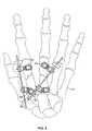
- FIG. 1is a side perspective view of one embodiment of the fixator.
- FIG. 2is a side perspective view of a second embodiment of the fixator.
- FIG. 3is a side and top view of one embodiment of a clamp system.
- FIG. 4is a side view of one embodiment of the fixator.
- FIG. 5is a top view of one embodiment of the fixator.
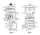
- FIG. 6is an angled view of one embodiment of parts of the clamp system.
- FIG. 7is a side view of one embodiment of the clamp system.
- a fixator 10comprises a rail 12 , at least one clamp system 14 , and a pin 16 .
- the clamp system 14is configured to attach to both the rail 12 and the pin 16 , which is connected to the bone 40 for fixation and stabilization.
- the fixator 10may further include compression and distraction nuts 18 functionally connected to the fixator 10 to allow for additional manipulation of bone healing and growth.
- the clamp systems 14can be splined to receive and hold rails 12 and pins 16 .
- the rails 12may be any size or shape, and persons of skill in the art will recognize that different application require rails 12 of many differing sizes or shapes, all of which are contemplated herein.
- the rails 12may, for example, have a circular, oblong, square, rectangular, or other-shaped cross section. Typically, however, the rails 12 have a round or circular cross-section and are sized in a manner suitable for fixation of small bones 41 , such as those of the foot or hand.
- the rails 12may be composed of many materials including, for example, carbon fiber or high density plastic, which allows the rod to be radiolucent.
- the rails 12may also be threaded to allow for attachment of clamp systems 14 , distraction/compression nuts 18 , or other components of a fixator 10 .
- the rail 12has a “negative” thread pattern, in which the threads 22 are grooves in the surface of the rail 12 rather than protrusions.
- reference to a threaded componentwill be a disclosure of both a positive and negative thread.
- the negative thread patternallows, for example, the clamp system 14 to easily slide up and down the rail 12 , while still allowing for the attachment of compression nuts 18 or other components which could be threaded onto the rail 12 . In such situations, the corresponding component, such as a compression nut 18 , will have a positive thread pattern.
- the rail 12has a thread pitch of approx 1 mm so one revolution of around the threaded rail 12 produces 1 mm of linear movement.
- the rail 12can be geared.
- the railhas a rack and pinion design 20 that allows for compression or distraction. This geared version can have a scale 24 indicating the amount of compression or distraction.
- the clamp system 14comprises a first clamp area 32 and a second clamp area 42 .
- the first clamp area 32comprises a pin clamp 34 while the second clamp area 42 comprises a rail or bar clamp 44 .
- the first clamp area 32is functionally connected to the second clamp area 42 such that the object held by the different clamp areas, either pins 16 or rails 12 , can lie in different planes.
- the first clamp area 32is a pin clamp 34 that can comprise a pin clamp top 36 , a pin clamp bottom 38 and a first clamp bolt 40 .
- the pin clamp top 36 and bottom 38are each configured to allow the first clamp bolt 40 to pass through them.
- the first clamp bolt 40is threaded, and the pin clamp top 36 and pin clamp bottom 38 have internal, threaded holes configured to receive the threaded first clamp bolt 40 .
- the pin clamp top 36 and bottom 38can be thought of as a set that together define at least one pin passage 33 capable of receiving the pin 16 .
- the pin clamp top and bottom 36 , 38each have inner surfaces 35 that together define two distinct pin passages 33 each capable of receiving the pin 16 .
- the inner surfaces 35 of the pin passages 33be textured to allow for more secure engagement of the pin 16 .
- the inner surfaces 35may have a 2 ⁇ diamond face with grooves 90 degrees to each other.
- other surfaces of the pin clamp top and bottom 36 , 38may be textured where a more secure engagement is desired.
- the two distinct pin passages 33are configured to receive the same size pin 16 .
- one pin passage 33is configured to receive one size pin 16 , for example a half pin, while the other pin passage 33 is configured to receive a second size pin 16 , for example a transfixing pin. It is contemplated that the pin passage 33 will extend in a direction substantially perpendicular to the first clamp bolt 40 .
- the pin clamp top and bottom 36 , 38can be rotated around the first clamp bolt 40 such that the pins 16 can be orientated in any direction in the plane perpendicular to the first clamp bolt 40 .
- the first clamp area 32further comprises another pin clamp 34 or a rail clamp 44 .
- An example of a first clamp area 32 with at least two pin clampscan be found in FIG. 7 .
- two sets of pin clamp top and bottom clamps 36 , 38can be arranged proximate each other on the pin clamp bolt 40 .
- four distinct pin passages 33each capable of receiving a pin 16 , can be defined by the pin clamp top and bottoms 36 , 38 .
- the first clamp area 32further comprises springs 46 which are functionally attached to the first clamp area 32 and that exert pressure on some of the pin clamp tops and bottoms 36 , 38 .
- the pin clamps 34can be “snap in.” That is, one can exert force on the pin clamp top and/or bottom 36 , 38 . When so doing, the pin clamp top and/or bottom 36 , 38 will push against the springs 46 and thereby be in a position that defines an opening 48 leading into the pin passage 33 capable of allowing the pin 16 to be pressed into that pin passage 33 . When the force is released, the springs 46 again exert full pressure on the pin clamp top and/or bottom 36 , 38 , causing the pin clamp top and bottom 36 , 38 set to clamp on the pin 16 and hold it in a fixed position. In addition, a nut 52 can then be tightened to more securely hold the rail 12 or pin 16 in place.
- the first clamp areafurther comprises a rail clamp 44 .
- the rail clamp 44comprises a rail clamp top 46 , a rail clamp bottom 47 and a rail clamp bolt 49 .
- the rail clamp top and bottom 46 , 47are each configured to allow the rail clamp bolt 49 to pass through them.
- the rail clamp bolt 49is threaded, and the rail clamp top and rail clamp bottom 46 , 47 have internal, threaded holes configured to receive the threaded rail clamp bolt 49 .
- the rail clamp top and bottom 46 , 47can be thought of as a set that together define at least one rail passage 54 capable of receiving the rail 12 .
- the inner surfaces 56 of the rail passage 54can be textured to allow for more secure engagement of the rail 12 .
- the inner surfaces 56may have a 2.times. diamond face with grooves 90 degrees to each other.
- other surfaces of the rail clamp top and bottom 46 , 47may be textured where a more secure engagement is desired.
- the first clamp area 32can comprise a rail clamp 44 and a pin clamp 34 .
- the rail passage 54can be in a different plane than the pin passage 33 .
- the first clamp area 32can be configured to allow for the rail 12 in the rail passage 54 to be disposed in a different direction than the pin 16 in the pin passage 33 .
- the pin 16may extend at an angle generally perpendicular to the bone or bones 41 to be fixed so that it can be anchored in the bone 41 while the rail 12 may extend at an angle generally parallel to the bone or bones 41 to be fixed.
- a hinge 60is attached to the first clamp bolt 40 proximate to either a pin or rail clamp bottom 38 , 47 .
- the hinge 60has a male element 62 and a female element 64 .
- the use of the terms male and female elements 62 , 64is not meant to suggest a certain structure, but only to disclose that the two elements are configured to work together to provide a hinged connection.
- the male element 62has a first section 66 and a second section 68 that are connected to each other.
- the first section and the second section 66 , 68can be disposed at about a 90 degree angle in relation to each other.
- the first section 66is configured to receive the first clamp bolt 40 by having a hole therethrough.
- the holemay be threaded. It is also preferred that the surface 69 of the first section 66 proximate the pin clamp 34 be textured. For example, the surface may have a 2 ⁇ diamond face with grooves 90 degrees to each other.
- the second section 28is configured to receive a hinge bolt 70 by having a hole therethrough. The hole may be threaded.
- the female element 64can have a first section 72 that is connected to a second section 74 , preferably at about a 90 degree angle in relation to each other.
- the first section 72 of the female element 64is preferably configured to receive a rail clamp bolt 49 by having a hole therethrough.
- the second section 74 of the female element 64can have a hole therethrough that is able to accommodate the hinge bolt 70 .
- the female element 64is hingedly connected to the male element 62 . In a preferred embodiment, both the female element 64 and the male element 62 are disposed on the hinge bolt 70 , and are held thereon by a hinge retaining washer or nut 76 .
- the hinge bolt 70 and retaining washer or nut 76are loose, the female element 64 can be rotated in relation to the male element 62 , and vice versa. To stabilize the connection, the hinge bolt 70 is tightened, thus holding the male element 62 against the female element 64 .
- the surfaces 78 of the female and male elements 62 , 64 that come into contact with each othermay be textured to increase friction and create a more stable connection.
- washers 80may be employed to ensure a stable connection.
- first clamp area 32is connected via the hinge 60 to the second clamp area 42 .
- the second clamp area 42can comprise a pin clamp 34 , a rail clamp 44 , or a combination of pin and rail clamps, 32 , 44 .
- each clamp system 14allows for multi-planar attachment of rails 12 and pins 16 .
- the clamp system 14comprises one clamp area.
- the one or more pin clamps 32 and one or more rail clamps 34can be linearly attached to the same bolt 82 .
- such a clamp systemcomprises one or more pin clamp tops 36 held in spaced relation to one or more corresponding pin clamp bottoms 38 .
- the pin clamp top and bottom 36 , 38define a pin passage 33 that can accept a pin 16 .
- the pin clamp tops and bottoms 36 , 38are configured with a hole therethrough that accepts a pin clamp bolt 82 .
- the pin clamp tops and bottoms 36 , 38can be loosened and tightened to accept a pin 16 and then securely attach to that pin 16 .
- This embodiment of a clamp system 14further comprises a clamp body 84 that preferably is configured with a hole therethrough that can accept the pin clamp bolt 82 .
- the clamp body 84can further define a rail passage 86 that is capable of accepting a rail 12 .
- the clamp body 84can further comprises a device, such as a bar clamp bolt 88 , that is capable of being screwed into the rail passage 86 to secure the rail 12 .
- the pins 16can be half pins or transfixing pins. In practice, one part of the pin 90 is set into a patient's bones while a second part of the pin 92 is attached to a clamp area 32 , 42 .
- the configuration of the fixator 10allows for such pins 16 to be placed prior to, during, or after assembly of the other parts of the fixator 10 without comprising the accuracy of the fixation.
- the fixator 10comprise more than one clamp system 14 .
- a first clamp system 14is preferably attached to a bone 41 at a first location.
- a second clamp system 14is preferably attached to a bone 41 , either the same bone, or a different bone, at a second location.
- the two clamp systems 14are connected by a rail 12 , to which both clamps systems 14 are attached via the rail clamp 44 .
- More than one clamp system 14 and more than one rail 12can be utilized.
- a first clamp system 14has a rail clamp 44 attached to a first rail 12 and a pin clamp 34 attached to two pins 16 .
- the pins 16are attached to a bone 41 at a first location.
- a second clamp system 14has a rail clamp 44 attached to the first rail 12 , and a pin clamp 34 attached to two different pins 16 , which are attached to a bone 41 at a second location.
- the second clamp system 14also has a second rail clamp 44 attached to a second rail 12 .
- a third clamp system 14has a rail clamp 44 attached to the second rail 12 and a pin clamp 34 attached to two pins 16 . These two pins 16 are attached to either the same bone 41 , or a different bone.
- the fixator 10 described herein, with each clamp system 14 capable of being comprised of one or more adjustable rail or pin clamps 44 , 34allows for a wide range of fixator 10 configurations that allow for effective treatment of a number of injuries.
- the clamps systems 14are adjustable with respect to the rail 12 in that each clamp system 14 can slide up or down the rail 12 and also rotate around the rail 12 freely. Once the optimum position for each clamp system 14 is obtained, the clamp system 12 may then be fixed securely in place by simply tightening the rail clamp 44 . Moreover, additional clamp systems 14 may be added to or removed from the fixator 10 easily, both prior to fixation and stabilization and at any point during the healing process, and any number of rail or pin clamps 44 , 34 may be used, depending upon the number of rails or pins 12 , 16 necessary for a given treatment.
- the pins 16can be placed independently of the fixator 10 because of the snap-in functionality of the clamp systems 14 and the ability of the fixator 10 to correct in all planes due to the multi-planar movement of the clamp systems 14 .
- compression nuts and distraction nuts 18can attached to the rails 12 and used in conjunction with the clamp systems 14 to further adjust bone healing and growth.
- the nuts 18may be used to move the clamp systems 14 incrementally along the rail 12 without moving the pins 16 or other components of the fixator 10 , thus providing additional correction on a minute scale during the healing or growth process.
- the compression nuts 18are preferably attached on the rail 12 such that, when moved, they will force two clamp systems 14 to move closer to each other.
- the distraction nuts 18are preferably attached on a rail 12 between two clamp systems 14 such that when the distraction nut 18 is moved, it will force one clamp system 14 away from the other.
- more than one compression and or distraction nuts 18can be attached to the same rail 12 to allow for compression or distraction, i.e., the movement of one or more than one clamp systems 14 in either direction along the rail 12 .
- the compression and distraction nuts 18may have built in washers.
- the compression and distraction nuts 18may have a positive thread and can be used in conjunction with a round rail 12 having a negative thread, as described previously.
- the fixator 10may be easily modified in many ways, such as for example to accommodate pins 16 of multiple diameters and lengths. Additionally, many various sizes and shapes of clamps systems 14 , rails 12 , and/or compression/distraction devices may be employed without detracting from the spirit of the invention. Clamp systems 14 , pins 16 , and rails 12 can be easily reproduced, for example, for medium and large applications as well, such as for use on long bones of the leg or arm.
- the fixator described hereincan be connected to various parts of the foot or other body parts without being limited by the configuration of the device. Further, the clamp systems 14 also have the mechanical ability to interconnect with other rails and fixation systems, allowing for multiple-rail systems or more complex applications.
- the fixatorcan be used in conjunction with foot plate (“U ring”) attachments, wires, Ilizarov fixators, or any other compatible external fixator device (none of which are shown) through the use of pins, wires (not shown), and/or transfixing pins.
- the fixator 10can be comprised of a wide variety of materials.
- the components of the fixator 10are composed of anodized aluminum, stainless steel, or composite polymer.
- the pins 16can be manufactured from 316L stainless steel and are preferably 2 mm, 2.5 mm, or 3 mm in length.
Landscapes
- Health & Medical Sciences (AREA)
- Orthopedic Medicine & Surgery (AREA)
- Life Sciences & Earth Sciences (AREA)
- Surgery (AREA)
- Biomedical Technology (AREA)
- Engineering & Computer Science (AREA)
- Nuclear Medicine, Radiotherapy & Molecular Imaging (AREA)
- Heart & Thoracic Surgery (AREA)
- Medical Informatics (AREA)
- Molecular Biology (AREA)
- Animal Behavior & Ethology (AREA)
- General Health & Medical Sciences (AREA)
- Public Health (AREA)
- Veterinary Medicine (AREA)
- Surgical Instruments (AREA)
Abstract
Description
Claims (20)
Priority Applications (4)
| Application Number | Priority Date | Filing Date | Title |
|---|---|---|---|
| US12/643,371US8235994B2 (en) | 2005-03-07 | 2009-12-21 | External fixator |
| US13/551,185US8486069B2 (en) | 2005-03-07 | 2012-07-17 | External fixator |
| US13/937,772US8808291B2 (en) | 2005-03-07 | 2013-07-09 | External fixator |
| US14/445,822US20160081718A9 (en) | 2005-03-07 | 2014-07-29 | External fixator |
Applications Claiming Priority (3)
| Application Number | Priority Date | Filing Date | Title |
|---|---|---|---|
| US65922705P | 2005-03-07 | 2005-03-07 | |
| US11/368,783US20060235383A1 (en) | 2005-03-07 | 2006-03-06 | External fixator |
| US12/643,371US8235994B2 (en) | 2005-03-07 | 2009-12-21 | External fixator |
Related Parent Applications (1)
| Application Number | Title | Priority Date | Filing Date |
|---|---|---|---|
| US11/368,783ContinuationUS20060235383A1 (en) | 2005-03-07 | 2006-03-06 | External fixator |
Related Child Applications (1)
| Application Number | Title | Priority Date | Filing Date |
|---|---|---|---|
| US13/551,185ContinuationUS8486069B2 (en) | 2005-03-07 | 2012-07-17 | External fixator |
Publications (2)
| Publication Number | Publication Date |
|---|---|
| US20100100096A1 US20100100096A1 (en) | 2010-04-22 |
| US8235994B2true US8235994B2 (en) | 2012-08-07 |
Family
ID=37109503
Family Applications (5)
| Application Number | Title | Priority Date | Filing Date |
|---|---|---|---|
| US11/368,783AbandonedUS20060235383A1 (en) | 2005-03-07 | 2006-03-06 | External fixator |
| US12/643,371Active2026-11-17US8235994B2 (en) | 2005-03-07 | 2009-12-21 | External fixator |
| US13/551,185ActiveUS8486069B2 (en) | 2005-03-07 | 2012-07-17 | External fixator |
| US13/937,772ActiveUS8808291B2 (en) | 2005-03-07 | 2013-07-09 | External fixator |
| US14/445,822AbandonedUS20160081718A9 (en) | 2005-03-07 | 2014-07-29 | External fixator |
Family Applications Before (1)
| Application Number | Title | Priority Date | Filing Date |
|---|---|---|---|
| US11/368,783AbandonedUS20060235383A1 (en) | 2005-03-07 | 2006-03-06 | External fixator |
Family Applications After (3)
| Application Number | Title | Priority Date | Filing Date |
|---|---|---|---|
| US13/551,185ActiveUS8486069B2 (en) | 2005-03-07 | 2012-07-17 | External fixator |
| US13/937,772ActiveUS8808291B2 (en) | 2005-03-07 | 2013-07-09 | External fixator |
| US14/445,822AbandonedUS20160081718A9 (en) | 2005-03-07 | 2014-07-29 | External fixator |
Country Status (1)
| Country | Link |
|---|---|
| US (5) | US20060235383A1 (en) |
Cited By (12)
| Publication number | Priority date | Publication date | Assignee | Title |
|---|---|---|---|---|
| US20130158551A1 (en)* | 2006-10-13 | 2013-06-20 | Stryker Trauma Sa | Prevention of re-use of a medical device |
| US9370380B2 (en) | 2013-03-15 | 2016-06-21 | Dne, Llc | External bone fixation system |
| US20160192964A1 (en)* | 2013-03-18 | 2016-07-07 | Orthofix S.R.L. | External fixation device |
| US9962188B2 (en) | 2013-10-29 | 2018-05-08 | Cardinal Health 247. Inc. | External fixation system and methods of use |
| US10245086B2 (en) | 2015-02-18 | 2019-04-02 | Treace Medical Concepts, Inc. | Bone plating kit for foot and ankle applications |
| US10245088B2 (en) | 2015-01-07 | 2019-04-02 | Treace Medical Concepts, Inc. | Bone plating system and method |
| US10258378B2 (en) | 2013-03-15 | 2019-04-16 | Dne, Llc | External bone fixation system |
| US11291476B2 (en) | 2016-06-10 | 2022-04-05 | Dne, Llc | External bone fixation system |
| US11583323B2 (en) | 2018-07-12 | 2023-02-21 | Treace Medical Concepts, Inc. | Multi-diameter bone pin for installing and aligning bone fixation plate while minimizing bone damage |
| US11849933B2 (en)* | 2020-04-24 | 2023-12-26 | Medartis Ag | Bone align and joint preparation device and method |
| US11890039B1 (en) | 2019-09-13 | 2024-02-06 | Treace Medical Concepts, Inc. | Multi-diameter K-wire for orthopedic applications |
| US12440250B2 (en) | 2024-02-05 | 2025-10-14 | Treace Medical Concepts, Inc. | Multi-diameter K-wire for orthopedic applications |
Families Citing this family (34)
| Publication number | Priority date | Publication date | Assignee | Title |
|---|---|---|---|---|
| EP1700571B1 (en)* | 2003-11-25 | 2008-07-30 | Instituto Tecnologico de Canarias, S.A. (ITC) | External wrist-fixing device |
| US20060225157A1 (en)* | 2005-03-30 | 2006-10-05 | Sw Seed Ltd. | Canola variety SW 013154 |
| DE202005005444U1 (en)* | 2005-04-01 | 2005-06-02 | Tantum Ag | Particularly stable bone fixing device, assembled of two central elements and two fixing rods holding devices |
| US8277448B2 (en)* | 2007-03-07 | 2012-10-02 | Wright Medical Technology, Inc. | External fixation |
| IT1391406B1 (en)* | 2008-09-11 | 2011-12-23 | Orthofix Srl | ORTHOPEDIC SUPPORT DEVICE FOR A KNEE JOINT |
| ES2451507T3 (en)* | 2009-05-15 | 2014-03-27 | Stryker Trauma Ag | Fixing flange |
| US8282636B2 (en)* | 2009-08-10 | 2012-10-09 | Imds Corporation | Orthopedic external fixator and method of use |
| US8858555B2 (en) | 2009-10-05 | 2014-10-14 | Stryker Trauma Sa | Dynamic external fixator and methods for use |
| US20110160772A1 (en)* | 2009-12-28 | 2011-06-30 | Arcenio Gregory B | Systems and methods for performing spinal fusion |
| EP2417924B1 (en) | 2010-08-11 | 2015-07-01 | Stryker Trauma SA | External fixator system |
| US11141196B2 (en) | 2010-08-11 | 2021-10-12 | Stryker European Operations Holdings Llc | External fixator system |
| US8945128B2 (en) | 2010-08-11 | 2015-02-03 | Stryker Trauma Sa | External fixator system |
| US9168064B2 (en)* | 2012-07-17 | 2015-10-27 | Ellen Hokanson | Bilateral dynamic external distractor for the treatment of complex fracture luxations of the proximal interphalangeal joint of the hand |
| US9101398B2 (en) | 2012-08-23 | 2015-08-11 | Stryker Trauma Sa | Bone transport external fixation frame |
| US9155561B2 (en) | 2013-03-06 | 2015-10-13 | Stryker Trauma Sa | Mini-rail external fixator |
| US9408635B2 (en) | 2013-03-15 | 2016-08-09 | Wright Medical Technology, Inc. | External fixation |
| WO2015167581A1 (en) | 2014-05-02 | 2015-11-05 | Wright Medical Technology, Inc. | Circular fixator system and method |
| CN106308912A (en)* | 2014-10-24 | 2017-01-11 | 烟台小米机械技术有限公司 | Hand bone fixer for preventing osteonecrosis |
| US10531896B2 (en) | 2015-08-10 | 2020-01-14 | Stryker European Holdings I, Llc | Distraction tube with wire clamp |
| US9936976B2 (en)* | 2016-03-01 | 2018-04-10 | Pbd, Patent & Business Development Ag | Bracket for external fixation of bones |
| US10342580B2 (en) | 2016-03-01 | 2019-07-09 | Pbd, Patent & Business Development Ag | Bracket for external fixation of bones |
| EP3422972B8 (en)* | 2016-03-01 | 2020-01-15 | AMDT Holdings, Inc. | External bone fixation systems |
| US11013545B2 (en)* | 2018-05-30 | 2021-05-25 | Acumed Llc | Distraction/compression apparatus and method for bone |
| US11596443B2 (en)* | 2018-07-11 | 2023-03-07 | Treace Medical Concepts, Inc. | Compressor-distractor for angularly realigning bone portions |
| US10695095B2 (en)* | 2018-08-21 | 2020-06-30 | New Standard Device, LLC | Orthopedic strut with multiple attachment clamps |
| WO2020095217A1 (en)* | 2018-11-06 | 2020-05-14 | Moradi Ali | External orthopedic fixation device |
| US11607250B2 (en) | 2019-02-13 | 2023-03-21 | Treace Medical Concepts, Inc. | Tarsal-metatarsal joint procedure utilizing compressor-distractor and instrument providing sliding surface |
| US11889998B1 (en) | 2019-09-12 | 2024-02-06 | Treace Medical Concepts, Inc. | Surgical pin positioning lock |
| US11864798B2 (en) | 2019-09-30 | 2024-01-09 | Gitlin LLC | Y-frame external bone fixator |
| US11737786B2 (en) | 2019-12-31 | 2023-08-29 | Orthopediatrics Corp. | Multiple track system for positioning of bone segments |
| USD1057155S1 (en) | 2022-02-23 | 2025-01-07 | Treace Medical Concepts, Inc. | Lesser metatarsal cut guide with parallel cut faces |
| USD1011524S1 (en) | 2022-02-23 | 2024-01-16 | Treace Medical Concepts, Inc. | Compressor-distractor for the foot |
| USD1051382S1 (en) | 2022-02-23 | 2024-11-12 | Treace Medical Concepts, Inc. | Lesser metatarsal cut guide |
| USD1079011S1 (en) | 2022-02-23 | 2025-06-10 | Treace Medical Concepts, Inc. | Metatarsal cut guide with parallel cut faces |
Citations (39)
| Publication number | Priority date | Publication date | Assignee | Title |
|---|---|---|---|---|
| US4365624A (en) | 1979-01-16 | 1982-12-28 | Jaquet Orthopedie Sa | External bone-anchoring element |
| US4393868A (en) | 1981-02-20 | 1983-07-19 | Ace Orthopedic Manufacturing Inc. | Colles fracture fixature device |
| WO1985003449A1 (en) | 1984-02-08 | 1985-08-15 | Ben Dov Meir | Bone growth stimulator |
| US4604997A (en) | 1984-02-13 | 1986-08-12 | Orthofix S.R.L. | Articulated mini external fixation device |
| US4611586A (en) | 1983-10-06 | 1986-09-16 | John M. Agee | Articulated Colles' fracture splint |
| US4620533A (en) | 1985-09-16 | 1986-11-04 | Pfizer Hospital Products Group Inc. | External bone fixation apparatus |
| US4628919A (en) | 1983-09-09 | 1986-12-16 | Clyburn Terry | Dynamic external fixator and method of use |
| US4920959A (en) | 1986-04-04 | 1990-05-01 | Ulrich Witzel | External fixture for osteosynthetis |
| US4922896A (en) | 1989-05-05 | 1990-05-08 | John M. Agee | Colles' fracture splint |
| US4978347A (en) | 1988-07-26 | 1990-12-18 | Ilizarov Gavrill A | Distraction apparatus for osteosynthesis of short tubular bones |
| US5067954A (en) | 1988-07-25 | 1991-11-26 | Ilizarov Gavriil A | Distraction apparatus for plastic reconstruction of hand |
| US5108394A (en) | 1989-09-08 | 1992-04-28 | Kabushiki Kaisha Nagano Keiki Seisakusho | Bone fixing device |
| US5320622A (en)* | 1992-07-28 | 1994-06-14 | Orthofix S.R.L. | Dynamic axial splint |
| US5397322A (en) | 1990-08-03 | 1995-03-14 | Jaquet Orthopedie S.A. | Manipulator for external bone fixation devices |
| US5437667A (en) | 1992-11-10 | 1995-08-01 | Innovative Orthopaedics, Manufacturing, Inc. | Dynamic external fixator for the wrist |
| US5527309A (en) | 1993-04-21 | 1996-06-18 | The Trustees Of Columbia University In The City Of New York | Pelvo-femoral fixator |
| US5571103A (en) | 1994-10-18 | 1996-11-05 | Bailey; Kirk J. | Method for the fixation of bone |
| US5591169A (en) | 1994-06-14 | 1997-01-07 | Benoist; Louis | Device and method for positioning and holding bone fragments in place |
| US5658283A (en) | 1995-02-15 | 1997-08-19 | Huebner; Randall J. | External fixator for repairing fractures |
| US5662649A (en) | 1995-02-15 | 1997-09-02 | Huebner; Randall J. | External fixator for repairing fractures of distal radius and wrist |
| US5683389A (en) | 1994-12-05 | 1997-11-04 | Smith & Nephew, Inc. | External fixator for distal radius fractures |
| WO1998012975A2 (en) | 1996-09-26 | 1998-04-02 | Aleksandar Tosic | Articulated external orthopedic fixation system and method of use |
| US5741251A (en) | 1997-01-07 | 1998-04-21 | Benoist; Louis | Device and method for reducing and stabilizing a bone fracture |
| US5743898A (en) | 1995-05-12 | 1998-04-28 | Electro-Biology, Inc. | Method and apparatus for external fixation of small bones |
| US5810814A (en) | 1994-09-27 | 1998-09-22 | Newson; Charles James | Bone fixing screw pin |
| US5891144A (en)* | 1996-05-10 | 1999-04-06 | Jaquet Orthopedie S.A. | External fixator |
| US5941879A (en) | 1997-11-18 | 1999-08-24 | Electro-Biology, Inc. | Method and apparatus for external fixation of bones |
| US6001097A (en) | 1996-01-18 | 1999-12-14 | Jaquet Orthopedie S.A. | Fracture reducing apparatus |
| US6053915A (en) | 1998-09-02 | 2000-04-25 | Bruchmann; Guillermo Victorio | External tutor for the treatment of radius distal end fractures |
| US6283964B1 (en) | 1998-02-20 | 2001-09-04 | Lon S. Weiner | Modular fixator assembly |
| US6328737B1 (en) | 1997-04-11 | 2001-12-11 | Keel University | Fracture reduction device |
| US6428540B1 (en) | 1996-11-13 | 2002-08-06 | Synthes (U.S.A.) | Device for repositioning fractured bone fragments |
| US6527775B1 (en) | 2000-09-22 | 2003-03-04 | Piper Medical, Inc. | Intramedullary interlocking fixation device for the distal radius |
| US20030187432A1 (en)* | 2002-03-28 | 2003-10-02 | Johnson Tab C. | External fixation system |
| US6629976B1 (en) | 1999-11-01 | 2003-10-07 | Sulzer Orthopedics, Ltd. | Radius marrow nail |
| US6716212B1 (en) | 2002-01-25 | 2004-04-06 | Tyrone Sam Pickens | Universal modular external fixation system |
| US20040133200A1 (en) | 2002-11-15 | 2004-07-08 | Ruch David S. | Apparatus and method for maintaining bones in a healing position |
| US20050043730A1 (en) | 2002-02-11 | 2005-02-24 | Pioneer Laboratories, Inc. | External fixation apparatus and method |
| US6866665B2 (en) | 2003-03-27 | 2005-03-15 | Hand Innovations, Llc | Bone fracture fixation system with subchondral and articular surface support |
Family Cites Families (3)
| Publication number | Priority date | Publication date | Assignee | Title |
|---|---|---|---|---|
| US4895141A (en)* | 1984-04-26 | 1990-01-23 | Harrington Arthritis Research Center | Unilateral external fixation device |
| CH690293A5 (en)* | 1994-09-06 | 2000-07-14 | Jaquet Orthopedie | Joint for components of an external fixator. |
| US7048735B2 (en)* | 2002-02-04 | 2006-05-23 | Smith & Nephew | External fixation system |
- 2006
- 2006-03-06USUS11/368,783patent/US20060235383A1/ennot_activeAbandoned
- 2009
- 2009-12-21USUS12/643,371patent/US8235994B2/enactiveActive
- 2012
- 2012-07-17USUS13/551,185patent/US8486069B2/enactiveActive
- 2013
- 2013-07-09USUS13/937,772patent/US8808291B2/enactiveActive
- 2014
- 2014-07-29USUS14/445,822patent/US20160081718A9/ennot_activeAbandoned
Patent Citations (41)
| Publication number | Priority date | Publication date | Assignee | Title |
|---|---|---|---|---|
| US4365624A (en) | 1979-01-16 | 1982-12-28 | Jaquet Orthopedie Sa | External bone-anchoring element |
| US4393868A (en) | 1981-02-20 | 1983-07-19 | Ace Orthopedic Manufacturing Inc. | Colles fracture fixature device |
| US4628919A (en) | 1983-09-09 | 1986-12-16 | Clyburn Terry | Dynamic external fixator and method of use |
| US4611586A (en) | 1983-10-06 | 1986-09-16 | John M. Agee | Articulated Colles' fracture splint |
| WO1985003449A1 (en) | 1984-02-08 | 1985-08-15 | Ben Dov Meir | Bone growth stimulator |
| US4604997A (en) | 1984-02-13 | 1986-08-12 | Orthofix S.R.L. | Articulated mini external fixation device |
| US4620533A (en) | 1985-09-16 | 1986-11-04 | Pfizer Hospital Products Group Inc. | External bone fixation apparatus |
| US4920959A (en) | 1986-04-04 | 1990-05-01 | Ulrich Witzel | External fixture for osteosynthetis |
| US5067954A (en) | 1988-07-25 | 1991-11-26 | Ilizarov Gavriil A | Distraction apparatus for plastic reconstruction of hand |
| US4978347A (en) | 1988-07-26 | 1990-12-18 | Ilizarov Gavrill A | Distraction apparatus for osteosynthesis of short tubular bones |
| US4922896A (en) | 1989-05-05 | 1990-05-08 | John M. Agee | Colles' fracture splint |
| US5108394A (en) | 1989-09-08 | 1992-04-28 | Kabushiki Kaisha Nagano Keiki Seisakusho | Bone fixing device |
| US5397322A (en) | 1990-08-03 | 1995-03-14 | Jaquet Orthopedie S.A. | Manipulator for external bone fixation devices |
| US5320622A (en)* | 1992-07-28 | 1994-06-14 | Orthofix S.R.L. | Dynamic axial splint |
| US5437667A (en) | 1992-11-10 | 1995-08-01 | Innovative Orthopaedics, Manufacturing, Inc. | Dynamic external fixator for the wrist |
| US5527309A (en) | 1993-04-21 | 1996-06-18 | The Trustees Of Columbia University In The City Of New York | Pelvo-femoral fixator |
| US5591169A (en) | 1994-06-14 | 1997-01-07 | Benoist; Louis | Device and method for positioning and holding bone fragments in place |
| US5810814A (en) | 1994-09-27 | 1998-09-22 | Newson; Charles James | Bone fixing screw pin |
| US5571103A (en) | 1994-10-18 | 1996-11-05 | Bailey; Kirk J. | Method for the fixation of bone |
| US5683389A (en) | 1994-12-05 | 1997-11-04 | Smith & Nephew, Inc. | External fixator for distal radius fractures |
| US6793655B2 (en) | 1994-12-05 | 2004-09-21 | Smith & Nephew, Inc. | External fixator for distal radius fractures |
| US20030109879A1 (en) | 1994-12-05 | 2003-06-12 | Orsak James E. | External fixator for distal radius fractures |
| US5662649A (en) | 1995-02-15 | 1997-09-02 | Huebner; Randall J. | External fixator for repairing fractures of distal radius and wrist |
| US5658283A (en) | 1995-02-15 | 1997-08-19 | Huebner; Randall J. | External fixator for repairing fractures |
| US5743898A (en) | 1995-05-12 | 1998-04-28 | Electro-Biology, Inc. | Method and apparatus for external fixation of small bones |
| US6001097A (en) | 1996-01-18 | 1999-12-14 | Jaquet Orthopedie S.A. | Fracture reducing apparatus |
| US5891144A (en)* | 1996-05-10 | 1999-04-06 | Jaquet Orthopedie S.A. | External fixator |
| WO1998012975A2 (en) | 1996-09-26 | 1998-04-02 | Aleksandar Tosic | Articulated external orthopedic fixation system and method of use |
| US6428540B1 (en) | 1996-11-13 | 2002-08-06 | Synthes (U.S.A.) | Device for repositioning fractured bone fragments |
| US5741251A (en) | 1997-01-07 | 1998-04-21 | Benoist; Louis | Device and method for reducing and stabilizing a bone fracture |
| US6328737B1 (en) | 1997-04-11 | 2001-12-11 | Keel University | Fracture reduction device |
| US5941879A (en) | 1997-11-18 | 1999-08-24 | Electro-Biology, Inc. | Method and apparatus for external fixation of bones |
| US6283964B1 (en) | 1998-02-20 | 2001-09-04 | Lon S. Weiner | Modular fixator assembly |
| US6053915A (en) | 1998-09-02 | 2000-04-25 | Bruchmann; Guillermo Victorio | External tutor for the treatment of radius distal end fractures |
| US6629976B1 (en) | 1999-11-01 | 2003-10-07 | Sulzer Orthopedics, Ltd. | Radius marrow nail |
| US6527775B1 (en) | 2000-09-22 | 2003-03-04 | Piper Medical, Inc. | Intramedullary interlocking fixation device for the distal radius |
| US6716212B1 (en) | 2002-01-25 | 2004-04-06 | Tyrone Sam Pickens | Universal modular external fixation system |
| US20050043730A1 (en) | 2002-02-11 | 2005-02-24 | Pioneer Laboratories, Inc. | External fixation apparatus and method |
| US20030187432A1 (en)* | 2002-03-28 | 2003-10-02 | Johnson Tab C. | External fixation system |
| US20040133200A1 (en) | 2002-11-15 | 2004-07-08 | Ruch David S. | Apparatus and method for maintaining bones in a healing position |
| US6866665B2 (en) | 2003-03-27 | 2005-03-15 | Hand Innovations, Llc | Bone fracture fixation system with subchondral and articular surface support |
Non-Patent Citations (2)
| Title |
|---|
| Gradl, et al., "Fractures of the Distal Radius Treated With a Nonbridging External Fixation Technique Using Multiplanar K-Wires", The Journal of Hand Surgery, 2005, 30A:960-968. |
| Synthes (USA), "External Fixation", 2000, 2 pages. |
Cited By (23)
| Publication number | Priority date | Publication date | Assignee | Title |
|---|---|---|---|---|
| US9549762B2 (en)* | 2006-10-13 | 2017-01-24 | Stryker European Holdings I, Llc | Prevention of re-use of a medical device |
| US20130158551A1 (en)* | 2006-10-13 | 2013-06-20 | Stryker Trauma Sa | Prevention of re-use of a medical device |
| US10687853B2 (en) | 2013-03-15 | 2020-06-23 | Dne, Llc | External bone fixation system |
| US9370380B2 (en) | 2013-03-15 | 2016-06-21 | Dne, Llc | External bone fixation system |
| US10022152B2 (en) | 2013-03-15 | 2018-07-17 | Dne, Llc | External bone fixation system |
| US11986218B2 (en) | 2013-03-15 | 2024-05-21 | Trilliant Surgical, Llc | External bone fixation system |
| US11259843B2 (en) | 2013-03-15 | 2022-03-01 | Dne, Llc | External bone fixation system |
| US10258378B2 (en) | 2013-03-15 | 2019-04-16 | Dne, Llc | External bone fixation system |
| US20160192964A1 (en)* | 2013-03-18 | 2016-07-07 | Orthofix S.R.L. | External fixation device |
| US9750536B2 (en)* | 2013-03-18 | 2017-09-05 | Orthofix S.R.L. | External fixation device |
| US9962188B2 (en) | 2013-10-29 | 2018-05-08 | Cardinal Health 247. Inc. | External fixation system and methods of use |
| US11154340B2 (en) | 2015-01-07 | 2021-10-26 | Treace Medical Concepts, Inc. | Bone plating system and method |
| US10245088B2 (en) | 2015-01-07 | 2019-04-02 | Treace Medical Concepts, Inc. | Bone plating system and method |
| US12059185B2 (en) | 2015-01-07 | 2024-08-13 | Treace Medical Concepts, Inc. | Bone plating system and method |
| US11344347B2 (en) | 2015-02-18 | 2022-05-31 | Treace Medical Concepts, Inc. | Bone plating kit for foot and ankle applications |
| US10245086B2 (en) | 2015-02-18 | 2019-04-02 | Treace Medical Concepts, Inc. | Bone plating kit for foot and ankle applications |
| US11291476B2 (en) | 2016-06-10 | 2022-04-05 | Dne, Llc | External bone fixation system |
| US12016592B2 (en) | 2016-06-10 | 2024-06-25 | Trilliant Surgical, Llc | External bone fixation system |
| US11583323B2 (en) | 2018-07-12 | 2023-02-21 | Treace Medical Concepts, Inc. | Multi-diameter bone pin for installing and aligning bone fixation plate while minimizing bone damage |
| US11890039B1 (en) | 2019-09-13 | 2024-02-06 | Treace Medical Concepts, Inc. | Multi-diameter K-wire for orthopedic applications |
| US11849933B2 (en)* | 2020-04-24 | 2023-12-26 | Medartis Ag | Bone align and joint preparation device and method |
| US12310572B2 (en) | 2020-04-24 | 2025-05-27 | Medartis Ag | Bone align and joint preparation device and method |
| US12440250B2 (en) | 2024-02-05 | 2025-10-14 | Treace Medical Concepts, Inc. | Multi-diameter K-wire for orthopedic applications |
Also Published As
| Publication number | Publication date |
|---|---|
| US8486069B2 (en) | 2013-07-16 |
| US20120283736A1 (en) | 2012-11-08 |
| US20130296858A1 (en) | 2013-11-07 |
| US20100100096A1 (en) | 2010-04-22 |
| US20160081718A9 (en) | 2016-03-24 |
| US8808291B2 (en) | 2014-08-19 |
| US20060235383A1 (en) | 2006-10-19 |
| US20140336650A1 (en) | 2014-11-13 |
Similar Documents
| Publication | Publication Date | Title |
|---|---|---|
| US8235994B2 (en) | External fixator | |
| US20240358410A1 (en) | External bone fixation system | |
| US8147491B2 (en) | Multi-angle clamp | |
| CA1176529A (en) | Colles fracture fixature device | |
| US6162223A (en) | Dynamic wrist fixation apparatus for early joint motion in distal radius fractures | |
| US20030187432A1 (en) | External fixation system | |
| US20050203509A1 (en) | Device and method for fixing bone segments | |
| US20040133200A1 (en) | Apparatus and method for maintaining bones in a healing position | |
| US10258378B2 (en) | External bone fixation system | |
| WO2007001945A1 (en) | Adjustable fixation clamp and method | |
| US20240415544A1 (en) | External bone fixation system | |
| US11918252B2 (en) | Deformable dynamization device | |
| WO2015117207A1 (en) | Tightening joints for versatile modular systems for osteosynthesis | |
| US9408635B2 (en) | External fixation | |
| KR20200105352A (en) | External fixation device for fractures made by carbon fiber | |
| EP4312833A1 (en) | Stable locking fixation of threaded bone pins and other components of ring external fixator | |
| SU1607794A1 (en) | Compression-distruction apparatus | |
| BG61553B1 (en) | External fixture |
Legal Events
| Date | Code | Title | Description |
|---|---|---|---|
| STCF | Information on status: patent grant | Free format text:PATENTED CASE | |
| FPAY | Fee payment | Year of fee payment:4 | |
| AS | Assignment | Owner name:MIDCAP FINANCIAL TRUST, AS AGENT, MARYLAND Free format text:SECURITY INTEREST;ASSIGNOR:WRIGHT MEDICAL TECHNOLOGY, INC.;REEL/FRAME:041257/0126 Effective date:20161223 | |
| MAFP | Maintenance fee payment | Free format text:PAYMENT OF MAINTENANCE FEE, 8TH YEAR, LARGE ENTITY (ORIGINAL EVENT CODE: M1552); ENTITY STATUS OF PATENT OWNER: LARGE ENTITY Year of fee payment:8 | |
| AS | Assignment | Owner name:INBONE TECHNOLOGIES, INC., TENNESSEE Free format text:RELEASE BY SECURED PARTY;ASSIGNOR:MIDCAP FUNDING IV TRUST;REEL/FRAME:054480/0001 Effective date:20201112 Owner name:TORNIER US HOLDINGS, INC., MINNESOTA Free format text:RELEASE BY SECURED PARTY;ASSIGNOR:MIDCAP FUNDING IV TRUST;REEL/FRAME:054480/0001 Effective date:20201112 Owner name:TORNIER, INC., MINNESOTA Free format text:RELEASE BY SECURED PARTY;ASSIGNOR:MIDCAP FUNDING IV TRUST;REEL/FRAME:054480/0001 Effective date:20201112 Owner name:WRIGHT MEDICAL GROUP, INC., TENNESSEE Free format text:RELEASE BY SECURED PARTY;ASSIGNOR:MIDCAP FUNDING IV TRUST;REEL/FRAME:054480/0001 Effective date:20201112 Owner name:WRIGHT MEDICAL CAPITAL, INC., TENNESSEE Free format text:RELEASE BY SECURED PARTY;ASSIGNOR:MIDCAP FUNDING IV TRUST;REEL/FRAME:054480/0001 Effective date:20201112 Owner name:WRIGHT MEDICAL GROUP N.V., NETHERLANDS Free format text:RELEASE BY SECURED PARTY;ASSIGNOR:MIDCAP FUNDING IV TRUST;REEL/FRAME:054480/0001 Effective date:20201112 Owner name:SOLANA SURGICAL, LLC, TENNESSEE Free format text:RELEASE BY SECURED PARTY;ASSIGNOR:MIDCAP FUNDING IV TRUST;REEL/FRAME:054480/0001 Effective date:20201112 Owner name:BIOMIMETIC THERAPEUTICS USA, INC., TENNESSEE Free format text:RELEASE BY SECURED PARTY;ASSIGNOR:MIDCAP FUNDING IV TRUST;REEL/FRAME:054480/0001 Effective date:20201112 Owner name:WRIGHT MEDICAL GROUP INTELLECTUAL PROPERTY, INC., TENNESSEE Free format text:RELEASE BY SECURED PARTY;ASSIGNOR:MIDCAP FUNDING IV TRUST;REEL/FRAME:054480/0001 Effective date:20201112 Owner name:ORTHOHELIX SURGICAL DESIGNS, INC., MINNESOTA Free format text:RELEASE BY SECURED PARTY;ASSIGNOR:MIDCAP FUNDING IV TRUST;REEL/FRAME:054480/0001 Effective date:20201112 Owner name:BIOMIMETIC THERAPEUTICS, LLC, TENNESSEE Free format text:RELEASE BY SECURED PARTY;ASSIGNOR:MIDCAP FUNDING IV TRUST;REEL/FRAME:054480/0001 Effective date:20201112 Owner name:ORTHOPRO, L.L.C., TENNESSEE Free format text:RELEASE BY SECURED PARTY;ASSIGNOR:MIDCAP FUNDING IV TRUST;REEL/FRAME:054480/0001 Effective date:20201112 Owner name:BIOMIMETIC THERAPEUTICS CANADA, INC., TENNESSEE Free format text:RELEASE BY SECURED PARTY;ASSIGNOR:MIDCAP FUNDING IV TRUST;REEL/FRAME:054480/0001 Effective date:20201112 Owner name:WHITE BOX ORTHOPEDICS, LLC, TENNESSEE Free format text:RELEASE BY SECURED PARTY;ASSIGNOR:MIDCAP FUNDING IV TRUST;REEL/FRAME:054480/0001 Effective date:20201112 Owner name:TROOPER HOLDINGS INC., MINNESOTA Free format text:RELEASE BY SECURED PARTY;ASSIGNOR:MIDCAP FUNDING IV TRUST;REEL/FRAME:054480/0001 Effective date:20201112 Owner name:WRIGHT MEDICAL TECHNOLOGY, INC., TENNESSEE Free format text:RELEASE BY SECURED PARTY;ASSIGNOR:MIDCAP FUNDING IV TRUST;REEL/FRAME:054480/0001 Effective date:20201112 | |
| MAFP | Maintenance fee payment | Free format text:PAYMENT OF MAINTENANCE FEE, 12TH YEAR, LARGE ENTITY (ORIGINAL EVENT CODE: M1553); ENTITY STATUS OF PATENT OWNER: LARGE ENTITY Year of fee payment:12 |