US8235988B2 - Systems and methods for reduction of atrial fibrillation - Google Patents
Systems and methods for reduction of atrial fibrillationDownload PDFInfo
- Publication number
- US8235988B2 US8235988B2US12/359,223US35922309AUS8235988B2US 8235988 B2US8235988 B2US 8235988B2US 35922309 AUS35922309 AUS 35922309AUS 8235988 B2US8235988 B2US 8235988B2
- Authority
- US
- United States
- Prior art keywords
- electrode
- catheter
- pulmonary vein
- tissue
- tip portion
- Prior art date
- Legal status (The legal status is an assumption and is not a legal conclusion. Google has not performed a legal analysis and makes no representation as to the accuracy of the status listed.)
- Active, expires
Links
- 238000000034methodMethods0.000titleclaimsdescription37
- 206010003658Atrial FibrillationDiseases0.000titledescription12
- 230000009467reductionEffects0.000titledescription4
- 210000003492pulmonary veinAnatomy0.000claimsabstractdescription75
- 238000002679ablationMethods0.000claimsabstractdescription41
- 210000005246left atriumAnatomy0.000claimsdescription18
- 238000010438heat treatmentMethods0.000claimsdescription4
- 239000006260foamSubstances0.000claimsdescription3
- 210000002837heart atriumAnatomy0.000abstractdescription7
- 210000001519tissueAnatomy0.000description50
- 230000008569processEffects0.000description10
- 239000000463materialSubstances0.000description6
- 238000011282treatmentMethods0.000description5
- 206010003119arrhythmiaDiseases0.000description4
- 230000006793arrhythmiaEffects0.000description4
- 230000037361pathwayEffects0.000description4
- 230000008901benefitEffects0.000description3
- 230000002999depolarising effectEffects0.000description3
- 239000003814drugSubstances0.000description3
- 229940079593drugDrugs0.000description3
- 238000009998heat settingMethods0.000description3
- 230000007246mechanismEffects0.000description3
- 230000004048modificationEffects0.000description3
- 238000012986modificationMethods0.000description3
- 208000008883Patent Foramen OvaleDiseases0.000description2
- 230000002159abnormal effectEffects0.000description2
- 210000003484anatomyAnatomy0.000description2
- 230000001746atrial effectEffects0.000description2
- 230000008602contractionEffects0.000description2
- 230000000694effectsEffects0.000description2
- 239000013013elastic materialSubstances0.000description2
- 230000001788irregularEffects0.000description2
- 210000003205muscleAnatomy0.000description2
- 229910001000nickel titaniumInorganic materials0.000description2
- HLXZNVUGXRDIFK-UHFFFAOYSA-Nnickel titaniumChemical compound[Ti].[Ti].[Ti].[Ti].[Ti].[Ti].[Ti].[Ti].[Ti].[Ti].[Ti].[Ni].[Ni].[Ni].[Ni].[Ni].[Ni].[Ni].[Ni].[Ni].[Ni].[Ni].[Ni].[Ni].[Ni]HLXZNVUGXRDIFK-UHFFFAOYSA-N0.000description2
- 230000004044responseEffects0.000description2
- 210000005245right atriumAnatomy0.000description2
- 210000001013sinoatrial nodeAnatomy0.000description2
- 206010003662Atrial flutterDiseases0.000description1
- 208000001871TachycardiaDiseases0.000description1
- 230000009471actionEffects0.000description1
- 206010003668atrial tachycardiaDiseases0.000description1
- 230000005540biological transmissionEffects0.000description1
- 238000013153catheter ablationMethods0.000description1
- 230000008859changeEffects0.000description1
- 238000006243chemical reactionMethods0.000description1
- 238000004891communicationMethods0.000description1
- 230000008878couplingEffects0.000description1
- 238000010168coupling processMethods0.000description1
- 238000005859coupling reactionMethods0.000description1
- 230000007812deficiencyEffects0.000description1
- 230000001066destructive effectEffects0.000description1
- 239000003989dielectric materialSubstances0.000description1
- 208000002173dizzinessDiseases0.000description1
- 230000001747exhibiting effectEffects0.000description1
- 206010016256fatigueDiseases0.000description1
- 210000003191femoral veinAnatomy0.000description1
- 210000005003heart tissueAnatomy0.000description1
- 238000003384imaging methodMethods0.000description1
- 239000007943implantSubstances0.000description1
- 238000003698laser cuttingMethods0.000description1
- 238000004519manufacturing processMethods0.000description1
- 230000001575pathological effectEffects0.000description1
- 238000007517polishing processMethods0.000description1
- 229920000642polymerPolymers0.000description1
- 230000001902propagating effectEffects0.000description1
- 239000012858resilient materialSubstances0.000description1
- 230000001020rhythmical effectEffects0.000description1
- 239000004576sandSubstances0.000description1
- 229910001285shape-memory alloyInorganic materials0.000description1
- 238000007493shaping processMethods0.000description1
- 230000002269spontaneous effectEffects0.000description1
- 230000004936stimulating effectEffects0.000description1
- -1surgerySubstances0.000description1
- 238000001356surgical procedureMethods0.000description1
- 208000024891symptomDiseases0.000description1
- 230000001360synchronised effectEffects0.000description1
- 230000006794tachycardiaEffects0.000description1
- 210000003462veinAnatomy0.000description1
Images


Classifications
- A—HUMAN NECESSITIES
- A61—MEDICAL OR VETERINARY SCIENCE; HYGIENE
- A61B—DIAGNOSIS; SURGERY; IDENTIFICATION
- A61B18/00—Surgical instruments, devices or methods for transferring non-mechanical forms of energy to or from the body
- A61B18/04—Surgical instruments, devices or methods for transferring non-mechanical forms of energy to or from the body by heating
- A61B18/12—Surgical instruments, devices or methods for transferring non-mechanical forms of energy to or from the body by heating by passing a current through the tissue to be heated, e.g. high-frequency current
- A61B18/14—Probes or electrodes therefor
- A61B18/1492—Probes or electrodes therefor having a flexible, catheter-like structure, e.g. for heart ablation
- A—HUMAN NECESSITIES
- A61—MEDICAL OR VETERINARY SCIENCE; HYGIENE
- A61B—DIAGNOSIS; SURGERY; IDENTIFICATION
- A61B18/00—Surgical instruments, devices or methods for transferring non-mechanical forms of energy to or from the body
- A61B18/04—Surgical instruments, devices or methods for transferring non-mechanical forms of energy to or from the body by heating
- A61B18/08—Surgical instruments, devices or methods for transferring non-mechanical forms of energy to or from the body by heating by means of electrically-heated probes
- A61B18/082—Probes or electrodes therefor
- A—HUMAN NECESSITIES
- A61—MEDICAL OR VETERINARY SCIENCE; HYGIENE
- A61B—DIAGNOSIS; SURGERY; IDENTIFICATION
- A61B18/00—Surgical instruments, devices or methods for transferring non-mechanical forms of energy to or from the body
- A61B18/18—Surgical instruments, devices or methods for transferring non-mechanical forms of energy to or from the body by applying electromagnetic radiation, e.g. microwaves
- A—HUMAN NECESSITIES
- A61—MEDICAL OR VETERINARY SCIENCE; HYGIENE
- A61B—DIAGNOSIS; SURGERY; IDENTIFICATION
- A61B17/00—Surgical instruments, devices or methods
- A61B2017/00367—Details of actuation of instruments, e.g. relations between pushing buttons, or the like, and activation of the tool, working tip, or the like
- A—HUMAN NECESSITIES
- A61—MEDICAL OR VETERINARY SCIENCE; HYGIENE
- A61B—DIAGNOSIS; SURGERY; IDENTIFICATION
- A61B17/00—Surgical instruments, devices or methods
- A61B2017/0046—Surgical instruments, devices or methods with a releasable handle; with handle and operating part separable
- A—HUMAN NECESSITIES
- A61—MEDICAL OR VETERINARY SCIENCE; HYGIENE
- A61B—DIAGNOSIS; SURGERY; IDENTIFICATION
- A61B17/00—Surgical instruments, devices or methods
- A61B17/0057—Implements for plugging an opening in the wall of a hollow or tubular organ, e.g. for sealing a vessel puncture or closing a cardiac septal defect
- A61B2017/00575—Implements for plugging an opening in the wall of a hollow or tubular organ, e.g. for sealing a vessel puncture or closing a cardiac septal defect for closure at remote site, e.g. closing atrial septum defects
- A—HUMAN NECESSITIES
- A61—MEDICAL OR VETERINARY SCIENCE; HYGIENE
- A61B—DIAGNOSIS; SURGERY; IDENTIFICATION
- A61B17/00—Surgical instruments, devices or methods
- A61B2017/00831—Material properties
- A61B2017/00867—Material properties shape memory effect
- A—HUMAN NECESSITIES
- A61—MEDICAL OR VETERINARY SCIENCE; HYGIENE
- A61B—DIAGNOSIS; SURGERY; IDENTIFICATION
- A61B18/00—Surgical instruments, devices or methods for transferring non-mechanical forms of energy to or from the body
- A61B2018/00053—Mechanical features of the instrument of device
- A61B2018/00214—Expandable means emitting energy, e.g. by elements carried thereon
- A61B2018/0022—Balloons
- A—HUMAN NECESSITIES
- A61—MEDICAL OR VETERINARY SCIENCE; HYGIENE
- A61B—DIAGNOSIS; SURGERY; IDENTIFICATION
- A61B18/00—Surgical instruments, devices or methods for transferring non-mechanical forms of energy to or from the body
- A61B2018/00053—Mechanical features of the instrument of device
- A61B2018/00214—Expandable means emitting energy, e.g. by elements carried thereon
- A61B2018/00267—Expandable means emitting energy, e.g. by elements carried thereon having a basket shaped structure
- A—HUMAN NECESSITIES
- A61—MEDICAL OR VETERINARY SCIENCE; HYGIENE
- A61B—DIAGNOSIS; SURGERY; IDENTIFICATION
- A61B18/00—Surgical instruments, devices or methods for transferring non-mechanical forms of energy to or from the body
- A61B2018/00315—Surgical instruments, devices or methods for transferring non-mechanical forms of energy to or from the body for treatment of particular body parts
- A61B2018/00345—Vascular system
- A61B2018/00351—Heart
- A61B2018/00375—Ostium, e.g. ostium of pulmonary vein or artery
- A—HUMAN NECESSITIES
- A61—MEDICAL OR VETERINARY SCIENCE; HYGIENE
- A61B—DIAGNOSIS; SURGERY; IDENTIFICATION
- A61B18/00—Surgical instruments, devices or methods for transferring non-mechanical forms of energy to or from the body
- A61B2018/00571—Surgical instruments, devices or methods for transferring non-mechanical forms of energy to or from the body for achieving a particular surgical effect
- A61B2018/00577—Ablation
- A—HUMAN NECESSITIES
- A61—MEDICAL OR VETERINARY SCIENCE; HYGIENE
- A61B—DIAGNOSIS; SURGERY; IDENTIFICATION
- A61B18/00—Surgical instruments, devices or methods for transferring non-mechanical forms of energy to or from the body
- A61B2018/00636—Sensing and controlling the application of energy
- A61B2018/00773—Sensed parameters
- A61B2018/00839—Bioelectrical parameters, e.g. ECG, EEG
- A—HUMAN NECESSITIES
- A61—MEDICAL OR VETERINARY SCIENCE; HYGIENE
- A61B—DIAGNOSIS; SURGERY; IDENTIFICATION
- A61B18/00—Surgical instruments, devices or methods for transferring non-mechanical forms of energy to or from the body
- A61B18/04—Surgical instruments, devices or methods for transferring non-mechanical forms of energy to or from the body by heating
- A61B18/12—Surgical instruments, devices or methods for transferring non-mechanical forms of energy to or from the body by heating by passing a current through the tissue to be heated, e.g. high-frequency current
- A61B18/14—Probes or electrodes therefor
- A61B2018/1405—Electrodes having a specific shape
- A61B2018/1435—Spiral
- A—HUMAN NECESSITIES
- A61—MEDICAL OR VETERINARY SCIENCE; HYGIENE
- A61B—DIAGNOSIS; SURGERY; IDENTIFICATION
- A61B5/00—Measuring for diagnostic purposes; Identification of persons
- A61B5/24—Detecting, measuring or recording bioelectric or biomagnetic signals of the body or parts thereof
- A61B5/25—Bioelectric electrodes therefor
- A61B5/279—Bioelectric electrodes therefor specially adapted for particular uses
- A61B5/28—Bioelectric electrodes therefor specially adapted for particular uses for electrocardiography [ECG]
- A61B5/283—Invasive
- A—HUMAN NECESSITIES
- A61—MEDICAL OR VETERINARY SCIENCE; HYGIENE
- A61M—DEVICES FOR INTRODUCING MEDIA INTO, OR ONTO, THE BODY; DEVICES FOR TRANSDUCING BODY MEDIA OR FOR TAKING MEDIA FROM THE BODY; DEVICES FOR PRODUCING OR ENDING SLEEP OR STUPOR
- A61M25/00—Catheters; Hollow probes
- A61M25/01—Introducing, guiding, advancing, emplacing or holding catheters
- A61M2025/0183—Rapid exchange or monorail catheters
- A—HUMAN NECESSITIES
- A61—MEDICAL OR VETERINARY SCIENCE; HYGIENE
- A61M—DEVICES FOR INTRODUCING MEDIA INTO, OR ONTO, THE BODY; DEVICES FOR TRANSDUCING BODY MEDIA OR FOR TAKING MEDIA FROM THE BODY; DEVICES FOR PRODUCING OR ENDING SLEEP OR STUPOR
- A61M25/00—Catheters; Hollow probes
- A61M25/10—Balloon catheters
- A61M2025/1043—Balloon catheters with special features or adapted for special applications
- A61M2025/1047—Balloon catheters with special features or adapted for special applications having centering means, e.g. balloons having an appropriate shape
- A—HUMAN NECESSITIES
- A61—MEDICAL OR VETERINARY SCIENCE; HYGIENE
- A61M—DEVICES FOR INTRODUCING MEDIA INTO, OR ONTO, THE BODY; DEVICES FOR TRANSDUCING BODY MEDIA OR FOR TAKING MEDIA FROM THE BODY; DEVICES FOR PRODUCING OR ENDING SLEEP OR STUPOR
- A61M25/00—Catheters; Hollow probes
- A61M25/10—Balloon catheters
- A61M2025/1043—Balloon catheters with special features or adapted for special applications
- A61M2025/1052—Balloon catheters with special features or adapted for special applications for temporarily occluding a vessel for isolating a sector
Definitions
- the present inventionrelates generally to ablation systems and methods and, more specifically, to systems and methods for reduction of atrial fibrillation including various electrode configurations and ablation catheter systems.
- the heartincludes a number of pathways that are responsible for the propagation of signals necessary to produce continuous, synchronized contractions.
- Each contraction cyclebegins in the right atrium where a sinoatrial node initiates an electrical impulse. This impulse then spreads across the right atrium to the left atrium, stimulating the atria causing them to contract.
- the chain reactioncontinues from the atria to the ventricles by passing through a pathway known as the atrioventricular (AV) node or junction, which acts as an electrical gateway to the ventricles.
- AV junctiondelivers the signal to the ventricles while also slowing or delaying it, so the atria can relax before the ventricles contract.
- Irregular heart beatsor arrhythmia
- arrhythmiaare caused by physiological or pathological disturbances in the discharge of electrical impulses from the sinoatrial node, in the transmission of the signal through the heart tissue, or by spontaneous, unexpected electrical signals generated within the heart.
- arrhythmiais tachycardia, which is an abnormal rapidity of heart action.
- atrial tachycardiaThere are several different forms of atrial tachycardia, including atrial fibrillation and atrial flutter. With atrial fibrillation, instead of a single beat, numerous electrical impulses are generated by depolarizing tissue at one or more locations in the atria (or possibly other locations). These unexpected electrical impulses produce irregular, often rapid heartbeats in the atrial muscles and ventricles. Patients experiencing atrial fibrillation may suffer from fatigue, activity intolerance, dizziness and even strokes.
- Atrial fibrillation treatment techniquesare available, including drugs, surgery, implants, and catheter ablation. While drugs may be the treatment of choice for some patients, drugs typically only mask the symptoms and do not cure the underlying cause. Implantable devices, on the other hand, usually correct an arrhythmia only after it occurs, but do not cure the condition or prevent arrhythmias from occurring again in the future. Surgical and catheter-based treatments, in contrast, will actually cure the problem by ablating the abnormal tissue or accessory pathway responsible for the atrial fibrillation.
- the catheter-based treatmentsrely on the application of various destructive energy sources to the target tissue, including direct current electrical energy, radiofrequency (RF) electrical energy, laser energy, and the like.
- the energy sourcesuch as an ablating electrode, is conventionally disposed along a distal portion of a catheter.
- a related concernentails understanding the electrical characteristics of the tissue surrounding the PV prior to ablation. For example, for atrial fibrillation, it is necessary to identify the origination point of the undesired electrical impulses prior to ablation. Typically, an entirely separate catheter is employed for understanding the characteristics of the tissue prior to beginning an ablation process with an ablation catheter. These additional steps greatly increase the overall time required to complete the procedure.
- an ablation catheterthat better conforms to the anatomy and overcomes the deficiencies of the conventional “straight ended” ablation catheter. Further, it may be desirable to provide an ablation catheter that does not require the additional acts that greatly increase the overall time required to understand the electrical characteristics of the tissue surrounding the PV.
- the present inventionis directed to an ablation catheter system configured, for example, to ablate tissue adjacent an ostium of the pulmonary vein in a left atria of a heart.
- the ablation catheter systemincludes a handle including an actuator and a catheter coupled to the handle defining a lumen extending through a length of the catheter, the catheter including a tip portion at a distal end thereof.
- the ablation catheter systemalso includes an electrode coupled to the handle with lines extending through the lumen of the catheter, the electrode being configured to be constrained within the tip portion of the catheter and configured to be deployed from the tip portion and self expand to an expanded configuration.
- the electrodeis configured to self expand to a substantially conical configuration with a tip portion configured to be disposed within the pulmonary vein.
- the ablation catheter systemincludes an energy source coupled to the electrode.
- the electrodeincludes one or more sensors coupled to a sensor display.
- the energy sourcemay include or be coupled to a return electrode.
- the electrodein another embodiment, includes a multi-cellular structure that is configured to expand radially outward.
- the electrodeincludes a tip portion configured to self center the electrode within a pulmonary vein with a proximal portion of the electrode configured to abut against tissue adjacent the ostium of the pulmonary vein.
- the tip portionincludes a first lumen and a second lumen, wherein the first lumen coincides with the lumen of the catheter and the second lumen is positioned adjacent the first lumen and is configured to engage a guide wire in facilitating access to the left atrium of the heart.
- the ablation catheter systemincludes a push rod coupled to the electrode and is configured to stabilize the electrode.
- the present inventionis directed to an electrode coupled to an ablation catheter system configured to ablate tissue adjacent an ostium of a pulmonary vein in a left atrium of a heart.
- the electrodeincludes a frame including multiple struts defining center portion cells, intermediate cells and outer cells.
- the intermediate cellsbeing disposed between the center portion cells and the outer cells, and further, the intermediate cells extending radially outward from the center portion cells and the outer cells extending radially outward from the intermediate cells.
- the frameis configured to move between a constricted narrow configuration and a radially self expanding configuration. Further, in one embodiment, the frame is configured to self expand to a conical configuration.
- the electrodeincludes center portion cells having common struts with the intermediate cells.
- the intermediate cellsinclude common struts with the center portion cells and the outer cells.
- the outer cellsinclude attachment structures, such as eyelets, configured to attach lines extending to the ablation catheter system.
- the frameis configured to self expand with a flange portion.
- a flange portioncan be defined from at least one of the outer cells and the intermediate cells of the frame.
- the center portion cellscan include a tip portion of the self expanded configuration of the electrode. Further, the tip portion is configured to self center the frame over the ostium of the pulmonary vein.
- the frameincludes one or more sensors configured to sense characteristics of tissue adjacent the ostium of the pulmonary vein.
- the framecomprises a super elastic material.
- a catheter system for heating tissue adjacent an ostium of a pulmonary veinincludes a catheter having a proximal portion and a distal portion.
- An RF energy sourceis operatively connected with the catheter and an electrode coupled to the RF energy source.
- the electrodeis positioned adjacent the distal portion of the catheter and configured to heat at least one segment adjacent the ostium of the pulmonary vein.
- a method of ablating tissue adjacent an ostium of a pulmonary veinincludes disposing an electrode adjacent a pulmonary vein and placing a centering device at least partially within the pulmonary vein.
- the electrodeis positioned against tissue at or near the ostium of the pulmonary vein subsequent placing the centering device and Energy is provided to the electrode to ablate the tissue contacted by the electrode.
- a method of ablating tissue adjacent an ostium of a pulmonary veinincludes disposing an electrode adjacent a pulmonary vein. Tissue is contacted with the electrode electrical characteristics of the tissue are measured through the electrode. The electrode is positioned in response to the measured electrical characteristics and tissue is ablated with the electrode.
- FIG. 1shows a catheter system configured to enter the left atrium of the heart to ablate tissue adjacent the pulmonary vein, according to an embodiment of the present invention
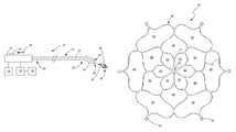
- FIG. 2shows the catheter system in FIG. 1 with a self expanding electrode deployed from the catheter system, according to an embodiment of the present invention
- FIG. 3is a partial cross-sectional view depicting another embodiment of the self expanding electrode with a pusher rod integrated with the catheter system, according to another embodiment of the present invention
- FIG. 3Ais a partial cross-sectional view depicting the electrode of FIG. 3 in a constricted configuration being recaptured by the catheter, according to an embodiment of the present invention
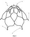
- FIGS. 4 and 5illustrate top and perspective views of the self expanding electrode, according to an embodiment of the present invention
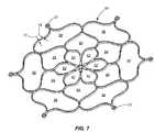
- FIGS. 6 and 7illustrate top and perspective views of the self expanding electrode in a substantially flat configuration, according to another embodiment of the present invention.
- FIGS. 8A-8Cillustrate an electrode according to an embodiment of the present invention
- FIGS. 9 and 10illustrate electrodes according to additional embodiments of the present invention.
- FIG. 11shows an electrode with an expansion device according to an embodiment of the present invention
- FIG. 12shows an electrode according to yet another embodiment of the present invention.
- FIGS. 13 and 14show electrodes utilized with centering devices according to an embodiment of the present invention
- FIGS. 15A and 15Billustrate electrodes according to additional embodiments of the present invention.
- FIGS. 16A and 16Billustrate electrodes according to additional embodiments of the present invention.
- FIGS. 17A and 17Bshow an electrode and catheter system according to an embodiment of the present invention
- FIG. 18shows an electrode according to another embodiment of the present invention.
- FIGS. 19A-19Cshow an electrode and catheter system according to another embodiment of the present invention.
- FIGS. 20 and 21show electrodes according to additional embodiments of the present invention.
- FIG. 22shows a catheter system in accordance with another embodiment of the present invention.
- a catheter system 10which is configured to enter a left atrium of the heart (not shown) according to an embodiment of the invention.
- a catheter system 10includes an electrode 50 that is sized and configured to ablate tissue at the ostium of the pulmonary vein within the left atrium of the heart.
- the catheter system 10includes a handle 12 , a catheter 20 and the electrode 50 disposed within a tip portion 22 of the catheter 20 .
- the catheter system 10may also include an energy source 14 , a return electrode 16 and a sensor display 18 configured to display information being received from one or more sensors within or near the electrode 50 .
- the catheter system 10 of the presently considered embodimentis configured to be employed as an ablation catheter under a uni-polar system, utilizing the return electrode 16 .
- the ablation catheter of the present inventioncan be utilized as a bi-polar system with minor modification.
- the handle 12may include an actuator 24 configured to deploy the electrode 50 from the catheter 20 as well as recapture or re-sheath the electrode 50 within the catheter 20 .
- the catheter 20includes a proximal portion 26 and a distal portion 28 with a lumen 30 extending through the length of the catheter 20 .
- the catheter 20is incorporated with the handle 12 .
- the distal portion 28 of the catheter 20includes the tip portion 22 .
- the tip portion 22may include a lumen that extends from, and coincides and is in communication with, the lumen 30 of the catheter 20 . Such tip portion 22 is configured to house or hold the electrode 50 in a constricted and contained configuration.
- the electrode 50is interconnected to the handle 12 via lines 32 (or tethers) and a push rod (see FIGS. 3 and 4 ) that can extend through a portion of, or fully through, the length of the lumen 30 of the catheter 20 .
- the tip portion 22may also include a rapid exchange (Rx) lumen 34 to facilitate accessing the left atrium of the heart via a guide wire (not shown).
- Rx lumen 34disposed in a non-coaxial arrangement with the lumen 30 of the catheter 20 or tip portion 22 , is fully disclosed in Applicant's previously filed patent application, U.S. patent application Ser. No. 11/836,051, filed Aug. 8, 2007, the disclosure of which is hereby incorporated by reference in its entirety.
- the currently described catheter system 10may also be adapted to facilitate over the wire access to the left atrium of the heart.
- the catheter system 10may be seen with the electrode 50 in a non-deployed position ( FIG. 1 ) and a deployed position ( FIG. 2 ).
- the actuator 24 on the handle 12can be manually moved as shown by arrow 36 from the position shown in FIG. 1 to the position shown in FIG. 2 .
- a push-rod(not shown in FIGS. 1 and 2 ) may be associated with the actuator 24 to displace the electrode 50 in relationship to the tip 22 of the catheter 20 .
- the actuator 24may be configured to move the catheter 20 proximally (relative to a push-rod or other structure) to facilitate un-sheathing the electrode 50 from the tip portion 22 of the catheter 20 .
- the electrode 50can be configured to automatically self expand to an enlarged, un-constricted and expanded configuration.
- Such expanded configuration of the electrode 50may include a conical configuration or the like or any other shaped configuration, such as partially conical with a proximal outward extending flange, that will maximize the preferred area for ablating tissue at the ostium of the pulmonary vein. Further detail regarding the structure of the electrode 50 will be discussed below.
- the electrode 50may be configured to move between a deployed configuration and the constrained non-deployed configuration within the tip portion 22 .
- the actuator 24may be utilized to displace the catheter 20 and recapture or resheath the electrode 50 .
- the electrodemay be configured to be substantially flat when in a substantially unconstrained state. In such a case, the electrode may be configured to contact a greater area of tissue surrounding the ostium of a pulmonary vein.
- the catheter 20can access the left atrium of the heart via a guide wire (not shown).
- the guide wirecan be pushed through the femoral vein to access the left atrium via a trans-septal puncture using, for example, known techniques in the art.
- the distal portion 28 of the catheter 20can then access the left atrium by inserting the proximal end of the guide wire through the Rx lumen 34 of the tip portion 22 .
- the catheter 20is then moved distally through the vein to access the left atrium and the electrode 50 may be deployed from the tip portion 22 of the catheter 20 .
- the electrode 50may be positioned over the ostium of the pulmonary veins with a distal end of the electrode 50 extending within the pulmonary vein.
- the electrode 50can be used to measure electrical signals of the muscle tissue with sensors on the electrode 50 (or with the electrode itself). Such sensors can determine characteristics of the tissue. This sensing of the tissue can facilitate the determination of which portion(s) of the tissue adjacent the pulmonary vein need to be treated and the proper position of the electrode 50 for such treatment.
- the electrode 50itself may be used as a sensor, with one or more additional electrodes (e.g., a return electrode 16 ) acting in concert with the electrode 50 positioned at or near the pulmonary vein.
- additional electrodese.g., a return electrode 16
- specific components or areas of the electrode 50may be electrically isolated from one another such that the “electrode 50 ” itself acts as multiple electrodes.
- the electrode 50may be used, for example, as an EKG electrode during one stage of the process while being used as a heating or ablating electrode during another stage of the process.
- the one or more sensorsmay be coupled to a controller for evaluating the electrical signals generated by such sensors.
- the sensorsmay also be coupled to a display 18 to provide feed back to the physician, based on the signals generated by the sensors, so the physician may understand and evaluate the characteristics of the tissue. This further helps the physician in understanding what the proper position and orientation of the electrode 50 should be, as well as the amount of energy or heat that should be applied to the tissue, in order to obtain the desired results from the ablative process.
- the physiciancan then place the electrode 50 over the ostium and heat the tissue with RF energy (or other energy) via the energy source 14 in a manner consistent with that which was determined in the exploratory or investigative process.
- the electrode 50may include a multi-cellular structure and exhibit generally conical or other tapered configuration. Such an electrode 50 is configured to maximize the tissue area at the ostium that is heated with the energy from the energy source 14 .
- the generally conical configuration of the electrode 50provides an inherent self centering feature by positioning a distal tip of the conical structure within the pulmonary vein and moving the electrode 50 forward so that the electrode 50 is positioned against the tissue adjacent the ostium of the pulmonary vein. After heating the tissue, the electrode 50 can again be utilized for sensing the characteristics of the tissue in order to determine if the tissue has been sufficiently treated as desired. This process can then be repeated in treating the tissue at the ostium for each of the four pulmonary veins as determined from the electrode 50 . Once complete, the electrode 50 can be recaptured within the tip portion 22 of the catheter and withdrawn from the patient.
- FIG. 3a cross-sectional view of an electrode 50 is shown wherein a push rod 36 is utilized to assist in the placement and recapture of the electrode 50 during an ablation procedure.
- the electrode 50is coupled with a push rod 36 which may extend coaxially with an axis of the tip portion 22 of the catheter 20 (not shown in FIG. 3 ).
- the push rod 36may include a distal portion 38 configured to be attached with a center portion 40 of the electrode 50 .
- the push rod 36may be attached to the electrode 50 by way of generally radially-extending struts (not shown) in an umbrella-like configuration. In such a configuration, the struts may be attached symmetrically to various intermediate portions of the electrode 50 .
- a strut configurationmay be used in conjunction with (rather than in place of) attachment of the push rod 36 to the center portion 40 of the electrode 50 .
- the push rod 36may be employed to provide a pushing force, indicated by arrow 42 , when the electrode 50 is positioned over the ostium of the pulmonary vein.
- the push rod 36can be utilized to act in conjunction with the tethers or lines 32 when recapturing the electrode 50 within the tip portion 22 of the catheter 20 .
- the lines 32may be coupled to the proximal attachment points 52 of the electrode 50 and extend proximally through, for example, an inner sheath 44 or ring.
- the push rod 36can be used as leverage to hold the distal portion of the electrode 50 steady while the lines 32 are moved proximally (or the inner sheath 44 is moved distally—or both), thereby, pulling the proximal attachment points 52 or ends of the electrode 50 in a radially constricted and narrow configuration to be recaptured within the tip portion 22 of the catheter 20 .
- the electrode 50may include a distal portion 54 , which may also be referred to as a tip portion (and may correspond to the center portion 40 ), and a proximal portion 56 being at an opposite end of the electrode 50 .
- the proximal portion 56is radially expanded as compared to the distal portion 54 .
- the radially expanded proximal portion 56may include the attachment points 52 in the form of, for example, eyelets, for attachment of the lines (see, e.g., FIGS. 2 and 3 ).
- the electrode 50may be formed from a flat sheet of super elastic material, such as Nitinol material.
- the electrode 50can be laser cut from such flat sheet of material and then shaped or heat set to the desired configuration. Such heat setting can be employed in, for example, a heated sand bath utilizing techniques known to those of ordinary skill in the art.
- the electrodemay include, or be formed from, other materials as known in the art.
- FIGS. 6 and 7illustrate the electrode 50 during manufacturing thereof prior to shaping or heat setting the electrode such that it exhibits a generally conical configuration.
- the electrodemay be formed from a flat sheet of Nitinol or other appropriate material.
- a laser cutting process and an electro polishing processmay be used to cut and form the initial configuration of the electrode.
- the electrodemay be formed as a unitary structure.
- the electrode 50can be formed, via a heat setting process, to provide a self expanding conical configuration.
- the electrodemay be deformed to a constrained configuration (e.g., when stored within the catheter tip prior to deployment) and expand into a desired shape (e.g., generally conical where the proximal end 56 extends radially further than does the distal end 54 ) upon release from a constricting force (again, such as when released from the catheter tip).
- the electrode 50may self expand from a constricted or collapsed configuration to a substantially flat shape (i.e., the radially outer portion and the center portion lie substantially within the same plane) and be utilized to ablate tissue surrounding the ostium of the pulmonary vein.
- the electrode 50may be selectively configured, in terms of shape, size and orientation, during use thereof.
- the electrode 50may be used in a flat configuration to treat an area surrounding the ostium of a pulmonary vein, it may be used in a conical configuration to treat a portion of the pulmonary vein or the ostium itself or it may be selectively configured to exhibit a desired amount of taper between a “flat” configuration and a fully deployed conical configuration.
- Selectively configuring the geometry of the electrodefurther enables tailoring of its placement so that ablation of specific tissue may be accomplished more effectively. Such selective configuring may be accomplished, for example, by manipulating the push rod 36 and lines 32 to effect a desired configuration.
- an electrode 50may include a frame 60 having multiple cells or a multi-cellular configuration.
- the multi-cellular configurationcan include center portion cells 62 , intermediate cells 64 and outer cells 66 each being defined by multiple struts 70 , the combination of struts 70 and cells ( 62 , 64 and 66 ) defining the frame 60 or at least a portion thereof.
- the center portion cells 62may collectively exhibit a flower like configuration.
- the center portion cells 62may include free ends 68 that each extend toward a center 76 or axis of the frame 60 . In such an embodiment, such center portion cells may be considered to be “open” cells since the free ends 68 are not joined to form a closed periphery.
- one or more of the free ends 68may be coupled to the push rod ( FIGS. 3 and 3A ) for deployment and recapture purposes as discussed above.
- the ends of the center portion cellsmay be interconnected (i.e., not free ends) to form a center cell and, therefore, defining closed periphery cells as the center portion cells 62 .
- a push rodmay be coupled to a portion of the periphery defining the center cell.
- the intermediate cells 64may share common struts 70 adjacent center portion cells 62 .
- a single strut 70may be partially define a center portion cell 62 as well as partially define an intermediate cell 64 .
- the intermediate cells 64may share common struts 70 to both the center portion cells 62 and the outer cells 66 .
- the center portion cells 62 , intermediate cells 64 and the outer cells 66build upon each other in a radially outward and symmetrical arrangement. It is noted, however, that asymmetrical configurations are also contemplated.
- Attachment points 52which may include, for example, an eyelet, may be formed or coupled to a portion (e.g., a radially-most outward portion) of the outer cells 66 for coupling the distal ends of the lines or tethers (see e.g., FIGS. 2 and 3 ).
- the frame 60may also include markers (not shown), such as radio-opaque markers or other markers known in the art, for imaging purposes.
- the struts 70 defining the center portion cells 62may be symmetrical to one another.
- the struts for the intermediate cells 64may be symmetrical with each other and the struts 70 for the outer cells 66 may be symmetrical with one another.
- the electrode 50can symmetrically expand and constrict, thereby limiting the strain and stress placed on the struts 70 when moving between an expanded and constricted configuration.
- the frame 60can be sized and configured such that the struts 70 for each of the cells can include tapered portions so as to manipulate the behavior of the frame 60 , while maintaining structural integrity, when the frame or electrode is moved between the deployed configuration and the constrained configuration within the tip portion of the catheter 20 .
- a strutmay change in cross-sectional area (taken substantially transverse to its length) as it extends along its length. Further, the aspect ratio of a depth 72 and a width 74 of the struts can be manipulated to increase the structural integrity of the frame 60 when being moved between expanded and constricted configurations.
- the electrode 100may be formed from a tube having cuts or slits 102 formed along a portion of its length.
- the cuts or slits 102define strut members 104 .
- the electrode 100may take the form as shown in FIG. 8A when disposed within a catheter (not shown) for delivery to a desired location within a patient's heart. When in the delivery configuration, the struts 104 are substantially elongated.
- the longitudinal ends 106 and 108 of the electrode 104may be displaced toward one another (such as by push rods, tethers and the like) such that the struts 104 become curved or bent and have portions displaced radially outward as indicated in FIGS. 8B and 8C .
- the radially outward portions of the struts 104may then be used to contact a desired area within the heart, such as the pulmonary vein, the ostium of the pulmonary vein or surrounding tissue.
- the electrode 100may be recaptured within a catheter by displacing the ends 106 and 108 away from each other so that the struts 104 are again elongated (such as shown in FIG.
- Electrode 8Aand electrode may be drawn back into the catheter. It is noted that a similarly shaped electrode may be formed by other means such as by use of wire or other material wherein the electrode is self expanding to the configuration shown in FIGS. 8B and 8C . While four struts are shown to be used in FIGS. 8A-8C , such is not to be considered limiting and other numbers of struts are contemplated as being utilized.
- FIG. 9another electrode 110 is shown which exhibits a configuration of a substantially helical coil.
- a similarly shaped electrode 120is shown in FIG. 10 .
- the electrode 110 of FIG. 9is configured to be a connected at a proximal end 112 thereof, while the electrode 120 of FIG. 10 is configured with a connection at a distal end 122 thereof.
- Such electrodes 110 and 120may be formed of wire, a shape memory alloy, or from other appropriate material.
- an electrode 130is shown having an expansion device 132 associated therewith.
- the expansion device 132may include, for example, a balloon or self-expanding foam.
- the use of an expansion device 132may assist in expanding the electrode and effecting contact of the electrode with the surrounding tissue. Additionally, the expansion device 132 may be used to help center or otherwise position the electrode with respect to the pulmonary vein 134 .
- FIG. 12shows another embodiment of an electrode 140 that includes multiple arms 142 shaped and configured to engage the ostium of a pulmonary vein 134 .
- the arms 142may include distal portions 146 sized and shaped to enter the pulmonary vein 134 , while the arms 142 flare radially outwardly so as to have a portion of the electrode 140 that is wider than ostium and, therefore contacts or engages the ostium (and/or tissue surrounding the ostium) of the pulmonary vein 134 .
- an electrode 150is shown that is associated with a centering device 152 .
- the centering device 152may include, for example, expandable foam, a balloon, or some other body or resilient material.
- the centering device 152may be disposed within the pulmonary vein 134 so as to assist in positioning the electrode 150 at a desired location.
- the electrodemay be configured according to any of the various electrodes described herein or even according to known electrode configurations.
- FIG. 14shows a similar mechanism having a centering device 152 with a differently configured electrode 160 .
- the electrode shown in FIG. 14includes a generally ring shaped structure which may be configured as an open loop 162 with a single end of the electrode 160 extending through the catheter 164 , as shown in FIG. 15A , or as a closed loop 166 with two ends of the electrode extending into the catheter 164 , as shown in FIG. 15B .
- the electrodes 170 and 180generally have multiple arms 172 and 182 shaped and configured to engage the ostium of a pulmonary vein 134 .
- the arms 172 and 182may include distal portions 174 and 184 sized and shaped to enter the pulmonary vein 134 , while the arms 172 and 182 flare radially outwardly so as to have a portion of the electrodes 170 and 180 that is wider than ostium and, therefore contacts or engages the ostium of the pulmonary vein 134 .
- the electrode 180 shown in FIG. 16Bis formed in a closed loop configuration as compared the electrode 170 shown in FIG. 16A .
- the electrode 188includes a radially expanding structure 190 such as a stent-like device or a resilient polymer structure.
- the radially expanding structure 190may extend along a push-rod 192 or other structure and be radially constricted such that it fits within a lumen of a catheter 194 .
- a distal end 196 of the radially expanding structuremay be coupled with the push-rod 192 while a proximal end 198 of the push-rod 192 may be configured, when released from the lumen of the catheter 194 , to abut against a surface of the catheter 194 .
- the catheter 194 and push rod 192may then be displaced relative to each other, such as shown in FIG. 17B , so that the radially expanding structure 190 becomes shortened and expands radially.
- the electrode 188having been expanded radially, now contacts tissue within the pulmonary vein 134 , at the ostium, or both.
- the push-rod 192may act as a centering device to help locate the electrode 188 relative to the pulmonary vein 134 .
- Tethers, or other mechanismsmay be coupled with the proximal end of the radially expanding structure 190 to help recapture the electrode for repositioning or after an ablation process is complete.
- another electrode 200may include amore conventional stent-like device that is expanded, for example, by a balloon or other mechanism to engage tissue associated with a pulmonary vein 134 .
- an electrode 210may include a spring 212 or other helical spring-like structure contained within a lumen of a catheter 214 .
- a push-rod 216may be coupled to a distal end of the spring 212 to assist in deploying the spring 212 from the catheter 214 .
- the spring 212While in the catheter 214 , the spring 212 may be radially constricted such that it expands radially when released from the lumen as indicated in FIG. 19B .
- a proximal end of the spring 212may then abut a surface of the catheter (e.g., an end surface) and the catheter 214 and push-rod 216 may be displaced relative to each other to shorten the length of the spring 212 .
- the longitudinally compressed spring 212may then be placed in contact with the ostium of the pulmonary vein 134 as indicated in FIG. 19C .
- the electrodemay be recaptured in a manner such as previously described. It is noted that the electrode may also be deployed and recaptured by twisting the ends of the spring 212 relative to each other so as to alter the diameter of the spring 212 .
- annular electrode 220is shown as an example of a bipolar electrode having a conductive inner surface 222 which may act as a first pole and a conductive outer surface 224 may act as a another pole.
- the two conductive surfaces 222 and 224may be separated from one another by a dielectric material 226 .
- separate leads from an RF generatorfor example, may be coupled with the conductive surfaces 222 and 224 causing current to flow from one ring or surface (e.g., 222 ) to another (e.g. 224 ).
- annular electrode 230may be segmented longitudinally so as to have alternating poles around the circumference of the electrode.
- the segments 232are electrically isolated from one another such that current flows from one segment, through tissue contacting or adjacent the segment, and to another segment of an opposite polarity.
- a capacitively coupled electrodeis shown wherein a segmented catheter 240 is placed adjacent tissue to be ablated.
- a selectively positioned electrode 242is positioned within the catheter 240 providing a selectively adjustable ablation point.
- the ablation pointis determined by the relative location of between electrode 242 and the segmented catheter 240 .
- the ablation pointmay be adjusted by repositioning the electrode 242 within the catheter 240 .
- Such an embodimentmight be configured to utilize either a unipolar or bipolar electrode.
Landscapes
- Health & Medical Sciences (AREA)
- Life Sciences & Earth Sciences (AREA)
- Surgery (AREA)
- Engineering & Computer Science (AREA)
- Public Health (AREA)
- Animal Behavior & Ethology (AREA)
- Veterinary Medicine (AREA)
- General Health & Medical Sciences (AREA)
- Physics & Mathematics (AREA)
- Biomedical Technology (AREA)
- Heart & Thoracic Surgery (AREA)
- Medical Informatics (AREA)
- Molecular Biology (AREA)
- Nuclear Medicine, Radiotherapy & Molecular Imaging (AREA)
- Otolaryngology (AREA)
- Plasma & Fusion (AREA)
- Cardiology (AREA)
- Electromagnetism (AREA)
- Biophysics (AREA)
- Pathology (AREA)
- Surgical Instruments (AREA)
Abstract
Description
Claims (18)
Priority Applications (6)
| Application Number | Priority Date | Filing Date | Title |
|---|---|---|---|
| US12/359,223US8235988B2 (en) | 2008-01-24 | 2009-01-23 | Systems and methods for reduction of atrial fibrillation |
| US13/567,597US8636732B2 (en) | 2008-01-24 | 2012-08-06 | Systems and methods for reduction of atrial fibrillation |
| US14/143,913US9044233B2 (en) | 2008-01-24 | 2013-12-30 | Systems and methods for reduction of atrial fibrillation |
| US14/715,338US9510892B2 (en) | 2008-01-24 | 2015-05-18 | Systems and methods for reduction of atrial fibrillation |
| US15/365,873US9867662B2 (en) | 2008-01-24 | 2016-11-30 | Systems and methods for reduction of atrial fibrillation |
| US15/861,556US10342613B2 (en) | 2008-01-24 | 2018-01-03 | Systems and methods for reduction of atrial fibrillation |
Applications Claiming Priority (3)
| Application Number | Priority Date | Filing Date | Title |
|---|---|---|---|
| US2337808P | 2008-01-24 | 2008-01-24 | |
| US11486308P | 2008-11-14 | 2008-11-14 | |
| US12/359,223US8235988B2 (en) | 2008-01-24 | 2009-01-23 | Systems and methods for reduction of atrial fibrillation |
Related Child Applications (1)
| Application Number | Title | Priority Date | Filing Date |
|---|---|---|---|
| US13/567,597DivisionUS8636732B2 (en) | 2008-01-24 | 2012-08-06 | Systems and methods for reduction of atrial fibrillation |
Publications (2)
| Publication Number | Publication Date |
|---|---|
| US20090216221A1 US20090216221A1 (en) | 2009-08-27 |
| US8235988B2true US8235988B2 (en) | 2012-08-07 |
Family
ID=40901648
Family Applications (6)
| Application Number | Title | Priority Date | Filing Date |
|---|---|---|---|
| US12/359,223Active2030-09-14US8235988B2 (en) | 2008-01-24 | 2009-01-23 | Systems and methods for reduction of atrial fibrillation |
| US13/567,597ActiveUS8636732B2 (en) | 2008-01-24 | 2012-08-06 | Systems and methods for reduction of atrial fibrillation |
| US14/143,913ActiveUS9044233B2 (en) | 2008-01-24 | 2013-12-30 | Systems and methods for reduction of atrial fibrillation |
| US14/715,338ActiveUS9510892B2 (en) | 2008-01-24 | 2015-05-18 | Systems and methods for reduction of atrial fibrillation |
| US15/365,873ActiveUS9867662B2 (en) | 2008-01-24 | 2016-11-30 | Systems and methods for reduction of atrial fibrillation |
| US15/861,556ActiveUS10342613B2 (en) | 2008-01-24 | 2018-01-03 | Systems and methods for reduction of atrial fibrillation |
Family Applications After (5)
| Application Number | Title | Priority Date | Filing Date |
|---|---|---|---|
| US13/567,597ActiveUS8636732B2 (en) | 2008-01-24 | 2012-08-06 | Systems and methods for reduction of atrial fibrillation |
| US14/143,913ActiveUS9044233B2 (en) | 2008-01-24 | 2013-12-30 | Systems and methods for reduction of atrial fibrillation |
| US14/715,338ActiveUS9510892B2 (en) | 2008-01-24 | 2015-05-18 | Systems and methods for reduction of atrial fibrillation |
| US15/365,873ActiveUS9867662B2 (en) | 2008-01-24 | 2016-11-30 | Systems and methods for reduction of atrial fibrillation |
| US15/861,556ActiveUS10342613B2 (en) | 2008-01-24 | 2018-01-03 | Systems and methods for reduction of atrial fibrillation |
Country Status (2)
| Country | Link |
|---|---|
| US (6) | US8235988B2 (en) |
| WO (1) | WO2009094588A2 (en) |
Cited By (62)
| Publication number | Priority date | Publication date | Assignee | Title |
|---|---|---|---|---|
| US9131836B2 (en) | 2011-08-25 | 2015-09-15 | Covidien Lp | Transmitting torque to an operative element through a working channel |
| US20150320493A1 (en)* | 2008-01-24 | 2015-11-12 | Coherex Medical, Inc. | Systems and methods for reduction of atrial fibrillation |
| US9724170B2 (en) | 2012-08-09 | 2017-08-08 | University Of Iowa Research Foundation | Catheters, catheter systems, and methods for puncturing through a tissue structure and ablating a tissue region |
| US9987081B1 (en) | 2017-04-27 | 2018-06-05 | Iowa Approach, Inc. | Systems, devices, and methods for signal generation |
| US9999465B2 (en) | 2014-10-14 | 2018-06-19 | Iowa Approach, Inc. | Method and apparatus for rapid and safe pulmonary vein cardiac ablation |
| US10105179B2 (en) | 2016-05-02 | 2018-10-23 | Affera, Inc. | Catheter sensing and irrigating |
| US10130423B1 (en) | 2017-07-06 | 2018-11-20 | Farapulse, Inc. | Systems, devices, and methods for focal ablation |
| US10172673B2 (en) | 2016-01-05 | 2019-01-08 | Farapulse, Inc. | Systems devices, and methods for delivery of pulsed electric field ablative energy to endocardial tissue |
| US10322286B2 (en) | 2016-01-05 | 2019-06-18 | Farapulse, Inc. | Systems, apparatuses and methods for delivery of ablative energy to tissue |
| US10433906B2 (en) | 2014-06-12 | 2019-10-08 | Farapulse, Inc. | Method and apparatus for rapid and selective transurethral tissue ablation |
| US10507302B2 (en) | 2016-06-16 | 2019-12-17 | Farapulse, Inc. | Systems, apparatuses, and methods for guide wire delivery |
| US10512505B2 (en) | 2018-05-07 | 2019-12-24 | Farapulse, Inc. | Systems, apparatuses and methods for delivery of ablative energy to tissue |
| US10517672B2 (en) | 2014-01-06 | 2019-12-31 | Farapulse, Inc. | Apparatus and methods for renal denervation ablation |
| US10617867B2 (en) | 2017-04-28 | 2020-04-14 | Farapulse, Inc. | Systems, devices, and methods for delivery of pulsed electric field ablative energy to esophageal tissue |
| US10625080B1 (en) | 2019-09-17 | 2020-04-21 | Farapulse, Inc. | Systems, apparatuses, and methods for detecting ectopic electrocardiogram signals during pulsed electric field ablation |
| US10624693B2 (en) | 2014-06-12 | 2020-04-21 | Farapulse, Inc. | Method and apparatus for rapid and selective tissue ablation with cooling |
| US10660702B2 (en) | 2016-01-05 | 2020-05-26 | Farapulse, Inc. | Systems, devices, and methods for focal ablation |
| US10687892B2 (en) | 2018-09-20 | 2020-06-23 | Farapulse, Inc. | Systems, apparatuses, and methods for delivery of pulsed electric field ablative energy to endocardial tissue |
| US10842572B1 (en) | 2019-11-25 | 2020-11-24 | Farapulse, Inc. | Methods, systems, and apparatuses for tracking ablation devices and generating lesion lines |
| US10893905B2 (en) | 2017-09-12 | 2021-01-19 | Farapulse, Inc. | Systems, apparatuses, and methods for ventricular focal ablation |
| US11020180B2 (en) | 2018-05-07 | 2021-06-01 | Farapulse, Inc. | Epicardial ablation catheter |
| US11033236B2 (en) | 2018-05-07 | 2021-06-15 | Farapulse, Inc. | Systems, apparatuses, and methods for filtering high voltage noise induced by pulsed electric field ablation |
| US11065047B2 (en) | 2019-11-20 | 2021-07-20 | Farapulse, Inc. | Systems, apparatuses, and methods for protecting electronic components from high power noise induced by high voltage pulses |
| US11259869B2 (en) | 2014-05-07 | 2022-03-01 | Farapulse, Inc. | Methods and apparatus for selective tissue ablation |
| US11497541B2 (en) | 2019-11-20 | 2022-11-15 | Boston Scientific Scimed, Inc. | Systems, apparatuses, and methods for protecting electronic components from high power noise induced by high voltage pulses |
| US11517319B2 (en) | 2017-09-23 | 2022-12-06 | Universität Zürich | Medical occluder device |
| US11850051B2 (en) | 2019-04-30 | 2023-12-26 | Biosense Webster (Israel) Ltd. | Mapping grid with high density electrode array |
| US11878095B2 (en) | 2018-12-11 | 2024-01-23 | Biosense Webster (Israel) Ltd. | Balloon catheter with high articulation |
| USD1014762S1 (en) | 2021-06-16 | 2024-02-13 | Affera, Inc. | Catheter tip with electrode panel(s) |
| US11918383B2 (en) | 2020-12-21 | 2024-03-05 | Biosense Webster (Israel) Ltd. | Visualizing performance of catheter electrodes |
| US11918341B2 (en) | 2019-12-20 | 2024-03-05 | Biosense Webster (Israel) Ltd. | Selective graphical presentation of electrophysiological parameters |
| US11944315B2 (en) | 2019-09-26 | 2024-04-02 | Universität Zürich | Left atrial appendage occlusion devices |
| US11950930B2 (en) | 2019-12-12 | 2024-04-09 | Biosense Webster (Israel) Ltd. | Multi-dimensional acquisition of bipolar signals from a catheter |
| US11950840B2 (en) | 2020-09-22 | 2024-04-09 | Biosense Webster (Israel) Ltd. | Basket catheter having insulated ablation electrodes |
| US11950841B2 (en) | 2020-09-22 | 2024-04-09 | Biosense Webster (Israel) Ltd. | Basket catheter having insulated ablation electrodes and diagnostic electrodes |
| US11974803B2 (en) | 2020-10-12 | 2024-05-07 | Biosense Webster (Israel) Ltd. | Basket catheter with balloon |
| US11987017B2 (en) | 2020-06-08 | 2024-05-21 | Biosense Webster (Israel) Ltd. | Features to assist in assembly and testing of devices |
| US11992259B2 (en) | 2018-04-11 | 2024-05-28 | Biosense Webster (Israel) Ltd. | Flexible multi-arm catheter with diametrically opposed sensing electrodes |
| US12004804B2 (en) | 2021-09-09 | 2024-06-11 | Biosense Webster (Israel) Ltd. | Basket catheter with mushroom shape distal tip |
| US12011280B2 (en) | 2021-10-04 | 2024-06-18 | Biosense Webster (Israel) Ltd. | Electrophysiological mapping in the presence of injury current |
| US12029545B2 (en) | 2017-05-30 | 2024-07-09 | Biosense Webster (Israel) Ltd. | Catheter splines as location sensors |
| US12042208B2 (en) | 2018-05-03 | 2024-07-23 | Boston Scientific Scimed, Inc. | Systems, devices, and methods for ablation using surgical clamps |
| US12042246B2 (en) | 2016-06-09 | 2024-07-23 | Biosense Webster (Israel) Ltd. | Multi-function conducting elements for a catheter |
| US12048479B2 (en) | 2020-09-10 | 2024-07-30 | Biosense Webster (Israel) Ltd. | Surface mounted electrode catheter |
| US12064170B2 (en) | 2021-05-13 | 2024-08-20 | Biosense Webster (Israel) Ltd. | Distal assembly for catheter with lumens running along spines |
| US12082875B2 (en) | 2020-09-24 | 2024-09-10 | Biosense Webster (Israel) Ltd | Balloon catheter having a coil for sensing tissue temperature and position of the balloon |
| US12137968B2 (en) | 2014-05-16 | 2024-11-12 | Boston Scientific Scimed, Inc. | Methods and apparatus for multi-catheter tissue ablation |
| US12144541B2 (en) | 2016-01-05 | 2024-11-19 | Boston Scientific Scimed, Inc. | Systems, apparatuses and methods for delivery of ablative energy to tissue |
| US12201786B2 (en) | 2020-12-17 | 2025-01-21 | Biosense Webster (Israel) Ltd. | Measurement of distal end dimension of catheters using magnetic fields |
| US12232874B2 (en) | 2020-05-29 | 2025-02-25 | Biosense Webster (Israel) Ltd. | Electrode apparatus for diagnosis of arrhythmias |
| US12268437B2 (en) | 2020-07-24 | 2025-04-08 | Boston Scientific Scimed, Inc. | Electric field application for single shot cardiac ablation by irreversible electroporation |
| USD1074999S1 (en) | 2019-12-16 | 2025-05-13 | Affera, Inc. | Catheter tip with electrode panel(s) |
| US12295637B2 (en) | 2018-02-08 | 2025-05-13 | Boston Scientific Scimed, Inc. | Method and apparatus for controlled delivery of pulsed electric field ablative energy to tissue |
| US12295720B2 (en) | 2019-07-18 | 2025-05-13 | Biosense Webster (Israel) Ltd | Visual guidance for positioning a distal end of a medical probe |
| US12310652B2 (en) | 2020-07-24 | 2025-05-27 | Boston Scientific Scimed, Inc. | Hybrid electroporation ablation catheter |
| US12329531B2 (en) | 2018-12-28 | 2025-06-17 | Biosense Webster (Israel) Ltd. | Mapping ECG signals using a multipole electrode assembly |
| US12343071B2 (en) | 2021-01-27 | 2025-07-01 | Boston Scientific Scimed, Inc | Voltage controlled pulse sequences for irreversible electroporation ablations |
| US12349964B2 (en) | 2020-09-30 | 2025-07-08 | Boston Scientific Scimed, Inc. | Pretreatment waveform for irreversible electroporation |
| US12364426B2 (en) | 2021-08-12 | 2025-07-22 | Biosense Webster (Israel) Ltd. | Electro-anatomical mapping and annotation presented in electrophysiological procedures |
| US12402885B2 (en) | 2017-09-23 | 2025-09-02 | Universität Zürich | Medical occlusion device |
| US12419683B2 (en) | 2021-12-22 | 2025-09-23 | Biosense Webster (Israel) Ltd. | Irreversible electroporation with shorted electrodes |
| US12440263B2 (en) | 2022-12-14 | 2025-10-14 | Biosense Webster (Israel) Ltd. | Systems and methods for tripodic spines forming a spherical basket for improved tissue contact and current delivery |
Families Citing this family (28)
| Publication number | Priority date | Publication date | Assignee | Title |
|---|---|---|---|---|
| US20120071752A1 (en) | 2010-09-17 | 2012-03-22 | Sewell Christopher M | User interface and method for operating a robotic medical system |
| US20120191079A1 (en) | 2011-01-20 | 2012-07-26 | Hansen Medical, Inc. | System and method for endoluminal and translumenal therapy |
| US10391277B2 (en) | 2011-02-18 | 2019-08-27 | Voxel Rad, Ltd. | Systems and methods for 3D stereoscopic angiovision, angionavigation and angiotherapeutics |
| WO2012149167A2 (en) | 2011-04-26 | 2012-11-01 | Christopher Gerard Kunis | Method and device for treatment of hypertension and other maladies |
| US9198706B2 (en)* | 2011-05-12 | 2015-12-01 | Cvdevices, Llc | Systems and methods for cryoblation of a tissue |
| US20130030363A1 (en) | 2011-07-29 | 2013-01-31 | Hansen Medical, Inc. | Systems and methods utilizing shape sensing fibers |
| US9277956B2 (en) | 2011-11-09 | 2016-03-08 | Siemens Medical Solutions Usa, Inc. | System for automatic medical ablation control |
| US20140142688A1 (en)* | 2012-11-20 | 2014-05-22 | Medtronic CV Luxembourg S.a.r.l. | Medical Device Delivery System and Methods of Delivering a Medical Device |
| EP2732784A1 (en)* | 2012-11-20 | 2014-05-21 | Biotronik AG | High-frequency application device for vascular use, in particular for application of high-frequency energy to the renal arterial wall |
| US20150051696A1 (en)* | 2013-08-14 | 2015-02-19 | Boston Scientific Scimed, Inc. | Medical guidewire |
| US10687889B2 (en)* | 2013-10-11 | 2020-06-23 | Biosense Webster (Israel) Ltd. | Patient-specific pre-shaped cardiac catheter |
| JP6554475B2 (en) | 2013-10-16 | 2019-07-31 | メッドワークス, エルエルシーMedwerks, Llc | Non-invasive medical device |
| AU2015249283B2 (en) | 2014-04-25 | 2019-07-18 | Flow Medtech, Llc | Left atrial appendage occlusion device |
| CA2999169A1 (en) | 2014-09-19 | 2016-03-24 | Flow Medtech, Inc. | Left atrial appendage occlusion device delivery system |
| GB2536714B (en) | 2015-03-27 | 2017-05-10 | Cook Medical Technologies Llc | Vessel ablation system with adjustable ablation terminal |
| US11007007B2 (en) | 2015-10-13 | 2021-05-18 | Biosense Webster (Israel) Ltd. | Self-centering multiray ablation catheter |
| US10631928B2 (en)* | 2017-03-24 | 2020-04-28 | Biosense Webster (Israel) Ltd. | Catheter with deformable distal electrode |
| US11052246B2 (en)* | 2017-07-28 | 2021-07-06 | Medtronic, Inc. | Expandable elements for delivery of electric fields |
| IL274110B2 (en)* | 2017-10-31 | 2024-10-01 | Hangzhou Noya Medtech Co Ltd | Devices, systems and methods for interatrial leaks |
| US11311321B2 (en) | 2018-10-01 | 2022-04-26 | Zimmer Biomet Spine, Inc. | Rotating rod reducer |
| US10806339B2 (en) | 2018-12-12 | 2020-10-20 | Voxel Rad, Ltd. | Systems and methods for treating cancer using brachytherapy |
| US11540878B2 (en)* | 2019-07-17 | 2023-01-03 | Biosense Webster (Israel) Ltd. | Blooming leaflet catheter with high density electrode array |
| US20210077184A1 (en)* | 2019-09-16 | 2021-03-18 | Biosense Webster (Israel) Ltd. | Catheter with thin-film electrodes on expandable membrane |
| CN113440243A (en)* | 2020-06-28 | 2021-09-28 | 杭州诺茂医疗科技有限公司 | Ablation device and ablation system |
| EP4173581A4 (en)* | 2020-06-28 | 2024-07-24 | Hangzhou Dinova EP Technology Co., Ltd. | ABLATION DEVICE AND ABLATION SYSTEM |
| CN114073573B (en)* | 2021-02-23 | 2023-01-20 | 四川锦江电子医疗器械科技股份有限公司 | Grid electrode with variable form |
| US20240216053A1 (en)* | 2022-12-29 | 2024-07-04 | Biosense Webster (Israel) Ltd. | Systems and methods for cylindrical cage mapping and ablation catheters having integrated electrodes |
| CN115844521B (en)* | 2023-02-15 | 2023-05-09 | 四川锦江电子医疗器械科技股份有限公司 | Electrode catheter with variable morphology |
Citations (20)
| Publication number | Priority date | Publication date | Assignee | Title |
|---|---|---|---|---|
| US5078714A (en)* | 1990-03-02 | 1992-01-07 | Jefferson Katims | Method and apparatus for placement of a probe in the body and the medical procedure for guiding and locating a catheter or probe in the body |
| US5308325A (en)* | 1991-01-28 | 1994-05-03 | Corpak, Inc. | Retention balloon for percutaneous catheter |
| US5500012A (en)* | 1992-07-15 | 1996-03-19 | Angeion Corporation | Ablation catheter system |
| US5800350A (en)* | 1993-11-01 | 1998-09-01 | Polartechnics, Limited | Apparatus for tissue type recognition |
| US6024740A (en) | 1997-07-08 | 2000-02-15 | The Regents Of The University Of California | Circumferential ablation device assembly |
| US6071282A (en)* | 1994-10-07 | 2000-06-06 | Ep Technologies, Inc. | Structures for deploying electrode elements |
| US6117101A (en) | 1997-07-08 | 2000-09-12 | The Regents Of The University Of California | Circumferential ablation device assembly |
| US6164283A (en) | 1997-07-08 | 2000-12-26 | The Regents Of The University Of California | Device and method for forming a circumferential conduction block in a pulmonary vein |
| US6245064B1 (en) | 1997-07-08 | 2001-06-12 | Atrionix, Inc. | Circumferential ablation device assembly |
| US20020143349A1 (en) | 1999-06-02 | 2002-10-03 | Concentric Medical, Inc. | Devices and methods for treating vascular malformations |
| US20030074039A1 (en) | 1999-06-25 | 2003-04-17 | Puskas John D. | Devices and methods for vagus nerve stimulation |
| US6572612B2 (en)* | 1999-04-05 | 2003-06-03 | Medtronic, Inc. | Ablation catheter and method for isolating a pulmonary vein |
| US20030181901A1 (en) | 2000-06-13 | 2003-09-25 | Maguire Mark A. | Surgical ablation probe for forming a circumferential lesion |
| US6672312B2 (en) | 2001-01-31 | 2004-01-06 | Transurgical, Inc. | Pulmonary vein ablation with myocardial tissue locating |
| US6702811B2 (en) | 1999-04-05 | 2004-03-09 | Medtronic, Inc. | Ablation catheter assembly with radially decreasing helix and method of use |
| US6893438B2 (en)* | 2000-04-25 | 2005-05-17 | Uab Research Foundation | Ablation catheter, system, and method of use thereof |
| US20050222563A1 (en) | 2004-03-31 | 2005-10-06 | Mcdaniel Benjamin D | Catheter for circumferential ablation at or near a pulmonary vein |
| US6960206B2 (en)* | 1999-09-15 | 2005-11-01 | The General Hospital Corporation | Coiled ablation catheter system |
| US7052493B2 (en) | 1996-10-22 | 2006-05-30 | Epicor Medical, Inc. | Methods and devices for ablation |
| US7195628B2 (en) | 2002-12-11 | 2007-03-27 | St. Jude Medical, Atrial Fibrillation Division, Inc. | Atrial fibrillation therapy with pulmonary vein support |
Family Cites Families (15)
| Publication number | Priority date | Publication date | Assignee | Title |
|---|---|---|---|---|
| US3814104A (en)* | 1971-07-05 | 1974-06-04 | W Irnich | Pacemaker-electrode |
| US5465717A (en)* | 1991-02-15 | 1995-11-14 | Cardiac Pathways Corporation | Apparatus and Method for ventricular mapping and ablation |
| US5327889A (en)* | 1992-12-01 | 1994-07-12 | Cardiac Pathways Corporation | Mapping and ablation catheter with individually deployable arms and method |
| SE9200803D0 (en)* | 1992-03-16 | 1992-03-16 | Siemens Elema Ab | defibrillation |
| US5311866A (en)* | 1992-09-23 | 1994-05-17 | Endocardial Therapeutics, Inc. | Heart mapping catheter |
| US5331779A (en)* | 1992-10-23 | 1994-07-26 | Hing Ally O | Truss framing system for cluster multi-level housing |
| US5575810A (en)* | 1993-10-15 | 1996-11-19 | Ep Technologies, Inc. | Composite structures and methods for ablating tissue to form complex lesion patterns in the treatment of cardiac conditions and the like |
| US6216043B1 (en)* | 1994-03-04 | 2001-04-10 | Ep Technologies, Inc. | Asymmetric multiple electrode support structures |
| US6165169A (en)* | 1994-03-04 | 2000-12-26 | Ep Technologies, Inc. | Systems and methods for identifying the physical, mechanical, and functional attributes of multiple electrode arrays |
| US5972026A (en)* | 1997-04-07 | 1999-10-26 | Broncus Technologies, Inc. | Bronchial stenter having diametrically adjustable electrodes |
| US6632223B1 (en)* | 2000-03-30 | 2003-10-14 | The General Hospital Corporation | Pulmonary vein ablation stent and method |
| WO2001082814A2 (en)* | 2000-05-03 | 2001-11-08 | C.R. Bard, Inc. | Apparatus and methods for mapping and ablation in electrophysiology procedures |
| US6669693B2 (en)* | 2001-11-13 | 2003-12-30 | Mayo Foundation For Medical Education And Research | Tissue ablation device and methods of using |
| CZ300625B6 (en) | 2003-09-25 | 2009-07-01 | Dr. Karel Volenec-Ella-Cs | Stent designed to stop esophageal variceal bleeding |
| US8235988B2 (en)* | 2008-01-24 | 2012-08-07 | Coherex Medical, Inc. | Systems and methods for reduction of atrial fibrillation |
- 2009
- 2009-01-23USUS12/359,223patent/US8235988B2/enactiveActive
- 2009-01-23WOPCT/US2009/031903patent/WO2009094588A2/enactiveApplication Filing
- 2012
- 2012-08-06USUS13/567,597patent/US8636732B2/enactiveActive
- 2013
- 2013-12-30USUS14/143,913patent/US9044233B2/enactiveActive
- 2015
- 2015-05-18USUS14/715,338patent/US9510892B2/enactiveActive
- 2016
- 2016-11-30USUS15/365,873patent/US9867662B2/enactiveActive
- 2018
- 2018-01-03USUS15/861,556patent/US10342613B2/enactiveActive
Patent Citations (25)
| Publication number | Priority date | Publication date | Assignee | Title |
|---|---|---|---|---|
| US5078714A (en)* | 1990-03-02 | 1992-01-07 | Jefferson Katims | Method and apparatus for placement of a probe in the body and the medical procedure for guiding and locating a catheter or probe in the body |
| US5308325A (en)* | 1991-01-28 | 1994-05-03 | Corpak, Inc. | Retention balloon for percutaneous catheter |
| US5500012A (en)* | 1992-07-15 | 1996-03-19 | Angeion Corporation | Ablation catheter system |
| US5800350A (en)* | 1993-11-01 | 1998-09-01 | Polartechnics, Limited | Apparatus for tissue type recognition |
| US6071282A (en)* | 1994-10-07 | 2000-06-06 | Ep Technologies, Inc. | Structures for deploying electrode elements |
| US7052493B2 (en) | 1996-10-22 | 2006-05-30 | Epicor Medical, Inc. | Methods and devices for ablation |
| US6254599B1 (en) | 1997-05-09 | 2001-07-03 | Atrionix, Inc. | Circumferential ablation device assembly |
| US6872205B2 (en) | 1997-05-09 | 2005-03-29 | The Regents Of The University Of California | Circumferential ablation device assembly |
| US6416511B1 (en) | 1997-05-09 | 2002-07-09 | The Regents Of The University Of California | Circumferential ablation device assembly |
| US6024740A (en) | 1997-07-08 | 2000-02-15 | The Regents Of The University Of California | Circumferential ablation device assembly |
| US6383151B1 (en) | 1997-07-08 | 2002-05-07 | Chris J. Diederich | Circumferential ablation device assembly |
| US6245064B1 (en) | 1997-07-08 | 2001-06-12 | Atrionix, Inc. | Circumferential ablation device assembly |
| US6164283A (en) | 1997-07-08 | 2000-12-26 | The Regents Of The University Of California | Device and method for forming a circumferential conduction block in a pulmonary vein |
| US6117101A (en) | 1997-07-08 | 2000-09-12 | The Regents Of The University Of California | Circumferential ablation device assembly |
| US6572612B2 (en)* | 1999-04-05 | 2003-06-03 | Medtronic, Inc. | Ablation catheter and method for isolating a pulmonary vein |
| US6702811B2 (en) | 1999-04-05 | 2004-03-09 | Medtronic, Inc. | Ablation catheter assembly with radially decreasing helix and method of use |
| US20020143349A1 (en) | 1999-06-02 | 2002-10-03 | Concentric Medical, Inc. | Devices and methods for treating vascular malformations |
| US20030074039A1 (en) | 1999-06-25 | 2003-04-17 | Puskas John D. | Devices and methods for vagus nerve stimulation |
| US6960206B2 (en)* | 1999-09-15 | 2005-11-01 | The General Hospital Corporation | Coiled ablation catheter system |
| US6893438B2 (en)* | 2000-04-25 | 2005-05-17 | Uab Research Foundation | Ablation catheter, system, and method of use thereof |
| US6752805B2 (en) | 2000-06-13 | 2004-06-22 | Atrionix, Inc. | Surgical ablation probe for forming a circumferential lesion |
| US20030181901A1 (en) | 2000-06-13 | 2003-09-25 | Maguire Mark A. | Surgical ablation probe for forming a circumferential lesion |
| US6672312B2 (en) | 2001-01-31 | 2004-01-06 | Transurgical, Inc. | Pulmonary vein ablation with myocardial tissue locating |
| US7195628B2 (en) | 2002-12-11 | 2007-03-27 | St. Jude Medical, Atrial Fibrillation Division, Inc. | Atrial fibrillation therapy with pulmonary vein support |
| US20050222563A1 (en) | 2004-03-31 | 2005-10-06 | Mcdaniel Benjamin D | Catheter for circumferential ablation at or near a pulmonary vein |
Non-Patent Citations (1)
| Title |
|---|
| International Search Report dated Aug. 12, 2009 for International Application No. PCT/US2009/031903 (3 pages). |
Cited By (128)
| Publication number | Priority date | Publication date | Assignee | Title |
|---|---|---|---|---|
| US9510892B2 (en)* | 2008-01-24 | 2016-12-06 | Coherex Medical, Inc. | Systems and methods for reduction of atrial fibrillation |
| US20150320493A1 (en)* | 2008-01-24 | 2015-11-12 | Coherex Medical, Inc. | Systems and methods for reduction of atrial fibrillation |
| US10342613B2 (en) | 2008-01-24 | 2019-07-09 | Coherex Medical, Inc. | Systems and methods for reduction of atrial fibrillation |
| US9867662B2 (en) | 2008-01-24 | 2018-01-16 | Coherex Medical, Inc. | Systems and methods for reduction of atrial fibrillation |
| US10398500B2 (en) | 2011-08-25 | 2019-09-03 | Covidien Lp | Flexible circuit for delivery through a working channel |
| US9532703B2 (en) | 2011-08-25 | 2017-01-03 | Covidien Lp | Expandable support structure for delivery through a working channel |
| US9713418B2 (en) | 2011-08-25 | 2017-07-25 | Covidien Lp | Expandable support structure for delivery through a working channel |
| US9414738B2 (en) | 2011-08-25 | 2016-08-16 | Covidien Lp | Expandable support structure and operative element for delivery through a working channel |
| US9131836B2 (en) | 2011-08-25 | 2015-09-15 | Covidien Lp | Transmitting torque to an operative element through a working channel |
| US9420940B2 (en) | 2011-08-25 | 2016-08-23 | Covidien Lp | Transmitting torque with a handle to an operative element through a working channel |
| US11426573B2 (en) | 2012-08-09 | 2022-08-30 | University Of Iowa Research Foundation | Catheters, catheter systems, and methods for puncturing through a tissue structure and ablating a tissue region |
| US9861802B2 (en) | 2012-08-09 | 2018-01-09 | University Of Iowa Research Foundation | Catheters, catheter systems, and methods for puncturing through a tissue structure |
| US9724170B2 (en) | 2012-08-09 | 2017-08-08 | University Of Iowa Research Foundation | Catheters, catheter systems, and methods for puncturing through a tissue structure and ablating a tissue region |
| US11589919B2 (en) | 2014-01-06 | 2023-02-28 | Boston Scientific Scimed, Inc. | Apparatus and methods for renal denervation ablation |
| US10517672B2 (en) | 2014-01-06 | 2019-12-31 | Farapulse, Inc. | Apparatus and methods for renal denervation ablation |
| US12390272B2 (en) | 2014-05-07 | 2025-08-19 | Boston Scientific Scimed, Inc. | Methods and apparatus for selective tissue ablation |
| US11259869B2 (en) | 2014-05-07 | 2022-03-01 | Farapulse, Inc. | Methods and apparatus for selective tissue ablation |
| US12408979B2 (en) | 2014-05-07 | 2025-09-09 | Boston Scientific Scimed, Inc. | Methods and apparatus for selective tissue ablation |
| US12137968B2 (en) | 2014-05-16 | 2024-11-12 | Boston Scientific Scimed, Inc. | Methods and apparatus for multi-catheter tissue ablation |
| US10433906B2 (en) | 2014-06-12 | 2019-10-08 | Farapulse, Inc. | Method and apparatus for rapid and selective transurethral tissue ablation |
| US11241282B2 (en) | 2014-06-12 | 2022-02-08 | Boston Scientific Scimed, Inc. | Method and apparatus for rapid and selective transurethral tissue ablation |
| US11622803B2 (en) | 2014-06-12 | 2023-04-11 | Boston Scientific Scimed, Inc. | Method and apparatus for rapid and selective tissue ablation with cooling |
| US10624693B2 (en) | 2014-06-12 | 2020-04-21 | Farapulse, Inc. | Method and apparatus for rapid and selective tissue ablation with cooling |
| US12161397B2 (en) | 2014-06-12 | 2024-12-10 | Boston Scientific Scimed, Inc. | Method and apparatus for rapid and selective transurethral tissue ablation |
| US12295648B2 (en) | 2014-10-14 | 2025-05-13 | Boston Scientific Scimed, Inc. | Method and apparatus for rapid and safe pulmonary vein cardiac ablation |
| US9999465B2 (en) | 2014-10-14 | 2018-06-19 | Iowa Approach, Inc. | Method and apparatus for rapid and safe pulmonary vein cardiac ablation |
| US10835314B2 (en) | 2014-10-14 | 2020-11-17 | Farapulse, Inc. | Method and apparatus for rapid and safe pulmonary vein cardiac ablation |
| US10512779B2 (en) | 2016-01-05 | 2019-12-24 | Farapulse, Inc. | Systems, apparatuses and methods for delivery of ablative energy to tissue |
| US12144541B2 (en) | 2016-01-05 | 2024-11-19 | Boston Scientific Scimed, Inc. | Systems, apparatuses and methods for delivery of ablative energy to tissue |
| US11589921B2 (en) | 2016-01-05 | 2023-02-28 | Boston Scientific Scimed, Inc. | Systems, apparatuses and methods for delivery of ablative energy to tissue |
| US10433908B2 (en) | 2016-01-05 | 2019-10-08 | Farapulse, Inc. | Systems, devices, and methods for delivery of pulsed electric field ablative energy to endocardial tissue |
| US11020179B2 (en) | 2016-01-05 | 2021-06-01 | Farapulse, Inc. | Systems, devices, and methods for focal ablation |
| US10660702B2 (en) | 2016-01-05 | 2020-05-26 | Farapulse, Inc. | Systems, devices, and methods for focal ablation |
| US10322286B2 (en) | 2016-01-05 | 2019-06-18 | Farapulse, Inc. | Systems, apparatuses and methods for delivery of ablative energy to tissue |
| US10172673B2 (en) | 2016-01-05 | 2019-01-08 | Farapulse, Inc. | Systems devices, and methods for delivery of pulsed electric field ablative energy to endocardial tissue |
| US10709891B2 (en) | 2016-01-05 | 2020-07-14 | Farapulse, Inc. | Systems, apparatuses and methods for delivery of ablative energy to tissue |
| US10842561B2 (en) | 2016-01-05 | 2020-11-24 | Farapulse, Inc. | Systems, devices, and methods for delivery of pulsed electric field ablative energy to endocardial tissue |
| US11793567B2 (en) | 2016-05-02 | 2023-10-24 | Affera, Inc. | Catheter insertion |
| US11471216B2 (en) | 2016-05-02 | 2022-10-18 | Affera, Inc. | Catheter insertion |
| US10856937B2 (en) | 2016-05-02 | 2020-12-08 | Affera, Inc. | Catheter sensing and irrigating |
| US10869719B2 (en) | 2016-05-02 | 2020-12-22 | Affera, Inc. | Pulsed radiofrequency ablation |
| US12114922B2 (en)* | 2016-05-02 | 2024-10-15 | Affera, Inc. | Catheter tip with deformable portion |
| US10932850B2 (en) | 2016-05-02 | 2021-03-02 | Affera, Inc. | Lesion formation |
| US10939956B2 (en) | 2016-05-02 | 2021-03-09 | Affera, Inc. | Pulsed radiofrequency ablation |
| US11826095B2 (en) | 2016-05-02 | 2023-11-28 | Affera, Inc. | Catheter with deformable electrode |
| US10842558B2 (en) | 2016-05-02 | 2020-11-24 | Affera, Inc. | Catheter sensing and irrigating |
| US11986237B2 (en)* | 2016-05-02 | 2024-05-21 | Affera, Inc. | Catheter with ablation electrode |
| US12390271B2 (en) | 2016-05-02 | 2025-08-19 | Affera, Inc. | Catheter with mapping and ablating tip assembly |
| US20220022957A1 (en)* | 2016-05-02 | 2022-01-27 | Affera, Inc. | Catheter with ablation electrode |
| US12178499B2 (en) | 2016-05-02 | 2024-12-31 | Affera, Inc. | Catheter |
| US11246656B2 (en) | 2016-05-02 | 2022-02-15 | Affera, Inc. | Therapeutic catheter with imaging |
| US12364535B2 (en) | 2016-05-02 | 2025-07-22 | Affera, Inc. | Pulsed radiofrequency ablation |
| US11759255B2 (en) | 2016-05-02 | 2023-09-19 | Affera, Inc. | Lesion formation |
| US12035965B2 (en) | 2016-05-02 | 2024-07-16 | Affera, Inc. | Catheter sensing and irrigating |
| US10507057B2 (en) | 2016-05-02 | 2019-12-17 | Affera, Inc. | Catheter sensing and irrigating |
| US12239366B2 (en) | 2016-05-02 | 2025-03-04 | Affera, Inc. | Catheter insertion |
| US12064168B2 (en) | 2016-05-02 | 2024-08-20 | Affera, Inc. | Catheter sensing and irrigating |
| US10105179B2 (en) | 2016-05-02 | 2018-10-23 | Affera, Inc. | Catheter sensing and irrigating |
| US12114921B2 (en) | 2016-05-02 | 2024-10-15 | Affera, Inc. | Therapeutic catheter with imaging |
| US20230200901A1 (en)* | 2016-05-02 | 2023-06-29 | Affera, Inc. | Catheter tip with deformable portion |
| US12042246B2 (en) | 2016-06-09 | 2024-07-23 | Biosense Webster (Israel) Ltd. | Multi-function conducting elements for a catheter |
| US12246143B2 (en) | 2016-06-16 | 2025-03-11 | Boston Scientific Scimed, Inc. | Systems, apparatuses, and methods for guide wire delivery |
| US10507302B2 (en) | 2016-06-16 | 2019-12-17 | Farapulse, Inc. | Systems, apparatuses, and methods for guide wire delivery |
| US11357978B2 (en) | 2017-04-27 | 2022-06-14 | Boston Scientific Scimed, Inc. | Systems, devices, and methods for signal generation |
| US10016232B1 (en) | 2017-04-27 | 2018-07-10 | Iowa Approach, Inc. | Systems, devices, and methods for signal generation |
| US9987081B1 (en) | 2017-04-27 | 2018-06-05 | Iowa Approach, Inc. | Systems, devices, and methods for signal generation |
| US12121720B2 (en) | 2017-04-27 | 2024-10-22 | Boston Scientific Scimed, Inc. | Systems, devices, and methods for signal generation |
| US10617867B2 (en) | 2017-04-28 | 2020-04-14 | Farapulse, Inc. | Systems, devices, and methods for delivery of pulsed electric field ablative energy to esophageal tissue |
| US11833350B2 (en) | 2017-04-28 | 2023-12-05 | Boston Scientific Scimed, Inc. | Systems, devices, and methods for delivery of pulsed electric field ablative energy to esophageal tissue |
| US12029545B2 (en) | 2017-05-30 | 2024-07-09 | Biosense Webster (Israel) Ltd. | Catheter splines as location sensors |
| US10617467B2 (en) | 2017-07-06 | 2020-04-14 | Farapulse, Inc. | Systems, devices, and methods for focal ablation |
| US10130423B1 (en) | 2017-07-06 | 2018-11-20 | Farapulse, Inc. | Systems, devices, and methods for focal ablation |
| US12150698B2 (en) | 2017-09-12 | 2024-11-26 | Boston Scientific Scimed, Inc. | Systems, apparatuses, and methods for ventricular focal ablation |
| US10893905B2 (en) | 2017-09-12 | 2021-01-19 | Farapulse, Inc. | Systems, apparatuses, and methods for ventricular focal ablation |
| US11517319B2 (en) | 2017-09-23 | 2022-12-06 | Universität Zürich | Medical occluder device |
| US12402885B2 (en) | 2017-09-23 | 2025-09-02 | Universität Zürich | Medical occlusion device |
| US12295637B2 (en) | 2018-02-08 | 2025-05-13 | Boston Scientific Scimed, Inc. | Method and apparatus for controlled delivery of pulsed electric field ablative energy to tissue |
| US11992259B2 (en) | 2018-04-11 | 2024-05-28 | Biosense Webster (Israel) Ltd. | Flexible multi-arm catheter with diametrically opposed sensing electrodes |
| US12329448B2 (en) | 2018-04-11 | 2025-06-17 | Biosense Webster (Israel) Ltd. | Flexible multi-arm catheter with diametrically opposed sensing electrodes |
| US12042208B2 (en) | 2018-05-03 | 2024-07-23 | Boston Scientific Scimed, Inc. | Systems, devices, and methods for ablation using surgical clamps |
| US12257080B2 (en) | 2018-05-07 | 2025-03-25 | Boston Scientific Scimed, Inc. | Systems, apparatuses, and methods for filtering high voltage noise induced by pulsed electric field ablation |
| US12274491B2 (en) | 2018-05-07 | 2025-04-15 | Boston Scientific Scimed, Inc. | Epicardial ablation catheter |
| US11020180B2 (en) | 2018-05-07 | 2021-06-01 | Farapulse, Inc. | Epicardial ablation catheter |
| US11033236B2 (en) | 2018-05-07 | 2021-06-15 | Farapulse, Inc. | Systems, apparatuses, and methods for filtering high voltage noise induced by pulsed electric field ablation |
| US10709502B2 (en) | 2018-05-07 | 2020-07-14 | Farapulse, Inc. | Systems, apparatuses and methods for delivery of ablative energy to tissue |
| US10512505B2 (en) | 2018-05-07 | 2019-12-24 | Farapulse, Inc. | Systems, apparatuses and methods for delivery of ablative energy to tissue |
| US10687892B2 (en) | 2018-09-20 | 2020-06-23 | Farapulse, Inc. | Systems, apparatuses, and methods for delivery of pulsed electric field ablative energy to endocardial tissue |
| US12318130B2 (en) | 2018-09-20 | 2025-06-03 | Boston Scientific Scimed, Inc. | Systems, apparatuses, and methods for delivery of pulsed electric field ablative energy to endocardial tissue |
| US11878095B2 (en) | 2018-12-11 | 2024-01-23 | Biosense Webster (Israel) Ltd. | Balloon catheter with high articulation |
| US12329531B2 (en) | 2018-12-28 | 2025-06-17 | Biosense Webster (Israel) Ltd. | Mapping ECG signals using a multipole electrode assembly |
| US12251224B2 (en) | 2019-04-30 | 2025-03-18 | Biosense Webster (Israel) Ltd. | Mapping grid with high density electrode array |
| US11850051B2 (en) | 2019-04-30 | 2023-12-26 | Biosense Webster (Israel) Ltd. | Mapping grid with high density electrode array |
| US12295720B2 (en) | 2019-07-18 | 2025-05-13 | Biosense Webster (Israel) Ltd | Visual guidance for positioning a distal end of a medical probe |
| US10625080B1 (en) | 2019-09-17 | 2020-04-21 | Farapulse, Inc. | Systems, apparatuses, and methods for detecting ectopic electrocardiogram signals during pulsed electric field ablation |
| US11738200B2 (en) | 2019-09-17 | 2023-08-29 | Boston Scientific Scimed, Inc. | Systems, apparatuses, and methods for detecting ectopic electrocardiogram signals during pulsed electric field ablation |
| US10688305B1 (en) | 2019-09-17 | 2020-06-23 | Farapulse, Inc. | Systems, apparatuses, and methods for detecting ectopic electrocardiogram signals during pulsed electric field ablation |
| US11944315B2 (en) | 2019-09-26 | 2024-04-02 | Universität Zürich | Left atrial appendage occlusion devices |
| US12426887B2 (en) | 2019-09-26 | 2025-09-30 | Universität Zürich | Left atrial appendage occlusion devices |
| US11497541B2 (en) | 2019-11-20 | 2022-11-15 | Boston Scientific Scimed, Inc. | Systems, apparatuses, and methods for protecting electronic components from high power noise induced by high voltage pulses |
| US12349953B2 (en) | 2019-11-20 | 2025-07-08 | Boston Scientific Scimed, Inc. | Systems, apparatuses, and methods for protecting electronic components from high power noise induced by high voltage pulses |
| US11931090B2 (en) | 2019-11-20 | 2024-03-19 | Boston Scientific Scimed, Inc. | Systems, apparatuses, and methods for protecting electronic components from high power noise induced by high voltage pulses |
| US11684408B2 (en) | 2019-11-20 | 2023-06-27 | Boston Scientific Scimed, Inc. | Systems, apparatuses, and methods for protecting electronic components from high power noise induced by high voltage pulses |
| US11065047B2 (en) | 2019-11-20 | 2021-07-20 | Farapulse, Inc. | Systems, apparatuses, and methods for protecting electronic components from high power noise induced by high voltage pulses |
| US10842572B1 (en) | 2019-11-25 | 2020-11-24 | Farapulse, Inc. | Methods, systems, and apparatuses for tracking ablation devices and generating lesion lines |
| US11950930B2 (en) | 2019-12-12 | 2024-04-09 | Biosense Webster (Israel) Ltd. | Multi-dimensional acquisition of bipolar signals from a catheter |
| USD1074999S1 (en) | 2019-12-16 | 2025-05-13 | Affera, Inc. | Catheter tip with electrode panel(s) |
| US11918341B2 (en) | 2019-12-20 | 2024-03-05 | Biosense Webster (Israel) Ltd. | Selective graphical presentation of electrophysiological parameters |
| US12232874B2 (en) | 2020-05-29 | 2025-02-25 | Biosense Webster (Israel) Ltd. | Electrode apparatus for diagnosis of arrhythmias |
| US11987017B2 (en) | 2020-06-08 | 2024-05-21 | Biosense Webster (Israel) Ltd. | Features to assist in assembly and testing of devices |
| US12268437B2 (en) | 2020-07-24 | 2025-04-08 | Boston Scientific Scimed, Inc. | Electric field application for single shot cardiac ablation by irreversible electroporation |
| US12310652B2 (en) | 2020-07-24 | 2025-05-27 | Boston Scientific Scimed, Inc. | Hybrid electroporation ablation catheter |
| US12102382B2 (en) | 2020-09-10 | 2024-10-01 | Biosense Webster (Israel) Ltd. | Biased electrodes for improved tissue contact and current delivery |
| US12048479B2 (en) | 2020-09-10 | 2024-07-30 | Biosense Webster (Israel) Ltd. | Surface mounted electrode catheter |
| US11950841B2 (en) | 2020-09-22 | 2024-04-09 | Biosense Webster (Israel) Ltd. | Basket catheter having insulated ablation electrodes and diagnostic electrodes |
| US11950840B2 (en) | 2020-09-22 | 2024-04-09 | Biosense Webster (Israel) Ltd. | Basket catheter having insulated ablation electrodes |
| US12082875B2 (en) | 2020-09-24 | 2024-09-10 | Biosense Webster (Israel) Ltd | Balloon catheter having a coil for sensing tissue temperature and position of the balloon |
| US12349964B2 (en) | 2020-09-30 | 2025-07-08 | Boston Scientific Scimed, Inc. | Pretreatment waveform for irreversible electroporation |
| US11974803B2 (en) | 2020-10-12 | 2024-05-07 | Biosense Webster (Israel) Ltd. | Basket catheter with balloon |
| US12201786B2 (en) | 2020-12-17 | 2025-01-21 | Biosense Webster (Israel) Ltd. | Measurement of distal end dimension of catheters using magnetic fields |
| US11918383B2 (en) | 2020-12-21 | 2024-03-05 | Biosense Webster (Israel) Ltd. | Visualizing performance of catheter electrodes |
| US12343071B2 (en) | 2021-01-27 | 2025-07-01 | Boston Scientific Scimed, Inc | Voltage controlled pulse sequences for irreversible electroporation ablations |
| US12064170B2 (en) | 2021-05-13 | 2024-08-20 | Biosense Webster (Israel) Ltd. | Distal assembly for catheter with lumens running along spines |
| USD1014762S1 (en) | 2021-06-16 | 2024-02-13 | Affera, Inc. | Catheter tip with electrode panel(s) |
| US12364426B2 (en) | 2021-08-12 | 2025-07-22 | Biosense Webster (Israel) Ltd. | Electro-anatomical mapping and annotation presented in electrophysiological procedures |
| US12004804B2 (en) | 2021-09-09 | 2024-06-11 | Biosense Webster (Israel) Ltd. | Basket catheter with mushroom shape distal tip |
| US12011280B2 (en) | 2021-10-04 | 2024-06-18 | Biosense Webster (Israel) Ltd. | Electrophysiological mapping in the presence of injury current |
| US12419683B2 (en) | 2021-12-22 | 2025-09-23 | Biosense Webster (Israel) Ltd. | Irreversible electroporation with shorted electrodes |
| US12440263B2 (en) | 2022-12-14 | 2025-10-14 | Biosense Webster (Israel) Ltd. | Systems and methods for tripodic spines forming a spherical basket for improved tissue contact and current delivery |
Also Published As
| Publication number | Publication date |
|---|---|
| US9867662B2 (en) | 2018-01-16 |
| US9044233B2 (en) | 2015-06-02 |
| US9510892B2 (en) | 2016-12-06 |
| WO2009094588A3 (en) | 2009-10-15 |
| US20140188098A1 (en) | 2014-07-03 |
| US8636732B2 (en) | 2014-01-28 |
| US20130035686A1 (en) | 2013-02-07 |
| US10342613B2 (en) | 2019-07-09 |
| US20090216221A1 (en) | 2009-08-27 |
| WO2009094588A2 (en) | 2009-07-30 |
| US20180125578A1 (en) | 2018-05-10 |
| US20150320493A1 (en) | 2015-11-12 |
| US20170079714A1 (en) | 2017-03-23 |
Similar Documents
| Publication | Publication Date | Title |
|---|---|---|
| US10342613B2 (en) | Systems and methods for reduction of atrial fibrillation | |
| EP1042990B1 (en) | Ablation catheter for isolating a pulmonary vein | |
| US20040215310A1 (en) | Stent and delivery method for applying RF energy to a pulmonary vein and the atrial wall around its ostium to eliminate atrial fibrillation while preventing stenosis of the pulmonary vein thereafter | |
| US6632223B1 (en) | Pulmonary vein ablation stent and method | |
| US6669693B2 (en) | Tissue ablation device and methods of using | |
| CN100563594C (en) | Electrophysiology device | |
| US20120123514A1 (en) | Method and device for treatment of arrhythmias and other maladies | |
| US20130109987A1 (en) | Method and device for treatment of arrhythmias and other maladies | |
| US20130204311A1 (en) | Implants and methods for treating cardiac arrhythmias | |
| US20100191232A1 (en) | Catheters and methods for performing electrophysiological interventions | |
| WO2013059511A1 (en) | Method and device for treatment of arrhythmias and other maladies | |
| JP2017113539A (en) | Dual node multiray electrode catheter | |
| WO2001019269A1 (en) | Pulmonary vein ablation stent and method | |
| US20180154123A1 (en) | Implants and systems for electrically isolating one or more pulminary veins | |
| CN106901829A (en) | The many ray shape ablation catheters of self centering |
Legal Events
| Date | Code | Title | Description |
|---|---|---|---|
| AS | Assignment | Owner name:COHEREX MEDICAL, INC., UTAH Free format text:ASSIGNMENT OF ASSIGNORS INTEREST;ASSIGNORS:DAVIS, CLARK C.;LINDER, RICHARD J.;MILES, SCOTT D.;AND OTHERS;REEL/FRAME:022693/0344 Effective date:20090413 | |
| AS | Assignment | Owner name:ZIONS FIRST NATIONAL BANK, UTAH Free format text:SECURITY AGREEMENT;ASSIGNOR:COHEREX MEDICAL, INC.;REEL/FRAME:023820/0552 Effective date:20100119 | |
| STCF | Information on status: patent grant | Free format text:PATENTED CASE | |
| AS | Assignment | Owner name:JOHNSON & JOHNSON DEVELOPMENT CORPORATION, NEW JER Free format text:SECURITY AGREEMENT;ASSIGNOR:COHEREX MEDICAL, INC.;REEL/FRAME:031188/0546 Effective date:20120312 Owner name:JOHNSON & JOHNSON DEVELOPMENT CORPORATION, NEW JER Free format text:SECURITY AGREEMENT;ASSIGNOR:COHEREX MEDICAL, INC.;REEL/FRAME:031188/0580 Effective date:20130903 | |
| AS | Assignment | Owner name:GENERAL ELECTRIC CAPITAL CORPORATION, MARYLAND Free format text:SECURITY INTEREST;ASSIGNOR:COHEREX MEDICAL, INC.;REEL/FRAME:036332/0904 Effective date:20150814 | |
| FEPP | Fee payment procedure | Free format text:PAT HOLDER NO LONGER CLAIMS SMALL ENTITY STATUS, ENTITY STATUS SET TO UNDISCOUNTED (ORIGINAL EVENT CODE: STOL); ENTITY STATUS OF PATENT OWNER: LARGE ENTITY | |
| REFU | Refund | Free format text:REFUND - SURCHARGE, PETITION TO ACCEPT PYMT AFTER EXP, UNINTENTIONAL (ORIGINAL EVENT CODE: R2551); ENTITY STATUS OF PATENT OWNER: LARGE ENTITY Free format text:REFUND - SURCHARGE FOR LATE PAYMENT, SMALL ENTITY (ORIGINAL EVENT CODE: R2554); ENTITY STATUS OF PATENT OWNER: LARGE ENTITY | |
| AS | Assignment | Owner name:COHEREX MEDICAL, INC., UTAH Free format text:RELEASE BY SECURED PARTY;ASSIGNOR:HEALTHCARE FINANCIAL SOLUTIONS, LLC, SUCCESSOR IN INTEREST TO GENERAL ELECTRIC CAPITAL CORPORATION;REEL/FRAME:037294/0035 Effective date:20151119 | |
| FPAY | Fee payment | Year of fee payment:4 | |
| SULP | Surcharge for late payment | ||
| MAFP | Maintenance fee payment | Free format text:PAYMENT OF MAINTENANCE FEE, 8TH YEAR, LARGE ENTITY (ORIGINAL EVENT CODE: M1552); ENTITY STATUS OF PATENT OWNER: LARGE ENTITY Year of fee payment:8 | |
| MAFP | Maintenance fee payment | Free format text:PAYMENT OF MAINTENANCE FEE, 12TH YEAR, LARGE ENTITY (ORIGINAL EVENT CODE: M1553); ENTITY STATUS OF PATENT OWNER: LARGE ENTITY Year of fee payment:12 |