US8235985B2 - Visualization and ablation system variations - Google Patents
Visualization and ablation system variationsDownload PDFInfo
- Publication number
- US8235985B2 US8235985B2US12/209,057US20905708AUS8235985B2US 8235985 B2US8235985 B2US 8235985B2US 20905708 AUS20905708 AUS 20905708AUS 8235985 B2US8235985 B2US 8235985B2
- Authority
- US
- United States
- Prior art keywords
- tissue
- hood
- fluid
- electrode
- ablation
- Prior art date
- Legal status (The legal status is an assumption and is not a legal conclusion. Google has not performed a legal analysis and makes no representation as to the accuracy of the status listed.)
- Active, expires
Links
- 238000002679ablationMethods0.000titleclaimsabstractdescription114
- 238000012800visualizationMethods0.000titleabstractdescription62
- 238000011282treatmentMethods0.000claimsabstractdescription20
- 239000012530fluidSubstances0.000claimsdescription115
- 238000003384imaging methodMethods0.000claimsdescription114
- 239000012528membraneSubstances0.000claimsdescription46
- 239000008280bloodSubstances0.000claimsdescription26
- 210000004369bloodAnatomy0.000claimsdescription26
- 239000000523sampleSubstances0.000claimsdescription23
- 238000004891communicationMethods0.000claimsdescription10
- 238000010926purgeMethods0.000claimsdescription6
- 230000000007visual effectEffects0.000claimsdescription4
- 238000000034methodMethods0.000abstractdescription28
- 230000008569processEffects0.000abstractdescription7
- 230000000712assemblyEffects0.000abstractdescription4
- 238000000429assemblyMethods0.000abstractdescription4
- 238000007674radiofrequency ablationMethods0.000abstractdescription2
- 210000001519tissueAnatomy0.000description214
- FAPWRFPIFSIZLT-UHFFFAOYSA-MSodium chlorideChemical compound[Na+].[Cl-]FAPWRFPIFSIZLT-UHFFFAOYSA-M0.000description46
- 239000011780sodium chlorideSubstances0.000description42
- 230000003902lesionEffects0.000description15
- 239000000463materialSubstances0.000description11
- 230000000694effectsEffects0.000description8
- 230000006870functionEffects0.000description6
- 210000005246left atriumAnatomy0.000description6
- HLXZNVUGXRDIFK-UHFFFAOYSA-Nnickel titaniumChemical compound[Ti].[Ti].[Ti].[Ti].[Ti].[Ti].[Ti].[Ti].[Ti].[Ti].[Ti].[Ni].[Ni].[Ni].[Ni].[Ni].[Ni].[Ni].[Ni].[Ni].[Ni].[Ni].[Ni].[Ni].[Ni]HLXZNVUGXRDIFK-UHFFFAOYSA-N0.000description6
- 229910001000nickel titaniumInorganic materials0.000description6
- BASFCYQUMIYNBI-UHFFFAOYSA-NplatinumChemical compound[Pt]BASFCYQUMIYNBI-UHFFFAOYSA-N0.000description6
- 238000002560therapeutic procedureMethods0.000description6
- BQCADISMDOOEFD-UHFFFAOYSA-NSilverChemical compound[Ag]BQCADISMDOOEFD-UHFFFAOYSA-N0.000description5
- 230000001746atrial effectEffects0.000description5
- 210000003157atrial septumAnatomy0.000description5
- 230000015572biosynthetic processEffects0.000description5
- PCHJSUWPFVWCPO-UHFFFAOYSA-NgoldChemical compound[Au]PCHJSUWPFVWCPO-UHFFFAOYSA-N0.000description5
- 229910052737goldInorganic materials0.000description5
- 239000010931goldSubstances0.000description5
- 229910052709silverInorganic materials0.000description5
- 239000004332silverSubstances0.000description5
- 238000004873anchoringMethods0.000description4
- 238000001816coolingMethods0.000description4
- 229920001296polysiloxanePolymers0.000description4
- 230000006793arrhythmiaEffects0.000description3
- 206010003119arrhythmiaDiseases0.000description3
- 210000005242cardiac chamberAnatomy0.000description3
- 230000001276controlling effectEffects0.000description3
- 230000008878couplingEffects0.000description3
- 238000010168coupling processMethods0.000description3
- 238000005859coupling reactionMethods0.000description3
- 239000000835fiberSubstances0.000description3
- 210000005003heart tissueAnatomy0.000description3
- 238000001727in vivoMethods0.000description3
- 230000002262irrigationEffects0.000description3
- 238000003973irrigationMethods0.000description3
- 229920000126latexPolymers0.000description3
- 239000004816latexSubstances0.000description3
- 239000013307optical fiberSubstances0.000description3
- 239000004033plasticSubstances0.000description3
- 229920003023plasticPolymers0.000description3
- 229910052697platinumInorganic materials0.000description3
- 229920000642polymerPolymers0.000description3
- 229920002635polyurethanePolymers0.000description3
- 239000004814polyurethaneSubstances0.000description3
- 239000012780transparent materialSubstances0.000description3
- 238000002604ultrasonographyMethods0.000description3
- 230000004888barrier functionEffects0.000description2
- 230000008901benefitEffects0.000description2
- 229920000249biocompatible polymerPolymers0.000description2
- 210000001124body fluidAnatomy0.000description2
- 238000002591computed tomographyMethods0.000description2
- 239000004020conductorSubstances0.000description2
- 239000002872contrast mediaSubstances0.000description2
- 238000007796conventional methodMethods0.000description2
- 239000012809cooling fluidSubstances0.000description2
- 210000003748coronary sinusAnatomy0.000description2
- 238000003745diagnosisMethods0.000description2
- 238000006073displacement reactionMethods0.000description2
- -1e.g.Substances0.000description2
- 229920001971elastomerPolymers0.000description2
- 239000000806elastomerSubstances0.000description2
- 229910000701elgiloys (Co-Cr-Ni Alloy)Inorganic materials0.000description2
- 230000003511endothelial effectEffects0.000description2
- 238000001125extrusionMethods0.000description2
- 238000002594fluoroscopyMethods0.000description2
- 238000001802infusionMethods0.000description2
- 238000009413insulationMethods0.000description2
- 230000007246mechanismEffects0.000description2
- 238000012634optical imagingMethods0.000description2
- 229920000515polycarbonatePolymers0.000description2
- 239000004417polycarbonateSubstances0.000description2
- 229910001285shape-memory alloyInorganic materials0.000description2
- 230000000087stabilizing effectEffects0.000description2
- 239000010935stainless steelSubstances0.000description2
- 229910001220stainless steelInorganic materials0.000description2
- WFKWXMTUELFFGS-UHFFFAOYSA-NtungstenChemical compound[W]WFKWXMTUELFFGS-UHFFFAOYSA-N0.000description2
- 229910052721tungstenInorganic materials0.000description2
- 239000010937tungstenSubstances0.000description2
- 210000001631vena cava inferiorAnatomy0.000description2
- 210000002620vena cava superiorAnatomy0.000description2
- 240000008574Capsicum frutescensSpecies0.000description1
- OKTJSMMVPCPJKN-UHFFFAOYSA-NCarbonChemical compound[C]OKTJSMMVPCPJKN-UHFFFAOYSA-N0.000description1
- RYGMFSIKBFXOCR-UHFFFAOYSA-NCopperChemical compound[Cu]RYGMFSIKBFXOCR-UHFFFAOYSA-N0.000description1
- WQZGKKKJIJFFOK-GASJEMHNSA-NGlucoseNatural productsOC[C@H]1OC(O)[C@H](O)[C@@H](O)[C@@H]1OWQZGKKKJIJFFOK-GASJEMHNSA-N0.000description1
- 229920000271Kevlar®Polymers0.000description1
- 208000031481Pathologic ConstrictionDiseases0.000description1
- 206010067171RegurgitationDiseases0.000description1
- 229910000639Spring steelInorganic materials0.000description1
- 230000009471actionEffects0.000description1
- 239000000853adhesiveSubstances0.000description1
- 230000001070adhesive effectEffects0.000description1
- 238000013459approachMethods0.000description1
- 239000004760aramidSubstances0.000description1
- 229920003235aromatic polyamidePolymers0.000description1
- 230000003126arrythmogenic effectEffects0.000description1
- 210000001008atrial appendageAnatomy0.000description1
- 238000010009beatingMethods0.000description1
- 239000000560biocompatible materialSubstances0.000description1
- 230000036760body temperatureEffects0.000description1
- 239000002041carbon nanotubeSubstances0.000description1
- 229910021393carbon nanotubeInorganic materials0.000description1
- 230000008859changeEffects0.000description1
- 238000000576coating methodMethods0.000description1
- 239000003086colorantSubstances0.000description1
- 238000012790confirmationMethods0.000description1
- 239000002826coolantSubstances0.000description1
- 229910052802copperInorganic materials0.000description1
- 239000010949copperSubstances0.000description1
- 239000008121dextroseSubstances0.000description1
- 230000035487diastolic blood pressureEffects0.000description1
- 239000012636effectorSubstances0.000description1
- 239000013536elastomeric materialSubstances0.000description1
- 230000005611electricityEffects0.000description1
- 238000010438heat treatmentMethods0.000description1
- 238000011503in vivo imagingMethods0.000description1
- AMGQUBHHOARCQH-UHFFFAOYSA-Nindium;oxotinChemical compound[In].[Sn]=OAMGQUBHHOARCQH-UHFFFAOYSA-N0.000description1
- 208000014674injuryDiseases0.000description1
- 238000001990intravenous administrationMethods0.000description1
- 238000002595magnetic resonance imagingMethods0.000description1
- 238000013507mappingMethods0.000description1
- 238000004137mechanical activationMethods0.000description1
- 210000004115mitral valveAnatomy0.000description1
- 230000004048modificationEffects0.000description1
- 238000012986modificationMethods0.000description1
- 230000007170pathologyEffects0.000description1
- 230000037361pathwayEffects0.000description1
- 229920000728polyesterPolymers0.000description1
- 229920000915polyvinyl chloridePolymers0.000description1
- 210000001147pulmonary arteryAnatomy0.000description1
- 210000003492pulmonary veinAnatomy0.000description1
- 230000009467reductionEffects0.000description1
- 230000001105regulatory effectEffects0.000description1
- 230000008439repair processEffects0.000description1
- 210000005245right atriumAnatomy0.000description1
- 150000003839saltsChemical class0.000description1
- 239000012781shape memory materialSubstances0.000description1
- 239000007787solidSubstances0.000description1
- 230000036262stenosisEffects0.000description1
- 208000037804stenosisDiseases0.000description1
- 230000035488systolic blood pressureEffects0.000description1
- 230000001225therapeutic effectEffects0.000description1
- 230000008733traumaEffects0.000description1
- XLYOFNOQVPJJNP-UHFFFAOYSA-NwaterSubstancesOXLYOFNOQVPJJNP-UHFFFAOYSA-N0.000description1
Images


Classifications
- A—HUMAN NECESSITIES
- A61—MEDICAL OR VETERINARY SCIENCE; HYGIENE
- A61B—DIAGNOSIS; SURGERY; IDENTIFICATION
- A61B18/00—Surgical instruments, devices or methods for transferring non-mechanical forms of energy to or from the body
- A61B18/04—Surgical instruments, devices or methods for transferring non-mechanical forms of energy to or from the body by heating
- A61B18/12—Surgical instruments, devices or methods for transferring non-mechanical forms of energy to or from the body by heating by passing a current through the tissue to be heated, e.g. high-frequency current
- A61B18/14—Probes or electrodes therefor
- A61B18/1492—Probes or electrodes therefor having a flexible, catheter-like structure, e.g. for heart ablation
- A—HUMAN NECESSITIES
- A61—MEDICAL OR VETERINARY SCIENCE; HYGIENE
- A61B—DIAGNOSIS; SURGERY; IDENTIFICATION
- A61B1/00—Instruments for performing medical examinations of the interior of cavities or tubes of the body by visual or photographical inspection, e.g. endoscopes; Illuminating arrangements therefor
- A61B1/00163—Optical arrangements
- A61B1/00165—Optical arrangements with light-conductive means, e.g. fibre optics
- A—HUMAN NECESSITIES
- A61—MEDICAL OR VETERINARY SCIENCE; HYGIENE
- A61B—DIAGNOSIS; SURGERY; IDENTIFICATION
- A61B18/00—Surgical instruments, devices or methods for transferring non-mechanical forms of energy to or from the body
- A61B18/04—Surgical instruments, devices or methods for transferring non-mechanical forms of energy to or from the body by heating
- A61B18/12—Surgical instruments, devices or methods for transferring non-mechanical forms of energy to or from the body by heating by passing a current through the tissue to be heated, e.g. high-frequency current
- A61B18/14—Probes or electrodes therefor
- A61B18/1477—Needle-like probes
- A—HUMAN NECESSITIES
- A61—MEDICAL OR VETERINARY SCIENCE; HYGIENE
- A61B—DIAGNOSIS; SURGERY; IDENTIFICATION
- A61B18/00—Surgical instruments, devices or methods for transferring non-mechanical forms of energy to or from the body
- A61B2018/00053—Mechanical features of the instrument of device
- A61B2018/00214—Expandable means emitting energy, e.g. by elements carried thereon
- A—HUMAN NECESSITIES
- A61—MEDICAL OR VETERINARY SCIENCE; HYGIENE
- A61B—DIAGNOSIS; SURGERY; IDENTIFICATION
- A61B18/00—Surgical instruments, devices or methods for transferring non-mechanical forms of energy to or from the body
- A61B2018/00053—Mechanical features of the instrument of device
- A61B2018/00273—Anchoring means for temporary attachment of a device to tissue
- A61B2018/00279—Anchoring means for temporary attachment of a device to tissue deployable
- A61B2018/00285—Balloons
- A—HUMAN NECESSITIES
- A61—MEDICAL OR VETERINARY SCIENCE; HYGIENE
- A61B—DIAGNOSIS; SURGERY; IDENTIFICATION
- A61B18/00—Surgical instruments, devices or methods for transferring non-mechanical forms of energy to or from the body
- A61B2018/00315—Surgical instruments, devices or methods for transferring non-mechanical forms of energy to or from the body for treatment of particular body parts
- A61B2018/00345—Vascular system
- A61B2018/00351—Heart
- A—HUMAN NECESSITIES
- A61—MEDICAL OR VETERINARY SCIENCE; HYGIENE
- A61B—DIAGNOSIS; SURGERY; IDENTIFICATION
- A61B18/00—Surgical instruments, devices or methods for transferring non-mechanical forms of energy to or from the body
- A61B2018/00571—Surgical instruments, devices or methods for transferring non-mechanical forms of energy to or from the body for achieving a particular surgical effect
- A61B2018/00577—Ablation
- A—HUMAN NECESSITIES
- A61—MEDICAL OR VETERINARY SCIENCE; HYGIENE
- A61B—DIAGNOSIS; SURGERY; IDENTIFICATION
- A61B18/00—Surgical instruments, devices or methods for transferring non-mechanical forms of energy to or from the body
- A61B2018/00636—Sensing and controlling the application of energy
- A61B2018/00898—Alarms or notifications created in response to an abnormal condition
- A—HUMAN NECESSITIES
- A61—MEDICAL OR VETERINARY SCIENCE; HYGIENE
- A61B—DIAGNOSIS; SURGERY; IDENTIFICATION
- A61B18/00—Surgical instruments, devices or methods for transferring non-mechanical forms of energy to or from the body
- A61B18/04—Surgical instruments, devices or methods for transferring non-mechanical forms of energy to or from the body by heating
- A61B18/12—Surgical instruments, devices or methods for transferring non-mechanical forms of energy to or from the body by heating by passing a current through the tissue to be heated, e.g. high-frequency current
- A61B18/14—Probes or electrodes therefor
- A61B2018/1405—Electrodes having a specific shape
- A61B2018/1425—Needle
- A—HUMAN NECESSITIES
- A61—MEDICAL OR VETERINARY SCIENCE; HYGIENE
- A61B—DIAGNOSIS; SURGERY; IDENTIFICATION
- A61B2218/00—Details of surgical instruments, devices or methods for transferring non-mechanical forms of energy to or from the body
- A61B2218/001—Details of surgical instruments, devices or methods for transferring non-mechanical forms of energy to or from the body having means for irrigation and/or aspiration of substances to and/or from the surgical site
- A61B2218/002—Irrigation
- A—HUMAN NECESSITIES
- A61—MEDICAL OR VETERINARY SCIENCE; HYGIENE
- A61B—DIAGNOSIS; SURGERY; IDENTIFICATION
- A61B90/00—Instruments, implements or accessories specially adapted for surgery or diagnosis and not covered by any of the groups A61B1/00 - A61B50/00, e.g. for luxation treatment or for protecting wound edges
- A61B90/36—Image-producing devices or illumination devices not otherwise provided for
- A61B90/37—Surgical systems with images on a monitor during operation
Definitions
- the present inventionrelates generally to medical devices used for accessing, visualizing, and/or treating regions of tissue within a body. More particularly, the present invention relates to methods and apparatus for the delivery of ablation energy, such as radio-frequency (RF) ablation, to an underlying target tissue utilizing a bipolar electrode configuration for treatment in a controlled manner, while directly visualizing the tissue.
- ablation energysuch as radio-frequency (RF) ablation
- ultrasound deviceshave been used to produce images from within a body in vivo.
- Ultrasoundhas been used both with and without contrast agents, which typically enhance ultrasound-derived images.
- catheters or probes having position sensors deployed within the body lumensuch as the interior of a cardiac chamber.
- positional sensorsare typically used to determine the movement of a cardiac tissue surface or the electrical activity within the cardiac tissue. When a sufficient number of points have been sampled by the sensors, a “map” of the cardiac tissue may be generated.
- Another conventional deviceutilizes an inflatable balloon which is typically introduced intravascularly in a deflated state and then inflated against the tissue region to be examined. Imaging is typically accomplished by an optical fiber or other apparatus such as electronic chips for viewing the tissue through the membrane(s) of the inflated balloon. Moreover, the balloon must generally be inflated for imaging.
- Other conventional balloonsutilize a cavity or depression formed at a distal end of the inflated balloon. This cavity or depression is pressed against the tissue to be examined and is flushed with a clear fluid to provide a clear pathway through the blood.
- imaging balloonshave many inherent disadvantages. For instance, such balloons generally require that the balloon be inflated to a relatively large size which may undesirably displace surrounding tissue and interfere with fine positioning of the imaging system against the tissue. Moreover, the working area created by such inflatable balloons are generally cramped and limited in size. Furthermore, inflated balloons may be susceptible to pressure changes in the surrounding fluid. For example, if the environment surrounding the inflated balloon undergoes pressure changes, e.g., during systolic and diastolic pressure cycles in a beating heart, the constant pressure change may affect the inflated balloon volume and its positioning to produce unsteady or undesirable conditions for optimal tissue imaging. Additionally, imaging balloons are subject to producing poor or blurred tissue images if the balloon is not firmly pressed against the tissue surface because of intervening blood between the balloon and tissue.
- these types of imaging modalitiesare generally unable to provide desirable images useful for sufficient diagnosis and therapy of the endoluminal structure, due in part to factors such as dynamic forces generated by the natural movement of the heart.
- anatomic structures within the bodycan occlude or obstruct the image acquisition process.
- the presence and movement of opaque bodily fluids such as bloodgenerally make in vivo imaging of tissue regions within the heart difficult.
- CTcomputed tomography
- MRImagnetic resonance imaging
- fluoroscopic imagingis widely used to identify anatomic landmarks within the heart and other regions of the body.
- fluoroscopyfails to provide an accurate image of the tissue quality or surface and also fails to provide for instrumentation for performing tissue manipulation or other therapeutic procedures upon the visualized tissue regions.
- fluoroscopyprovides a shadow of the intervening tissue onto a plate or sensor when it may be desirable to view the intraluminal surface of the tissue to diagnose pathologies or to perform some form of therapy on it.
- tissue imaging systemwhich is able to provide real-time in vivo images of tissue regions within body lumens such as the heart through opaque media such as blood and which also provide instruments for therapeutic procedures upon the visualized tissue are desirable.
- tissue imaging and manipulation apparatusthat may be utilized for procedures within a body lumen, such as the heart, in which visualization of the surrounding tissue is made difficult, if not impossible, by medium contained within the lumen such as blood, is described below.
- a tissue imaging and manipulation apparatuscomprises an optional delivery catheter or sheath through which a deployment catheter and imaging hood may be advanced for placement against or adjacent to the tissue to be imaged.
- the deployment cathetermay define a fluid delivery lumen therethrough as well as an imaging lumen within which an optical imaging fiber or assembly may be disposed for imaging tissue.
- the imaging hoodWhen deployed, the imaging hood may be expanded into any number of shapes, e.g., cylindrical, conical as shown, semi-spherical, etc., provided that an open area or field is defined by the imaging hood.
- the open areais the area within which the tissue region of interest may be imaged.
- the imaging hoodmay also define an atraumatic contact lip or edge for placement or abutment against the tissue region of interest.
- the distal end of the deployment catheter or separate manipulatable cathetersmay be articulated through various controlling mechanisms such as push-pull wires manually or via computer control
- the deployment cathetermay also be stabilized relative to the tissue surface through various methods. For instance, inflatable stabilizing balloons positioned along a length of the catheter may be utilized, or tissue engagement anchors may be passed through or along the deployment catheter for temporary engagement of the underlying tissue.
- fluidmay be pumped at a positive pressure through the fluid delivery lumen until the fluid fills the open area completely and displaces any blood from within the open area.
- the fluidmay comprise any biocompatible fluid, e.g., saline, water, plasma, FluorinertTM, etc., which is sufficiently transparent to allow for relatively undistorted visualization through the fluid.
- the fluidmay be pumped continuously or intermittently to allow for image capture by an optional processor which may be in communication with the assembly.
- the tissue imaging and treatment systemmay generally comprise a catheter body having a lumen defined therethrough, a visualization element disposed adjacent the catheter body, the visualization element having a field of view, a transparent fluid source in fluid communication with the lumen, and a barrier or membrane extendable from the catheter body to localize, between the visualization element and the field of view, displacement of blood by transparent fluid that flows from the lumen, and an instrument translatable through the displaced blood for performing any number of treatments upon the tissue surface within the field of view.
- the imaging hoodmay be formed into any number of configurations and the imaging assembly may also be utilized with any number of therapeutic tools which may be deployed through the deployment catheter.
- the tissue visualization systemmay comprise components including the imaging hood, where the hood may further include a membrane having a main aperture and additional optional openings disposed over the distal end of the hood.
- An introducer sheath or the deployment catheter upon which the imaging hood is disposedmay further comprise a steerable segment made of multiple adjacent links which are pivotably connected to one another and which may be articulated within a single plane or multiple planes.
- the deployment catheter itselfmay be comprised of a multiple lumen extrusion, such as a four-lumen catheter extrusion, which is reinforced with braided stainless steel fibers to provide structural support.
- the proximal end of the cathetermay be coupled to a handle for manipulation and articulation of the system.
- an imaging elementsuch as a fiberscope or electronic imager such as a solid state camera, e.g., CCD or CMOS, may be mounted, e.g., on a shape memory wire, and positioned within or along the hood interior.
- a fluid reservoir and/or pumpe.g., syringe, pressurized intravenous bag, etc.
- the translucent fluidsuch as saline or contrast medium as well as for providing the pressure to inject the fluid into the imaging hood.
- ablative systemstypically employ electrodes arranged in a monopolar configuration where a single electrode is positioned proximate to or directly against the tissue to be treated within the patient body and a return electrode is located external to the patient body. Utilization of bipolar electrode ablation removes the need for a return or grounding electrode to be adhered to the skin of the patient and may further allow for a more precise delivery of ablation energy over a small target area for creation of precise lesions.
- tissue imaging and manipulation apparatusmay be configured to facilitate the application of bipolar energy delivery, such as radio-frequency (RF) ablation, to an underlying target tissue for treatment in a controlled manner while directly visualizing the tissue during the bipolar ablation process as well as confirming (visually and otherwise) appropriate treatment thereafter.
- RFradio-frequency
- a bipolar electrode arrangementwhich allows for bipolar ablation of tissue within the visual field being imaged via an imaging element.
- the currentmay be conducted between the electrodes through the transparent saline fluid infused into and through the hood.
- One examplemay include a first electrode positioned within or along the imaging hood and a second electrode positioned along the distal membrane of hood.
- the electrode along the hood membranemay be in a number of different configurations such as a ring electrode.
- two or more electrodesmay be positioned in various arrangements over the membrane.
- the hood(or balloon in other variations) may be internally segmented into two or more separated chambers where saline fluid having opposite charges may be introduced into each respective chamber for bipolar ablation.
- Each chambermay define a corresponding first and second aperture over the distal membrane and may also each have a corresponding first and second electrode positioned within each respective chamber.
- Each electrodemay be positioned within the chambers via respective first and second electrode support members.
- the transparent fluidmay be introduced into each chamber past the electrodes such that the charged fluid passing through their respective apertures may contact one another over the tissue to conduct energy therebetween and ablate the underlying tissue.
- a second inner hoodmay be positioned within the visualization hood to achieve the same or similar electrode arrangement.
- one or more of the support strutsmay be configured as electrodes well.
- the currentmay flow between the respective support struts or between a first electrode and one or more of the support struts.
- a bipolar electrode arrangementmay be positioned along the hood and/or hood membrane such that tissue drawn into the hood or portions thereof may be ablated accordingly. In drawing portions of tissue relative to the hood, various instruments, such as tissue graspers, may also be utilized and optionally configured as an electrode as well.
- Other variationsmay also include one or more struts having conductive tips which are configured to extend distally and project past the hood.
- the one or more conducting tipsmay be extended distally into the tissue region surrounding the hood and contacted against the tissue surface and the conducting fluid may be infused into hood and into the area immediately surrounding the hood. The ablation energy may be thus conducted between a first electrode and the one or more conducting tips to ablate the tissue therebetween.
- Additional instrumentssuch as needles or needle assemblies may be advanced into the underlying tissue being visualized.
- the one or more needlesmay be configured as electrodes as well to allow for conduction into the underlying tissue for creating transmural lesions.
- other instrumentssuch as expandable anchors or ablation probe members may alternatively be utilized.
- a return electrodemay be positioned proximally of the hood, e.g., along the deployment catheter or outer sheath.
- the return electrodemay be positioned along a first tissue region, such as an atrial septum, while the first electrode is advanced distally such as in a left atrium of the heart. Conduction between the electrodes may thus be effected to ablate the tissue underlying and/or surrounding the electrode arrangement.
- a separate instrument incorporating a return electrodemay be advanced within the patient body, e.g., intravascularly or through a body cavity, and positioned in proximity to the electrode to effect ablation of the tissue region surrounding or in proximity to the electrodes.
- ablation energymay be controlled utilizing parameters such as the salinity concentration of saline or by controlling the temperature of the transparent saline fluid, which is also utilized for visualization.
- FIG. 1Ashows a side view of one variation of a tissue imaging apparatus during deployment from a sheath or delivery catheter.
- FIG. 1Bshows the deployed tissue imaging apparatus of FIG. 1A having an optionally expandable hood or sheath attached to an imaging and/or diagnostic catheter.
- FIG. 1Cshows an end view of a deployed imaging apparatus.
- FIGS. 2A and 2Bshow one example of a deployed tissue imager positioned against or adjacent to the tissue to be imaged and a flow of fluid, such as saline, displacing blood from within the expandable hood.
- a flow of fluidsuch as saline
- FIGS. 3A and 3Bshow examples of various visualization imagers which may be utilized within or along the imaging hood.
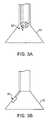
- FIGS. 4A and 4Bshow perspective and end views, respectively, of an imaging hood having at least one layer of a transparent elastomeric membrane over the distal opening of the hood.
- FIGS. 5A and 5Bshow perspective and end views, respectively, of an imaging hood which includes a membrane with an aperture defined therethrough and a plurality of additional openings defined over the membrane surrounding the aperture.
- FIG. 6shows an assembly view of a visualization system configured for tissue ablation utilizing a bipolar electrode configuration.
- FIG. 7shows a side view of a visualization hood configured for tissue ablation utilizing a bipolar electrode configuration with a central electrode and a ring electrode.
- FIG. 8shows a side view of another variation where a transparent fluid may conduct the charge to or from a ring electrode.
- FIG. 9shows a side view of another variation where a transparent fluid may conduct the charge to or from a central electrode.
- FIG. 10shows a side view of another variation of a visualization hood having at least two chambers through which transparent fluid conducting a current may flow to effect tissue ablation.
- FIG. 11shows a side view of another variation where a current may be flowed through the transparent fluid flowing between co-axially overlapping hoods.
- FIG. 12Ashows a side view of another variation where an inflatable visualization balloon may have at least two chambers through which transparent fluid conducting a current may flow to effect tissue ablation.
- FIG. 12Bshows a side view of an inflatable visualization balloon having one or more ring electrodes ablating the underlying tissue while under visualization.
- FIG. 12Cshows a partial cross sectional side view of the visualization balloon having a porous contact surface and an ablation probe advanced through the balloon.
- FIGS. 12D and 12Eshow side views of another variation of a visualization balloon having an ablating ring electrode and which is expandable via mechanical activation in its low-profile and expanded configurations.
- FIG. 12Fshows a side view of another variation of a visualization balloon having ablation electrodes on the distal front surface of the imaging balloon.
- FIG. 13Ashows a side view of another variation where a plurality of electrodes configured in a bipolar arrangement may be positioned along a distal membrane of the hood.
- FIGS. 13B and 13Cillustrate end views of electrode arrangement variations along the distal membrane.
- FIG. 13Dillustrates an end view of a concentric ring electrodes configured in a bipolar electrode arrangement.
- FIG. 14Ashows a side view of another variation where one or more support struts serve as electrodes.
- FIG. 14Bshows a side view of the variation of FIG. 14A ablating tissue via the one or more support struts.
- FIG. 14Cshows a side view of a visualization hood ablating tissue via energy conducted through the transparent fluid between an electrode within the hood and one or more support struts serving as electrodes.
- FIG. 15shows a side view of another variation where tissue drawn partially into the hood through the aperture is ablated between electrodes.
- FIG. 16Ashows a side view of another variation where tissue drawn between at least two separate chambers may be ablated as current is conducted therebetween.
- FIG. 16Bshows a side view of another variation where the visualization balloon may enclose a working space within which tissue may be ablated.
- FIG. 16Cshows a side view of another variation where an ablation probe may be advanced through a working lumen into contact against tissue bounded within a working space.
- FIG. 17shows a side view of another variation where tissue drawn between two separate chambers via a tissue grasper may be ablated therebetween.
- FIG. 18shows a side view of another variation where tissue adhered to a tissue grasping instrument may be ablated through the instrument.
- FIG. 19shows a side view of another variation where a tissue grasper having at least two grasping members may ablate the tissue.
- FIG. 20shows a side view of another variation where one or more distally projecting struts may be employed as electrodes.
- FIG. 21shows a side view of another variation where one or more distally projecting conducting wires may be employed as electrodes.
- FIG. 22shows a side view of another variation where one or more distally extendable members may be employed as electrodes.
- FIG. 23shows a side view of another variation where a distally projecting needle may be employed as an electrode for tissue ablation.
- FIG. 24shows a side view of another variation where a distally projecting needle may be employed with a ring electrode for tissue ablation.
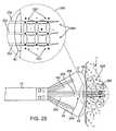
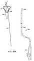
- FIG. 25shows a side view and a detail view of a multiple needle assembly having an arrangement of electrodes along the needle body.
- FIG. 26shows a side view of a another variation where a distally protruding anchor member may be utilized as an electrode for tissue ablation.
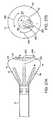
- FIGS. 27A and 27Bshow side and end views, respectively, of a rotatable member utilized as an electrode for bipolar ablation.
- FIG. 27Cshows a perspective view of a tissue visualization hood defining an expandable aperture over its distal membrane.
- FIG. 27Dshows a side view of the apparatus of FIG. 27C having an ablation probe advanced distally through the expandable aperture.
- FIG. 28shows a side view of another variation where hyposaline or chilled saline may be used to reduce or control the conductivity of the fluid for tissue ablation.
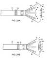
- FIGS. 29A and 29Bshow side views of a return electrode positioned optionally along the deployment catheter shaft and the sheath, respectively.
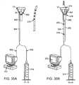
- FIG. 30illustrates a visualization catheter positioned transseptally within a left atrium where a return electrode is positioned along the sheath proximate to the atrial septum.
- FIG. 31illustrates a visualization catheter where a return electrode is positioned external to the atrial chamber along an epicardial surface.
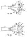
- FIG. 32illustrates a visualization catheter where a return electrode may be configured as a basket deployed in proximity to the hood.
- FIG. 33Ashows a partial cross-sectional side view of a visualization balloon which is configured to ablate contacted tissue through capacitive coupling while under visualization.
- FIG. 33Bshows a schematic of the electrical coupling when capacitively coupled to tissue.
- FIGS. 34A and 34Bshow perspective views of another variation of a tissue visualization and ablation balloon system where individual balloons are inflatable at variable rates to articulate an imaging element within the device.
- FIG. 35Ashows a representative assembly view of another variation of an imaging and ablation system which is removably attachable onto a separate instrument.
- FIG. 35Bshows an example of an assembled imaging and ablation system where the removable assembly is attached to an ablation probe.
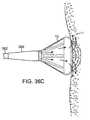
- FIG. 36Ashows a representative assembly view of another variation where a removably attachable imaging and ablation system may be coupled to an endoscope.
- FIGS. 36B and 36Cshow an example of the assembled imaging and ablation system and the system utilized to visualize and ablate underlying tissue, respectively.
- FIGS. 37A and 37Bshow side views of an articulatable ablation catheter and a tissue visualization catheter, respectively, which may be passively articulated.
- FIGS. 37C and 37Dshow perspective views of the tissue visualization catheter passively steered by the ablation catheter positioned therethrough.
- a tissue-imaging and manipulation apparatus described hereinis able to provide real-time images in vivo of tissue regions within a body lumen such as a heart, which is filled with blood flowing dynamically therethrough and is also able to provide intravascular tools and instruments for performing various procedures upon the imaged tissue regions.
- Such an apparatusmay be utilized for many procedures, e.g., facilitating transseptal access to the left atrium, cannulating the coronary sinus, diagnosis of valve regurgitation/stenosis, valvuloplasty, atrial appendage closure, arrhythmogenic focus ablation, among other procedures.
- tissue imaging and manipulation assembly 10may be delivered intravascularly through the patient's body in a low-profile configuration via a delivery catheter or sheath 14 .
- tissue imaging and manipulation assembly 10may be delivered intravascularly through the patient's body in a low-profile configuration via a delivery catheter or sheath 14 .
- tissue imaging and manipulation assembly 10may be delivered intravascularly through the patient's body in a low-profile configuration via a delivery catheter or sheath 14 .
- tissue imaging and manipulation assembly 10may be delivered intravascularly through the patient's body in a low-profile configuration via a delivery catheter or sheath 14 .
- a transseptal procedure or septostomyTo non-operatively effect such access, one conventional approach involves puncturing the intra-atrial septum from the right atrial chamber to the left atrial chamber in a procedure commonly called a transseptal procedure or septostomy.
- imaging hood 12When the imaging and manipulation assembly 10 is ready to be utilized for imaging tissue, imaging hood 12 may be advanced relative to catheter 14 and deployed from a distal opening of catheter 14 , as shown by the arrow. Upon deployment, imaging hood 12 may be unconstrained to expand or open into a deployed imaging configuration, as shown in FIG. 1B .
- Imaging hood 12may be fabricated from a variety of pliable or conformable biocompatible material including but not limited to, e.g., polymeric, plastic, or woven materials.
- a woven materialis Kevlar® (E.I.
- imaging hood 12may be fabricated from a translucent or opaque material and in a variety of different colors to optimize or attenuate any reflected lighting from surrounding fluids or structures, i.e., anatomical or mechanical structures or instruments. In either case, imaging hood 12 may be fabricated into a uniform structure or a scaffold-supported structure, in which case a scaffold made of a shape memory alloy, such as Nitinol, or a spring steel, or plastic, etc., may be fabricated and covered with the polymeric, plastic, or woven material.
- a shape memory alloysuch as Nitinol, or a spring steel, or plastic, etc.
- imaging hood 12may comprise any of a wide variety of barriers or membrane structures, as may generally be used to localize displacement of blood or the like from a selected volume of a body lumen or heart chamber.
- a volume within an inner surface 13 of imaging hood 12will be significantly less than a volume of the hood 12 between inner surface 13 and outer surface 1 .
- Imaging hood 12may be attached at interface 24 to a deployment catheter 16 which may be translated independently of deployment catheter or sheath 14 . Attachment of interface 24 may be accomplished through any number of conventional methods.
- Deployment catheter 16may define a fluid delivery lumen 18 as well as an imaging lumen 20 within which an optical imaging fiber or assembly may be disposed for imaging tissue.
- imaging hood 12When deployed, imaging hood 12 may expand into any number of shapes, e.g., cylindrical, conical as shown, semi-spherical, etc., provided that an open area or field 26 is defined by imaging hood 12 . The open area 26 is the area within which the tissue region of interest may be imaged.
- Imaging hood 12may also define an atraumatic contact lip or edge 22 for placement or abutment against the tissue region of interest.
- the diameter of imaging hood 12 at its maximum fully deployed diameteris typically greater relative to a diameter of the deployment catheter 16 (although a diameter of contact lip or edge 22 may be made to have a smaller or equal diameter of deployment catheter 16 ).
- the contact edge diametermay range anywhere from 1 to 5 times (or even greater, as practicable) a diameter of deployment catheter 16 .
- FIG. 1Cshows an end view of the imaging hood 12 in its deployed configuration. Also shown are the contact lip or edge 22 and fluid delivery lumen 18 and imaging lumen 20 .
- deployment catheter 16may be manipulated to position deployed imaging hood 12 against or near the underlying tissue region of interest to be imaged, in this example a portion of annulus A of mitral valve MV within the left atrial chamber.
- the translucent fluid 28such as saline, may then be pumped through fluid delivery lumen 18 , intermittently or continuously, until the blood 30 is at least partially, and preferably completely, displaced from within open area 26 by fluid 28 , as shown in FIG. 2B .
- contact edge 22need not directly contact the underlying tissue, it is at least preferably brought into close proximity to the tissue such that the flow of clear fluid 28 from open area 26 may be maintained to inhibit significant backflow of blood 30 back into open area 26 .
- Contact edge 22may also be made of a soft elastomeric material such as certain soft grades of silicone or polyurethane, as typically known, to help contact edge 22 conform to an uneven or rough underlying anatomical tissue surface.
- the fluid 28may be pumped temporarily or sporadically only until a clear view of the tissue is available to be imaged and recorded, at which point the fluid flow 28 may cease and blood 30 may be allowed to seep or flow back into imaging hood 12 . This process may be repeated a number of times at the same tissue region or at multiple tissue regions.
- FIG. 3Ashows a partial cross-sectional view of an example where one or more optical fiber bundles 32 may be positioned within the catheter and within imaging hood 12 to provide direct in-line imaging of the open area within hood 12 .
- FIG. 3Bshows another example where an imaging element 34 (e.g., CCD or CMOS electronic imager) may be placed along an interior surface of imaging hood 12 to provide imaging of the open area such that the imaging element 34 is off-axis relative to a longitudinal axis of the hood 12 , as described in further detail below.
- the off-axis position of element 34may provide for direct visualization and uninhibited access by instruments from the catheter to the underlying tissue during treatment.
- the hood 12may have an open field which is uncovered and clear to provide direct tissue contact between the hood interior and the underlying tissue to effect any number of treatments upon the tissue, as described above. Yet in additional variations, imaging hood 12 may utilize other configurations. An additional variation of the imaging hood 12 is shown in the perspective and end views, respectively, of FIGS. 4A and 4B , where imaging hood 12 includes at least one layer of a transparent elastomeric membrane 40 over the distal opening of hood 12 .
- An aperture 42 having a diameter which is less than a diameter of the outer lip of imaging hood 12may be defined over the center of membrane 40 where a longitudinal axis of the hood intersects the membrane such that the interior of hood 12 remains open and in fluid communication with the environment external to hood 12 .
- aperture 42may be sized, e.g., between 1 to 2 mm or more in diameter and membrane 40 can be made from any number of transparent elastomers such as silicone, polyurethane, latex, etc. such that contacted tissue may also be visualized through membrane 40 as well as through aperture 42 .
- Aperture 42may function generally as a restricting passageway to reduce the rate of fluid out-flow from the hood 12 when the interior of the hood 12 is infused with the clear fluid through which underlying tissue regions may be visualized. Aside from restricting out-flow of clear fluid from within hood 12 , aperture 42 may also restrict external surrounding fluids from entering hood 12 too rapidly. The reduction in the rate of fluid out-flow from the hood and blood in-flow into the hood may improve visualization conditions as hood 12 may be more readily filled with transparent fluid rather than being filled by opaque blood which may obstruct direct visualization by the visualization instruments.
- aperture 42may be aligned with catheter 16 such that any instruments (e.g., piercing instruments, guidewires, tissue engagers, etc.) that are advanced into the hood interior may directly access the underlying tissue uninhibited or unrestricted for treatment through aperture 42 .
- instruments passed through catheter 16may still access the underlying tissue by simply piercing through membrane 40 .
- FIGS. 5A and 5Bshow perspective and end views, respectively, of imaging hood 12 which includes membrane 40 with aperture 42 defined therethrough, as described above.
- This variationincludes a plurality of additional openings 44 defined over membrane 40 surrounding aperture 42 .
- Additional openings 44may be uniformly sized, e.g., each less than 1 mm in diameter, to allow for the out-flow of the translucent fluid therethrough when in contact against the tissue surface.
- openings 44are illustrated as uniform in size, the openings may be varied in size and their placement may also be non-uniform or random over membrane 40 rather than uniformly positioned about aperture 42 in FIG. 5B .
- there are eight openings 44 shown in the figuresalthough fewer than eight or more than eight openings 44 may also be utilized over membrane 40 .
- ablative systemstypically employ electrodes arranged in a monopolar configuration where a single electrode is positioned proximate to or directly against the tissue to be treated within the patient body and a return electrode is located external to the patient body.
- the assembly illustrated in FIG. 6shows an example of a tissue visualization system which is configured with electrodes arranged in a bipolar configuration where the electrode and return electrode are arranged in proximity to the tissue region to be treated and visualized.
- bipolar electrode ablationremoves the need for a return or grounding electrode to be adhered to the skin of the patient and may further allow for a more precise delivery of ablation energy over a small target area for creation of precise lesions.
- such assemblies, apparatus, and methodsmay be utilized for treatment of various conditions, e.g., arrhythmias, through ablation under direct visualization. Details of examples for the treatment of arrhythmias under direct visualization which may be utilized with apparatus and methods described herein are described, for example, in U.S. patent application Ser. No. 11/775,819 filed Jul. 10, 2007 (U.S. Pat. Pub. No. 2008/0015569 A1), which is incorporated herein by reference in its entirety.
- Variations of the tissue imaging and manipulation apparatusmay be configured to facilitate the application of bipolar energy delivery, such as radio-frequency (RF) ablation, to an underlying target tissue for treatment in a controlled manner while directly visualizing the tissue during the bipolar ablation process as well as confirming (visually and otherwise) appropriate treatment thereafter.
- bipolar energy deliverysuch as radio-frequency (RF) ablation
- bipolar ablation and visualization catheter assembly 50illustrates one variation where the visualization hood 12 may incorporate a bipolar ablation assembly 52 within and/or along the hood 12 .
- the assembly 50is further illustrated where bipolar ablation assembly 52 may be coupled or otherwise in electrical communication with power generator 56 (e.g., RF power generator) through deployment catheter 16 and handle 54 via cable 58 .
- Fluid reservoir 60is also illustrated as being coupled to handle 54 and in fluid communication with hood 12 as well as image display assembly 62 which may be coupled to an optical fiber bundle or to an electronic imaging sensor (e.g., CCD or CMOS imager) positioned within or along hood 12 for visualizing the underlying tissue, as described above.
- Bipolar ablation assembly 52may be configured in a number of different arrangements to effect bipolar ablation of the underlying tissue.
- FIG. 7illustrates hood 12 having a number of longitudinally oriented support struts 70 therealong and membrane 40 defining aperture 42 over a distal end of hood 12 .
- Imaging element 34may be positioned along an inner surface of hood 12 to provide imaging the underlying tissue.
- an electrode 72may extend from catheter 16 via electrode support member 74 and positioned within hood 12 , e.g., positioned near or along a central axis of aperture 42 and proximate to or through aperture 42 .
- An electrically conductive electrode ring 76may be positioned along the membrane 40 and enclose aperture 42 .
- the electrically conductive central 72 and ring electrode 76may be made from a number of bio-inert materials such as, though not limited to, stainless stain, silver, gold, platinum, etc.
- electrodes 72 , 76may be connected by conductive wires which are insulated by a thin layer of insulation such as PET, latex or other biocompatible polymers.
- the visualization hood 12is placed against or adjacent to a region of tissue T to be imaged and/or ablated in a body lumen that is normally filled with opaque bodily fluids such as blood.
- Translucent or transparent fluids 78which are also electrically conductive, such as saline, may be then introduced into the imaging hood 12 until the transparent fluid 78 displaces the blood thus leaving a clear region of tissue T to be imaged via the imaging element 34 before an ablation process.
- RF energymay be generated from power generator 56 such that ablation energy 80 is conducted between central electrode 72 and ring electrode 76 via the saline fluid 78 flowing therebetween in effect ablating the underlying tissue.
- the saline fluid 78 purged from hood 12 and out through aperture 42may thus serve multiple functions of clearing blood for visualization, conducting ablative energy, as well as optionally cooling the ablated tissue region to prevent tissue charring, desiccation, or other endothelial disruptions such as “tissue popping”.
- Other examples of utilizing energy conductive fluid for tissue visualization and ablationare described in further detail in U.S. patent application Ser. No. 12/118,439 filed May 9, 2008 as well as U.S. Prov Pat. App. No. 60/917,487 filed May 11, 2007, each of which is incorporated herein by reference in its entirety.
- FIG. 8shows hood 12 having ring electrode 76 positioned on membrane 40 and serving as the return electrode.
- RF energymay be conducted through saline 78 between one or more electrically charged support struts 70 , which may have one or more portions 82 exposed along an inner surface of hood 12 in contact with the introduced saline 78 , and ring electrode 76 .
- the ablation energyis conducted through the saline fluid 78 from the exposed electrode portions 82 and to the return ring electrode 76 .
- FIG. 9shows an example where a centrally positioned electrode 72 may be placed near or at aperture 42 , as described above, and instead of utilizing a ring electrode, energy may be conducted through the saline fluid 78 between the exposed portions 82 of electrically charged support struts 70 and electrode 72 to ablate the underlying tissue.
- electrode 72may be comprised at least in part by a transparent casing, e.g., polycarbonate polymers.
- FIG. 10illustrates a side view of another bipolar electrode arrangement variation where hood 12 may be internally segmented into two or more separated chambers where saline fluid having opposite charges may be introduced into each respective chamber for bipolar ablation.
- hood 12may have first chamber 92 and second chamber 94 divided by septum 90 , which may be fabricated from the same material as hood 12 or any other number of electrically non-conductive transparent medical-grade materials, e.g., ChronoFlexTM, such that both chambers and the underlying tissue may be visualized via imaging element 34 .
- Each chamber 92 , 94may define a corresponding first and second aperture 96 , 98 over the distal membrane and may also each have a corresponding first and second electrode 100 , 104 positioned within each respective chamber 92 , 94 .
- Each electrodemay be positioned within the chambers via respective first and second electrode support members 102 , 106 .
- the transparent fluidmay be introduced into each chamber 92 , 94 past the electrodes 100 , 104 such that the charged fluid 108 , 110 passing through their respective apertures 96 , 98 may contact one another over the tissue to conduct energy 112 therebetween and ablate the underlying tissue.
- FIG. 11shows a side view of a hood 12 having a second smaller inner hood 124 positioned within the interior of hood 12 .
- the conductive fluid 120may be infused into the interior of hood 12 past one or more conductive electrodes 100 , 104 and over inner hood 124 and distally through the hood aperture. Fluid may be infused through an inner fluid lumen 122 containing a return electrode such that the fluid 126 infused through lumen 122 and into inner hood 124 may contact the charged fluid introduced into hood 12 .
- the underlying tissuemay be ablated by the energy conducted through the fluid.
- additional inner hood structuresmay also be contained by the outer hood for bipolar electrode ablation.
- FIG. 12Ashows a side view of another variation where hood 12 is replaced by an expandable balloon 130 which may be inflated by the transparent fluid.
- the balloon 130may be fabricated from a transparent material to allow for visualization of contacted tissue underlying the balloon 130 by an imaging element 132 positioned within the balloon 130 .
- a balloon support member 134may extend through the balloon from deployment catheter 16 to a distal end of the balloon 130 to provide structural integrity.
- support member 134can be made from a transparent material, such as polycarbonate, PVC, silicone, etc., in order to provide for unobstructed visualization.
- the balloon 130may itself be divided into two or more separate chambers each defining a respective first and second aperture 136 , 138 near a distal end of balloon 130 .
- a first and second electrode 100 , 104may be positioned such that the conductive fluid 140 , 142 flowing past each respective electrode may conduct ablation energy 144 between the electrodes 100 , 104 via the conductive fluid when flowed out of the respective apertures 136 , 138 and into contact with the underlying tissue T.
- imaging element 132can be deployed from a work channel defined in support member 134 to visualize the ablated site throughout the ablation procedure.
- FIG. 12Bshows a side view of yet another variation where expandable balloon 130 may have support member 134 define a fluid lumen 146 therethrough.
- the distal end of lumen 146 which contacts against the tissue surfacemay define one or more ring electrodes 148 surrounding the opening of lumen 146 for ablating the underlying tissue.
- a return/ground electrodee.g., grounding pad
- FIG. 12Cshows a side view of another variation where ablation probe 141 may be advanced through the support member 134 lumen and advanced into, e.g., a vessel lumen VL, to contact and ablate the tissue surrounding the vessel opening.
- the distal surface of the balloon 130may optionally define a plurality of holes, slits, openings, or apertures (e.g., micro-holes) that allow the purging saline fluid to seep through the balloon membrane.
- the balloon 130may facilitate cooling of the ablated tissue and increase flow and efficiency of saline purged and may also function to increase the tissue surface subjected to ablation.
- FIGS. 12D and 12Eshow side views of yet another variation where the visualization balloon 130 may be expanded or deployed by mechanical actuation either alone or in combination with fluid inflation from a low profile delivery shape to an expanded deployment shape, as shown.
- This particular variationillustrates a number of reconfigurable support members 143 configured as a scaffold or reconfigurable basket frame which is attached along the deployment catheter 16 and at attachment point 145 at a distal end of support member 134 .
- the support members 143may be made from a shape memory alloy such as Nitinol and may be passively stored in its delivery configuration by compressing the balloon and frame into a sheath. Upon deployment from the sheath, the balloon 130 and/or support members 143 may self-expand.
- the support members 143may be made from non-shape memory materials such as stainless steel, tungsten, Elgiloy®, etc. and be actively deployed into its expanded configuration, e.g., compressing the frame longitudinally, or by other push mechanisms known to those skilled in the art.
- ring electrodes 148can be attached on the distal circumference of the work channel 134 that is exposed and in contact with imaged tissue. The electrodes 148 can also be used for ablating and/or detecting electrophysiological signals of contacted imaged tissue.
- electrodes 147 positioned circumferentially about the work channelcan also be used for mapping and pacing of electrophysiological signals of tissue in contact with the electrodes. As shown, the electrodes 147 may be alternatively arranged over a distal exterior face of the imaging balloon 130 .
- FIG. 13Ashows a side view of yet another variation where the distal membrane 40 of hood 12 may have multiple conducting electrodes 150 and return electrodes 152 directly upon the face of membrane 40 for contact against the underlying tissue.
- the shape and size of the formed lesionscan be controlled by the arrangement of bipolar electrodes across the hood membrane 40 .
- oppositely charged electrodes 150 , 152may be placed adjacent to each other in an alternating circumferential pattern over membrane 40 .
- similarly charged electrodes 150 , 152may be grouped together in a circumferential pattern over membrane 40 . Such an arrangement may result in the formation of linear lesions which is normally desirable in ablation procedures.
- FIG. 13DAnother bipolar electrode arrangement is shown in the end view of FIG. 13D , which shows a conducting electrode ring 154 and a return electrode ring 156 arranged in a concentric pattern with respect to the aperture over the face of membrane 40 .
- the flow of current passing between these oppositely charged rings 154 , 156may aid in the formation of lesions in the tissue region within the periphery of these ring electrodes.
- the flow rate of the salinecan be regulated from the proximal end of the catheter system if so desired.
- FIG. 14Ashows a side view of another variation where one or more electrically conductive support struts 160 may be function as an electrode to conduct electricity to one or more corresponding return electrode support strut 162 .
- These electrode support struts 160 , 162may be positioned along hood 12 such that they are exposed exteriorly along an outer surface of hood 12 .
- the conductive fluid 164 flowing through hood 12may flow out of the aperture and around the electrode struts such that energy is conducted between the struts 160 , 162 .
- the hood outer surfacemay be utilized to contact and ablate underlying tissue, as illustrated in the side view of FIG. 14B .
- the flow of ablation energy 166 through the electrically charged fluid 164 between the struts 160 , 162may result in the formation of lesions on the tissue region under the base of the hood 12 as well as along the side surfaces of the hood 12 .
- an electrode 100may be positioned within hood 12 such that the flow of conducting fluid 164 past the electrode 100 may conduct ablation energy when contacted against one or more support struts 160 configured as a return electrode to ablate the underlying tissue T.
- the conducting saline fluid 164may not only purge the hood 12 of blood to facilitate visualization of the underlying tissue but may also be used to potentially cool the ablation area and ensure the formation of uniform lesions on the tissue regions T.
- FIG. 15illustrates a side view of another variation where a portion of tissue 176 under visualization through hood 12 may be drawn at least partially into the interior of hood 12 through aperture 42 by back-flowing the transparent fluid 174 back through a fluid lumen in deployment catheter 16 .
- At least one conducting electrode 170 and at least one return electrode 172may be positioned about the hood aperture 42 such that the tissue 176 pulled into the hood 12 may be subjected to ablation energy conducted between the two electrodes 170 , 172 while under direct visualization from imaging element 34 .
- Such an electrode arrangementmay enable lesion formation across the entire depth of tissue 176 in a more efficient and predictable manner as compared to surface ablation.
- FIG. 16Aillustrates another variation also utilizing suction where hood 12 may be segmented into at least two chambers where each chamber defines a respective aperture 96 , 98 , as previously described.
- the targeted tissue Tmay be adhered via back-flowed saline or via a separate suction lumen 180 to pull a portion of tissue 176 into a working space or theater 182 defined between the apertures 96 , 98 .
- Ablation energy 184may be subsequently conducted through the saline fluid between the respective electrodes 100 , 104 positioned within each chamber such that the adhered tissue 176 is ablated through its thickness as well as the underlying tissue T.
- FIG. 16Billustrates another variation where the expandable member or hood may have a working space or theater 182 defined within in communication with a working channel 186 .
- An electrodemay be positioned within the working channel 186 and terminated where the distal end of the electrode is proximity to tissue and in contact with the conductive fluid purged from the work channel.
- the body of the energy delivery wirecan be insulated by a thin layer of insulation such as PET or other biocompatible polymers.
- the electrodemay comprise an exposed electrically conductive probe that can be made from or plated with conductive materials such as stainless stain, Nitinol, copper, silver, gold, or platinum, etc. Saline enclosed within the work space 182 can be energized to ablate the underlying tissue.
- FIG. 16Cshows another variation where ablation may be subsequently performed with an ablation catheter 141 , such as RF catheter, on the tissue surface with the purged saline serving multiple functions of visualization, cooling, and conductive medium for creating relatively larger lesions.
- an ablation catheter 141such as RF catheter
- FIG. 17shows a side view of yet another variation where hood 12 may be replaced by a toroidal balloon 190 which may be fabricated from a transparent material, as previously described.
- Toroidal balloon 190may be tapered to extend radially away from catheter 16 while defining a working space or theater 192 within the balloon interior.
- a tissue grasper 196e.g., helical grasper, extending from an instrument shaft 194 may be translatable through catheter 16 and working space 192 such that tissue to be ablated may be engaged by the grasper 196 and pulled proximally into working space 192 .
- the grasped tissue 198may be brought into contact against electrodes 96 , 98 positioned about the working space 192 along balloon 190 such that ablation may be effected upon the tissue.
- FIG. 18Another variation is shown in the side view of FIG. 18 , which shows a tissue grasper 196 engaging and pulling a portion of tissue 198 to be ablated at least partially into the hood 12 through aperture 42 .
- grasper 196may be configured as an electrode such that ablation energy may be conducted between the grasper 196 and electrode 100 via the saline fluid and through the grasped tissue 198 .
- FIG. 19shows another variation in the side view of an imaging hood 12 having an instrument shaft 194 with a tissue grasper 200 having at least two members configured for engaging tissue and also for functioning as electrodes in a bipolar arrangement.
- the mechanical action of the grasper 200enables the engagement of a tissue fold through which ablation energy may be conducted.
- the members of grasper 200can be manipulated by applying a push or pull force at the proximal end of the catheter.
- FIG. 20shows yet another variation in a side view of an assembly which may be used to controllably form lesions which are relatively wider than an area of the hood distal membrane 40 .
- One or more electrically conductive struts 210may have a projecting portion 212 extending distally at an angle from hood 12 and terminating at a conducting tip 214 which may be optionally tapered into a needle-like tissue piercing tip.
- the one or more conducting tips 214may be extended distally into the tissue region surrounding the hood 12 contacted against the tissue surface and the conducting fluid may be infused into hood 12 past electrode 100 and through aperture 42 and into the area immediately surrounding hood 12 .
- the ablation energymay be thus conducted between electrode 100 and the one or more conducting tips 214 via the fluid to ablate the tissue therebetween.
- the conducting tips 214 extended by the projecting portions 212may thus result in effective and relatively deeper transmural ablation of the tissue area not only directly beneath hood 12 but also the tissue surrounding the hood 12 .
- FIG. 21shows a side view of an alternative variation where one or more conductive wires 220 may extend distally past hood 12 from attachment points 222 located proximal to hood 12 .
- the one or more conductive wires 220may extend linearly or in an arcuate manner distal to hood 12 such that when hood 12 is positioned against a tissue region to be treated, the conductive wires 220 contact the tissue region surrounding the hood 12 to create a lesion pattern extending beyond the hood 12 .
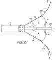
- FIG. 22shows yet another alternative utilizing one or more distally extendable conducting struts 230 which may be extended from hood 12 such that the struts 230 curve and extend radially from hood 12 within a plane formed by the distal membrane of hood 12 .
- the extendable struts 230may function as return electrodes for the ablation energy conducted from electrode 100 within hood 12 via the conductive transparent fluid flowing through the aperture. Depending upon the size of desired lesion, the distance which the struts 230 extend from hood 12 can be controlled.
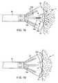
- FIG. 23depicts a side view of another variation where a transmural needle tip advanceable through hood 12 and into underlying tissue T may be used as a return electrode to create relatively deeper lesions.
- Needle support member 240may comprise a piercing conductive needle tip 242 which may be advanced through aperture 42 and into the underlying visualized tissue. With electrode needle tip 242 inserted at a predetermined depth into the tissue T, ablation energy 244 may be conducted through the saline between electrode 100 and needle tip 242 to ablate the tissue T transmurally.
- FIG. 24shows an alternative variation where an electrode ring 246 may be positioned along the membrane 40 in contact against the tissue surface such that the ablation energy 244 is conducted between electrode ring 246 and needle tip 242 positioned within the tissue T.
- the conductive saline fluid introduced into the hood 12may thus serve in aiding in visualization of the tissue, optionally cooling of the tissue region being ablated, and may also serve as a transparent electrode for bipolar electrode ablation between the tissue in contact with the saline and the transmural needle tip 242 penetrated subsurface to the ablation site.
- FIG. 25shows yet another alternative variation where ablation needle assembly 250 having a number of needles 252 , 254 , 256 (e.g., three in this example although two needles or four or more may also be utilized, as practicable) may be advanced through hood 12 and into the underlying tissue T while positioned adjacent to one another.
- Each of the needlesmay have a distal portion, as illustrated in ablation tip detail 258 , which comprises a plurality of exposed electrodes 262 at or proximal to the needle tips 264 .
- energymay be conducted between the exposed electrodes 262 along needle assembly 250 to ablate 260 the tissue T surrounding the needles.
- FIG. 26shows yet another example in the side view illustrating hood 12 utilized with an anchoring member 272 , e.g., a helical anchor, extendable via an instrument support member 270 which may also be configured as an electrode.
- anchoring member 272may be comprised of a wire member made of gold or silver coated Nitinol. Examples of helical anchoring members and methods of use are described in further detail in U.S. patent application Ser. No. 11/959,158 filed Dec. 18, 2007 and U.S. Prov. Pat. App. 60/870,598 filed Dec. 18, 2006, each of which is incorporated herein by reference in its entirety.
- anchoring member 272may be advanced in a low-profile into a vessel lumen 276 , such as a lumen of a pulmonary vein, and expanded to temporarily engage the vessel walls.
- the circumference of membrane 40 in contact against the lumen ostiummay comprise one or more return electrodes 274 such that when the electrodes are energized, current may flow between the electrodes via the saline fluid flowing past to ablate the surrounding tissue region T while under direct visualization, e.g., via imaging element 34 .
- FIGS. 27A and 27Bshow side and end views, respectively, of another variation where current may flow between an ablation instrument extending through hood 12 having an electrode support member 280 with an angled portion 282 and at least one conducting electrode 284 positioned near or at a distal end thereof.
- Electrode 284may be rotatable about a longitudinal axis of support member 280 , as indicated by the direction of rotation 286 , to facilitate placement of the electrode 284 over the underlying visualized tissue for optimizing ablation.
- One or more support struts along hood 12may be configured as an electrode such that the ablation current may be conducted through the saline fluid between electrode 284 and the one or more electrodes of the support struts.
- FIGS. 27C and 27Dshow perspective and side views of yet another variation where hood 12 may define a distal membrane 281 , as previously described, which defines an expandable aperture 283 , where in this example, may define a multi-slit opening which is sized to narrowly allow for the passage of an instrument therethrough (such as an ablation catheter 285 .
- an instrument therethroughsuch as an ablation catheter 285 .
- the catheter 285may have a circulating coolant 287 flowing through in a circulating flow pattern.
- the catheter in this examplemay include a 7 Fr, 4 mm electrode having a fluid of 5% dextrose circulating at 36 ml/min therethrough.
- a thermocouple 289may be positioned within for detecting the electrode temperature.
- the cathetermay define an infusion lumen 291 through which a cooling fluid 293 (e.g., a 7.5 Fr, 3.5 mm electrode with 0.9% NaCl saline infusion) may be flowed through.
- a cooling fluid 293e.g., a 7.5 Fr, 3.5 mm electrode with 0.9% NaCl saline infusion
- the electrode distal endmay define one or more irrigation lumens 295 through which the cooling fluid may be infused for contacting the underlying tissue (e.g., 6 irrigation holes each having a 0.4 mm diameter).
- ablation cathetersmay include, though not limited to, commercially available instruments such as the THERMOCOOL® Irrigated tip catheter (Biosense Webster, Inc.), Chilli IITM Cooled Ablation Catheter Boston Scientific, Inc.), or the Cool PathTM Irrigated Tip Ablation Catheter (St. Jude, Inc.).
- Other configurationsmay alternatively include the use of a one-way valve in place of the aperture 283 and the use of multiple circumferential balloons attached on the inner wall of the hood inflated around the ablation catheter to isolate saline from ablated tissue.
- FIG. 28shows a side view of yet another variation where hood 12 may be configured with electrode 292 , 294 arranged over the membrane 40 , as previously described.
- the salinity and/or temperature of the saline fluidmay be controlled or altered to affect the conductivity of the saline fluid.
- a transparent fluid 290 having its salinity alterede.g., hyposaline fluid having a salt concentration less than 0.9%) may be introduced through hood 12 to reduce the conductivity of the fluid 290 and to accordingly adjust the ablation energy 296 through the tissue T.
- a temperature of the fluid 290may also be altered to further control a conductivity of the fluid (e.g., saline fluid having a temperature of 20° C.).
- a hyposaline fluid 290(and/or optionally reduced in temperature relative to body temperature) may reduce the conductivity of the surface of the ablated tissue region to potentially increase the depth of the ablated lesion as higher power and/or longer ablation durations can be applied without charring, desiccating, or causing endothelial disruption to the tissue surface. This can be applied with both monopolar and bipolar electrode arrangements.
- FIGS. 29A and 29Bshow side views of additional variations where a return electrode may be positioned externally and proximally to hood 12 .
- return electrode 300may be positioned proximal to hood 12 along a portion of the deployment catheter 16 while in the example of FIG. 29B , return electrode 300 may be positioned proximal to hood 12 along the outer sheath 14 , in which case a position of the electrode 300 may be adjusted by movement of the sheath 14 and/or catheter 16 relative to one another.
- the example in FIG. 29Balso illustrates the use of an electrode ring 302 positioned about aperture 42 over membrane 40 , although other electrode variations may be utilized.
- FIG. 30illustrates one example of use in a patient heart H
- the electrode 300positioned in this example along outer sheath 14
- the devicemay be advanced intravascularly, e.g., through the inferior vena cava IVC and the right atrium RA.
- the superior vena cava SVCis also illustrated for reference.
- a position of the electrode 300may be optionally maintained relative to the atrial septum AS via one or more stabilizing balloons 310 , 312 inflated on one or both sides of the septum.
- Electrode 300may thus serve as a return electrode for ablation via an electrode positioned within or along hood 12 , as previously described.
- hood 12may be advanced within the patient heart H as previously described, yet an electrode catheter 320 having a return electrode 322 positioned therealong may be advanced as an instrument separate from the visualization assembly and positioned in proximity to the hood 12 .
- return electrode 322may be placed along an external surface of the patient heart H, e.g., along the epicardial wall via a thoracotomy or through a vessel within the heart in proximity to the ablation site, such as through the coronary sinus, pulmonary artery, superior vena cava, inferior vena cava, etc.
- FIG. 32shows another example where the hood 12 may be positioned, e.g., within the left atrium LA as previously described but with a return electrode 332 positioned intravascularly via a separate electrode catheter 330 such that the return electrode 332 is positioned endocardially.
- the return electrode 332may take the shape, in one example, of a shape memory expandable basket with a plurality of electrodes forming the frame of the basket, as shown.
- This electrode basketcan be made from a conductive material such as gold or silver-coated Nitinol.
- FIG. 33Ashows a partial cross-sectional side view of a visualization and ablation instrument which utilizes an inflatable balloon 340 which may capacitively couple through balloon 340 , which may comprise a transparent, electrically conductive, and non-porous shell which may contact against the tissue to be visualized and ablated.
- the balloonmay be fabricated from materials such as indium-tin oxide, elastomers embedded with carbon nano-tubes, or translucent firms with gold, silver or platinum coatings manufactured by the Spi-MetTM process (Spire Medical Inc.).
- balloon 340may be inflated by a transparent electrically conductive fluid, such as saline, from a collapsed configuration to an expanded configuration.
- a conducting electrode 342may be positioned within the balloon 340 and an imaging element 34 may also be positioned within the balloon 340 .
- the current conducted from the electrode 342 and carried through the saline fluidmay couple via ionic transport through the saline and the balloon 340 to capacitively couple to the contacted tissue for ablation.
- FIG. 33Billustrates a schematic 344 of the capacitive coupling which occurs to ablate the tissue where the resistance through the fluid and balloon 340 (R PATH ) may couple capacitively couple (C) to the tissue (R TISSUE ).
- FIGS. 34A and 34Billustrate an expandable balloon 350 having imaging element 34 positioned within and surrounded by multiple inflatable balloons 352 which are also contained within the expandable balloon 350 .
- the imaging element 34can be articulated to move its field of view 354 to different regions of the ablation site.
- the internal balloons used in this variationcan be made from transparent elastomeric materials to permit visualization through the imaging element 34 . Further examples of variable balloon inflation for controlling an instrument is described in further detail in 11/775,837 filed Jul. 10, 2007, which has been incorporated herein in its entirety.
- the tissue visualization and ablation systemmay be configured as an end effector assembly which may be attachable or coupled to any number of other instruments.
- FIG. 35Ashows hood 12 having imaging element 34 self-contained as a separate assembly with a wire and/or connector 364 bundle leading to an imaging element processor and/or display 372 via imaging element wires 366 and a purging fluid reservoir 374 via irrigation channel 368 .
- a hood attachment 360e.g., elastic band
- hood assemblymay be coupled to ablation probe 370 via attachment 360 such that the distal tip of probe 370 extends within and optionally beyond hood 12 .
- Wire and/or connector bundle 364may be attached to probe 370 along its length via one or more connectors or attachment bands 376 such that the ablation probe may be advanced along with the hood assembly.
- Hood 12may also optionally define a rapid exchange port 362 through which a guidewire 378 may be passed to facilitate use and advancement of the instrument within the patient body. Further details and examples of rapid exchange ports 362 and their methods of use are described in Ser. No. 11/961,950 filed Dec. 20, 2007, which is incorporated herein by reference in its entirety. In use, hood 12 may be utilized, as previously described for visualization, while its positioning and control may be provided by the ablation probe 370 .
- FIG. 36AAnother variation is shown in the pre-assembly side view of FIG. 36A and the assembled view of FIG. 36B which show a hood assembly, as described above, which may be incorporated with other instruments such as an endoscope 380 which may have an articulatable distal end 386 coupled to a handle 384 via shaft 382 .
- the imaging hood assemblycan be attached to the endoscope 380 by having attachment 360 affixed to the distal end 386 of the endoscope 380 , e.g., via usage of elastic bands, clamps, screws threads, slip-fit components, adhesive, sleeve couplers, etc.
- Saline or other transparent/translucent electrically conductive fluidcan be purged through the working channel of the endoscope 380 .
- Other instrumentscan also be advanced into the imaging hood via the working channel of the endoscope 380 .
- power generator 388may provided for generating the ablation energy as well as an image processor and/or display 390 for viewing images either from an imaging element contained within or along hood 12 and/or as provided directly by the endoscope 380 .
- the rapid exchange port 362 defined along hood 12can additionally serve as an alternative path for instruments which may not be able to be passed through the working lumens of the endoscope 380 , e.g., due to limited size of the lumen channel or the number of channels the endoscope can provide.
- FIG. 36Cshows a side view of the hood assembly positioned against a tissue region to be visualized and treated.
- Any number of energy modalitiesmay be utilized for ablating the underlying tissue (such as RF, cryo, laser, HIFU or other forms of energy) through the lumen of the endoscope 380 while under direct visualization.
- an energy delivery probemay be passed through the working channels of the endoscope 380 and brought in contact with the saline inside the hood 12 to deliver RF ablation energy through the fluid, as previously described.
- an articulatable ablation probe 370may be incorporated in a deployment catheter 400 having a flexible shaft and hood 12 positioned thereupon, as shown in FIG. 37B .
- the flexible segmentcan be constructed from relatively low durometer and/or transparent polymers such as silicone or thin-walled polyurethanes.
- the flexible segmentcan be constructed by wire frames with struts longitudinally arranged by thin wires (e.g., approximately 0.005′′ to 0.015′′) such as Nitinol, stainless stain, Elgiloy®, tungsten, etc.
- the ablation probe 370may be introduced through the passively steerable flexible shaft of catheter 400 such that articulation of the ablation probe 370 may be utilized to articulate a position of the hood 12 , as illustrated in the perspective views of FIGS. 37C and 37D .
Landscapes
- Health & Medical Sciences (AREA)
- Life Sciences & Earth Sciences (AREA)
- Surgery (AREA)
- Engineering & Computer Science (AREA)
- Plasma & Fusion (AREA)
- Medical Informatics (AREA)
- Otolaryngology (AREA)
- Physics & Mathematics (AREA)
- Cardiology (AREA)
- Biomedical Technology (AREA)
- Heart & Thoracic Surgery (AREA)
- Nuclear Medicine, Radiotherapy & Molecular Imaging (AREA)
- Molecular Biology (AREA)
- Animal Behavior & Ethology (AREA)
- General Health & Medical Sciences (AREA)
- Public Health (AREA)
- Veterinary Medicine (AREA)
- Surgical Instruments (AREA)
Abstract
Description
Claims (15)
Priority Applications (1)
| Application Number | Priority Date | Filing Date | Title |
|---|---|---|---|
| US12/209,057US8235985B2 (en) | 2007-08-31 | 2008-09-11 | Visualization and ablation system variations |
Applications Claiming Priority (4)
| Application Number | Priority Date | Filing Date | Title |
|---|---|---|---|
| US96951107P | 2007-08-31 | 2007-08-31 | |
| US97146207P | 2007-09-11 | 2007-09-11 | |
| US12/201,811US20090062790A1 (en) | 2007-08-31 | 2008-08-29 | Direct visualization bipolar ablation systems |
| US12/209,057US8235985B2 (en) | 2007-08-31 | 2008-09-11 | Visualization and ablation system variations |
Related Parent Applications (1)
| Application Number | Title | Priority Date | Filing Date |
|---|---|---|---|
| US12/201,811Continuation-In-PartUS20090062790A1 (en) | 2007-08-31 | 2008-08-29 | Direct visualization bipolar ablation systems |
Publications (2)
| Publication Number | Publication Date |
|---|---|
| US20090076498A1 US20090076498A1 (en) | 2009-03-19 |
| US8235985B2true US8235985B2 (en) | 2012-08-07 |
Family
ID=40455367
Family Applications (1)
| Application Number | Title | Priority Date | Filing Date |
|---|---|---|---|
| US12/209,057Active2031-02-24US8235985B2 (en) | 2007-08-31 | 2008-09-11 | Visualization and ablation system variations |
Country Status (1)
| Country | Link |
|---|---|
| US (1) | US8235985B2 (en) |
Cited By (31)
| Publication number | Priority date | Publication date | Assignee | Title |
|---|---|---|---|---|
| US20120289951A1 (en)* | 2011-05-12 | 2012-11-15 | Kassab Ghassan S | Systems and methods for cryoblation of a tissue |
| US20140358089A1 (en)* | 2013-06-04 | 2014-12-04 | Boston Scientific Scimed, Inc. | Vacuum-assisted pancreaticobiliary cannulation |
| US9014789B2 (en) | 2011-09-22 | 2015-04-21 | The George Washington University | Systems and methods for visualizing ablated tissue |
| US9084611B2 (en) | 2011-09-22 | 2015-07-21 | The George Washington University | Systems and methods for visualizing ablated tissue |
| US9101735B2 (en) | 2008-07-07 | 2015-08-11 | Intuitive Surgical Operations, Inc. | Catheter control systems |
| US9155452B2 (en) | 2007-04-27 | 2015-10-13 | Intuitive Surgical Operations, Inc. | Complex shape steerable tissue visualization and manipulation catheter |
| US9192287B2 (en) | 2005-10-25 | 2015-11-24 | Intuitive Surgical Operations, Inc. | Tissue visualization device and method variations |
| US9226648B2 (en) | 2006-12-21 | 2016-01-05 | Intuitive Surgical Operations, Inc. | Off-axis visualization systems |
| US9332893B2 (en) | 2005-02-02 | 2016-05-10 | Intuitive Surgical Operations, Inc. | Delivery of biological compounds to ischemic and/or infarcted tissue |
| US9456752B2 (en) | 2013-03-14 | 2016-10-04 | Aperture Diagnostics Ltd. | Full-field three-dimensional surface measurement |
| US9510732B2 (en) | 2005-10-25 | 2016-12-06 | Intuitive Surgical Operations, Inc. | Methods and apparatus for efficient purging |
| US9526401B2 (en) | 2005-02-02 | 2016-12-27 | Intuitive Surgical Operations, Inc. | Flow reduction hood systems |
| US10004388B2 (en) | 2006-09-01 | 2018-06-26 | Intuitive Surgical Operations, Inc. | Coronary sinus cannulation |
| US10064540B2 (en) | 2005-02-02 | 2018-09-04 | Intuitive Surgical Operations, Inc. | Visualization apparatus for transseptal access |
| US10070772B2 (en) | 2006-09-01 | 2018-09-11 | Intuitive Surgical Operations, Inc. | Precision control systems for tissue visualization and manipulation assemblies |
| US10092172B2 (en) | 2007-05-08 | 2018-10-09 | Intuitive Surgical Operations, Inc. | Complex shape steerable tissue visualization and manipulation catheter |
| US10143517B2 (en) | 2014-11-03 | 2018-12-04 | LuxCath, LLC | Systems and methods for assessment of contact quality |
| US10278588B2 (en) | 2005-02-02 | 2019-05-07 | Intuitive Surgical Operations, Inc. | Electrophysiology mapping and visualization system |
| US10470643B2 (en) | 2006-06-14 | 2019-11-12 | Intuitive Surgical Operations, Inc. | In-vivo visualization systems |
| US10722301B2 (en) | 2014-11-03 | 2020-07-28 | The George Washington University | Systems and methods for lesion assessment |
| US10779904B2 (en) | 2015-07-19 | 2020-09-22 | 460Medical, Inc. | Systems and methods for lesion formation and assessment |
| US11045271B1 (en) | 2021-02-09 | 2021-06-29 | Bao Q Tran | Robotic medical system |
| US11096584B2 (en) | 2013-11-14 | 2021-08-24 | The George Washington University | Systems and methods for determining lesion depth using fluorescence imaging |
| US11153696B2 (en) | 2017-02-14 | 2021-10-19 | Virtual 3-D Technologies Corp. | Ear canal modeling using pattern projection |
| US20210353354A1 (en)* | 2020-05-14 | 2021-11-18 | Singlepass Transseptal, Inc. | Method for single pass large bore transseptal crossing |
| US11406250B2 (en) | 2005-02-02 | 2022-08-09 | Intuitive Surgical Operations, Inc. | Methods and apparatus for treatment of atrial fibrillation |
| US11457817B2 (en) | 2013-11-20 | 2022-10-04 | The George Washington University | Systems and methods for hyperspectral analysis of cardiac tissue |
| US11478152B2 (en) | 2005-02-02 | 2022-10-25 | Intuitive Surgical Operations, Inc. | Electrophysiology mapping and visualization system |
| WO2024118748A3 (en)* | 2022-11-29 | 2024-08-02 | Mayo Foundation For Medical Education And Research | Multifunctional catheter devices and methods for diagnosing and treating heart conditions |
| US12076081B2 (en) | 2020-01-08 | 2024-09-03 | 460Medical, Inc. | Systems and methods for optical interrogation of ablation lesions |
| US12408824B2 (en) | 2005-02-02 | 2025-09-09 | Intuitive Surgical Operations, Inc. | Tissue visualization and manipulation system |
Families Citing this family (105)
| Publication number | Priority date | Publication date | Assignee | Title |
|---|---|---|---|---|
| US7744595B2 (en)* | 2000-08-01 | 2010-06-29 | Arqos Surgical, Inc. | Voltage threshold ablation apparatus |
| US20080009747A1 (en)* | 2005-02-02 | 2008-01-10 | Voyage Medical, Inc. | Transmural subsurface interrogation and ablation |
| US7930016B1 (en) | 2005-02-02 | 2011-04-19 | Voyage Medical, Inc. | Tissue closure system |
| US7918787B2 (en) | 2005-02-02 | 2011-04-05 | Voyage Medical, Inc. | Tissue visualization and manipulation systems |
| US7860556B2 (en) | 2005-02-02 | 2010-12-28 | Voyage Medical, Inc. | Tissue imaging and extraction systems |
| US8050746B2 (en) | 2005-02-02 | 2011-11-01 | Voyage Medical, Inc. | Tissue visualization device and method variations |
| US8712529B2 (en) | 2010-03-05 | 2014-04-29 | Endostim, Inc. | Device and implantation system for electrical stimulation of biological systems |
| US9020597B2 (en) | 2008-11-12 | 2015-04-28 | Endostim, Inc. | Device and implantation system for electrical stimulation of biological systems |
| US12343530B2 (en) | 2006-05-18 | 2025-07-01 | Paras Holdings, Llc | Device and implantation system for electrical stimulation of biological systems |
| US9345879B2 (en) | 2006-10-09 | 2016-05-24 | Endostim, Inc. | Device and implantation system for electrical stimulation of biological systems |
| US9724510B2 (en) | 2006-10-09 | 2017-08-08 | Endostim, Inc. | System and methods for electrical stimulation of biological systems |
| US11577077B2 (en) | 2006-10-09 | 2023-02-14 | Endostim, Inc. | Systems and methods for electrical stimulation of biological systems |
| US20150224310A1 (en) | 2006-10-09 | 2015-08-13 | Endostim, Inc. | Device and Implantation System for Electrical Stimulation of Biological Systems |
| US10335131B2 (en)* | 2006-10-23 | 2019-07-02 | Intuitive Surgical Operations, Inc. | Methods for preventing tissue migration |
| US20080183036A1 (en) | 2006-12-18 | 2008-07-31 | Voyage Medical, Inc. | Systems and methods for unobstructed visualization and ablation |
| US8131350B2 (en) | 2006-12-21 | 2012-03-06 | Voyage Medical, Inc. | Stabilization of visualization catheters |
| WO2008141238A1 (en) | 2007-05-11 | 2008-11-20 | Voyage Medical, Inc. | Visual electrode ablation systems |
| US8235985B2 (en) | 2007-08-31 | 2012-08-07 | Voyage Medical, Inc. | Visualization and ablation system variations |
| WO2009045265A1 (en) | 2007-10-05 | 2009-04-09 | Maquet Cardiovascular, Llc | Devices and methods for minimally-invasive surgical procedures |
| US8858609B2 (en) | 2008-02-07 | 2014-10-14 | Intuitive Surgical Operations, Inc. | Stent delivery under direct visualization |
| US8333012B2 (en)* | 2008-10-10 | 2012-12-18 | Voyage Medical, Inc. | Method of forming electrode placement and connection systems |
| US8894643B2 (en) | 2008-10-10 | 2014-11-25 | Intuitive Surgical Operations, Inc. | Integral electrode placement and connection systems |
| US9795442B2 (en) | 2008-11-11 | 2017-10-24 | Shifamed Holdings, Llc | Ablation catheters |
| US9468364B2 (en) | 2008-11-14 | 2016-10-18 | Intuitive Surgical Operations, Inc. | Intravascular catheter with hood and image processing systems |
| US9717403B2 (en)* | 2008-12-05 | 2017-08-01 | Jeffrey B. Kleiner | Method and apparatus for performing retro peritoneal dissection |
| US20100204561A1 (en)* | 2009-02-11 | 2010-08-12 | Voyage Medical, Inc. | Imaging catheters having irrigation |
| WO2014143014A1 (en) | 2013-03-15 | 2014-09-18 | Triagenics, Llc | Therapeutic tooth bud ablation |
| CA2761652C (en) | 2009-05-11 | 2019-10-01 | Leigh E. Colby | Therapeutic tooth bud ablation |
| US10022202B2 (en) | 2013-03-15 | 2018-07-17 | Triagenics, Llc | Therapeutic tooth bud ablation |
| US8758257B2 (en) | 2009-12-24 | 2014-06-24 | Renzo Cecere | Instrument including a movement sensor for positioning an effective portion and method of using same |
| US8694071B2 (en) | 2010-02-12 | 2014-04-08 | Intuitive Surgical Operations, Inc. | Image stabilization techniques and methods |
| US11717681B2 (en) | 2010-03-05 | 2023-08-08 | Endostim, Inc. | Systems and methods for treating gastroesophageal reflux disease |
| DE102010011773B4 (en)* | 2010-03-17 | 2015-10-01 | Christian-Albrechts-Universität Zu Kiel | Catheter-based heart valve ablation device |
| US9814522B2 (en) | 2010-04-06 | 2017-11-14 | Intuitive Surgical Operations, Inc. | Apparatus and methods for ablation efficacy |
| AU2011252976A1 (en)* | 2010-05-12 | 2012-11-08 | Shifamed Holdings, Llc | Low profile electrode assembly |
| US9655677B2 (en) | 2010-05-12 | 2017-05-23 | Shifamed Holdings, Llc | Ablation catheters including a balloon and electrodes |
| WO2012025856A1 (en)* | 2010-08-23 | 2012-03-01 | Koninklijke Philips Electronics N.V. | Mapping system and method for medical procedures |
| WO2012106371A1 (en)* | 2011-02-04 | 2012-08-09 | Arqos Surgical, Inc. | Medical ablation system and method of use |
| US8323280B2 (en) | 2011-03-21 | 2012-12-04 | Arqos Surgical, Inc. | Medical ablation system and method of use |
| EP2696792B8 (en) | 2011-04-14 | 2018-05-23 | Endostim, Inc. | Systems for treating gastroesophageal reflux disease |
| CA2842851A1 (en)* | 2011-07-28 | 2013-01-31 | Massachusetts Institute Of Technology | Camera configuration for three-dimensional imaging of interior spaces |
| US9925367B2 (en) | 2011-09-02 | 2018-03-27 | Endostim, Inc. | Laparoscopic lead implantation method |
| US9204918B2 (en) | 2011-09-28 | 2015-12-08 | RELIGN Corporation | Medical ablation system and method of use |
| AU2012323882A1 (en)* | 2011-10-15 | 2014-05-15 | Diros Technology Inc. | Method and apparatus for precisely controlling the size and shape of radiofrequency ablations |
| US20130096550A1 (en)* | 2011-10-18 | 2013-04-18 | Boston Scientific Scimed, Inc. | Ablative catheter with electrode cooling and related methods of use |
| US9247983B2 (en) | 2011-11-14 | 2016-02-02 | Arqos Surgical, Inc. | Medical instrument and method of use |
| US9463007B2 (en)* | 2012-02-23 | 2016-10-11 | Covidien Lp | Adjustable height port including retention elements |
| US10016190B2 (en)* | 2012-02-23 | 2018-07-10 | Boston Scientific Scimed, Inc. | Medical devices and related methods of use |
| EP2816963B1 (en)* | 2012-02-23 | 2021-12-01 | Boston Scientific Scimed, Inc. | Expandable endoscopic hoods |
| US9993295B2 (en)* | 2012-08-07 | 2018-06-12 | Covidien Lp | Microwave ablation catheter and method of utilizing the same |
| US9623238B2 (en) | 2012-08-23 | 2017-04-18 | Endostim, Inc. | Device and implantation system for electrical stimulation of biological systems |
| US20140200402A1 (en)* | 2013-01-16 | 2014-07-17 | Phillip Jack Snoke | Medical Device Introduction Systems and Methods |
| US9498619B2 (en)* | 2013-02-26 | 2016-11-22 | Endostim, Inc. | Implantable electrical stimulation leads |
| US9438264B1 (en) | 2015-09-10 | 2016-09-06 | Realtek Semiconductor Corp. | High-speed capacitive digital-to-analog converter and method thereof |
| US10349824B2 (en) | 2013-04-08 | 2019-07-16 | Apama Medical, Inc. | Tissue mapping and visualization systems |
| US10098694B2 (en) | 2013-04-08 | 2018-10-16 | Apama Medical, Inc. | Tissue ablation and monitoring thereof |
| KR20150140760A (en) | 2013-04-08 | 2015-12-16 | 아파마 메디칼, 인크. | Cardiac ablation catheters and methods of use thereof |
| US10004556B2 (en) | 2013-05-10 | 2018-06-26 | Corinth MedTech, Inc. | Tissue resecting devices and methods |
| WO2015034867A2 (en) | 2013-09-03 | 2015-03-12 | Endostim, Inc. | Methods and systems of electrode polarity switching in electrical stimulation therapy |
| US10624697B2 (en) | 2014-08-26 | 2020-04-21 | Covidien Lp | Microwave ablation system |
| US20160121134A1 (en)* | 2014-10-29 | 2016-05-05 | EP Technologies LLC | Medical device for applying non-thermal plasma to selected targets |
| US9682234B2 (en) | 2014-11-17 | 2017-06-20 | Endostim, Inc. | Implantable electro-medical device programmable for improved operational life |
| US10034707B2 (en)* | 2014-12-30 | 2018-07-31 | Biosense Webster (Israel) Ltd. | Catheter with irrigated tip electrode with porous substrate and high density surface micro-electrodes |
| WO2016138508A1 (en)* | 2015-02-27 | 2016-09-01 | Lee Randall J | Pericardial access catheters and methods for use |
| US9681913B2 (en) | 2015-04-21 | 2017-06-20 | RELIGN Corporation | Arthroscopic devices and methods |
| US11154186B2 (en)* | 2015-07-31 | 2021-10-26 | University Of Utah Research Foundation | Devices, systems, and methods for imaging and treating a selected tissue |
| US20170035358A1 (en)* | 2015-08-07 | 2017-02-09 | Boston Scientific Scimed Inc. | Force sensing catheters having super-elastic structural strain sensors |
| US9585675B1 (en) | 2015-10-23 | 2017-03-07 | RELIGN Corporation | Arthroscopic devices and methods |
| US9603656B1 (en) | 2015-10-23 | 2017-03-28 | RELIGN Corporation | Arthroscopic devices and methods |
| EP4302713A3 (en) | 2015-11-16 | 2024-03-13 | Boston Scientific Scimed, Inc. | Energy delivery devices |
| AU2017212715B2 (en) | 2016-01-29 | 2019-08-08 | Boston Scientific Scimed, Inc. | Force sensing catheter with impedance-guided orientation |
| US10022140B2 (en) | 2016-02-04 | 2018-07-17 | RELIGN Corporation | Arthroscopic devices and methods |
| US10813692B2 (en) | 2016-02-29 | 2020-10-27 | Covidien Lp | 90-degree interlocking geometry for introducer for facilitating deployment of microwave radiating catheter |
| US20170258519A1 (en) | 2016-03-10 | 2017-09-14 | RELIGN Corporation | Arthroscopic devices and methods |
| US11207119B2 (en) | 2016-03-11 | 2021-12-28 | RELIGN Corporation | Arthroscopic devices and methods |
| US11172953B2 (en) | 2016-04-11 | 2021-11-16 | RELIGN Corporation | Arthroscopic devices and methods |
| US10595889B2 (en) | 2016-04-11 | 2020-03-24 | RELIGN Corporation | Arthroscopic devices and methods |
| WO2017192510A2 (en) | 2016-05-02 | 2017-11-09 | Affera, Inc. | Pulsed radiofrequency ablation |
| US11369431B2 (en) | 2016-06-11 | 2022-06-28 | Boston Scientific Scimed Inc. | Inductive double flat coil displacement sensor |
| US11660121B2 (en) | 2016-10-18 | 2023-05-30 | East End Medical Llc | Transseptal insertion device |
| WO2018094207A1 (en) | 2016-11-17 | 2018-05-24 | Endostim, Inc. | Modular stimulation system for the treatment of gastrointestinal disorders |
| US11426231B2 (en) | 2017-01-11 | 2022-08-30 | RELIGN Corporation | Arthroscopic devices and methods |
| US11602270B2 (en) | 2017-02-01 | 2023-03-14 | University Of Utah Research Foundation | Devices and methods for mapping cardiac tissue |
| US11065023B2 (en) | 2017-03-17 | 2021-07-20 | RELIGN Corporation | Arthroscopic devices and methods |
| US20180280080A1 (en) | 2017-03-31 | 2018-10-04 | Biosense Webster (Israel) Ltd. | Balloon catheter with large area electrodes |
| EP3606603A1 (en) | 2017-04-06 | 2020-02-12 | Endostim, Inc. | Implantable surface electrodes and method of implantation |
| WO2019023259A2 (en)* | 2017-07-25 | 2019-01-31 | Affera, Inc. | Ablation catheters and related systems and methods |
| JP7586706B2 (en) | 2017-09-12 | 2024-11-19 | ボストン サイエンティフィック サイムド,インコーポレイテッド | Systems, devices and methods for focal ventricular ablation - Patents.com |
| JP7142086B2 (en)* | 2017-10-25 | 2022-09-26 | ボストン サイエンティフィック サイムド,インコーポレイテッド | Direct visualization catheters and systems |
| US10758214B2 (en) | 2017-11-13 | 2020-09-01 | UVision360, Inc. | Biopsy device and method |
| US11553959B2 (en)* | 2018-03-29 | 2023-01-17 | Boston Scientific Scimed, Inc. | Methods and devices for performing electrosurgery |
| US20200069913A1 (en)* | 2018-09-05 | 2020-03-05 | Boston Scientific Scimed, Inc. | Aorto ostial fluid directing device |
| US10863886B2 (en) | 2019-05-03 | 2020-12-15 | UVision360, Inc. | Rotatable introducers |
| EP4413935A3 (en) | 2019-06-06 | 2024-09-18 | TriAgenics, Inc. | Ablation probe systems |
| CA3141251A1 (en) | 2019-06-11 | 2020-12-17 | East End Medical, Llc | Directional balloon transseptal insertion device for medical procedures with improved transseptal puncture system with puncture member balloon seal |
| AU2020349508A1 (en) | 2019-09-20 | 2022-04-14 | East End Medical, Llc | Directional balloon transseptal insertion device for medical procedures with improved transseptal puncture system with puncture member balloon seal |
| AU2020357991A1 (en) | 2019-10-04 | 2022-04-21 | East End Medical, Llc | Directional balloon transseptal insertion device for medical procedures with improved handle |
| EP4061264A4 (en)* | 2019-11-20 | 2022-12-28 | B2M Medical, Inc. | SYSTEMS AND METHODS FOR TREATMENT OF VISCERAL FAT |
| WO2021126980A1 (en) | 2019-12-16 | 2021-06-24 | Affera, Inc. | Pulmonary vein isolation catheters and associated devices, systems, and methods |
| CN114981695B (en) | 2019-12-17 | 2024-11-12 | 犹他大学研究基金会 | Characterizing Cardiac Tissue Using Catheterized Light Scattering Spectroscopy |
| AU2021221979A1 (en) | 2020-02-18 | 2022-09-15 | East End Medical, Llc | Deflectable anchor balloon catheter for vascular procedures |
| EP4126169A4 (en)* | 2020-03-24 | 2023-12-20 | Mayo Foundation for Medical Education and Research | Mediastinum access devices and methods |
| WO2022061059A1 (en)* | 2020-09-17 | 2022-03-24 | Shifamed Holdings, Llc | Tissue piercing assemblies and methods of use |
| USD1014762S1 (en) | 2021-06-16 | 2024-02-13 | Affera, Inc. | Catheter tip with electrode panel(s) |
| US12433657B2 (en) | 2022-01-04 | 2025-10-07 | B2M Medical, Inc. | Planar-shaped thermal balloon for mesenteric fat reduction |
Citations (423)
| Publication number | Priority date | Publication date | Assignee | Title |
|---|---|---|---|---|
| US623022A (en) | 1899-04-11 | johnson | ||
| US2305462A (en) | 1940-06-20 | 1942-12-15 | Wolf Richard | Cystoscopic instrument |
| US2453862A (en) | 1947-06-02 | 1948-11-16 | Salisbury Peter Frederic | Gastroscope |
| US3874388A (en) | 1973-02-12 | 1975-04-01 | Ochsner Med Found Alton | Shunt defect closure system |
| US4175545A (en) | 1977-03-10 | 1979-11-27 | Zafmedico Corp. | Method and apparatus for fiber-optic cardiovascular endoscopy |
| US4326529A (en) | 1978-05-26 | 1982-04-27 | The United States Of America As Represented By The United States Department Of Energy | Corneal-shaping electrode |
| US4445892A (en) | 1982-05-06 | 1984-05-01 | Laserscope, Inc. | Dual balloon catheter device |
| JPS5993413A (en) | 1982-11-18 | 1984-05-29 | Olympus Optical Co Ltd | Endoscope |
| US4470407A (en) | 1982-03-11 | 1984-09-11 | Laserscope, Inc. | Endoscopic device |
| US4517976A (en) | 1981-10-20 | 1985-05-21 | Fuji Photo Film Co., Ltd. | High frequency scalpel and endoscope system and method of operating same |
| US4569335A (en) | 1983-04-12 | 1986-02-11 | Sumitomo Electric Industries, Ltd. | Fiberscope |
| US4576146A (en) | 1983-03-22 | 1986-03-18 | Sumitomo Electric Industries, Ltd. | Fiberscope |
| US4615333A (en) | 1984-02-03 | 1986-10-07 | Olympus Optical Co., Ltd. | Rigid endoscope of oblique window type |
| US4619247A (en) | 1983-03-31 | 1986-10-28 | Sumitomo Electric Industries, Ltd. | Catheter |
| US4676258A (en) | 1983-01-24 | 1987-06-30 | Kureha Kagaku Kogyo Kabushiki Kaisha | Device for hyperthermia |
| US4681093A (en) | 1982-12-13 | 1987-07-21 | Sumitomo Electric Industries, Ltd. | Endoscope |
| US4709698A (en) | 1986-05-14 | 1987-12-01 | Thomas J. Fogarty | Heatable dilation catheter |
| US4710192A (en) | 1985-12-30 | 1987-12-01 | Liotta Domingo S | Diaphragm and method for occlusion of the descending thoracic aorta |
| US4727418A (en) | 1985-07-02 | 1988-02-23 | Olympus Optical Co., Ltd. | Image processing apparatus |
| EP0283661A2 (en) | 1987-01-28 | 1988-09-28 | Robert A. Mackin | Angioscope having a balloon with a recess |
| EP0301288A1 (en) | 1987-07-31 | 1989-02-01 | Confida S.P.A. | Flexible endoscope |
| US4848323A (en) | 1987-02-11 | 1989-07-18 | Daniel Den Hoed Stichting | Apparatus for, and method of, examining and/or illuminating a body cavity |
| US4911148A (en) | 1989-03-14 | 1990-03-27 | Intramed Laboratories, Inc. | Deflectable-end endoscope with detachable flexible shaft assembly |
| US4914521A (en) | 1989-02-03 | 1990-04-03 | Adair Edwin Lloyd | Sterilizable video camera cover |
| US4943290A (en) | 1987-06-23 | 1990-07-24 | Concept Inc. | Electrolyte purging electrode tip |
| US4950285A (en) | 1989-11-27 | 1990-08-21 | Wilk Peter J | Suture device |
| US4957484A (en) | 1988-07-26 | 1990-09-18 | Automedix Sciences, Inc. | Lymph access catheters and methods of administration |
| US4961738A (en) | 1987-01-28 | 1990-10-09 | Mackin Robert A | Angioplasty catheter with illumination and visualization within angioplasty balloon |
| US4976710A (en) | 1987-01-28 | 1990-12-11 | Mackin Robert A | Working well balloon method |
| US4991578A (en) | 1989-04-04 | 1991-02-12 | Siemens-Pacesetter, Inc. | Method and system for implanting self-anchoring epicardial defibrillation electrodes |
| US4994069A (en) | 1988-11-02 | 1991-02-19 | Target Therapeutics | Vaso-occlusion coil and method |
| US4998972A (en) | 1988-04-28 | 1991-03-12 | Thomas J. Fogarty | Real time angioscopy imaging system |
| US4998916A (en) | 1989-01-09 | 1991-03-12 | Hammerslag Julius G | Steerable medical device |
| US5047028A (en) | 1989-05-12 | 1991-09-10 | Quinghua Qian | Method for inducing thrombosis in blood vessels |
| US5057106A (en) | 1986-02-27 | 1991-10-15 | Kasevich Associates, Inc. | Microwave balloon angioplasty |
| US5090959A (en) | 1987-04-30 | 1992-02-25 | Advanced Cardiovascular Systems, Inc. | Imaging balloon dilatation catheter |
| US5123428A (en) | 1988-10-11 | 1992-06-23 | Schwarz Gerald R | Laparoscopically implanting bladder control apparatus |
| USRE34002E (en) | 1989-02-03 | 1992-07-21 | Sterilizable video camera cover | |
| US5156141A (en) | 1991-03-11 | 1992-10-20 | Helmut Krebs | Connector for coupling an endoscope to a video camera |
| US5171259A (en) | 1990-04-02 | 1992-12-15 | Kanji Inoue | Device for nonoperatively occluding a defect |
| US5281238A (en) | 1991-11-22 | 1994-01-25 | Chin Albert K | Endoscopic ligation instrument |
| US5282827A (en) | 1991-11-08 | 1994-02-01 | Kensey Nash Corporation | Hemostatic puncture closure system and method of use |
| US5306234A (en) | 1993-03-23 | 1994-04-26 | Johnson W Dudley | Method for closing an atrial appendage |
| US5313943A (en) | 1992-09-25 | 1994-05-24 | Ep Technologies, Inc. | Catheters and methods for performing cardiac diagnosis and treatment |
| US5330496A (en) | 1991-05-06 | 1994-07-19 | Alferness Clifton A | Vascular catheter assembly for tissue penetration and for cardiac stimulation and methods thereof |
| US5334193A (en) | 1992-11-13 | 1994-08-02 | American Cardiac Ablation Co., Inc. | Fluid cooled ablation catheter |
| US5334159A (en) | 1992-03-30 | 1994-08-02 | Symbiosis Corporation | Thoracentesis needle assembly utilizing check valve |
| US5336252A (en) | 1992-06-22 | 1994-08-09 | Cohen Donald M | System and method for implanting cardiac electrical leads |
| US5339800A (en) | 1992-09-10 | 1994-08-23 | Devmed Group Inc. | Lens cleaning means for invasive viewing medical instruments with anti-contamination means |
| US5348554A (en) | 1992-12-01 | 1994-09-20 | Cardiac Pathways Corporation | Catheter for RF ablation with cooled electrode |
| US5353792A (en) | 1992-09-25 | 1994-10-11 | Avl Medical Instruments Ag | Sensing device |
| US5370647A (en) | 1991-01-23 | 1994-12-06 | Surgical Innovations, Inc. | Tissue and organ extractor |
| US5373840A (en) | 1992-10-02 | 1994-12-20 | Knighton; David R. | Endoscope and method for vein removal |
| US5375612A (en) | 1992-04-07 | 1994-12-27 | B. Braun Celsa | Possibly absorbable blood filter |
| US5385148A (en) | 1993-07-30 | 1995-01-31 | The Regents Of The University Of California | Cardiac imaging and ablation catheter |
| US5403326A (en) | 1993-02-01 | 1995-04-04 | The Regents Of The University Of California | Method for performing a gastric wrap of the esophagus for use in the treatment of esophageal reflux |
| US5405376A (en) | 1993-08-27 | 1995-04-11 | Medtronic, Inc. | Method and apparatus for ablation |
| US5421338A (en) | 1988-03-21 | 1995-06-06 | Boston Scientific Corporation | Acoustic imaging catheter and the like |
| US5431649A (en) | 1993-08-27 | 1995-07-11 | Medtronic, Inc. | Method and apparatus for R-F ablation |
| US5453785A (en) | 1992-04-30 | 1995-09-26 | Jos. Schneider Optische Werke Kreuznach Gmbh & Co. Kg | Measurement camera with fixed geometry and rigid length support |
| US5462521A (en) | 1993-12-21 | 1995-10-31 | Angeion Corporation | Fluid cooled and perfused tip for a catheter |
| US5471515A (en) | 1994-01-28 | 1995-11-28 | California Institute Of Technology | Active pixel sensor with intra-pixel charge transfer |
| US5498230A (en) | 1994-10-03 | 1996-03-12 | Adair; Edwin L. | Sterile connector and video camera cover for sterile endoscope |
| US5505730A (en) | 1994-06-24 | 1996-04-09 | Stuart D. Edwards | Thin layer ablation apparatus |
| US5515853A (en) | 1995-03-28 | 1996-05-14 | Sonometrics Corporation | Three-dimensional digital ultrasound tracking system |
| US5527338A (en) | 1992-09-02 | 1996-06-18 | Board Of Regents, The University Of Texas System | Intravascular device |
| US5549603A (en) | 1990-05-07 | 1996-08-27 | Feiring; Andrew J. | Method and apparatus for inducing the permeation of medication into internal tissue |
| US5558619A (en) | 1991-04-23 | 1996-09-24 | Olympus Optical Co., Ltd. | Endoscope system with automatic control according to movement of an operator |
| US5571088A (en) | 1993-07-01 | 1996-11-05 | Boston Scientific Corporation | Ablation catheters |
| US5575810A (en) | 1993-10-15 | 1996-11-19 | Ep Technologies, Inc. | Composite structures and methods for ablating tissue to form complex lesion patterns in the treatment of cardiac conditions and the like |
| US5575756A (en) | 1993-08-16 | 1996-11-19 | Olympus Optical Co., Ltd. | Endoscope apparatus |
| US5584872A (en) | 1992-11-13 | 1996-12-17 | Scimed Life Systems, Inc. | Electrophysiology energy treatment devices and methods of use |
| US5591119A (en) | 1994-12-07 | 1997-01-07 | Adair; Edwin L. | Sterile surgical coupler and drape |
| US5593424A (en) | 1994-08-10 | 1997-01-14 | Segmed, Inc. | Apparatus and method for reducing and stabilizing the circumference of a vascular structure |
| US5593422A (en) | 1989-05-29 | 1997-01-14 | Muijs Van De Moer; Wouter M. | Occlusion assembly for sealing openings in blood vessels and a method for sealing openings in blood vessels |
| US5672153A (en) | 1992-08-12 | 1997-09-30 | Vidamed, Inc. | Medical probe device and method |
| US5676693A (en) | 1992-11-13 | 1997-10-14 | Scimed Life Systems, Inc. | Electrophysiology device |
| US5681308A (en) | 1994-06-24 | 1997-10-28 | Stuart D. Edwards | Ablation apparatus for cardiac chambers |
| US5695448A (en) | 1994-08-29 | 1997-12-09 | Olympus Optical Co., Ltd. | Endoscopic sheath |
| US5697882A (en) | 1992-01-07 | 1997-12-16 | Arthrocare Corporation | System and method for electrosurgical cutting and ablation |
| US5697281A (en) | 1991-10-09 | 1997-12-16 | Arthrocare Corporation | System and method for electrosurgical cutting and ablation |
| US5709224A (en) | 1995-06-07 | 1998-01-20 | Radiotherapeutics Corporation | Method and device for permanent vessel occlusion |
| US5713946A (en) | 1993-07-20 | 1998-02-03 | Biosense, Inc. | Apparatus and method for intrabody mapping |
| US5713907A (en) | 1995-07-20 | 1998-02-03 | Endotex Interventional Systems, Inc. | Apparatus and method for dilating a lumen and for inserting an intraluminal graft |
| US5716321A (en) | 1995-10-10 | 1998-02-10 | Conceptus, Inc. | Method for maintaining separation between a falloposcope and a tubal wall |
| US5722403A (en) | 1996-10-28 | 1998-03-03 | Ep Technologies, Inc. | Systems and methods using a porous electrode for ablating and visualizing interior tissue regions |
| US5725523A (en) | 1996-03-29 | 1998-03-10 | Mueller; Richard L. | Lateral-and posterior-aspect method and apparatus for laser-assisted transmyocardial revascularization and other surgical applications |
| US5746747A (en) | 1994-05-13 | 1998-05-05 | Mckeating; John A. | Polypectomy instrument |
| US5749846A (en) | 1992-08-12 | 1998-05-12 | Vidamed, Inc. | Medical probe device with optical viewing capability |
| US5749890A (en) | 1996-12-03 | 1998-05-12 | Shaknovich; Alexander | Method and system for stent placement in ostial lesions |
| US5754313A (en) | 1996-07-17 | 1998-05-19 | Welch Allyn, Inc. | Imager assembly |
| US5766137A (en) | 1995-09-20 | 1998-06-16 | Axiom Co., Ltd. | Frequency deviation detecting circuit and measuring apparatus using the frequency deviation detecting circuit |
| US5792045A (en) | 1994-10-03 | 1998-08-11 | Adair; Edwin L. | Sterile surgical coupler and drape |
| US5797903A (en) | 1996-04-12 | 1998-08-25 | Ep Technologies, Inc. | Tissue heating and ablation systems and methods using porous electrode structures with electrically conductive surfaces |
| US5823947A (en) | 1988-07-22 | 1998-10-20 | Yoon; Inbae | Method of creating an operating space endoscopically at an obstructed site |
| US5827268A (en) | 1996-10-30 | 1998-10-27 | Hearten Medical, Inc. | Device for the treatment of patent ductus arteriosus and method of using the device |
| US5829447A (en) | 1993-02-22 | 1998-11-03 | Heartport, Inc. | Method and apparatus for thoracoscopic intracardiac procedures |
| US5842973A (en) | 1994-05-17 | 1998-12-01 | Bullard; James Roger | Nasal intubation apparatus |
| US5843118A (en) | 1995-12-04 | 1998-12-01 | Target Therapeutics, Inc. | Fibered micro vaso-occlusive devices |
| US5848969A (en) | 1996-10-28 | 1998-12-15 | Ep Technologies, Inc. | Systems and methods for visualizing interior tissue regions using expandable imaging structures |
| US5860974A (en) | 1993-07-01 | 1999-01-19 | Boston Scientific Corporation | Heart ablation catheter with expandable electrode and method of coupling energy to an electrode on a catheter shaft |
| US5860991A (en) | 1992-12-10 | 1999-01-19 | Perclose, Inc. | Method for the percutaneous suturing of a vascular puncture site |
| US5865791A (en) | 1995-06-07 | 1999-02-02 | E.P. Technologies Inc. | Atrial appendage stasis reduction procedure and devices |
| US5879366A (en) | 1996-12-20 | 1999-03-09 | W.L. Gore & Associates, Inc. | Self-expanding defect closure device and method of making and using |
| US5895417A (en) | 1996-03-06 | 1999-04-20 | Cardiac Pathways Corporation | Deflectable loop design for a linear lesion ablation apparatus |
| US5897487A (en) | 1997-04-15 | 1999-04-27 | Asahi Kogaku Kogyo Kabushiki Kaisha | Front end hood for endoscope |
| US5897553A (en) | 1995-11-02 | 1999-04-27 | Medtronic, Inc. | Ball point fluid-assisted electrocautery device |
| US5904651A (en) | 1996-10-28 | 1999-05-18 | Ep Technologies, Inc. | Systems and methods for visualizing tissue during diagnostic or therapeutic procedures |
| US5908445A (en) | 1996-10-28 | 1999-06-01 | Ep Technologies, Inc. | Systems for visualizing interior tissue regions including an actuator to move imaging element |
| US5925038A (en) | 1996-01-19 | 1999-07-20 | Ep Technologies, Inc. | Expandable-collapsible electrode structures for capacitive coupling to tissue |
| US5929901A (en) | 1997-10-06 | 1999-07-27 | Adair; Edwin L. | Reduced area imaging devices incorporated within surgical instruments |
| US5928250A (en) | 1997-01-30 | 1999-07-27 | Nissho Corporation | Catheter assembly for intracardiac suture |
| US5941845A (en) | 1997-08-05 | 1999-08-24 | Irvine Biomedical, Inc. | Catheter having multiple-needle electrode and methods thereof |
| US5944690A (en) | 1997-03-17 | 1999-08-31 | C.R. Bard, Inc. | Slidable control mechanism for steerable catheter |
| US5964755A (en) | 1994-06-24 | 1999-10-12 | Vioacare International, Inc. | Thin layer ablation apparatus |
| US5968053A (en) | 1997-01-31 | 1999-10-19 | Cardiac Assist Technologies, Inc. | Method and apparatus for implanting a graft in a vessel of a patient |
| US5971983A (en) | 1997-05-09 | 1999-10-26 | The Regents Of The University Of California | Tissue ablation device and method of use |
| US5986693A (en) | 1997-10-06 | 1999-11-16 | Adair; Edwin L. | Reduced area imaging devices incorporated within surgical instruments |
| US5997571A (en) | 1997-12-17 | 1999-12-07 | Cardiofocus, Inc. | Non-occluding phototherapy probe stabilizers |
| US6004269A (en) | 1993-07-01 | 1999-12-21 | Boston Scientific Corporation | Catheters for imaging, sensing electrical potentials, and ablating tissue |
| US6012457A (en) | 1997-07-08 | 2000-01-11 | The Regents Of The University Of California | Device and method for forming a circumferential conduction block in a pulmonary vein |
| US6024740A (en) | 1997-07-08 | 2000-02-15 | The Regents Of The University Of California | Circumferential ablation device assembly |
| US6027501A (en) | 1995-06-23 | 2000-02-22 | Gyrus Medical Limited | Electrosurgical instrument |
| US6043839A (en) | 1997-10-06 | 2000-03-28 | Adair; Edwin L. | Reduced area imaging devices |
| US6063077A (en) | 1996-04-08 | 2000-05-16 | Cardima, Inc. | Linear ablation device and assembly |
| US6063081A (en) | 1995-02-22 | 2000-05-16 | Medtronic, Inc. | Fluid-assisted electrocautery device |
| US6068653A (en) | 1992-11-13 | 2000-05-30 | Scimed Life Systems, Inc. | Electrophysiology catheter device |
| US6071302A (en) | 1997-12-31 | 2000-06-06 | Cardiofocus, Inc. | Phototherapeutic apparatus for wide-angle diffusion |
| US6071279A (en) | 1996-12-19 | 2000-06-06 | Ep Technologies, Inc. | Branched structures for supporting multiple electrode elements |
| US6081740A (en) | 1997-04-23 | 2000-06-27 | Accumed International, Inc. | Method and apparatus for imaging and sampling diseased tissue |
| US6086534A (en) | 1997-03-07 | 2000-07-11 | Cardiogenesis Corporation | Apparatus and method of myocardial revascularization using ultrasonic pulse-echo distance ranging |
| US6086528A (en) | 1997-09-11 | 2000-07-11 | Adair; Edwin L. | Surgical devices with removable imaging capability and methods of employing same |
| US6099498A (en) | 1998-09-02 | 2000-08-08 | Embol-X, Inc | Cardioplegia access view probe and methods of use |
| US6099514A (en) | 1996-08-13 | 2000-08-08 | Oratec Interventions, Inc. | Method and apparatus for delivering or removing material from the interior of an intervertebral disc |
| US6102905A (en) | 1994-09-09 | 2000-08-15 | Cardiofocus, Inc. | Phototherapy device including housing for an optical element and method of making |
| US6112123A (en) | 1998-07-28 | 2000-08-29 | Endonetics, Inc. | Device and method for ablation of tissue |
| US6115626A (en) | 1998-03-26 | 2000-09-05 | Scimed Life Systems, Inc. | Systems and methods using annotated images for controlling the use of diagnostic or therapeutic instruments in instruments in interior body regions |
| US6123718A (en) | 1998-11-02 | 2000-09-26 | Polymerex Medical Corp. | Balloon catheter |
| US6123703A (en) | 1998-09-19 | 2000-09-26 | Tu; Lily Chen | Ablation catheter and methods for treating tissues |
| US6129724A (en) | 1993-10-14 | 2000-10-10 | Ep Technologies, Inc. | Systems and methods for forming elongated lesion patterns in body tissue using straight or curvilinear electrode elements |
| US6139508A (en) | 1998-08-04 | 2000-10-31 | Endonetics, Inc. | Articulated medical device |
| US6142993A (en) | 1998-02-27 | 2000-11-07 | Ep Technologies, Inc. | Collapsible spline structure using a balloon as an expanding actuator |
| US6152144A (en) | 1998-11-06 | 2000-11-28 | Appriva Medical, Inc. | Method and device for left atrial appendage occlusion |
| US6156350A (en) | 1999-12-02 | 2000-12-05 | Corazon Technologies, Inc. | Methods and kits for use in preventing restenosis |
| US6159203A (en) | 1985-07-31 | 2000-12-12 | Cardiofocus, Inc. | Infrared laser catheter system |
| DE10028155A1 (en) | 1999-06-07 | 2000-12-14 | Asahi Optical Co Ltd | Endoscope that can be completely swallowed by patient has transmitter-receiver for sending image signals and receiving control commands allowing it be maintained accurately in body for long periods |
| US6161543A (en) | 1993-02-22 | 2000-12-19 | Epicor, Inc. | Methods of epicardial ablation for creating a lesion around the pulmonary veins |
| US6164283A (en) | 1997-07-08 | 2000-12-26 | The Regents Of The University Of California | Device and method for forming a circumferential conduction block in a pulmonary vein |
| US6167297A (en) | 1999-05-05 | 2000-12-26 | Benaron; David A. | Detecting, localizing, and targeting internal sites in vivo using optical contrast agents |
| US6168591B1 (en) | 1994-09-09 | 2001-01-02 | Cardiofocus, Inc. | Guide for penetrating phototherapy |
| US6174307B1 (en) | 1996-03-29 | 2001-01-16 | Eclipse Surgical Technologies, Inc. | Viewing surgical scope for minimally invasive procedures |
| US6178346B1 (en) | 1998-10-23 | 2001-01-23 | David C. Amundson | Infrared endoscopic imaging in a liquid with suspended particles: method and apparatus |
| US6190381B1 (en) | 1995-06-07 | 2001-02-20 | Arthrocare Corporation | Methods for tissue resection, ablation and aspiration |
| US6211904B1 (en) | 1997-09-11 | 2001-04-03 | Edwin L. Adair | Surgical devices incorporating reduced area imaging devices |
| US6224553B1 (en) | 1997-03-10 | 2001-05-01 | Robin Medical, Inc. | Method and apparatus for the assessment and display of variability in mechanical activity of the heart, and enhancement of ultrasound contrast imaging by variability analysis |
| US6231561B1 (en) | 1999-09-20 | 2001-05-15 | Appriva Medical, Inc. | Method and apparatus for closing a body lumen |
| US6235044B1 (en) | 1999-08-04 | 2001-05-22 | Scimed Life Systems, Inc. | Percutaneous catheter and guidewire for filtering during ablation of mycardial or vascular tissue |
| US6237605B1 (en) | 1996-10-22 | 2001-05-29 | Epicor, Inc. | Methods of epicardial ablation |
| US6238393B1 (en) | 1998-07-07 | 2001-05-29 | Medtronic, Inc. | Method and apparatus for creating a bi-polar virtual electrode used for the ablation of tissue |
| US6240312B1 (en) | 1997-10-23 | 2001-05-29 | Robert R. Alfano | Remote-controllable, micro-scale device for use in in vivo medical diagnosis and/or treatment |
| US6254598B1 (en) | 1994-06-24 | 2001-07-03 | Curon Medical, Inc. | Sphincter treatment apparatus |
| US6263224B1 (en) | 1996-08-08 | 2001-07-17 | Medtronic, Inc. | Handle for catheter assembly with multifunction wire |
| US6270492B1 (en) | 1994-09-09 | 2001-08-07 | Cardiofocus, Inc. | Phototherapeutic apparatus with diffusive tip assembly |
| US6290689B1 (en) | 1999-10-22 | 2001-09-18 | Corazón Technologies, Inc. | Catheter devices and methods for their use in the treatment of calcified vascular occlusions |
| US6306081B1 (en) | 1998-04-21 | 2001-10-23 | Olympus Optical Co., Ltd. | Hood for an endoscope |
| US6310642B1 (en) | 1997-11-24 | 2001-10-30 | Micro-Medical Devices, Inc. | Reduced area imaging devices incorporated within surgical instruments |
| US6311692B1 (en) | 1996-10-22 | 2001-11-06 | Epicor, Inc. | Apparatus and method for diagnosis and therapy of electrophysiological disease |
| US20010039416A1 (en) | 1999-06-17 | 2001-11-08 | Vivant Medical | Needle kit and method for microwave ablation, track coagulation, and biopsy |
| US6315777B1 (en) | 1998-07-07 | 2001-11-13 | Medtronic, Inc. | Method and apparatus for creating a virtual electrode used for the ablation of tissue |
| US6315778B1 (en) | 1999-09-10 | 2001-11-13 | C. R. Bard, Inc. | Apparatus for creating a continuous annular lesion |
| US6322536B1 (en) | 1998-03-06 | 2001-11-27 | Cornell Research Foundation, Inc. | Minimally invasive gene therapy delivery and method |
| US20010047184A1 (en) | 1997-02-06 | 2001-11-29 | Arteria Medical Science, Inc. | ICA angioplasty with cerebral protection |
| US20010047136A1 (en) | 2000-01-21 | 2001-11-29 | Domanik Richard A. | In-vivo tissue inspection and sampling |
| US6325797B1 (en) | 1999-04-05 | 2001-12-04 | Medtronic, Inc. | Ablation catheter and method for isolating a pulmonary vein |
| US20010052930A1 (en) | 1997-10-06 | 2001-12-20 | Adair Edwin L. | Reduced area imaging device incorporated within wireless endoscopic devices |
| US20020004644A1 (en) | 1999-11-22 | 2002-01-10 | Scimed Life Systems, Inc. | Methods of deploying helical diagnostic and therapeutic element supporting structures within the body |
| US20020026145A1 (en) | 1997-03-06 | 2002-02-28 | Bagaoisan Celso J. | Method and apparatus for emboli containment |
| US6358247B1 (en) | 1997-03-13 | 2002-03-19 | Peter A. Altman | Cardiac drug delivery system |
| US6375654B1 (en) | 2000-05-19 | 2002-04-23 | Cardiofocus, Inc. | Catheter system with working portion radially expandable upon rotation |
| US6379345B1 (en) | 1998-07-15 | 2002-04-30 | Corazon Technologies, Inc. | Methods and devices for reducing the mineral content of vascular calcified lesions |
| US6385476B1 (en) | 1999-09-21 | 2002-05-07 | Biosense, Inc. | Method and apparatus for intracardially surveying a condition of a chamber of a heart |
| US20020054852A1 (en) | 1995-01-19 | 2002-05-09 | Cate Folkert Jan Ten | System and method for the local delivery of drugs |
| US6387071B1 (en) | 1998-07-15 | 2002-05-14 | Corazon Technologies, Inc. | Methods and devices for reducing the mineral content of vascular calcified lesions |
| US6387043B1 (en) | 1998-05-13 | 2002-05-14 | Inbae Yoon | Penetrating endoscope and endoscopic surgical instrument with CMOS image sensor and display |
| US6396873B1 (en) | 1999-02-25 | 2002-05-28 | Envision Advanced Medical Systems | Optical device |
| US20020065455A1 (en) | 1995-01-24 | 2002-05-30 | Shlomo Ben-Haim | Medical diagnosis, treatment and imaging systems |
| US6398780B1 (en) | 1997-09-11 | 2002-06-04 | Vnus Medical Technologies, Inc. | Expandable vein ligator catheter and method of use |
| US20020068853A1 (en) | 2000-04-10 | 2002-06-06 | Doron Adler | Intra vascular imaging method and apparatus |
| US6409722B1 (en) | 1998-07-07 | 2002-06-25 | Medtronic, Inc. | Apparatus and method for creating, maintaining, and controlling a virtual electrode used for the ablation of tissue |
| US20020080248A1 (en) | 1997-11-24 | 2002-06-27 | Adair Edwin L. | Reduced area imaging devices utilizing selected charge integration periods |
| US20020087169A1 (en) | 1998-02-24 | 2002-07-04 | Brock David L. | Flexible instrument |
| US20020087166A1 (en) | 1998-02-24 | 2002-07-04 | Brock David L. | Flexible instrument |
| US20020091304A1 (en) | 2000-10-02 | 2002-07-11 | Takeshi Ogura | Endoscope |
| US6423055B1 (en) | 1999-07-14 | 2002-07-23 | Cardiofocus, Inc. | Phototherapeutic wave guide apparatus |
| US6423058B1 (en) | 1998-02-19 | 2002-07-23 | Curon Medical, Inc. | Assemblies to visualize and treat sphincters and adjoining tissue regions |
| US6423051B1 (en) | 1999-09-16 | 2002-07-23 | Aaron V. Kaplan | Methods and apparatus for pericardial access |
| US6436118B1 (en) | 2000-02-25 | 2002-08-20 | General Surgical Innovations, Inc. | IMA dissection device |
| US6440061B1 (en) | 2000-03-24 | 2002-08-27 | Donald E. Wenner | Laparoscopic instrument system for real-time biliary exploration and stone removal |
| US6440119B1 (en) | 1997-07-22 | 2002-08-27 | Terumo Kabushiki Kaisha | Indwelling catheter assembly |
| US20020138088A1 (en) | 1996-07-26 | 2002-09-26 | Kensey Nash Corporation | System and method of use for agent delivery and revascularizing of grafts and vessels |
| US6458151B1 (en) | 1999-09-10 | 2002-10-01 | Frank S. Saltiel | Ostial stent positioning device and method |
| US6464697B1 (en) | 1998-02-19 | 2002-10-15 | Curon Medical, Inc. | Stomach and adjoining tissue regions in the esophagus |
| US6475223B1 (en) | 1997-08-29 | 2002-11-05 | Stereotaxis, Inc. | Method and apparatus for magnetically controlling motion direction of a mechanically pushed catheter |
| US20020165598A1 (en) | 2001-05-01 | 2002-11-07 | Velocimed | Emboli Protection devices and related methods of use |
| US6478769B1 (en) | 2000-02-22 | 2002-11-12 | The Board Of Trustees Of The University Of Arkansas | Anatomical fluid evacuation apparatus and method |
| US20020169377A1 (en) | 2000-04-13 | 2002-11-14 | Khairkhahan Alexander K. | Method and apparatus for accessing the left atrial appendage |
| US6482162B1 (en) | 1998-12-08 | 2002-11-19 | Scimed Life Systems, Inc. | Loop imaging catheter |
| US6485489B2 (en) | 1999-10-02 | 2002-11-26 | Quantum Cor, Inc. | Catheter system for repairing a mitral valve annulus |
| US6488671B1 (en) | 1999-10-22 | 2002-12-03 | Corazon Technologies, Inc. | Methods for enhancing fluid flow through an obstructed vascular site, and systems and kits for use in practicing the same |
| US6494902B2 (en) | 1998-07-07 | 2002-12-17 | Medtronic, Inc. | Method for creating a virtual electrode for the ablation of tissue and for selected protection of tissue during an ablation |
| US6500174B1 (en) | 1997-07-08 | 2002-12-31 | Atrionix, Inc. | Circumferential ablation device assembly and methods of use and manufacture providing an ablative circumferential band along an expandable member |
| US20030009085A1 (en) | 2001-06-04 | 2003-01-09 | Olympus Optical Co., Ltd. | Treatment apparatus for endoscope |
| US6514249B1 (en) | 1997-07-08 | 2003-02-04 | Atrionix, Inc. | Positioning system and method for orienting an ablation element within a pulmonary vein ostium |
| US6517533B1 (en) | 1997-07-29 | 2003-02-11 | M. J. Swaminathan | Balloon catheter for controlling tissue remodeling and/or tissue proliferation |
| US20030035156A1 (en) | 2001-08-15 | 2003-02-20 | Sony Corporation | System and method for efficiently performing a white balance operation |
| US20030036698A1 (en) | 2001-08-16 | 2003-02-20 | Robert Kohler | Interventional diagnostic catheter and a method for using a catheter to access artificial cardiac shunts |
| US6527979B2 (en) | 1999-08-27 | 2003-03-04 | Corazon Technologies, Inc. | Catheter systems and methods for their use in the treatment of calcified vascular occlusions |
| US6532380B1 (en) | 2000-06-30 | 2003-03-11 | Cedars Sinai Medical Center | Image guidance for coronary stent deployment |
| US6533767B2 (en) | 2000-03-20 | 2003-03-18 | Corazon Technologies, Inc. | Methods for enhancing fluid flow through an obstructed vascular site, and systems and kits for use in practicing the same |
| US6537272B2 (en) | 1998-07-07 | 2003-03-25 | Medtronic, Inc. | Apparatus and method for creating, maintaining, and controlling a virtual electrode used for the ablation of tissue |
| US6540744B2 (en) | 1997-06-27 | 2003-04-01 | St. Jude Medical, Daig Division, Inc. | Process and device for the treatment of atrial arrhythmia |
| US6540733B2 (en) | 2000-12-29 | 2003-04-01 | Corazon Technologies, Inc. | Proton generating catheters and methods for their use in enhancing fluid flow through a vascular site occupied by a calcified vascular occlusion |
| US6544195B2 (en) | 2000-03-04 | 2003-04-08 | Joseph F. Wilson | Tissue of foreign body extractor |
| US20030069593A1 (en) | 2001-08-31 | 2003-04-10 | Tremulis William S. | Method and apparatus for valve repair |
| US6547780B1 (en) | 1985-07-31 | 2003-04-15 | Cardiofocus, Inc. | Infrared laser catheter system |
| US6558375B1 (en) | 2000-07-14 | 2003-05-06 | Cardiofocus, Inc. | Cardiac ablation instrument |
| US6558382B2 (en) | 2000-04-27 | 2003-05-06 | Medtronic, Inc. | Suction stabilized epicardial ablation devices |
| US6562020B1 (en) | 1998-07-15 | 2003-05-13 | Corazon Technologies, Inc. | Kits for use in the treatment of vascular calcified lesions |
| US6572609B1 (en) | 1999-07-14 | 2003-06-03 | Cardiofocus, Inc. | Phototherapeutic waveguide apparatus |
| US6579285B2 (en) | 1994-09-09 | 2003-06-17 | Cardiofocus, Inc. | Photoablation with infrared radiation |
| US20030120142A1 (en) | 2001-09-28 | 2003-06-26 | Marc Dubuc | Method for identification and visualization of atrial tissue and therapeutical use thereof |
| US6587709B2 (en) | 2001-03-28 | 2003-07-01 | Koninklijke Philips Electronics N.V. | Method of and imaging ultrasound system for determining the position of a catheter |
| US20030130572A1 (en) | 1999-11-22 | 2003-07-10 | Phan Huy D. | Apparatus for mapping and coagulating soft tissue in or around body orifices |
| US6593884B1 (en) | 1998-08-02 | 2003-07-15 | Super Dimension Ltd. | Intrabody navigation system for medical applications |
| US20030144657A1 (en) | 2002-01-28 | 2003-07-31 | Cardiac Pacemakers, Inc. | Inner and outer telescoping catheter delivery system |
| US6605055B1 (en) | 2000-09-13 | 2003-08-12 | Cardiofocus, Inc. | Balloon catheter with irrigation sheath |
| US6613062B1 (en) | 1999-10-29 | 2003-09-02 | Medtronic, Inc. | Method and apparatus for providing intra-pericardial access |
| US20030171741A1 (en) | 2001-11-14 | 2003-09-11 | Latis, Inc. | Catheters for clot removal |
| US20030181939A1 (en) | 1990-03-02 | 2003-09-25 | Bonutti Peter M. | Active cannulas |
| US6626855B1 (en) | 1999-11-26 | 2003-09-30 | Therus Corpoation | Controlled high efficiency lesion formation using high intensity ultrasound |
| US6635070B2 (en) | 2001-05-21 | 2003-10-21 | Bacchus Vascular, Inc. | Apparatus and methods for capturing particulate material within blood vessels |
| US20030208222A1 (en) | 1996-05-20 | 2003-11-06 | Gholam-Reza Zadno-Azizi | Method and apparatus for emboli containment |
| US6645202B1 (en) | 1996-10-22 | 2003-11-11 | Epicor Medical, Inc. | Apparatus and method for ablating tissue |
| US20030212394A1 (en) | 2001-05-10 | 2003-11-13 | Rob Pearson | Tissue ablation apparatus and method |
| US6650923B1 (en) | 2000-04-13 | 2003-11-18 | Ev3 Sunnyvale, Inc. | Method for accessing the left atrium of the heart by locating the fossa ovalis |
| US20030216720A1 (en) | 2002-05-14 | 2003-11-20 | Cardiofocus, Inc. | Safety shut-off device for laser surgical instruments employing blackbody emitters |
| US20030220574A1 (en) | 2002-03-18 | 2003-11-27 | Sarcos Investments Lc. | Miniaturized imaging device including utility aperture and SSID |
| US20030222325A1 (en) | 2002-03-18 | 2003-12-04 | Sarcos Investments Lc. | Miniaturized imaging device with integrated circuit connector system |
| US6659940B2 (en) | 2000-04-10 | 2003-12-09 | C2Cure Inc. | Image sensor and an endoscope using the same |
| US20040006333A1 (en) | 1994-09-09 | 2004-01-08 | Cardiofocus, Inc. | Coaxial catheter instruments for ablation with radiant energy |
| US6676656B2 (en) | 1994-09-09 | 2004-01-13 | Cardiofocus, Inc. | Surgical ablation with radiant energy |
| US6679836B2 (en) | 2002-06-21 | 2004-01-20 | Scimed Life Systems, Inc. | Universal programmable guide catheter |
| US6682526B1 (en) | 1997-09-11 | 2004-01-27 | Vnus Medical Technologies, Inc. | Expandable catheter having two sets of electrodes, and method of use |
| US6689128B2 (en) | 1996-10-22 | 2004-02-10 | Epicor Medical, Inc. | Methods and devices for ablation |
| US6702780B1 (en) | 1999-09-08 | 2004-03-09 | Super Dimension Ltd. | Steering configuration for catheter with rigid distal device |
| US6701581B2 (en) | 2002-08-10 | 2004-03-09 | Epicor Industries, Inc. | Clamp retention device |
| US20040049211A1 (en) | 2002-06-12 | 2004-03-11 | Mitral Interventions, Inc. | Method and apparatus for tissue connection |
| US6706039B2 (en) | 1998-07-07 | 2004-03-16 | Medtronic, Inc. | Method and apparatus for creating a bi-polar virtual electrode used for the ablation of tissue |
| US20040054389A1 (en) | 2002-07-19 | 2004-03-18 | Osypka Thomas P. | Implantable cardiac lead having removable fluid delivery port |
| US20040054335A1 (en) | 1993-07-30 | 2004-03-18 | Lesh Michael D. | Catheter system for delivery of therapeutic compounds to cardiac tissue |
| US6712798B2 (en) | 2002-03-18 | 2004-03-30 | Corazon Technologies, Inc. | Multilumen catheters and methods for their use |
| US20040097788A1 (en)* | 2002-05-30 | 2004-05-20 | Mourlas Nicholas J. | Apparatus and methods for coronary sinus access |
| US6751492B2 (en) | 1993-07-20 | 2004-06-15 | Biosense, Inc. | System for mapping a heart using catheters having ultrasonic position sensors |
| US20040117032A1 (en) | 1993-02-22 | 2004-06-17 | Roth Alex T. | Devices for less-invasive intracardiac interventions |
| US6755790B2 (en) | 2002-10-14 | 2004-06-29 | Medtronic, Inc. | Transseptal access tissue thickness sensing dilator devices and methods for fabricating and using same |
| US6755811B1 (en) | 1999-08-25 | 2004-06-29 | Corazon Technologies, Inc. | Methods and devices for reducing the mineral content of a region of non-intimal vascular tissue |
| US20040133113A1 (en) | 2002-08-24 | 2004-07-08 | Krishnan Subramaniam C. | Method and apparatus for locating the fossa ovalis and performing transseptal puncture |
| US20040138707A1 (en) | 2003-01-14 | 2004-07-15 | Greenhalgh E. Skott | Anchor removable from a substrate |
| US20040147913A1 (en) | 1999-08-25 | 2004-07-29 | Cardiofocus, Inc. | Surgical ablation instruments with irrigation features |
| US6771996B2 (en) | 2001-05-24 | 2004-08-03 | Cardiac Pacemakers, Inc. | Ablation and high-resolution mapping catheter system for pulmonary vein foci elimination |
| US6773402B2 (en) | 2001-07-10 | 2004-08-10 | Biosense, Inc. | Location sensing with real-time ultrasound imaging |
| US20040158289A1 (en) | 2002-11-30 | 2004-08-12 | Girouard Steven D. | Method and apparatus for cell and electrical therapy of living tissue |
| US20040158143A1 (en) | 1995-10-13 | 2004-08-12 | Transvascular Inc. | Stabilized tissue penetrating catheters |
| US6780151B2 (en) | 1999-10-26 | 2004-08-24 | Acmi Corporation | Flexible ureteropyeloscope |
| US20040167503A1 (en) | 1999-08-25 | 2004-08-26 | Cardiofocus, Inc. | Malleable surgical ablation instruments |
| US20040181237A1 (en) | 2003-03-12 | 2004-09-16 | Sean Forde | Medical device for manipulation of a medical implant |
| US20040199052A1 (en) | 2003-04-01 | 2004-10-07 | Scimed Life Systems, Inc. | Endoscopic imaging system |
| US6805128B1 (en) | 1996-10-22 | 2004-10-19 | Epicor Medical, Inc. | Apparatus and method for ablating tissue |
| US20040210239A1 (en) | 1996-07-26 | 2004-10-21 | Nash John E. | System and method of use for treating occluded vessels and diseased tissue |
| US20040215180A1 (en) | 2003-04-25 | 2004-10-28 | Medtronic, Inc. | Ablation of stomach lining to treat obesity |
| US6811562B1 (en) | 2000-07-31 | 2004-11-02 | Epicor, Inc. | Procedures for photodynamic cardiac ablation therapy and devices for those procedures |
| US20040220471A1 (en) | 2003-04-29 | 2004-11-04 | Yitzhack Schwartz | Method and device for transseptal facilitation using location system |
| US20040230131A1 (en) | 2003-02-21 | 2004-11-18 | Kassab Ghassan S. | System and method for measuring cross-sectional areas and pressure gradients in luminal organs |
| US20040248837A1 (en) | 2002-11-01 | 2004-12-09 | Eyal Raz | Methods of treating pulmonary fibrotic disorders |
| US20040254523A1 (en) | 2003-03-18 | 2004-12-16 | Fitzgerald Peter J. | Methods and devices for retrieval of a medical agent from a physiological efferent fluid collection site |
| US20040260182A1 (en) | 2003-06-23 | 2004-12-23 | Zuluaga Andres F. | Intraluminal spectroscope with wall contacting probe |
| US6840936B2 (en) | 1996-10-22 | 2005-01-11 | Epicor Medical, Inc. | Methods and devices for ablation |
| US6840923B1 (en) | 1999-06-24 | 2005-01-11 | Colocare Holdings Pty Limited | Colostomy pump device |
| US20050014995A1 (en) | 2001-11-09 | 2005-01-20 | David Amundson | Direct, real-time imaging guidance of cardiac catheterization |
| US20050015048A1 (en) | 2003-03-12 | 2005-01-20 | Chiu Jessica G. | Infusion treatment agents, catheters, filter devices, and occlusion devices, and use thereof |
| US20050020914A1 (en) | 2002-11-12 | 2005-01-27 | David Amundson | Coronary sinus access catheter with forward-imaging |
| US20050027163A1 (en) | 2003-07-29 | 2005-02-03 | Scimed Life Systems, Inc. | Vision catheter |
| US6858005B2 (en) | 2000-04-03 | 2005-02-22 | Neo Guide Systems, Inc. | Tendon-driven endoscope and methods of insertion |
| US6863668B2 (en) | 2002-08-16 | 2005-03-08 | Edwards Lifesciences Corporation | Articulation mechanism for medical devices |
| US6866651B2 (en) | 2002-03-20 | 2005-03-15 | Corazon Technologies, Inc. | Methods and devices for the in situ dissolution of renal calculi |
| US20050059862A1 (en) | 2003-09-12 | 2005-03-17 | Scimed Life Systems, Inc. | Cannula with integrated imaging and optical capability |
| US20050059965A1 (en) | 2003-09-15 | 2005-03-17 | Scimed Life Systems, Inc. | Catheter balloons |
| US20050065504A1 (en) | 1999-07-14 | 2005-03-24 | Gerald Melsky | Guided cardiac ablation catheters |
| US20050090818A1 (en) | 2003-10-27 | 2005-04-28 | Pike Robert W.Jr. | Method for ablating with needle electrode |
| US6887237B2 (en) | 2002-07-22 | 2005-05-03 | Medtronic, Inc. | Method for treating tissue with a wet electrode and apparatus for using same |
| US20050096643A1 (en) | 2003-10-30 | 2005-05-05 | Medical Cv, Inc. | Apparatus and method for laser treatment |
| US6892091B1 (en) | 2000-02-18 | 2005-05-10 | Biosense, Inc. | Catheter, method and apparatus for generating an electrical map of a chamber of the heart |
| US20050101984A1 (en) | 2003-11-06 | 2005-05-12 | Nmt Medical, Inc. | Transseptal puncture apparatus |
| US20050107736A1 (en) | 2001-10-12 | 2005-05-19 | Jaime Landman | High flow-low pressure irrigation system |
| US6896690B1 (en) | 2000-01-27 | 2005-05-24 | Viacor, Inc. | Cardiac valve procedure methods and devices |
| US6899672B2 (en) | 2002-11-08 | 2005-05-31 | Scimed Life Systems, Inc. | Endoscopic imaging system including removable deflection device |
| US20050119523A1 (en) | 2003-09-03 | 2005-06-02 | Guided Delivery Systems, Inc. | Cardiac visualization devices and methods |
| US20050124969A1 (en) | 2003-03-18 | 2005-06-09 | Fitzgerald Peter J. | Methods and devices for retrieval of a medical agent from a physiological efferent fluid collection site |
| US20050131401A1 (en) | 2003-03-27 | 2005-06-16 | Cierra, Inc. | Energy based devices and methods for treatment of anatomic tissue defects |
| US6915154B1 (en) | 1999-09-24 | 2005-07-05 | National Research Council Of Canada | Method and apparatus for performing intra-operative angiography |
| US6916284B2 (en) | 2002-02-07 | 2005-07-12 | Olympus Corporation | Endoscope hood |
| US20050154252A1 (en) | 2004-01-09 | 2005-07-14 | Cardiokinetix, Inc. | Ventricular partitioning device |
| US20050159702A1 (en) | 2003-12-25 | 2005-07-21 | Tadashi Sekiguchi | Balloon control apparatus |
| US20050165391A1 (en) | 1997-07-08 | 2005-07-28 | Maguire Mark A. | Tissue ablation device assembly and method for electrically isolating a pulmonary vein ostium from an atrial wall |
| US20050165466A1 (en) | 1999-10-29 | 2005-07-28 | Medtronic, Inc. | Methods and systems for accessing the pericardial space |
| US20050165279A1 (en) | 2001-12-11 | 2005-07-28 | Doron Adler | Apparatus, method and system for intravascular photographic imaging |
| US6923805B1 (en) | 1992-11-13 | 2005-08-02 | Scimed Life Systems, Inc. | Electrophysiology energy treatment devices and methods of use |
| US20050182465A1 (en) | 2004-02-12 | 2005-08-18 | Ness Gregory O. | Instruments and methods for accessing an anatomic space |
| US6939348B2 (en) | 2003-03-27 | 2005-09-06 | Cierra, Inc. | Energy based devices and methods for treatment of patent foramen ovale |
| US20050197623A1 (en) | 2004-02-17 | 2005-09-08 | Leeflang Stephen A. | Variable steerable catheters and methods for using them |
| US20050197530A1 (en) | 2003-09-25 | 2005-09-08 | Wallace Daniel T. | Balloon visualization for traversing a tissue wall |
| US20050215895A1 (en) | 2003-11-12 | 2005-09-29 | Popp Richard L | Devices and methods for obtaining three-dimensional images of an internal body site |
| US20050222557A1 (en) | 1999-07-14 | 2005-10-06 | Cardiofocus, Inc. | Deflectable sheath catheters |
| US20050222558A1 (en) | 1999-07-14 | 2005-10-06 | Cardiofocus, Inc. | Methods of cardiac ablation employing a deflectable sheath catheter |
| US20050228452A1 (en) | 2004-02-11 | 2005-10-13 | Mourlas Nicholas J | Steerable catheters and methods for using them |
| US20050234436A1 (en) | 1999-07-14 | 2005-10-20 | Cardiofocus, Inc. | Methods of cardiac ablation in the vicinity of the right inferior pulmonary vein |
| US20050234437A1 (en) | 1999-07-14 | 2005-10-20 | Cardiofocus, Inc. | Deflectable sheath catheters with out-of-plane bent tip |
| US20050267328A1 (en) | 2002-05-16 | 2005-12-01 | C2Cure Inc. | Miniature camera head |
| US6974464B2 (en) | 2002-02-28 | 2005-12-13 | 3F Therapeutics, Inc. | Supportless atrioventricular heart valve and minimally invasive delivery systems thereof |
| US6984232B2 (en) | 2003-01-17 | 2006-01-10 | St. Jude Medical, Daig Division, Inc. | Ablation catheter assembly having a virtual electrode comprising portholes |
| US20060009737A1 (en) | 2004-07-12 | 2006-01-12 | Whiting James S | Methods and devices for transseptal access |
| US20060015096A1 (en) | 2004-05-28 | 2006-01-19 | Hauck John A | Radio frequency ablation servo catheter and method |
| US20060025787A1 (en) | 2002-06-13 | 2006-02-02 | Guided Delivery Systems, Inc. | Devices and methods for heart valve repair |
| US20060025651A1 (en) | 2004-07-29 | 2006-02-02 | Doron Adler | Endoscope electronics assembly |
| US6994094B2 (en) | 2003-04-29 | 2006-02-07 | Biosense, Inc. | Method and device for transseptal facilitation based on injury patterns |
| US20060030844A1 (en) | 2004-08-04 | 2006-02-09 | Knight Bradley P | Transparent electrode for the radiofrequency ablation of tissue |
| US7019610B2 (en) | 2002-01-23 | 2006-03-28 | Stereotaxis, Inc. | Magnetic navigation system |
| US20060069303A1 (en) | 2004-09-30 | 2006-03-30 | Couvillon Lucien A Jr | Endoscopic apparatus with integrated hemostasis device |
| US20060074398A1 (en) | 2004-09-30 | 2006-04-06 | Whiting James S | Transmembrane access systems and methods |
| US7025746B2 (en) | 2001-12-26 | 2006-04-11 | Yale University | Vascular access device |
| US20060084945A1 (en) | 2004-03-05 | 2006-04-20 | Hansen Medical, Inc. | Instrument driver for robotic catheter system |
| US20060089637A1 (en) | 2004-10-14 | 2006-04-27 | Werneth Randell L | Ablation catheter |
| US7042487B2 (en) | 2000-08-21 | 2006-05-09 | Pentax Corporation | Imaging element for electronic endoscopes and electronic endoscope equipped with the imaging element |
| US20060111614A1 (en) | 2002-06-13 | 2006-05-25 | Usgi Medical Inc. | Shape lockable apparatus and method for advancing an instrument through unsupported anatomy |
| US7052493B2 (en) | 1996-10-22 | 2006-05-30 | Epicor Medical, Inc. | Methods and devices for ablation |
| US20060122587A1 (en) | 2004-11-17 | 2006-06-08 | Shiva Sharareh | Apparatus for real time evaluation of tissue ablation |
| US20060149331A1 (en) | 2003-12-19 | 2006-07-06 | Brian Mann | Method for digital cardiac rhythm management |
| US20060146172A1 (en) | 2002-03-18 | 2006-07-06 | Jacobsen Stephen C | Miniaturized utility device having integrated optical capabilities |
| US20060161133A1 (en) | 2003-07-17 | 2006-07-20 | Corazon Technologies, Inc. | Devices and methods for percutaneously treating aortic valve stenosis |
| US20060167439A1 (en) | 2005-01-26 | 2006-07-27 | Gary Kalser | Illuminating balloon catheter and method for using the catheter |
| US20060184048A1 (en) | 2005-02-02 | 2006-08-17 | Vahid Saadat | Tissue visualization and manipulation system |
| US20060183992A1 (en) | 2003-06-06 | 2006-08-17 | Olympus Corporation | Ultrasonic endoscope device |
| US20060217755A1 (en) | 2004-10-04 | 2006-09-28 | Eversull Christian S | Expandable guide sheath with steerable backbone and methods for making and using them |
| US20060224167A1 (en) | 2005-03-30 | 2006-10-05 | Weisenburgh William B Ii | Anchors for use in anastomotic procedures |
| US7118566B2 (en) | 2002-05-16 | 2006-10-10 | Medtronic, Inc. | Device and method for needle-less interstitial injection of fluid for ablation of cardiac tissue |
| US20060258909A1 (en) | 2005-04-08 | 2006-11-16 | Usgi Medical, Inc. | Methods and apparatus for maintaining sterility during transluminal procedures |
| US20060271032A1 (en) | 2005-05-26 | 2006-11-30 | Chin Albert K | Ablation instruments and methods for performing abalation |
| US20070005019A1 (en) | 2005-06-24 | 2007-01-04 | Terumo Kabushiki Kaisha | Catheter assembly |
| US20070016130A1 (en) | 2005-05-06 | 2007-01-18 | Leeflang Stephen A | Complex Shaped Steerable Catheters and Methods for Making and Using Them |
| US20070043413A1 (en) | 2005-08-16 | 2007-02-22 | Eversull Christian S | Apparatus and methods for delivering transvenous leads |
| US20070043338A1 (en) | 2004-03-05 | 2007-02-22 | Hansen Medical, Inc | Robotic catheter system and methods |
| US20070055142A1 (en) | 2003-03-14 | 2007-03-08 | Webler William E | Method and apparatus for image guided position tracking during percutaneous procedures |
| US20070083187A1 (en) | 2005-08-16 | 2007-04-12 | Eversull Christian S | Apparatus and methods for delivering stem cells and other agents into cardiac tissue |
| US20070083217A1 (en) | 2002-05-30 | 2007-04-12 | Eversull Christian S | Apparatus and Methods for Placing Leads Using Direct Visualization |
| US20070100324A1 (en) | 2005-10-17 | 2007-05-03 | Coaptus Medical Corporation | Systems and methods for applying vacuum to a patient, including via a disposable liquid collection unit |
| US20070106146A1 (en) | 2005-10-28 | 2007-05-10 | Altmann Andres C | Synchronization of ultrasound imaging data with electrical mapping |
| US20070106287A1 (en) | 2005-09-26 | 2007-05-10 | O'sullivan Martin F | System and method for measuring esophagus proximity |
| US20070135826A1 (en) | 2005-12-01 | 2007-06-14 | Steve Zaver | Method and apparatus for delivering an implant without bias to a left atrial appendage |
| US7242832B2 (en) | 2004-07-27 | 2007-07-10 | Medeikon Corporation | Device for tissue characterization |
| US20070167801A1 (en) | 2005-12-02 | 2007-07-19 | Webler William E | Methods and apparatuses for image guided medical procedures |
| US20070167828A1 (en) | 2005-02-02 | 2007-07-19 | Vahid Saadat | Tissue imaging system variations |
| US7263397B2 (en) | 1998-06-30 | 2007-08-28 | St. Jude Medical, Atrial Fibrillation Division, Inc. | Method and apparatus for catheter navigation and location and mapping in the heart |
| US7276061B2 (en) | 1998-05-06 | 2007-10-02 | Atrionix, Inc. | Irrigated ablation device assembly |
| US20070265609A1 (en) | 2006-05-12 | 2007-11-15 | Thapliyal Hira V | Method for Ablating Body Tissue |
| US20070270686A1 (en) | 2006-05-03 | 2007-11-22 | Ritter Rogers C | Apparatus and methods for using inertial sensing to navigate a medical device |
| US20070287886A1 (en) | 2005-02-02 | 2007-12-13 | Voyage Medical Inc. | Tissue visualization and manipulation systems |
| US20070293724A1 (en) | 2005-02-02 | 2007-12-20 | Voyage Medical, Inc. | Visualization apparatus for transseptal access |
| US20080009747A1 (en) | 2005-02-02 | 2008-01-10 | Voyage Medical, Inc. | Transmural subsurface interrogation and ablation |
| US20080009859A1 (en) | 2003-02-13 | 2008-01-10 | Coaptus Medical Corporation | Transseptal left atrial access and septal closure |
| US20080015569A1 (en) | 2005-02-02 | 2008-01-17 | Voyage Medical, Inc. | Methods and apparatus for treatment of atrial fibrillation |
| US20080015445A1 (en) | 2005-02-02 | 2008-01-17 | Voyage Medical, Inc. | Tissue visualization device and method variations |
| US20080027464A1 (en) | 2006-07-26 | 2008-01-31 | Moll Frederic H | Systems and methods for performing minimally invasive surgical operations |
| US20080033241A1 (en) | 2006-08-01 | 2008-02-07 | Ruey-Feng Peh | Left atrial appendage closure |
| US20080033290A1 (en) | 2005-10-25 | 2008-02-07 | Voyage Medical, Inc. | Delivery of biological compounds to ischemic and/or infarcted tissue |
| US20080058590A1 (en) | 2006-09-01 | 2008-03-06 | Nidus Medical, Llc. | Tissue visualization device having multi-segmented frame |
| US20080058650A1 (en) | 2006-09-01 | 2008-03-06 | Voyage Medical, Inc. | Coronary sinus cannulation |
| US20080057106A1 (en) | 2006-08-29 | 2008-03-06 | Erickson Signe R | Low profile bioactive agent delivery device |
| US20080058836A1 (en) | 2006-08-03 | 2008-03-06 | Hansen Medical, Inc. | Systems and methods for performing minimally invasive procedures |
| US20080097476A1 (en) | 2006-09-01 | 2008-04-24 | Voyage Medical, Inc. | Precision control systems for tissue visualization and manipulation assemblies |
| US20080183081A1 (en) | 1997-08-26 | 2008-07-31 | Philips Solid-State Lighting Solutions | Precision illumination methods and systems |
| US20080188759A1 (en) | 2005-10-25 | 2008-08-07 | Voyage Medical, Inc. | Flow reduction hood systems |
| US7416552B2 (en) | 2005-08-22 | 2008-08-26 | St. Jude Medical, Atrial Fibrillation Division, Inc. | Multipolar, multi-lumen, virtual-electrode catheter with at least one surface electrode and method for ablation |
| US20080214889A1 (en) | 2006-10-23 | 2008-09-04 | Voyage Medical, Inc. | Methods and apparatus for preventing tissue migration |
| US7435248B2 (en) | 2003-09-26 | 2008-10-14 | Boston Scientific Scimed, Inc. | Medical probes for creating and diagnosing circumferential lesions within or around the ostium of a vessel |
| US20080275300A1 (en) | 2007-04-27 | 2008-11-06 | Voyage Medical, Inc. | Complex shape steerable tissue visualization and manipulation catheter |
| US20080281293A1 (en) | 2007-05-08 | 2008-11-13 | Voyage Medical, Inc. | Complex shape steerable tissue visualization and manipulation catheter |
| US20080287805A1 (en) | 2007-05-16 | 2008-11-20 | General Electric Company | System and method to guide an instrument through an imaged subject |
| US20080287790A1 (en) | 2007-05-16 | 2008-11-20 | General Electric Company | Imaging system and method of delivery of an instrument to an imaged subject |
| US20090030276A1 (en) | 2007-07-27 | 2009-01-29 | Voyage Medical, Inc. | Tissue visualization catheter with imaging systems integration |
| US20090030412A1 (en) | 2007-05-11 | 2009-01-29 | Willis N Parker | Visual electrode ablation systems |
| US20090054803A1 (en) | 2005-02-02 | 2009-02-26 | Vahid Saadat | Electrophysiology mapping and visualization system |
| US20090062790A1 (en) | 2007-08-31 | 2009-03-05 | Voyage Medical, Inc. | Direct visualization bipolar ablation systems |
| US20090076498A1 (en) | 2007-08-31 | 2009-03-19 | Voyage Medical, Inc. | Visualization and ablation system variations |
| US20090076489A1 (en) | 2007-06-08 | 2009-03-19 | Richard Shaun Welches | Thermal surgery safety apparatus and method |
| US20090082623A1 (en) | 2006-06-07 | 2009-03-26 | Rothe Chris A | Visualization and treatment via percutaneous methods and devices |
| US20090125022A1 (en) | 2007-11-12 | 2009-05-14 | Voyage Medical, Inc. | Tissue visualization and ablation systems |
| US20090143640A1 (en) | 2007-11-26 | 2009-06-04 | Voyage Medical, Inc. | Combination imaging and treatment assemblies |
| US20090187074A1 (en) | 2008-01-17 | 2009-07-23 | Nidus Medical, Llc | Epicardial access and treatment systems |
| US7569052B2 (en) | 2003-09-12 | 2009-08-04 | Boston Scientific Scimed, Inc. | Ablation catheter with tissue protecting assembly |
| US20090203962A1 (en) | 2008-02-07 | 2009-08-13 | Voyage Medical, Inc. | Stent delivery under direct visualization |
| US20090264727A1 (en) | 2008-04-18 | 2009-10-22 | Markowitz H Toby | Method and apparatus for mapping a structure |
| US20090267773A1 (en) | 2008-04-18 | 2009-10-29 | Markowitz H Toby | Multiple Sensor for Structure Identification |
| US20090275842A1 (en) | 2006-12-21 | 2009-11-05 | Vahid Saadat | Stabilization of visualization catheters |
| US20090275799A1 (en) | 2006-12-21 | 2009-11-05 | Voyage Medical, Inc. | Axial visualization systems |
| US20090326572A1 (en) | 2008-06-27 | 2009-12-31 | Ruey-Feng Peh | Apparatus and methods for rapid tissue crossing |
| US20100004661A1 (en) | 2006-07-12 | 2010-01-07 | Les Hopitaux Universitaires De Geneve | Medical device for tissue ablation |
| US20100004633A1 (en) | 2008-07-07 | 2010-01-07 | Voyage Medical, Inc. | Catheter control systems |
| US20100010311A1 (en) | 2005-10-25 | 2010-01-14 | Voyage Medical, Inc. | Methods and apparatus for efficient purging |
| US20100094081A1 (en) | 2008-10-10 | 2010-04-15 | Voyage Medical, Inc. | Electrode placement and connection systems |
| US20100130836A1 (en) | 2008-11-14 | 2010-05-27 | Voyage Medical, Inc. | Image processing systems |
| US20110144576A1 (en) | 2009-12-14 | 2011-06-16 | Voyage Medical, Inc. | Catheter orientation control system mechanisms |
| US20120016221A1 (en) | 2010-02-12 | 2012-01-19 | Voyage Medical, Inc. | Image stabilization techniques and methods |
| US20120059366A1 (en) | 2010-04-06 | 2012-03-08 | Voyage Medical, Inc. | Apparatus and methods for ablation efficacy |
Family Cites Families (4)
| Publication number | Priority date | Publication date | Assignee | Title |
|---|---|---|---|---|
| US755790A (en)* | 1903-01-08 | 1904-03-29 | Orlando S Noyes | Water-motor. |
| US4505376A (en)* | 1982-12-21 | 1985-03-19 | Bynum Colonel N | Rock loading apparatus |
| US6856651B2 (en)* | 2000-07-25 | 2005-02-15 | Peribit Networks, Inc. | System and method for incremental and continuous data compression |
| JP5431744B2 (en)* | 2009-02-10 | 2014-03-05 | 株式会社やまびこ | Top handle type portable power working machine |
- 2008
- 2008-09-11USUS12/209,057patent/US8235985B2/enactiveActive
Patent Citations (525)
| Publication number | Priority date | Publication date | Assignee | Title |
|---|---|---|---|---|
| US623022A (en) | 1899-04-11 | johnson | ||
| US2305462A (en) | 1940-06-20 | 1942-12-15 | Wolf Richard | Cystoscopic instrument |
| US2453862A (en) | 1947-06-02 | 1948-11-16 | Salisbury Peter Frederic | Gastroscope |
| US3874388A (en) | 1973-02-12 | 1975-04-01 | Ochsner Med Found Alton | Shunt defect closure system |
| US4175545A (en) | 1977-03-10 | 1979-11-27 | Zafmedico Corp. | Method and apparatus for fiber-optic cardiovascular endoscopy |
| US4326529A (en) | 1978-05-26 | 1982-04-27 | The United States Of America As Represented By The United States Department Of Energy | Corneal-shaping electrode |
| US4517976A (en) | 1981-10-20 | 1985-05-21 | Fuji Photo Film Co., Ltd. | High frequency scalpel and endoscope system and method of operating same |
| US4470407A (en) | 1982-03-11 | 1984-09-11 | Laserscope, Inc. | Endoscopic device |
| US4445892A (en) | 1982-05-06 | 1984-05-01 | Laserscope, Inc. | Dual balloon catheter device |
| JPS5993413A (en) | 1982-11-18 | 1984-05-29 | Olympus Optical Co Ltd | Endoscope |
| US4681093A (en) | 1982-12-13 | 1987-07-21 | Sumitomo Electric Industries, Ltd. | Endoscope |
| US4676258A (en) | 1983-01-24 | 1987-06-30 | Kureha Kagaku Kogyo Kabushiki Kaisha | Device for hyperthermia |
| US4576146A (en) | 1983-03-22 | 1986-03-18 | Sumitomo Electric Industries, Ltd. | Fiberscope |
| US4619247A (en) | 1983-03-31 | 1986-10-28 | Sumitomo Electric Industries, Ltd. | Catheter |
| US4569335A (en) | 1983-04-12 | 1986-02-11 | Sumitomo Electric Industries, Ltd. | Fiberscope |
| US4615333A (en) | 1984-02-03 | 1986-10-07 | Olympus Optical Co., Ltd. | Rigid endoscope of oblique window type |
| US4727418A (en) | 1985-07-02 | 1988-02-23 | Olympus Optical Co., Ltd. | Image processing apparatus |
| US6547780B1 (en) | 1985-07-31 | 2003-04-15 | Cardiofocus, Inc. | Infrared laser catheter system |
| US6159203A (en) | 1985-07-31 | 2000-12-12 | Cardiofocus, Inc. | Infrared laser catheter system |
| US4710192A (en) | 1985-12-30 | 1987-12-01 | Liotta Domingo S | Diaphragm and method for occlusion of the descending thoracic aorta |
| US5057106A (en) | 1986-02-27 | 1991-10-15 | Kasevich Associates, Inc. | Microwave balloon angioplasty |
| US4709698A (en) | 1986-05-14 | 1987-12-01 | Thomas J. Fogarty | Heatable dilation catheter |
| EP0283661A2 (en) | 1987-01-28 | 1988-09-28 | Robert A. Mackin | Angioscope having a balloon with a recess |
| US4784133A (en) | 1987-01-28 | 1988-11-15 | Mackin Robert A | Working well balloon angioscope and method |
| US4961738A (en) | 1987-01-28 | 1990-10-09 | Mackin Robert A | Angioplasty catheter with illumination and visualization within angioplasty balloon |
| US4976710A (en) | 1987-01-28 | 1990-12-11 | Mackin Robert A | Working well balloon method |
| US4848323A (en) | 1987-02-11 | 1989-07-18 | Daniel Den Hoed Stichting | Apparatus for, and method of, examining and/or illuminating a body cavity |
| US5090959A (en) | 1987-04-30 | 1992-02-25 | Advanced Cardiovascular Systems, Inc. | Imaging balloon dilatation catheter |
| US4943290A (en) | 1987-06-23 | 1990-07-24 | Concept Inc. | Electrolyte purging electrode tip |
| EP0301288A1 (en) | 1987-07-31 | 1989-02-01 | Confida S.P.A. | Flexible endoscope |
| US5421338A (en) | 1988-03-21 | 1995-06-06 | Boston Scientific Corporation | Acoustic imaging catheter and the like |
| US4998972A (en) | 1988-04-28 | 1991-03-12 | Thomas J. Fogarty | Real time angioscopy imaging system |
| US5823947A (en) | 1988-07-22 | 1998-10-20 | Yoon; Inbae | Method of creating an operating space endoscopically at an obstructed site |
| US4957484A (en) | 1988-07-26 | 1990-09-18 | Automedix Sciences, Inc. | Lymph access catheters and methods of administration |
| US5123428A (en) | 1988-10-11 | 1992-06-23 | Schwarz Gerald R | Laparoscopically implanting bladder control apparatus |
| US4994069A (en) | 1988-11-02 | 1991-02-19 | Target Therapeutics | Vaso-occlusion coil and method |
| US4998916A (en) | 1989-01-09 | 1991-03-12 | Hammerslag Julius G | Steerable medical device |
| USRE34002E (en) | 1989-02-03 | 1992-07-21 | Sterilizable video camera cover | |
| US4914521A (en) | 1989-02-03 | 1990-04-03 | Adair Edwin Lloyd | Sterilizable video camera cover |
| US4911148A (en) | 1989-03-14 | 1990-03-27 | Intramed Laboratories, Inc. | Deflectable-end endoscope with detachable flexible shaft assembly |
| US4991578A (en) | 1989-04-04 | 1991-02-12 | Siemens-Pacesetter, Inc. | Method and system for implanting self-anchoring epicardial defibrillation electrodes |
| US5047028A (en) | 1989-05-12 | 1991-09-10 | Quinghua Qian | Method for inducing thrombosis in blood vessels |
| US5593422A (en) | 1989-05-29 | 1997-01-14 | Muijs Van De Moer; Wouter M. | Occlusion assembly for sealing openings in blood vessels and a method for sealing openings in blood vessels |
| US4950285A (en) | 1989-11-27 | 1990-08-21 | Wilk Peter J | Suture device |
| US20030181939A1 (en) | 1990-03-02 | 2003-09-25 | Bonutti Peter M. | Active cannulas |
| US5171259A (en) | 1990-04-02 | 1992-12-15 | Kanji Inoue | Device for nonoperatively occluding a defect |
| US5549603A (en) | 1990-05-07 | 1996-08-27 | Feiring; Andrew J. | Method and apparatus for inducing the permeation of medication into internal tissue |
| US5370647A (en) | 1991-01-23 | 1994-12-06 | Surgical Innovations, Inc. | Tissue and organ extractor |
| US5156141A (en) | 1991-03-11 | 1992-10-20 | Helmut Krebs | Connector for coupling an endoscope to a video camera |
| US5558619A (en) | 1991-04-23 | 1996-09-24 | Olympus Optical Co., Ltd. | Endoscope system with automatic control according to movement of an operator |
| US5330496A (en) | 1991-05-06 | 1994-07-19 | Alferness Clifton A | Vascular catheter assembly for tissue penetration and for cardiac stimulation and methods thereof |
| US5697281A (en) | 1991-10-09 | 1997-12-16 | Arthrocare Corporation | System and method for electrosurgical cutting and ablation |
| US5282827A (en) | 1991-11-08 | 1994-02-01 | Kensey Nash Corporation | Hemostatic puncture closure system and method of use |
| US5281238A (en) | 1991-11-22 | 1994-01-25 | Chin Albert K | Endoscopic ligation instrument |
| US5697882A (en) | 1992-01-07 | 1997-12-16 | Arthrocare Corporation | System and method for electrosurgical cutting and ablation |
| US5334159A (en) | 1992-03-30 | 1994-08-02 | Symbiosis Corporation | Thoracentesis needle assembly utilizing check valve |
| US5375612A (en) | 1992-04-07 | 1994-12-27 | B. Braun Celsa | Possibly absorbable blood filter |
| US5453785A (en) | 1992-04-30 | 1995-09-26 | Jos. Schneider Optische Werke Kreuznach Gmbh & Co. Kg | Measurement camera with fixed geometry and rigid length support |
| US5336252A (en) | 1992-06-22 | 1994-08-09 | Cohen Donald M | System and method for implanting cardiac electrical leads |
| US5672153A (en) | 1992-08-12 | 1997-09-30 | Vidamed, Inc. | Medical probe device and method |
| US5749846A (en) | 1992-08-12 | 1998-05-12 | Vidamed, Inc. | Medical probe device with optical viewing capability |
| US5527338A (en) | 1992-09-02 | 1996-06-18 | Board Of Regents, The University Of Texas System | Intravascular device |
| US5339800A (en) | 1992-09-10 | 1994-08-23 | Devmed Group Inc. | Lens cleaning means for invasive viewing medical instruments with anti-contamination means |
| US5353792A (en) | 1992-09-25 | 1994-10-11 | Avl Medical Instruments Ag | Sensing device |
| US5313943A (en) | 1992-09-25 | 1994-05-24 | Ep Technologies, Inc. | Catheters and methods for performing cardiac diagnosis and treatment |
| US5373840A (en) | 1992-10-02 | 1994-12-20 | Knighton; David R. | Endoscope and method for vein removal |
| US6068653A (en) | 1992-11-13 | 2000-05-30 | Scimed Life Systems, Inc. | Electrophysiology catheter device |
| US5334193A (en) | 1992-11-13 | 1994-08-02 | American Cardiac Ablation Co., Inc. | Fluid cooled ablation catheter |
| US6168594B1 (en) | 1992-11-13 | 2001-01-02 | Scimed Life Systems, Inc. | Electrophysiology RF energy treatment device |
| US6923805B1 (en) | 1992-11-13 | 2005-08-02 | Scimed Life Systems, Inc. | Electrophysiology energy treatment devices and methods of use |
| US5584872A (en) | 1992-11-13 | 1996-12-17 | Scimed Life Systems, Inc. | Electrophysiology energy treatment devices and methods of use |
| US5902328A (en) | 1992-11-13 | 1999-05-11 | Scimed Life Systems, Inc. | Electrophysiology energy treatment device and method of use |
| US5676693A (en) | 1992-11-13 | 1997-10-14 | Scimed Life Systems, Inc. | Electrophysiology device |
| US5348554A (en) | 1992-12-01 | 1994-09-20 | Cardiac Pathways Corporation | Catheter for RF ablation with cooled electrode |
| US5860991A (en) | 1992-12-10 | 1999-01-19 | Perclose, Inc. | Method for the percutaneous suturing of a vascular puncture site |
| US5403326A (en) | 1993-02-01 | 1995-04-04 | The Regents Of The University Of California | Method for performing a gastric wrap of the esophagus for use in the treatment of esophageal reflux |
| US6161543A (en) | 1993-02-22 | 2000-12-19 | Epicor, Inc. | Methods of epicardial ablation for creating a lesion around the pulmonary veins |
| US5829447A (en) | 1993-02-22 | 1998-11-03 | Heartport, Inc. | Method and apparatus for thoracoscopic intracardiac procedures |
| US20040117032A1 (en) | 1993-02-22 | 2004-06-17 | Roth Alex T. | Devices for less-invasive intracardiac interventions |
| US5306234A (en) | 1993-03-23 | 1994-04-26 | Johnson W Dudley | Method for closing an atrial appendage |
| US6004269A (en) | 1993-07-01 | 1999-12-21 | Boston Scientific Corporation | Catheters for imaging, sensing electrical potentials, and ablating tissue |
| US5571088A (en) | 1993-07-01 | 1996-11-05 | Boston Scientific Corporation | Ablation catheters |
| US5860974A (en) | 1993-07-01 | 1999-01-19 | Boston Scientific Corporation | Heart ablation catheter with expandable electrode and method of coupling energy to an electrode on a catheter shaft |
| US5713946A (en) | 1993-07-20 | 1998-02-03 | Biosense, Inc. | Apparatus and method for intrabody mapping |
| US6751492B2 (en) | 1993-07-20 | 2004-06-15 | Biosense, Inc. | System for mapping a heart using catheters having ultrasonic position sensors |
| US20040054335A1 (en) | 1993-07-30 | 2004-03-18 | Lesh Michael D. | Catheter system for delivery of therapeutic compounds to cardiac tissue |
| US5385148A (en) | 1993-07-30 | 1995-01-31 | The Regents Of The University Of California | Cardiac imaging and ablation catheter |
| US5575756A (en) | 1993-08-16 | 1996-11-19 | Olympus Optical Co., Ltd. | Endoscope apparatus |
| US5431649A (en) | 1993-08-27 | 1995-07-11 | Medtronic, Inc. | Method and apparatus for R-F ablation |
| US5405376A (en) | 1993-08-27 | 1995-04-11 | Medtronic, Inc. | Method and apparatus for ablation |
| US6129724A (en) | 1993-10-14 | 2000-10-10 | Ep Technologies, Inc. | Systems and methods for forming elongated lesion patterns in body tissue using straight or curvilinear electrode elements |
| US5575810A (en) | 1993-10-15 | 1996-11-19 | Ep Technologies, Inc. | Composite structures and methods for ablating tissue to form complex lesion patterns in the treatment of cardiac conditions and the like |
| US5462521A (en) | 1993-12-21 | 1995-10-31 | Angeion Corporation | Fluid cooled and perfused tip for a catheter |
| US5471515A (en) | 1994-01-28 | 1995-11-28 | California Institute Of Technology | Active pixel sensor with intra-pixel charge transfer |
| US7217268B2 (en) | 1994-05-10 | 2007-05-15 | Arthrocare Corporation | Method for electrosurgical tissue treatment near a patient's heart |
| US5746747A (en) | 1994-05-13 | 1998-05-05 | Mckeating; John A. | Polypectomy instrument |
| US5842973A (en) | 1994-05-17 | 1998-12-01 | Bullard; James Roger | Nasal intubation apparatus |
| US5505730A (en) | 1994-06-24 | 1996-04-09 | Stuart D. Edwards | Thin layer ablation apparatus |
| US5681308A (en) | 1994-06-24 | 1997-10-28 | Stuart D. Edwards | Ablation apparatus for cardiac chambers |
| US5964755A (en) | 1994-06-24 | 1999-10-12 | Vioacare International, Inc. | Thin layer ablation apparatus |
| US5769846A (en) | 1994-06-24 | 1998-06-23 | Stuart D. Edwards | Ablation apparatus for cardiac chambers |
| US6254598B1 (en) | 1994-06-24 | 2001-07-03 | Curon Medical, Inc. | Sphincter treatment apparatus |
| US5593424A (en) | 1994-08-10 | 1997-01-14 | Segmed, Inc. | Apparatus and method for reducing and stabilizing the circumference of a vascular structure |
| US5695448A (en) | 1994-08-29 | 1997-12-09 | Olympus Optical Co., Ltd. | Endoscopic sheath |
| US6168591B1 (en) | 1994-09-09 | 2001-01-02 | Cardiofocus, Inc. | Guide for penetrating phototherapy |
| US6270492B1 (en) | 1994-09-09 | 2001-08-07 | Cardiofocus, Inc. | Phototherapeutic apparatus with diffusive tip assembly |
| US6102905A (en) | 1994-09-09 | 2000-08-15 | Cardiofocus, Inc. | Phototherapy device including housing for an optical element and method of making |
| US20040006333A1 (en) | 1994-09-09 | 2004-01-08 | Cardiofocus, Inc. | Coaxial catheter instruments for ablation with radiant energy |
| US6579285B2 (en) | 1994-09-09 | 2003-06-17 | Cardiofocus, Inc. | Photoablation with infrared radiation |
| US20050038419A9 (en) | 1994-09-09 | 2005-02-17 | Cardiofocus, Inc. | Coaxial catheter instruments for ablation with radiant energy |
| US6676656B2 (en) | 1994-09-09 | 2004-01-13 | Cardiofocus, Inc. | Surgical ablation with radiant energy |
| US20060253113A1 (en) | 1994-09-09 | 2006-11-09 | Cardiofocus, Inc. | Methods for ablation with radiant energy |
| US20070078451A1 (en) | 1994-09-09 | 2007-04-05 | Cardiofocus, Inc. | Treatment of atrial fibrillation by overlapping curvilinear lesions |
| US5498230A (en) | 1994-10-03 | 1996-03-12 | Adair; Edwin L. | Sterile connector and video camera cover for sterile endoscope |
| US5792045A (en) | 1994-10-03 | 1998-08-11 | Adair; Edwin L. | Sterile surgical coupler and drape |
| US5591119A (en) | 1994-12-07 | 1997-01-07 | Adair; Edwin L. | Sterile surgical coupler and drape |
| US20020054852A1 (en) | 1995-01-19 | 2002-05-09 | Cate Folkert Jan Ten | System and method for the local delivery of drugs |
| US20020065455A1 (en) | 1995-01-24 | 2002-05-30 | Shlomo Ben-Haim | Medical diagnosis, treatment and imaging systems |
| US7247155B2 (en) | 1995-02-22 | 2007-07-24 | Medtronic, Inc. | Apparatus and method for creating, maintaining, and controlling a virtual electrode used for the ablation of tissue |
| US6585732B2 (en) | 1995-02-22 | 2003-07-01 | Medtronic, Inc. | Fluid-assisted electrosurgical device |
| US20080015563A1 (en) | 1995-02-22 | 2008-01-17 | Hoey Michael F | Apparatus and method for creating, maintaining, and controlling a virtual electrode used for the ablation of tissue |
| US6764487B2 (en) | 1995-02-22 | 2004-07-20 | Medtronic, Inc. | Fluid-assisted electrosurgical device |
| US20040215183A1 (en) | 1995-02-22 | 2004-10-28 | Medtronic, Inc. | Apparatus and method for creating, maintaining, and controlling a virtual electrode used for the ablation of tissue |
| US6358248B1 (en) | 1995-02-22 | 2002-03-19 | Medtronic, Inc. | Ball point fluid-assisted electrocautery device |
| US6063081A (en) | 1995-02-22 | 2000-05-16 | Medtronic, Inc. | Fluid-assisted electrocautery device |
| US5515853A (en) | 1995-03-28 | 1996-05-14 | Sonometrics Corporation | Three-dimensional digital ultrasound tracking system |
| US6190381B1 (en) | 1995-06-07 | 2001-02-20 | Arthrocare Corporation | Methods for tissue resection, ablation and aspiration |
| US5709224A (en) | 1995-06-07 | 1998-01-20 | Radiotherapeutics Corporation | Method and device for permanent vessel occlusion |
| US5865791A (en) | 1995-06-07 | 1999-02-02 | E.P. Technologies Inc. | Atrial appendage stasis reduction procedure and devices |
| US6027501A (en) | 1995-06-23 | 2000-02-22 | Gyrus Medical Limited | Electrosurgical instrument |
| US5713907A (en) | 1995-07-20 | 1998-02-03 | Endotex Interventional Systems, Inc. | Apparatus and method for dilating a lumen and for inserting an intraluminal graft |
| US5766137A (en) | 1995-09-20 | 1998-06-16 | Axiom Co., Ltd. | Frequency deviation detecting circuit and measuring apparatus using the frequency deviation detecting circuit |
| US5716321A (en) | 1995-10-10 | 1998-02-10 | Conceptus, Inc. | Method for maintaining separation between a falloposcope and a tubal wall |
| US5873815A (en) | 1995-10-10 | 1999-02-23 | Conceptus, Inc. | Access catheter and method for maintaining separation between a falloposcope and a tubal wall |
| US20040158143A1 (en) | 1995-10-13 | 2004-08-12 | Transvascular Inc. | Stabilized tissue penetrating catheters |
| US5897553A (en) | 1995-11-02 | 1999-04-27 | Medtronic, Inc. | Ball point fluid-assisted electrocautery device |
| US5843118A (en) | 1995-12-04 | 1998-12-01 | Target Therapeutics, Inc. | Fibered micro vaso-occlusive devices |
| US6428536B2 (en) | 1996-01-19 | 2002-08-06 | Ep Technologies, Inc. | Expandable-collapsible electrode structures made of electrically conductive material |
| US5925038A (en) | 1996-01-19 | 1999-07-20 | Ep Technologies, Inc. | Expandable-collapsible electrode structures for capacitive coupling to tissue |
| US5895417A (en) | 1996-03-06 | 1999-04-20 | Cardiac Pathways Corporation | Deflectable loop design for a linear lesion ablation apparatus |
| US5725523A (en) | 1996-03-29 | 1998-03-10 | Mueller; Richard L. | Lateral-and posterior-aspect method and apparatus for laser-assisted transmyocardial revascularization and other surgical applications |
| US6036685A (en) | 1996-03-29 | 2000-03-14 | Eclipse Surgical Technologies. Inc. | Lateral- and posterior-aspect method for laser-assisted transmyocardial revascularization and other surgical applications |
| US6258083B1 (en) | 1996-03-29 | 2001-07-10 | Eclipse Surgical Technologies, Inc. | Viewing surgical scope for minimally invasive procedures |
| US6174307B1 (en) | 1996-03-29 | 2001-01-16 | Eclipse Surgical Technologies, Inc. | Viewing surgical scope for minimally invasive procedures |
| US6063077A (en) | 1996-04-08 | 2000-05-16 | Cardima, Inc. | Linear ablation device and assembly |
| US5797903A (en) | 1996-04-12 | 1998-08-25 | Ep Technologies, Inc. | Tissue heating and ablation systems and methods using porous electrode structures with electrically conductive surfaces |
| US20030208222A1 (en) | 1996-05-20 | 2003-11-06 | Gholam-Reza Zadno-Azizi | Method and apparatus for emboli containment |
| US5754313A (en) | 1996-07-17 | 1998-05-19 | Welch Allyn, Inc. | Imager assembly |
| US20040210239A1 (en) | 1996-07-26 | 2004-10-21 | Nash John E. | System and method of use for treating occluded vessels and diseased tissue |
| US20020138088A1 (en) | 1996-07-26 | 2002-09-26 | Kensey Nash Corporation | System and method of use for agent delivery and revascularizing of grafts and vessels |
| US6263224B1 (en) | 1996-08-08 | 2001-07-17 | Medtronic, Inc. | Handle for catheter assembly with multifunction wire |
| US6099514A (en) | 1996-08-13 | 2000-08-08 | Oratec Interventions, Inc. | Method and apparatus for delivering or removing material from the interior of an intervertebral disc |
| US6689128B2 (en) | 1996-10-22 | 2004-02-10 | Epicor Medical, Inc. | Methods and devices for ablation |
| US6314962B1 (en) | 1996-10-22 | 2001-11-13 | Epicor, Inc. | Method of ablating tissue around the pulmonary veins |
| US6484727B1 (en) | 1996-10-22 | 2002-11-26 | Epicor, Inc. | Apparatus and method for diagnosis and therapy of electrophysiological disease |
| US6858026B2 (en) | 1996-10-22 | 2005-02-22 | Epicor Medical, Inc. | Methods and devices for ablation |
| US6719755B2 (en) | 1996-10-22 | 2004-04-13 | Epicor Medical, Inc. | Methods and devices for ablation |
| US6645202B1 (en) | 1996-10-22 | 2003-11-11 | Epicor Medical, Inc. | Apparatus and method for ablating tissue |
| US6805128B1 (en) | 1996-10-22 | 2004-10-19 | Epicor Medical, Inc. | Apparatus and method for ablating tissue |
| US6474340B1 (en) | 1996-10-22 | 2002-11-05 | Epicor, Inc. | Apparatus and method for diagnosis and therapy of electrophysiological disease |
| US6949095B2 (en) | 1996-10-22 | 2005-09-27 | Epicor Medical, Inc. | Apparatus and method for diagnosis and therapy of electrophysiological disease |
| US6929010B2 (en) | 1996-10-22 | 2005-08-16 | Epicor Medical, Inc. | Apparatus and method for diagnosis and therapy of electrophysiological disease |
| US6701931B2 (en) | 1996-10-22 | 2004-03-09 | Epicor Medical, Inc. | Methods and devices for ablation |
| US7052493B2 (en) | 1996-10-22 | 2006-05-30 | Epicor Medical, Inc. | Methods and devices for ablation |
| US6237605B1 (en) | 1996-10-22 | 2001-05-29 | Epicor, Inc. | Methods of epicardial ablation |
| US6314963B1 (en) | 1996-10-22 | 2001-11-13 | Epicor, Inc. | Method of ablating tissue from an epicardial location |
| US6971394B2 (en) | 1996-10-22 | 2005-12-06 | Epicor Medical, Inc. | Methods and devices for ablation |
| US6311692B1 (en) | 1996-10-22 | 2001-11-06 | Epicor, Inc. | Apparatus and method for diagnosis and therapy of electrophysiological disease |
| US6805129B1 (en) | 1996-10-22 | 2004-10-19 | Epicor Medical, Inc. | Apparatus and method for ablating tissue |
| US6840936B2 (en) | 1996-10-22 | 2005-01-11 | Epicor Medical, Inc. | Methods and devices for ablation |
| US5848969A (en) | 1996-10-28 | 1998-12-15 | Ep Technologies, Inc. | Systems and methods for visualizing interior tissue regions using expandable imaging structures |
| US6658279B2 (en) | 1996-10-28 | 2003-12-02 | Ep Technologies, Inc. | Ablation and imaging catheter |
| US6047218A (en) | 1996-10-28 | 2000-04-04 | Ep Technologies, Inc. | Systems and methods for visualizing interior tissue regions |
| US20010020126A1 (en) | 1996-10-28 | 2001-09-06 | David K. Swanson | Systems and methods for visualizing tissue during diagnostic or therapeutic procedures |
| US5908445A (en) | 1996-10-28 | 1999-06-01 | Ep Technologies, Inc. | Systems for visualizing interior tissue regions including an actuator to move imaging element |
| US5904651A (en) | 1996-10-28 | 1999-05-18 | Ep Technologies, Inc. | Systems and methods for visualizing tissue during diagnostic or therapeutic procedures |
| US5722403A (en) | 1996-10-28 | 1998-03-03 | Ep Technologies, Inc. | Systems and methods using a porous electrode for ablating and visualizing interior tissue regions |
| US5827268A (en) | 1996-10-30 | 1998-10-27 | Hearten Medical, Inc. | Device for the treatment of patent ductus arteriosus and method of using the device |
| US5749890A (en) | 1996-12-03 | 1998-05-12 | Shaknovich; Alexander | Method and system for stent placement in ostial lesions |
| US6071279A (en) | 1996-12-19 | 2000-06-06 | Ep Technologies, Inc. | Branched structures for supporting multiple electrode elements |
| US5879366A (en) | 1996-12-20 | 1999-03-09 | W.L. Gore & Associates, Inc. | Self-expanding defect closure device and method of making and using |
| US5928250A (en) | 1997-01-30 | 1999-07-27 | Nissho Corporation | Catheter assembly for intracardiac suture |
| US5968053A (en) | 1997-01-31 | 1999-10-19 | Cardiac Assist Technologies, Inc. | Method and apparatus for implanting a graft in a vessel of a patient |
| US20010047184A1 (en) | 1997-02-06 | 2001-11-29 | Arteria Medical Science, Inc. | ICA angioplasty with cerebral protection |
| US20020026145A1 (en) | 1997-03-06 | 2002-02-28 | Bagaoisan Celso J. | Method and apparatus for emboli containment |
| US6086534A (en) | 1997-03-07 | 2000-07-11 | Cardiogenesis Corporation | Apparatus and method of myocardial revascularization using ultrasonic pulse-echo distance ranging |
| US6224553B1 (en) | 1997-03-10 | 2001-05-01 | Robin Medical, Inc. | Method and apparatus for the assessment and display of variability in mechanical activity of the heart, and enhancement of ultrasound contrast imaging by variability analysis |
| US6358247B1 (en) | 1997-03-13 | 2002-03-19 | Peter A. Altman | Cardiac drug delivery system |
| US5944690A (en) | 1997-03-17 | 1999-08-31 | C.R. Bard, Inc. | Slidable control mechanism for steerable catheter |
| US5897487A (en) | 1997-04-15 | 1999-04-27 | Asahi Kogaku Kogyo Kabushiki Kaisha | Front end hood for endoscope |
| US6081740A (en) | 1997-04-23 | 2000-06-27 | Accumed International, Inc. | Method and apparatus for imaging and sampling diseased tissue |
| US6955173B2 (en) | 1997-05-09 | 2005-10-18 | The Regents Of The University Of California | Device and method for forming a circumferential conduction block in a pulmonary vein |
| US5971983A (en) | 1997-05-09 | 1999-10-26 | The Regents Of The University Of California | Tissue ablation device and method of use |
| US7044135B2 (en) | 1997-05-09 | 2006-05-16 | The Regents Of The University Of California | Device and method for forming a circumferential conduction block in a pulmonary vein |
| US6416511B1 (en) | 1997-05-09 | 2002-07-09 | The Regents Of The University Of California | Circumferential ablation device assembly |
| US6540744B2 (en) | 1997-06-27 | 2003-04-01 | St. Jude Medical, Daig Division, Inc. | Process and device for the treatment of atrial arrhythmia |
| US6164283A (en) | 1997-07-08 | 2000-12-26 | The Regents Of The University Of California | Device and method for forming a circumferential conduction block in a pulmonary vein |
| US6500174B1 (en) | 1997-07-08 | 2002-12-31 | Atrionix, Inc. | Circumferential ablation device assembly and methods of use and manufacture providing an ablative circumferential band along an expandable member |
| US6502576B1 (en) | 1997-07-08 | 2003-01-07 | The Regents Of The University Of California | Device and method for forming a circumferential conduction block in a pulmonary vein |
| US6514249B1 (en) | 1997-07-08 | 2003-02-04 | Atrionix, Inc. | Positioning system and method for orienting an ablation element within a pulmonary vein ostium |
| US6012457A (en) | 1997-07-08 | 2000-01-11 | The Regents Of The University Of California | Device and method for forming a circumferential conduction block in a pulmonary vein |
| US20050165391A1 (en) | 1997-07-08 | 2005-07-28 | Maguire Mark A. | Tissue ablation device assembly and method for electrically isolating a pulmonary vein ostium from an atrial wall |
| US6024740A (en) | 1997-07-08 | 2000-02-15 | The Regents Of The University Of California | Circumferential ablation device assembly |
| US6440119B1 (en) | 1997-07-22 | 2002-08-27 | Terumo Kabushiki Kaisha | Indwelling catheter assembly |
| US6517533B1 (en) | 1997-07-29 | 2003-02-11 | M. J. Swaminathan | Balloon catheter for controlling tissue remodeling and/or tissue proliferation |
| US5941845A (en) | 1997-08-05 | 1999-08-24 | Irvine Biomedical, Inc. | Catheter having multiple-needle electrode and methods thereof |
| US20080183081A1 (en) | 1997-08-26 | 2008-07-31 | Philips Solid-State Lighting Solutions | Precision illumination methods and systems |
| US6475223B1 (en) | 1997-08-29 | 2002-11-05 | Stereotaxis, Inc. | Method and apparatus for magnetically controlling motion direction of a mechanically pushed catheter |
| US6401719B1 (en) | 1997-09-11 | 2002-06-11 | Vnus Medical Technologies, Inc. | Method of ligating hollow anatomical structures |
| US6398780B1 (en) | 1997-09-11 | 2002-06-04 | Vnus Medical Technologies, Inc. | Expandable vein ligator catheter and method of use |
| US6211904B1 (en) | 1997-09-11 | 2001-04-03 | Edwin L. Adair | Surgical devices incorporating reduced area imaging devices |
| US6086528A (en) | 1997-09-11 | 2000-07-11 | Adair; Edwin L. | Surgical devices with removable imaging capability and methods of employing same |
| US6682526B1 (en) | 1997-09-11 | 2004-01-27 | Vnus Medical Technologies, Inc. | Expandable catheter having two sets of electrodes, and method of use |
| US7041098B2 (en) | 1997-09-11 | 2006-05-09 | Vnus Medical Technologies, Inc. | Expandable vein ligator catheter and method of use |
| US5929901A (en) | 1997-10-06 | 1999-07-27 | Adair; Edwin L. | Reduced area imaging devices incorporated within surgical instruments |
| US6043839A (en) | 1997-10-06 | 2000-03-28 | Adair; Edwin L. | Reduced area imaging devices |
| US6275255B1 (en) | 1997-10-06 | 2001-08-14 | Micro-Medical Devices, Inc. | Reduced area imaging devices |
| US20060022234A1 (en) | 1997-10-06 | 2006-02-02 | Adair Edwin L | Reduced area imaging device incorporated within wireless endoscopic devices |
| US20010052930A1 (en) | 1997-10-06 | 2001-12-20 | Adair Edwin L. | Reduced area imaging device incorporated within wireless endoscopic devices |
| US5986693A (en) | 1997-10-06 | 1999-11-16 | Adair; Edwin L. | Reduced area imaging devices incorporated within surgical instruments |
| US7030904B2 (en) | 1997-10-06 | 2006-04-18 | Micro-Medical Devices, Inc. | Reduced area imaging device incorporated within wireless endoscopic devices |
| US6240312B1 (en) | 1997-10-23 | 2001-05-29 | Robert R. Alfano | Remote-controllable, micro-scale device for use in in vivo medical diagnosis and/or treatment |
| US6982740B2 (en) | 1997-11-24 | 2006-01-03 | Micro-Medical Devices, Inc. | Reduced area imaging devices utilizing selected charge integration periods |
| US6310642B1 (en) | 1997-11-24 | 2001-10-30 | Micro-Medical Devices, Inc. | Reduced area imaging devices incorporated within surgical instruments |
| US20020080248A1 (en) | 1997-11-24 | 2002-06-27 | Adair Edwin L. | Reduced area imaging devices utilizing selected charge integration periods |
| US5997571A (en) | 1997-12-17 | 1999-12-07 | Cardiofocus, Inc. | Non-occluding phototherapy probe stabilizers |
| US6071302A (en) | 1997-12-31 | 2000-06-06 | Cardiofocus, Inc. | Phototherapeutic apparatus for wide-angle diffusion |
| US6464697B1 (en) | 1998-02-19 | 2002-10-15 | Curon Medical, Inc. | Stomach and adjoining tissue regions in the esophagus |
| US6423058B1 (en) | 1998-02-19 | 2002-07-23 | Curon Medical, Inc. | Assemblies to visualize and treat sphincters and adjoining tissue regions |
| US20020087166A1 (en) | 1998-02-24 | 2002-07-04 | Brock David L. | Flexible instrument |
| US20020087169A1 (en) | 1998-02-24 | 2002-07-04 | Brock David L. | Flexible instrument |
| US7090683B2 (en) | 1998-02-24 | 2006-08-15 | Hansen Medical, Inc. | Flexible instrument |
| US6142993A (en) | 1998-02-27 | 2000-11-07 | Ep Technologies, Inc. | Collapsible spline structure using a balloon as an expanding actuator |
| US6322536B1 (en) | 1998-03-06 | 2001-11-27 | Cornell Research Foundation, Inc. | Minimally invasive gene therapy delivery and method |
| US6115626A (en) | 1998-03-26 | 2000-09-05 | Scimed Life Systems, Inc. | Systems and methods using annotated images for controlling the use of diagnostic or therapeutic instruments in instruments in interior body regions |
| US6306081B1 (en) | 1998-04-21 | 2001-10-23 | Olympus Optical Co., Ltd. | Hood for an endoscope |
| US7276061B2 (en) | 1998-05-06 | 2007-10-02 | Atrionix, Inc. | Irrigated ablation device assembly |
| US6387043B1 (en) | 1998-05-13 | 2002-05-14 | Inbae Yoon | Penetrating endoscope and endoscopic surgical instrument with CMOS image sensor and display |
| US7263397B2 (en) | 1998-06-30 | 2007-08-28 | St. Jude Medical, Atrial Fibrillation Division, Inc. | Method and apparatus for catheter navigation and location and mapping in the heart |
| US6962589B2 (en) | 1998-07-07 | 2005-11-08 | Medtronic, Inc. | Method and apparatus for creating a bi-polar virtual electrode used for the ablation of tissue |
| US6736810B2 (en) | 1998-07-07 | 2004-05-18 | Medtronic, Inc. | Apparatus and method for creating, maintaining, and controlling a virtual electrode used for the ablation of tissue |
| US7156845B2 (en) | 1998-07-07 | 2007-01-02 | Medtronic, Inc. | Method and apparatus for creating a bi-polar virtual electrode used for the ablation of tissue |
| US7169144B2 (en) | 1998-07-07 | 2007-01-30 | Medtronic, Inc. | Apparatus and method for creating, maintaining, and controlling a virtual electrode used for the ablation of tissue |
| US6537272B2 (en) | 1998-07-07 | 2003-03-25 | Medtronic, Inc. | Apparatus and method for creating, maintaining, and controlling a virtual electrode used for the ablation of tissue |
| US6315777B1 (en) | 1998-07-07 | 2001-11-13 | Medtronic, Inc. | Method and apparatus for creating a virtual electrode used for the ablation of tissue |
| US6494902B2 (en) | 1998-07-07 | 2002-12-17 | Medtronic, Inc. | Method for creating a virtual electrode for the ablation of tissue and for selected protection of tissue during an ablation |
| US6238393B1 (en) | 1998-07-07 | 2001-05-29 | Medtronic, Inc. | Method and apparatus for creating a bi-polar virtual electrode used for the ablation of tissue |
| US20070093808A1 (en) | 1998-07-07 | 2007-04-26 | Mulier Peter M J | Method and apparatus for creating a bi-polar virtual electrode used for the ablation of tissue |
| US7261711B2 (en) | 1998-07-07 | 2007-08-28 | Medtronic, Inc. | Electrosurgical instrument |
| US6706039B2 (en) | 1998-07-07 | 2004-03-16 | Medtronic, Inc. | Method and apparatus for creating a bi-polar virtual electrode used for the ablation of tissue |
| US6409722B1 (en) | 1998-07-07 | 2002-06-25 | Medtronic, Inc. | Apparatus and method for creating, maintaining, and controlling a virtual electrode used for the ablation of tissue |
| US6849073B2 (en) | 1998-07-07 | 2005-02-01 | Medtronic, Inc. | Apparatus and method for creating, maintaining, and controlling a virtual electrode used for the ablation of tissue |
| US6497705B2 (en) | 1998-07-07 | 2002-12-24 | Medtronic, Inc. | Method and apparatus for creating a virtual electrode used for the ablation of tissue |
| US6379345B1 (en) | 1998-07-15 | 2002-04-30 | Corazon Technologies, Inc. | Methods and devices for reducing the mineral content of vascular calcified lesions |
| US6562020B1 (en) | 1998-07-15 | 2003-05-13 | Corazon Technologies, Inc. | Kits for use in the treatment of vascular calcified lesions |
| US6622732B2 (en) | 1998-07-15 | 2003-09-23 | Corazon Technologies, Inc. | Methods and devices for reducing the mineral content of vascular calcified lesions |
| US6387071B1 (en) | 1998-07-15 | 2002-05-14 | Corazon Technologies, Inc. | Methods and devices for reducing the mineral content of vascular calcified lesions |
| US6394096B1 (en) | 1998-07-15 | 2002-05-28 | Corazon Technologies, Inc. | Method and apparatus for treatment of cardiovascular tissue mineralization |
| US6112123A (en) | 1998-07-28 | 2000-08-29 | Endonetics, Inc. | Device and method for ablation of tissue |
| US6593884B1 (en) | 1998-08-02 | 2003-07-15 | Super Dimension Ltd. | Intrabody navigation system for medical applications |
| US6833814B2 (en) | 1998-08-02 | 2004-12-21 | Super Dimension Ltd. | Intrabody navigation system for medical applications |
| US6139508A (en) | 1998-08-04 | 2000-10-31 | Endonetics, Inc. | Articulated medical device |
| US6099498A (en) | 1998-09-02 | 2000-08-08 | Embol-X, Inc | Cardioplegia access view probe and methods of use |
| US6123703A (en) | 1998-09-19 | 2000-09-26 | Tu; Lily Chen | Ablation catheter and methods for treating tissues |
| US6178346B1 (en) | 1998-10-23 | 2001-01-23 | David C. Amundson | Infrared endoscopic imaging in a liquid with suspended particles: method and apparatus |
| US6123718A (en) | 1998-11-02 | 2000-09-26 | Polymerex Medical Corp. | Balloon catheter |
| US6152144A (en) | 1998-11-06 | 2000-11-28 | Appriva Medical, Inc. | Method and device for left atrial appendage occlusion |
| US6482162B1 (en) | 1998-12-08 | 2002-11-19 | Scimed Life Systems, Inc. | Loop imaging catheter |
| US6396873B1 (en) | 1999-02-25 | 2002-05-28 | Envision Advanced Medical Systems | Optical device |
| US6704043B2 (en) | 1999-02-25 | 2004-03-09 | Visionsense Ltd. | Optical device |
| US6325797B1 (en) | 1999-04-05 | 2001-12-04 | Medtronic, Inc. | Ablation catheter and method for isolating a pulmonary vein |
| US6167297A (en) | 1999-05-05 | 2000-12-26 | Benaron; David A. | Detecting, localizing, and targeting internal sites in vivo using optical contrast agents |
| DE10028155A1 (en) | 1999-06-07 | 2000-12-14 | Asahi Optical Co Ltd | Endoscope that can be completely swallowed by patient has transmitter-receiver for sending image signals and receiving control commands allowing it be maintained accurately in body for long periods |
| US20010039416A1 (en) | 1999-06-17 | 2001-11-08 | Vivant Medical | Needle kit and method for microwave ablation, track coagulation, and biopsy |
| US6840923B1 (en) | 1999-06-24 | 2005-01-11 | Colocare Holdings Pty Limited | Colostomy pump device |
| US6423055B1 (en) | 1999-07-14 | 2002-07-23 | Cardiofocus, Inc. | Phototherapeutic wave guide apparatus |
| US20050222557A1 (en) | 1999-07-14 | 2005-10-06 | Cardiofocus, Inc. | Deflectable sheath catheters |
| US7207984B2 (en) | 1999-07-14 | 2007-04-24 | Cardiofocus, Inc. | Methods for projection of energy |
| US6942657B2 (en) | 1999-07-14 | 2005-09-13 | Cardiofocus, Inc. | Intralumenal contact sensor |
| US6953457B2 (en) | 1999-07-14 | 2005-10-11 | Cardiofocus, Inc. | Phototherapeutic wave guide apparatus |
| US20050234437A1 (en) | 1999-07-14 | 2005-10-20 | Cardiofocus, Inc. | Deflectable sheath catheters with out-of-plane bent tip |
| US6572609B1 (en) | 1999-07-14 | 2003-06-03 | Cardiofocus, Inc. | Phototherapeutic waveguide apparatus |
| US20050267452A1 (en) | 1999-07-14 | 2005-12-01 | Cardiofocus, Inc. | Phototherapeutic wave guide apparatus |
| US20050234436A1 (en) | 1999-07-14 | 2005-10-20 | Cardiofocus, Inc. | Methods of cardiac ablation in the vicinity of the right inferior pulmonary vein |
| US20050222558A1 (en) | 1999-07-14 | 2005-10-06 | Cardiofocus, Inc. | Methods of cardiac ablation employing a deflectable sheath catheter |
| US6626900B1 (en) | 1999-07-14 | 2003-09-30 | Cardiofocus, Inc. | Intralumenal contact sensor |
| US20050065504A1 (en) | 1999-07-14 | 2005-03-24 | Gerald Melsky | Guided cardiac ablation catheters |
| US6673090B2 (en) | 1999-08-04 | 2004-01-06 | Scimed Life Systems, Inc. | Percutaneous catheter and guidewire for filtering during ablation of myocardial or vascular tissue |
| US20010005789A1 (en) | 1999-08-04 | 2001-06-28 | Embol-X, Inc. | Percutaneous catheter and guidewire for filtering during ablation of myocardial or vascular tissue |
| US6235044B1 (en) | 1999-08-04 | 2001-05-22 | Scimed Life Systems, Inc. | Percutaneous catheter and guidewire for filtering during ablation of mycardial or vascular tissue |
| US20040167503A1 (en) | 1999-08-25 | 2004-08-26 | Cardiofocus, Inc. | Malleable surgical ablation instruments |
| US20040147911A1 (en) | 1999-08-25 | 2004-07-29 | Cardiofocus, Inc. | Surgical ablation instruments for forming an encircling lesion |
| US20040147912A1 (en) | 1999-08-25 | 2004-07-29 | Cardiofocus, Inc. | Surgical ablation system with sliding ablation device |
| US20040147913A1 (en) | 1999-08-25 | 2004-07-29 | Cardiofocus, Inc. | Surgical ablation instruments with irrigation features |
| US20060155242A1 (en) | 1999-08-25 | 2006-07-13 | Constantz Brent R | Methods and devices for reducing the mineral content of a region of non-intimal vascular tissue |
| US6755811B1 (en) | 1999-08-25 | 2004-06-29 | Corazon Technologies, Inc. | Methods and devices for reducing the mineral content of a region of non-intimal vascular tissue |
| US20050059954A1 (en) | 1999-08-25 | 2005-03-17 | Constantz Brent R. | Methods and devices for reducing the mineral content of a region of non-intimal vascular tissue |
| US6527979B2 (en) | 1999-08-27 | 2003-03-04 | Corazon Technologies, Inc. | Catheter systems and methods for their use in the treatment of calcified vascular occlusions |
| US6702780B1 (en) | 1999-09-08 | 2004-03-09 | Super Dimension Ltd. | Steering configuration for catheter with rigid distal device |
| US6458151B1 (en) | 1999-09-10 | 2002-10-01 | Frank S. Saltiel | Ostial stent positioning device and method |
| US6315778B1 (en) | 1999-09-10 | 2001-11-13 | C. R. Bard, Inc. | Apparatus for creating a continuous annular lesion |
| US7309328B2 (en) | 1999-09-16 | 2007-12-18 | Aaron V. Kaplan | Methods and apparatus for pericardial access |
| US6423051B1 (en) | 1999-09-16 | 2002-07-23 | Aaron V. Kaplan | Methods and apparatus for pericardial access |
| US7736347B2 (en) | 1999-09-16 | 2010-06-15 | Aaron V. Kaplan | Methods and apparatus for pericardial access |
| US6328727B1 (en) | 1999-09-20 | 2001-12-11 | Appriva Medical, Inc. | Transluminal anastomosis method and apparatus |
| US6419669B1 (en) | 1999-09-20 | 2002-07-16 | Appriva Medical, Inc. | Method and apparatus for patching a tissue opening |
| US6231561B1 (en) | 1999-09-20 | 2001-05-15 | Appriva Medical, Inc. | Method and apparatus for closing a body lumen |
| US6385476B1 (en) | 1999-09-21 | 2002-05-07 | Biosense, Inc. | Method and apparatus for intracardially surveying a condition of a chamber of a heart |
| US6915154B1 (en) | 1999-09-24 | 2005-07-05 | National Research Council Of Canada | Method and apparatus for performing intra-operative angiography |
| US6485489B2 (en) | 1999-10-02 | 2002-11-26 | Quantum Cor, Inc. | Catheter system for repairing a mitral valve annulus |
| US6730063B2 (en) | 1999-10-22 | 2004-05-04 | Corazon Technologies, Inc. | Catheter devices and methods for their use in the treatment of calcified vascular occlusions |
| US6488671B1 (en) | 1999-10-22 | 2002-12-03 | Corazon Technologies, Inc. | Methods for enhancing fluid flow through an obstructed vascular site, and systems and kits for use in practicing the same |
| US6290689B1 (en) | 1999-10-22 | 2001-09-18 | Corazón Technologies, Inc. | Catheter devices and methods for their use in the treatment of calcified vascular occlusions |
| US6780151B2 (en) | 1999-10-26 | 2004-08-24 | Acmi Corporation | Flexible ureteropyeloscope |
| US6613062B1 (en) | 1999-10-29 | 2003-09-02 | Medtronic, Inc. | Method and apparatus for providing intra-pericardial access |
| US20050165466A1 (en) | 1999-10-29 | 2005-07-28 | Medtronic, Inc. | Methods and systems for accessing the pericardial space |
| US20020004644A1 (en) | 1999-11-22 | 2002-01-10 | Scimed Life Systems, Inc. | Methods of deploying helical diagnostic and therapeutic element supporting structures within the body |
| US20030130572A1 (en) | 1999-11-22 | 2003-07-10 | Phan Huy D. | Apparatus for mapping and coagulating soft tissue in or around body orifices |
| US6626855B1 (en) | 1999-11-26 | 2003-09-30 | Therus Corpoation | Controlled high efficiency lesion formation using high intensity ultrasound |
| US6156350A (en) | 1999-12-02 | 2000-12-05 | Corazon Technologies, Inc. | Methods and kits for use in preventing restenosis |
| US20010047136A1 (en) | 2000-01-21 | 2001-11-29 | Domanik Richard A. | In-vivo tissue inspection and sampling |
| US6896690B1 (en) | 2000-01-27 | 2005-05-24 | Viacor, Inc. | Cardiac valve procedure methods and devices |
| US6892091B1 (en) | 2000-02-18 | 2005-05-10 | Biosense, Inc. | Catheter, method and apparatus for generating an electrical map of a chamber of the heart |
| US6478769B1 (en) | 2000-02-22 | 2002-11-12 | The Board Of Trustees Of The University Of Arkansas | Anatomical fluid evacuation apparatus and method |
| US6436118B1 (en) | 2000-02-25 | 2002-08-20 | General Surgical Innovations, Inc. | IMA dissection device |
| US6544195B2 (en) | 2000-03-04 | 2003-04-08 | Joseph F. Wilson | Tissue of foreign body extractor |
| US6533767B2 (en) | 2000-03-20 | 2003-03-18 | Corazon Technologies, Inc. | Methods for enhancing fluid flow through an obstructed vascular site, and systems and kits for use in practicing the same |
| US6440061B1 (en) | 2000-03-24 | 2002-08-27 | Donald E. Wenner | Laparoscopic instrument system for real-time biliary exploration and stone removal |
| US6858005B2 (en) | 2000-04-03 | 2005-02-22 | Neo Guide Systems, Inc. | Tendon-driven endoscope and methods of insertion |
| US20040147806A1 (en) | 2000-04-10 | 2004-07-29 | Doron Adler | Intra vascular imaging method and apparatus |
| US20020068853A1 (en) | 2000-04-10 | 2002-06-06 | Doron Adler | Intra vascular imaging method and apparatus |
| US20040082833A1 (en) | 2000-04-10 | 2004-04-29 | Doron Adler | Image sensor and an endoscope using the same |
| US6692430B2 (en) | 2000-04-10 | 2004-02-17 | C2Cure Inc. | Intra vascular imaging apparatus |
| US6659940B2 (en) | 2000-04-10 | 2003-12-09 | C2Cure Inc. | Image sensor and an endoscope using the same |
| US6650923B1 (en) | 2000-04-13 | 2003-11-18 | Ev3 Sunnyvale, Inc. | Method for accessing the left atrium of the heart by locating the fossa ovalis |
| US20020169377A1 (en) | 2000-04-13 | 2002-11-14 | Khairkhahan Alexander K. | Method and apparatus for accessing the left atrial appendage |
| US20060009715A1 (en) | 2000-04-13 | 2006-01-12 | Khairkhahan Alexander K | Method and apparatus for accessing the left atrial appendage |
| US6558382B2 (en) | 2000-04-27 | 2003-05-06 | Medtronic, Inc. | Suction stabilized epicardial ablation devices |
| US6375654B1 (en) | 2000-05-19 | 2002-04-23 | Cardiofocus, Inc. | Catheter system with working portion radially expandable upon rotation |
| US6532380B1 (en) | 2000-06-30 | 2003-03-11 | Cedars Sinai Medical Center | Image guidance for coronary stent deployment |
| US6558375B1 (en) | 2000-07-14 | 2003-05-06 | Cardiofocus, Inc. | Cardiac ablation instrument |
| US6811562B1 (en) | 2000-07-31 | 2004-11-02 | Epicor, Inc. | Procedures for photodynamic cardiac ablation therapy and devices for those procedures |
| US7042487B2 (en) | 2000-08-21 | 2006-05-09 | Pentax Corporation | Imaging element for electronic endoscopes and electronic endoscope equipped with the imaging element |
| US6605055B1 (en) | 2000-09-13 | 2003-08-12 | Cardiofocus, Inc. | Balloon catheter with irrigation sheath |
| US20020091304A1 (en) | 2000-10-02 | 2002-07-11 | Takeshi Ogura | Endoscope |
| US6540733B2 (en) | 2000-12-29 | 2003-04-01 | Corazon Technologies, Inc. | Proton generating catheters and methods for their use in enhancing fluid flow through a vascular site occupied by a calcified vascular occlusion |
| US6719747B2 (en) | 2000-12-29 | 2004-04-13 | Corazon Technologies, Inc. | Proton generating catheters and methods for their use in enhancing fluid flow through a vascular site occupied by a calcified vascular occulation |
| US6587709B2 (en) | 2001-03-28 | 2003-07-01 | Koninklijke Philips Electronics N.V. | Method of and imaging ultrasound system for determining the position of a catheter |
| US20020165598A1 (en) | 2001-05-01 | 2002-11-07 | Velocimed | Emboli Protection devices and related methods of use |
| US20030212394A1 (en) | 2001-05-10 | 2003-11-13 | Rob Pearson | Tissue ablation apparatus and method |
| US6635070B2 (en) | 2001-05-21 | 2003-10-21 | Bacchus Vascular, Inc. | Apparatus and methods for capturing particulate material within blood vessels |
| US6771996B2 (en) | 2001-05-24 | 2004-08-03 | Cardiac Pacemakers, Inc. | Ablation and high-resolution mapping catheter system for pulmonary vein foci elimination |
| US20030009085A1 (en) | 2001-06-04 | 2003-01-09 | Olympus Optical Co., Ltd. | Treatment apparatus for endoscope |
| US6773402B2 (en) | 2001-07-10 | 2004-08-10 | Biosense, Inc. | Location sensing with real-time ultrasound imaging |
| US7758499B2 (en) | 2001-08-10 | 2010-07-20 | C2Cure, Inc. | Method and apparatus for viewing through blood |
| US20070100241A1 (en) | 2001-08-10 | 2007-05-03 | C2Cure, Inc. | Method for viewing through blood |
| US20030035156A1 (en) | 2001-08-15 | 2003-02-20 | Sony Corporation | System and method for efficiently performing a white balance operation |
| US20030036698A1 (en) | 2001-08-16 | 2003-02-20 | Robert Kohler | Interventional diagnostic catheter and a method for using a catheter to access artificial cardiac shunts |
| US20030069593A1 (en) | 2001-08-31 | 2003-04-10 | Tremulis William S. | Method and apparatus for valve repair |
| US20030120142A1 (en) | 2001-09-28 | 2003-06-26 | Marc Dubuc | Method for identification and visualization of atrial tissue and therapeutical use thereof |
| US20050107736A1 (en) | 2001-10-12 | 2005-05-19 | Jaime Landman | High flow-low pressure irrigation system |
| US20050014995A1 (en) | 2001-11-09 | 2005-01-20 | David Amundson | Direct, real-time imaging guidance of cardiac catheterization |
| US20030171741A1 (en) | 2001-11-14 | 2003-09-11 | Latis, Inc. | Catheters for clot removal |
| US20050165279A1 (en) | 2001-12-11 | 2005-07-28 | Doron Adler | Apparatus, method and system for intravascular photographic imaging |
| US7025746B2 (en) | 2001-12-26 | 2006-04-11 | Yale University | Vascular access device |
| US7019610B2 (en) | 2002-01-23 | 2006-03-28 | Stereotaxis, Inc. | Magnetic navigation system |
| US20030144657A1 (en) | 2002-01-28 | 2003-07-31 | Cardiac Pacemakers, Inc. | Inner and outer telescoping catheter delivery system |
| US6916284B2 (en) | 2002-02-07 | 2005-07-12 | Olympus Corporation | Endoscope hood |
| US6974464B2 (en) | 2002-02-28 | 2005-12-13 | 3F Therapeutics, Inc. | Supportless atrioventricular heart valve and minimally invasive delivery systems thereof |
| US20060146172A1 (en) | 2002-03-18 | 2006-07-06 | Jacobsen Stephen C | Miniaturized utility device having integrated optical capabilities |
| US20050158899A1 (en) | 2002-03-18 | 2005-07-21 | Sarcos Investments Lc | Miniaturized imaging device with integrated circuit connector system |
| US6712798B2 (en) | 2002-03-18 | 2004-03-30 | Corazon Technologies, Inc. | Multilumen catheters and methods for their use |
| US20030222325A1 (en) | 2002-03-18 | 2003-12-04 | Sarcos Investments Lc. | Miniaturized imaging device with integrated circuit connector system |
| US20030220574A1 (en) | 2002-03-18 | 2003-11-27 | Sarcos Investments Lc. | Miniaturized imaging device including utility aperture and SSID |
| US7166537B2 (en) | 2002-03-18 | 2007-01-23 | Sarcos Investments Lc | Miniaturized imaging device with integrated circuit connector system |
| US6866651B2 (en) | 2002-03-20 | 2005-03-15 | Corazon Technologies, Inc. | Methods and devices for the in situ dissolution of renal calculi |
| US20030216720A1 (en) | 2002-05-14 | 2003-11-20 | Cardiofocus, Inc. | Safety shut-off device for laser surgical instruments employing blackbody emitters |
| US6932809B2 (en) | 2002-05-14 | 2005-08-23 | Cardiofocus, Inc. | Safety shut-off device for laser surgical instruments employing blackbody emitters |
| US20070049923A1 (en) | 2002-05-16 | 2007-03-01 | Jahns Scott E | Device and method for needle-less interstitial injection of fluid for ablation of cardiac tissue |
| US7118566B2 (en) | 2002-05-16 | 2006-10-10 | Medtronic, Inc. | Device and method for needle-less interstitial injection of fluid for ablation of cardiac tissue |
| US20050267328A1 (en) | 2002-05-16 | 2005-12-01 | C2Cure Inc. | Miniature camera head |
| US6979290B2 (en) | 2002-05-30 | 2005-12-27 | The Board Of Trustees Of The Leland Stanford Junior University | Apparatus and methods for coronary sinus access |
| US20040097788A1 (en)* | 2002-05-30 | 2004-05-20 | Mourlas Nicholas J. | Apparatus and methods for coronary sinus access |
| US20060084839A1 (en) | 2002-05-30 | 2006-04-20 | Mourlas Nicholas J | Apparatus and methods for coronary sinus access |
| US20070083217A1 (en) | 2002-05-30 | 2007-04-12 | Eversull Christian S | Apparatus and Methods for Placing Leads Using Direct Visualization |
| US20070015964A1 (en) | 2002-05-30 | 2007-01-18 | Eversull Christian S | Apparatus and Methods for Coronary Sinus Access |
| US20040049211A1 (en) | 2002-06-12 | 2004-03-11 | Mitral Interventions, Inc. | Method and apparatus for tissue connection |
| US20060111614A1 (en) | 2002-06-13 | 2006-05-25 | Usgi Medical Inc. | Shape lockable apparatus and method for advancing an instrument through unsupported anatomy |
| US20060025787A1 (en) | 2002-06-13 | 2006-02-02 | Guided Delivery Systems, Inc. | Devices and methods for heart valve repair |
| US6679836B2 (en) | 2002-06-21 | 2004-01-20 | Scimed Life Systems, Inc. | Universal programmable guide catheter |
| US20040054389A1 (en) | 2002-07-19 | 2004-03-18 | Osypka Thomas P. | Implantable cardiac lead having removable fluid delivery port |
| US6887237B2 (en) | 2002-07-22 | 2005-05-03 | Medtronic, Inc. | Method for treating tissue with a wet electrode and apparatus for using same |
| US6701581B2 (en) | 2002-08-10 | 2004-03-09 | Epicor Industries, Inc. | Clamp retention device |
| US6863668B2 (en) | 2002-08-16 | 2005-03-08 | Edwards Lifesciences Corporation | Articulation mechanism for medical devices |
| US20040133113A1 (en) | 2002-08-24 | 2004-07-08 | Krishnan Subramaniam C. | Method and apparatus for locating the fossa ovalis and performing transseptal puncture |
| US6755790B2 (en) | 2002-10-14 | 2004-06-29 | Medtronic, Inc. | Transseptal access tissue thickness sensing dilator devices and methods for fabricating and using same |
| US20040248837A1 (en) | 2002-11-01 | 2004-12-09 | Eyal Raz | Methods of treating pulmonary fibrotic disorders |
| US6899672B2 (en) | 2002-11-08 | 2005-05-31 | Scimed Life Systems, Inc. | Endoscopic imaging system including removable deflection device |
| US20050020914A1 (en) | 2002-11-12 | 2005-01-27 | David Amundson | Coronary sinus access catheter with forward-imaging |
| US20040158289A1 (en) | 2002-11-30 | 2004-08-12 | Girouard Steven D. | Method and apparatus for cell and electrical therapy of living tissue |
| US20040138707A1 (en) | 2003-01-14 | 2004-07-15 | Greenhalgh E. Skott | Anchor removable from a substrate |
| US6984232B2 (en) | 2003-01-17 | 2006-01-10 | St. Jude Medical, Daig Division, Inc. | Ablation catheter assembly having a virtual electrode comprising portholes |
| US20080009859A1 (en) | 2003-02-13 | 2008-01-10 | Coaptus Medical Corporation | Transseptal left atrial access and septal closure |
| US20040230131A1 (en) | 2003-02-21 | 2004-11-18 | Kassab Ghassan S. | System and method for measuring cross-sectional areas and pressure gradients in luminal organs |
| US20050015048A1 (en) | 2003-03-12 | 2005-01-20 | Chiu Jessica G. | Infusion treatment agents, catheters, filter devices, and occlusion devices, and use thereof |
| US20040181237A1 (en) | 2003-03-12 | 2004-09-16 | Sean Forde | Medical device for manipulation of a medical implant |
| US20070055142A1 (en) | 2003-03-14 | 2007-03-08 | Webler William E | Method and apparatus for image guided position tracking during percutaneous procedures |
| US20050124969A1 (en) | 2003-03-18 | 2005-06-09 | Fitzgerald Peter J. | Methods and devices for retrieval of a medical agent from a physiological efferent fluid collection site |
| US20040254523A1 (en) | 2003-03-18 | 2004-12-16 | Fitzgerald Peter J. | Methods and devices for retrieval of a medical agent from a physiological efferent fluid collection site |
| US6939348B2 (en) | 2003-03-27 | 2005-09-06 | Cierra, Inc. | Energy based devices and methods for treatment of patent foramen ovale |
| US20050131401A1 (en) | 2003-03-27 | 2005-06-16 | Cierra, Inc. | Energy based devices and methods for treatment of anatomic tissue defects |
| US20040199052A1 (en) | 2003-04-01 | 2004-10-07 | Scimed Life Systems, Inc. | Endoscopic imaging system |
| US20040215180A1 (en) | 2003-04-25 | 2004-10-28 | Medtronic, Inc. | Ablation of stomach lining to treat obesity |
| US20040220471A1 (en) | 2003-04-29 | 2004-11-04 | Yitzhack Schwartz | Method and device for transseptal facilitation using location system |
| US6994094B2 (en) | 2003-04-29 | 2006-02-07 | Biosense, Inc. | Method and device for transseptal facilitation based on injury patterns |
| US20060183992A1 (en) | 2003-06-06 | 2006-08-17 | Olympus Corporation | Ultrasonic endoscope device |
| US20040260182A1 (en) | 2003-06-23 | 2004-12-23 | Zuluaga Andres F. | Intraluminal spectroscope with wall contacting probe |
| US20060161133A1 (en) | 2003-07-17 | 2006-07-20 | Corazon Technologies, Inc. | Devices and methods for percutaneously treating aortic valve stenosis |
| US20050027163A1 (en) | 2003-07-29 | 2005-02-03 | Scimed Life Systems, Inc. | Vision catheter |
| US20050119523A1 (en) | 2003-09-03 | 2005-06-02 | Guided Delivery Systems, Inc. | Cardiac visualization devices and methods |
| US7534204B2 (en)* | 2003-09-03 | 2009-05-19 | Guided Delivery Systems, Inc. | Cardiac visualization devices and methods |
| US20080228032A1 (en) | 2003-09-03 | 2008-09-18 | Guided Delivery Systems, Inc. | Cardiac visualization devices and methods |
| US7569052B2 (en) | 2003-09-12 | 2009-08-04 | Boston Scientific Scimed, Inc. | Ablation catheter with tissue protecting assembly |
| US20050059862A1 (en) | 2003-09-12 | 2005-03-17 | Scimed Life Systems, Inc. | Cannula with integrated imaging and optical capability |
| US20050059965A1 (en) | 2003-09-15 | 2005-03-17 | Scimed Life Systems, Inc. | Catheter balloons |
| US20050197530A1 (en) | 2003-09-25 | 2005-09-08 | Wallace Daniel T. | Balloon visualization for traversing a tissue wall |
| US7435248B2 (en) | 2003-09-26 | 2008-10-14 | Boston Scientific Scimed, Inc. | Medical probes for creating and diagnosing circumferential lesions within or around the ostium of a vessel |
| US20050090818A1 (en) | 2003-10-27 | 2005-04-28 | Pike Robert W.Jr. | Method for ablating with needle electrode |
| US7163534B2 (en) | 2003-10-30 | 2007-01-16 | Medical Cv, Inc. | Laser-based maze procedure for atrial fibrillation |
| US20050096643A1 (en) | 2003-10-30 | 2005-05-05 | Medical Cv, Inc. | Apparatus and method for laser treatment |
| US20050101984A1 (en) | 2003-11-06 | 2005-05-12 | Nmt Medical, Inc. | Transseptal puncture apparatus |
| US20050215895A1 (en) | 2003-11-12 | 2005-09-29 | Popp Richard L | Devices and methods for obtaining three-dimensional images of an internal body site |
| US20060149331A1 (en) | 2003-12-19 | 2006-07-06 | Brian Mann | Method for digital cardiac rhythm management |
| US20050159702A1 (en) | 2003-12-25 | 2005-07-21 | Tadashi Sekiguchi | Balloon control apparatus |
| US20050154252A1 (en) | 2004-01-09 | 2005-07-14 | Cardiokinetix, Inc. | Ventricular partitioning device |
| US20050228452A1 (en) | 2004-02-11 | 2005-10-13 | Mourlas Nicholas J | Steerable catheters and methods for using them |
| US7186214B2 (en) | 2004-02-12 | 2007-03-06 | Medtronic, Inc. | Instruments and methods for accessing an anatomic space |
| US20050182465A1 (en) | 2004-02-12 | 2005-08-18 | Ness Gregory O. | Instruments and methods for accessing an anatomic space |
| US20050197623A1 (en) | 2004-02-17 | 2005-09-08 | Leeflang Stephen A. | Variable steerable catheters and methods for using them |
| US20070043338A1 (en) | 2004-03-05 | 2007-02-22 | Hansen Medical, Inc | Robotic catheter system and methods |
| US20060084945A1 (en) | 2004-03-05 | 2006-04-20 | Hansen Medical, Inc. | Instrument driver for robotic catheter system |
| US20060015096A1 (en) | 2004-05-28 | 2006-01-19 | Hauck John A | Radio frequency ablation servo catheter and method |
| US20060009737A1 (en) | 2004-07-12 | 2006-01-12 | Whiting James S | Methods and devices for transseptal access |
| US7242832B2 (en) | 2004-07-27 | 2007-07-10 | Medeikon Corporation | Device for tissue characterization |
| US20060025651A1 (en) | 2004-07-29 | 2006-02-02 | Doron Adler | Endoscope electronics assembly |
| US20060030844A1 (en) | 2004-08-04 | 2006-02-09 | Knight Bradley P | Transparent electrode for the radiofrequency ablation of tissue |
| US7527625B2 (en) | 2004-08-04 | 2009-05-05 | Olympus Corporation | Transparent electrode for the radiofrequency ablation of tissue |
| US20060069303A1 (en) | 2004-09-30 | 2006-03-30 | Couvillon Lucien A Jr | Endoscopic apparatus with integrated hemostasis device |
| US20060074398A1 (en) | 2004-09-30 | 2006-04-06 | Whiting James S | Transmembrane access systems and methods |
| US20060217755A1 (en) | 2004-10-04 | 2006-09-28 | Eversull Christian S | Expandable guide sheath with steerable backbone and methods for making and using them |
| US20060089637A1 (en) | 2004-10-14 | 2006-04-27 | Werneth Randell L | Ablation catheter |
| US20060122587A1 (en) | 2004-11-17 | 2006-06-08 | Shiva Sharareh | Apparatus for real time evaluation of tissue ablation |
| US20060167439A1 (en) | 2005-01-26 | 2006-07-27 | Gary Kalser | Illuminating balloon catheter and method for using the catheter |
| US7860555B2 (en) | 2005-02-02 | 2010-12-28 | Voyage Medical, Inc. | Tissue visualization and manipulation system |
| US20070287886A1 (en) | 2005-02-02 | 2007-12-13 | Voyage Medical Inc. | Tissue visualization and manipulation systems |
| US20060184048A1 (en) | 2005-02-02 | 2006-08-17 | Vahid Saadat | Tissue visualization and manipulation system |
| US20080015445A1 (en) | 2005-02-02 | 2008-01-17 | Voyage Medical, Inc. | Tissue visualization device and method variations |
| US20100004506A1 (en) | 2005-02-02 | 2010-01-07 | Voyage Medical, Inc. | Tissue visualization and manipulation systems |
| US20090054803A1 (en) | 2005-02-02 | 2009-02-26 | Vahid Saadat | Electrophysiology mapping and visualization system |
| US20070167828A1 (en) | 2005-02-02 | 2007-07-19 | Vahid Saadat | Tissue imaging system variations |
| US20080015569A1 (en) | 2005-02-02 | 2008-01-17 | Voyage Medical, Inc. | Methods and apparatus for treatment of atrial fibrillation |
| US7860556B2 (en) | 2005-02-02 | 2010-12-28 | Voyage Medical, Inc. | Tissue imaging and extraction systems |
| US20070293724A1 (en) | 2005-02-02 | 2007-12-20 | Voyage Medical, Inc. | Visualization apparatus for transseptal access |
| US20080009747A1 (en) | 2005-02-02 | 2008-01-10 | Voyage Medical, Inc. | Transmural subsurface interrogation and ablation |
| US20110060298A1 (en) | 2005-02-02 | 2011-03-10 | Voyage Medical, Inc. | Tissue imaging and extraction systems |
| US20110060227A1 (en) | 2005-02-02 | 2011-03-10 | Voyage Medical, Inc. | Tissue visualization and manipulation system |
| US20060224167A1 (en) | 2005-03-30 | 2006-10-05 | Weisenburgh William B Ii | Anchors for use in anastomotic procedures |
| US20060258909A1 (en) | 2005-04-08 | 2006-11-16 | Usgi Medical, Inc. | Methods and apparatus for maintaining sterility during transluminal procedures |
| US20070016130A1 (en) | 2005-05-06 | 2007-01-18 | Leeflang Stephen A | Complex Shaped Steerable Catheters and Methods for Making and Using Them |
| US20060271032A1 (en) | 2005-05-26 | 2006-11-30 | Chin Albert K | Ablation instruments and methods for performing abalation |
| US20070005019A1 (en) | 2005-06-24 | 2007-01-04 | Terumo Kabushiki Kaisha | Catheter assembly |
| US20070083187A1 (en) | 2005-08-16 | 2007-04-12 | Eversull Christian S | Apparatus and methods for delivering stem cells and other agents into cardiac tissue |
| US20070043413A1 (en) | 2005-08-16 | 2007-02-22 | Eversull Christian S | Apparatus and methods for delivering transvenous leads |
| US7416552B2 (en) | 2005-08-22 | 2008-08-26 | St. Jude Medical, Atrial Fibrillation Division, Inc. | Multipolar, multi-lumen, virtual-electrode catheter with at least one surface electrode and method for ablation |
| US20070106287A1 (en) | 2005-09-26 | 2007-05-10 | O'sullivan Martin F | System and method for measuring esophagus proximity |
| US20070100324A1 (en) | 2005-10-17 | 2007-05-03 | Coaptus Medical Corporation | Systems and methods for applying vacuum to a patient, including via a disposable liquid collection unit |
| US20070106214A1 (en) | 2005-10-17 | 2007-05-10 | Coaptus Medical Corporation | Systems and methods for securing cardiovascular tissue, including via asymmetric inflatable members |
| US20080033290A1 (en) | 2005-10-25 | 2008-02-07 | Voyage Medical, Inc. | Delivery of biological compounds to ischemic and/or infarcted tissue |
| US20080188759A1 (en) | 2005-10-25 | 2008-08-07 | Voyage Medical, Inc. | Flow reduction hood systems |
| US8137333B2 (en) | 2005-10-25 | 2012-03-20 | Voyage Medical, Inc. | Delivery of biological compounds to ischemic and/or infarcted tissue |
| US20100010311A1 (en) | 2005-10-25 | 2010-01-14 | Voyage Medical, Inc. | Methods and apparatus for efficient purging |
| US20070106146A1 (en) | 2005-10-28 | 2007-05-10 | Altmann Andres C | Synchronization of ultrasound imaging data with electrical mapping |
| US20070135826A1 (en) | 2005-12-01 | 2007-06-14 | Steve Zaver | Method and apparatus for delivering an implant without bias to a left atrial appendage |
| US20070167801A1 (en) | 2005-12-02 | 2007-07-19 | Webler William E | Methods and apparatuses for image guided medical procedures |
| US20070270686A1 (en) | 2006-05-03 | 2007-11-22 | Ritter Rogers C | Apparatus and methods for using inertial sensing to navigate a medical device |
| US20070265609A1 (en) | 2006-05-12 | 2007-11-15 | Thapliyal Hira V | Method for Ablating Body Tissue |
| US20070265610A1 (en) | 2006-05-12 | 2007-11-15 | Thapliyal Hira V | Device for Ablating Body Tissue |
| US20090082623A1 (en) | 2006-06-07 | 2009-03-26 | Rothe Chris A | Visualization and treatment via percutaneous methods and devices |
| US20100004661A1 (en) | 2006-07-12 | 2010-01-07 | Les Hopitaux Universitaires De Geneve | Medical device for tissue ablation |
| US20080027464A1 (en) | 2006-07-26 | 2008-01-31 | Moll Frederic H | Systems and methods for performing minimally invasive surgical operations |
| US20080033241A1 (en) | 2006-08-01 | 2008-02-07 | Ruey-Feng Peh | Left atrial appendage closure |
| US20080058836A1 (en) | 2006-08-03 | 2008-03-06 | Hansen Medical, Inc. | Systems and methods for performing minimally invasive procedures |
| US20080057106A1 (en) | 2006-08-29 | 2008-03-06 | Erickson Signe R | Low profile bioactive agent delivery device |
| US20080097476A1 (en) | 2006-09-01 | 2008-04-24 | Voyage Medical, Inc. | Precision control systems for tissue visualization and manipulation assemblies |
| US20080058650A1 (en) | 2006-09-01 | 2008-03-06 | Voyage Medical, Inc. | Coronary sinus cannulation |
| US20080058590A1 (en) | 2006-09-01 | 2008-03-06 | Nidus Medical, Llc. | Tissue visualization device having multi-segmented frame |
| US20090221871A1 (en) | 2006-09-01 | 2009-09-03 | Voyage Medical, Inc. | Precision control systems for tissue visualization and manipulation assemblies |
| US20080214889A1 (en) | 2006-10-23 | 2008-09-04 | Voyage Medical, Inc. | Methods and apparatus for preventing tissue migration |
| US20090275799A1 (en) | 2006-12-21 | 2009-11-05 | Voyage Medical, Inc. | Axial visualization systems |
| US8131350B2 (en) | 2006-12-21 | 2012-03-06 | Voyage Medical, Inc. | Stabilization of visualization catheters |
| US20090275842A1 (en) | 2006-12-21 | 2009-11-05 | Vahid Saadat | Stabilization of visualization catheters |
| US20090299363A1 (en) | 2006-12-21 | 2009-12-03 | Vahid Saadat | Off-axis visualization systems |
| US20080275300A1 (en) | 2007-04-27 | 2008-11-06 | Voyage Medical, Inc. | Complex shape steerable tissue visualization and manipulation catheter |
| US20080281293A1 (en) | 2007-05-08 | 2008-11-13 | Voyage Medical, Inc. | Complex shape steerable tissue visualization and manipulation catheter |
| US20090030412A1 (en) | 2007-05-11 | 2009-01-29 | Willis N Parker | Visual electrode ablation systems |
| US20090227999A1 (en) | 2007-05-11 | 2009-09-10 | Voyage Medical, Inc. | Visual electrode ablation systems |
| US20080287805A1 (en) | 2007-05-16 | 2008-11-20 | General Electric Company | System and method to guide an instrument through an imaged subject |
| US20080287790A1 (en) | 2007-05-16 | 2008-11-20 | General Electric Company | Imaging system and method of delivery of an instrument to an imaged subject |
| US20090076489A1 (en) | 2007-06-08 | 2009-03-19 | Richard Shaun Welches | Thermal surgery safety apparatus and method |
| US20090030276A1 (en) | 2007-07-27 | 2009-01-29 | Voyage Medical, Inc. | Tissue visualization catheter with imaging systems integration |
| US20090076498A1 (en) | 2007-08-31 | 2009-03-19 | Voyage Medical, Inc. | Visualization and ablation system variations |
| US20090062790A1 (en) | 2007-08-31 | 2009-03-05 | Voyage Medical, Inc. | Direct visualization bipolar ablation systems |
| US20090125022A1 (en) | 2007-11-12 | 2009-05-14 | Voyage Medical, Inc. | Tissue visualization and ablation systems |
| US20090143640A1 (en) | 2007-11-26 | 2009-06-04 | Voyage Medical, Inc. | Combination imaging and treatment assemblies |
| US20090187074A1 (en) | 2008-01-17 | 2009-07-23 | Nidus Medical, Llc | Epicardial access and treatment systems |
| US20090203962A1 (en) | 2008-02-07 | 2009-08-13 | Voyage Medical, Inc. | Stent delivery under direct visualization |
| US20090264727A1 (en) | 2008-04-18 | 2009-10-22 | Markowitz H Toby | Method and apparatus for mapping a structure |
| US20090267773A1 (en) | 2008-04-18 | 2009-10-29 | Markowitz H Toby | Multiple Sensor for Structure Identification |
| US20090326572A1 (en) | 2008-06-27 | 2009-12-31 | Ruey-Feng Peh | Apparatus and methods for rapid tissue crossing |
| US20100004633A1 (en) | 2008-07-07 | 2010-01-07 | Voyage Medical, Inc. | Catheter control systems |
| US20100094081A1 (en) | 2008-10-10 | 2010-04-15 | Voyage Medical, Inc. | Electrode placement and connection systems |
| US20100130836A1 (en) | 2008-11-14 | 2010-05-27 | Voyage Medical, Inc. | Image processing systems |
| US20110144576A1 (en) | 2009-12-14 | 2011-06-16 | Voyage Medical, Inc. | Catheter orientation control system mechanisms |
| US20120016221A1 (en) | 2010-02-12 | 2012-01-19 | Voyage Medical, Inc. | Image stabilization techniques and methods |
| US20120059366A1 (en) | 2010-04-06 | 2012-03-08 | Voyage Medical, Inc. | Apparatus and methods for ablation efficacy |
Non-Patent Citations (79)
| Title |
|---|
| Avitall, A Catheter System to Ablate Atrial Fibrillation in a Sterile Pericarditis Dog Model, PACE, vol. 17, p. 774, 1994. |
| Avitall, Right-Sided Driven Atrial Fibrillation in a Sterile Pericarditis Dog Model, PACE, vol. 17, p. 774, 1994. |
| Avitall, Vagally Mediated Atrial Fibrillation in a Dog Model can be Ablated by Placing Linear Radiofrequency Lesions at the Junction of the Right Atrial Appendage and the Superior Vena Cava, PACE, vol. 18, p. 857, 1995. |
| Baker, Nonpharmacologic Approaches to the Treatment of Atrial Fibrillation and Atrial Flutter, J. Cardiovasc. Electrophysiol., vol. 6, pp. 972-978, 1995. |
| Bhakta, Principles of Electroanatomic Mapping, Indian Pacing & Electrophysiol J., vol. 8, No. 1, pp. 32-50, 2008. |
| Bidoggia, Transseptal Left Heart Catheterization: Usefulness of the Intracavitary Electrocardiogram in the Localization of the Fossa Ovalis, Cathet Cardiovasc Diagn., vol. 24, No. 3, pp. 221-225, 1991. |
| Bredikis, Surgery of Tachyarrhythmia: Intracardiac Closed Heart Cryoablation, PACE, vol. 13, pp. 1980-1984, 1990. |
| Cox, Cardiac Surgery for Arrhythmias, J. Cardiovasc. Electrophysiol., vol. 15, pp. 250-262, 2004. |
| Cox, Five-Year Experience With the Maze Procedure for Atrial Fibrillation, Ann. Thorac. Surg., vol. 56, pp. 814-824, 1993. |
| Cox, Modification of the Maze Procedure for Atrial Flutter and Atrial Fibrillation, J. Thorac. Cardiovasc. Surg., vol. 110, pp. 473-484, 1995. |
| Cox, The Status of Surgery for Cardiac Arrhythmias, Circulation, vol. 71, pp. 413-417, 1985. |
| Cox, The Surgical Treatment of Atrial Fibrillation, J. Thorac Cardiovasc. Surg., vol. 101, pp. 584-592, 1991. |
| Elvan, Radiofrequency Catheter Ablation (RFCA) of the Atria Effectively Abolishes Pacing Induced Chronic Atrial Fibrillation, PACE, vol. 18, p. 856, 1995. |
| Elvan, Radiofrequency Catheter Ablation of the Atria Reduces Inducibility and Duration of Atrial Fibrillation in Dogs, Circulation, vol. 91, pp. 2235-2244, 1995. |
| Elvan, Replication of the "Maze" Procedure by Radiofrequency Catheter Ablation Reduces the Ability to Induce Atrial Fibrillation, PACE, vol. 17, p. 774, 1994. |
| European Patent Application No. 06734083.6 filed Jan. 30, 2006 in the name of Saadat et al., Examination Communication mailed May 18, 2010. |
| European Patent Application No. 06734083.6 filed Jan. 30, 2006 in the name of Saadat et al., extended European Search Report mailed Jul. 1, 2009. |
| European Patent Application No. 06734083.6 filed Jan. 30, 2006 in the name of Saadat et al., office action mailed Oct. 23, 2009. |
| European Patent Application No. 06734083.6 filed Jan. 30, 2006 in the name of Voyage Medical, Inc., Office Action mailed Nov. 12, 2010. |
| European Patent Application No. 07758716.0 filed Mar. 16, 2007 in the name of Voyage Medical, Inc., Supplemental European Search Report mailed Feb. 28, 2011. |
| European Patent Application No. 07799466.3 filed Jul. 10, 2007 in the name of Voyage Medical, Inc., European Search Report mailed Nov. 18, 2010. |
| European Patent Application No. 07812146.4 filed Jun. 14, 2007 in the name of Voyage Medical, Inc., European Search Report mailed Nov. 18, 2010. |
| European Patent Application No. 07841754.0 filed Aug. 31, 2007 in the name of Saadat et al., Supplemental European Search Report mailed Jun. 30, 2010. |
| European Patent Application No. 08746822.9 filed Apr. 24, 2008 in the name of Rothe et al., European Search Report mailed Mar. 29, 2010. |
| European Patent Application No. 08746822.9 filed Apr. 24, 2008 in the name of Rothe et al., Office Action mailed Jul. 13, 2010. |
| Fieguth, Inhibition of Atrial Fibrillation by Pulmonary Vein Isolation and Auricular Resection-Experimental Study in a Sheep Model, European J. Cardiothorac. Surg., vol. 11, pp. 714-721, 1997. |
| Fieguth, Inhibition of Atrial Fibrillation by Pulmonary Vein Isolation and Auricular Resection—Experimental Study in a Sheep Model, European J. Cardiothorac. Surg., vol. 11, pp. 714-721, 1997. |
| Hoey, Intramural Ablation Using Radiofrequency Energy Via Screw-Tip Catheter and Saline Electrode, PACE, vol. 18, p. 487, 1995. |
| Huang, Increase in the Lesion Size and Decrease in the Impedance Rise with a Saline Infusion Electrode Catheter for Radiofrequency, Circulation, vol. 80, No. 4, pp. II-324, 1989. |
| Japanese Patent Application No. 2007-554156 filed Jan. 30, 2006 in the name of Voyage Medical, Inc., Notice of Allowance mailed Jun. 13, 2011. |
| Japanese Patent Application No. 2007-554156 filed Jan. 30, 2006 in the name of Voyage Medical, Inc., Office Action mailed Feb. 15, 2011. |
| Japanese Patent Application No. 2009-500630 filed Mar. 16, 2007 in the name of Voyage Medical, Inc., Office Action mailed Apr. 27, 2011. |
| Moser, Angioscopic Visualization of Pulmonary Emboli, CHEST, vol. 77, No. 2, pp. 198-201, 1980. |
| Nakamura, Percutaneous Intracardiac Surgery With Cardioscopic Guidance, SPIE, vol. 1652, pp. 214-216, 1992. |
| Pappone, Circumferential Radiofrequency Ablation of Pulmonary Vein Ostia, Circulation, vol. 102, pp. 2619-2628, 2000. |
| Sethi, Transseptal Catheterization for the Electrophysiologist: Modification with a "View", J. Interv. Card. Electrophysiol., vol. 5, pp. 97-99, 2001, Kluwer Academic Publishers, Netherlands. |
| Thiagalingam, Cooled Needle Catheter Ablation Creates Deeper and Wider Lesions than Irrigated Tip Catheter Ablation, J. Cardiovasc. Electrophysiol., vol. 16, pp. 1-8, 2005. |
| U.S. Appl. No. 11/259,498, filed Oct. 25, 2005 in the name of Saadat, Notice of Allowance mailed Nov. 15, 2010. |
| U.S. Appl. No. 11/259,498, filed Oct. 25, 2005 n. The name of Saadat et al., Non-final Office Action mailed Feb. 25, 2010. |
| U.S. Appl. No. 11/560,732, filed Mar. 16, 2007 in the name of Saadat, Notice of Allowance mailed Feb. 24, 2011. |
| U.S. Appl. No. 11/560,732, filed Nov. 16, 2006 in the name of Saadat, Notice of Allowance mailed Feb. 3, 2011. |
| U.S. Appl. No. 11/560,742, filed Nov. 16, 2006 in the name of Saadat, Non-final Office Action mailed Jun. 10, 2010. |
| U.S. Appl. No. 11/560,742, filed Nov. 16, 2006 in the name of Saadat, Notice of Allowance mailed Nov. 15, 2010. |
| U.S. Appl. No. 11/687,597 filed Mar. 16, 2007 in the name of Saadat et al., Non-final Office Action mailed Jul. 21, 2010. |
| U.S. Appl. No. 11/687,597, filed Mar. 16, 2007 in the name of Saadat, Notice of Allowance mailed Feb. 24, 2011. |
| U.S. Appl. No. 11/763,399, filed Jun. 14, 2007 in the name of Saadat et al., non-final Office Action mailed Apr. 11, 2011. |
| U.S. Appl. No. 11/775,771, filed Jul. 10, 2007 in the name of Saadat et al., final Office Action mailed May 12, 2011. |
| U.S. Appl. No. 11/775,771, filed Jul. 10, 2007 in the name of Saadat et al., Non-final Office Action mailed Aug. 27, 2010. |
| U.S. Appl. No. 11/775,819, filed Jul. 10, 2007 in the name of Saadat et al., non-final Office Action mailed May 20, 2011. |
| U.S. Appl. No. 11/775,837, filed Jul. 10, 2007 in the name of Saadat et al., non-final Office Action mailed May 23, 2011. |
| U.S. Appl. No. 11/828,267, filed Jul. 25, 2007 in the name of Saadat et al., final Office Action mailed Sep. 16, 2010. |
| U.S. Appl. No. 11/828,267, filed Jul. 25, 2007 in the name of Saadat et al., Non-final Office Action mailed Jan. 14, 2010. |
| U.S. Appl. No. 11/828,267, filed Jul. 25, 2007 in the name of Saadat et al., non-final Office Action mailed May 11, 2011. |
| U.S. Appl. No. 11/828,281, filed Jul. 25, 2007 in the name of Peh et al., non-final Office Action mailed Apr. 27, 2011. |
| U.S. Appl. No. 11/848,202, filed Aug. 30, 2007 in the name of Saadat et al., non-final Office Action mailed Mar. 11, 2011. |
| U.S. Appl. No. 11/848,207, filed Aug. 30, 2007 in the name of Saadat et al., non-final Office Action mailed Feb. 25, 2011. |
| U.S. Appl. No. 11/848,429, filed Aug. 31, 2007 in the name of Peh et al., non-final Office Action mailed Nov. 24, 2010. |
| U.S. Appl. No. 11/848,532, filed Aug. 31, 2007 in the name of Saadat et al., non-final Office Action mailed Apr. 26, 2011. |
| U.S. Appl. No. 11/877,386, filed Oct. 23, 2007 in the name of Saadat et al., non-final Office Action mailed May 20, 2011. |
| U.S. Appl. No. 11/959,158, filed Dec. 18, 2007 in the name of Saadat et al., non-final Office Action mailed Apr. 25, 2011. |
| U.S. Appl. No. 11/961,950, filed Dec. 20, 2007 in the name of Saadat et al., non-final Office Action mailed May 9, 2011. |
| U.S. Appl. No. 11/961,995, filed Dec. 20, 2007 in the name of Saadat et al., non-final Office Action mailed May 9, 2011. |
| U.S. Appl. No. 11/962,029, filed Dec. 20, 2007 in the name of Saadat et al., non-final Office Action mailed May 9, 2011. |
| U.S. Appl. No. 12/026,455, filed Feb. 5, 2008 in the name of Saadat et al., non-final Office Action mailed Dec. 27, 2010. |
| U.S. Appl. No. 12/117,655, filed May 8, 2008 in the name of Peh et al., final Office Action mailed Jun. 2, 2011. |
| U.S. Appl. No. 12/117,655, filed May 8, 2008 in the name of Peh et al., Final Office Action mailed Mar. 1, 2010. |
| U.S. Appl. No. 12/117,655, filed May 8, 2008 in the name of Peh et al., non-final Office Action mailed Dec. 16, 2010. |
| U.S. Appl. No. 12/117,655, filed May 8, 2008 in the name of Saadat et al., Non-final Office Action mailed Jun. 8, 2009. |
| U.S. Appl. No. 12/323,281, filed Nov. 25, 2008 in the name of Saadat et al., non-final Office Action mailed Jun. 7, 2011. |
| U.S. Appl. No. 12/367,019, filed Feb. 6, 2009 in the name of Miller et al., non-final Office Action mailed Apr. 22, 2011. |
| U.S. Appl. No. 12/464,800 filed May 12, 2009 in the name of Peh et al., non-final Office Action mailed Nov. 24, 2010. |
| U.S. Appl. No. 12/464,800, filed May 12, 2009 in the name of Peh et al., non-final Office Action mailed Nov. 24, 2010. |
| U.S. Appl. No. 12/499,011, filed Jul. 7, 2009 in the name of Rothe et al., non-final Office Action mailed Apr. 12, 2011. |
| U.S. Appl. No. 12/947,198, filed Nov. 16, 2010 in the name of Saadat, non-final Office Action mailed Feb. 18, 2011. |
| U.S. Appl. No. 12/947,246, filed Nov. 16, 2006 in the name of Saadat, non-final Office Action mailed Feb. 18, 2011. |
| U.S. Appl. No. 61/297,462, filed Jan. 22, 2010 in the name of Rothe et al. |
| U.S. Appl.No. 61/286,283 filed Dec. 14, 2009 in the name of Rothe et al. |
| Uchida, Developmental History of Cardioscopes, Coronary Angioscopy, pp. 187-197, 2001, Futura Publishing Co., Armonk, NY. |
| Willkampf, Radiofrequency Ablation with a Cooled Porous Electrode Catheter, JACC, vol. 11, No. 2, p. 17A, 1988. |
Cited By (63)
| Publication number | Priority date | Publication date | Assignee | Title |
|---|---|---|---|---|
| US11819190B2 (en) | 2005-02-02 | 2023-11-21 | Intuitive Surgical Operations, Inc. | Methods and apparatus for efficient purging |
| US10772492B2 (en) | 2005-02-02 | 2020-09-15 | Intuitive Surgical Operations, Inc. | Methods and apparatus for efficient purging |
| US10278588B2 (en) | 2005-02-02 | 2019-05-07 | Intuitive Surgical Operations, Inc. | Electrophysiology mapping and visualization system |
| US12329360B2 (en) | 2005-02-02 | 2025-06-17 | Intuitive Surgical Operations, Inc. | Methods and apparatus for treatment of atrial fibrillation |
| US11406250B2 (en) | 2005-02-02 | 2022-08-09 | Intuitive Surgical Operations, Inc. | Methods and apparatus for treatment of atrial fibrillation |
| US11478152B2 (en) | 2005-02-02 | 2022-10-25 | Intuitive Surgical Operations, Inc. | Electrophysiology mapping and visualization system |
| US10463237B2 (en) | 2005-02-02 | 2019-11-05 | Intuitive Surgical Operations, Inc. | Delivery of biological compounds to ischemic and/or infarcted tissue |
| US10064540B2 (en) | 2005-02-02 | 2018-09-04 | Intuitive Surgical Operations, Inc. | Visualization apparatus for transseptal access |
| US12408824B2 (en) | 2005-02-02 | 2025-09-09 | Intuitive Surgical Operations, Inc. | Tissue visualization and manipulation system |
| US11889982B2 (en) | 2005-02-02 | 2024-02-06 | Intuitive Surgical Operations, Inc. | Electrophysiology mapping and visualization system |
| US9332893B2 (en) | 2005-02-02 | 2016-05-10 | Intuitive Surgical Operations, Inc. | Delivery of biological compounds to ischemic and/or infarcted tissue |
| US10368729B2 (en) | 2005-02-02 | 2019-08-06 | Intuitive Surgical Operations, Inc. | Methods and apparatus for efficient purging |
| US9526401B2 (en) | 2005-02-02 | 2016-12-27 | Intuitive Surgical Operations, Inc. | Flow reduction hood systems |
| US9510732B2 (en) | 2005-10-25 | 2016-12-06 | Intuitive Surgical Operations, Inc. | Methods and apparatus for efficient purging |
| US9192287B2 (en) | 2005-10-25 | 2015-11-24 | Intuitive Surgical Operations, Inc. | Tissue visualization device and method variations |
| US11882996B2 (en) | 2006-06-14 | 2024-01-30 | Intuitive Surgical Operations, Inc. | In-vivo visualization systems |
| US10470643B2 (en) | 2006-06-14 | 2019-11-12 | Intuitive Surgical Operations, Inc. | In-vivo visualization systems |
| US12376735B2 (en) | 2006-06-14 | 2025-08-05 | Intuitive Surgical Operations, Inc. | In-vivo visualization systems |
| US10070772B2 (en) | 2006-09-01 | 2018-09-11 | Intuitive Surgical Operations, Inc. | Precision control systems for tissue visualization and manipulation assemblies |
| US10004388B2 (en) | 2006-09-01 | 2018-06-26 | Intuitive Surgical Operations, Inc. | Coronary sinus cannulation |
| US11779195B2 (en) | 2006-09-01 | 2023-10-10 | Intuitive Surgical Operations, Inc. | Precision control systems for tissue visualization and manipulation assemblies |
| US11337594B2 (en) | 2006-09-01 | 2022-05-24 | Intuitive Surgical Operations, Inc. | Coronary sinus cannulation |
| US9226648B2 (en) | 2006-12-21 | 2016-01-05 | Intuitive Surgical Operations, Inc. | Off-axis visualization systems |
| US10390685B2 (en) | 2006-12-21 | 2019-08-27 | Intuitive Surgical Operations, Inc. | Off-axis visualization systems |
| US12133631B2 (en) | 2006-12-21 | 2024-11-05 | Intuitive Surgical Operations, Inc. | Off-axis visualization systems |
| US11559188B2 (en) | 2006-12-21 | 2023-01-24 | Intuitive Surgical Operations, Inc. | Off-axis visualization systems |
| US12193638B2 (en) | 2007-04-27 | 2025-01-14 | Intuitive Surgical Operations, Inc. | Complex shape steerable tissue visualization and manipulation catheter |
| US9155452B2 (en) | 2007-04-27 | 2015-10-13 | Intuitive Surgical Operations, Inc. | Complex shape steerable tissue visualization and manipulation catheter |
| US10092172B2 (en) | 2007-05-08 | 2018-10-09 | Intuitive Surgical Operations, Inc. | Complex shape steerable tissue visualization and manipulation catheter |
| US9101735B2 (en) | 2008-07-07 | 2015-08-11 | Intuitive Surgical Operations, Inc. | Catheter control systems |
| US11350815B2 (en) | 2008-07-07 | 2022-06-07 | Intuitive Surgical Operations, Inc. | Catheter control systems |
| US9730747B2 (en) | 2011-05-12 | 2017-08-15 | Cvdevices, Llc | Systems and methods for cryoablation of a tissue |
| US10543033B2 (en) | 2011-05-12 | 2020-01-28 | Cvdevices, Llc | Systems and methods for cryoablation of a tissue |
| US20120289951A1 (en)* | 2011-05-12 | 2012-11-15 | Kassab Ghassan S | Systems and methods for cryoblation of a tissue |
| US9198706B2 (en)* | 2011-05-12 | 2015-12-01 | Cvdevices, Llc | Systems and methods for cryoblation of a tissue |
| US10736512B2 (en) | 2011-09-22 | 2020-08-11 | The George Washington University | Systems and methods for visualizing ablated tissue |
| US9084611B2 (en) | 2011-09-22 | 2015-07-21 | The George Washington University | Systems and methods for visualizing ablated tissue |
| US12075980B2 (en) | 2011-09-22 | 2024-09-03 | The George Washington University | Systems and methods for visualizing ablated tissue |
| US10716462B2 (en) | 2011-09-22 | 2020-07-21 | The George Washington University | Systems and methods for visualizing ablated tissue |
| US9014789B2 (en) | 2011-09-22 | 2015-04-21 | The George Washington University | Systems and methods for visualizing ablated tissue |
| US10076238B2 (en) | 2011-09-22 | 2018-09-18 | The George Washington University | Systems and methods for visualizing ablated tissue |
| US11559192B2 (en) | 2011-09-22 | 2023-01-24 | The George Washington University | Systems and methods for visualizing ablated tissue |
| US11503991B2 (en) | 2013-03-14 | 2022-11-22 | Virtual 3-D Technologies Corp. | Full-field three-dimensional surface measurement |
| US10575719B2 (en) | 2013-03-14 | 2020-03-03 | Virtual 3-D Technologies Corp. | Full-field three-dimensional surface measurement |
| US9456752B2 (en) | 2013-03-14 | 2016-10-04 | Aperture Diagnostics Ltd. | Full-field three-dimensional surface measurement |
| US20140358089A1 (en)* | 2013-06-04 | 2014-12-04 | Boston Scientific Scimed, Inc. | Vacuum-assisted pancreaticobiliary cannulation |
| US12343114B2 (en) | 2013-11-14 | 2025-07-01 | The George Washington University | Systems and methods for determining lesion depth using fluorescence imaging |
| US11096584B2 (en) | 2013-11-14 | 2021-08-24 | The George Washington University | Systems and methods for determining lesion depth using fluorescence imaging |
| US11457817B2 (en) | 2013-11-20 | 2022-10-04 | The George Washington University | Systems and methods for hyperspectral analysis of cardiac tissue |
| US10682179B2 (en) | 2014-11-03 | 2020-06-16 | 460Medical, Inc. | Systems and methods for determining tissue type |
| US11559352B2 (en) | 2014-11-03 | 2023-01-24 | The George Washington University | Systems and methods for lesion assessment |
| US10143517B2 (en) | 2014-11-03 | 2018-12-04 | LuxCath, LLC | Systems and methods for assessment of contact quality |
| US10722301B2 (en) | 2014-11-03 | 2020-07-28 | The George Washington University | Systems and methods for lesion assessment |
| US11596472B2 (en) | 2014-11-03 | 2023-03-07 | 460Medical, Inc. | Systems and methods for assessment of contact quality |
| US12295795B2 (en) | 2015-07-19 | 2025-05-13 | 460Medical, Inc. | Systems and methods for lesion formation and assessment |
| US10779904B2 (en) | 2015-07-19 | 2020-09-22 | 460Medical, Inc. | Systems and methods for lesion formation and assessment |
| US11153696B2 (en) | 2017-02-14 | 2021-10-19 | Virtual 3-D Technologies Corp. | Ear canal modeling using pattern projection |
| US12076081B2 (en) | 2020-01-08 | 2024-09-03 | 460Medical, Inc. | Systems and methods for optical interrogation of ablation lesions |
| US20210353354A1 (en)* | 2020-05-14 | 2021-11-18 | Singlepass Transseptal, Inc. | Method for single pass large bore transseptal crossing |
| US12213727B2 (en)* | 2020-05-14 | 2025-02-04 | Circa Scientific, Inc. | Method for single pass large bore transseptal crossing |
| US12016619B2 (en) | 2020-05-14 | 2024-06-25 | Circa Scientific, Inc. | Transseptal crossing system for single pass large bore access |
| US11045271B1 (en) | 2021-02-09 | 2021-06-29 | Bao Q Tran | Robotic medical system |
| WO2024118748A3 (en)* | 2022-11-29 | 2024-08-02 | Mayo Foundation For Medical Education And Research | Multifunctional catheter devices and methods for diagnosing and treating heart conditions |
Also Published As
| Publication number | Publication date |
|---|---|
| US20090076498A1 (en) | 2009-03-19 |
Similar Documents
| Publication | Publication Date | Title |
|---|---|---|
| US8235985B2 (en) | Visualization and ablation system variations | |
| US20090062790A1 (en) | Direct visualization bipolar ablation systems | |
| US20090125022A1 (en) | Tissue visualization and ablation systems | |
| US20230000359A1 (en) | Electrophysiology mapping and visualization system | |
| US20220096153A1 (en) | Catheter apparatuses for modulation of nerves in communication with the pulmonary system and associated systems and methods | |
| US20200246070A1 (en) | Visual electrode ablation systems | |
| US10441136B2 (en) | Systems and methods for unobstructed visualization and ablation | |
| US9155452B2 (en) | Complex shape steerable tissue visualization and manipulation catheter | |
| US20090143640A1 (en) | Combination imaging and treatment assemblies | |
| US9526401B2 (en) | Flow reduction hood systems | |
| US20190021577A1 (en) | Complex shape steerable tissue visualization and manipulation catheter | |
| RU2633327C2 (en) | Catheter with spiral end section for vessel ablation | |
| US20080009747A1 (en) | Transmural subsurface interrogation and ablation | |
| US20090326572A1 (en) | Apparatus and methods for rapid tissue crossing | |
| US10342608B2 (en) | Ablation catheter system and method for deploying same | |
| WO2008008796A2 (en) | Methods and apparatus for treatment of atrial fibrillation | |
| US9675263B2 (en) | Retractable mapping jacket |
Legal Events
| Date | Code | Title | Description |
|---|---|---|---|
| AS | Assignment | Owner name:VOYAGE MEDICAL, INC., CALIFORNIA Free format text:ASSIGNMENT OF ASSIGNORS INTEREST;ASSIGNORS:SAADAT, VAHID;PEH, RUEY FENG;MALCHANO, ZACHARY J.;AND OTHERS;REEL/FRAME:021517/0610;SIGNING DATES FROM 20070917 TO 20070918 Owner name:VOYAGE MEDICAL, INC., CALIFORNIA Free format text:ASSIGNMENT OF ASSIGNORS INTEREST;ASSIGNORS:SAADAT, VAHID;PEH, RUEY FENG;MALCHANO, ZACHARY J.;AND OTHERS;SIGNING DATES FROM 20070917 TO 20070918;REEL/FRAME:021517/0610 | |
| STCF | Information on status: patent grant | Free format text:PATENTED CASE | |
| AS | Assignment | Owner name:TRIPLEPOINT CAPITAL LLC, CALIFORNIA Free format text:SECURITY AGREEMENT;ASSIGNOR:VOYAGE MEDICAL, INC.;REEL/FRAME:029011/0077 Effective date:20120921 | |
| AS | Assignment | Owner name:VOYAGE MEDICAL, INC., CALIFORNIA Free format text:RELEASE BY SECURED PARTY;ASSIGNOR:TRIPLEPOINT CAPITAL LLC;REEL/FRAME:031029/0949 Effective date:20130816 Owner name:INTUITIVE SURGICAL OPERATIONS, INC., CALIFORNIA Free format text:ASSIGNMENT OF ASSIGNORS INTEREST;ASSIGNOR:VOYAGE MEDICAL, INC.;REEL/FRAME:031030/0061 Effective date:20130816 | |
| FEPP | Fee payment procedure | Free format text:PAYER NUMBER DE-ASSIGNED (ORIGINAL EVENT CODE: RMPN); ENTITY STATUS OF PATENT OWNER: LARGE ENTITY Free format text:PAYOR NUMBER ASSIGNED (ORIGINAL EVENT CODE: ASPN); ENTITY STATUS OF PATENT OWNER: LARGE ENTITY | |
| FEPP | Fee payment procedure | Free format text:PAT HOLDER NO LONGER CLAIMS SMALL ENTITY STATUS, ENTITY STATUS SET TO UNDISCOUNTED (ORIGINAL EVENT CODE: STOL); ENTITY STATUS OF PATENT OWNER: LARGE ENTITY | |
| FPAY | Fee payment | Year of fee payment:4 | |
| MAFP | Maintenance fee payment | Free format text:PAYMENT OF MAINTENANCE FEE, 8TH YEAR, LARGE ENTITY (ORIGINAL EVENT CODE: M1552); ENTITY STATUS OF PATENT OWNER: LARGE ENTITY Year of fee payment:8 | |
| MAFP | Maintenance fee payment | Free format text:PAYMENT OF MAINTENANCE FEE, 12TH YEAR, LARGE ENTITY (ORIGINAL EVENT CODE: M1553); ENTITY STATUS OF PATENT OWNER: LARGE ENTITY Year of fee payment:12 |