US8234868B2 - Systems and methods for improving drivetrain efficiency for compressed gas energy storage - Google Patents
Systems and methods for improving drivetrain efficiency for compressed gas energy storageDownload PDFInfo
- Publication number
- US8234868B2 US8234868B2US13/109,716US201113109716AUS8234868B2US 8234868 B2US8234868 B2US 8234868B2US 201113109716 AUS201113109716 AUS 201113109716AUS 8234868 B2US8234868 B2US 8234868B2
- Authority
- US
- United States
- Prior art keywords
- hydraulic
- pump
- motor
- pressure
- hydraulic motor
- Prior art date
- Legal status (The legal status is an assumption and is not a legal conclusion. Google has not performed a legal analysis and makes no representation as to the accuracy of the status listed.)
- Expired - Fee Related
Links
Images


Classifications
- F—MECHANICAL ENGINEERING; LIGHTING; HEATING; WEAPONS; BLASTING
- F15—FLUID-PRESSURE ACTUATORS; HYDRAULICS OR PNEUMATICS IN GENERAL
- F15B—SYSTEMS ACTING BY MEANS OF FLUIDS IN GENERAL; FLUID-PRESSURE ACTUATORS, e.g. SERVOMOTORS; DETAILS OF FLUID-PRESSURE SYSTEMS, NOT OTHERWISE PROVIDED FOR
- F15B1/00—Installations or systems with accumulators; Supply reservoir or sump assemblies
- F15B1/02—Installations or systems with accumulators
- F15B1/024—Installations or systems with accumulators used as a supplementary power source, e.g. to store energy in idle periods to balance pump load
- F—MECHANICAL ENGINEERING; LIGHTING; HEATING; WEAPONS; BLASTING
- F15—FLUID-PRESSURE ACTUATORS; HYDRAULICS OR PNEUMATICS IN GENERAL
- F15B—SYSTEMS ACTING BY MEANS OF FLUIDS IN GENERAL; FLUID-PRESSURE ACTUATORS, e.g. SERVOMOTORS; DETAILS OF FLUID-PRESSURE SYSTEMS, NOT OTHERWISE PROVIDED FOR
- F15B21/00—Common features of fluid actuator systems; Fluid-pressure actuator systems or details thereof, not covered by any other group of this subclass
- F15B21/08—Servomotor systems incorporating electrically operated control means
- F—MECHANICAL ENGINEERING; LIGHTING; HEATING; WEAPONS; BLASTING
- F15—FLUID-PRESSURE ACTUATORS; HYDRAULICS OR PNEUMATICS IN GENERAL
- F15B—SYSTEMS ACTING BY MEANS OF FLUIDS IN GENERAL; FLUID-PRESSURE ACTUATORS, e.g. SERVOMOTORS; DETAILS OF FLUID-PRESSURE SYSTEMS, NOT OTHERWISE PROVIDED FOR
- F15B21/00—Common features of fluid actuator systems; Fluid-pressure actuator systems or details thereof, not covered by any other group of this subclass
- F15B21/14—Energy-recuperation means
- H—ELECTRICITY
- H02—GENERATION; CONVERSION OR DISTRIBUTION OF ELECTRIC POWER
- H02P—CONTROL OR REGULATION OF ELECTRIC MOTORS, ELECTRIC GENERATORS OR DYNAMO-ELECTRIC CONVERTERS; CONTROLLING TRANSFORMERS, REACTORS OR CHOKE COILS
- H02P9/00—Arrangements for controlling electric generators for the purpose of obtaining a desired output
- H02P9/04—Control effected upon non-electric prime mover and dependent upon electric output value of the generator
- F—MECHANICAL ENGINEERING; LIGHTING; HEATING; WEAPONS; BLASTING
- F15—FLUID-PRESSURE ACTUATORS; HYDRAULICS OR PNEUMATICS IN GENERAL
- F15B—SYSTEMS ACTING BY MEANS OF FLUIDS IN GENERAL; FLUID-PRESSURE ACTUATORS, e.g. SERVOMOTORS; DETAILS OF FLUID-PRESSURE SYSTEMS, NOT OTHERWISE PROVIDED FOR
- F15B2211/00—Circuits for servomotor systems
- F15B2211/20—Fluid pressure source, e.g. accumulator or variable axial piston pump
- F15B2211/205—Systems with pumps
- F15B2211/20507—Type of prime mover
- F15B2211/20515—Electric motor
- F—MECHANICAL ENGINEERING; LIGHTING; HEATING; WEAPONS; BLASTING
- F15—FLUID-PRESSURE ACTUATORS; HYDRAULICS OR PNEUMATICS IN GENERAL
- F15B—SYSTEMS ACTING BY MEANS OF FLUIDS IN GENERAL; FLUID-PRESSURE ACTUATORS, e.g. SERVOMOTORS; DETAILS OF FLUID-PRESSURE SYSTEMS, NOT OTHERWISE PROVIDED FOR
- F15B2211/00—Circuits for servomotor systems
- F15B2211/20—Fluid pressure source, e.g. accumulator or variable axial piston pump
- F15B2211/205—Systems with pumps
- F15B2211/2053—Type of pump
- F15B2211/20569—Type of pump capable of working as pump and motor
- F—MECHANICAL ENGINEERING; LIGHTING; HEATING; WEAPONS; BLASTING
- F15—FLUID-PRESSURE ACTUATORS; HYDRAULICS OR PNEUMATICS IN GENERAL
- F15B—SYSTEMS ACTING BY MEANS OF FLUIDS IN GENERAL; FLUID-PRESSURE ACTUATORS, e.g. SERVOMOTORS; DETAILS OF FLUID-PRESSURE SYSTEMS, NOT OTHERWISE PROVIDED FOR
- F15B2211/00—Circuits for servomotor systems
- F15B2211/20—Fluid pressure source, e.g. accumulator or variable axial piston pump
- F15B2211/21—Systems with pressure sources other than pumps, e.g. with a pyrotechnical charge
- F15B2211/212—Systems with pressure sources other than pumps, e.g. with a pyrotechnical charge the pressure sources being accumulators
- F—MECHANICAL ENGINEERING; LIGHTING; HEATING; WEAPONS; BLASTING
- F15—FLUID-PRESSURE ACTUATORS; HYDRAULICS OR PNEUMATICS IN GENERAL
- F15B—SYSTEMS ACTING BY MEANS OF FLUIDS IN GENERAL; FLUID-PRESSURE ACTUATORS, e.g. SERVOMOTORS; DETAILS OF FLUID-PRESSURE SYSTEMS, NOT OTHERWISE PROVIDED FOR
- F15B2211/00—Circuits for servomotor systems
- F15B2211/20—Fluid pressure source, e.g. accumulator or variable axial piston pump
- F15B2211/21—Systems with pressure sources other than pumps, e.g. with a pyrotechnical charge
- F15B2211/216—Systems with pressure sources other than pumps, e.g. with a pyrotechnical charge the pressure sources being pneumatic-to-hydraulic converters
- F—MECHANICAL ENGINEERING; LIGHTING; HEATING; WEAPONS; BLASTING
- F15—FLUID-PRESSURE ACTUATORS; HYDRAULICS OR PNEUMATICS IN GENERAL
- F15B—SYSTEMS ACTING BY MEANS OF FLUIDS IN GENERAL; FLUID-PRESSURE ACTUATORS, e.g. SERVOMOTORS; DETAILS OF FLUID-PRESSURE SYSTEMS, NOT OTHERWISE PROVIDED FOR
- F15B2211/00—Circuits for servomotor systems
- F15B2211/60—Circuit components or control therefor
- F15B2211/63—Electronic controllers
- F15B2211/6303—Electronic controllers using input signals
- F15B2211/6306—Electronic controllers using input signals representing a pressure
- F15B2211/6309—Electronic controllers using input signals representing a pressure the pressure being a pressure source supply pressure
- F—MECHANICAL ENGINEERING; LIGHTING; HEATING; WEAPONS; BLASTING
- F15—FLUID-PRESSURE ACTUATORS; HYDRAULICS OR PNEUMATICS IN GENERAL
- F15B—SYSTEMS ACTING BY MEANS OF FLUIDS IN GENERAL; FLUID-PRESSURE ACTUATORS, e.g. SERVOMOTORS; DETAILS OF FLUID-PRESSURE SYSTEMS, NOT OTHERWISE PROVIDED FOR
- F15B2211/00—Circuits for servomotor systems
- F15B2211/60—Circuit components or control therefor
- F15B2211/665—Methods of control using electronic components
- F15B2211/6655—Power control, e.g. combined pressure and flow rate control
- H—ELECTRICITY
- H02—GENERATION; CONVERSION OR DISTRIBUTION OF ELECTRIC POWER
- H02J—CIRCUIT ARRANGEMENTS OR SYSTEMS FOR SUPPLYING OR DISTRIBUTING ELECTRIC POWER; SYSTEMS FOR STORING ELECTRIC ENERGY
- H02J15/00—Systems for storing electric energy
- H02J15/006—Systems for storing electric energy in the form of pneumatic energy, e.g. compressed air energy storage [CAES]
Definitions
- the inventionrelates to hydraulics and pneumatics, power generation, and control systems. More particularly, the invention relates the integration of variable and fixed displacement hydraulic motor-pumps in hydraulic-pneumatic energy storage and recovery systems and related control systems and methods to provide constant electrical power therefrom.
- compressed gas energy storagehas a long history and components tend to be well tested, reliable, and have long lifetimes.
- the general principles for compressed gas energy storageare generated energy (e.g., electric energy, etc.) is used to compress gas and thus converts the original energy to pressure potential energy; the energy is later recovered in a useful form (e.g. converted back to electric energy, etc.) via appropriate gas expansion.
- Advantages to compressed gas energy storageinclude low specific energy costs, long-lifetime, low maintenance, reasonable energy density, and good reliability.
- recovering the energy from the stored compressed gashas certain drawbacks. For example, systems that utilize pneumatic to hydraulic conversion to drive a hydraulic motor are subject to a decaying pressure profile, which in turn produces decreasing and/or irregular power output.
- FD hydraulic motorConventional usage of a fixed displacement (FD) hydraulic motor is to convert fluid power into rotational mechanical power. This is used, for example, in a hydraulically powered crane where a fluid power source is used to drive a FD hydraulic motor whose rotating shaft drives a winch that raises or lowers a load. Increasing or decreasing the pressure to the FD hydraulic motor increases or decreases the torque to the winch, allowing the load to be raised or lowered.
- the input to the hydraulic motorhas a decaying pressure profile. For such a decaying pressure profile and for a FD hydraulic motor, in which torque is proportional to pressure, torque decreases proportionally.
- hydraulic flow rate and motor RPMare typically proportional to pressure. With decaying pressure and torque and with the FD motor driving a constant load, RPM and flow rate also decay, which decreases power (torque times RPM) in a quadratic fashion.
- throttling valvesare necessary to decrease the source pressure to a controlled pressure and provide torque control of each FD hydraulic motor, allowing each load to be independently controlled.
- the disadvantage with this approachis that a significant amount of energy is lost and converted to heat in the throttling valves, greatly reducing system efficiency.
- VD hydraulic motorswere developed to provide torque control from a constant or nearly constant pressure fluid power source without the need for throttling valves. By eliminating the energy losses associated with throttling control valves, system efficiencies are greatly increased. To do this, the control system for the VD hydraulic motor increases or decreases the displacement of the motor to increase or decrease the torque output to account for changes in load.
- the prior artdoes not disclose systems and methods for providing constant electrical power with a staged hydraulic-pneumatic energy conversion system having hydraulic outputs having widely-varying pressures.
- the control systems and methods disclosed hereincan be used in such applications as, for example, short-term power storage, long-term power storage, frequency regulation, and power quality control.
- the systems and methodsallow a user to maintain electric output at constant power and frequency from a decaying, or otherwise widely-varying, pressure signal at the input to the hydraulic motor.
- the systems and methodscan be used with a fixed or variable displacement hydraulic motor in combination with a varying pressure profile, for example, such as a decaying pressure profile that results from a discharging accumulator.
- the control systems and methods disclosed hereinare used with novel compressed air energy storage and recovery systems as described in U.S. patent application Ser. Nos.
- Nearly constant powercan be achieved by a FD hydraulic motor operating over a broad pressure range by varying RPM.
- the FD hydraulic motor loadcan be reduced (e.g., by using power electronics) such that hydraulic flow rate and motor RPM increase, keeping a nearly constant power output (i.e., as pressure and torque decrease, RPM is increased proportionally, keeping power constant).
- VD hydraulic motor with active controlas described herein, constant power can be achieved while also maintaining constant RPM and torque.
- the torquecan be maintained as a constant.
- RPMcan be maintained as a constant through a feedback loop. Using the system to drive an electric generator, constant power can be achieved.
- VFDvariable frequency drive
- VFDdenotes an electronic device that is coupled to alternating-current line voltage on one side and to an electrical machine on the other, and through which power may flow in either direction.
- the frequency on the VFD's line sideremains constant (e.g., 60 Hz) and the frequency on its machine side can vary.
- Such a devicewill be familiar to persons acquainted with the art of electrical machinery and power electronics.
- a continuously variable transmissioncan be placed between the shaft of the FD hydraulic motor and the shaft of the electrical machine.
- the term “continuously variable transmission”denotes a mechanical device providing a connection between two rotating shafts, said connection having an effective gear ratio that can adjusted to any value within a certain range.
- the effective gear ratio of the CVTcan be varied in such a way that as torque on the FD hydraulic motor shaft decays with accumulator discharge, constant RPM is maintained at the CVT's output (i.e., the shaft of the electric machine). In effect, the CVT adjusts the load on the hydraulic machine to keep mechanical power constant. Consequently, constant-power, constant-frequency electricity are produced by the electric machine.
- the foregoing systems and methods for providing constant powercan be used to control one or more parameters of the VFD, such as the load presented to the electric machine, and include monitoring at least one operational parameter of the FD hydraulic motor (e.g., torque on hydraulic motor shaft, torque on shaft of electric generator coupled to the hydraulic motor, output voltage of electric generator coupled to the hydraulic motor) and operating the VFD to vary the load seen by the electric machine.
- the operational parameter or parameterscan also be used to control the effective gear ratio of the CVT so as to vary the load seen by the hydraulic motor.
- control systemcan be used to vary electrical load on the generator. That is, the control system may be configured to increase the RPM of an electric generator by controlling a VFD in such a way as to modify the generator's load in response to decreasing torque on its shaft. Constant power output from the electric generator is thereby maintained and the output voltage of the electric generator can be synchronized to a power grid. Additionally, or alternatively, the control system can be used to vary the mechanical load on the hydraulic motor. The control system may be configured to increase the RPM of the hydraulic motor by adjusting the CVT in such a way as to decrease the hydraulic motor's load in response to decreasing torque on its shaft. Motor RPM consequently increases, constant power output from the electric generator is maintained, and the output voltage of the electric generator can be synchronized to a power grid.
- this constant RPM and powerallows for a reduction in electric system costs by potentially eliminating power conditioning equipment necessary for a variable frequency, voltage, or power output, while at the same time improving overall system efficiency by operating at the peak efficiency region of the electric generator; likewise, the increasing flow rate maintains a nearly constant power throughout a decreasing pressure range, also adding value to the energy storage and recovery system.
- variable displacement motor-pump designsinclude radial piston style (external cam), which are used primarily at low speeds, and axial piston styles (swash-plate, bent-axis).
- radial piston styleexital cam
- axial piston stylesswash-plate, bent-axis
- viscous draglimits efficiency at high rotational speeds.
- displacementis reduced by reducing piston stroke; as piston stroke drops below half the total possible stroke, efficiency typically drops substantially.
- VD hydraulic motor-pumpswhich use digital control to open and close valves to control displacement are able to achieve substantially higher efficiencies at large displacement sizes (no longer rotating the entire piston assembly in an oil bath) and maintain high efficiency at low relative displacements (by not changing piston stroke length).
- relative displacementis controlled by actively opening and closing valves to each piston, such that each piston may or may not be exposed to high pressure each time the rotating cam completes a revolution.
- the pistonalways completes a full stroke, maintaining high motor-pump efficiency even at low relative displacements.
- the inventionrelates to a system for providing a constant electrical output from a compressed gas energy storage and recovery system.
- the systemincludes a hydraulic-pneumatic energy storage and recovery system configured to provide a varying pressure profile at, at least one outlet, a variable displacement hydraulic motor-pump in fluid communication with the at least one outlet, and a control system in communication with the variable displacement hydraulic motor-pump.
- the control systemcontrols at least one variable, such as pressure, piston position, power, flow rate, torque, RPM, current, voltage, frequency, and displacement per revolution.
- the use of the variable displacement hydraulic motor and associated control systemallow a user to achieve near constant expansion and compression power in the hydraulic-pneumatic energy storage and recovery system, while maintaining near constant RPM or torque at the shaft of an electric motor-generator.
- the systemalso includes an electric motor-generator mechanically coupled to the variable displacement hydraulic motor-pump.
- the variable displacement hydraulic motor-pumpconverts hydraulic work to mechanical energy to drive a drive shaft of the electric motor-generator, and the electric motor generator converts the mechanical energy to electrical energy.
- the systemmay further include power electronics in communication with the electric motor-generator to synchronize an output (e.g., voltage, current, power, frequency) of the electric motor-generator to a power supply.
- the control systemis configured to vary the displacement per revolution of the variable displacement hydraulic motor-pump in response to the varying pressure profile at the at least one outlet.
- the control systemcan vary flow rate inversely with pressure as a function of time.
- control systemincreases the displacement per revolution of the variable displacement hydraulic motor as the pressure profile decays.
- control systemdecreases the displacement per revolution as the pressure profile increases, which reduces fluctuations in the energy drawn from the power supply during an energy storage cycle.
- control systemis configured to maintain a constant torque or RPM of the variable displacement hydraulic motor-pump to maintain an output (e.g., voltage) by the electric motor-generator.
- the outputcan include an output produced at either the shaft side of the electric motor-generator (e.g., torque) or the electric side of the motor-generator (e.g., voltage).
- the control systemcontrols the variable displacement hydraulic motor-pump to maintain an output at the electric motor-generator that matches a required input for a power supply.
- the systemincludes a graphical display in communication with the variable displacement hydraulic motor-pump, which can display one or more parameters, such as piston position, power, pressure, flow rate, torque, RPM, current, and voltage versus time.
- the hydraulic-pneumatic energy storage and recovery systemcan use staged hydraulic conversion to provide the varying pressure profile and include a cylinder assembly including a staged pneumatic side and a hydraulic side, the sides being separated by a movable mechanical boundary mechanism that transfers energy therebetween, and a compressed gas storage system in fluid communication with the cylinder assembly.
- the hydraulic-pneumatic storage and recovery systemcan include any of the components and their associated configurations as disclosed in the incorporated patent applications.
- the hydraulic-pneumatic storage and recovery systemcan also include a heat transfer subsystem to provide isothermal expansion and compression of the gas.
- the inventionin another aspect, relates to a system for providing a constant electrical output from a compressed gas energy storage and recovery system.
- the systemincludes a hydraulic-pneumatic energy storage and recovery system configured to provide a varying pressure profile at, at least one outlet, a fixed displacement hydraulic motor-pump in fluid communication with the at least one outlet, an electric motor-generator mechanically coupled to the fixed displacement hydraulic motor-pump, and a control system.
- the control systemis in communication with a control device to control at least one variable, such as power, flow rate, torque, RPM, current, voltage, and frequency.
- control systemis configured to maintain a constant torque or RPM of the fixed displacement hydraulic motor-pump to maintain a constant output (e.g., voltage, current, power, frequency) by the electric motor-generator.
- the control systemis also configured to vary a flow rate of the fixed displacement hydraulic motor-pump in response to the varying pressure profile at the at least one outlet. For example, increasing the flow rate in response to a decaying pressure profile during an expansion cycle or decreasing the flow rate in response to an increasing pressure profile during a compression cycle.
- the control deviceincludes a variable frequency drive coupled to the electric motor-generator to control a load on the hydraulic motor-pump.
- control deviceincludes a continuously variable transmission disposed between the hydraulic motor-pump and the electric motor-generator to control a load on the hydraulic motor-pump. Additionally, the control device can include power electronics in communication with the electric motor-generator to synchronize an output of the electric motor-generator to a power supply.
- the hydraulic-pneumatic energy storage and recovery systemcan use staged hydraulic conversion to provide the varying pressure profile and include a cylinder assembly including a staged pneumatic side and a hydraulic side, the sides being separated by a movable mechanical boundary mechanism that transfers energy therebetween, and a compressed gas storage system in fluid communication with the cylinder assembly.
- the hydraulic-pneumatic storage and recovery systemcan include any of the components and their associated configurations as disclosed in the incorporated patent applications.
- the hydraulic-pneumatic storage and recovery systemcan also include a heat transfer subsystem to provide isothermal expansion and compression of the gas.
- the inventionin another aspect, relates to a system for providing a constant electrical output from a compressed gas energy storage and recovery system.
- the systemcan include a hydraulic-pneumatic energy storage and recovery system configured to provide a varying pressure profile at, at least one outlet, a digital displacement hydraulic motor-pump in fluid communication with the at least one outlet, and a control system in communication with the digital displacement hydraulic motor-pump.
- the control systemcontrols at least one variable, such as pressure, piston position, power, flow rate, torque, RPM, current, voltage, frequency, and displacement per revolution.
- a digital-displacement hydraulic motor-pumpis a hydraulic motor-pump that varies its effective displacement by actively changing the number of pistons powered during each rotation (e.g., via valving), with all powered piston providing a full stroke, as compared to a conventional hydraulic motor-pump in which every piston is powered each rotation, but the length of the stroke is changed to change displacement.
- the systemalso includes an electric motor-generator mechanically coupled to the digital displacement hydraulic motor-pump.
- the hydraulic motor-pumpconverts hydraulic work to mechanical energy to drive a drive shaft of the electric motor-generator, and the electric motor generator converts the mechanical energy to electrical energy.
- the systemcan also include power electronics in communication with the electric motor-generator to synchronize an output (e.g., current, voltage, power, frequency) of the electric motor-generator to a power supply.
- control systemcan be configured to vary the displacement per revolution of the digital displacement hydraulic motor-pump in response to the varying pressure profile at the at least one outlet; for example, increasing the flow rate in response to a decaying pressure profile during an expansion cycle or decreasing the flow rate in response to an increasing pressure profile during a compression cycle.
- control systemis configured to maintain a constant torque or RPM of the digital displacement hydraulic motor-pump to maintain an output by the electric motor-generator.
- the control systemcan control the digital displacement hydraulic motor-pump to maintain an output at the electric motor-generator that matches a required input for a power supply.
- the digital displacement hydraulic motor-pumpincludes a high pressure input-output, a low pressure input-output, an off-center rotating cam, a plurality of radial piston assemblies coupled to the off-center rotating cam, and a control valve arrangement responsive to the control system for operating the hydraulic motor-pump at, at least one of a substantially constant pressure, power output, flow rate, torque, RPM, or displacement per revolution.
- the control valve arrangementincludes pairs of high speed valves in fluid communication with each piston assembly and the control system actuates the high speed valves to control aggregate displacement of the hydraulic motor-pump.
- the digital displacement hydraulic motor-pumpcan include a plurality of high-pressure inputs-outputs and a plurality of low-pressure inputs-outputs.
- the hydraulic-pneumatic energy storage and recovery systemcan use staged hydraulic conversion to provide the varying pressure profile and include a cylinder assembly including a staged pneumatic side and a hydraulic side, the sides being separated by a movable mechanical boundary mechanism that transfers energy therebetween, and a compressed gas storage system in fluid communication with the cylinder assembly.
- the hydraulic-pneumatic storage and recovery systemcan include any of the components and their associated configurations as disclosed in the incorporated patent applications.
- the hydraulic-pneumatic storage and recovery systemcan also include a heat transfer subsystem to provide isothermal expansion and compression of the gas.
- the inventionin another aspect, relates to a method of providing a constant output from a compressed gas energy storage and recovery system.
- the methodincludes the steps of providing a hydraulic-pneumatic energy storage and recovery system configured to provide a varying pressure profile at, at least one outlet, providing a variable displacement hydraulic motor-pump in fluid communication with the at least one pressure outlet, providing an electric motor-generator mechanically coupled to the variable displacement hydraulic motor-pump, monitoring a pressure of the at least one hydraulic outlet, monitoring at least one operational parameter of at least one of the variable displacement hydraulic motor-pump or the electric motor-generator, and operating a control system to vary an operational parameter of at least one of the variable displacement hydraulic motor-pump or the electric motor-generator to maintain at least one output parameter of the system constant.
- the variable displacement hydraulic motor-pumpconverts hydraulic work to mechanical energy to drive a drive shaft of the electric motor-generator, and the electric motor generator converts the mechanical energy an electrical output.
- the at least one constant output parametercan be a torque, RPM, power, voltage, current, and/or frequency.
- the operational parameter of the hydraulic motor-pumpcan be pressure, piston position, power, flow rate, torque, RPM, and/or displacement per revolution.
- the operational parameter of the electric motor-generatorcan be power, torque, RPM, current, voltage, and/or frequency.
- the step of operating the control systemincludes varying a displacement per revolution of the variable displacement hydraulic motor-pump to maintain the at least one output parameter constant, as described above to compensate for a decaying pressure profile during expansion or an increasing pressure profile during compression.
- the control systemcan be configured to increase the flow rate of the variable displacement hydraulic motor-pump in response to a decreasing pressure at the at least one outlet.
- the step of operating the control systemcan include maintaining at least one of constant torque or RPM of the variable displacement hydraulic motor-pump to maintain a constant output at the electric motor-generator.
- the step of operating the control systemcan also include synchronizing an output (e.g., voltage) of the electric motor-generator with a power grid.
- FIG. 1is a schematic diagram of an open-air hydraulic-pneumatic energy storage and recovery system using a hydraulic motor for generating electrical power in accordance with one embodiment of the invention
- FIG. 2is a schematic diagram of the major components related to a system and method for providing a constant output from a compressed gas energy storage and recovery system using a fixed displacement hydraulic motor-pump;
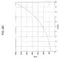
- FIGS. 3A-3Eare graphical representations of the hydraulic pressure, motor torque, hydraulic flow rate, shaft RPM, and generator output power for a single pressure profile for a representative pressure range produced by the system of FIG. 2 ;
- FIGS. 4A-4Eare graphical representations of the hydraulic pressure, shaft torque, hydraulic flow rate, hydraulic motor RPM, and motor output power for a series of pressure profiles for an exemplary cyclic operation of the system of FIG. 2 ;
- FIG. 5is a schematic diagram of the major components related to a system and method for providing a constant output from a compressed gas energy storage and recovery system using a fixed displacement hydraulic motor-pump and a continuously variable transmission;
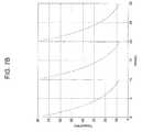
- FIGS. 6A-6Hare graphical representations of the hydraulic pressure, hydraulic motor torque, hydraulic flow rate, hydraulic motor shaft RPM, generator output power, CVT gear ratio, generator shaft RPM, and generator torque for a single pressure profile for a representative pressure range produced by the system of FIG. 5 ;
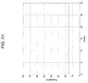
- FIGS. 7A-7Hare graphical representations of the hydraulic pressure, hydraulic motor torque, hydraulic flow rate, hydraulic motor shaft RPM, generator output power, CVT gear ratio, generator shaft RPM, and generator torque for a series of pressure profiles for an exemplary cyclic operation of the system of FIG. 5 ;
- FIG. 8is a schematic diagram of the major components related to conversion efficiency for a compressed air energy storage and recovery system using staged hydraulic conversion
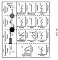
- FIG. 9is a schematic diagram of the major components related to conversion efficiency for a compressed air energy storage and recovery system using staged hydraulic conversion, where a fixed displacement hydraulic motor-pump is used, including graphic representations of the various operational parameters, such as piston profile, power, pressure, flow, torque, RPM, current and voltage versus time for various stages or operation;
- FIG. 10is a schematic diagram of the major components related to conversion efficiency for a compressed air energy storage and recovery system using staged hydraulic conversion, where a variable displacement hydraulic motor-pump and non-optimized control scheme is used, including graphic representations of the various operational parameters, such as piston position, power, pressure, flow, torque, RPM, current and voltage versus time for the various stages;
- FIG. 11is a schematic of the components related to conversion efficiency for compressed air energy storage using staged hydraulic conversion, where a variable displacement hydraulic motor-pump and optimal control scheme is used for providing constant power, and graphic representations of the various operational parameters, such as piston position, power, pressure, flow, torque, RPM, current and voltage versus time for the various stages;
- FIG. 12is a schematic representation of the major components related to one embodiment of a system and method for providing constant power, RPM, and torque from a hydraulic input having a widely-varying pressure profile and using a variable displacement hydraulic motor;
- FIG. 13is a schematic representation of the major components related to another embodiment of a system and method for providing constant power, RPM, and torque from a hydraulic input having a widely-varying pressure profile and using a variable displacement hydraulic motor;
- FIGS. 14A-14Care graphical representations of the hydraulic pressure, flow rate, and motor output power for a single pressure profile for a representative pressure range related to the systems and methods of FIGS. 12 and 13 ;
- FIGS. 15A-15Eare graphical representations of the hydraulic pressure, motor displacement, motor RPM, motor torque, and motor output power for a series of pressure profiles for an example cyclic operation of the systems and methods of FIGS. 12 and 13 ;
- FIG. 16is a schematic representation of the major components related to another embodiment of a system and method for providing constant power, RPM, and torque from a hydraulic input having a widely-varying pressure profile and using a variable displacement hydraulic motor;
- FIG. 17Ais a schematic representation of a hydraulic drivetrain including a single fluid power source and a single fluid power consumer, wherein the fluid power consumer is a fixed displacement hydraulic motor;
- FIG. 17Bis an equation describing the torque, pressure, and displacement relationship for the hydraulic motor in FIG. 17A ;
- FIG. 18Ais a schematic representation of a hydraulic drivetrain including a single fluid power source and multiple fluid power consumers, wherein the fluid power consumers are fixed displacement hydraulic motors;
- FIG. 18Bis a set of equations describing the torque, pressure, and displacement relationships for the hydraulic motors in FIG. 18A ;
- FIG. 19Ais a schematic representation of a hydraulic drivetrain including a single fluid power source and multiple fluid power consumers wherein the fluid power consumers are variable displacement hydraulic motors;
- FIG. 19Bis a set of equations describing the torque, pressure, and displacement relationships for the hydraulic motors in FIG. 19B ;
- FIG. 20Ais a schematic representation of a hydraulic drivetrain including a single fluid power source and a single fluid power consumer, wherein the fluid power source is a non-controlled, non-constant pressure source and the fluid power consumer is a variable displacement motor producing a constant output speed;
- FIG. 20Bis an equation describing the torque, pressure, and displacement relationship for the hydraulic motor in FIG. 20A ;
- FIG. 21is a schematic representation of the major components for an alternative system and method for improving drivetrain efficiency for a compressed gas energy storage and recovery system using staged hydraulic conversion;
- FIG. 22is a schematic representation of one embodiment of a high-efficiency, variable volume hydraulic motor-pump for use in the system and method of FIG. 21 ;
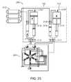
- FIG. 23is a schematic representation of the major components for an alternative system and method for improving drivetrain efficiency for a compressed gas energy storage and recovery system using staged hydraulic conversion.
- FIG. 24is a schematic representation of one embodiment of a high-efficiency, variable volume hydraulic motor-pump for use in the system and method of FIG. 23 .
- FIG. 1depicts generally a basic hydraulic-pneumatic energy conversion system 1 that stores and recovers electrical energy using at least one hydraulic motor.
- the system 1includes one or more high-pressure gas/air storage tanks 2 a , 2 b , . . . 2 n .
- Each tank 2is joined in parallel via a manual valve(s) 4 a , 4 b , . . . 4 n , respectively, to a main air line 8 .
- the valves 4are not limited to manual operation, as the valves can be electrically, hydraulically, or pneumatically actuated, as can all of the valves described herein.
- the tanks 2are each provided with a pressure sensor 12 a , 12 b . . . 12 n and a temperature sensor 14 a , 14 b . . . 14 n .
- These sensors 12 , 14can output electrical signals that can be monitored by a control system 20 via appropriate wired and wireless connections/communications. Additionally, the sensors 12 , 14 could include visual indicators.
- the control system 20can be any acceptable control device with a human-machine interface.
- the control system 20could include a computer (for example a PC-type) that executes a stored control application in the form of a computer-readable software medium.
- the control applicationreceives telemetry from the various sensors to be described below, and provides appropriate feedback to control valve actuators, motors, and other needed electromechanical/electronic devices.
- the system 1further includes pneumatic valves 6 a , 6 b , 6 c , . . . 6 n that control the communication of the main air line 8 with an accumulator 16 and an intensifier 18 .
- the system 1can include any number and combination of accumulators 16 and intensifiers 18 to suit a particular application.
- the pneumatic valves 6are also connected to a vent 10 for exhausting air/gas from the accumulator 16 , the intensifier 18 , and/or the main air line 8 .
- the system 1further includes hydraulic valves 28 a , 28 b , 28 c , 28 d . . . 28 n that control the communication of the fluid connections of the accumulator 16 and the intensifier 18 with a hydraulic motor-pump 30 .
- the specific number, type, and arrangement of the hydraulic valves 28 and the pneumatic valves 6are collectively referred to as the control valve arrangements.
- the valvesare generally depicted as simple two way valves (i.e., shut-off valves); however, the valves could essentially be any configuration as needed to control the flow of air and/or fluid in a particular manner.
- the hydraulic line between the accumulator 16 and valves 28 a , 28 b and the hydraulic line between the intensifier 18 and valves 28 c , 28 dcan include flow sensors 26 that relay information to the control system 20 .
- the motor-pump 30can be a fixed or variable displacement piston-type assembly having a shaft 31 (or other mechanical coupling) that drives, and is driven by, a combination electrical motor and generator assembly 32 .
- the motor-pump 30could also be, for example, an impeller, vane, or gear type assembly.
- the motor-generator assembly 32is interconnected with a power distribution system and can be monitored for status and output/input level by the control system 20 .
- the system 1can also include heat transfer subsystems in fluid communication with the air chambers of the accumulators and intensifiers and the high pressure storage tanks that provide improved isothermal expansion and compression of the gas.
- heat transfer subsystemsare described in detail in the above incorporated patent applications.
- FIG. 2depicts the major components related to a system and method for providing constant power from a hydraulic-pneumatic energy storage and recovery system using staged hydraulic conversion that provides a widely-varying pressure profile to a FD hydraulic motor-pump by using a closed loop control system and a variable frequency drive (VFD) to adjust the load seen by the electric generator and to produce constant electric power at a constant frequency.
- VFDvariable frequency drive
- the major regions illustrated in FIG. 2include a source of pressurized hydraulic fluid 101 , such as a hydraulic-pneumatic accumulator or system as described above with respect to FIG. 1 , which is driving the FD hydraulic motor-pump 110 providing rotary motion (as indicated by arrow 121 ) of an output shaft 120 .
- a source of pressurized hydraulic fluid 101such as a hydraulic-pneumatic accumulator or system as described above with respect to FIG. 1 , which is driving the FD hydraulic motor-pump 110 providing rotary motion (as indicated by arrow 121 ) of an output shaft 120 .
- the output shaftdrives an electric motor-generator 130 having electric output 131 .
- This electric output 131is the input of the VFD 140 having an electric output 141 .
- the outlet of the hydraulic motor 110is at low pressure and is directed to a hydraulic fluid reservoir 102 ; however, the outlet could be directed back to the source of pressurized hydraulic fluid 101 , as shown in FIG. 1 .
- a torque sensor 150 on the shaft 120provides information via a channel 151 to the VFD 140 , which adjusts the load seen by the generator accordingly.
- the output 141 of the VFD 140is a sinusoidal voltage having a constant frequency (e.g., 60 Hz) and constant power.
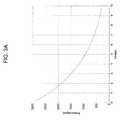
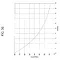
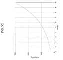
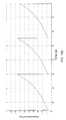
- FIGS. 3A-3Eare graphical representations of the hydraulic pressure (A), motor torque (B), hydraulic flow rate (C), shaft RPM (D), and generator output power (E) for a single pressure profile for a representative pressure range delivered to the FD hydraulic motor-pump using the system and method of the invention for providing constant power from the widely-varying pressure profile.
- Ahydraulic pressure
- Bhydraulic flow rate
- Chydraulic flow rate
- Dshaft RPM
- Egenerator output power
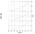
- FIGS. 4A-4Eare graphical representations of the hydraulic pressure (A), shaft torque (B), hydraulic flow rate (C), hydraulic motor RPM (D), and motor output power (E) for a series of pressure profiles during a cyclic operation of the system of FIG. 2 .
- FIG. 4Aa set of three cyclical pressure profiles are shown for a simulated process where successive hydraulic pneumatic accumulators are discharged with an initial pressure of 3000 psi. As the compressed gas expands in each successive accumulator forcing out hydraulic fluid, the pressure falls from 3000 psi to approximately 300 psi.
- torquedecreases with decreasing pressure.
- the load on the generator(and, consequently, the mechanical load on the FD hydraulic motor shaft) is decreased by the VFD in proportion to the sensed torque in such a way that flow rate through the FD motor increases as shown in FIG. 4C .
- Shaft RPMidentical for both the hydraulic and electric machines, increases proportionately as shown in FIG. 4D . In this way, power is kept nearly constant as a function of time as shown in FIG. 4E .
- FIG. 5depicts the major components related to an alternative system and method for providing a constant output (e.g., power, current, voltage, frequency) from a hydraulic-pneumatic energy storage and recovery system using staged hydraulic conversion that provides a widely-varying pressure profile to a FD hydraulic motor-pump by using a closed loop control system and a continuously variable transmission (CVT).
- the systems and methods of the inventionare capable of maintaining constant RPM for the electric generator and so produce constant electric power at a constant frequency.
- the major regions illustrated in FIG. 5include the source of pressurized hydraulic fluid 101 , as discussed above, which is driving the FD hydraulic motor 110 , providing rotary motion (as indicated by arrow 121 ) of the output shaft 120 .
- the output shaft 120drives the CVT 160 whose output shaft 165 drives the electric motor-generator 130 having electric output 131 .
- a torque sensor 150 on the shaft 120 of the FD hydraulic motor 110communicates information by a channel 151 to a control unit (e.g., a computer) 170 .
- This control unitcontrols the effective gear ratio of the CVT through a mechanical linkage (or combination of information channel and mechanical linkage) 175 .
- the effective gear ratio of the CVTis adjusted in such a way as to provide constant RPM and torque to the shaft 165 of the electric generator 130 .
- the outlet of the hydraulic motor 110is at low pressure and is directed to a hydraulic fluid reservoir 102 , but as discussed above could be directed back to the source of pressurized hydraulic fluid 101 .
- the output 131 of the electric generator 130is a sinusoidal voltage having a constant frequency (e.g., 60 Hz) and constant power.
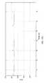
- FIGS. 6A-6Hare graphical representations of the hydraulic pressure (A), hydraulic motor torque (B), hydraulic flow rate (C), hydraulic motor shaft RPM (D), generator output power (E), CVT gear ratio (F), generator RPM (G), and generator torque (H) for a single pressure profile for a representative pressure range delivered to the fixed hydraulic motor-pump using the system and method of the invention for providing constant power from the widely-varying pressure profile.
- a pressure profileis depicted for a simulated system using a hydraulic pneumatic accumulator with an initial pressure of 3000 psi. As the compressed gas expands in the accumulator forcing out hydraulic fluid, the pressure falls from 3000 psi to approximately 300 psi.
- Torque on the output shaft of the hydraulic motordecreases in proportion to the pressure ( FIG. 6B ).
- the effective gear ratio of the CVTis adjusted in proportion to torque in such a way that load on the FD hydraulic motor shaft is decreased and the flow rate through the FD motor increases as shown in FIG. 6C .
- Shaft RPM of the FD hydraulic motorincreases proportionately, as shown in FIG. 6D .
- the power output of the hydraulic motoris kept nearly constant as a function of time, as shown in FIG. 6E .
- Shaft RPM ( FIG. 6G ) and torque ( FIG. 6H ) on the other side of the CVT, i.e., at the input of the electric generator,remains constant by continuously varying the gear ratio as shown in FIG. 6F . In this way, the output frequency, voltage, current, and power of the electric generator remains nearly constant.
- FIGS. 7A-7Hare graphical representations of the hydraulic pressure (A), hydraulic flow rate (B), motor RPM (C), hydraulic motor shaft RPM (D), generator output power (E), CVT gear ratio (F), generator RPM (G), and generator torque (H) for a series of pressure profiles generated during a cyclic operation of the system of FIG. 5 .
- FIG. 7Aa set of three cyclical pressure profiles are shown for the simulated process where successive hydraulic pneumatic accumulators are discharged with an initial pressure of 3000 psi. As the compressed gas expands in each successive accumulator forcing out hydraulic fluid, the pressure falls from 3000 psi to approximately 300 psi. Torque on the output shaft of the hydraulic motor decreases in proportion to the pressure ( FIG.
- FIG. 8depicts generally the major components for improving conversion efficiency of compressed air energy storage using staged hydraulic conversion and the four major energy conversion stages.
- the major regions illustrated in FIG. 8include compressed gas energy 201 , which is converted to hydraulic energy 202 via a pneumatic to hydraulic device, such as an accumulator 210 or intensifier 220 , with the pneumatic to hydraulic pressure ratio determined by relative piston sizing and selected based on pressure levels and actuation of valves 270 as, for example, described in the above-incorporated patent applications.
- the dashed line separating compressed gas energy 201 and hydraulic energy 202represents a transition between energy types and thus has an associated efficiency—compressed gas potential energy to work done by the hydraulic fluid. Optimization of this efficiency, in part through the use of near isothermal expansion and compression, is also discussed in the above incorporated patent applications.
- the pressurized hydraulic fluid in region 202is driven by or used to drive a hydraulic motor-pump 230 , converting the work performed by or on the fluid to or from mechanical energy 203 typically in the form of a rotating drive shaft.
- This transitionindicated by the dashed line separating hydraulic energy 202 and mechanical energy 203 , represents the hydraulic to mechanical conversion efficiency and is dependent in part on the efficiency characteristics of the hydraulic motor-pump 230 , which vary with pressure/torque and flow/RPM.
- this drive shaftwill be connected to an electric motor-generator 240 , which converts the mechanical energy 203 to electrical energy 204 .
- This transition, indicated by the dashed line separating mechanical energy 203 and electrical energy 204represents the mechanical to electrical conversion efficiency and is dependent in part on the efficiency characteristics of the electric motor-generator 240 , which vary with torque and RPM.
- this electrical motor-generator 240will be further connected to power electronics 250 to condition the electrical motor-generator 240 input/output power to the power supply 260 (e.g., an electrical power grid).
- the effect of the addition of power electronics 250 hereis included in overall mechanical to final electrical efficiency. As proposed in FIGS. 10 and 11 , direct operation of the electric motor-generator 250 from the power supply 260 can improve overall efficiency by removing any inefficiency from the addition of power electronics 250 .
- FIG. 9depicts generally the major components related to conversion efficiency for compressed air energy storage using staged hydraulic conversion, where a FD hydraulic motor-pump 230 is used.
- FIG. 9illustrates the four major energy conversion stages discussed above (compressed gas energy 201 , hydraulic energy 202 , mechanical energy 203 , and electrical energy 204 ).
- FIG. 9graphically depicts the various operational parameters of the system, such as piston position, power, pressure, flow, torque, RPM, current and voltage versus time for those stages. It should be noted that for simplicity of description, the case of expansion (compressed air energy storage and recovery system discharge) is displayed and described for the graphs in FIG. 9 , but the case of compression (system charging) can be imagined by reversing the time axis on the various plots.
- a set amount of compressed gasis admitted and then expanded in a pneumatic hydraulic device such as the accumulator 210 driving hydraulic fluid through hydraulic motor-pump 230 .
- the hydraulic fluid pressure(directly related to compressed gas pressure) falls as a function of time as indicated in the first half of graph 320 .
- two expansionsare shown for the time scale.
- a second pneumatic hydraulic devicesuch as the intensifier 220 admits and expands a fixed amount of compressed gas.
- the flow ratewill tend to drop with pressure as indicated in graph 321 , with a fixed load.
- Piston speed in the accumulator 210changes with flow rate, and thus piston position is related in an integral fashion to flow rate as indicated in graph 310 .
- powerdrops as a function of time as the product of graph 320 and graph 321 as indicated in graph 322 .
- output torqueis related to pressure
- graph 320as indicated in graph 330
- hydraulic motor output RPMis related to flow graph 321 as indicated in graph 331 .
- motor-generator 240 currentis related to torque graph 330 as indicated in graph 340 , and thus also tracks with pressure.
- Electric motor-generator 240 voltageis related to RPM graph 331 as indicated in graph 341 . Power in each stage: compressed gas energy 201 , hydraulic energy 202 , mechanical energy 203 , and electrical energy 204 , are closely related, scaled by efficiencies of conversions, and fall with time.
- Power electronics 250can be used to transform voltage to a constant value as a function of time for a final power supply 260 (e.g. for use on the power grid), as indicated in graph 351 .
- short-term energy storage devicessuch as ultracapacitors can be used with the power electronics to smooth current, graph 350 , and power supply, graph 352 , as a function of time. This addition of power electronics and potentially short-term energy storage adds cost and complexity to the energy storage and recovery system, while adding additional electric conversion losses, potentially decreasing overall system efficiency.
- efficiency of both the FD hydraulic motor-pump 230 and electric motor-generator 240are dependent on operating torque and RPM, and thus when varied over a large range as indicated in graph 330 and graph 331 both may suffer lower efficiencies over the course of a full expansion than if operated over a narrow or fixed range of torque and RPM.
- near constant torque and RPMcan be achieved by using a VFD or CVT.
- FIG. 10depicts generally the major components related to conversion efficiency for compressed air energy storage using staged hydraulic conversion, where a VD hydraulic motor-pump 230 is used.
- the use of the VD hydraulic motor-pumpimproves the conversion efficiency of the hydraulic-pneumatic energy storage and recovery system and allows a user to achieve near constant expansion or compression power in the system, while maintaining near constant RPM or torque at the shaft of an electric motor-generator.
- FIG. 10illustrates the four major energy conversion stages discussed above (compressed gas energy 201 , hydraulic energy 202 , mechanical energy 203 , and electrical energy 204 ).
- FIG. 10graphically depicts the various operational parameters of the system, such as piston position, power, pressure, flow, torque, RPM, current and voltage versus time for those regions.
- a set amount of compressed gasis admitted and then expanded in a pneumatic hydraulic device such as the accumulator 210 driving hydraulic fluid through the hydraulic motor-pump 230 .
- the hydraulic fluid pressure(directly related to compressed gas pressure) falls as a function of time as indicated in the first half of graph 420 .
- two expansionsare shown for the time scale.
- a second pneumatic hydraulic devicesuch as intensifier 220 admits and expands a fixed amount of compressed gas.
- the flow rateis controlled by both by the RPM and the displacement per revolution of the motor.
- the displacement per revolution of the motorcan be controlled in a VD motor-pump.
- the flow ratecan be set in such a way as to increase with decreasing pressure as shown in graph 421 , by increasing the displacement per revolution.
- a control systemis implemented to maintain a nearly constant RPM as indicated in graph 431 .
- Piston speed in accumulator 210changes with flow rate, and thus piston position is related in an integral fashion to flow rate as indicated in graph 410 .
- hydraulic poweris pressure times flow rate, power varies as a function of time as the product of graph 420 and graph 421 as indicated in graph 422 .
- hydraulic motor-pump output torqueis related to pressure, graph 420 , times the displacement as a function of time (a fixed RPM displacement has the same curve as flow as shown in graph 421 ) as indicated in graph 430 .
- Hydraulic motor-pump 230 output RPMis related to flow graph 421 as indicated in graph 431 .
- electric motor-generator 240 currentis related to torque graph 430 as indicated in graph 440 .
- Electric motor-generator 240 voltageis related to RPM graph 431 as indicated in graph 441 .
- Power in each compressed gas energy 201 , hydraulic energy 202 , mechanical energy 203 , and electrical energy 204 stagesis closely related, scaled by efficiencies of conversions, and fall with time.
- output voltage from the electric motor-generator 240can be matched to the required output, such as the electrical grid power.
- power electronics 250can be removed from the system, saving substantial system costs.
- Short-term energy storage devicessuch as ultracapacitors, could be used to smooth current 440 and power output 442 as a function of time.
- the efficiency of the electric motor-generator 240is dependent on operating torque and RPM, by limiting the variation in torque and RPM to operation operated over a narrow or fixed range, mechanical to electrical conversion can be increased.
- FIG. 11depicts generally the major components related to conversion efficiency for compressed air energy storage using staged hydraulic conversion, where a VD hydraulic motor-pump 230 is used.
- FIG. 11illustrates the four major energy conversion stages discussed above and graphically depicts the various operational parameters, such as piston position, power, pressure, flow, torque, RPM, current and voltage versus time for those regions.
- FIG. 11is closely related to FIG. 10 , but shows the full potential of an optimized control scheme for the VD hydraulic motor-pump 230 . It should be noted that for simplicity of description, the case of expansion (compressed air energy storage and recovery system discharge) is displayed and described for the graphs in FIG. 11 , but the case of compression (system charging) can be imagined by reversing the time axis on the various plots.
- a set amount of compressed gasis admitted and then expanded in a pneumatic hydraulic device, such as an accumulator 210 driving hydraulic fluid through the hydraulic motor-pump 230 .
- the hydraulic fluid pressure(directly related to compressed gas pressure) falls as a function of time as indicated in the first half of graph 520 .
- two expansionsare shown for the time scale.
- a second pneumatic hydraulic devicesuch as an intensifier 220 admits and expands a fixed amount of compressed gas.
- the flow rateis controlled by both the RPM and the displacement per revolution of the motor.
- the displacement per revolution of the motorcan be controlled in a VD motor-pump.
- the flow ratecan be set in such a way as to increase with decreasing pressure as shown in graph 521 by increasing the displacement per revolution.
- a control systemis implemented to maintain a nearly constant torque or RPM as indicated in graph 530 and graph 531 .
- Piston speed in the accumulator 210changes with flow rate, and thus piston position is related in an integral fashion to flow rate as indicated in graph 510 .
- powercan be made constant as indicated in graph 522 if pressure varies inversely with flow rate as a function of time as indicated in graph 520 and graph 521 .
- hydraulic motor output torqueis related to pressure, graph 520 , times the displacement as a function of time (a fixed RPM displacement has the same curve as flow as shown in graph 521 ) as indicated in graph 530 .
- Hydraulic motor output RPMis related to flow 521 as indicated in 531 .
- electric motor-generator 240 currentis related to torque graph 530 as indicated in graph 540 .
- Electric motor-generator 240 voltageis related to RPM graph 531 as indicated in graph 541 .
- Power in each stage: compressed gas energy 201 , hydraulic energy 202 , mechanical energy 203 , and electrical energy 204are closely related, scaled by efficiencies of conversions, and fall with time.
- output voltage from 240can be matched to the required output, such as the electrical grid power.
- power electronicscan be removed from the system, saving substantial system costs.
- FIG. 12depicts an alternative arrangement of the major components related to the systems and methods for providing constant power, RPM, and torque from a hydraulic input having a widely-varying pressure profile, in this case using a VD motor-pump and open loop control system. Similar to those described above (see, e.g., FIGS. 2-7 ), the major regions illustrated in FIG. 12 include a source of pressurized hydraulic fluid 101 , such as a hydraulic-pneumatic accumulator or system as described above, which is driving a VD hydraulic motor 110 providing rotary motion (as indicated by arrow 121 ) of an output shaft 120 .
- a source of pressurized hydraulic fluid 101such as a hydraulic-pneumatic accumulator or system as described above, which is driving a VD hydraulic motor 110 providing rotary motion (as indicated by arrow 121 ) of an output shaft 120 .
- the outlet of the motor 110is at low pressure and is directed to a hydraulic fluid reservoir 102 ; however, the outlet could be directed back to the system providing the source of pressurized hydraulic fluid 101 .
- the displacement of motor 110is controlled via displacement controller 132 .
- FIG. 13depicts an alternative arrangement of the major components related to the systems and methods for providing constant power, RPM, and torque from a hydraulic input having a widely-varying pressure profile, in this case using a VD motor-pump and a closed loop control system.
- the major regions illustrated in FIG. 13include a source of pressurized hydraulic fluid 101 , which is driving a VD hydraulic motor 110 providing rotary motion (arrow 121 ) of an output shaft 120 .
- the outlet of the motor 110is at low pressure and is directed to a hydraulic fluid reservoir 102 , but could be returned to the system providing the source of pressurized hydraulic fluid 101 .
- the displacement of the motor 110is controlled via displacement controller 132 , which is based on RPM and/or torque measurements from a RPM/torque sensor 134 .
- FIGS. 14A-14Care graphical representations of the hydraulic pressure, flow rate, and motor output power for a single pressure profile for a representative pressure range related to the system and method for providing constant power, RPM, and torque from a widely-varying pressure hydraulic input of FIG. 13 .
- a pressure profileis depicted for a simulated system using a hydraulic pneumatic accumulator with an initial pressure of 3000 psi. As the compressed gas expands in the accumulator forcing out hydraulic fluid, the pressure falls from 3000 psi to approximately 300 psi. The VD hydraulic motor displacement is changed such that RPM and torque are nearly constant, increasing hydraulic flow rate through the motor, as shown in FIG. 14B , as pressure decreases. In this way, power is kept nearly constant as a function of time as shown in FIG. 14C .
- FIGS. 15A-15Eare graphical representations of the hydraulic pressure, motor displacement, motor RPM, motor torque, and motor output power for a series of pressure profiles for an example cyclic operation of the system and method for providing constant power, RPM, and torque from a widely-varying pressure hydraulic input of FIG. 13 .
- FIG. 15Aa set of three cyclical pressure profiles are shown for the simulated process where successive hydraulic pneumatic accumulators are discharged with an initial pressure of 3000 psi. As the compressed gas expands in each successive accumulator forcing out hydraulic fluid, the pressure falls from 3000 psi to approximately 300 psi.
- the displacement setting of the VD hydraulic motoris controlled in this example by a PID controller set to achieve constant RPM. As shown in FIGS.
- FIG. 16depicts an alternative arrangement of the major components related to the systems and methods for providing constant power, RPM, and torque from a hydraulic input having a widely-varying pressure profile, in this case using a VD motor-pump and a control system using predictive information and feedback.
- the major regions illustrated in FIG. 16include a source of pressurized hydraulic fluid 101 , which is driving a VD hydraulic motor 110 providing rotary motion (arrow 121 ) of an output shaft 120 .
- the outlet of the motor 110is at low pressure and is directed to a hydraulic fluid reservoir 102 , but could be returned to the system providing the source of pressurized hydraulic fluid 101 .
- the displacement of the motor 110is controlled via displacement controller 132 , which is based on computed inputs from the system controller 136 .
- the system controller 136incorporates predictive information based on current system parameters (such as RPM/torque measurements from a RPM/torque sensor 134 , as well as piston positions, pressures, and/or temperatures) and procedures such as switching pressures to set displacement such that variations in output around state changes can be minimized.
- FIG. 17Ais a schematic diagram of a hydraulic drivetrain including a single fluid power source and a single fluid power consumer, in which the fluid power consumer is a FD hydraulic motor.
- a driving machine 604is used to turn a shaft 605 powering a VD pump 606 that pumps fluid from a tank 602 into a high-pressure line 601 . Fluid from the high pressure line 601 flows through a FD hydraulic motor 610 and back into the tank 602 .
- the motor 610converts the fluid power into mechanical power, driving shaft 663 and powering the driven machine 660 .
- the equation depicted in FIG. 17Bshows the torque, pressure, and displacement relationship of FD hydraulic motor 610 .
- the displacement 690 of motor 610is constant and fixed. Therefore, the pressure 680 in the high pressure line 601 and experienced by motor 610 must be increased or decreased to increase or decrease the output torque 670 of the motor 610 . In drivetrain 600 , this is accomplished by adjusting the displacement 607 of pump 606 , which increases the fluid power provided to line 601 .
- FIG. 18Ais a schematic diagram of a hydraulic drivetrain including a single fluid power source and multiple fluid power consumers, in which the fluid power consumers are FD hydraulic motors.
- a driving machine 704is used to turn a shaft 705 powering a VD pump 706 that pumps fluid from a tank 702 into a high-pressure line 701 . Fluid from the high pressure line 701 flows through FD hydraulic motors 711 , 712 and back into the tank 702 .
- the motors 711 , 712convert the fluid power into mechanical power, driving shafts 763 , 764 to power the driven machines 761 , 762 .
- the equation depicted in FIG. 18Bshows the torque, pressure, and displacement relationship of the FD hydraulic motors 711 , 712 .
- the displacements 791 , 792 of the motors 711 , 712are constant and fixed. Therefore, the pressures 781 , 782 in the high pressure lines 733 , 734 that are experienced by the motors 711 , 712 must be increased or decreased in order to increase or decrease the output torques 771 , 772 of the motors 711 , 712 .
- Both fluid power consumers, motors 711 , 712are affected by the pressure in the high-pressure line 701 , which therefore cannot be used to individually control the outputs of the motors 711 , 712 the way the pressure in line 601 in FIG.
- 17Acan control the output of motor 610 . Therefore, the pressure in the high-pressure line 701 is held constant or nearly constant by adjusting the displacement 707 of pump 706 , which increases the fluid power provided to line 701 .
- a hydraulic accumulator 703is used to reduce pressure fluctuations. Since there are multiple fluid power consumers in drivetrain system 700 , pressure-reducing valves 731 , 732 are used to control the pressures 781 , 782 in the fluid lines 733 , 734 at the inlets of the motors 711 , 712 , thus individually controlling output torques 771 , 772 of the motors. The disadvantage with this approach is that a significant amount of energy is lost and converted to heat by throttling the flow through valves 731 , 732 to control the pressure, thereby greatly reducing system efficiency.
- FIG. 19Ais a schematic of a hydraulic drivetrain including a single fluid power source and multiple fluid power consumers, in which the fluid power consumers are VD hydraulic motors.
- VD hydraulic motorswere developed to provide torque control from a constant or nearly constant pressure fluid power source without the need for throttling valves. By eliminating the energy losses associated with throttling control valves, system efficiencies are greatly increased.
- a driving machine 804is used to turn a shaft 805 powering a VD pump 806 that pumps fluid from the tank 802 into the high-pressure line 801 .
- Fluid from the high pressure line 801flows through VD hydraulic motors 811 , 812 and back to the tank 802 .
- the motors 811 , 812convert the fluid power into mechanical power, driving shafts 863 , 864 to power the driven machines 861 , 862 .
- both fluid power consumers in FIG. 19A , motors 811 , 812are affected by the pressure in the high-pressure line 801 , which therefore cannot be used to individually control the outputs of the motors 811 , 812 the way the pressure in line 601 in FIG.
- 17Acan control the output of motor 610 . Therefore, the pressure in the high-pressure line 801 is held constant or nearly constant by adjusting the displacement 807 of pump 806 , which increases the fluid power provided to line 801 .
- a hydraulic accumulator 803is used to reduce pressure fluctuations.
- the equation depicted in FIG. 19Bshows the torque, pressure, and displacement relationship of the VD hydraulic motors 811 , 812 .
- the displacements 891 , 892 of the motors 811 , 812are variable and can be controlled by displacement controls 831 , 832 .
- the displacements 881 , 882 of the motors 811 , 812can be increased or decreased via displacement controls 831 , 832 , thus increasing or decreasing the output torques 871 , 872 of the motors 811 , 812 to accommodate varying loads on the shafts 863 , 864 required by the driven machines 861 , 862 .
- FIG. 20Adepicts an embodiment of a hydraulic drivetrain in which the driven machine requires constant torque and the displacement of the VD hydraulic motor is controlled to account for changes in the motor inlet pressure, which is non-constant and non-controllable.
- the hydraulic motor 910is powered by a non-controlled, non-constant pressure source 901 , such as, for example, the compressed gas energy storage and recovery system using staged hydraulic conversion described above. Fluid flows from the non-constant pressure source 901 through the VD hydraulic motor 910 and into tank 902 .
- the motor 910converts the fluid power into mechanical power, driving a shaft 963 and powering a driven machine 960 that requires constant or near constant input torque.
- the pressure differential 980 experienced by the motor 910is provided by the non-constant pressure source 901 , and is thus non-constant and non-controlled.
- displacement 930is actively controlled to be inversely proportional to the pressure differential 980 in order to compensate for the varying nature of the pressure input and provide the constant or near constant motor torque output 970 required by the driven machine 960 . See the equation depicted in FIG. 20B , which shows the torque, pressure, and displacement relationship for the hydraulic motor in FIG. 20A .
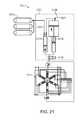
- FIG. 21is a schematic representation of an alternative embodiment of a system and method for improving drivetrain efficiency for a compressed gas energy storage using hydraulic conversion to provide a constant output.
- the system 2100is integrated with a hydraulic motor-pump 2110 having one each of a high pressure and low pressure input/output, with a series of pistons each driven using a computer controlled valve actuation scheme to allow for variable displacement operation at high efficiency, and described with respect to FIG. 22 .
- FIG. 22depicts the hydraulic motor-pump 2110 , having one each of a high pressure and low pressure input/output 2130 and 2140 , with a series of pistons each driven using a computer controlled valve actuation scheme to allow for variable displacement operation at high efficiency.
- the major componentsinclude six radial piston assemblies 2110 a - f , each composed of a piston 2111 attached to an off-center rotating cam 2120 that turns a center axle 2121 .
- Each piston 2111reciprocates in a housing 2112 that is allowed to pivot about a fixed end 2113 .
- High pressure hydraulic fluidwhich is brought to/from the motor-pump 2110 through a high pressure hydraulic port 2130 , is distributed to/from each piston assembly 2110 a - f through high pressure lines 2132 .
- low pressure hydraulic fluidis brought to/from the motor-pump 2110 through a low pressure hydraulic port 2140 and is distributed to/from each piston assembly 2110 a - f through low pressure lines 2142 .
- high pressure valves 2131may or may not be actuated (to an open position) each time the cam 2120 forces the piston 2111 near the top of the housing 2112 .
- the high pressure valve 2131is not actuated (to an open position)
- the low pressure valveremains open allowing low pressure fluid to freely enter and exit the housing resulting in minimal fluid drag.
- the pistonalways completes a full stroke, thereby increasing motor-pump efficiency.
- the motor-pump 2110 depicted in FIG. 22has a radial piston layout with six pistons; however, various implementations of the systems and methods described herein may use a motor-pump that includes more or less pistons and/or an axial piston design.
- One implementation of this motor-pumpis the “Digital Displacement” motor-pump designed by Artemis IP in Edinburgh, Scotland.
- the compressed gas energy storage and recovery system illustrated hereinconsists of compressed gas storage vessels (or caverns) 2102 connected to a hydraulic conversion system 2101 , such as those described above.
- the hydraulic conversion systemmay consist of one or more hydraulic pneumatic accumulators 2116 and one or more hydraulic pneumatic intensifiers 2118 .
- the air side of the hydraulic pneumatic accumulator 2116is connected to the compressed gas storage vessels 2102 and the hydraulic pneumatic intensifier 2118 via air lines with shut-off valves 2106 .
- the air side of the hydraulic pneumatic intensifier 2116is also in communication with the ambient environment through a vent port and shut-off valve 2106 .
- the hydraulic outputs of accumulator 2116 and intensifier 2118are routed through a four way two position valve 2128 to hydraulic motor-pump 2110 .
- a VD motor-pumpin combination with the system for compressed gas energy storage and recovery allows for operation over a broad pressure range while maintaining nearly constant RPM, torque, and power.
- the digitally controlled motor-pump 2110 described hereinallows for a substantially higher efficiency over a broader pressure range than conventional VD motor-pumps.
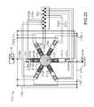
- FIG. 23is a schematic representation of an alternative embodiment of a system and method for improving drivetrain efficiency for a compressed gas energy storage using hydraulic conversion to provide a constant power output.
- the system 2200is integrated with a hydraulic motor-pump 2210 having two or more high pressure input/outputs, with a series of pistons each driven using a computer controlled valve actuation scheme to allow for variable displacement operation at high efficiency.
- the hydraulic motor-pumpis described with respect to FIG. 24 .
- FIG. 24is a schematic of the hydraulic motor-pump 2210 , having two or more high pressure input/outputs 2240 and 2230 , with a series of pistons each driven using a computer controlled valve actuation scheme to allow for variable displacement operation at high efficiency.
- the major componentsinclude six radial piston assemblies 2110 a - f , each composed of a piston 2111 attached to an off-center rotating cam 2120 which turns a center axle 2121 .
- Each piston 2111reciprocates in a housing 2112 that is allowed to pivot about a fixed end 2113 .
- High pressure hydraulic fluidwhich is brought to/from the motor-pump 2210 through two (or more) high pressure hydraulic ports 2230 bdf and 2230 ace is distributed to/from each piston assembly 2110 b,d,f and 2110 a,c,e through high pressure lines 2232 bdf and 2232 ace , respectively.
- low pressure hydraulic fluidis brought to/from the motor-pump 2210 through one or more low pressure hydraulic ports 2240 and is distributed to/from each piston assembly 2110 a - f through low pressure lines 2242 .
- high pressure valves 2131may or may not be actuated (to an open position) each time the cam 2120 forces the piston 2111 near the top of the housing 2112 .
- the high pressure valve 2131is not actuated (to an open position)
- the low pressure valveremains open allowing low pressure fluid to freely enter and exit the housing resulting in minimal fluid drag.
- the pistonalways completes a full stroke, thereby increasing motor-pump efficiency.
- the motor-pumpcan achieve high efficiency over a broad range of per revolution displacements.
- the motor-pumpis depicted as a radial piston layout with six piston assemblies, but motor-pumps having different layouts and quantities of piston assemblies and are contemplated and within the scope of the invention.
- multiple input/output ports attached to different piston assembliesmultiple input/output pressures and flows can be achieved within a single motor-pump.
- all piston sizesare shown as the same; however, piston sizes can vary.
- piston assemblies 2110 a, c, ecan be a different size than piston assemblies 2110 b, d, f.
- the compressed gas energy storage and recovery system illustrated hereinsimilarly consists of compressed gas storage vessels (or caverns) 2102 connected to a hydraulic conversion system 2201 , such as those described above.
- system 2201has multiple, different hydraulic fluid pressure streams, allowing for their combination within a single motor 2210 .
- the staged hydraulic conversion system 2201may consist of two or more accumulator and intensifier arrangements. As shown, a first arrangement consists of one or more hydraulic pneumatic accumulators 2116 and one or more hydraulic pneumatic intensifiers 2118 .
- the air side of the first arrangement of hydraulic pneumatic accumulators 2116is connected to the compressed gas storage vessels 2102 and the hydraulic pneumatic intensifiers 2118 via air lines with shut-off valves 2106 and the air side of hydraulic pneumatic intensifiers 2118 is also in communication with the ambient environment through a vent port and shut-off valve 2106 .
- the hydraulic outputs of the first arrangementare routed through a four way two position valve 2128 to one of the high pressure ports of the hydraulic motor-pump 2210 .
- the system 2201also includes a second arrangement of accumulators and intensifiers.
- the second arrangementalso includes one or more hydraulic pneumatic accumulators 2116 and one or more hydraulic pneumatic intensifiers 2118 .
- the air side of the second arrangement of the hydraulic pneumatic accumulators 2116is connected to the compressed gas storage vessels 2102 and the hydraulic pneumatic intensifiers 2118 via air lines with shut-off valves 2106 and the air side of hydraulic pneumatic intensifiers 2118 is also in communication with the ambient environment through a vent port and shut-off valve 2106 .
- the hydraulic outputs of the second arrangementare routed through a four way two position valve 2128 to a second of the high pressure ports of the hydraulic motor-pump 2210 .
- additional high pressure portsmay be added to a single digitally controlled motor-pump, allowing for additional pressure streams to be combined within a single motor-pump.
- the motor-pump 2210has integrated digitally controlled valving ( 2131 a - f and 2141 a - f in FIGS. 22 and 24 ), fewer hydraulic valves can be used in the hydraulic conversion system 2102 , thereby reducing cost and increasing functionality.
- the use of a VD motor-pump in combination with the system for compressed gas energy storageallows for operation over a broad pressure range while maintaining nearly constant RPM, torque, and power and the digitally controlled motor-pump 2210 allows for a substantially higher efficiency over a broader pressure range than conventional VD motor-pumps.
- the effects of broader pressure ranges in relation to power and flow ratescan be further diminished, further improving performance.
Landscapes
- Engineering & Computer Science (AREA)
- Physics & Mathematics (AREA)
- Fluid Mechanics (AREA)
- Mechanical Engineering (AREA)
- General Engineering & Computer Science (AREA)
- Chemical & Material Sciences (AREA)
- Analytical Chemistry (AREA)
- Power Engineering (AREA)
- Fluid-Pressure Circuits (AREA)
- Control Of Eletrric Generators (AREA)
- Supply Devices, Intensifiers, Converters, And Telemotors (AREA)
Abstract
Description
This application is a continuation of U.S. patent application Ser. No. 12/723,084, filed on Mar. 12, 2010 now U.S. Pat. No. 7,963,110, which claims priority to U.S. Provisional Patent Application Ser. Nos. 61/159,623, filed on Mar. 12, 2009; 61/227,591, filed on Jul. 22, 2009; and 61/229,853, filed on Jul. 30, 2009. The disclosure of each of these applications is hereby incorporated herein by reference in its entirety.
This invention was made with government support under IIP-0810590 and IIP-0923633 awarded by the NSF. The government has certain rights in the invention.
The invention relates to hydraulics and pneumatics, power generation, and control systems. More particularly, the invention relates the integration of variable and fixed displacement hydraulic motor-pumps in hydraulic-pneumatic energy storage and recovery systems and related control systems and methods to provide constant electrical power therefrom.
Storing energy in the form of compressed gas has a long history and components tend to be well tested, reliable, and have long lifetimes. The general principles for compressed gas energy storage are generated energy (e.g., electric energy, etc.) is used to compress gas and thus converts the original energy to pressure potential energy; the energy is later recovered in a useful form (e.g. converted back to electric energy, etc.) via appropriate gas expansion. Advantages to compressed gas energy storage include low specific energy costs, long-lifetime, low maintenance, reasonable energy density, and good reliability. However, recovering the energy from the stored compressed gas has certain drawbacks. For example, systems that utilize pneumatic to hydraulic conversion to drive a hydraulic motor are subject to a decaying pressure profile, which in turn produces decreasing and/or irregular power output.
Conventional usage of a fixed displacement (FD) hydraulic motor is to convert fluid power into rotational mechanical power. This is used, for example, in a hydraulically powered crane where a fluid power source is used to drive a FD hydraulic motor whose rotating shaft drives a winch that raises or lowers a load. Increasing or decreasing the pressure to the FD hydraulic motor increases or decreases the torque to the winch, allowing the load to be raised or lowered. In the afore-mentioned pneumatic to hydraulic conversion systems, especially those with accumulator discharge, the input to the hydraulic motor has a decaying pressure profile. For such a decaying pressure profile and for a FD hydraulic motor, in which torque is proportional to pressure, torque decreases proportionally. Likewise, hydraulic flow rate and motor RPM are typically proportional to pressure. With decaying pressure and torque and with the FD motor driving a constant load, RPM and flow rate also decay, which decreases power (torque times RPM) in a quadratic fashion.
In addition, in a system in which a single fluid power source (usually at constant pressure) is used to power multiple FD hydraulic motors to drive multiple loads (e.g., to drive multiple winches with different loads), throttling valves are necessary to decrease the source pressure to a controlled pressure and provide torque control of each FD hydraulic motor, allowing each load to be independently controlled. The disadvantage with this approach is that a significant amount of energy is lost and converted to heat in the throttling valves, greatly reducing system efficiency.
Variable displacement (VD) hydraulic motors were developed to provide torque control from a constant or nearly constant pressure fluid power source without the need for throttling valves. By eliminating the energy losses associated with throttling control valves, system efficiencies are greatly increased. To do this, the control system for the VD hydraulic motor increases or decreases the displacement of the motor to increase or decrease the torque output to account for changes in load.
The prior art does not disclose systems and methods for providing constant electrical power with a staged hydraulic-pneumatic energy conversion system having hydraulic outputs having widely-varying pressures.
The control systems and methods disclosed herein can be used in such applications as, for example, short-term power storage, long-term power storage, frequency regulation, and power quality control. The systems and methods allow a user to maintain electric output at constant power and frequency from a decaying, or otherwise widely-varying, pressure signal at the input to the hydraulic motor. For example, the systems and methods can be used with a fixed or variable displacement hydraulic motor in combination with a varying pressure profile, for example, such as a decaying pressure profile that results from a discharging accumulator. The control systems and methods disclosed herein are used with novel compressed air energy storage and recovery systems as described in U.S. patent application Ser. Nos. 12/421,057; 12/639,703; and 12/481,235; the disclosures of which are hereby incorporated by reference herein in their entireties, that include a hydraulic motor-pump which is driven by or used to pump hydraulic fluid over a range of pressures—from a mid-pressure to a high pressure (e.g. 300 psi to 3000 psi). The various systems include the use of staged hydraulic conversion and isothermal gas expansion and compression.
Nearly constant power can be achieved by a FD hydraulic motor operating over a broad pressure range by varying RPM. With active control, as torque decreases with pressure, the FD hydraulic motor load can be reduced (e.g., by using power electronics) such that hydraulic flow rate and motor RPM increase, keeping a nearly constant power output (i.e., as pressure and torque decrease, RPM is increased proportionally, keeping power constant). Using a VD hydraulic motor with active control, as described herein, constant power can be achieved while also maintaining constant RPM and torque. By actively controlling the displacement as the pressure decays, the torque can be maintained as a constant. Likewise, RPM can be maintained as a constant through a feedback loop. Using the system to drive an electric generator, constant power can be achieved. By running the system with a synchronous generator with RPM fixed with line frequency and by performing VD system control based on torque feedback (or open-loop based on pressure measurements, or based on known pressure profiles), a constant RPM, constant torque, and thus constant power output can be achieved over a broad pressure range as described herein.
For compressed gas systems, when the gas expands, the pressure will drop. When coupled with a hydraulic system, such as is the case with a hydraulic-pneumatic accumulator, hydraulic pressure similarly drops. In a hydraulic system where this pressure drops over the range of an expansion, when using a fixed displacement hydraulic motor with a constant load, as pressure drops, the torque and power drops. In many instances, it would be advantageous to minimize these changes in power level over the pressure range. For example, operating at a fixed electric power and frequency during system discharge would potentially allow an electric generator to be coupled to the grid without additional power conditioning equipment that would be required for a variable frequency, variable voltage, and/or variable power output.
In pneumatic accumulator-discharge systems where an electric machine (motor-generator) is coupled directly to an FD hydraulic motor, if constant power is to be maintained, the RPM of the hydraulic motor and electric machine must be increased as accumulator pressure (and thus torque on the FD hydraulic motor shaft) decreases. Increased RPM can be achieved by modifying the load on the electric machine and thus on the hydraulic motor. If this is done, and if electric power output at grid frequency (e.g., 60 Hz) is to be produced by the system, then the electric output of the electric machine must be appropriately conditioned. A class of devices suitable for such load adjustment and power conditioning is the variable-frequency drive. As used herein, the term “variable frequency drive” (VFD) denotes an electronic device that is coupled to alternating-current line voltage on one side and to an electrical machine on the other, and through which power may flow in either direction. The frequency on the VFD's line side remains constant (e.g., 60 Hz) and the frequency on its machine side can vary. Such a device will be familiar to persons acquainted with the art of electrical machinery and power electronics.
However, with active control, as described herein, as torque decreases the load on the FD hydraulic motor can be modified such that hydraulic flow rate and motor RPM increase, keeping power output constant: i.e., as torque decreases, RPM is increased proportionally, keeping power constant. One such system and method of control using power electronics is described herein. For example, one method for maintaining nearly constant power output over the range of pressures is to use an FD hydraulic motor to drive an electrical machine whose load is controlled by a VFD. Despite varying torque at the output of the hydraulic motor, RPM can be controlled in such a way so as to keep power nearly constant, while the VFD conditions the electric machine's electrical output to have a constant frequency (e.g., 60 Hz).
Alternatively, a continuously variable transmission (CVT) can be placed between the shaft of the FD hydraulic motor and the shaft of the electrical machine. As used herein, the term “continuously variable transmission” denotes a mechanical device providing a connection between two rotating shafts, said connection having an effective gear ratio that can adjusted to any value within a certain range. The effective gear ratio of the CVT can be varied in such a way that as torque on the FD hydraulic motor shaft decays with accumulator discharge, constant RPM is maintained at the CVT's output (i.e., the shaft of the electric machine). In effect, the CVT adjusts the load on the hydraulic machine to keep mechanical power constant. Consequently, constant-power, constant-frequency electricity are produced by the electric machine. One such system and method of control using a mechanical transmission is described herein.
Generally, the foregoing systems and methods for providing constant power can be used to control one or more parameters of the VFD, such as the load presented to the electric machine, and include monitoring at least one operational parameter of the FD hydraulic motor (e.g., torque on hydraulic motor shaft, torque on shaft of electric generator coupled to the hydraulic motor, output voltage of electric generator coupled to the hydraulic motor) and operating the VFD to vary the load seen by the electric machine. The operational parameter or parameters can also be used to control the effective gear ratio of the CVT so as to vary the load seen by the hydraulic motor.
Additionally, the control system can be used to vary electrical load on the generator. That is, the control system may be configured to increase the RPM of an electric generator by controlling a VFD in such a way as to modify the generator's load in response to decreasing torque on its shaft. Constant power output from the electric generator is thereby maintained and the output voltage of the electric generator can be synchronized to a power grid. Additionally, or alternatively, the control system can be used to vary the mechanical load on the hydraulic motor. The control system may be configured to increase the RPM of the hydraulic motor by adjusting the CVT in such a way as to decrease the hydraulic motor's load in response to decreasing torque on its shaft. Motor RPM consequently increases, constant power output from the electric generator is maintained, and the output voltage of the electric generator can be synchronized to a power grid.
Other systems and methods for providing constant power, improving efficiency, and overcoming the limitations of fixed displacement motors when operating over a wide pressure range include using active control with a VD hydraulic motor. For example, efficiency for an electric motor-generator can vary substantially based on torque and RPM; when the hydraulic motor-pump in the staged hydraulic conversion system is attached to an electric motor-generator, it would be advantageous to operate at a narrow range or fixed value for RPM (e.g. 1800 RPM) and torque to operate at peak efficiency, increasing electric motor, and thus system, efficiency. Likewise, operating at a fixed RPM and power (and thus constant voltage, frequency, and current for an electric generator) during system discharge would allow an electric generator to be synchronized with the grid and potentially eliminate additional power conditioning equipment that would be required for a variable frequency, variable voltage, and/or variable power output. By using the VD hydraulic motor-pump in lieu of the FD hydraulic motor, the displacement per revolution can be controlled in such a way as to maintain a nearly constant torque and proportionally increasing flow rate such that the RPM and power output are kept nearly constant. For the novel compressed air energy storage and recovery system using staged hydraulic conversion described in the above-referenced applications, this constant RPM and power allows for a reduction in electric system costs by potentially eliminating power conditioning equipment necessary for a variable frequency, voltage, or power output, while at the same time improving overall system efficiency by operating at the peak efficiency region of the electric generator; likewise, the increasing flow rate maintains a nearly constant power throughout a decreasing pressure range, also adding value to the energy storage and recovery system.
Furthermore, high efficiency standard commercial variable displacement motor-pump designs include radial piston style (external cam), which are used primarily at low speeds, and axial piston styles (swash-plate, bent-axis). For axial piston motors, the piston assembly typically rotates in an oil bath; for large displacement axial piston motors, viscous drag (which is proportional to speed squared) limits efficiency at high rotational speeds. Additionally, for the radial and axial piston styles displacement is reduced by reducing piston stroke; as piston stroke drops below half the total possible stroke, efficiency typically drops substantially. As described herein, newly developed VD hydraulic motor-pumps which use digital control to open and close valves to control displacement are able to achieve substantially higher efficiencies at large displacement sizes (no longer rotating the entire piston assembly in an oil bath) and maintain high efficiency at low relative displacements (by not changing piston stroke length). In these digitally controlled pumps/motors, relative displacement is controlled by actively opening and closing valves to each piston, such that each piston may or may not be exposed to high pressure each time the rotating cam completes a revolution. Unlike the standard commercial VD motor-pumps, the piston always completes a full stroke, maintaining high motor-pump efficiency even at low relative displacements.
In one aspect, the invention relates to a system for providing a constant electrical output from a compressed gas energy storage and recovery system. The system includes a hydraulic-pneumatic energy storage and recovery system configured to provide a varying pressure profile at, at least one outlet, a variable displacement hydraulic motor-pump in fluid communication with the at least one outlet, and a control system in communication with the variable displacement hydraulic motor-pump. The control system controls at least one variable, such as pressure, piston position, power, flow rate, torque, RPM, current, voltage, frequency, and displacement per revolution. The use of the variable displacement hydraulic motor and associated control system allow a user to achieve near constant expansion and compression power in the hydraulic-pneumatic energy storage and recovery system, while maintaining near constant RPM or torque at the shaft of an electric motor-generator.
In various embodiments, the system also includes an electric motor-generator mechanically coupled to the variable displacement hydraulic motor-pump. The variable displacement hydraulic motor-pump converts hydraulic work to mechanical energy to drive a drive shaft of the electric motor-generator, and the electric motor generator converts the mechanical energy to electrical energy. The system may further include power electronics in communication with the electric motor-generator to synchronize an output (e.g., voltage, current, power, frequency) of the electric motor-generator to a power supply. In one embodiment, the control system is configured to vary the displacement per revolution of the variable displacement hydraulic motor-pump in response to the varying pressure profile at the at least one outlet. The control system can vary flow rate inversely with pressure as a function of time. For example, during an expansion cycle (energy recovery), the control system increases the displacement per revolution of the variable displacement hydraulic motor as the pressure profile decays. During a compression cycle (energy storage), the control system decreases the displacement per revolution as the pressure profile increases, which reduces fluctuations in the energy drawn from the power supply during an energy storage cycle. In another embodiment, the control system is configured to maintain a constant torque or RPM of the variable displacement hydraulic motor-pump to maintain an output (e.g., voltage) by the electric motor-generator. The output can include an output produced at either the shaft side of the electric motor-generator (e.g., torque) or the electric side of the motor-generator (e.g., voltage). The control system controls the variable displacement hydraulic motor-pump to maintain an output at the electric motor-generator that matches a required input for a power supply.
In additional embodiments, the system includes a graphical display in communication with the variable displacement hydraulic motor-pump, which can display one or more parameters, such as piston position, power, pressure, flow rate, torque, RPM, current, and voltage versus time. The hydraulic-pneumatic energy storage and recovery system can use staged hydraulic conversion to provide the varying pressure profile and include a cylinder assembly including a staged pneumatic side and a hydraulic side, the sides being separated by a movable mechanical boundary mechanism that transfers energy therebetween, and a compressed gas storage system in fluid communication with the cylinder assembly. The hydraulic-pneumatic storage and recovery system can include any of the components and their associated configurations as disclosed in the incorporated patent applications. The hydraulic-pneumatic storage and recovery system can also include a heat transfer subsystem to provide isothermal expansion and compression of the gas.
In another aspect, the invention relates to a system for providing a constant electrical output from a compressed gas energy storage and recovery system. The system includes a hydraulic-pneumatic energy storage and recovery system configured to provide a varying pressure profile at, at least one outlet, a fixed displacement hydraulic motor-pump in fluid communication with the at least one outlet, an electric motor-generator mechanically coupled to the fixed displacement hydraulic motor-pump, and a control system. The control system is in communication with a control device to control at least one variable, such as power, flow rate, torque, RPM, current, voltage, and frequency.
In various embodiments, the control system is configured to maintain a constant torque or RPM of the fixed displacement hydraulic motor-pump to maintain a constant output (e.g., voltage, current, power, frequency) by the electric motor-generator. The control system is also configured to vary a flow rate of the fixed displacement hydraulic motor-pump in response to the varying pressure profile at the at least one outlet. For example, increasing the flow rate in response to a decaying pressure profile during an expansion cycle or decreasing the flow rate in response to an increasing pressure profile during a compression cycle. In one embodiment, the control device includes a variable frequency drive coupled to the electric motor-generator to control a load on the hydraulic motor-pump. In another embodiment, the control device includes a continuously variable transmission disposed between the hydraulic motor-pump and the electric motor-generator to control a load on the hydraulic motor-pump. Additionally, the control device can include power electronics in communication with the electric motor-generator to synchronize an output of the electric motor-generator to a power supply.
The hydraulic-pneumatic energy storage and recovery system can use staged hydraulic conversion to provide the varying pressure profile and include a cylinder assembly including a staged pneumatic side and a hydraulic side, the sides being separated by a movable mechanical boundary mechanism that transfers energy therebetween, and a compressed gas storage system in fluid communication with the cylinder assembly. The hydraulic-pneumatic storage and recovery system can include any of the components and their associated configurations as disclosed in the incorporated patent applications. The hydraulic-pneumatic storage and recovery system can also include a heat transfer subsystem to provide isothermal expansion and compression of the gas.
In another aspect, the invention relates to a system for providing a constant electrical output from a compressed gas energy storage and recovery system. The system can include a hydraulic-pneumatic energy storage and recovery system configured to provide a varying pressure profile at, at least one outlet, a digital displacement hydraulic motor-pump in fluid communication with the at least one outlet, and a control system in communication with the digital displacement hydraulic motor-pump. The control system controls at least one variable, such as pressure, piston position, power, flow rate, torque, RPM, current, voltage, frequency, and displacement per revolution. As used herein, a digital-displacement hydraulic motor-pump is a hydraulic motor-pump that varies its effective displacement by actively changing the number of pistons powered during each rotation (e.g., via valving), with all powered piston providing a full stroke, as compared to a conventional hydraulic motor-pump in which every piston is powered each rotation, but the length of the stroke is changed to change displacement.
In various embodiments, the system also includes an electric motor-generator mechanically coupled to the digital displacement hydraulic motor-pump. The hydraulic motor-pump converts hydraulic work to mechanical energy to drive a drive shaft of the electric motor-generator, and the electric motor generator converts the mechanical energy to electrical energy. The system can also include power electronics in communication with the electric motor-generator to synchronize an output (e.g., current, voltage, power, frequency) of the electric motor-generator to a power supply. Additionally, the control system can be configured to vary the displacement per revolution of the digital displacement hydraulic motor-pump in response to the varying pressure profile at the at least one outlet; for example, increasing the flow rate in response to a decaying pressure profile during an expansion cycle or decreasing the flow rate in response to an increasing pressure profile during a compression cycle. In one embodiment, the control system is configured to maintain a constant torque or RPM of the digital displacement hydraulic motor-pump to maintain an output by the electric motor-generator. The control system can control the digital displacement hydraulic motor-pump to maintain an output at the electric motor-generator that matches a required input for a power supply.
In one embodiment, the digital displacement hydraulic motor-pump includes a high pressure input-output, a low pressure input-output, an off-center rotating cam, a plurality of radial piston assemblies coupled to the off-center rotating cam, and a control valve arrangement responsive to the control system for operating the hydraulic motor-pump at, at least one of a substantially constant pressure, power output, flow rate, torque, RPM, or displacement per revolution. In one embodiment, the control valve arrangement includes pairs of high speed valves in fluid communication with each piston assembly and the control system actuates the high speed valves to control aggregate displacement of the hydraulic motor-pump. In one embodiment, the digital displacement hydraulic motor-pump can include a plurality of high-pressure inputs-outputs and a plurality of low-pressure inputs-outputs.
Furthermore, the hydraulic-pneumatic energy storage and recovery system can use staged hydraulic conversion to provide the varying pressure profile and include a cylinder assembly including a staged pneumatic side and a hydraulic side, the sides being separated by a movable mechanical boundary mechanism that transfers energy therebetween, and a compressed gas storage system in fluid communication with the cylinder assembly. The hydraulic-pneumatic storage and recovery system can include any of the components and their associated configurations as disclosed in the incorporated patent applications. The hydraulic-pneumatic storage and recovery system can also include a heat transfer subsystem to provide isothermal expansion and compression of the gas.
In another aspect, the invention relates to a method of providing a constant output from a compressed gas energy storage and recovery system. The method includes the steps of providing a hydraulic-pneumatic energy storage and recovery system configured to provide a varying pressure profile at, at least one outlet, providing a variable displacement hydraulic motor-pump in fluid communication with the at least one pressure outlet, providing an electric motor-generator mechanically coupled to the variable displacement hydraulic motor-pump, monitoring a pressure of the at least one hydraulic outlet, monitoring at least one operational parameter of at least one of the variable displacement hydraulic motor-pump or the electric motor-generator, and operating a control system to vary an operational parameter of at least one of the variable displacement hydraulic motor-pump or the electric motor-generator to maintain at least one output parameter of the system constant. The variable displacement hydraulic motor-pump converts hydraulic work to mechanical energy to drive a drive shaft of the electric motor-generator, and the electric motor generator converts the mechanical energy an electrical output.
In various embodiments, the at least one constant output parameter can be a torque, RPM, power, voltage, current, and/or frequency. The operational parameter of the hydraulic motor-pump can be pressure, piston position, power, flow rate, torque, RPM, and/or displacement per revolution. The operational parameter of the electric motor-generator can be power, torque, RPM, current, voltage, and/or frequency.
In one embodiment, the step of operating the control system includes varying a displacement per revolution of the variable displacement hydraulic motor-pump to maintain the at least one output parameter constant, as described above to compensate for a decaying pressure profile during expansion or an increasing pressure profile during compression. For example, the control system can be configured to increase the flow rate of the variable displacement hydraulic motor-pump in response to a decreasing pressure at the at least one outlet. Additionally, the step of operating the control system can include maintaining at least one of constant torque or RPM of the variable displacement hydraulic motor-pump to maintain a constant output at the electric motor-generator. The step of operating the control system can also include synchronizing an output (e.g., voltage) of the electric motor-generator with a power grid.
These and other objects, along with the advantages and features of the present invention herein disclosed, will become apparent through reference to the following description, the accompanying drawings, and the claims. Furthermore, it is to be understood that the features of the various embodiments described herein are not mutually exclusive and can exist in various combinations and permutations.
In the drawings, like reference characters generally refer to the same parts throughout the different views. Also, the drawings are not necessarily to scale, emphasis instead generally being placed upon illustrating the principles of the invention. In the following description, various embodiments of the present invention are described with reference to the following drawings, in which:
Thecontrol system 20 can be any acceptable control device with a human-machine interface. For example, thecontrol system 20 could include a computer (for example a PC-type) that executes a stored control application in the form of a computer-readable software medium. The control application receives telemetry from the various sensors to be described below, and provides appropriate feedback to control valve actuators, motors, and other needed electromechanical/electronic devices.
Thesystem 1 further includespneumatic valves main air line 8 with anaccumulator 16 and anintensifier 18. As previously stated, thesystem 1 can include any number and combination ofaccumulators 16 andintensifiers 18 to suit a particular application. Thepneumatic valves 6 are also connected to avent 10 for exhausting air/gas from theaccumulator 16, theintensifier 18, and/or themain air line 8.
Thesystem 1 further includeshydraulic valves accumulator 16 and theintensifier 18 with a hydraulic motor-pump 30. The specific number, type, and arrangement of the hydraulic valves28 and thepneumatic valves 6 are collectively referred to as the control valve arrangements. In addition, the valves are generally depicted as simple two way valves (i.e., shut-off valves); however, the valves could essentially be any configuration as needed to control the flow of air and/or fluid in a particular manner. The hydraulic line between theaccumulator 16 andvalves intensifier 18 andvalves sensors 26 that relay information to thecontrol system 20.
The motor-pump 30 can be a fixed or variable displacement piston-type assembly having a shaft31 (or other mechanical coupling) that drives, and is driven by, a combination electrical motor andgenerator assembly 32. The motor-pump 30 could also be, for example, an impeller, vane, or gear type assembly. The motor-generator assembly 32 is interconnected with a power distribution system and can be monitored for status and output/input level by thecontrol system 20.
Thesystem 1 can also include heat transfer subsystems in fluid communication with the air chambers of the accumulators and intensifiers and the high pressure storage tanks that provide improved isothermal expansion and compression of the gas. Various heat transfer subsystems are described in detail in the above incorporated patent applications.
The major regions illustrated inFIG. 2 include a source of pressurizedhydraulic fluid 101, such as a hydraulic-pneumatic accumulator or system as described above with respect toFIG. 1 , which is driving the FD hydraulic motor-pump 110 providing rotary motion (as indicated by arrow121) of anoutput shaft 120.
The output shaft drives an electric motor-generator 130 havingelectric output 131. Thiselectric output 131 is the input of theVFD 140 having anelectric output 141. In this illustration, the outlet of thehydraulic motor 110 is at low pressure and is directed to ahydraulic fluid reservoir 102; however, the outlet could be directed back to the source of pressurizedhydraulic fluid 101, as shown inFIG. 1 . Atorque sensor 150 on theshaft 120 provides information via achannel 151 to theVFD 140, which adjusts the load seen by the generator accordingly. Theoutput 141 of theVFD 140 is a sinusoidal voltage having a constant frequency (e.g., 60 Hz) and constant power.
The major regions illustrated inFIG. 5 include the source of pressurizedhydraulic fluid 101, as discussed above, which is driving the FDhydraulic motor 110, providing rotary motion (as indicated by arrow121) of theoutput shaft 120. Theoutput shaft 120 drives theCVT 160 whoseoutput shaft 165 drives the electric motor-generator 130 havingelectric output 131. Atorque sensor 150 on theshaft 120 of the FDhydraulic motor 110 communicates information by achannel 151 to a control unit (e.g., a computer)170. This control unit controls the effective gear ratio of the CVT through a mechanical linkage (or combination of information channel and mechanical linkage)175. The effective gear ratio of the CVT is adjusted in such a way as to provide constant RPM and torque to theshaft 165 of theelectric generator 130. In this illustration, the outlet of thehydraulic motor 110 is at low pressure and is directed to ahydraulic fluid reservoir 102, but as discussed above could be directed back to the source of pressurizedhydraulic fluid 101. Theoutput 131 of theelectric generator 130 is a sinusoidal voltage having a constant frequency (e.g., 60 Hz) and constant power.
The pressurized hydraulic fluid inregion 202 is driven by or used to drive a hydraulic motor-pump 230, converting the work performed by or on the fluid to or frommechanical energy 203 typically in the form of a rotating drive shaft. This transition, indicated by the dashed line separatinghydraulic energy 202 andmechanical energy 203, represents the hydraulic to mechanical conversion efficiency and is dependent in part on the efficiency characteristics of the hydraulic motor-pump 230, which vary with pressure/torque and flow/RPM. In practice, this drive shaft will be connected to an electric motor-generator 240, which converts themechanical energy 203 toelectrical energy 204. This transition, indicated by the dashed line separatingmechanical energy 203 andelectrical energy 204, represents the mechanical to electrical conversion efficiency and is dependent in part on the efficiency characteristics of the electric motor-generator 240, which vary with torque and RPM.
Typically, this electrical motor-generator 240 will be further connected topower electronics 250 to condition the electrical motor-generator 240 input/output power to the power supply260 (e.g., an electrical power grid). The effect of the addition ofpower electronics 250 here is included in overall mechanical to final electrical efficiency. As proposed inFIGS. 10 and 11 , direct operation of the electric motor-generator 250 from thepower supply 260 can improve overall efficiency by removing any inefficiency from the addition ofpower electronics 250.
Starting incompressed gas energy 201 region, a set amount of compressed gas is admitted and then expanded in a pneumatic hydraulic device such as theaccumulator 210 driving hydraulic fluid through hydraulic motor-pump 230. The hydraulic fluid pressure (directly related to compressed gas pressure) falls as a function of time as indicated in the first half ofgraph 320. For all graphs, two expansions are shown for the time scale. At the mid-point in time, a second pneumatic hydraulic device such as theintensifier 220 admits and expands a fixed amount of compressed gas. For a FDhydraulic motor 230, the flow rate will tend to drop with pressure as indicated ingraph 321, with a fixed load. Piston speed in theaccumulator 210 changes with flow rate, and thus piston position is related in an integral fashion to flow rate as indicated ingraph 310. As hydraulic power is pressure times flow rate, power drops as a function of time as the product ofgraph 320 andgraph 321 as indicated ingraph 322. For FDhydraulic motor 230, output torque is related to pressure,graph 320, as indicated ingraph 330, and hydraulic motor output RPM is related to flowgraph 321 as indicated ingraph 331. Similarly, converting mechanical203 to electrical204 power, motor-generator 240 current is related totorque graph 330 as indicated ingraph 340, and thus also tracks with pressure. Electric motor-generator 240 voltage is related toRPM graph 331 as indicated ingraph 341. Power in each stage: compressedgas energy 201,hydraulic energy 202,mechanical energy 203, andelectrical energy 204, are closely related, scaled by efficiencies of conversions, and fall with time.
Starting in the compressedgas energy 201 stage, a set amount of compressed gas is admitted and then expanded in a pneumatic hydraulic device such as theaccumulator 210 driving hydraulic fluid through the hydraulic motor-pump 230. The hydraulic fluid pressure (directly related to compressed gas pressure) falls as a function of time as indicated in the first half ofgraph 420. For all graphs, two expansions are shown for the time scale. At the mid-point in time, a second pneumatic hydraulic device such asintensifier 220 admits and expands a fixed amount of compressed gas. For a VD hydraulic motor-pump 230, the flow rate is controlled by both by the RPM and the displacement per revolution of the motor.
The displacement per revolution of the motor can be controlled in a VD motor-pump. By using pressure, piston position, power, or other current operational information, the flow rate can be set in such a way as to increase with decreasing pressure as shown ingraph 421, by increasing the displacement per revolution. In this instance, a control system is implemented to maintain a nearly constant RPM as indicated ingraph 431. Piston speed inaccumulator 210 changes with flow rate, and thus piston position is related in an integral fashion to flow rate as indicated ingraph 410. As hydraulic power is pressure times flow rate, power varies as a function of time as the product ofgraph 420 andgraph 421 as indicated ingraph 422. For the VD hydraulic motor-pump 230, hydraulic motor-pump output torque is related to pressure,graph 420, times the displacement as a function of time (a fixed RPM displacement has the same curve as flow as shown in graph421) as indicated ingraph 430. Hydraulic motor-pump 230 output RPM is related to flowgraph 421 as indicated ingraph 431.
Similarly, convertingmechanical energy 203 toelectrical energy 204, electric motor-generator 240 current is related totorque graph 430 as indicated ingraph 440. Electric motor-generator 240 voltage is related toRPM graph 431 as indicated ingraph 441. Power in eachcompressed gas energy 201,hydraulic energy 202,mechanical energy 203, andelectrical energy 204 stages is closely related, scaled by efficiencies of conversions, and fall with time. By maintaining a constant RPM via control of the VD hydraulic motor, output voltage from the electric motor-generator 240 can be matched to the required output, such as the electrical grid power. By matching voltage and frequency with the desired output,power electronics 250 can be removed from the system, saving substantial system costs. Short-term energy storage devices, such as ultracapacitors, could be used to smooth current440 andpower output 442 as a function of time. As the efficiency of the electric motor-generator 240 is dependent on operating torque and RPM, by limiting the variation in torque and RPM to operation operated over a narrow or fixed range, mechanical to electrical conversion can be increased.
Starting inregion 201, a set amount of compressed gas is admitted and then expanded in a pneumatic hydraulic device, such as anaccumulator 210 driving hydraulic fluid through the hydraulic motor-pump 230. The hydraulic fluid pressure (directly related to compressed gas pressure) falls as a function of time as indicated in the first half ofgraph 520. For all graphs, two expansions are shown for the time scale. At the mid-point in time, a second pneumatic hydraulic device such as anintensifier 220 admits and expands a fixed amount of compressed gas. For a VD hydraulic motor-pump 230, the flow rate is controlled by both the RPM and the displacement per revolution of the motor.
The displacement per revolution of the motor can be controlled in a VD motor-pump. By using pressure, piston position, power, or other current operational information, the flow rate can be set in such a way as to increase with decreasing pressure as shown ingraph 521 by increasing the displacement per revolution. In this instance, as opposed toFIG. 10 , a control system is implemented to maintain a nearly constant torque or RPM as indicated ingraph 530 andgraph 531. Piston speed in theaccumulator 210 changes with flow rate, and thus piston position is related in an integral fashion to flow rate as indicated ingraph 510. As hydraulic power is pressure times flow rate, power can be made constant as indicated in graph522 if pressure varies inversely with flow rate as a function of time as indicated ingraph 520 andgraph 521. For theVD motor 230, hydraulic motor output torque is related to pressure,graph 520, times the displacement as a function of time (a fixed RPM displacement has the same curve as flow as shown in graph521) as indicated ingraph 530. Hydraulic motor output RPM is related to flow521 as indicated in531.
Similarly, converting mechanical203 toelectrical energy 204, electric motor-generator 240 current is related totorque graph 530 as indicated ingraph 540. Electric motor-generator 240 voltage is related toRPM graph 531 as indicated ingraph 541. Power in each stage: compressedgas energy 201,hydraulic energy 202,mechanical energy 203, andelectrical energy 204, are closely related, scaled by efficiencies of conversions, and fall with time. By maintaining a constant torque and RPM via control of the VD hydraulic motor-pump 230 displacement, output voltage from240 can be matched to the required output, such as the electrical grid power. By matching voltage and frequency with the desired output, power electronics can be removed from the system, saving substantial system costs. Further, by maintaining a constant power output as a function of time over each cycle, no limited short-term energy storage devices, such as ultracapacitors, would be needed to smooth current,graph 540, and power output,graph 542 as a function of time. As the efficiency of the electric motor-generator 240 is dependent on operating torque and RPM, by limiting the variation in torque and RPM to operation operated over a narrow or fixed range, mechanical to electrical conversion can be increased.
The equation depicted inFIG. 17B shows the torque, pressure, and displacement relationship of FDhydraulic motor 610. In this case, thedisplacement 690 ofmotor 610 is constant and fixed. Therefore, thepressure 680 in thehigh pressure line 601 and experienced bymotor 610 must be increased or decreased to increase or decrease theoutput torque 670 of themotor 610. Indrivetrain 600, this is accomplished by adjusting thedisplacement 607 ofpump 606, which increases the fluid power provided toline 601.
The equation depicted inFIG. 18B shows the torque, pressure, and displacement relationship of the FDhydraulic motors displacements motors pressures high pressure lines motors motors motors pressure line 701, which therefore cannot be used to individually control the outputs of themotors line 601 inFIG. 17A can control the output ofmotor 610. Therefore, the pressure in the high-pressure line 701 is held constant or nearly constant by adjusting thedisplacement 707 ofpump 706, which increases the fluid power provided toline 701. Ahydraulic accumulator 703 is used to reduce pressure fluctuations. Since there are multiple fluid power consumers indrivetrain system 700, pressure-reducingvalves pressures fluid lines motors output torques valves
A drivingmachine 804 is used to turn ashaft 805 powering aVD pump 806 that pumps fluid from thetank 802 into the high-pressure line 801. Fluid from thehigh pressure line 801 flows through VDhydraulic motors 811,812 and back to thetank 802. Themotors 811,812 convert the fluid power into mechanical power, drivingshafts 863,864 to power the drivenmachines drivetrain 700 inFIG. 18A , both fluid power consumers inFIG. 19A ,motors 811,812, are affected by the pressure in the high-pressure line 801, which therefore cannot be used to individually control the outputs of themotors 811,812 the way the pressure inline 601 inFIG. 17A can control the output ofmotor 610. Therefore, the pressure in the high-pressure line 801 is held constant or nearly constant by adjusting thedisplacement 807 ofpump 806, which increases the fluid power provided toline 801. Ahydraulic accumulator 803 is used to reduce pressure fluctuations.
The equation depicted inFIG. 19B shows the torque, pressure, and displacement relationship of the VDhydraulic motors 811,812. In this case, thedisplacements 891,892 of themotors 811,812 are variable and can be controlled bydisplacement controls 831,832. Therefore, although thepressures 881,882 in thehigh pressure line 801 that are experienced by themotors 811,812 are constant or near constant, thedisplacements 881,882 of themotors 811,812 can be increased or decreased via displacement controls831,832, thus increasing or decreasing the output torques871,872 of themotors 811,812 to accommodate varying loads on theshafts 863,864 required by the drivenmachines
In the hydraulic systems shown inFIG. 17A ,FIG. 18A , andFIG. 19A , either thepressures hydraulic motor displacements 891,892 were dynamically changed in order to dynamically change the motor output torques670,771,772,871,872 to match the required torque demand from the drivenmachines
As thecam 2120 rotates, feedback from motor-pump parameters such as cam position, RPM, torque, and pressure is fed into acontroller 2150 that actuates high speed valves2131,2141 through control lines2133,2143. Depending on the desired motor-pump displacement per revolution, high pressure valves2131 may or may not be actuated (to an open position) each time thecam 2120 forces the piston2111 near the top of the housing2112. When the high pressure valve2131 is not actuated (to an open position), the low pressure valve remains open allowing low pressure fluid to freely enter and exit the housing resulting in minimal fluid drag. Unlike most current commercially available VD motor-pumps, the piston always completes a full stroke, thereby increasing motor-pump efficiency. Likewise, by precision timing, the motor-pump can achieve high efficiency over a broad range of per revolution displacements. The motor-pump 2110 depicted inFIG. 22 has a radial piston layout with six pistons; however, various implementations of the systems and methods described herein may use a motor-pump that includes more or less pistons and/or an axial piston design. One implementation of this motor-pump is the “Digital Displacement” motor-pump designed by Artemis IP in Edinburgh, Scotland.
Referring back toFIG. 21 , the compressed gas energy storage and recovery system illustrated herein consists of compressed gas storage vessels (or caverns)2102 connected to ahydraulic conversion system 2101, such as those described above. For example, the hydraulic conversion system may consist of one or more hydraulicpneumatic accumulators 2116 and one or more hydraulicpneumatic intensifiers 2118. The air side of the hydraulicpneumatic accumulator 2116 is connected to the compressedgas storage vessels 2102 and the hydraulicpneumatic intensifier 2118 via air lines with shut-offvalves 2106. The air side of the hydraulicpneumatic intensifier 2116 is also in communication with the ambient environment through a vent port and shut-offvalve 2106. The hydraulic outputs ofaccumulator 2116 andintensifier 2118 are routed through a four way twoposition valve 2128 to hydraulic motor-pump 2110. As described above, the use of a VD motor-pump in combination with the system for compressed gas energy storage and recovery allows for operation over a broad pressure range while maintaining nearly constant RPM, torque, and power. The digitally controlled motor-pump 2110 described herein allows for a substantially higher efficiency over a broader pressure range than conventional VD motor-pumps.
As thecam 2120 rotates, feedback from motor-pump parameters such as cam position, RPM, torque, and pressure is fed into acontroller 2150 which actuates high speed valves2131,2141 through control lines2133,2143. Depending on the desired motor-pump displacement per revolution, high pressure valves2131 may or may not be actuated (to an open position) each time thecam 2120 forces the piston2111 near the top of the housing2112. When the high pressure valve2131 is not actuated (to an open position), the low pressure valve remains open allowing low pressure fluid to freely enter and exit the housing resulting in minimal fluid drag. As previously discussed, the piston always completes a full stroke, thereby increasing motor-pump efficiency. Likewise, by precision timing, the motor-pump can achieve high efficiency over a broad range of per revolution displacements. Again, the motor-pump is depicted as a radial piston layout with six piston assemblies, but motor-pumps having different layouts and quantities of piston assemblies and are contemplated and within the scope of the invention. Additionally, by using multiple input/output ports attached to different piston assemblies, multiple input/output pressures and flows can be achieved within a single motor-pump. As shown inFIG. 24 , all piston sizes are shown as the same; however, piston sizes can vary. For example,piston assemblies 2110a, c, ecan be a different size thanpiston assemblies 2110b, d, f.
Referring back toFIG. 23 , the compressed gas energy storage and recovery system illustrated herein similarly consists of compressed gas storage vessels (or caverns)2102 connected to ahydraulic conversion system 2201, such as those described above. As the hydraulic motor-pump 2210 has multiple high pressure ports,system 2201 has multiple, different hydraulic fluid pressure streams, allowing for their combination within asingle motor 2210. The stagedhydraulic conversion system 2201 may consist of two or more accumulator and intensifier arrangements. As shown, a first arrangement consists of one or more hydraulicpneumatic accumulators 2116 and one or more hydraulicpneumatic intensifiers 2118. The air side of the first arrangement of hydraulicpneumatic accumulators 2116 is connected to the compressedgas storage vessels 2102 and the hydraulicpneumatic intensifiers 2118 via air lines with shut-offvalves 2106 and the air side of hydraulicpneumatic intensifiers 2118 is also in communication with the ambient environment through a vent port and shut-offvalve 2106. The hydraulic outputs of the first arrangement are routed through a four way twoposition valve 2128 to one of the high pressure ports of the hydraulic motor-pump 2210.
Thesystem 2201 also includes a second arrangement of accumulators and intensifiers. The second arrangement also includes one or more hydraulicpneumatic accumulators 2116 and one or more hydraulicpneumatic intensifiers 2118. The air side of the second arrangement of the hydraulicpneumatic accumulators 2116 is connected to the compressedgas storage vessels 2102 and the hydraulicpneumatic intensifiers 2118 via air lines with shut-offvalves 2106 and the air side of hydraulicpneumatic intensifiers 2118 is also in communication with the ambient environment through a vent port and shut-offvalve 2106. The hydraulic outputs of the second arrangement are routed through a four way twoposition valve 2128 to a second of the high pressure ports of the hydraulic motor-pump 2210. Likewise, additional high pressure ports may be added to a single digitally controlled motor-pump, allowing for additional pressure streams to be combined within a single motor-pump. Because the motor-pump 2210 has integrated digitally controlled valving (2131a-fand2141a-finFIGS. 22 and 24 ), fewer hydraulic valves can be used in thehydraulic conversion system 2102, thereby reducing cost and increasing functionality. As described above, the use of a VD motor-pump in combination with the system for compressed gas energy storage allows for operation over a broad pressure range while maintaining nearly constant RPM, torque, and power and the digitally controlled motor-pump 2210 allows for a substantially higher efficiency over a broader pressure range than conventional VD motor-pumps. Additionally, by combining multiple pressure streams, the effects of broader pressure ranges in relation to power and flow rates can be further diminished, further improving performance.
Having described certain embodiments of the invention, it will be apparent to those of ordinary skill in the art that other embodiments incorporating the concepts disclosed herein may be used without departing from the spirit and scope of the invention. The described embodiments are to be considered in all respects as only illustrative and not restrictive.
Moreover, it will also be apparent to those of ordinary skill in the art that the exemplary systems described herein, as well as other embodiments, can be operated reversibly, that is, not only to produce electrical energy from the potential energy of pressurized gas but also to produce stored pressurized gas using electrical energy.
Claims (20)
1. A system (i) for providing an electrical output constant in terms of at least one of frequency, voltage, current, or power from a compressed gas energy storage and recovery system, and (ii) suitable for the efficient use and conservation of energy resources, the system comprising:
a hydraulic-pneumatic energy storage and recovery system configured to provide a varying fluid pressure profile at least at one hydraulic outlet thereof, the energy storage and recovery system comprising (i) a compressed gas storage system, (ii) in selective fluid communication with the compressed gas storage system, a pneumatic side for at least one of compression or expansion of gas therewithin, (iii) a hydraulic side in selective fluid communication with the hydraulic outlet, and (iv) in selective fluid communication with the pneumatic side, a vent to the ambient environment;
a hydraulic motor-pump in fluid communication with the hydraulic outlet; and
a control system for enabling the electrical output by controlling at least one variable selected from the group consisting of pressure, piston position, power, flow rate, torque, RPM, current, voltage, frequency, and displacement per revolution.
2. The system ofclaim 1 further comprising an electric motor-generator mechanically coupled to the hydraulic motor-pump, wherein the hydraulic motor-pump converts hydraulic work to mechanical energy to drive a drive shaft of the electric motor-generator, and the electric motor generator converts the mechanical energy to electrical energy to form the electrical output.
3. The system ofclaim 2 further comprising power electronics in communication with the electric motor-generator to synchronize the electrical output to a power supply.
4. The system ofclaim 2 , wherein the control system is configured to maintain at least one of constant torque or RPM of the hydraulic motor-pump to maintain the electrical output.
5. The system ofclaim 2 , wherein the control system controls the hydraulic motor-pump to maintain the electrical output such that it matches a required input for a power supply.
6. The system ofclaim 1 , wherein the control system is configured to vary the displacement per revolution of the hydraulic motor-pump in response to the varying pressure profile at the hydraulic outlet.
7. The system ofclaim 1 , wherein
the pneumatic side and the hydraulic side are separated by a movable mechanical boundary mechanism that transfers energy therebetween.
8. The system ofclaim 1 , wherein the hydraulic-pneumatic storage and recovery system further comprises a heat transfer subsystem to provide isothermal expansion and compression of the gas.
9. The system ofclaim 1 , wherein the hydraulic motor-pump is a fixed displacement hydraulic motor-pump, and the system further comprises an electric motor-generator, for forming the electrical output, mechanically coupled to the fixed displacement hydraulic motor-pump.
10. The system ofclaim 9 , wherein the control system is configured to vary a flow rate of the fixed displacement hydraulic motor-pump in response to the varying fluid pressure profile at the hydraulic outlet.
11. The system ofclaim 9 , wherein the control system comprises a variable frequency drive coupled to the electric motor-generator to control a load on the hydraulic motor-pump.
12. The system ofclaim 9 , wherein the control system comprises a continuously variable transmission disposed between the hydraulic motor-pump and the electric motor-generator to control a load on the hydraulic motor-pump.
13. The system ofclaim 9 , wherein the control system comprises power electronics in communication with the electric motor-generator to synchronize the electrical output to a power supply.
14. The system ofclaim 1 , wherein the hydraulic motor-pump is a digital displacement hydraulic motor-pump.
15. The system ofclaim 14 , wherein the digital displacement hydraulic motor-pump comprises:
a high pressure input-output;
a low pressure input-output;
an off-center rotating cam;
a plurality of radial piston assemblies coupled to the off-center rotating cam; and
a control valve arrangement responsive to the control system for operating the hydraulic motor-pump at, at least one of a substantially constant pressure, power output, flow rate, torque, RPM, or displacement per revolution.
16. The system ofclaim 15 , wherein the control valve arrangement comprises pairs of high speed valves in fluid communication with each piston assembly and the control system actuates the high speed valves to control aggregate displacement of the hydraulic motor-pump.
17. The system ofclaim 15 , wherein the digital displacement hydraulic motor-pump further comprises a plurality of high-pressure inputs-outputs and a plurality of low-pressure inputs-outputs.
18. The system ofclaim 1 , wherein the hydraulic motor-pump is a variable displacement hydraulic motor-pump.
19. The system ofclaim 18 , wherein the control system varies flow rate inversely with pressure as a function of time.
20. The system ofclaim 1 , wherein the compressed gas storage system comprises at least one of a storage vessel or a cavern.
Priority Applications (1)
| Application Number | Priority Date | Filing Date | Title |
|---|---|---|---|
| US13/109,716US8234868B2 (en) | 2009-03-12 | 2011-05-17 | Systems and methods for improving drivetrain efficiency for compressed gas energy storage |
Applications Claiming Priority (5)
| Application Number | Priority Date | Filing Date | Title |
|---|---|---|---|
| US15962309P | 2009-03-12 | 2009-03-12 | |
| US22759109P | 2009-07-22 | 2009-07-22 | |
| US22985309P | 2009-07-30 | 2009-07-30 | |
| US12/723,084US7963110B2 (en) | 2009-03-12 | 2010-03-12 | Systems and methods for improving drivetrain efficiency for compressed gas energy storage |
| US13/109,716US8234868B2 (en) | 2009-03-12 | 2011-05-17 | Systems and methods for improving drivetrain efficiency for compressed gas energy storage |
Related Parent Applications (1)
| Application Number | Title | Priority Date | Filing Date |
|---|---|---|---|
| US12/723,084ContinuationUS7963110B2 (en) | 2009-03-12 | 2010-03-12 | Systems and methods for improving drivetrain efficiency for compressed gas energy storage |
Publications (2)
| Publication Number | Publication Date |
|---|---|
| US20110252777A1 US20110252777A1 (en) | 2011-10-20 |
| US8234868B2true US8234868B2 (en) | 2012-08-07 |
Family
ID=42274742
Family Applications (2)
| Application Number | Title | Priority Date | Filing Date |
|---|---|---|---|
| US12/723,084Expired - Fee RelatedUS7963110B2 (en) | 2009-03-12 | 2010-03-12 | Systems and methods for improving drivetrain efficiency for compressed gas energy storage |
| US13/109,716Expired - Fee RelatedUS8234868B2 (en) | 2009-03-12 | 2011-05-17 | Systems and methods for improving drivetrain efficiency for compressed gas energy storage |
Family Applications Before (1)
| Application Number | Title | Priority Date | Filing Date |
|---|---|---|---|
| US12/723,084Expired - Fee RelatedUS7963110B2 (en) | 2009-03-12 | 2010-03-12 | Systems and methods for improving drivetrain efficiency for compressed gas energy storage |
Country Status (2)
| Country | Link |
|---|---|
| US (2) | US7963110B2 (en) |
| WO (1) | WO2010105155A2 (en) |
Cited By (17)
| Publication number | Priority date | Publication date | Assignee | Title |
|---|---|---|---|---|
| US20120186674A1 (en)* | 2011-01-24 | 2012-07-26 | Nelson Rodney L | Energy production system using combustion exhaust |
| US8359856B2 (en) | 2008-04-09 | 2013-01-29 | Sustainx Inc. | Systems and methods for efficient pumping of high-pressure fluids for energy storage and recovery |
| US8468815B2 (en) | 2009-09-11 | 2013-06-25 | Sustainx, Inc. | Energy storage and generation systems and methods using coupled cylinder assemblies |
| US8474255B2 (en) | 2008-04-09 | 2013-07-02 | Sustainx, Inc. | Forming liquid sprays in compressed-gas energy storage systems for effective heat exchange |
| US8479505B2 (en) | 2008-04-09 | 2013-07-09 | Sustainx, Inc. | Systems and methods for reducing dead volume in compressed-gas energy storage systems |
| US8479502B2 (en) | 2009-06-04 | 2013-07-09 | Sustainx, Inc. | Increased power in compressed-gas energy storage and recovery |
| US8495872B2 (en) | 2010-08-20 | 2013-07-30 | Sustainx, Inc. | Energy storage and recovery utilizing low-pressure thermal conditioning for heat exchange with high-pressure gas |
| US8525361B1 (en)* | 2008-10-06 | 2013-09-03 | Cypress Envirosystems, Inc. | Pneumatic energy harvesting devices, methods and systems |
| US8539763B2 (en) | 2011-05-17 | 2013-09-24 | Sustainx, Inc. | Systems and methods for efficient two-phase heat transfer in compressed-air energy storage systems |
| US8590296B2 (en) | 2010-04-08 | 2013-11-26 | Sustainx, Inc. | Systems and methods for reducing dead volume in compressed-gas energy storage systems |
| US8627658B2 (en) | 2008-04-09 | 2014-01-14 | Sustainx, Inc. | Systems and methods for energy storage and recovery using rapid isothermal gas expansion and compression |
| US8661808B2 (en) | 2010-04-08 | 2014-03-04 | Sustainx, Inc. | High-efficiency heat exchange in compressed-gas energy storage systems |
| US8667792B2 (en) | 2011-10-14 | 2014-03-11 | Sustainx, Inc. | Dead-volume management in compressed-gas energy storage and recovery systems |
| US8677744B2 (en) | 2008-04-09 | 2014-03-25 | SustaioX, Inc. | Fluid circulation in energy storage and recovery systems |
| US8713929B2 (en) | 2008-04-09 | 2014-05-06 | Sustainx, Inc. | Systems and methods for energy storage and recovery using compressed gas |
| US8763390B2 (en) | 2008-04-09 | 2014-07-01 | Sustainx, Inc. | Heat exchange with compressed gas in energy-storage systems |
| WO2025165804A1 (en)* | 2024-01-30 | 2025-08-07 | Energy Internet Corporation | Energy storage with compressed gas using hydraulic transformers |
Families Citing this family (47)
| Publication number | Priority date | Publication date | Assignee | Title |
|---|---|---|---|---|
| CN101883913B (en) | 2007-10-03 | 2013-09-11 | 等熵有限公司 | energy storage device |
| US8080895B1 (en)* | 2007-10-12 | 2011-12-20 | Williams Brian B | Energy generation from compressed fluids |
| US7958731B2 (en) | 2009-01-20 | 2011-06-14 | Sustainx, Inc. | Systems and methods for combined thermal and compressed gas energy conversion systems |
| US20100307156A1 (en) | 2009-06-04 | 2010-12-09 | Bollinger Benjamin R | Systems and Methods for Improving Drivetrain Efficiency for Compressed Gas Energy Storage and Recovery Systems |
| US8240140B2 (en) | 2008-04-09 | 2012-08-14 | Sustainx, Inc. | High-efficiency energy-conversion based on fluid expansion and compression |
| US8448433B2 (en) | 2008-04-09 | 2013-05-28 | Sustainx, Inc. | Systems and methods for energy storage and recovery using gas expansion and compression |
| WO2009152141A2 (en) | 2008-06-09 | 2009-12-17 | Sustainx, Inc. | System and method for rapid isothermal gas expansion and compression for energy storage |
| US7963110B2 (en) | 2009-03-12 | 2011-06-21 | Sustainx, Inc. | Systems and methods for improving drivetrain efficiency for compressed gas energy storage |
| EP2433000A2 (en) | 2009-05-22 | 2012-03-28 | General Compression Inc. | Compressor and/or expander device |
| US8454321B2 (en) | 2009-05-22 | 2013-06-04 | General Compression, Inc. | Methods and devices for optimizing heat transfer within a compression and/or expansion device |
| US8247915B2 (en)* | 2010-03-24 | 2012-08-21 | Lightsail Energy, Inc. | Energy storage system utilizing compressed gas |
| US8146354B2 (en)* | 2009-06-29 | 2012-04-03 | Lightsail Energy, Inc. | Compressed air energy storage system utilizing two-phase flow to facilitate heat exchange |
| US8196395B2 (en) | 2009-06-29 | 2012-06-12 | Lightsail Energy, Inc. | Compressed air energy storage system utilizing two-phase flow to facilitate heat exchange |
| WO2011056855A1 (en) | 2009-11-03 | 2011-05-12 | Sustainx, Inc. | Systems and methods for compressed-gas energy storage using coupled cylinder assemblies |
| JP2013515945A (en) | 2009-12-24 | 2013-05-09 | ジェネラル コンプレッション インコーポレイテッド | Method and apparatus for optimizing heat transfer in compression and / or expansion devices |
| CN103003576B (en)* | 2010-04-28 | 2015-12-16 | 亚伯拉罕·鲍尔 | Hydraulic power converter |
| US10677354B2 (en) | 2010-04-28 | 2020-06-09 | Energy Spring Ltd. | Hydraulic vehicle incorporating efficient energy storage and regeneration system |
| US10533582B2 (en) | 2010-04-28 | 2020-01-14 | Energy Spring Ltd. | Hydraulic based efficient energy storage and regeneration system |
| US10574088B2 (en) | 2010-04-28 | 2020-02-25 | Energy Spring Ltd. | Hydraulic based efficient renewable energy storage and regeneration system |
| US8234863B2 (en) | 2010-05-14 | 2012-08-07 | Sustainx, Inc. | Forming liquid sprays in compressed-gas energy storage systems for effective heat exchange |
| US8578708B2 (en) | 2010-11-30 | 2013-11-12 | Sustainx, Inc. | Fluid-flow control in energy storage and recovery systems |
| WO2012078606A1 (en) | 2010-12-07 | 2012-06-14 | General Compression, Inc. | Compressor and/or expander device with rolling piston seal |
| WO2012096938A2 (en) | 2011-01-10 | 2012-07-19 | General Compression, Inc. | Compressor and/or expander device |
| US8572959B2 (en) | 2011-01-13 | 2013-11-05 | General Compression, Inc. | Systems, methods and devices for the management of heat removal within a compression and/or expansion device or system |
| EP2663758A1 (en) | 2011-01-14 | 2013-11-20 | General Compression Inc. | Compressed gas storage and recovery system and method of operation systems |
| US9109614B1 (en) | 2011-03-04 | 2015-08-18 | Lightsail Energy, Inc. | Compressed gas energy storage system |
| US9291036B2 (en)* | 2011-06-06 | 2016-03-22 | Reel Power Licensing Corp. | Method for increasing subsea accumulator volume |
| EP2751391A4 (en) | 2011-10-18 | 2015-04-22 | Lightsail Energy Inc | Compressed gas energy storage system |
| US8272212B2 (en) | 2011-11-11 | 2012-09-25 | General Compression, Inc. | Systems and methods for optimizing thermal efficiencey of a compressed air energy storage system |
| US8522538B2 (en) | 2011-11-11 | 2013-09-03 | General Compression, Inc. | Systems and methods for compressing and/or expanding a gas utilizing a bi-directional piston and hydraulic actuator |
| US9243558B2 (en) | 2012-03-13 | 2016-01-26 | Storwatts, Inc. | Compressed air energy storage |
| JP5795286B2 (en)* | 2012-05-22 | 2015-10-14 | 株式会社堀場製作所 | Exhaust gas analysis system |
| US8726629B2 (en) | 2012-10-04 | 2014-05-20 | Lightsail Energy, Inc. | Compressed air energy system integrated with gas turbine |
| CN102996575A (en)* | 2012-10-12 | 2013-03-27 | 安徽蓝德仪表有限公司 | High-pressure gas-liquid conversion pressing mechanism |
| US8851043B1 (en) | 2013-03-15 | 2014-10-07 | Lightsail Energy, Inc. | Energy recovery from compressed gas |
| US9074577B2 (en) | 2013-03-15 | 2015-07-07 | Dehlsen Associates, Llc | Wave energy converter system |
| CH708072A1 (en)* | 2013-05-17 | 2014-11-28 | Swiss Green Systems Sagl | Device for the production of electrical energy. |
| WO2015032137A1 (en)* | 2013-09-09 | 2015-03-12 | 王曙光 | Wind power valley electricity pneumatic energy-storage cyclic water pumping system |
| KR101588790B1 (en)* | 2014-07-29 | 2016-01-26 | 현대자동차 주식회사 | Vehicle control system having motor |
| CN105539049B (en)* | 2016-03-01 | 2018-06-08 | 谢长溪 | A kind of automobile absorber real-time monitoring system |
| US10231390B2 (en) | 2016-05-24 | 2019-03-19 | Lindsay Corporation | Irrigation system with variable gear ratio transmissions |
| CN108036980B (en)* | 2017-11-28 | 2020-05-19 | 宁波江北文增新材料科技有限公司 | New material composition analytical equipment |
| US11031149B1 (en)* | 2018-02-13 | 2021-06-08 | AGI Engineering, Inc. | Nuclear abrasive slurry waste pump with backstop and macerator |
| WO2020053577A1 (en)* | 2018-09-10 | 2020-03-19 | Artemis Intelligent Power Limited | Apparatus with hydraulic machine controller |
| CN110707705B (en)* | 2019-10-22 | 2023-01-17 | 太原理工大学 | A Power Flow Sequence Analysis Model for Electric-Pneumatic Coupling Integrated Energy System |
| CN113517702B (en)* | 2021-04-26 | 2022-02-08 | 南京邮电大学 | Emergency control method and system for source-storage-load adjustment-switching linkage |
| CN114094568B (en)* | 2021-10-28 | 2023-06-09 | 国网湖南省电力有限公司 | A fluctuating pressure power generation control method and system for a power generation-energy storage system |
Citations (581)
| Publication number | Priority date | Publication date | Assignee | Title |
|---|---|---|---|---|
| US114297A (en) | 1871-05-02 | Improvement in combined punching and shearing machines | ||
| US224081A (en) | 1880-02-03 | Air-compressor | ||
| US233432A (en) | 1880-10-19 | Air-compressor | ||
| US1353216A (en) | 1918-06-17 | 1920-09-21 | Edward P Carlson | Hydraulic pump |
| US1635524A (en) | 1925-11-09 | 1927-07-12 | Nat Brake And Electric Company | Method of and means for cooling compressors |
| US1681280A (en) | 1926-09-11 | 1928-08-21 | Doherty Res Co | Isothermal air compressor |
| US2025142A (en) | 1934-08-13 | 1935-12-24 | Zahm & Nagel Co Inc | Cooling means for gas compressors |
| US2042991A (en) | 1934-11-26 | 1936-06-02 | Jr James C Harris | Method of and apparatus for producing vapor saturation |
| US2141703A (en) | 1937-11-04 | 1938-12-27 | Stanolind Oil & Gas Co | Hydraulic-pneumatic pumping system |
| US2280100A (en) | 1939-11-03 | 1942-04-21 | Fred C Mitchell | Fluid pressure apparatus |
| US2280845A (en) | 1938-01-29 | 1942-04-28 | Humphrey F Parker | Air compressor system |
| US2404660A (en) | 1943-08-26 | 1946-07-23 | Wilfred J Rouleau | Air compressor |
| US2420098A (en) | 1944-12-07 | 1947-05-06 | Wilfred J Rouleau | Compressor |
| US2486081A (en) | 1944-07-27 | 1949-10-25 | Hartford Nat Bank & Trust Co | Multicylinder refrigerating machine |
| US2539862A (en) | 1946-02-21 | 1951-01-30 | Wallace E Rushing | Air-driven turbine power plant |
| US2628564A (en) | 1949-12-01 | 1953-02-17 | Charles R Jacobs | Hydraulic system for transferring rotary motion to reciprocating motion |
| US2712728A (en) | 1952-04-30 | 1955-07-12 | Exxon Research Engineering Co | Gas turbine inter-stage reheating system |
| US2813398A (en) | 1953-01-26 | 1957-11-19 | Wilcox Roy Milton | Thermally balanced gas fluid pumping system |
| US2829501A (en) | 1953-08-21 | 1958-04-08 | D W Burkett | Thermal power plant utilizing compressed gas as working medium in a closed circuit including a booster compressor |
| US2880759A (en) | 1956-06-06 | 1959-04-07 | Bendix Aviat Corp | Hydro-pneumatic energy storage device |
| US3041842A (en) | 1959-10-26 | 1962-07-03 | Gustav W Heinecke | System for supplying hot dry compressed air |
| US3100965A (en) | 1959-09-29 | 1963-08-20 | Charles M Blackburn | Hydraulic power supply |
| US3236512A (en) | 1964-01-16 | 1966-02-22 | Kirsch Jerry | Self-adjusting hydropneumatic kinetic energy absorption arrangement |
| US3269121A (en) | 1964-02-26 | 1966-08-30 | Bening Ludwig | Wind motor |
| US3538340A (en) | 1968-03-20 | 1970-11-03 | William J Lang | Method and apparatus for generating power |
| US3608311A (en) | 1970-04-17 | 1971-09-28 | John F Roesel Jr | Engine |
| US3648458A (en) | 1970-07-28 | 1972-03-14 | Roy E Mcalister | Vapor pressurized hydrostatic drive |
| US3650636A (en) | 1970-05-06 | 1972-03-21 | Michael Eskeli | Rotary gas compressor |
| US3672160A (en) | 1971-05-20 | 1972-06-27 | Dae Sik Kim | System for producing substantially pollution-free hot gas under pressure for use in a prime mover |
| US3677008A (en) | 1971-02-12 | 1972-07-18 | Gulf Oil Corp | Energy storage system and method |
| US3704079A (en) | 1970-09-08 | 1972-11-28 | Martin John Berlyn | Air compressors |
| US3757517A (en) | 1971-02-16 | 1973-09-11 | G Rigollot | Power-generating plant using a combined gas- and steam-turbine cycle |
| US3793848A (en) | 1972-11-27 | 1974-02-26 | M Eskeli | Gas compressor |
| US3801793A (en) | 1971-07-09 | 1974-04-02 | Kraftwerk Union Ag | Combined gas-steam power plant |
| US3803847A (en) | 1972-03-10 | 1974-04-16 | Alister R Mc | Energy conversion system |
| US3839863A (en) | 1973-01-23 | 1974-10-08 | L Frazier | Fluid pressure power plant |
| US3847182A (en) | 1973-06-18 | 1974-11-12 | E Greer | Hydro-pneumatic flexible bladder accumulator |
| US3895493A (en) | 1972-05-03 | 1975-07-22 | Georges Alfred Rigollot | Method and plant for the storage and recovery of energy from a reservoir |
| US3903696A (en) | 1974-11-25 | 1975-09-09 | Carman Vincent Earl | Hydraulic energy storage transmission |
| US3935469A (en) | 1973-02-12 | 1976-01-27 | Acres Consulting Services Limited | Power generating plant |
| US3939356A (en) | 1974-07-24 | 1976-02-17 | General Public Utilities Corporation | Hydro-air storage electrical generation system |
| US3942323A (en) | 1973-10-12 | 1976-03-09 | Edgard Jacques Maillet | Hydro or oleopneumatic devices |
| US3945207A (en) | 1974-07-05 | 1976-03-23 | James Ervin Hyatt | Hydraulic propulsion system |
| US3948049A (en) | 1975-05-01 | 1976-04-06 | Caterpillar Tractor Co. | Dual motor hydrostatic drive system |
| US3952723A (en) | 1975-02-14 | 1976-04-27 | Browning Engineering Corporation | Windmills |
| US3952516A (en) | 1975-05-07 | 1976-04-27 | Lapp Ellsworth W | Hydraulic pressure amplifier |
| US3958899A (en) | 1971-10-21 | 1976-05-25 | General Power Corporation | Staged expansion system as employed with an integral turbo-compressor wave engine |
| US3986354A (en) | 1975-09-15 | 1976-10-19 | Erb George H | Method and apparatus for recovering low-temperature industrial and solar waste heat energy previously dissipated to ambient |
| US3988592A (en) | 1974-11-14 | 1976-10-26 | Porter William H | Electrical generating system |
| US3988897A (en) | 1974-09-16 | 1976-11-02 | Sulzer Brothers, Limited | Apparatus for storing and re-utilizing electrical energy produced in an electric power-supply network |
| US3990246A (en) | 1974-03-04 | 1976-11-09 | Audi Nsu Auto Union Aktiengesellschaft | Device for converting thermal energy into mechanical energy |
| US3991574A (en) | 1975-02-03 | 1976-11-16 | Frazier Larry Vane W | Fluid pressure power plant with double-acting piston |
| US3996741A (en) | 1975-06-05 | 1976-12-14 | Herberg George M | Energy storage system |
| US3998049A (en) | 1975-09-30 | 1976-12-21 | G & K Development Co., Inc. | Steam generating apparatus |
| US3999388A (en) | 1975-10-08 | 1976-12-28 | Forenade Fabriksverken | Power control device |
| US4008006A (en) | 1975-04-24 | 1977-02-15 | Bea Karl J | Wind powered fluid compressor |
| US4027993A (en) | 1973-10-01 | 1977-06-07 | Polaroid Corporation | Method and apparatus for compressing vaporous or gaseous fluids isothermally |
| US4030303A (en) | 1975-10-14 | 1977-06-21 | Kraus Robert A | Waste heat regenerating system |
| US4031702A (en) | 1976-04-14 | 1977-06-28 | Burnett James T | Means for activating hydraulic motors |
| US4031704A (en) | 1976-08-16 | 1977-06-28 | Moore Marvin L | Thermal engine system |
| US4041708A (en) | 1973-10-01 | 1977-08-16 | Polaroid Corporation | Method and apparatus for processing vaporous or gaseous fluids |
| US4050246A (en) | 1975-06-09 | 1977-09-27 | Gaston Bourquardez | Wind driven power system |
| US4055950A (en) | 1975-12-29 | 1977-11-01 | Grossman William C | Energy conversion system using windmill |
| US4058979A (en) | 1975-02-10 | 1977-11-22 | Fernand Germain | Energy storage and conversion technique and apparatus |
| US4075844A (en) | 1975-07-07 | 1978-02-28 | U.S. Philips Corporation | Hot-gas reciprocating engine having controlled coupling of a combustion air fan |
| US4089744A (en) | 1976-11-03 | 1978-05-16 | Exxon Research & Engineering Co. | Thermal energy storage by means of reversible heat pumping |
| US4095118A (en) | 1976-11-26 | 1978-06-13 | Rathbun Kenneth R | Solar-mhd energy conversion system |
| US4100745A (en) | 1976-03-15 | 1978-07-18 | Bbc Brown Boveri & Company Limited | Thermal power plant with compressed air storage |
| US4104955A (en) | 1977-06-07 | 1978-08-08 | Murphy John R | Compressed air-operated motor employing an air distributor |
| US4108077A (en) | 1974-06-07 | 1978-08-22 | Nikolaus Laing | Rail vehicles with propulsion energy recovery system |
| US4109465A (en) | 1977-06-13 | 1978-08-29 | Abraham Plen | Wind energy accumulator |
| US4112311A (en) | 1975-12-18 | 1978-09-05 | Stichting Energieonderzoek Centrum Nederland | Windmill plant for generating energy |
| US4110987A (en) | 1977-03-02 | 1978-09-05 | Exxon Research & Engineering Co. | Thermal energy storage by means of reversible heat pumping utilizing industrial waste heat |
| US4117342A (en) | 1977-01-13 | 1978-09-26 | Melley Energy Systems | Utility frame for mobile electric power generating systems |
| US4118637A (en) | 1975-05-20 | 1978-10-03 | Unep3 Energy Systems Inc. | Integrated energy system |
| US4117696A (en) | 1977-07-05 | 1978-10-03 | Battelle Development Corporation | Heat pump |
| US4124182A (en) | 1977-11-14 | 1978-11-07 | Arnold Loeb | Wind driven energy system |
| US4126000A (en) | 1972-05-12 | 1978-11-21 | Funk Harald F | System for treating and recovering energy from exhaust gases |
| US4136432A (en) | 1977-01-13 | 1979-01-30 | Melley Energy Systems, Inc. | Mobile electric power generating systems |
| US4142368A (en) | 1976-10-28 | 1979-03-06 | Welko Industriale S.P.A. | Hydraulic system for supplying hydraulic fluid to a hydraulically operated device alternately at pressures of different value |
| US4147204A (en) | 1976-12-23 | 1979-04-03 | Bbc Brown, Boveri & Company Limited | Compressed-air storage installation |
| US4149092A (en) | 1976-05-11 | 1979-04-10 | Spie-Batignolles | System for converting the randomly variable energy of a natural fluid |
| US4150547A (en) | 1976-10-04 | 1979-04-24 | Hobson Michael J | Regenerative heat storage in compressed air power system |
| US4154292A (en) | 1976-07-19 | 1979-05-15 | General Electric Company | Heat exchange method and device therefor for thermal energy storage |
| US4167372A (en) | 1976-09-30 | 1979-09-11 | Unep 3 Energy Systems, Inc. | Integrated energy system |
| US4170878A (en) | 1976-10-13 | 1979-10-16 | Jahnig Charles E | Energy conversion system for deriving useful power from sources of low level heat |
| US4173431A (en) | 1977-07-11 | 1979-11-06 | Nu-Watt, Inc. | Road vehicle-actuated air compressor and system therefor |
| US4189925A (en) | 1978-05-08 | 1980-02-26 | Northern Illinois Gas Company | Method of storing electric power |
| US4197715A (en) | 1977-07-05 | 1980-04-15 | Battelle Development Corporation | Heat pump |
| US4197700A (en) | 1976-10-13 | 1980-04-15 | Jahnig Charles E | Gas turbine power system with fuel injection and combustion catalyst |
| US4201514A (en) | 1976-12-04 | 1980-05-06 | Ulrich Huetter | Wind turbine |
| US4204126A (en) | 1975-10-21 | 1980-05-20 | Diggs Richard E | Guided flow wind power machine with tubular fans |
| US4206608A (en)* | 1978-06-21 | 1980-06-10 | Bell Thomas J | Natural energy conversion, storage and electricity generation system |
| US4209982A (en) | 1977-04-07 | 1980-07-01 | Arthur W. Fisher, III | Low temperature fluid energy conversion system |
| US4220006A (en) | 1978-11-20 | 1980-09-02 | Kindt Robert J | Power generator |
| US4229661A (en) | 1979-02-21 | 1980-10-21 | Mead Claude F | Power plant for camping trailer |
| US4229143A (en) | 1974-04-09 | 1980-10-21 | "Nikex" Nehezipari Kulkereskedelmi Vallalat | Method of and apparatus for transporting fluid substances |
| US4232253A (en) | 1977-12-23 | 1980-11-04 | International Business Machines Corporation | Distortion correction in electromagnetic deflection yokes |
| US4237692A (en) | 1979-02-28 | 1980-12-09 | The United States Of America As Represented By The United States Department Of Energy | Air ejector augmented compressed air energy storage system |
| US4242878A (en) | 1979-01-22 | 1981-01-06 | Split Cycle Energy Systems, Inc. | Isothermal compressor apparatus and method |
| US4246978A (en) | 1979-02-12 | 1981-01-27 | Dynecology | Propulsion system |
| US4262735A (en) | 1977-06-10 | 1981-04-21 | Agence Nationale De Valorisation De La Recherche | Installation for storing and recovering heat energy, particularly for a solar power station |
| US4273514A (en) | 1978-10-06 | 1981-06-16 | Ferakarn Limited | Waste gas recovery systems |
| US4274010A (en) | 1977-03-10 | 1981-06-16 | Sir Henry Lawson-Tancred, Sons & Co., Ltd. | Electric power generation |
| US4275310A (en) | 1980-02-27 | 1981-06-23 | Summers William A | Peak power generation |
| US4281256A (en) | 1979-05-15 | 1981-07-28 | The United States Of America As Represented By The United States Department Of Energy | Compressed air energy storage system |
| US4293323A (en) | 1979-08-30 | 1981-10-06 | Frederick Cohen | Waste heat energy recovery system |
| US4299198A (en) | 1979-09-17 | 1981-11-10 | Woodhull William M | Wind power conversion and control system |
| US4302684A (en) | 1979-07-05 | 1981-11-24 | Gogins Laird B | Free wing turbine |
| US4304103A (en) | 1980-04-22 | 1981-12-08 | World Energy Systems | Heat pump operated by wind or other power means |
| US4311011A (en) | 1979-09-26 | 1982-01-19 | Lewis Arlin C | Solar-wind energy conversion system |
| US4316096A (en) | 1978-10-10 | 1982-02-16 | Syverson Charles D | Wind power generator and control therefore |
| US4317439A (en) | 1979-08-24 | 1982-03-02 | The Garrett Corporation | Cooling system |
| US4335867A (en) | 1977-10-06 | 1982-06-22 | Bihlmaier John A | Pneumatic-hydraulic actuator system |
| US4340822A (en) | 1980-08-18 | 1982-07-20 | Gregg Hendrick J | Wind power generating system |
| US4341072A (en) | 1980-02-07 | 1982-07-27 | Clyne Arthur J | Method and apparatus for converting small temperature differentials into usable energy |
| US4348863A (en) | 1978-10-31 | 1982-09-14 | Taylor Heyward T | Regenerative energy transfer system |
| US4353214A (en) | 1978-11-24 | 1982-10-12 | Gardner James H | Energy storage system for electric utility plant |
| US4354420A (en) | 1979-11-01 | 1982-10-19 | Caterpillar Tractor Co. | Fluid motor control system providing speed change by combination of displacement and flow control |
| US4355956A (en) | 1979-12-26 | 1982-10-26 | Leland O. Lane | Wind turbine |
| US4358250A (en) | 1979-06-08 | 1982-11-09 | Payne Barrett M M | Apparatus for harnessing and storage of wind energy |
| US4367786A (en) | 1979-11-23 | 1983-01-11 | Daimler-Benz Aktiengesellschaft | Hydrostatic bladder-type storage means |
| US4368775A (en) | 1980-03-03 | 1983-01-18 | Ward John D | Hydraulic power equipment |
| US4368692A (en) | 1979-08-31 | 1983-01-18 | Shimadzu Co. | Wind turbine |
| US4370559A (en) | 1980-12-01 | 1983-01-25 | Langley Jr David T | Solar energy system |
| US4372114A (en) | 1981-03-10 | 1983-02-08 | Orangeburg Technologies, Inc. | Generating system utilizing multiple-stage small temperature differential heat-powered pumps |
| US4375387A (en) | 1979-09-28 | 1983-03-01 | Critical Fluid Systems, Inc. | Apparatus for separating organic liquid solutes from their solvent mixtures |
| US4380419A (en) | 1981-04-15 | 1983-04-19 | Morton Paul H | Energy collection and storage system |
| US4393752A (en) | 1980-02-14 | 1983-07-19 | Sulzer Brothers Limited | Piston compressor |
| US4411136A (en) | 1972-05-12 | 1983-10-25 | Funk Harald F | System for treating and recovering energy from exhaust gases |
| US4416114A (en) | 1981-07-31 | 1983-11-22 | Martini William R | Thermal regenerative machine |
| US4421661A (en) | 1981-06-19 | 1983-12-20 | Institute Of Gas Technology | High-temperature direct-contact thermal energy storage using phase-change media |
| US4428711A (en) | 1979-08-07 | 1984-01-31 | John David Archer | Utilization of wind energy |
| US4435131A (en) | 1981-11-23 | 1984-03-06 | Zorro Ruben | Linear fluid handling, rotary drive, mechanism |
| BE898225A (en)* | 1983-11-16 | 1984-03-16 | Fuchs Julien | Hydropneumatic power unit - has hydraulic motor fed by pump driven by air motor from vessel connected to compressor on hydromotor shaft |
| US4444011A (en) | 1980-04-11 | 1984-04-24 | Grace Dudley | Hot gas engine |
| US4447738A (en) | 1981-12-30 | 1984-05-08 | Allison Johnny H | Wind power electrical generator system |
| US4446698A (en) | 1981-03-18 | 1984-05-08 | New Process Industries, Inc. | Isothermalizer system |
| US4449372A (en) | 1978-09-05 | 1984-05-22 | Rilett John W | Gas powered motors |
| US4452046A (en) | 1980-07-24 | 1984-06-05 | Zapata Martinez Valentin | System for the obtaining of energy by fluid flows resembling a natural cyclone or anti-cyclone |
| US4454429A (en) | 1982-12-06 | 1984-06-12 | Frank Buonome | Method of converting ocean wave action into electrical energy |
| US4454720A (en) | 1982-03-22 | 1984-06-19 | Mechanical Technology Incorporated | Heat pump |
| US4455834A (en) | 1981-09-25 | 1984-06-26 | Earle John L | Windmill power apparatus and method |
| US4462213A (en) | 1979-09-26 | 1984-07-31 | Lewis Arlin C | Solar-wind energy conversion system |
| US4474002A (en) | 1981-06-09 | 1984-10-02 | Perry L F | Hydraulic drive pump apparatus |
| US4476851A (en) | 1982-01-07 | 1984-10-16 | Brugger Hans | Windmill energy system |
| US4478553A (en) | 1982-03-29 | 1984-10-23 | Mechanical Technology Incorporated | Isothermal compression |
| US4489554A (en) | 1982-07-09 | 1984-12-25 | John Otters | Variable cycle stirling engine and gas leakage control system therefor |
| US4491739A (en) | 1982-09-27 | 1985-01-01 | Watson William K | Airship-floated wind turbine |
| US4492539A (en) | 1981-04-02 | 1985-01-08 | Specht Victor J | Variable displacement gerotor pump |
| US4493189A (en) | 1981-12-04 | 1985-01-15 | Slater Harry F | Differential flow hydraulic transmission |
| US4496847A (en) | 1982-06-04 | 1985-01-29 | Parkins William E | Power generation from wind |
| US4498848A (en) | 1982-03-30 | 1985-02-12 | Daimler-Benz Aktiengesellschaft | Reciprocating piston air compressor |
| US4502284A (en) | 1980-10-08 | 1985-03-05 | Institutul Natzional De Motoare Termice | Method and engine for the obtainment of quasi-isothermal transformation in gas compression and expansion |
| US4503673A (en) | 1979-05-25 | 1985-03-12 | Charles Schachle | Wind power generating system |
| US4515516A (en) | 1981-09-30 | 1985-05-07 | Champion, Perrine & Associates | Method and apparatus for compressing gases |
| US4520840A (en) | 1982-07-16 | 1985-06-04 | Renault Vehicules Industriels | Hydropneumatic energy reservoir for accumulating the braking energy recovered on a vehicle |
| US4525631A (en) | 1981-12-30 | 1985-06-25 | Allison John H | Pressure energy storage device |
| US4530208A (en) | 1983-03-08 | 1985-07-23 | Shigeki Sato | Fluid circulating system |
| US4547209A (en) | 1984-02-24 | 1985-10-15 | The Randall Corporation | Carbon dioxide hydrocarbons separation process utilizing liquid-liquid extraction |
| US4585039A (en) | 1984-02-02 | 1986-04-29 | Hamilton Richard A | Gas-compressing system |
| US4589475A (en) | 1983-05-02 | 1986-05-20 | Plant Specialties Company | Heat recovery system employing a temperature controlled variable speed fan |
| US4593202A (en) | 1981-05-06 | 1986-06-03 | Dipac Associates | Combination of supercritical wet combustion and compressed air energy storage |
| US4619225A (en) | 1980-05-05 | 1986-10-28 | Atlantic Richfield Company | Apparatus for storage of compressed gas at ambient temperature |
| US4624623A (en) | 1981-10-26 | 1986-11-25 | Gunter Wagner | Wind-driven generating plant comprising at least one blade rotating about a rotation axis |
| US4648801A (en) | 1982-09-20 | 1987-03-10 | James Howden & Company Limited | Wind turbines |
| US4651525A (en) | 1984-11-07 | 1987-03-24 | Cestero Luis G | Piston reciprocating compressed air engine |
| US4653986A (en) | 1983-07-28 | 1987-03-31 | Tidewater Compression Service, Inc. | Hydraulically powered compressor and hydraulic control and power system therefor |
| US4671742A (en) | 1983-03-10 | 1987-06-09 | Kozponti Valto-Es Hitelbank Rt. Innovacios Alap | Water supply system, energy conversion system and their combination |
| US4676068A (en) | 1972-05-12 | 1987-06-30 | Funk Harald F | System for solar energy collection and recovery |
| US4679396A (en) | 1978-12-08 | 1987-07-14 | Heggie William S | Engine control systems |
| US4691524A (en) | 1985-08-06 | 1987-09-08 | Shell Oil Company | Energy storage and recovery |
| US4693080A (en) | 1984-09-21 | 1987-09-15 | Van Rietschoten & Houwens Technische Handelmaatschappij B.V. | Hydraulic circuit with accumulator |
| US4706456A (en) | 1984-09-04 | 1987-11-17 | South Bend Lathe, Inc. | Method and apparatus for controlling hydraulic systems |
| US4707988A (en) | 1983-02-03 | 1987-11-24 | Palmers Goeran | Device in hydraulically driven machines |
| US4710100A (en) | 1983-11-21 | 1987-12-01 | Oliver Laing | Wind machine |
| US4735552A (en) | 1985-10-04 | 1988-04-05 | Watson William K | Space frame wind turbine |
| US4739620A (en) | 1980-09-04 | 1988-04-26 | Pierce John E | Solar energy power system |
| US4761118A (en) | 1985-02-22 | 1988-08-02 | Franco Zanarini | Positive displacement hydraulic-drive reciprocating compressor |
| US4760697A (en) | 1986-08-13 | 1988-08-02 | National Research Council Of Canada | Mechanical power regeneration system |
| US4765143A (en) | 1987-02-04 | 1988-08-23 | Cbi Research Corporation | Power plant using CO2 as a working fluid |
| US4765142A (en) | 1987-05-12 | 1988-08-23 | Gibbs & Hill, Inc. | Compressed air energy storage turbomachinery cycle with compression heat recovery, storage, steam generation and utilization during power generation |
| US4767938A (en) | 1980-12-18 | 1988-08-30 | Bervig Dale R | Fluid dynamic energy producing device |
| US4792700A (en) | 1987-04-14 | 1988-12-20 | Ammons Joe L | Wind driven electrical generating system |
| US4849648A (en) | 1987-08-24 | 1989-07-18 | Columbia Energy Storage, Inc. | Compressed gas system and method |
| US4870816A (en) | 1987-05-12 | 1989-10-03 | Gibbs & Hill, Inc. | Advanced recuperator |
| US4872307A (en) | 1987-05-13 | 1989-10-10 | Gibbs & Hill, Inc. | Retrofit of simple cycle gas turbines for compressed air energy storage application |
| US4873831A (en) | 1989-03-27 | 1989-10-17 | Hughes Aircraft Company | Cryogenic refrigerator employing counterflow passageways |
| US4876992A (en) | 1988-08-19 | 1989-10-31 | Standard Oil Company | Crankshaft phasing mechanism |
| US4877530A (en) | 1984-04-25 | 1989-10-31 | Cf Systems Corporation | Liquid CO2 /cosolvent extraction |
| US4886534A (en) | 1987-08-04 | 1989-12-12 | Societe Industrielle De L'anhydride Carbonique | Process for apparatus for cryogenic cooling using liquid carbon dioxide as a refrigerating agent |
| US4885912A (en) | 1987-05-13 | 1989-12-12 | Gibbs & Hill, Inc. | Compressed air turbomachinery cycle with reheat and high pressure air preheating in recuperator |
| US4907495A (en) | 1986-04-30 | 1990-03-13 | Sumio Sugahara | Pneumatic cylinder with integral concentric hydraulic cylinder-type axially compact brake |
| US4936109A (en) | 1986-10-06 | 1990-06-26 | Columbia Energy Storage, Inc. | System and method for reducing gas compressor energy requirements |
| US4942736A (en) | 1988-09-19 | 1990-07-24 | Ormat Inc. | Method of and apparatus for producing power from solar energy |
| US4947977A (en) | 1988-11-25 | 1990-08-14 | Raymond William S | Apparatus for supplying electric current and compressed air |
| US4955195A (en) | 1988-12-20 | 1990-09-11 | Stewart & Stevenson Services, Inc. | Fluid control circuit and method of operating pressure responsive equipment |
| US4984432A (en) | 1989-10-20 | 1991-01-15 | Corey John A | Ericsson cycle machine |
| US5056601A (en) | 1990-06-21 | 1991-10-15 | Grimmer John E | Air compressor cooling system |
| US5058385A (en) | 1989-12-22 | 1991-10-22 | The United States Of America As Represented By The Secretary Of The Navy | Pneumatic actuator with hydraulic control |
| US5062498A (en) | 1989-07-18 | 1991-11-05 | Jaromir Tobias | Hydrostatic power transfer system with isolating accumulator |
| US5107681A (en) | 1990-08-10 | 1992-04-28 | Savair Inc. | Oleopneumatic intensifier cylinder |
| US5133190A (en) | 1991-01-25 | 1992-07-28 | Abdelmalek Fawzy T | Method and apparatus for flue gas cleaning by separation and liquefaction of sulfur dioxide and carbon dioxide |
| US5138838A (en) | 1991-02-15 | 1992-08-18 | Caterpillar Inc. | Hydraulic circuit and control system therefor |
| US5140170A (en) | 1988-11-30 | 1992-08-18 | Henderson Geoffrey M | Power generating system |
| US5152260A (en) | 1991-04-04 | 1992-10-06 | North American Philips Corporation | Highly efficient pneumatically powered hydraulically latched actuator |
| US5161449A (en) | 1989-12-22 | 1992-11-10 | The United States Of America As Represented By The Secretary Of The Navy | Pneumatic actuator with hydraulic control |
| US5169295A (en) | 1991-09-17 | 1992-12-08 | Tren.Fuels, Inc. | Method and apparatus for compressing gases with a liquid system |
| US5182086A (en) | 1986-04-30 | 1993-01-26 | Henderson Charles A | Oil vapor extraction system |
| US5203168A (en) | 1990-07-04 | 1993-04-20 | Hitachi Construction Machinery Co., Ltd. | Hydraulic driving circuit with motor displacement limitation control |
| US5209063A (en) | 1989-05-24 | 1993-05-11 | Kabushiki Kaisha Komatsu Seisakusho | Hydraulic circuit utilizing a compensator pressure selecting value |
| US5213470A (en) | 1991-08-16 | 1993-05-25 | Robert E. Lundquist | Wind turbine |
| US5239833A (en) | 1991-10-07 | 1993-08-31 | Fineblum Engineering Corp. | Heat pump system and heat pump device using a constant flow reverse stirling cycle |
| US5259345A (en) | 1992-05-05 | 1993-11-09 | North American Philips Corporation | Pneumatically powered actuator with hydraulic latching |
| US5271225A (en) | 1990-05-07 | 1993-12-21 | Alexander Adamides | Multiple mode operated motor with various sized orifice ports |
| US5279206A (en) | 1992-07-14 | 1994-01-18 | Eaton Corporation | Variable displacement hydrostatic device and neutral return mechanism therefor |
| US5296799A (en) | 1992-09-29 | 1994-03-22 | Davis Emsley A | Electric power system |
| US5309713A (en) | 1992-05-06 | 1994-05-10 | Vassallo Franklin A | Compressed gas engine and method of operating same |
| US5321946A (en) | 1991-01-25 | 1994-06-21 | Abdelmalek Fawzy T | Method and system for a condensing boiler and flue gas cleaning by cooling and liquefaction |
| US5327987A (en) | 1992-04-02 | 1994-07-12 | Abdelmalek Fawzy T | High efficiency hybrid car with gasoline engine, and electric battery powered motor |
| US5339633A (en) | 1991-10-09 | 1994-08-23 | The Kansai Electric Power Co., Ltd. | Recovery of carbon dioxide from combustion exhaust gas |
| US5341644A (en) | 1990-04-09 | 1994-08-30 | Bill Nelson | Power plant for generation of electrical power and pneumatic pressure |
| US5344627A (en) | 1992-01-17 | 1994-09-06 | The Kansai Electric Power Co., Inc. | Process for removing carbon dioxide from combustion exhaust gas |
| US5364611A (en) | 1989-11-21 | 1994-11-15 | Mitsubishi Jukogyo Kabushiki Kaisha | Method for the fixation of carbon dioxide |
| US5365980A (en) | 1991-05-28 | 1994-11-22 | Instant Terminalling And Ship Conversion, Inc. | Transportable liquid products container |
| US5375417A (en) | 1990-05-04 | 1994-12-27 | Barth; Wolfgang | Method of and means for driving a pneumatic engine |
| US5379589A (en) | 1991-06-17 | 1995-01-10 | Electric Power Research Institute, Inc. | Power plant utilizing compressed air energy storage and saturation |
| US5384489A (en) | 1994-02-07 | 1995-01-24 | Bellac; Alphonse H. | Wind-powered electricity generating system including wind energy storage |
| US5394693A (en) | 1994-02-25 | 1995-03-07 | Daniels Manufacturing Corporation | Pneumatic/hydraulic remote power unit |
| US5427194A (en) | 1994-02-04 | 1995-06-27 | Miller; Edward L. | Electrohydraulic vehicle with battery flywheel |
| US5436508A (en) | 1991-02-12 | 1995-07-25 | Anna-Margrethe Sorensen | Wind-powered energy production and storing system |
| US5454426A (en) | 1993-09-20 | 1995-10-03 | Moseley; Thomas S. | Thermal sweep insulation system for minimizing entropy increase of an associated adiabatic enthalpizer |
| US5454408A (en) | 1993-08-11 | 1995-10-03 | Thermo Power Corporation | Variable-volume storage and dispensing apparatus for compressed natural gas |
| US5467722A (en) | 1994-08-22 | 1995-11-21 | Meratla; Zoher M. | Method and apparatus for removing pollutants from flue gas |
| US5477677A (en) | 1991-12-04 | 1995-12-26 | Hydac Technology Gmbh | Energy recovery device |
| US5491977A (en) | 1993-03-04 | 1996-02-20 | Cheol-seung Cho | Engine using compressed air |
| US5524821A (en) | 1990-12-20 | 1996-06-11 | Jetec Company | Method and apparatus for using a high-pressure fluid jet |
| US5537822A (en) | 1994-02-03 | 1996-07-23 | The Israel Electric Corporation Ltd. | Compressed air energy storage method and system |
| US5544698A (en) | 1994-03-30 | 1996-08-13 | Peerless Of America, Incorporated | Differential coatings for microextruded tubes used in parallel flow heat exchangers |
| US5557934A (en) | 1994-12-20 | 1996-09-24 | Epoch Engineering, Inc. | Efficient energy conversion apparatus and method especially arranged to employ a stirling engine or alternately arranged to employ an internal combustion engine |
| US5561978A (en) | 1994-11-17 | 1996-10-08 | Itt Automotive Electrical Systems, Inc. | Hydraulic motor system |
| US5562010A (en) | 1993-12-13 | 1996-10-08 | Mcguire; Bernard | Reversing drive |
| US5579640A (en) | 1995-04-27 | 1996-12-03 | The United States Of America As Represented By The Administrator Of The Environmental Protection Agency | Accumulator engine |
| US5584664A (en) | 1994-06-13 | 1996-12-17 | Elliott; Alvin B. | Hydraulic gas compressor and method for use |
| US5592028A (en) | 1992-01-31 | 1997-01-07 | Pritchard; Declan N. | Wind farm generation scheme utilizing electrolysis to create gaseous fuel for a constant output generator |
| US5599172A (en) | 1995-07-31 | 1997-02-04 | Mccabe; Francis J. | Wind energy conversion system |
| US5598736A (en) | 1995-05-19 | 1997-02-04 | N.A. Taylor Co. Inc. | Traction bending |
| US5600953A (en) | 1994-09-28 | 1997-02-11 | Aisin Seiki Kabushiki Kaisha | Compressed air control apparatus |
| US5616007A (en) | 1994-12-21 | 1997-04-01 | Cohen; Eric L. | Liquid spray compressor |
| US5634340A (en) | 1994-10-14 | 1997-06-03 | Dresser Rand Company | Compressed gas energy storage system with cooling capability |
| US5674053A (en) | 1994-04-01 | 1997-10-07 | Paul; Marius A. | High pressure compressor with controlled cooling during the compression phase |
| US5685155A (en) | 1993-12-09 | 1997-11-11 | Brown; Charles V. | Method for energy conversion |
| US5768893A (en) | 1994-01-25 | 1998-06-23 | Hoshino; Kenzo | Turbine with internal heating passages |
| US5769610A (en) | 1994-04-01 | 1998-06-23 | Paul; Marius A. | High pressure compressor with internal, cooled compression |
| US5771693A (en) | 1992-05-29 | 1998-06-30 | National Power Plc | Gas compressor |
| US5775107A (en) | 1996-10-21 | 1998-07-07 | Sparkman; Scott | Solar powered electrical generating system |
| US5778675A (en) | 1997-06-20 | 1998-07-14 | Electric Power Research Institute, Inc. | Method of power generation and load management with hybrid mode of operation of a combustion turbine derivative power plant |
| US5794442A (en) | 1981-11-05 | 1998-08-18 | Lisniansky; Robert Moshe | Adaptive fluid motor control |
| US5797980A (en) | 1996-03-27 | 1998-08-25 | L'air Liquide, Societe Anonyme Pour L'etude Et L'exploitation Des Procedes Georges Claude | Process and installation for the treatment of atomospheric air |
| US5819635A (en)* | 1996-12-19 | 1998-10-13 | Moonen; Raymond J. | Hydraulic-pneumatic motor |
| US5819533A (en) | 1996-12-19 | 1998-10-13 | Moonen; Raymond J. | Hydraulic-pneumatic motor |
| US5831757A (en) | 1996-09-12 | 1998-11-03 | Pixar | Multiple cylinder deflection system |
| US5832728A (en) | 1997-04-29 | 1998-11-10 | Buck; Erik S. | Process for transmitting and storing energy |
| US5832906A (en) | 1998-01-06 | 1998-11-10 | Westport Research Inc. | Intensifier apparatus and method for supplying high pressure gaseous fuel to an internal combustion engine |
| US5839270A (en) | 1996-12-20 | 1998-11-24 | Jirnov; Olga | Sliding-blade rotary air-heat engine with isothermal compression of air |
| US5845479A (en) | 1998-01-20 | 1998-12-08 | Electric Power Research Institute, Inc. | Method for providing emergency reserve power using storage techniques for electrical systems applications |
| US5873250A (en) | 1995-06-30 | 1999-02-23 | Ralph H. Lewis | Non-polluting open Brayton cycle automotive power unit |
| US5901809A (en) | 1995-05-08 | 1999-05-11 | Berkun; Andrew | Apparatus for supplying compressed air |
| US5924283A (en) | 1992-06-25 | 1999-07-20 | Enmass, Inc. | Energy management and supply system and method |
| US5934076A (en) | 1992-12-01 | 1999-08-10 | National Power Plc | Heat engine and heat pump |
| US5934063A (en) | 1998-07-07 | 1999-08-10 | Nakhamkin; Michael | Method of operating a combustion turbine power plant having compressed air storage |
| US5937652A (en) | 1992-11-16 | 1999-08-17 | Abdelmalek; Fawzy T. | Process for coal or biomass fuel gasification by carbon dioxide extracted from a boiler flue gas stream |
| US5971027A (en) | 1996-07-01 | 1999-10-26 | Wisconsin Alumni Research Foundation | Accumulator for energy storage and delivery at multiple pressures |
| US6012279A (en) | 1997-06-02 | 2000-01-11 | General Electric Company | Gas turbine engine with water injection |
| US6023105A (en) | 1997-03-24 | 2000-02-08 | Youssef; Wasfi | Hybrid wind-hydro power plant |
| US6026349A (en) | 1997-11-06 | 2000-02-15 | Heneman; Helmuth J. | Energy storage and distribution system |
| US6029445A (en) | 1999-01-20 | 2000-02-29 | Case Corporation | Variable flow hydraulic system |
| US6073445A (en) | 1999-03-30 | 2000-06-13 | Johnson; Arthur | Methods for producing hydro-electric power |
| US6073448A (en) | 1998-08-27 | 2000-06-13 | Lozada; Vince M. | Method and apparatus for steam generation from isothermal geothermal reservoirs |
| US6085520A (en) | 1997-04-21 | 2000-07-11 | Aida Engineering Co., Ltd. | Slide driving device for presses |
| US6090186A (en) | 1996-04-30 | 2000-07-18 | Spencer; Dwain F. | Methods of selectively separating CO2 from a multicomponent gaseous stream |
| US6119802A (en) | 1995-04-28 | 2000-09-19 | Anser, Inc. | Hydraulic drive system for a vehicle |
| US6132181A (en) | 1995-07-31 | 2000-10-17 | Mccabe; Francis J. | Windmill structures and systems |
| US6145311A (en) | 1995-11-03 | 2000-11-14 | Cyphelly; Ivan | Pneumo-hydraulic converter for energy storage |
| US6148602A (en) | 1998-08-12 | 2000-11-21 | Norther Research & Engineering Corporation | Solid-fueled power generation system with carbon dioxide sequestration and method therefor |
| US6153943A (en) | 1999-03-03 | 2000-11-28 | Mistr, Jr.; Alfred F. | Power conditioning apparatus with energy conversion and storage |
| US6158499A (en) | 1998-12-23 | 2000-12-12 | Fafco, Inc. | Method and apparatus for thermal energy storage |
| US6170443B1 (en) | 1998-09-11 | 2001-01-09 | Edward Mayer Halimi | Internal combustion engine with a single crankshaft and having opposed cylinders with opposed pistons |
| US6179446B1 (en) | 1999-03-24 | 2001-01-30 | Eg&G Ilc Technology, Inc. | Arc lamp lightsource module |
| US6178735B1 (en) | 1997-12-17 | 2001-01-30 | Asea Brown Boveri Ag | Combined cycle power plant |
| US6188182B1 (en) | 1996-10-24 | 2001-02-13 | Ncon Corporation Pty Limited | Power control apparatus for lighting systems |
| US6202707B1 (en) | 1998-12-18 | 2001-03-20 | Exxonmobil Upstream Research Company | Method for displacing pressurized liquefied gas from containers |
| US6206660B1 (en) | 1996-10-14 | 2001-03-27 | National Power Plc | Apparatus for controlling gas temperature in compressors |
| US6210131B1 (en) | 1999-07-28 | 2001-04-03 | The Regents Of The University Of California | Fluid intensifier having a double acting power chamber with interconnected signal rods |
| US6216462B1 (en) | 1999-07-19 | 2001-04-17 | The United States Of America As Represented By The Administrator Of The Environmental Protection Agency | High efficiency, air bottoming engine |
| US6225706B1 (en) | 1998-09-30 | 2001-05-01 | Asea Brown Boveri Ag | Method for the isothermal compression of a compressible medium, and atomization device and nozzle arrangement for carrying out the method |
| US6276123B1 (en) | 2000-09-21 | 2001-08-21 | Siemens Westinghouse Power Corporation | Two stage expansion and single stage combustion power plant |
| US20010045093A1 (en) | 2000-02-28 | 2001-11-29 | Quoin International, Inc. | Pneumatic/mechanical actuator |
| US6327858B1 (en) | 1998-07-27 | 2001-12-11 | Guy Negre | Auxiliary power unit using compressed air |
| US6327994B1 (en) | 1984-07-19 | 2001-12-11 | Gaudencio A. Labrador | Scavenger energy converter system its new applications and its control systems |
| US6349543B1 (en) | 1998-06-30 | 2002-02-26 | Robert Moshe Lisniansky | Regenerative adaptive fluid motor control |
| US6352576B1 (en) | 2000-03-30 | 2002-03-05 | The Regents Of The University Of California | Methods of selectively separating CO2 from a multicomponent gaseous stream using CO2 hydrate promoters |
| US6360535B1 (en) | 2000-10-11 | 2002-03-26 | Ingersoll-Rand Company | System and method for recovering energy from an air compressor |
| USRE37603E1 (en) | 1992-05-29 | 2002-03-26 | National Power Plc | Gas compressor |
| US6367570B1 (en) | 1997-10-17 | 2002-04-09 | Electromotive Inc. | Hybrid electric vehicle with electric motor providing strategic power assist to load balance internal combustion engine |
| US6372023B1 (en) | 1999-07-29 | 2002-04-16 | Secretary Of Agency Of Industrial Science And Technology | Method of separating and recovering carbon dioxide from combustion exhausted gas and apparatus therefor |
| US6389814B2 (en) | 1995-06-07 | 2002-05-21 | Clean Energy Systems, Inc. | Hydrocarbon combustion power generation system with CO2 sequestration |
| US6397578B2 (en) | 1998-05-20 | 2002-06-04 | Hitachi, Ltd. | Gas turbine power plant |
| US6407465B1 (en) | 1999-09-14 | 2002-06-18 | Ge Harris Railway Electronics Llc | Methods and system for generating electrical power from a pressurized fluid source |
| US6419462B1 (en) | 1997-02-24 | 2002-07-16 | Ebara Corporation | Positive displacement type liquid-delivery apparatus |
| US6422016B2 (en) | 1997-07-03 | 2002-07-23 | Mohammed Alkhamis | Energy generating system using differential elevation |
| US6478289B1 (en) | 2000-11-06 | 2002-11-12 | General Electric Company | Apparatus and methods for controlling the supply of water mist to a gas-turbine compressor |
| US6512966B2 (en) | 2000-12-29 | 2003-01-28 | Abb Ab | System, method and computer program product for enhancing commercial value of electrical power produced from a renewable energy power production facility |
| US6513326B1 (en) | 2001-03-05 | 2003-02-04 | Joseph P. Maceda | Stirling engine having platelet heat exchanging elements |
| US6516615B1 (en) | 2001-11-05 | 2003-02-11 | Ford Global Technologies, Inc. | Hydrogen engine apparatus with energy recovery |
| US6516616B2 (en) | 2001-03-12 | 2003-02-11 | Pomfret Storage Comapny, Llc | Storage of energy producing fluids and process thereof |
| US20030131599A1 (en) | 2002-01-11 | 2003-07-17 | Ralf Gerdes | Power generation plant with compressed air energy system |
| US6598402B2 (en) | 1997-06-27 | 2003-07-29 | Hitachi, Ltd. | Exhaust gas recirculation type combined plant |
| US6598392B2 (en) | 2001-12-03 | 2003-07-29 | William A. Majeres | Compressed gas engine with pistons and cylinders |
| US20030145589A1 (en) | 2001-12-17 | 2003-08-07 | Tillyer Joseph P. | Fluid displacement method and apparatus |
| US6606860B2 (en) | 2001-10-24 | 2003-08-19 | Mcfarland Rory S. | Energy conversion method and system with enhanced heat engine |
| US6612348B1 (en) | 2002-04-24 | 2003-09-02 | Robert A. Wiley | Fluid delivery system for a road vehicle or water vessel |
| US6619930B2 (en) | 2001-01-11 | 2003-09-16 | Mandus Group, Ltd. | Method and apparatus for pressurizing gas |
| US20030177767A1 (en) | 2002-03-20 | 2003-09-25 | Peter Keller-Sornig | Compressed air energy storage system |
| US20030180155A1 (en) | 2000-03-31 | 2003-09-25 | Coney Michael Willoughby Essex | Gas compressor |
| US6626212B2 (en) | 1999-09-01 | 2003-09-30 | Ykk Corporation | Flexible container for liquid transport, liquid transport method using the container, liquid transport apparatus using the container, method for washing the container, and washing equipment |
| US6629413B1 (en) | 1999-04-28 | 2003-10-07 | The Commonwealth Of Australia Commonwealth Scientific And Industrial Research Organization | Thermodynamic apparatus |
| US6637185B2 (en) | 1997-04-22 | 2003-10-28 | Hitachi, Ltd. | Gas turbine installation |
| US6652243B2 (en) | 2001-08-23 | 2003-11-25 | Neogas Inc. | Method and apparatus for filling a storage vessel with compressed gas |
| US6651545B2 (en)* | 2001-12-13 | 2003-11-25 | Caterpillar Inc | Fluid translating device |
| US6652241B1 (en) | 1999-07-20 | 2003-11-25 | Linde, Ag | Method and compressor module for compressing a gas stream |
| US6666024B1 (en) | 2002-09-20 | 2003-12-23 | Daniel Moskal | Method and apparatus for generating energy using pressure from a large mass |
| US6670402B1 (en) | 1999-10-21 | 2003-12-30 | Aspen Aerogels, Inc. | Rapid aerogel production process |
| US6672056B2 (en) | 2001-05-23 | 2004-01-06 | Linde Aktiengesellschaft | Device for cooling components by means of hydraulic fluid from a hydraulic circuit |
| US6675765B2 (en) | 1999-03-05 | 2004-01-13 | Honda Giken Kogyo Kabushiki Kaisha | Rotary type fluid machine, vane type fluid machine, and waste heat recovering device for internal combustion engine |
| US6688108B1 (en) | 1999-02-24 | 2004-02-10 | N. V. Kema | Power generating system comprising a combustion unit that includes an explosion atomizing unit for combusting a liquid fuel |
| US6698472B2 (en) | 2001-02-02 | 2004-03-02 | Moc Products Company, Inc. | Housing for a fluid transfer machine and methods of use |
| US20040050049A1 (en) | 2000-05-30 | 2004-03-18 | Michael Wendt | Heat engines and associated methods of producing mechanical energy and their application to vehicles |
| US20040050042A1 (en) | 2000-11-28 | 2004-03-18 | Frazer Hugh Ivo | Emergercy energy release for hydraulic energy storage systems |
| US6712166B2 (en) | 1998-09-03 | 2004-03-30 | Permo-Drive Research And Development Pty. Ltd. | Energy management system |
| US6711984B2 (en) | 2001-05-09 | 2004-03-30 | James E. Tagge | Bi-fluid actuator |
| US6715514B2 (en) | 2002-09-07 | 2004-04-06 | Worldwide Liquids | Method and apparatus for fluid transport, storage and dispensing |
| US6718761B2 (en)* | 2001-04-10 | 2004-04-13 | New World Generation Inc. | Wind powered hydroelectric power plant and method of operation thereof |
| US6739419B2 (en) | 2001-04-27 | 2004-05-25 | International Truck Intellectual Property Company, Llc | Vehicle engine cooling system without a fan |
| US6739131B1 (en) | 2002-12-19 | 2004-05-25 | Charles H. Kershaw | Combustion-driven hydroelectric generating system with closed loop control |
| US6745801B1 (en) | 2003-03-25 | 2004-06-08 | Air Products And Chemicals, Inc. | Mobile hydrogen generation and supply system |
| US6748737B2 (en) | 2000-11-17 | 2004-06-15 | Patrick Alan Lafferty | Regenerative energy storage and conversion system |
| US6762926B1 (en) | 2003-03-24 | 2004-07-13 | Luxon Energy Devices Corporation | Supercapacitor with high energy density |
| US20040146406A1 (en) | 2001-04-10 | 2004-07-29 | Last Harry L | Hydraulic/pneumatic apparatus |
| US20040146408A1 (en) | 2002-11-14 | 2004-07-29 | Anderson Robert W. | Portable air compressor/tank device |
| US20040148934A1 (en) | 2003-02-05 | 2004-08-05 | Pinkerton Joseph F. | Systems and methods for providing backup energy to a load |
| US6786245B1 (en) | 2003-02-21 | 2004-09-07 | Air Products And Chemicals, Inc. | Self-contained mobile fueling station |
| US6789576B2 (en) | 2000-05-30 | 2004-09-14 | Nhk Spring Co., Ltd | Accumulator |
| US6789387B2 (en) | 2002-10-01 | 2004-09-14 | Caterpillar Inc | System for recovering energy in hydraulic circuit |
| US6797039B2 (en) | 2002-12-27 | 2004-09-28 | Dwain F. Spencer | Methods and systems for selectively separating CO2 from a multicomponent gaseous stream |
| US20040211182A1 (en) | 2003-04-24 | 2004-10-28 | Gould Len Charles | Low cost heat engine which may be powered by heat from a phase change thermal storage material |
| US6815840B1 (en) | 1999-12-08 | 2004-11-09 | Metaz K. M. Aldendeshe | Hybrid electric power generator and method for generating electric power |
| US6817185B2 (en) | 2000-03-31 | 2004-11-16 | Innogy Plc | Engine with combustion and expansion of the combustion gases within the combustor |
| US20040244580A1 (en) | 2001-08-31 | 2004-12-09 | Coney Michael Willoughby Essex | Piston compressor |
| US6834737B2 (en) | 2000-10-02 | 2004-12-28 | Steven R. Bloxham | Hybrid vehicle and energy storage system and method |
| US20040261415A1 (en) | 2001-10-25 | 2004-12-30 | Mdi-Motor Development International S.A. | Motor-driven compressor-alternator unit with additional compressed air injection operating with mono and multiple energy |
| US6840309B2 (en) | 2000-03-31 | 2005-01-11 | Innogy Plc | Heat exchanger |
| US20050016165A1 (en) | 2003-05-30 | 2005-01-27 | Enis Ben M. | Method of storing and transporting wind generated energy using a pipeline system |
| US20050028529A1 (en) | 2003-06-02 | 2005-02-10 | Bartlett Michael Adam | Method of generating energy in a power plant comprising a gas turbine, and power plant for carrying out the method |
| US6857450B2 (en) | 2001-03-31 | 2005-02-22 | Hydac Technology Gmbh | Hydropneumatic pressure reservoir |
| US20050047930A1 (en) | 2002-03-06 | 2005-03-03 | Johannes Schmid | System for controlling a hydraulic variable-displacement pump |
| US6874453B2 (en) | 2000-03-31 | 2005-04-05 | Innogy Plc | Two stroke internal combustion engine |
| US20050072154A1 (en) | 2002-03-14 | 2005-04-07 | Frutschi Hans Ulrich | Thermal power process |
| US6883775B2 (en) | 2000-03-31 | 2005-04-26 | Innogy Plc | Passive valve assembly |
| US6886326B2 (en) | 1998-07-31 | 2005-05-03 | The Texas A & M University System | Quasi-isothermal brayton cycle engine |
| US6892802B2 (en) | 2000-02-09 | 2005-05-17 | Board Of Supervisors Of Louisiana State University And Agricultural And Mechanical College | Crossflow micro heat exchanger |
| US6900556B2 (en) | 2000-10-10 | 2005-05-31 | American Electric Power Company, Inc. | Power load-leveling system and packet electrical storage |
| US20050115234A1 (en) | 2002-07-11 | 2005-06-02 | Nabtesco Corporation | Electro-hydraulic actuation system |
| US20050155347A1 (en) | 2002-03-27 | 2005-07-21 | Lewellin Richard L. | Engine for converting thermal energy to stored energy |
| US6922991B2 (en) | 2003-08-27 | 2005-08-02 | Moog Inc. | Regulated pressure supply for a variable-displacement reversible hydraulic motor |
| US20050166592A1 (en) | 2004-02-03 | 2005-08-04 | Larson Gerald L. | Engine based kinetic energy recovery system for vehicles |
| US6927503B2 (en) | 2001-10-05 | 2005-08-09 | Ben M. Enis | Method and apparatus for using wind turbines to generate and supply uninterrupted power to locations remote from the power grid |
| US6925821B2 (en) | 2003-12-02 | 2005-08-09 | Carrier Corporation | Method for extracting carbon dioxide for use as a refrigerant in a vapor compression system |
| US6931848B2 (en) | 2001-03-05 | 2005-08-23 | Power Play Energy L.L.C. | Stirling engine having platelet heat exchanging elements |
| US6935096B2 (en) | 2000-02-16 | 2005-08-30 | Joseph Haiun | Thermo-kinetic compressor |
| US6938654B2 (en) | 2002-03-19 | 2005-09-06 | Air Products And Chemicals, Inc. | Monitoring of ultra-high purity product storage tanks during transportation |
| US6946017B2 (en) | 2003-12-04 | 2005-09-20 | Gas Technology Institute | Process for separating carbon dioxide and methane |
| US6948328B2 (en) | 1992-06-12 | 2005-09-27 | Metrologic Instruments, Inc. | Centrifugal heat transfer engine and heat transfer systems embodying the same |
| US6952058B2 (en) | 2003-02-20 | 2005-10-04 | Wecs, Inc. | Wind energy conversion system |
| US6959546B2 (en) | 2002-04-12 | 2005-11-01 | Corcoran Craig C | Method and apparatus for energy generation utilizing temperature fluctuation-induced fluid pressure differentials |
| US6963802B2 (en) | 2001-10-05 | 2005-11-08 | Enis Ben M | Method of coordinating and stabilizing the delivery of wind generated energy |
| US6964165B2 (en) | 2004-02-27 | 2005-11-15 | Uhl Donald A | System and process for recovering energy from a compressed gas |
| US6964176B2 (en) | 1992-06-12 | 2005-11-15 | Kelix Heat Transfer Systems, Llc | Centrifugal heat transfer engine and heat transfer systems embodying the same |
| US6974307B2 (en) | 2001-06-12 | 2005-12-13 | Ivan Lahuerta Antoune | Self-guiding wind turbine |
| US20050275225A1 (en) | 2004-06-15 | 2005-12-15 | Bertolotti Fabio P | Wind power system for energy production |
| US20050274334A1 (en) | 2004-06-14 | 2005-12-15 | Warren Edward L | Energy storing engine |
| US20050279086A1 (en) | 2003-01-31 | 2005-12-22 | Seatools B.V. | System for storing, delivering and recovering energy |
| US20050279296A1 (en) | 2002-09-05 | 2005-12-22 | Innogy Plc | Cylinder for an internal comustion engine |
| US20050279292A1 (en) | 2003-12-16 | 2005-12-22 | Hudson Robert S | Methods and systems for heating thermal storage units |
| US7007474B1 (en) | 2002-12-04 | 2006-03-07 | The United States Of America As Represented By The United States Department Of Energy | Energy recovery during expansion of compressed gas using power plant low-quality heat sources |
| US20060055175A1 (en) | 2004-09-14 | 2006-03-16 | Grinblat Zinovy D | Hybrid thermodynamic cycle and hybrid energy system |
| US20060059912A1 (en) | 2004-09-17 | 2006-03-23 | Pat Romanelli | Vapor pump power system |
| US20060059936A1 (en) | 2004-09-17 | 2006-03-23 | Radke Robert E | Systems and methods for providing cooling in compressed air storage power supply systems |
| US20060059937A1 (en) | 2004-09-17 | 2006-03-23 | Perkins David E | Systems and methods for providing cooling in compressed air storage power supply systems |
| US7017690B2 (en) | 2000-09-25 | 2006-03-28 | Its Bus, Inc. | Platforms for sustainable transportation |
| US20060075749A1 (en) | 2004-10-11 | 2006-04-13 | Deere & Company, A Delaware Corporation | Hydraulic energy intensifier |
| US7028934B2 (en) | 2003-07-31 | 2006-04-18 | F. L. Smidth Inc. | Vertical roller mill with improved hydro-pneumatic loading system |
| US20060090477A1 (en) | 2002-12-12 | 2006-05-04 | Leybold Vakuum Gmbh | Piston compressor |
| US20060090467A1 (en) | 2004-11-04 | 2006-05-04 | Darby Crow | Method and apparatus for converting thermal energy to mechanical energy |
| US7040108B1 (en) | 2003-12-16 | 2006-05-09 | Flammang Kevin E | Ambient thermal energy recovery system |
| US7040083B2 (en) | 1997-06-30 | 2006-05-09 | Hitachi, Ltd. | Gas turbine having water injection unit |
| US7040859B2 (en) | 2004-02-03 | 2006-05-09 | Vic Kane | Wind turbine |
| US7047744B1 (en) | 2004-09-16 | 2006-05-23 | Robertson Stuart J | Dynamic heat sink engine |
| US20060107664A1 (en) | 2004-11-19 | 2006-05-25 | Hudson Robert S | Thermal storage unit and methods for using the same to heat a fluid |
| US7055325B2 (en) | 2002-01-07 | 2006-06-06 | Wolken Myron B | Process and apparatus for generating power, producing fertilizer, and sequestering, carbon dioxide using renewable biomass |
| US7075189B2 (en) | 2002-03-08 | 2006-07-11 | Ocean Wind Energy Systems | Offshore wind turbine with multiple wind rotors and floating system |
| US20060162910A1 (en) | 2005-01-24 | 2006-07-27 | International Mezzo Technologies, Inc. | Heat exchanger assembly |
| US20060162543A1 (en) | 2003-01-14 | 2006-07-27 | Hitachi Construction Machinery Co., Ltd | Hydraulic working machine |
| US7084520B2 (en) | 2004-05-03 | 2006-08-01 | Aerovironment, Inc. | Wind turbine system |
| US7086231B2 (en) | 2003-02-05 | 2006-08-08 | Active Power, Inc. | Thermal and compressed air storage system |
| US20060175337A1 (en) | 2003-09-30 | 2006-08-10 | Defosset Josh P | Complex-shape compressed gas reservoirs |
| US7093626B2 (en) | 2004-12-06 | 2006-08-22 | Ovonic Hydrogen Systems, Llc | Mobile hydrogen delivery system |
| US7093450B2 (en) | 2002-06-04 | 2006-08-22 | Alstom Technology Ltd | Method for operating a compressor |
| USRE39249E1 (en) | 1998-04-02 | 2006-08-29 | Clarence J. Link, Jr. | Liquid delivery vehicle with remote control system |
| US20060201148A1 (en) | 2004-12-07 | 2006-09-14 | Zabtcioglu Fikret M | Hydraulic-compression power cogeneration system and method |
| US7107766B2 (en) | 2001-04-06 | 2006-09-19 | Sig Simonazzi S.P.A. | Hydraulic pressurization system |
| US7107767B2 (en) | 2000-11-28 | 2006-09-19 | Shep Limited | Hydraulic energy storage systems |
| US7124586B2 (en) | 2002-03-21 | 2006-10-24 | Mdi Motor Development International S.A. | Individual cogeneration plant and local network |
| US7128777B2 (en) | 2004-06-15 | 2006-10-31 | Spencer Dwain F | Methods and systems for selectively separating CO2 from a multicomponent gaseous stream to produce a high pressure CO2 product |
| US20060248886A1 (en) | 2002-12-24 | 2006-11-09 | Ma Thomas T H | Isothermal reciprocating machines |
| US20060248892A1 (en) | 2003-12-22 | 2006-11-09 | Eric Ingersoll | Direct compression wind energy system and applications of use |
| US7134279B2 (en) | 2004-08-24 | 2006-11-14 | Infinia Corporation | Double acting thermodynamically resonant free-piston multicylinder stirling system and method |
| US20060254281A1 (en) | 2005-05-16 | 2006-11-16 | Badeer Gilbert H | Mobile gas turbine engine and generator assembly |
| US20060262465A1 (en) | 2003-09-12 | 2006-11-23 | Alstom Technology Ltd. | Power-station installation |
| US20060280993A1 (en) | 2001-01-09 | 2006-12-14 | Questair Technologies Inc. | Power plant with energy recovery from fuel storage |
| US20060283967A1 (en) | 2005-06-16 | 2006-12-21 | Lg Electronics Inc. | Cogeneration system |
| US7155912B2 (en) | 2003-10-27 | 2007-01-02 | Enis Ben M | Method and apparatus for storing and using energy to reduce the end-user cost of energy |
| US20070006586A1 (en) | 2005-06-21 | 2007-01-11 | Hoffman John S | Serving end use customers with onsite compressed air energy storage systems |
| US7168928B1 (en) | 2004-02-17 | 2007-01-30 | Wilden Pump And Engineering Llc | Air driven hydraulic pump |
| US7169489B2 (en) | 2002-03-15 | 2007-01-30 | Fuelsell Technologies, Inc. | Hydrogen storage, distribution, and recovery system |
| US7168929B2 (en) | 2000-07-29 | 2007-01-30 | Robert Bosch Gmbh | Pump aggregate for a hydraulic vehicle braking system |
| US20070022754A1 (en) | 2003-12-16 | 2007-02-01 | Active Power, Inc. | Thermal storage unit and methods for using the same to head a fluid |
| US7177751B2 (en) | 2004-02-17 | 2007-02-13 | Walt Froloff | Air-hybrid and utility engine |
| US7178337B2 (en) | 2004-12-23 | 2007-02-20 | Tassilo Pflanz | Power plant system for utilizing the heat energy of geothermal reservoirs |
| US7191603B2 (en) | 2004-10-15 | 2007-03-20 | Climax Molybdenum Company | Gaseous fluid production apparatus and method |
| US7197871B2 (en) | 2003-11-14 | 2007-04-03 | Caterpillar Inc | Power system and work machine using same |
| US20070074533A1 (en) | 2005-08-24 | 2007-04-05 | Purdue Research Foundation | Thermodynamic systems operating with near-isothermal compression and expansion cycles |
| US7201095B2 (en) | 2004-02-17 | 2007-04-10 | Pneuvolt, Inc. | Vehicle system to recapture kinetic energy |
| US20070095069A1 (en) | 2005-11-03 | 2007-05-03 | General Electric Company | Power generation systems and method of operating same |
| US7218009B2 (en) | 2004-04-05 | 2007-05-15 | Mine Safety Appliances Company | Devices, systems and methods for generating electricity from gases stored in containers under pressure |
| US7219779B2 (en) | 2003-08-16 | 2007-05-22 | Deere & Company | Hydro-pneumatic suspension system |
| US20070116572A1 (en) | 2005-11-18 | 2007-05-24 | Corneliu Barbu | Method and apparatus for wind turbine braking |
| US7225762B2 (en) | 2002-04-19 | 2007-06-05 | Marioff Corporation Oy | Spraying method and apparatus |
| US7230348B2 (en) | 2005-11-04 | 2007-06-12 | Poole A Bruce | Infuser augmented vertical wind turbine electrical generating system |
| US7228690B2 (en) | 2002-02-09 | 2007-06-12 | Thermetica Limited | Thermal storage apparatus |
| US7231998B1 (en) | 2004-04-09 | 2007-06-19 | Michael Moses Schechter | Operating a vehicle with braking energy recovery |
| US20070137595A1 (en) | 2004-05-13 | 2007-06-21 | Greenwell Gary A | Radial engine power system |
| US20070151528A1 (en) | 2004-01-22 | 2007-07-05 | Cargine Engineering Ab | Method and a system for control of a device for compression |
| US7240812B2 (en) | 2002-04-26 | 2007-07-10 | Koagas Nihon Co., Ltd. | High-speed bulk filling tank truck |
| US20070158946A1 (en) | 2006-01-06 | 2007-07-12 | Annen Kurt D | Power generating system |
| US7249617B2 (en) | 2004-10-20 | 2007-07-31 | Musselman Brett A | Vehicle mounted compressed air distribution system |
| US20070181199A1 (en) | 2004-04-16 | 2007-08-09 | Norbert Weber | Hydraulic accumulator |
| US20070182160A1 (en) | 2001-10-05 | 2007-08-09 | Enis Ben M | Method of transporting and storing wind generated energy using a pipeline |
| US7254944B1 (en) | 2004-09-29 | 2007-08-14 | Ventoso Systems, Llc | Energy storage system |
| US20070205298A1 (en) | 2006-02-13 | 2007-09-06 | The H.L. Turner Group, Inc. | Hybrid heating and/or cooling system |
| US7273122B2 (en) | 2004-09-30 | 2007-09-25 | Bosch Rexroth Corporation | Hybrid hydraulic drive system with engine integrated hydraulic machine |
| US20070234749A1 (en) | 2006-04-05 | 2007-10-11 | Enis Ben M | Thermal energy storage system using compressed air energy and/or chilled water from desalination processes |
| US7281371B1 (en) | 2006-08-23 | 2007-10-16 | Ebo Group, Inc. | Compressed air pumped hydro energy storage and distribution system |
| US20070243066A1 (en) | 2006-04-17 | 2007-10-18 | Richard Baron | Vertical axis wind turbine |
| US20070245735A1 (en) | 2001-05-15 | 2007-10-25 | Daniel Ashikian | System and method for storing, disseminating, and utilizing energy in the form of gas compression and expansion including a thermo-dynamic battery |
| US20070258834A1 (en) | 2006-05-04 | 2007-11-08 | Walt Froloff | Compressed gas management system |
| US7308361B2 (en) | 2001-10-05 | 2007-12-11 | Enis Ben M | Method of coordinating and stabilizing the delivery of wind generated energy |
| US20080000436A1 (en) | 2003-01-21 | 2008-01-03 | Goldman Arnold J | Low emission energy source |
| US7317261B2 (en) | 2004-02-20 | 2008-01-08 | Rolls-Royce Plc | Power generating apparatus |
| US20080016868A1 (en) | 2005-12-28 | 2008-01-24 | Ochs Thomas L | Integrated capture of fossil fuel gas pollutants including co2 with energy recovery |
| US7322377B2 (en) | 2002-10-19 | 2008-01-29 | Hydac Technology Gmbh | Hydraulic accumulator |
| US7325401B1 (en) | 2004-04-13 | 2008-02-05 | Brayton Energy, Llc | Power conversion systems |
| US7328575B2 (en) | 2003-05-20 | 2008-02-12 | Cargine Engineering Ab | Method and device for the pneumatic operation of a tool |
| US7329099B2 (en) | 2005-08-23 | 2008-02-12 | Paul Harvey Hartman | Wind turbine and energy distribution system |
| US20080047272A1 (en) | 2006-08-28 | 2008-02-28 | Harry Schoell | Heat regenerative mini-turbine generator |
| US20080050234A1 (en) | 2006-05-19 | 2008-02-28 | General Compression, Inc. | Wind turbine system |
| US7347049B2 (en) | 2004-10-19 | 2008-03-25 | General Electric Company | Method and system for thermochemical heat energy storage and recovery |
| US20080072870A1 (en) | 2006-09-22 | 2008-03-27 | Chomyszak Stephen M | Methods and systems employing oscillating vane machines |
| US7353845B2 (en) | 2006-06-08 | 2008-04-08 | Smith International, Inc. | Inline bladder-type accumulator for downhole applications |
| US7353786B2 (en) | 2006-01-07 | 2008-04-08 | Scuderi Group, Llc | Split-cycle air hybrid engine |
| US7354252B2 (en) | 2002-10-23 | 2008-04-08 | Minibooster Hydraulics A/S | Pressure intensifier |
| US20080087165A1 (en) | 2006-10-02 | 2008-04-17 | Wright Allen B | Method and apparatus for extracting carbon dioxide from air |
| US7364410B2 (en) | 2004-02-15 | 2008-04-29 | Dah-Shan Lin | Pressure storage structure for use in air |
| US20080104939A1 (en) | 2006-11-07 | 2008-05-08 | General Electric Company | Systems and methods for power generation with carbon dioxide isolation |
| US20080112807A1 (en) | 2006-10-23 | 2008-05-15 | Ulrich Uphues | Methods and apparatus for operating a wind turbine |
| US20080127632A1 (en) | 2006-11-30 | 2008-06-05 | General Electric Company | Carbon dioxide capture systems and methods |
| US20080138265A1 (en) | 2004-05-04 | 2008-06-12 | Columbia University | Systems and Methods for Extraction of Carbon Dioxide from Air |
| US7392871B2 (en) | 1998-09-14 | 2008-07-01 | Paice Llc | Hybrid vehicles |
| US20080155975A1 (en) | 2006-12-28 | 2008-07-03 | Caterpillar Inc. | Hydraulic system with energy recovery |
| US20080155976A1 (en) | 2006-12-28 | 2008-07-03 | Caterpillar Inc. | Hydraulic motor |
| US20080157528A1 (en) | 2005-02-13 | 2008-07-03 | Ying Wang | Wind-Energy Power Machine and Storage Energy Power Generating System and Wind-Driven Power Generating System |
| US20080157537A1 (en) | 2006-12-13 | 2008-07-03 | Richard Danny J | Hydraulic pneumatic power pumps and station |
| US20080164449A1 (en) | 2007-01-09 | 2008-07-10 | Gray Joseph L | Passive restraint for prevention of uncontrolled motion |
| US7406828B1 (en) | 2007-01-25 | 2008-08-05 | Michael Nakhamkin | Power augmentation of combustion turbines with compressed air energy storage and additional expander with airflow extraction and injection thereof upstream of combustors |
| US7407501B2 (en) | 2000-10-24 | 2008-08-05 | Galil Medical Ltd. | Apparatus and method for compressing a gas, and cryosurgery system and method utilizing same |
| US20080185194A1 (en) | 2007-02-02 | 2008-08-07 | Ford Global Technologies, Llc | Hybrid Vehicle With Engine Power Cylinder Deactivation |
| US7415835B2 (en) | 2004-02-19 | 2008-08-26 | Advanced Thermal Sciences Corp. | Thermal control system and method |
| US7415995B2 (en) | 2005-08-11 | 2008-08-26 | Scott Technologies | Method and system for independently filling multiple canisters from cascaded storage stations |
| US7417331B2 (en) | 2006-05-08 | 2008-08-26 | Towertech Research Group, Inc. | Combustion engine driven electric generator apparatus |
| US20080202120A1 (en) | 2004-04-27 | 2008-08-28 | Nicholas Karyambas | Device Converting Themal Energy into Kinetic One by Using Spontaneous Isothermal Gas Aggregation |
| US7418820B2 (en) | 2002-05-16 | 2008-09-02 | Mhl Global Corporation Inc. | Wind turbine with hydraulic transmission |
| US20080211230A1 (en) | 2005-07-25 | 2008-09-04 | Rexorce Thermionics, Inc. | Hybrid power generation and energy storage system |
| US20080228323A1 (en) | 2007-03-16 | 2008-09-18 | The Hartfiel Company | Hydraulic Actuator Control System |
| US20080233029A1 (en) | 2003-02-06 | 2008-09-25 | The Ohio State University | Separation of Carbon Dioxide (Co2) From Gas Mixtures By Calcium Based Reaction Separation (Cars-Co2) Process |
| US20080238187A1 (en) | 2007-03-30 | 2008-10-02 | Stephen Carl Garnett | Hydrostatic drive system with variable charge pump |
| US20080238105A1 (en) | 2007-03-31 | 2008-10-02 | Mdl Enterprises, Llc | Fluid driven electric power generation system |
| US7436086B2 (en) | 2005-07-27 | 2008-10-14 | Mcclintic Frank | Methods and apparatus for advanced wind turbine design |
| US20080251302A1 (en) | 2004-11-22 | 2008-10-16 | Alfred Edmund Lynn | Hydro-Electric Hybrid Drive System For Motor Vehicle |
| US20080250788A1 (en) | 2007-04-13 | 2008-10-16 | Cool Energy, Inc. | Power generation and space conditioning using a thermodynamic engine driven through environmental heating and cooling |
| US7441399B2 (en) | 1995-12-28 | 2008-10-28 | Hitachi, Ltd. | Gas turbine, combined cycle plant and compressor |
| US20080272597A1 (en) | 2005-08-23 | 2008-11-06 | Alstom Technology Ltd | Power generating plant |
| US20080272605A1 (en) | 2003-06-16 | 2008-11-06 | Polestar, Ltd. | Wind Power System |
| US7448213B2 (en) | 2005-04-01 | 2008-11-11 | Toyota Jidosha Kabushiki Kaisha | Heat energy recovery apparatus |
| US20080308270A1 (en) | 2007-06-18 | 2008-12-18 | Conocophillips Company | Devices and Methods for Utilizing Pressure Variations as an Energy Source |
| US20080308168A1 (en) | 2007-06-14 | 2008-12-18 | O'brien Ii James A | Compact hydraulic accumulator |
| US20080315589A1 (en) | 2005-04-21 | 2008-12-25 | Compower Ab | Energy Recovery System |
| US7471010B1 (en) | 2004-09-29 | 2008-12-30 | Alliance For Sustainable Energy, Llc | Wind turbine tower for storing hydrogen and energy |
| US7469527B2 (en) | 2003-11-17 | 2008-12-30 | Mdi - Motor Development International S.A. | Engine with an active mono-energy and/or bi-energy chamber with compressed air and/or additional energy and thermodynamic cycle thereof |
| US20090000290A1 (en) | 2007-06-29 | 2009-01-01 | Caterpillar Inc. | Energy recovery system |
| US20090007558A1 (en) | 2007-07-02 | 2009-01-08 | Hall David R | Energy Storage |
| US20090008173A1 (en) | 2007-07-02 | 2009-01-08 | Hall David R | Hydraulic Energy Storage with an Internal Element |
| US20090010772A1 (en) | 2007-07-04 | 2009-01-08 | Karin Siemroth | Device and method for transferring linear movements |
| US20090021012A1 (en) | 2007-07-20 | 2009-01-22 | Stull Mark A | Integrated wind-power electrical generation and compressed air energy storage system |
| US20090020275A1 (en) | 2006-01-23 | 2009-01-22 | Behr Gmbh & Co. Kg | Heat exchanger |
| US7481337B2 (en) | 2004-04-26 | 2009-01-27 | Georgia Tech Research Corporation | Apparatus for fluid storage and delivery at a substantially constant pressure |
| US7488159B2 (en) | 2004-06-25 | 2009-02-10 | Air Products And Chemicals, Inc. | Zero-clearance ultra-high-pressure gas compressor |
| US20090056331A1 (en) | 2007-08-29 | 2009-03-05 | Yuanping Zhao | High efficiency integrated heat engine (heihe) |
| US20090071153A1 (en) | 2007-09-14 | 2009-03-19 | General Electric Company | Method and system for energy storage and recovery |
| US20090107784A1 (en) | 2007-10-26 | 2009-04-30 | Curtiss Wright Antriebstechnik Gmbh | Hydropneumatic Spring and Damper System |
| US7527483B1 (en) | 2004-11-18 | 2009-05-05 | Carl J Glauber | Expansible chamber pneumatic system |
| US20090145130A1 (en) | 2004-08-20 | 2009-06-11 | Jay Stephen Kaufman | Building energy recovery, storage and supply system |
| US20090158740A1 (en) | 2007-12-21 | 2009-06-25 | Palo Alto Research Center Incorporated | Co2 capture during compressed air energy storage |
| US20090178409A1 (en) | 2006-08-01 | 2009-07-16 | Research Foundation Of The City University Of New York | Apparatus and method for storing heat energy |
| US20090200805A1 (en) | 2006-08-21 | 2009-08-13 | Korea Institute Of Machinery & Materials | Compressed-air-storing electricity generating system and electricity generating method using the same |
| US7579700B1 (en) | 2008-05-28 | 2009-08-25 | Moshe Meller | System and method for converting electrical energy into pressurized air and converting pressurized air into electricity |
| US20090220364A1 (en) | 2006-02-20 | 2009-09-03 | Knorr-Bremse Systeme Fuer Nutzfahrzeuge Gmbh | Reciprocating-Piston Compressor Having Non-Contact Gap Seal |
| US20090229902A1 (en) | 2008-03-11 | 2009-09-17 | Physics Lab Of Lake Havasu, Llc | Regenerative suspension with accumulator systems and methods |
| US20090249826A1 (en) | 2005-08-15 | 2009-10-08 | Rodney Dale Hugelman | Integrated compressor/expansion engine |
| US7607503B1 (en) | 2006-03-03 | 2009-10-27 | Michael Moses Schechter | Operating a vehicle with high fuel efficiency |
| US20090282840A1 (en) | 2006-02-27 | 2009-11-19 | Highview Enterprises Limited | Energy storage and generation |
| US20090282822A1 (en) | 2008-04-09 | 2009-11-19 | Mcbride Troy O | Systems and Methods for Energy Storage and Recovery Using Compressed Gas |
| US20090294096A1 (en) | 2006-07-14 | 2009-12-03 | Solar Heat And Power Pty Limited | Thermal energy storage system |
| US20090301089A1 (en) | 2008-06-09 | 2009-12-10 | Bollinger Benjamin R | System and Method for Rapid Isothermal Gas Expansion and Compression for Energy Storage |
| US20090317266A1 (en)* | 2006-07-27 | 2009-12-24 | William Hugh Salvin Rampen | Digital hydraulic pump/motor torque modulation system and apparatus |
| US20090317267A1 (en) | 2008-06-19 | 2009-12-24 | Vetoo Gray Controls Limited | Hydraulic intensifiers |
| US20090322090A1 (en) | 2008-06-25 | 2009-12-31 | Erik Wolf | Energy storage system and method for storing and supplying energy |
| US20100018196A1 (en) | 2006-10-10 | 2010-01-28 | Li Perry Y | Open accumulator for compact liquid power energy storage |
| US20100037604A1 (en)* | 2006-07-21 | 2010-02-18 | William Hugh Salvin Rampen | Fluid power distribution and control system |
| US20100077765A1 (en) | 2007-01-15 | 2010-04-01 | Concepts Eti, Inc. | High-Pressure Fluid Compression System Utilizing Cascading Effluent Energy Recovery |
| US20100089063A1 (en) | 2008-04-09 | 2010-04-15 | Sustainx, Inc. | Systems and Methods for Energy Storage and Recovery Using Rapid Isothermal Gas Expansion and Compression |
| WO2010040890A1 (en) | 2008-10-10 | 2010-04-15 | Norrhydro Oy | Digital hydraulic system |
| US20100133903A1 (en)* | 2007-05-09 | 2010-06-03 | Alfred Rufer | Energy Storage Systems |
| US20100193270A1 (en) | 2007-06-21 | 2010-08-05 | Raymond Deshaies | Hybrid electric propulsion system |
| US20100199652A1 (en) | 2007-09-13 | 2010-08-12 | Sylvain Lemofouet | Multistage Hydraulic Gas Compression/Expansion Systems and Methods |
| US20100205960A1 (en) | 2009-01-20 | 2010-08-19 | Sustainx, Inc. | Systems and Methods for Combined Thermal and Compressed Gas Energy Conversion Systems |
| US20100229544A1 (en) | 2009-03-12 | 2010-09-16 | Sustainx, Inc. | Systems and Methods for Improving Drivetrain Efficiency for Compressed Gas Energy Storage |
| US20100257862A1 (en)* | 2007-10-03 | 2010-10-14 | Isentropic Limited | Energy Storage |
| US7827787B2 (en) | 2007-12-27 | 2010-11-09 | Deere & Company | Hydraulic system |
| US7843076B2 (en) | 2006-11-29 | 2010-11-30 | Yshape Inc. | Hydraulic energy accumulator |
| US20100307156A1 (en) | 2009-06-04 | 2010-12-09 | Bollinger Benjamin R | Systems and Methods for Improving Drivetrain Efficiency for Compressed Gas Energy Storage and Recovery Systems |
| US20100329891A1 (en) | 2009-06-29 | 2010-12-30 | Lightsail Energy Inc. | Compressed air energy storage system utilizing two-phase flow to facilitate heat exchange |
| US20100329903A1 (en) | 2009-06-29 | 2010-12-30 | Lightsail Energy Inc. | Compressed air energy storage system utilizing two-phase flow to facilitate heat exchange |
| US20110056368A1 (en) | 2009-09-11 | 2011-03-10 | Mcbride Troy O | Energy storage and generation systems and methods using coupled cylinder assemblies |
| US20110061741A1 (en) | 2009-05-22 | 2011-03-17 | Ingersoll Eric D | Compressor and/or Expander Device |
| US7932620B2 (en)* | 2008-05-01 | 2011-04-26 | Plant Jr William R | Windmill utilizing a fluid driven pump |
| US20110115223A1 (en) | 2009-06-29 | 2011-05-19 | Lightsail Energy Inc. | Compressed air energy storage system utilizing two-phase flow to facilitate heat exchange |
| US20110131966A1 (en) | 2009-11-03 | 2011-06-09 | Mcbride Troy O | Systems and methods for compressed-gas energy storage using coupled cylinder assemblies |
| US20110204064A1 (en) | 2010-05-21 | 2011-08-25 | Lightsail Energy Inc. | Compressed gas storage unit |
| US20110219763A1 (en) | 2008-04-09 | 2011-09-15 | Mcbride Troy O | Systems and methods for efficient pumping of high-pressure fluids for energy storage and recovery |
| US20110233934A1 (en) | 2010-03-24 | 2011-09-29 | Lightsail Energy Inc. | Storage of compressed air in wind turbine support structure |
| US20110258996A1 (en) | 2009-12-24 | 2011-10-27 | General Compression Inc. | System and methods for optimizing efficiency of a hydraulically actuated system |
| US20110259442A1 (en) | 2009-06-04 | 2011-10-27 | Mcbride Troy O | Increased power in compressed-gas energy storage and recovery |
| US20110258999A1 (en) | 2009-05-22 | 2011-10-27 | General Compression, Inc. | Methods and devices for optimizing heat transfer within a compression and/or expansion device |
| US20110259001A1 (en) | 2010-05-14 | 2011-10-27 | Mcbride Troy O | Forming liquid sprays in compressed-gas energy storage systems for effective heat exchange |
| US20110283690A1 (en) | 2008-04-09 | 2011-11-24 | Bollinger Benjamin R | Heat exchange with compressed gas in energy-storage systems |
| US20110296821A1 (en) | 2010-04-08 | 2011-12-08 | Benjamin Bollinger | Improving efficiency of liquid heat exchange in compressed-gas energy storage systems |
| US20110296823A1 (en) | 2008-04-09 | 2011-12-08 | Mcbride Troy O | Systems and methods for energy storage and recovery using gas expansion and compression |
| US20120000557A1 (en) | 2008-04-09 | 2012-01-05 | Mcbride Troy O | Systems and methods for reducing dead volume in compressed-gas energy storage systems |
| US20120006013A1 (en) | 2008-04-09 | 2012-01-12 | Mcbride Troy O | High-efficiency energy-conversion based on fluid expansion and compression |
| US20120036851A1 (en) | 2008-04-09 | 2012-02-16 | Mcbride Troy O | Fluid circulation in energy storage and recovery systems |
| US20120047884A1 (en) | 2010-08-30 | 2012-03-01 | Mcbride Troy O | High-efficiency energy-conversion based on fluid expansion and compression |
Family Cites Families (105)
| Publication number | Priority date | Publication date | Assignee | Title |
|---|---|---|---|---|
| GB722524A (en) | 1950-11-17 | 1955-01-26 | Paulin Gosse | Improvements in apparatus for the industrial compression of gases or vapours |
| GB772703A (en) | 1954-12-28 | 1957-04-17 | Soc Es Energie Sa | Improvements in a gas-generator comprising an auxiliary gas turbine adapted to driveat least one auxiliary device of the generator |
| US3890786A (en) | 1973-08-31 | 1975-06-24 | Gen Signal Corp | Pneumatic to hydraulic converter with parking brake |
| DE2352561C2 (en) | 1973-10-19 | 1983-02-17 | Linde Ag, 6200 Wiesbaden | Method for dissipating the compression heat that arises when compressing a gas mixture |
| FR2449805A1 (en)* | 1979-02-22 | 1980-09-19 | Guises Patrick | Compressed air piston engine - has automatic inlet valves and drives alternator for battery and compressor to maintain pressure in the air receiver |
| SU800438A1 (en)* | 1979-03-20 | 1981-01-30 | Проектно-Технологический Трест"Дальоргтехводстрой" | Pumping-accumulating unit |
| GB2106992B (en) | 1981-09-14 | 1985-12-18 | Colgate Thermodynamics Co | Isothermal positive displacement machinery |
| EP0091801A3 (en) | 1982-04-14 | 1984-02-29 | Unimation Inc. | Energy recovery system for manipulator apparatus |
| KR840000180Y1 (en) | 1982-05-19 | 1984-02-07 | 임동순 | Winder spindle press roller of paper machine |
| AU552698B2 (en) | 1982-06-04 | 1986-06-12 | William Edward Parkins | Wind motor regulation |
| SE446852B (en) | 1984-11-28 | 1986-10-13 | Sten Lovgren | POWER UNIT |
| EP0196690B1 (en) | 1985-03-28 | 1989-10-18 | Shell Internationale Researchmaatschappij B.V. | Energy storage and recovery |
| GB8821114D0 (en) | 1988-09-08 | 1988-10-05 | Turnbill W G | Electricity generating systems |
| IL108559A (en) | 1988-09-19 | 1998-03-10 | Ormat | Method of and apparatus for producing power using compressed air |
| GB2300673B (en) | 1992-05-29 | 1997-01-15 | Nat Power Plc | A gas turbine plant |
| JP3281984B2 (en) | 1992-06-13 | 2002-05-13 | 日本テキサス・インスツルメンツ株式会社 | Substrate voltage generation circuit |
| US5711653A (en) | 1994-07-31 | 1998-01-27 | Mccabe; Francis J. | Air lifted airfoil |
| JP3009090B2 (en) | 1994-11-08 | 2000-02-14 | 信越化学工業株式会社 | Siloxane-containing pullulan and method for producing the same |
| DE19530253A1 (en)* | 1995-05-23 | 1996-11-28 | Lothar Wanzke | Wind-powered energy generation plant |
| RU2101562C1 (en) | 1995-11-22 | 1998-01-10 | Василий Афанасьевич Палкин | Wind-electric storage plant |
| JP3574915B2 (en) | 1996-11-08 | 2004-10-06 | 同和鉱業株式会社 | Silver oxide for batteries, method for producing the same, and batteries using the same |
| JPH10313547A (en)* | 1997-05-09 | 1998-11-24 | Mitsubishi Heavy Ind Ltd | Hydraulic generator |
| KR100259845B1 (en) | 1997-08-22 | 2000-06-15 | 윤종용 | How to group and ungroup omnicells with pseudo-noise offset of one channel |
| CN1061262C (en) | 1998-08-19 | 2001-01-31 | 刘毅刚 | Eye drops for treating conjunctivitis and preparing process thereof |
| JP2000166128A (en) | 1998-11-24 | 2000-06-16 | Hideo Masubuchi | Energy storage system and its using method |
| DE19903907A1 (en) | 1999-02-01 | 2000-08-03 | Mannesmann Rexroth Ag | Hydraulic load drive method, for a fork-lift truck , involves using free piston engine connected in parallel with pneumatic-hydraulic converter so load can be optionally driven by converter and/or engine |
| DE19911534A1 (en) | 1999-03-16 | 2000-09-21 | Eckhard Wahl | Energy storage with compressed air for domestic and wind- power stations, using containers joined in parallel or having several compartments for storing compressed air |
| JP2000346093A (en) | 1999-06-07 | 2000-12-12 | Nissan Diesel Motor Co Ltd | Clutch driving device for vehicle |
| DE10042020A1 (en) | 1999-09-15 | 2001-05-23 | Neuhaeuser Gmbh & Co | Wind-power installation for converting wind to power/energy, incorporates rotor blade and energy converter built as compressed-air motor for converting wind energy into other forms of energy |
| RU2169857C1 (en) | 2000-03-21 | 2001-06-27 | Новиков Михаил Иванович | Windmill plant |
| US6394559B1 (en) | 2000-09-15 | 2002-05-28 | Westinghouse Air Brake Technologies Corporation | Control apparatus for the application and release of a hand brake |
| FR2816993A1 (en) | 2000-11-21 | 2002-05-24 | Alvaro Martino | Energy storage and recovery system uses loop of circulating gas powered by injectors and driving output turbine |
| GB2373546A (en) | 2001-03-19 | 2002-09-25 | Abb Offshore Systems Ltd | Apparatus for pressurising a hydraulic accumulator |
| JP2003083230A (en) | 2001-09-14 | 2003-03-19 | Mitsubishi Heavy Ind Ltd | Wind mill power generation device, wind mill plant and operation method thereof |
| FR2829805A1 (en) | 2001-09-14 | 2003-03-21 | Philippe Echevarria | PRODUCTION OF ELECTRICAL ENERGY BY PULSED COMPRESSED AIR |
| DE10147940A1 (en) | 2001-09-28 | 2003-05-22 | Siemens Ag | Operator panel for controlling motor vehicle systems, such as radio, navigation, etc., comprises a virtual display panel within the field of view of a camera, with detected finger positions used to activate a function |
| DE20118183U1 (en) | 2001-11-08 | 2003-03-20 | CVI Industrie Mechthild Conrad e.K., 57627 Hachenburg | Power heat system for dwellings and vehicles, uses heat from air compression compressed air drives and wind and solar energy sources |
| US6696209B2 (en) | 2001-11-09 | 2004-02-24 | Samsung Electronics Co. Ltd. | Electrophotographic organophotoreceptors with novel charge transport compounds |
| DE20120330U1 (en) | 2001-12-15 | 2003-04-24 | CVI Industrie Mechthild Conrad e.K., 57627 Hachenburg | Wind energy producing system has wind wheels inside a tower with wind being sucked in through inlet shafts over the wheels |
| RU2213255C1 (en) | 2002-01-31 | 2003-09-27 | Сидоров Владимир Вячеславович | Method of and complex for conversion, accumulation and use of wind energy |
| DE10205733B4 (en) | 2002-02-12 | 2005-11-10 | Peschke, Rudolf, Ing. | Apparatus for achieving isotherm-like compression or expansion of a gas |
| DE10212480A1 (en) | 2002-03-21 | 2003-10-02 | Trupp Andreas | Heat pump method based on boiling point increase or vapor pressure reduction involves evaporating saturated vapor by isobaric/isothermal expansion, isobaric expansion, isobaric/isothermal compression |
| DE10220499A1 (en) | 2002-05-07 | 2004-04-15 | Bosch Maintenance Technologies Gmbh | Compressed air energy production method for commercial production of compressed air energy uses regenerative wind energy to be stored in underground air caverns beneath the North and Baltic Seas |
| CN1412443A (en) | 2002-08-07 | 2003-04-23 | 许忠 | Mechanical equipment capable of converting solar wind energy into air pressure energy and using said pressure energy to lift water |
| ATE344154T1 (en) | 2002-08-09 | 2006-11-15 | Johann Jun Kerler | PNEUMATIC SUSPENSION AND HEIGHT ADJUSTMENT FOR VEHICLES |
| US6960242B2 (en) | 2002-10-02 | 2005-11-01 | The Boc Group, Inc. | CO2 recovery process for supercritical extraction |
| EP1551020B1 (en) | 2002-10-10 | 2010-11-03 | Sony Corporation | Method of producing optical disk-use original and method of producing optical disk |
| AU2003290370A1 (en) | 2002-12-24 | 2004-07-22 | Thomas Tsoi-Hei Ma | Isothermal reciprocating machines |
| JP4121424B2 (en) | 2003-06-25 | 2008-07-23 | マスプロ電工株式会社 | Dual polarized antenna |
| GB2403356A (en) | 2003-06-26 | 2004-12-29 | Hydrok | The use of a low voltage power source to operate a mechanical device to clean a screen in a combined sewer overflow system |
| JP2005023918A (en) | 2003-07-01 | 2005-01-27 | Kenichi Kobayashi | Air storage type power generation |
| JP4028826B2 (en) | 2003-07-18 | 2007-12-26 | 国男 宮崎 | Wind power generator |
| DE10334637A1 (en) | 2003-07-29 | 2005-02-24 | Siemens Ag | Wind turbine has tower turbine rotor and electrical generator with compressed air energy storage system inside the tower and a feed to the mains |
| DE20312293U1 (en) | 2003-08-05 | 2003-12-18 | Löffler, Stephan | Supplying energy network for house has air compressor and distribution of compressed air to appliances with air driven motors |
| KR100411373B1 (en) | 2003-08-22 | 2003-12-18 | Dalim Won Co Ltd | Anti-sweating stone ossuary tomb having double foundations and triple walls |
| US7124605B2 (en) | 2003-10-30 | 2006-10-24 | National Tank Company | Membrane/distillation method and system for extracting CO2 from hydrocarbon gas |
| UA69030A (en) | 2003-11-27 | 2004-08-16 | Inst Of Hydro Mechanics Of The | Wind-power accumulating apparatus |
| DK200400409A (en) | 2004-03-12 | 2004-04-21 | Neg Micon As | Variable capacity oil pump |
| WO2005095155A1 (en) | 2004-03-30 | 2005-10-13 | Russell Glentworth Fletcher | Liquid transport vessel |
| EP1637733A1 (en) | 2004-09-17 | 2006-03-22 | Elsam A/S | A power plant, a windmill, and a method of producing electrical power from wind energy |
| JP4759282B2 (en) | 2005-02-14 | 2011-08-31 | 中村工機株式会社 | Two-stage pressure absorption piston type accumulator |
| US7836714B2 (en) | 2005-05-27 | 2010-11-23 | Ingersoll-Rand Company | Thermal storage tank/base |
| JP2007001872A (en) | 2005-06-21 | 2007-01-11 | Koei Kogyo Kk | α-Glucosidase inhibitor |
| CN1884822A (en) | 2005-06-23 | 2006-12-27 | 张建明 | Wind power generation technology employing telescopic sleeve cylinder to store wind energy |
| CN2821162Y (en) | 2005-06-24 | 2006-09-27 | 周国君 | Cylindrical pneumatic engine |
| CN1888328A (en) | 2005-06-28 | 2007-01-03 | 天津市海恩海洋工程技术服务有限公司 | Water hammer for pile driving |
| GB2428038B (en) | 2005-07-06 | 2011-04-06 | Statoil Asa | Carbon dioxide extraction process |
| US7266940B2 (en) | 2005-07-08 | 2007-09-11 | General Electric Company | Systems and methods for power generation with carbon dioxide isolation |
| US7364610B2 (en)* | 2005-07-28 | 2008-04-29 | Michael D. Falcon | Air filter sensor |
| WO2007012143A1 (en) | 2005-07-29 | 2007-02-01 | Commonwealth Scientific And Industrial Research Organisation | Recovery of carbon dioxide from flue gases |
| CN2828319Y (en) | 2005-09-01 | 2006-10-18 | 罗勇 | High pressure pneumatic engine |
| WO2007035997A1 (en) | 2005-09-28 | 2007-04-05 | Permo-Drive Research And Development Pty Ltd | Hydraulic circuit for a energy regenerative drive system |
| CN1743665A (en) | 2005-09-29 | 2006-03-08 | 徐众勤 | Wind-power compressed air driven wind-mill generating field set |
| CN2828368Y (en) | 2005-09-29 | 2006-10-18 | 何文良 | Wind power generating field set driven by wind compressed air |
| DE102005047622A1 (en) | 2005-10-05 | 2007-04-12 | Prikot, Alexander, Dipl.-Ing. | Wind turbine electrical generator sets are powered by stored compressed air obtained under storm conditions |
| NL1030313C2 (en) | 2005-10-31 | 2007-05-03 | Transp Industry Dev Ct Bv | Suspension system for a vehicle. |
| CN1967091A (en) | 2005-11-18 | 2007-05-23 | 田振国 | Wind-energy compressor using wind energy to compress air |
| JP4421549B2 (en) | 2005-11-29 | 2010-02-24 | アイシン・エィ・ダブリュ株式会社 | Driving assistance device |
| US8030793B2 (en) | 2005-12-07 | 2011-10-04 | The University Of Nottingham | Power generation |
| SE531872C2 (en) | 2006-01-24 | 2009-09-01 | Bengt H Nilsson Med Ultirec Fa | Procedure for incremental energy conversion |
| DE102006042390A1 (en)* | 2006-06-02 | 2007-12-06 | Brueninghaus Hydromatik Gmbh | Drive with energy storage device and method for storing kinetic energy |
| DE102006035273B4 (en) | 2006-07-31 | 2010-03-04 | Siegfried Dr. Westmeier | Process for effective and low-emission operation of power plants, as well as for energy storage and energy conversion |
| JP2008038658A (en) | 2006-08-02 | 2008-02-21 | Press Kogyo Co Ltd | Gas compressor |
| FR2905404B1 (en) | 2006-09-05 | 2012-11-23 | Mdi Motor Dev Internat Sa | ACTIVE MONO AND / OR ENERGY CHAMBER MOTOR WITH COMPRESSED AIR AND / OR ADDITIONAL ENERGY. |
| CN101162073A (en) | 2006-10-15 | 2008-04-16 | 邸慧民 | Method for preparing compressed air by pneumatic air compressor |
| EP2129960B1 (en) | 2006-12-21 | 2017-09-20 | Mosaic Technology Development Pty.Ltd. | A compressed gas transfer system |
| ITCH20070002A1 (en) | 2007-01-10 | 2008-07-11 | Leonardo Galloppa | SYSTEM FOR THE GENERATION OF ELECTRICITY FROM THE MARINE WAVE MOTORCYCLE |
| DK176721B1 (en) | 2007-03-06 | 2009-04-27 | I/S Boewind V/Chr. I S Boewind V Chr | Procedure for the accumulation and utilization of renewable energy |
| AU2007348242A1 (en) | 2007-03-08 | 2008-09-12 | Research Foundation Of The City University Of New York | Solar power plant and method and/or system of storing energy in a concentrated solar power plant |
| CN101033731A (en) | 2007-03-09 | 2007-09-12 | 中国科学院电工研究所 | Wind-power pumping water generating system |
| WO2008110018A1 (en) | 2007-03-12 | 2008-09-18 | Whalepower Corporation | Wind powered system for the direct mechanical powering of systems and energy storage devices |
| WO2008121378A1 (en) | 2007-03-31 | 2008-10-09 | Mdl Enterprises, Llc | Wind-driven electric power generation system |
| CN201103518Y (en) | 2007-04-04 | 2008-08-20 | 魏永彬 | Power generation device of wind-driven air compressor |
| CN101289963A (en) | 2007-04-18 | 2008-10-22 | 中国科学院工程热物理研究所 | Compressed Air Energy Storage System |
| CN101042115A (en) | 2007-04-30 | 2007-09-26 | 吴江市方霞企业信息咨询有限公司 | Storage tower of wind driven generator |
| WO2008153591A1 (en) | 2007-06-08 | 2008-12-18 | Omar De La Rosa | Omar vectorial energy conversion system |
| CN101070822A (en) | 2007-06-15 | 2007-11-14 | 吴江市方霞企业信息咨询有限公司 | Tower pressure type wind driven generator |
| NO20075029L (en) | 2007-10-05 | 2009-04-06 | Multicontrol Hydraulics As | Electrically operated hydraulic pump unit with accumulator module for use in underwater control systems. |
| CN201106527Y (en) | 2007-10-19 | 2008-08-27 | 席明强 | Wind energy air compression power device |
| CN100519998C (en) | 2007-11-02 | 2009-07-29 | 浙江大学 | Compressed air engine electrically driven whole-variable valve actuating system |
| US20100032909A1 (en)* | 2008-08-06 | 2010-02-11 | Ford Global Technologies Llc | Engine Cylinder Head Gasket Assembly |
| US20100032903A1 (en)* | 2008-08-07 | 2010-02-11 | Ling-Wan Wang | Board game with scissors, rock, and paper pieces which are faced down at the start of game |
| CN101377190A (en) | 2008-09-25 | 2009-03-04 | 朱仕亮 | Apparatus for collecting compressed air by ambient pressure |
| CN101408213A (en) | 2008-11-11 | 2009-04-15 | 浙江大学 | Energy recovery system of hybrid power engineering machinery energy accumulator-hydraulic motor |
| CN101435451B (en) | 2008-12-09 | 2012-03-28 | 中南大学 | Method and device for recovering potential energy of hydraulic excavator arm |
- 2010
- 2010-03-12USUS12/723,084patent/US7963110B2/ennot_activeExpired - Fee Related
- 2010-03-12WOPCT/US2010/027138patent/WO2010105155A2/enactiveApplication Filing
- 2011
- 2011-05-17USUS13/109,716patent/US8234868B2/ennot_activeExpired - Fee Related
Patent Citations (650)
| Publication number | Priority date | Publication date | Assignee | Title |
|---|---|---|---|---|
| US114297A (en) | 1871-05-02 | Improvement in combined punching and shearing machines | ||
| US224081A (en) | 1880-02-03 | Air-compressor | ||
| US233432A (en) | 1880-10-19 | Air-compressor | ||
| US1353216A (en) | 1918-06-17 | 1920-09-21 | Edward P Carlson | Hydraulic pump |
| US1635524A (en) | 1925-11-09 | 1927-07-12 | Nat Brake And Electric Company | Method of and means for cooling compressors |
| US1681280A (en) | 1926-09-11 | 1928-08-21 | Doherty Res Co | Isothermal air compressor |
| US2025142A (en) | 1934-08-13 | 1935-12-24 | Zahm & Nagel Co Inc | Cooling means for gas compressors |
| US2042991A (en) | 1934-11-26 | 1936-06-02 | Jr James C Harris | Method of and apparatus for producing vapor saturation |
| US2141703A (en) | 1937-11-04 | 1938-12-27 | Stanolind Oil & Gas Co | Hydraulic-pneumatic pumping system |
| US2280845A (en) | 1938-01-29 | 1942-04-28 | Humphrey F Parker | Air compressor system |
| US2280100A (en) | 1939-11-03 | 1942-04-21 | Fred C Mitchell | Fluid pressure apparatus |
| US2404660A (en) | 1943-08-26 | 1946-07-23 | Wilfred J Rouleau | Air compressor |
| US2486081A (en) | 1944-07-27 | 1949-10-25 | Hartford Nat Bank & Trust Co | Multicylinder refrigerating machine |
| US2420098A (en) | 1944-12-07 | 1947-05-06 | Wilfred J Rouleau | Compressor |
| US2539862A (en) | 1946-02-21 | 1951-01-30 | Wallace E Rushing | Air-driven turbine power plant |
| US2628564A (en) | 1949-12-01 | 1953-02-17 | Charles R Jacobs | Hydraulic system for transferring rotary motion to reciprocating motion |
| US2712728A (en) | 1952-04-30 | 1955-07-12 | Exxon Research Engineering Co | Gas turbine inter-stage reheating system |
| US2813398A (en) | 1953-01-26 | 1957-11-19 | Wilcox Roy Milton | Thermally balanced gas fluid pumping system |
| US2829501A (en) | 1953-08-21 | 1958-04-08 | D W Burkett | Thermal power plant utilizing compressed gas as working medium in a closed circuit including a booster compressor |
| US2880759A (en) | 1956-06-06 | 1959-04-07 | Bendix Aviat Corp | Hydro-pneumatic energy storage device |
| US3100965A (en) | 1959-09-29 | 1963-08-20 | Charles M Blackburn | Hydraulic power supply |
| US3041842A (en) | 1959-10-26 | 1962-07-03 | Gustav W Heinecke | System for supplying hot dry compressed air |
| US3236512A (en) | 1964-01-16 | 1966-02-22 | Kirsch Jerry | Self-adjusting hydropneumatic kinetic energy absorption arrangement |
| US3269121A (en) | 1964-02-26 | 1966-08-30 | Bening Ludwig | Wind motor |
| US3538340A (en) | 1968-03-20 | 1970-11-03 | William J Lang | Method and apparatus for generating power |
| US3608311A (en) | 1970-04-17 | 1971-09-28 | John F Roesel Jr | Engine |
| US3650636A (en) | 1970-05-06 | 1972-03-21 | Michael Eskeli | Rotary gas compressor |
| US3648458A (en) | 1970-07-28 | 1972-03-14 | Roy E Mcalister | Vapor pressurized hydrostatic drive |
| US3704079A (en) | 1970-09-08 | 1972-11-28 | Martin John Berlyn | Air compressors |
| US3677008A (en) | 1971-02-12 | 1972-07-18 | Gulf Oil Corp | Energy storage system and method |
| US3757517A (en) | 1971-02-16 | 1973-09-11 | G Rigollot | Power-generating plant using a combined gas- and steam-turbine cycle |
| US3672160A (en) | 1971-05-20 | 1972-06-27 | Dae Sik Kim | System for producing substantially pollution-free hot gas under pressure for use in a prime mover |
| US3801793A (en) | 1971-07-09 | 1974-04-02 | Kraftwerk Union Ag | Combined gas-steam power plant |
| US3958899A (en) | 1971-10-21 | 1976-05-25 | General Power Corporation | Staged expansion system as employed with an integral turbo-compressor wave engine |
| US3803847A (en) | 1972-03-10 | 1974-04-16 | Alister R Mc | Energy conversion system |
| US3895493A (en) | 1972-05-03 | 1975-07-22 | Georges Alfred Rigollot | Method and plant for the storage and recovery of energy from a reservoir |
| US4411136A (en) | 1972-05-12 | 1983-10-25 | Funk Harald F | System for treating and recovering energy from exhaust gases |
| US4126000A (en) | 1972-05-12 | 1978-11-21 | Funk Harald F | System for treating and recovering energy from exhaust gases |
| US4676068A (en) | 1972-05-12 | 1987-06-30 | Funk Harald F | System for solar energy collection and recovery |
| US3793848A (en) | 1972-11-27 | 1974-02-26 | M Eskeli | Gas compressor |
| US3839863A (en) | 1973-01-23 | 1974-10-08 | L Frazier | Fluid pressure power plant |
| US3935469A (en) | 1973-02-12 | 1976-01-27 | Acres Consulting Services Limited | Power generating plant |
| US3847182A (en) | 1973-06-18 | 1974-11-12 | E Greer | Hydro-pneumatic flexible bladder accumulator |
| US4027993A (en) | 1973-10-01 | 1977-06-07 | Polaroid Corporation | Method and apparatus for compressing vaporous or gaseous fluids isothermally |
| US4041708A (en) | 1973-10-01 | 1977-08-16 | Polaroid Corporation | Method and apparatus for processing vaporous or gaseous fluids |
| US3942323A (en) | 1973-10-12 | 1976-03-09 | Edgard Jacques Maillet | Hydro or oleopneumatic devices |
| US3990246A (en) | 1974-03-04 | 1976-11-09 | Audi Nsu Auto Union Aktiengesellschaft | Device for converting thermal energy into mechanical energy |
| US4229143A (en) | 1974-04-09 | 1980-10-21 | "Nikex" Nehezipari Kulkereskedelmi Vallalat | Method of and apparatus for transporting fluid substances |
| US4108077A (en) | 1974-06-07 | 1978-08-22 | Nikolaus Laing | Rail vehicles with propulsion energy recovery system |
| US3945207A (en) | 1974-07-05 | 1976-03-23 | James Ervin Hyatt | Hydraulic propulsion system |
| US3939356A (en) | 1974-07-24 | 1976-02-17 | General Public Utilities Corporation | Hydro-air storage electrical generation system |
| US3988897A (en) | 1974-09-16 | 1976-11-02 | Sulzer Brothers, Limited | Apparatus for storing and re-utilizing electrical energy produced in an electric power-supply network |
| US3988592A (en) | 1974-11-14 | 1976-10-26 | Porter William H | Electrical generating system |
| US3903696A (en) | 1974-11-25 | 1975-09-09 | Carman Vincent Earl | Hydraulic energy storage transmission |
| US3991574A (en) | 1975-02-03 | 1976-11-16 | Frazier Larry Vane W | Fluid pressure power plant with double-acting piston |
| US4058979A (en) | 1975-02-10 | 1977-11-22 | Fernand Germain | Energy storage and conversion technique and apparatus |
| US3952723A (en) | 1975-02-14 | 1976-04-27 | Browning Engineering Corporation | Windmills |
| US4008006A (en) | 1975-04-24 | 1977-02-15 | Bea Karl J | Wind powered fluid compressor |
| US3948049A (en) | 1975-05-01 | 1976-04-06 | Caterpillar Tractor Co. | Dual motor hydrostatic drive system |
| US3952516A (en) | 1975-05-07 | 1976-04-27 | Lapp Ellsworth W | Hydraulic pressure amplifier |
| US4118637A (en) | 1975-05-20 | 1978-10-03 | Unep3 Energy Systems Inc. | Integrated energy system |
| US3996741A (en) | 1975-06-05 | 1976-12-14 | Herberg George M | Energy storage system |
| US4050246A (en) | 1975-06-09 | 1977-09-27 | Gaston Bourquardez | Wind driven power system |
| US4075844A (en) | 1975-07-07 | 1978-02-28 | U.S. Philips Corporation | Hot-gas reciprocating engine having controlled coupling of a combustion air fan |
| US3986354A (en) | 1975-09-15 | 1976-10-19 | Erb George H | Method and apparatus for recovering low-temperature industrial and solar waste heat energy previously dissipated to ambient |
| US3998049A (en) | 1975-09-30 | 1976-12-21 | G & K Development Co., Inc. | Steam generating apparatus |
| US3999388A (en) | 1975-10-08 | 1976-12-28 | Forenade Fabriksverken | Power control device |
| US4030303A (en) | 1975-10-14 | 1977-06-21 | Kraus Robert A | Waste heat regenerating system |
| US4204126A (en) | 1975-10-21 | 1980-05-20 | Diggs Richard E | Guided flow wind power machine with tubular fans |
| US4112311A (en) | 1975-12-18 | 1978-09-05 | Stichting Energieonderzoek Centrum Nederland | Windmill plant for generating energy |
| US4055950A (en) | 1975-12-29 | 1977-11-01 | Grossman William C | Energy conversion system using windmill |
| US4100745A (en) | 1976-03-15 | 1978-07-18 | Bbc Brown Boveri & Company Limited | Thermal power plant with compressed air storage |
| US4031702A (en) | 1976-04-14 | 1977-06-28 | Burnett James T | Means for activating hydraulic motors |
| US4149092A (en) | 1976-05-11 | 1979-04-10 | Spie-Batignolles | System for converting the randomly variable energy of a natural fluid |
| US4154292A (en) | 1976-07-19 | 1979-05-15 | General Electric Company | Heat exchange method and device therefor for thermal energy storage |
| US4031704A (en) | 1976-08-16 | 1977-06-28 | Moore Marvin L | Thermal engine system |
| US4167372A (en) | 1976-09-30 | 1979-09-11 | Unep 3 Energy Systems, Inc. | Integrated energy system |
| US4150547A (en) | 1976-10-04 | 1979-04-24 | Hobson Michael J | Regenerative heat storage in compressed air power system |
| US4197700A (en) | 1976-10-13 | 1980-04-15 | Jahnig Charles E | Gas turbine power system with fuel injection and combustion catalyst |
| US4170878A (en) | 1976-10-13 | 1979-10-16 | Jahnig Charles E | Energy conversion system for deriving useful power from sources of low level heat |
| US4142368A (en) | 1976-10-28 | 1979-03-06 | Welko Industriale S.P.A. | Hydraulic system for supplying hydraulic fluid to a hydraulically operated device alternately at pressures of different value |
| US4089744A (en) | 1976-11-03 | 1978-05-16 | Exxon Research & Engineering Co. | Thermal energy storage by means of reversible heat pumping |
| US4095118A (en) | 1976-11-26 | 1978-06-13 | Rathbun Kenneth R | Solar-mhd energy conversion system |
| US4201514A (en) | 1976-12-04 | 1980-05-06 | Ulrich Huetter | Wind turbine |
| US4147204A (en) | 1976-12-23 | 1979-04-03 | Bbc Brown, Boveri & Company Limited | Compressed-air storage installation |
| US4136432A (en) | 1977-01-13 | 1979-01-30 | Melley Energy Systems, Inc. | Mobile electric power generating systems |
| US4117342A (en) | 1977-01-13 | 1978-09-26 | Melley Energy Systems | Utility frame for mobile electric power generating systems |
| US4110987A (en) | 1977-03-02 | 1978-09-05 | Exxon Research & Engineering Co. | Thermal energy storage by means of reversible heat pumping utilizing industrial waste heat |
| US4274010A (en) | 1977-03-10 | 1981-06-16 | Sir Henry Lawson-Tancred, Sons & Co., Ltd. | Electric power generation |
| US4209982A (en) | 1977-04-07 | 1980-07-01 | Arthur W. Fisher, III | Low temperature fluid energy conversion system |
| US4104955A (en) | 1977-06-07 | 1978-08-08 | Murphy John R | Compressed air-operated motor employing an air distributor |
| US4262735A (en) | 1977-06-10 | 1981-04-21 | Agence Nationale De Valorisation De La Recherche | Installation for storing and recovering heat energy, particularly for a solar power station |
| US4109465A (en) | 1977-06-13 | 1978-08-29 | Abraham Plen | Wind energy accumulator |
| US4117696A (en) | 1977-07-05 | 1978-10-03 | Battelle Development Corporation | Heat pump |
| US4197715A (en) | 1977-07-05 | 1980-04-15 | Battelle Development Corporation | Heat pump |
| US4173431A (en) | 1977-07-11 | 1979-11-06 | Nu-Watt, Inc. | Road vehicle-actuated air compressor and system therefor |
| US4335867A (en) | 1977-10-06 | 1982-06-22 | Bihlmaier John A | Pneumatic-hydraulic actuator system |
| US4124182A (en) | 1977-11-14 | 1978-11-07 | Arnold Loeb | Wind driven energy system |
| US4232253A (en) | 1977-12-23 | 1980-11-04 | International Business Machines Corporation | Distortion correction in electromagnetic deflection yokes |
| US4189925A (en) | 1978-05-08 | 1980-02-26 | Northern Illinois Gas Company | Method of storing electric power |
| US4206608A (en)* | 1978-06-21 | 1980-06-10 | Bell Thomas J | Natural energy conversion, storage and electricity generation system |
| US4449372A (en) | 1978-09-05 | 1984-05-22 | Rilett John W | Gas powered motors |
| US4273514A (en) | 1978-10-06 | 1981-06-16 | Ferakarn Limited | Waste gas recovery systems |
| US4316096A (en) | 1978-10-10 | 1982-02-16 | Syverson Charles D | Wind power generator and control therefore |
| US4348863A (en) | 1978-10-31 | 1982-09-14 | Taylor Heyward T | Regenerative energy transfer system |
| US4220006A (en) | 1978-11-20 | 1980-09-02 | Kindt Robert J | Power generator |
| US4353214A (en) | 1978-11-24 | 1982-10-12 | Gardner James H | Energy storage system for electric utility plant |
| US4679396A (en) | 1978-12-08 | 1987-07-14 | Heggie William S | Engine control systems |
| US4242878A (en) | 1979-01-22 | 1981-01-06 | Split Cycle Energy Systems, Inc. | Isothermal compressor apparatus and method |
| US4246978A (en) | 1979-02-12 | 1981-01-27 | Dynecology | Propulsion system |
| US4229661A (en) | 1979-02-21 | 1980-10-21 | Mead Claude F | Power plant for camping trailer |
| US4237692A (en) | 1979-02-28 | 1980-12-09 | The United States Of America As Represented By The United States Department Of Energy | Air ejector augmented compressed air energy storage system |
| US4281256A (en) | 1979-05-15 | 1981-07-28 | The United States Of America As Represented By The United States Department Of Energy | Compressed air energy storage system |
| US4503673A (en) | 1979-05-25 | 1985-03-12 | Charles Schachle | Wind power generating system |
| US4358250A (en) | 1979-06-08 | 1982-11-09 | Payne Barrett M M | Apparatus for harnessing and storage of wind energy |
| US4302684A (en) | 1979-07-05 | 1981-11-24 | Gogins Laird B | Free wing turbine |
| US4428711A (en) | 1979-08-07 | 1984-01-31 | John David Archer | Utilization of wind energy |
| US4317439A (en) | 1979-08-24 | 1982-03-02 | The Garrett Corporation | Cooling system |
| US4293323A (en) | 1979-08-30 | 1981-10-06 | Frederick Cohen | Waste heat energy recovery system |
| US4368692A (en) | 1979-08-31 | 1983-01-18 | Shimadzu Co. | Wind turbine |
| US4299198A (en) | 1979-09-17 | 1981-11-10 | Woodhull William M | Wind power conversion and control system |
| US4311011A (en) | 1979-09-26 | 1982-01-19 | Lewis Arlin C | Solar-wind energy conversion system |
| US4462213A (en) | 1979-09-26 | 1984-07-31 | Lewis Arlin C | Solar-wind energy conversion system |
| US4375387A (en) | 1979-09-28 | 1983-03-01 | Critical Fluid Systems, Inc. | Apparatus for separating organic liquid solutes from their solvent mixtures |
| US4354420A (en) | 1979-11-01 | 1982-10-19 | Caterpillar Tractor Co. | Fluid motor control system providing speed change by combination of displacement and flow control |
| US4367786A (en) | 1979-11-23 | 1983-01-11 | Daimler-Benz Aktiengesellschaft | Hydrostatic bladder-type storage means |
| US4355956A (en) | 1979-12-26 | 1982-10-26 | Leland O. Lane | Wind turbine |
| US4341072A (en) | 1980-02-07 | 1982-07-27 | Clyne Arthur J | Method and apparatus for converting small temperature differentials into usable energy |
| US4393752A (en) | 1980-02-14 | 1983-07-19 | Sulzer Brothers Limited | Piston compressor |
| US4275310A (en) | 1980-02-27 | 1981-06-23 | Summers William A | Peak power generation |
| US4368775A (en) | 1980-03-03 | 1983-01-18 | Ward John D | Hydraulic power equipment |
| US4444011A (en) | 1980-04-11 | 1984-04-24 | Grace Dudley | Hot gas engine |
| US4304103A (en) | 1980-04-22 | 1981-12-08 | World Energy Systems | Heat pump operated by wind or other power means |
| US4619225A (en) | 1980-05-05 | 1986-10-28 | Atlantic Richfield Company | Apparatus for storage of compressed gas at ambient temperature |
| US4452046A (en) | 1980-07-24 | 1984-06-05 | Zapata Martinez Valentin | System for the obtaining of energy by fluid flows resembling a natural cyclone or anti-cyclone |
| US4340822A (en) | 1980-08-18 | 1982-07-20 | Gregg Hendrick J | Wind power generating system |
| US4739620A (en) | 1980-09-04 | 1988-04-26 | Pierce John E | Solar energy power system |
| US4502284A (en) | 1980-10-08 | 1985-03-05 | Institutul Natzional De Motoare Termice | Method and engine for the obtainment of quasi-isothermal transformation in gas compression and expansion |
| US4370559A (en) | 1980-12-01 | 1983-01-25 | Langley Jr David T | Solar energy system |
| US4767938A (en) | 1980-12-18 | 1988-08-30 | Bervig Dale R | Fluid dynamic energy producing device |
| US4372114A (en) | 1981-03-10 | 1983-02-08 | Orangeburg Technologies, Inc. | Generating system utilizing multiple-stage small temperature differential heat-powered pumps |
| US4446698A (en) | 1981-03-18 | 1984-05-08 | New Process Industries, Inc. | Isothermalizer system |
| US4492539A (en) | 1981-04-02 | 1985-01-08 | Specht Victor J | Variable displacement gerotor pump |
| US4380419A (en) | 1981-04-15 | 1983-04-19 | Morton Paul H | Energy collection and storage system |
| US4593202A (en) | 1981-05-06 | 1986-06-03 | Dipac Associates | Combination of supercritical wet combustion and compressed air energy storage |
| US4474002A (en) | 1981-06-09 | 1984-10-02 | Perry L F | Hydraulic drive pump apparatus |
| US4421661A (en) | 1981-06-19 | 1983-12-20 | Institute Of Gas Technology | High-temperature direct-contact thermal energy storage using phase-change media |
| US4416114A (en) | 1981-07-31 | 1983-11-22 | Martini William R | Thermal regenerative machine |
| US4455834A (en) | 1981-09-25 | 1984-06-26 | Earle John L | Windmill power apparatus and method |
| US4515516A (en) | 1981-09-30 | 1985-05-07 | Champion, Perrine & Associates | Method and apparatus for compressing gases |
| US4624623A (en) | 1981-10-26 | 1986-11-25 | Gunter Wagner | Wind-driven generating plant comprising at least one blade rotating about a rotation axis |
| US5794442A (en) | 1981-11-05 | 1998-08-18 | Lisniansky; Robert Moshe | Adaptive fluid motor control |
| US4435131A (en) | 1981-11-23 | 1984-03-06 | Zorro Ruben | Linear fluid handling, rotary drive, mechanism |
| US4493189A (en) | 1981-12-04 | 1985-01-15 | Slater Harry F | Differential flow hydraulic transmission |
| US4447738A (en) | 1981-12-30 | 1984-05-08 | Allison Johnny H | Wind power electrical generator system |
| US4525631A (en) | 1981-12-30 | 1985-06-25 | Allison John H | Pressure energy storage device |
| US4476851A (en) | 1982-01-07 | 1984-10-16 | Brugger Hans | Windmill energy system |
| US4454720A (en) | 1982-03-22 | 1984-06-19 | Mechanical Technology Incorporated | Heat pump |
| US4478553A (en) | 1982-03-29 | 1984-10-23 | Mechanical Technology Incorporated | Isothermal compression |
| US4498848A (en) | 1982-03-30 | 1985-02-12 | Daimler-Benz Aktiengesellschaft | Reciprocating piston air compressor |
| US4496847A (en) | 1982-06-04 | 1985-01-29 | Parkins William E | Power generation from wind |
| US4489554A (en) | 1982-07-09 | 1984-12-25 | John Otters | Variable cycle stirling engine and gas leakage control system therefor |
| US4520840A (en) | 1982-07-16 | 1985-06-04 | Renault Vehicules Industriels | Hydropneumatic energy reservoir for accumulating the braking energy recovered on a vehicle |
| US4648801A (en) | 1982-09-20 | 1987-03-10 | James Howden & Company Limited | Wind turbines |
| US4491739A (en) | 1982-09-27 | 1985-01-01 | Watson William K | Airship-floated wind turbine |
| US4454429A (en) | 1982-12-06 | 1984-06-12 | Frank Buonome | Method of converting ocean wave action into electrical energy |
| US4707988A (en) | 1983-02-03 | 1987-11-24 | Palmers Goeran | Device in hydraulically driven machines |
| US4530208A (en) | 1983-03-08 | 1985-07-23 | Shigeki Sato | Fluid circulating system |
| US4671742A (en) | 1983-03-10 | 1987-06-09 | Kozponti Valto-Es Hitelbank Rt. Innovacios Alap | Water supply system, energy conversion system and their combination |
| US4589475A (en) | 1983-05-02 | 1986-05-20 | Plant Specialties Company | Heat recovery system employing a temperature controlled variable speed fan |
| US4653986A (en) | 1983-07-28 | 1987-03-31 | Tidewater Compression Service, Inc. | Hydraulically powered compressor and hydraulic control and power system therefor |
| BE898225A (en)* | 1983-11-16 | 1984-03-16 | Fuchs Julien | Hydropneumatic power unit - has hydraulic motor fed by pump driven by air motor from vessel connected to compressor on hydromotor shaft |
| US4710100A (en) | 1983-11-21 | 1987-12-01 | Oliver Laing | Wind machine |
| US4873828A (en) | 1983-11-21 | 1989-10-17 | Oliver Laing | Energy storage for off peak electricity |
| US4585039A (en) | 1984-02-02 | 1986-04-29 | Hamilton Richard A | Gas-compressing system |
| US4547209A (en) | 1984-02-24 | 1985-10-15 | The Randall Corporation | Carbon dioxide hydrocarbons separation process utilizing liquid-liquid extraction |
| US4877530A (en) | 1984-04-25 | 1989-10-31 | Cf Systems Corporation | Liquid CO2 /cosolvent extraction |
| US6327994B1 (en) | 1984-07-19 | 2001-12-11 | Gaudencio A. Labrador | Scavenger energy converter system its new applications and its control systems |
| US4706456A (en) | 1984-09-04 | 1987-11-17 | South Bend Lathe, Inc. | Method and apparatus for controlling hydraulic systems |
| US4693080A (en) | 1984-09-21 | 1987-09-15 | Van Rietschoten & Houwens Technische Handelmaatschappij B.V. | Hydraulic circuit with accumulator |
| US4651525A (en) | 1984-11-07 | 1987-03-24 | Cestero Luis G | Piston reciprocating compressed air engine |
| US4761118A (en) | 1985-02-22 | 1988-08-02 | Franco Zanarini | Positive displacement hydraulic-drive reciprocating compressor |
| US4691524A (en) | 1985-08-06 | 1987-09-08 | Shell Oil Company | Energy storage and recovery |
| US4735552A (en) | 1985-10-04 | 1988-04-05 | Watson William K | Space frame wind turbine |
| US5182086A (en) | 1986-04-30 | 1993-01-26 | Henderson Charles A | Oil vapor extraction system |
| US4907495A (en) | 1986-04-30 | 1990-03-13 | Sumio Sugahara | Pneumatic cylinder with integral concentric hydraulic cylinder-type axially compact brake |
| US4760697A (en) | 1986-08-13 | 1988-08-02 | National Research Council Of Canada | Mechanical power regeneration system |
| US4936109A (en) | 1986-10-06 | 1990-06-26 | Columbia Energy Storage, Inc. | System and method for reducing gas compressor energy requirements |
| US4765143A (en) | 1987-02-04 | 1988-08-23 | Cbi Research Corporation | Power plant using CO2 as a working fluid |
| US4792700A (en) | 1987-04-14 | 1988-12-20 | Ammons Joe L | Wind driven electrical generating system |
| US4765142A (en) | 1987-05-12 | 1988-08-23 | Gibbs & Hill, Inc. | Compressed air energy storage turbomachinery cycle with compression heat recovery, storage, steam generation and utilization during power generation |
| US4870816A (en) | 1987-05-12 | 1989-10-03 | Gibbs & Hill, Inc. | Advanced recuperator |
| US4872307A (en) | 1987-05-13 | 1989-10-10 | Gibbs & Hill, Inc. | Retrofit of simple cycle gas turbines for compressed air energy storage application |
| US4885912A (en) | 1987-05-13 | 1989-12-12 | Gibbs & Hill, Inc. | Compressed air turbomachinery cycle with reheat and high pressure air preheating in recuperator |
| US4886534A (en) | 1987-08-04 | 1989-12-12 | Societe Industrielle De L'anhydride Carbonique | Process for apparatus for cryogenic cooling using liquid carbon dioxide as a refrigerating agent |
| US4849648A (en) | 1987-08-24 | 1989-07-18 | Columbia Energy Storage, Inc. | Compressed gas system and method |
| US4876992A (en) | 1988-08-19 | 1989-10-31 | Standard Oil Company | Crankshaft phasing mechanism |
| US5448889A (en) | 1988-09-19 | 1995-09-12 | Ormat Inc. | Method of and apparatus for producing power using compressed air |
| US4942736A (en) | 1988-09-19 | 1990-07-24 | Ormat Inc. | Method of and apparatus for producing power from solar energy |
| US4947977A (en) | 1988-11-25 | 1990-08-14 | Raymond William S | Apparatus for supplying electric current and compressed air |
| US5140170A (en) | 1988-11-30 | 1992-08-18 | Henderson Geoffrey M | Power generating system |
| US4955195A (en) | 1988-12-20 | 1990-09-11 | Stewart & Stevenson Services, Inc. | Fluid control circuit and method of operating pressure responsive equipment |
| US4873831A (en) | 1989-03-27 | 1989-10-17 | Hughes Aircraft Company | Cryogenic refrigerator employing counterflow passageways |
| US5209063A (en) | 1989-05-24 | 1993-05-11 | Kabushiki Kaisha Komatsu Seisakusho | Hydraulic circuit utilizing a compensator pressure selecting value |
| US5062498A (en) | 1989-07-18 | 1991-11-05 | Jaromir Tobias | Hydrostatic power transfer system with isolating accumulator |
| US4984432A (en) | 1989-10-20 | 1991-01-15 | Corey John A | Ericsson cycle machine |
| US5364611A (en) | 1989-11-21 | 1994-11-15 | Mitsubishi Jukogyo Kabushiki Kaisha | Method for the fixation of carbon dioxide |
| US5058385A (en) | 1989-12-22 | 1991-10-22 | The United States Of America As Represented By The Secretary Of The Navy | Pneumatic actuator with hydraulic control |
| US5161449A (en) | 1989-12-22 | 1992-11-10 | The United States Of America As Represented By The Secretary Of The Navy | Pneumatic actuator with hydraulic control |
| US5341644A (en) | 1990-04-09 | 1994-08-30 | Bill Nelson | Power plant for generation of electrical power and pneumatic pressure |
| US5375417A (en) | 1990-05-04 | 1994-12-27 | Barth; Wolfgang | Method of and means for driving a pneumatic engine |
| US5271225A (en) | 1990-05-07 | 1993-12-21 | Alexander Adamides | Multiple mode operated motor with various sized orifice ports |
| US5056601A (en) | 1990-06-21 | 1991-10-15 | Grimmer John E | Air compressor cooling system |
| US5203168A (en) | 1990-07-04 | 1993-04-20 | Hitachi Construction Machinery Co., Ltd. | Hydraulic driving circuit with motor displacement limitation control |
| US5107681A (en) | 1990-08-10 | 1992-04-28 | Savair Inc. | Oleopneumatic intensifier cylinder |
| US5524821A (en) | 1990-12-20 | 1996-06-11 | Jetec Company | Method and apparatus for using a high-pressure fluid jet |
| US5133190A (en) | 1991-01-25 | 1992-07-28 | Abdelmalek Fawzy T | Method and apparatus for flue gas cleaning by separation and liquefaction of sulfur dioxide and carbon dioxide |
| US5321946A (en) | 1991-01-25 | 1994-06-21 | Abdelmalek Fawzy T | Method and system for a condensing boiler and flue gas cleaning by cooling and liquefaction |
| US5436508A (en) | 1991-02-12 | 1995-07-25 | Anna-Margrethe Sorensen | Wind-powered energy production and storing system |
| US5138838A (en) | 1991-02-15 | 1992-08-18 | Caterpillar Inc. | Hydraulic circuit and control system therefor |
| US5152260A (en) | 1991-04-04 | 1992-10-06 | North American Philips Corporation | Highly efficient pneumatically powered hydraulically latched actuator |
| US5365980A (en) | 1991-05-28 | 1994-11-22 | Instant Terminalling And Ship Conversion, Inc. | Transportable liquid products container |
| US5491969A (en) | 1991-06-17 | 1996-02-20 | Electric Power Research Institute, Inc. | Power plant utilizing compressed air energy storage and saturation |
| US5379589A (en) | 1991-06-17 | 1995-01-10 | Electric Power Research Institute, Inc. | Power plant utilizing compressed air energy storage and saturation |
| US5213470A (en) | 1991-08-16 | 1993-05-25 | Robert E. Lundquist | Wind turbine |
| US5169295A (en) | 1991-09-17 | 1992-12-08 | Tren.Fuels, Inc. | Method and apparatus for compressing gases with a liquid system |
| US5387089A (en) | 1991-09-17 | 1995-02-07 | Tren Fuels, Inc. | Method and apparatus for compressing gases with a liquid system |
| US5239833A (en) | 1991-10-07 | 1993-08-31 | Fineblum Engineering Corp. | Heat pump system and heat pump device using a constant flow reverse stirling cycle |
| US5339633A (en) | 1991-10-09 | 1994-08-23 | The Kansai Electric Power Co., Ltd. | Recovery of carbon dioxide from combustion exhaust gas |
| US5477677A (en) | 1991-12-04 | 1995-12-26 | Hydac Technology Gmbh | Energy recovery device |
| US5344627A (en) | 1992-01-17 | 1994-09-06 | The Kansai Electric Power Co., Inc. | Process for removing carbon dioxide from combustion exhaust gas |
| US5592028A (en) | 1992-01-31 | 1997-01-07 | Pritchard; Declan N. | Wind farm generation scheme utilizing electrolysis to create gaseous fuel for a constant output generator |
| US5327987A (en) | 1992-04-02 | 1994-07-12 | Abdelmalek Fawzy T | High efficiency hybrid car with gasoline engine, and electric battery powered motor |
| US5259345A (en) | 1992-05-05 | 1993-11-09 | North American Philips Corporation | Pneumatically powered actuator with hydraulic latching |
| US5309713A (en) | 1992-05-06 | 1994-05-10 | Vassallo Franklin A | Compressed gas engine and method of operating same |
| USRE37603E1 (en) | 1992-05-29 | 2002-03-26 | National Power Plc | Gas compressor |
| US5771693A (en) | 1992-05-29 | 1998-06-30 | National Power Plc | Gas compressor |
| US6948328B2 (en) | 1992-06-12 | 2005-09-27 | Metrologic Instruments, Inc. | Centrifugal heat transfer engine and heat transfer systems embodying the same |
| US6964176B2 (en) | 1992-06-12 | 2005-11-15 | Kelix Heat Transfer Systems, Llc | Centrifugal heat transfer engine and heat transfer systems embodying the same |
| US5924283A (en) | 1992-06-25 | 1999-07-20 | Enmass, Inc. | Energy management and supply system and method |
| US5279206A (en) | 1992-07-14 | 1994-01-18 | Eaton Corporation | Variable displacement hydrostatic device and neutral return mechanism therefor |
| US5296799A (en) | 1992-09-29 | 1994-03-22 | Davis Emsley A | Electric power system |
| US5937652A (en) | 1992-11-16 | 1999-08-17 | Abdelmalek; Fawzy T. | Process for coal or biomass fuel gasification by carbon dioxide extracted from a boiler flue gas stream |
| US5934076A (en) | 1992-12-01 | 1999-08-10 | National Power Plc | Heat engine and heat pump |
| US5491977A (en) | 1993-03-04 | 1996-02-20 | Cheol-seung Cho | Engine using compressed air |
| US5454408A (en) | 1993-08-11 | 1995-10-03 | Thermo Power Corporation | Variable-volume storage and dispensing apparatus for compressed natural gas |
| US5454426A (en) | 1993-09-20 | 1995-10-03 | Moseley; Thomas S. | Thermal sweep insulation system for minimizing entropy increase of an associated adiabatic enthalpizer |
| US5641273A (en) | 1993-09-20 | 1997-06-24 | Moseley; Thomas S. | Method and apparatus for efficiently compressing a gas |
| US5685155A (en) | 1993-12-09 | 1997-11-11 | Brown; Charles V. | Method for energy conversion |
| US5562010A (en) | 1993-12-13 | 1996-10-08 | Mcguire; Bernard | Reversing drive |
| US5768893A (en) | 1994-01-25 | 1998-06-23 | Hoshino; Kenzo | Turbine with internal heating passages |
| US5537822A (en) | 1994-02-03 | 1996-07-23 | The Israel Electric Corporation Ltd. | Compressed air energy storage method and system |
| US5427194A (en) | 1994-02-04 | 1995-06-27 | Miller; Edward L. | Electrohydraulic vehicle with battery flywheel |
| US5384489A (en) | 1994-02-07 | 1995-01-24 | Bellac; Alphonse H. | Wind-powered electricity generating system including wind energy storage |
| US5394693A (en) | 1994-02-25 | 1995-03-07 | Daniels Manufacturing Corporation | Pneumatic/hydraulic remote power unit |
| US5544698A (en) | 1994-03-30 | 1996-08-13 | Peerless Of America, Incorporated | Differential coatings for microextruded tubes used in parallel flow heat exchangers |
| US5769610A (en) | 1994-04-01 | 1998-06-23 | Paul; Marius A. | High pressure compressor with internal, cooled compression |
| US5674053A (en) | 1994-04-01 | 1997-10-07 | Paul; Marius A. | High pressure compressor with controlled cooling during the compression phase |
| US5584664A (en) | 1994-06-13 | 1996-12-17 | Elliott; Alvin B. | Hydraulic gas compressor and method for use |
| US5467722A (en) | 1994-08-22 | 1995-11-21 | Meratla; Zoher M. | Method and apparatus for removing pollutants from flue gas |
| US5600953A (en) | 1994-09-28 | 1997-02-11 | Aisin Seiki Kabushiki Kaisha | Compressed air control apparatus |
| US5634340A (en) | 1994-10-14 | 1997-06-03 | Dresser Rand Company | Compressed gas energy storage system with cooling capability |
| US5561978A (en) | 1994-11-17 | 1996-10-08 | Itt Automotive Electrical Systems, Inc. | Hydraulic motor system |
| US5557934A (en) | 1994-12-20 | 1996-09-24 | Epoch Engineering, Inc. | Efficient energy conversion apparatus and method especially arranged to employ a stirling engine or alternately arranged to employ an internal combustion engine |
| US5616007A (en) | 1994-12-21 | 1997-04-01 | Cohen; Eric L. | Liquid spray compressor |
| US5579640A (en) | 1995-04-27 | 1996-12-03 | The United States Of America As Represented By The Administrator Of The Environmental Protection Agency | Accumulator engine |
| US6119802A (en) | 1995-04-28 | 2000-09-19 | Anser, Inc. | Hydraulic drive system for a vehicle |
| US5901809A (en) | 1995-05-08 | 1999-05-11 | Berkun; Andrew | Apparatus for supplying compressed air |
| US5598736A (en) | 1995-05-19 | 1997-02-04 | N.A. Taylor Co. Inc. | Traction bending |
| US7043920B2 (en) | 1995-06-07 | 2006-05-16 | Clean Energy Systems, Inc. | Hydrocarbon combustion power generation system with CO2 sequestration |
| US6389814B2 (en) | 1995-06-07 | 2002-05-21 | Clean Energy Systems, Inc. | Hydrocarbon combustion power generation system with CO2 sequestration |
| US5873250A (en) | 1995-06-30 | 1999-02-23 | Ralph H. Lewis | Non-polluting open Brayton cycle automotive power unit |
| US6132181A (en) | 1995-07-31 | 2000-10-17 | Mccabe; Francis J. | Windmill structures and systems |
| US5599172A (en) | 1995-07-31 | 1997-02-04 | Mccabe; Francis J. | Wind energy conversion system |
| US6145311A (en) | 1995-11-03 | 2000-11-14 | Cyphelly; Ivan | Pneumo-hydraulic converter for energy storage |
| US7441399B2 (en) | 1995-12-28 | 2008-10-28 | Hitachi, Ltd. | Gas turbine, combined cycle plant and compressor |
| US5797980A (en) | 1996-03-27 | 1998-08-25 | L'air Liquide, Societe Anonyme Pour L'etude Et L'exploitation Des Procedes Georges Claude | Process and installation for the treatment of atomospheric air |
| US6090186A (en) | 1996-04-30 | 2000-07-18 | Spencer; Dwain F. | Methods of selectively separating CO2 from a multicomponent gaseous stream |
| US5971027A (en) | 1996-07-01 | 1999-10-26 | Wisconsin Alumni Research Foundation | Accumulator for energy storage and delivery at multiple pressures |
| US5831757A (en) | 1996-09-12 | 1998-11-03 | Pixar | Multiple cylinder deflection system |
| US6206660B1 (en) | 1996-10-14 | 2001-03-27 | National Power Plc | Apparatus for controlling gas temperature in compressors |
| US5775107A (en) | 1996-10-21 | 1998-07-07 | Sparkman; Scott | Solar powered electrical generating system |
| US6188182B1 (en) | 1996-10-24 | 2001-02-13 | Ncon Corporation Pty Limited | Power control apparatus for lighting systems |
| US5819533A (en) | 1996-12-19 | 1998-10-13 | Moonen; Raymond J. | Hydraulic-pneumatic motor |
| US5819635A (en)* | 1996-12-19 | 1998-10-13 | Moonen; Raymond J. | Hydraulic-pneumatic motor |
| US5839270A (en) | 1996-12-20 | 1998-11-24 | Jirnov; Olga | Sliding-blade rotary air-heat engine with isothermal compression of air |
| US6419462B1 (en) | 1997-02-24 | 2002-07-16 | Ebara Corporation | Positive displacement type liquid-delivery apparatus |
| US6023105A (en) | 1997-03-24 | 2000-02-08 | Youssef; Wasfi | Hybrid wind-hydro power plant |
| US6085520A (en) | 1997-04-21 | 2000-07-11 | Aida Engineering Co., Ltd. | Slide driving device for presses |
| US6637185B2 (en) | 1997-04-22 | 2003-10-28 | Hitachi, Ltd. | Gas turbine installation |
| US5832728A (en) | 1997-04-29 | 1998-11-10 | Buck; Erik S. | Process for transmitting and storing energy |
| US6012279A (en) | 1997-06-02 | 2000-01-11 | General Electric Company | Gas turbine engine with water injection |
| US5778675A (en) | 1997-06-20 | 1998-07-14 | Electric Power Research Institute, Inc. | Method of power generation and load management with hybrid mode of operation of a combustion turbine derivative power plant |
| US6598402B2 (en) | 1997-06-27 | 2003-07-29 | Hitachi, Ltd. | Exhaust gas recirculation type combined plant |
| US7040083B2 (en) | 1997-06-30 | 2006-05-09 | Hitachi, Ltd. | Gas turbine having water injection unit |
| US6422016B2 (en) | 1997-07-03 | 2002-07-23 | Mohammed Alkhamis | Energy generating system using differential elevation |
| US6367570B1 (en) | 1997-10-17 | 2002-04-09 | Electromotive Inc. | Hybrid electric vehicle with electric motor providing strategic power assist to load balance internal combustion engine |
| US6026349A (en) | 1997-11-06 | 2000-02-15 | Heneman; Helmuth J. | Energy storage and distribution system |
| US6178735B1 (en) | 1997-12-17 | 2001-01-30 | Asea Brown Boveri Ag | Combined cycle power plant |
| US5832906A (en) | 1998-01-06 | 1998-11-10 | Westport Research Inc. | Intensifier apparatus and method for supplying high pressure gaseous fuel to an internal combustion engine |
| US5845479A (en) | 1998-01-20 | 1998-12-08 | Electric Power Research Institute, Inc. | Method for providing emergency reserve power using storage techniques for electrical systems applications |
| USRE39249E1 (en) | 1998-04-02 | 2006-08-29 | Clarence J. Link, Jr. | Liquid delivery vehicle with remote control system |
| US6397578B2 (en) | 1998-05-20 | 2002-06-04 | Hitachi, Ltd. | Gas turbine power plant |
| US6349543B1 (en) | 1998-06-30 | 2002-02-26 | Robert Moshe Lisniansky | Regenerative adaptive fluid motor control |
| US5934063A (en) | 1998-07-07 | 1999-08-10 | Nakhamkin; Michael | Method of operating a combustion turbine power plant having compressed air storage |
| US6327858B1 (en) | 1998-07-27 | 2001-12-11 | Guy Negre | Auxiliary power unit using compressed air |
| US6886326B2 (en) | 1998-07-31 | 2005-05-03 | The Texas A & M University System | Quasi-isothermal brayton cycle engine |
| US6148602A (en) | 1998-08-12 | 2000-11-21 | Norther Research & Engineering Corporation | Solid-fueled power generation system with carbon dioxide sequestration and method therefor |
| US6073448A (en) | 1998-08-27 | 2000-06-13 | Lozada; Vince M. | Method and apparatus for steam generation from isothermal geothermal reservoirs |
| US6712166B2 (en) | 1998-09-03 | 2004-03-30 | Permo-Drive Research And Development Pty. Ltd. | Energy management system |
| US6170443B1 (en) | 1998-09-11 | 2001-01-09 | Edward Mayer Halimi | Internal combustion engine with a single crankshaft and having opposed cylinders with opposed pistons |
| US7392871B2 (en) | 1998-09-14 | 2008-07-01 | Paice Llc | Hybrid vehicles |
| US6225706B1 (en) | 1998-09-30 | 2001-05-01 | Asea Brown Boveri Ag | Method for the isothermal compression of a compressible medium, and atomization device and nozzle arrangement for carrying out the method |
| US6202707B1 (en) | 1998-12-18 | 2001-03-20 | Exxonmobil Upstream Research Company | Method for displacing pressurized liquefied gas from containers |
| US6158499A (en) | 1998-12-23 | 2000-12-12 | Fafco, Inc. | Method and apparatus for thermal energy storage |
| US6029445A (en) | 1999-01-20 | 2000-02-29 | Case Corporation | Variable flow hydraulic system |
| US6688108B1 (en) | 1999-02-24 | 2004-02-10 | N. V. Kema | Power generating system comprising a combustion unit that includes an explosion atomizing unit for combusting a liquid fuel |
| US6153943A (en) | 1999-03-03 | 2000-11-28 | Mistr, Jr.; Alfred F. | Power conditioning apparatus with energy conversion and storage |
| US6675765B2 (en) | 1999-03-05 | 2004-01-13 | Honda Giken Kogyo Kabushiki Kaisha | Rotary type fluid machine, vane type fluid machine, and waste heat recovering device for internal combustion engine |
| US6179446B1 (en) | 1999-03-24 | 2001-01-30 | Eg&G Ilc Technology, Inc. | Arc lamp lightsource module |
| US6073445A (en) | 1999-03-30 | 2000-06-13 | Johnson; Arthur | Methods for producing hydro-electric power |
| US6629413B1 (en) | 1999-04-28 | 2003-10-07 | The Commonwealth Of Australia Commonwealth Scientific And Industrial Research Organization | Thermodynamic apparatus |
| US6216462B1 (en) | 1999-07-19 | 2001-04-17 | The United States Of America As Represented By The Administrator Of The Environmental Protection Agency | High efficiency, air bottoming engine |
| US6652241B1 (en) | 1999-07-20 | 2003-11-25 | Linde, Ag | Method and compressor module for compressing a gas stream |
| US6210131B1 (en) | 1999-07-28 | 2001-04-03 | The Regents Of The University Of California | Fluid intensifier having a double acting power chamber with interconnected signal rods |
| US6372023B1 (en) | 1999-07-29 | 2002-04-16 | Secretary Of Agency Of Industrial Science And Technology | Method of separating and recovering carbon dioxide from combustion exhausted gas and apparatus therefor |
| US6626212B2 (en) | 1999-09-01 | 2003-09-30 | Ykk Corporation | Flexible container for liquid transport, liquid transport method using the container, liquid transport apparatus using the container, method for washing the container, and washing equipment |
| US6407465B1 (en) | 1999-09-14 | 2002-06-18 | Ge Harris Railway Electronics Llc | Methods and system for generating electrical power from a pressurized fluid source |
| US6670402B1 (en) | 1999-10-21 | 2003-12-30 | Aspen Aerogels, Inc. | Rapid aerogel production process |
| US6815840B1 (en) | 1999-12-08 | 2004-11-09 | Metaz K. M. Aldendeshe | Hybrid electric power generator and method for generating electric power |
| US6892802B2 (en) | 2000-02-09 | 2005-05-17 | Board Of Supervisors Of Louisiana State University And Agricultural And Mechanical College | Crossflow micro heat exchanger |
| US6935096B2 (en) | 2000-02-16 | 2005-08-30 | Joseph Haiun | Thermo-kinetic compressor |
| US20010045093A1 (en) | 2000-02-28 | 2001-11-29 | Quoin International, Inc. | Pneumatic/mechanical actuator |
| US6401458B2 (en) | 2000-02-28 | 2002-06-11 | Quoin International, Inc. | Pneumatic/mechanical actuator |
| US6352576B1 (en) | 2000-03-30 | 2002-03-05 | The Regents Of The University Of California | Methods of selectively separating CO2 from a multicomponent gaseous stream using CO2 hydrate promoters |
| US6874453B2 (en) | 2000-03-31 | 2005-04-05 | Innogy Plc | Two stroke internal combustion engine |
| US20030180155A1 (en) | 2000-03-31 | 2003-09-25 | Coney Michael Willoughby Essex | Gas compressor |
| US6840309B2 (en) | 2000-03-31 | 2005-01-11 | Innogy Plc | Heat exchanger |
| US6817185B2 (en) | 2000-03-31 | 2004-11-16 | Innogy Plc | Engine with combustion and expansion of the combustion gases within the combustor |
| US6883775B2 (en) | 2000-03-31 | 2005-04-26 | Innogy Plc | Passive valve assembly |
| US6789576B2 (en) | 2000-05-30 | 2004-09-14 | Nhk Spring Co., Ltd | Accumulator |
| US20040050049A1 (en) | 2000-05-30 | 2004-03-18 | Michael Wendt | Heat engines and associated methods of producing mechanical energy and their application to vehicles |
| US7168929B2 (en) | 2000-07-29 | 2007-01-30 | Robert Bosch Gmbh | Pump aggregate for a hydraulic vehicle braking system |
| US6276123B1 (en) | 2000-09-21 | 2001-08-21 | Siemens Westinghouse Power Corporation | Two stage expansion and single stage combustion power plant |
| US7017690B2 (en) | 2000-09-25 | 2006-03-28 | Its Bus, Inc. | Platforms for sustainable transportation |
| US6834737B2 (en) | 2000-10-02 | 2004-12-28 | Steven R. Bloxham | Hybrid vehicle and energy storage system and method |
| US6900556B2 (en) | 2000-10-10 | 2005-05-31 | American Electric Power Company, Inc. | Power load-leveling system and packet electrical storage |
| US6360535B1 (en) | 2000-10-11 | 2002-03-26 | Ingersoll-Rand Company | System and method for recovering energy from an air compressor |
| US7407501B2 (en) | 2000-10-24 | 2008-08-05 | Galil Medical Ltd. | Apparatus and method for compressing a gas, and cryosurgery system and method utilizing same |
| US6478289B1 (en) | 2000-11-06 | 2002-11-12 | General Electric Company | Apparatus and methods for controlling the supply of water mist to a gas-turbine compressor |
| US6748737B2 (en) | 2000-11-17 | 2004-06-15 | Patrick Alan Lafferty | Regenerative energy storage and conversion system |
| US7107767B2 (en) | 2000-11-28 | 2006-09-19 | Shep Limited | Hydraulic energy storage systems |
| US20040050042A1 (en) | 2000-11-28 | 2004-03-18 | Frazer Hugh Ivo | Emergercy energy release for hydraulic energy storage systems |
| US6512966B2 (en) | 2000-12-29 | 2003-01-28 | Abb Ab | System, method and computer program product for enhancing commercial value of electrical power produced from a renewable energy power production facility |
| US20060280993A1 (en) | 2001-01-09 | 2006-12-14 | Questair Technologies Inc. | Power plant with energy recovery from fuel storage |
| US6619930B2 (en) | 2001-01-11 | 2003-09-16 | Mandus Group, Ltd. | Method and apparatus for pressurizing gas |
| US6698472B2 (en) | 2001-02-02 | 2004-03-02 | Moc Products Company, Inc. | Housing for a fluid transfer machine and methods of use |
| US6513326B1 (en) | 2001-03-05 | 2003-02-04 | Joseph P. Maceda | Stirling engine having platelet heat exchanging elements |
| US6931848B2 (en) | 2001-03-05 | 2005-08-23 | Power Play Energy L.L.C. | Stirling engine having platelet heat exchanging elements |
| US6516616B2 (en) | 2001-03-12 | 2003-02-11 | Pomfret Storage Comapny, Llc | Storage of energy producing fluids and process thereof |
| US6857450B2 (en) | 2001-03-31 | 2005-02-22 | Hydac Technology Gmbh | Hydropneumatic pressure reservoir |
| US7107766B2 (en) | 2001-04-06 | 2006-09-19 | Sig Simonazzi S.P.A. | Hydraulic pressurization system |
| US6718761B2 (en)* | 2001-04-10 | 2004-04-13 | New World Generation Inc. | Wind powered hydroelectric power plant and method of operation thereof |
| US20040146406A1 (en) | 2001-04-10 | 2004-07-29 | Last Harry L | Hydraulic/pneumatic apparatus |
| US6938415B2 (en) | 2001-04-10 | 2005-09-06 | Harry L. Last | Hydraulic/pneumatic apparatus |
| US6739419B2 (en) | 2001-04-27 | 2004-05-25 | International Truck Intellectual Property Company, Llc | Vehicle engine cooling system without a fan |
| US6711984B2 (en) | 2001-05-09 | 2004-03-30 | James E. Tagge | Bi-fluid actuator |
| US20070245735A1 (en) | 2001-05-15 | 2007-10-25 | Daniel Ashikian | System and method for storing, disseminating, and utilizing energy in the form of gas compression and expansion including a thermo-dynamic battery |
| US6672056B2 (en) | 2001-05-23 | 2004-01-06 | Linde Aktiengesellschaft | Device for cooling components by means of hydraulic fluid from a hydraulic circuit |
| US6974307B2 (en) | 2001-06-12 | 2005-12-13 | Ivan Lahuerta Antoune | Self-guiding wind turbine |
| US6652243B2 (en) | 2001-08-23 | 2003-11-25 | Neogas Inc. | Method and apparatus for filling a storage vessel with compressed gas |
| US20040244580A1 (en) | 2001-08-31 | 2004-12-09 | Coney Michael Willoughby Essex | Piston compressor |
| US7067937B2 (en) | 2001-10-05 | 2006-06-27 | Enis Ben M | Method and apparatus for using wind turbines to generate and supply uninterrupted power to locations remote from the power grid |
| US6927503B2 (en) | 2001-10-05 | 2005-08-09 | Ben M. Enis | Method and apparatus for using wind turbines to generate and supply uninterrupted power to locations remote from the power grid |
| US6963802B2 (en) | 2001-10-05 | 2005-11-08 | Enis Ben M | Method of coordinating and stabilizing the delivery of wind generated energy |
| US7308361B2 (en) | 2001-10-05 | 2007-12-11 | Enis Ben M | Method of coordinating and stabilizing the delivery of wind generated energy |
| US20070182160A1 (en) | 2001-10-05 | 2007-08-09 | Enis Ben M | Method of transporting and storing wind generated energy using a pipeline |
| US6606860B2 (en) | 2001-10-24 | 2003-08-19 | Mcfarland Rory S. | Energy conversion method and system with enhanced heat engine |
| US20040261415A1 (en) | 2001-10-25 | 2004-12-30 | Mdi-Motor Development International S.A. | Motor-driven compressor-alternator unit with additional compressed air injection operating with mono and multiple energy |
| US6516615B1 (en) | 2001-11-05 | 2003-02-11 | Ford Global Technologies, Inc. | Hydrogen engine apparatus with energy recovery |
| US6598392B2 (en) | 2001-12-03 | 2003-07-29 | William A. Majeres | Compressed gas engine with pistons and cylinders |
| US6651545B2 (en)* | 2001-12-13 | 2003-11-25 | Caterpillar Inc | Fluid translating device |
| US20030145589A1 (en) | 2001-12-17 | 2003-08-07 | Tillyer Joseph P. | Fluid displacement method and apparatus |
| US7055325B2 (en) | 2002-01-07 | 2006-06-06 | Wolken Myron B | Process and apparatus for generating power, producing fertilizer, and sequestering, carbon dioxide using renewable biomass |
| US20030131599A1 (en) | 2002-01-11 | 2003-07-17 | Ralf Gerdes | Power generation plant with compressed air energy system |
| US6745569B2 (en) | 2002-01-11 | 2004-06-08 | Alstom Technology Ltd | Power generation plant with compressed air energy system |
| US7228690B2 (en) | 2002-02-09 | 2007-06-12 | Thermetica Limited | Thermal storage apparatus |
| US20050047930A1 (en) | 2002-03-06 | 2005-03-03 | Johannes Schmid | System for controlling a hydraulic variable-displacement pump |
| US7075189B2 (en) | 2002-03-08 | 2006-07-11 | Ocean Wind Energy Systems | Offshore wind turbine with multiple wind rotors and floating system |
| US20050072154A1 (en) | 2002-03-14 | 2005-04-07 | Frutschi Hans Ulrich | Thermal power process |
| US7169489B2 (en) | 2002-03-15 | 2007-01-30 | Fuelsell Technologies, Inc. | Hydrogen storage, distribution, and recovery system |
| US6938654B2 (en) | 2002-03-19 | 2005-09-06 | Air Products And Chemicals, Inc. | Monitoring of ultra-high purity product storage tanks during transportation |
| US20030177767A1 (en) | 2002-03-20 | 2003-09-25 | Peter Keller-Sornig | Compressed air energy storage system |
| US6848259B2 (en) | 2002-03-20 | 2005-02-01 | Alstom Technology Ltd | Compressed air energy storage system having a standby warm keeping system including an electric air heater |
| US7124586B2 (en) | 2002-03-21 | 2006-10-24 | Mdi Motor Development International S.A. | Individual cogeneration plant and local network |
| US20050155347A1 (en) | 2002-03-27 | 2005-07-21 | Lewellin Richard L. | Engine for converting thermal energy to stored energy |
| US7000389B2 (en)* | 2002-03-27 | 2006-02-21 | Richard Laurance Lewellin | Engine for converting thermal energy to stored energy |
| US6959546B2 (en) | 2002-04-12 | 2005-11-01 | Corcoran Craig C | Method and apparatus for energy generation utilizing temperature fluctuation-induced fluid pressure differentials |
| US7225762B2 (en) | 2002-04-19 | 2007-06-05 | Marioff Corporation Oy | Spraying method and apparatus |
| US6612348B1 (en) | 2002-04-24 | 2003-09-02 | Robert A. Wiley | Fluid delivery system for a road vehicle or water vessel |
| US7240812B2 (en) | 2002-04-26 | 2007-07-10 | Koagas Nihon Co., Ltd. | High-speed bulk filling tank truck |
| US7418820B2 (en) | 2002-05-16 | 2008-09-02 | Mhl Global Corporation Inc. | Wind turbine with hydraulic transmission |
| US7093450B2 (en) | 2002-06-04 | 2006-08-22 | Alstom Technology Ltd | Method for operating a compressor |
| US20050115234A1 (en) | 2002-07-11 | 2005-06-02 | Nabtesco Corporation | Electro-hydraulic actuation system |
| US20050279296A1 (en) | 2002-09-05 | 2005-12-22 | Innogy Plc | Cylinder for an internal comustion engine |
| US6715514B2 (en) | 2002-09-07 | 2004-04-06 | Worldwide Liquids | Method and apparatus for fluid transport, storage and dispensing |
| US6666024B1 (en) | 2002-09-20 | 2003-12-23 | Daniel Moskal | Method and apparatus for generating energy using pressure from a large mass |
| US6789387B2 (en) | 2002-10-01 | 2004-09-14 | Caterpillar Inc | System for recovering energy in hydraulic circuit |
| US7322377B2 (en) | 2002-10-19 | 2008-01-29 | Hydac Technology Gmbh | Hydraulic accumulator |
| US7354252B2 (en) | 2002-10-23 | 2008-04-08 | Minibooster Hydraulics A/S | Pressure intensifier |
| US20040146408A1 (en) | 2002-11-14 | 2004-07-29 | Anderson Robert W. | Portable air compressor/tank device |
| US7007474B1 (en) | 2002-12-04 | 2006-03-07 | The United States Of America As Represented By The United States Department Of Energy | Energy recovery during expansion of compressed gas using power plant low-quality heat sources |
| US20060090477A1 (en) | 2002-12-12 | 2006-05-04 | Leybold Vakuum Gmbh | Piston compressor |
| US6739131B1 (en) | 2002-12-19 | 2004-05-25 | Charles H. Kershaw | Combustion-driven hydroelectric generating system with closed loop control |
| US20060248886A1 (en) | 2002-12-24 | 2006-11-09 | Ma Thomas T H | Isothermal reciprocating machines |
| US6797039B2 (en) | 2002-12-27 | 2004-09-28 | Dwain F. Spencer | Methods and systems for selectively separating CO2 from a multicomponent gaseous stream |
| US20060162543A1 (en) | 2003-01-14 | 2006-07-27 | Hitachi Construction Machinery Co., Ltd | Hydraulic working machine |
| US20080000436A1 (en) | 2003-01-21 | 2008-01-03 | Goldman Arnold J | Low emission energy source |
| US20050279086A1 (en) | 2003-01-31 | 2005-12-22 | Seatools B.V. | System for storing, delivering and recovering energy |
| US20040148934A1 (en) | 2003-02-05 | 2004-08-05 | Pinkerton Joseph F. | Systems and methods for providing backup energy to a load |
| US20070022755A1 (en) | 2003-02-05 | 2007-02-01 | Active Power, Inc. | Systems and methods for providing backup energy to a load |
| US7127895B2 (en) | 2003-02-05 | 2006-10-31 | Active Power, Inc. | Systems and methods for providing backup energy to a load |
| US7086231B2 (en) | 2003-02-05 | 2006-08-08 | Active Power, Inc. | Thermal and compressed air storage system |
| US20080233029A1 (en) | 2003-02-06 | 2008-09-25 | The Ohio State University | Separation of Carbon Dioxide (Co2) From Gas Mixtures By Calcium Based Reaction Separation (Cars-Co2) Process |
| US6952058B2 (en) | 2003-02-20 | 2005-10-04 | Wecs, Inc. | Wind energy conversion system |
| US7098552B2 (en) | 2003-02-20 | 2006-08-29 | Wecs, Inc. | Wind energy conversion system |
| US7116006B2 (en) | 2003-02-20 | 2006-10-03 | Wecs, Inc. | Wind energy conversion system |
| US6786245B1 (en) | 2003-02-21 | 2004-09-07 | Air Products And Chemicals, Inc. | Self-contained mobile fueling station |
| US6762926B1 (en) | 2003-03-24 | 2004-07-13 | Luxon Energy Devices Corporation | Supercapacitor with high energy density |
| US6745801B1 (en) | 2003-03-25 | 2004-06-08 | Air Products And Chemicals, Inc. | Mobile hydrogen generation and supply system |
| US20040211182A1 (en) | 2003-04-24 | 2004-10-28 | Gould Len Charles | Low cost heat engine which may be powered by heat from a phase change thermal storage material |
| US7328575B2 (en) | 2003-05-20 | 2008-02-12 | Cargine Engineering Ab | Method and device for the pneumatic operation of a tool |
| US20050016165A1 (en) | 2003-05-30 | 2005-01-27 | Enis Ben M. | Method of storing and transporting wind generated energy using a pipeline system |
| US20050028529A1 (en) | 2003-06-02 | 2005-02-10 | Bartlett Michael Adam | Method of generating energy in a power plant comprising a gas turbine, and power plant for carrying out the method |
| US20080272605A1 (en) | 2003-06-16 | 2008-11-06 | Polestar, Ltd. | Wind Power System |
| US7453164B2 (en) | 2003-06-16 | 2008-11-18 | Polestar, Ltd. | Wind power system |
| US7028934B2 (en) | 2003-07-31 | 2006-04-18 | F. L. Smidth Inc. | Vertical roller mill with improved hydro-pneumatic loading system |
| US7219779B2 (en) | 2003-08-16 | 2007-05-22 | Deere & Company | Hydro-pneumatic suspension system |
| US6922991B2 (en) | 2003-08-27 | 2005-08-02 | Moog Inc. | Regulated pressure supply for a variable-displacement reversible hydraulic motor |
| US20060262465A1 (en) | 2003-09-12 | 2006-11-23 | Alstom Technology Ltd. | Power-station installation |
| US20060175337A1 (en) | 2003-09-30 | 2006-08-10 | Defosset Josh P | Complex-shape compressed gas reservoirs |
| US7155912B2 (en) | 2003-10-27 | 2007-01-02 | Enis Ben M | Method and apparatus for storing and using energy to reduce the end-user cost of energy |
| US7197871B2 (en) | 2003-11-14 | 2007-04-03 | Caterpillar Inc | Power system and work machine using same |
| US7469527B2 (en) | 2003-11-17 | 2008-12-30 | Mdi - Motor Development International S.A. | Engine with an active mono-energy and/or bi-energy chamber with compressed air and/or additional energy and thermodynamic cycle thereof |
| US6925821B2 (en) | 2003-12-02 | 2005-08-09 | Carrier Corporation | Method for extracting carbon dioxide for use as a refrigerant in a vapor compression system |
| US6946017B2 (en) | 2003-12-04 | 2005-09-20 | Gas Technology Institute | Process for separating carbon dioxide and methane |
| US20070022754A1 (en) | 2003-12-16 | 2007-02-01 | Active Power, Inc. | Thermal storage unit and methods for using the same to head a fluid |
| US7040108B1 (en) | 2003-12-16 | 2006-05-09 | Flammang Kevin E | Ambient thermal energy recovery system |
| US20050279292A1 (en) | 2003-12-16 | 2005-12-22 | Hudson Robert S | Methods and systems for heating thermal storage units |
| US20060248892A1 (en) | 2003-12-22 | 2006-11-09 | Eric Ingersoll | Direct compression wind energy system and applications of use |
| US20060266036A1 (en) | 2003-12-22 | 2006-11-30 | Eric Ingersoll | Wind generating system with off-shore direct compression windmill station and methods of use |
| US20060266037A1 (en) | 2003-12-22 | 2006-11-30 | Eric Ingersoll | Direct compression wind energy system and applications of use |
| US20060260311A1 (en) | 2003-12-22 | 2006-11-23 | Eric Ingersoll | Wind generating and storage system with a windmill station that has a pneumatic motor and its methods of use |
| US20070062194A1 (en) | 2003-12-22 | 2007-03-22 | Eric Ingersoll | Renewable energy credits |
| US20060266034A1 (en) | 2003-12-22 | 2006-11-30 | Eric Ingersoll | Direct compression wind energy system and applications of use |
| US20060266035A1 (en) | 2003-12-22 | 2006-11-30 | Eric Ingersoll | Wind energy system with intercooling, refrigeration and heating |
| US20060260312A1 (en) | 2003-12-22 | 2006-11-23 | Eric Ingersoll | Method of creating liquid air products with direct compression wind turbine stations |
| US20070151528A1 (en) | 2004-01-22 | 2007-07-05 | Cargine Engineering Ab | Method and a system for control of a device for compression |
| US20050166592A1 (en) | 2004-02-03 | 2005-08-04 | Larson Gerald L. | Engine based kinetic energy recovery system for vehicles |
| US7040859B2 (en) | 2004-02-03 | 2006-05-09 | Vic Kane | Wind turbine |
| US7364410B2 (en) | 2004-02-15 | 2008-04-29 | Dah-Shan Lin | Pressure storage structure for use in air |
| US7201095B2 (en) | 2004-02-17 | 2007-04-10 | Pneuvolt, Inc. | Vehicle system to recapture kinetic energy |
| US20070113803A1 (en) | 2004-02-17 | 2007-05-24 | Walt Froloff | Air-hybrid and utility engine |
| US7177751B2 (en) | 2004-02-17 | 2007-02-13 | Walt Froloff | Air-hybrid and utility engine |
| US7168928B1 (en) | 2004-02-17 | 2007-01-30 | Wilden Pump And Engineering Llc | Air driven hydraulic pump |
| US7415835B2 (en) | 2004-02-19 | 2008-08-26 | Advanced Thermal Sciences Corp. | Thermal control system and method |
| US7317261B2 (en) | 2004-02-20 | 2008-01-08 | Rolls-Royce Plc | Power generating apparatus |
| US6964165B2 (en) | 2004-02-27 | 2005-11-15 | Uhl Donald A | System and process for recovering energy from a compressed gas |
| US7218009B2 (en) | 2004-04-05 | 2007-05-15 | Mine Safety Appliances Company | Devices, systems and methods for generating electricity from gases stored in containers under pressure |
| US7231998B1 (en) | 2004-04-09 | 2007-06-19 | Michael Moses Schechter | Operating a vehicle with braking energy recovery |
| US7325401B1 (en) | 2004-04-13 | 2008-02-05 | Brayton Energy, Llc | Power conversion systems |
| US20070181199A1 (en) | 2004-04-16 | 2007-08-09 | Norbert Weber | Hydraulic accumulator |
| US7481337B2 (en) | 2004-04-26 | 2009-01-27 | Georgia Tech Research Corporation | Apparatus for fluid storage and delivery at a substantially constant pressure |
| US20080202120A1 (en) | 2004-04-27 | 2008-08-28 | Nicholas Karyambas | Device Converting Themal Energy into Kinetic One by Using Spontaneous Isothermal Gas Aggregation |
| US7084520B2 (en) | 2004-05-03 | 2006-08-01 | Aerovironment, Inc. | Wind turbine system |
| US20080138265A1 (en) | 2004-05-04 | 2008-06-12 | Columbia University | Systems and Methods for Extraction of Carbon Dioxide from Air |
| US20070137595A1 (en) | 2004-05-13 | 2007-06-21 | Greenwell Gary A | Radial engine power system |
| US20050274334A1 (en) | 2004-06-14 | 2005-12-15 | Warren Edward L | Energy storing engine |
| US20050275225A1 (en) | 2004-06-15 | 2005-12-15 | Bertolotti Fabio P | Wind power system for energy production |
| US7128777B2 (en) | 2004-06-15 | 2006-10-31 | Spencer Dwain F | Methods and systems for selectively separating CO2 from a multicomponent gaseous stream to produce a high pressure CO2 product |
| US7488159B2 (en) | 2004-06-25 | 2009-02-10 | Air Products And Chemicals, Inc. | Zero-clearance ultra-high-pressure gas compressor |
| US20090145130A1 (en) | 2004-08-20 | 2009-06-11 | Jay Stephen Kaufman | Building energy recovery, storage and supply system |
| US7134279B2 (en) | 2004-08-24 | 2006-11-14 | Infinia Corporation | Double acting thermodynamically resonant free-piston multicylinder stirling system and method |
| US20060055175A1 (en) | 2004-09-14 | 2006-03-16 | Grinblat Zinovy D | Hybrid thermodynamic cycle and hybrid energy system |
| US7047744B1 (en) | 2004-09-16 | 2006-05-23 | Robertson Stuart J | Dynamic heat sink engine |
| US20060059937A1 (en) | 2004-09-17 | 2006-03-23 | Perkins David E | Systems and methods for providing cooling in compressed air storage power supply systems |
| US20060059912A1 (en) | 2004-09-17 | 2006-03-23 | Pat Romanelli | Vapor pump power system |
| US20060059936A1 (en) | 2004-09-17 | 2006-03-23 | Radke Robert E | Systems and methods for providing cooling in compressed air storage power supply systems |
| US7254944B1 (en) | 2004-09-29 | 2007-08-14 | Ventoso Systems, Llc | Energy storage system |
| US7471010B1 (en) | 2004-09-29 | 2008-12-30 | Alliance For Sustainable Energy, Llc | Wind turbine tower for storing hydrogen and energy |
| US7273122B2 (en) | 2004-09-30 | 2007-09-25 | Bosch Rexroth Corporation | Hybrid hydraulic drive system with engine integrated hydraulic machine |
| US7124576B2 (en) | 2004-10-11 | 2006-10-24 | Deere & Company | Hydraulic energy intensifier |
| US20060075749A1 (en) | 2004-10-11 | 2006-04-13 | Deere & Company, A Delaware Corporation | Hydraulic energy intensifier |
| US7191603B2 (en) | 2004-10-15 | 2007-03-20 | Climax Molybdenum Company | Gaseous fluid production apparatus and method |
| US7347049B2 (en) | 2004-10-19 | 2008-03-25 | General Electric Company | Method and system for thermochemical heat energy storage and recovery |
| US7249617B2 (en) | 2004-10-20 | 2007-07-31 | Musselman Brett A | Vehicle mounted compressed air distribution system |
| US20060090467A1 (en) | 2004-11-04 | 2006-05-04 | Darby Crow | Method and apparatus for converting thermal energy to mechanical energy |
| US7527483B1 (en) | 2004-11-18 | 2009-05-05 | Carl J Glauber | Expansible chamber pneumatic system |
| US20060107664A1 (en) | 2004-11-19 | 2006-05-25 | Hudson Robert S | Thermal storage unit and methods for using the same to heat a fluid |
| US7693402B2 (en) | 2004-11-19 | 2010-04-06 | Active Power, Inc. | Thermal storage unit and methods for using the same to heat a fluid |
| US20080251302A1 (en) | 2004-11-22 | 2008-10-16 | Alfred Edmund Lynn | Hydro-Electric Hybrid Drive System For Motor Vehicle |
| US7093626B2 (en) | 2004-12-06 | 2006-08-22 | Ovonic Hydrogen Systems, Llc | Mobile hydrogen delivery system |
| US20060201148A1 (en) | 2004-12-07 | 2006-09-14 | Zabtcioglu Fikret M | Hydraulic-compression power cogeneration system and method |
| US7178337B2 (en) | 2004-12-23 | 2007-02-20 | Tassilo Pflanz | Power plant system for utilizing the heat energy of geothermal reservoirs |
| US20060162910A1 (en) | 2005-01-24 | 2006-07-27 | International Mezzo Technologies, Inc. | Heat exchanger assembly |
| US20080157528A1 (en) | 2005-02-13 | 2008-07-03 | Ying Wang | Wind-Energy Power Machine and Storage Energy Power Generating System and Wind-Driven Power Generating System |
| US7448213B2 (en) | 2005-04-01 | 2008-11-11 | Toyota Jidosha Kabushiki Kaisha | Heat energy recovery apparatus |
| US20080315589A1 (en) | 2005-04-21 | 2008-12-25 | Compower Ab | Energy Recovery System |
| US20060254281A1 (en) | 2005-05-16 | 2006-11-16 | Badeer Gilbert H | Mobile gas turbine engine and generator assembly |
| US20060283967A1 (en) | 2005-06-16 | 2006-12-21 | Lg Electronics Inc. | Cogeneration system |
| US20070006586A1 (en) | 2005-06-21 | 2007-01-11 | Hoffman John S | Serving end use customers with onsite compressed air energy storage systems |
| US20080211230A1 (en) | 2005-07-25 | 2008-09-04 | Rexorce Thermionics, Inc. | Hybrid power generation and energy storage system |
| US7436086B2 (en) | 2005-07-27 | 2008-10-14 | Mcclintic Frank | Methods and apparatus for advanced wind turbine design |
| US7415995B2 (en) | 2005-08-11 | 2008-08-26 | Scott Technologies | Method and system for independently filling multiple canisters from cascaded storage stations |
| US20090249826A1 (en) | 2005-08-15 | 2009-10-08 | Rodney Dale Hugelman | Integrated compressor/expansion engine |
| US20080272597A1 (en) | 2005-08-23 | 2008-11-06 | Alstom Technology Ltd | Power generating plant |
| US7329099B2 (en) | 2005-08-23 | 2008-02-12 | Paul Harvey Hartman | Wind turbine and energy distribution system |
| US20070074533A1 (en) | 2005-08-24 | 2007-04-05 | Purdue Research Foundation | Thermodynamic systems operating with near-isothermal compression and expansion cycles |
| US20070095069A1 (en) | 2005-11-03 | 2007-05-03 | General Electric Company | Power generation systems and method of operating same |
| US7230348B2 (en) | 2005-11-04 | 2007-06-12 | Poole A Bruce | Infuser augmented vertical wind turbine electrical generating system |
| US20070116572A1 (en) | 2005-11-18 | 2007-05-24 | Corneliu Barbu | Method and apparatus for wind turbine braking |
| US20080016868A1 (en) | 2005-12-28 | 2008-01-24 | Ochs Thomas L | Integrated capture of fossil fuel gas pollutants including co2 with energy recovery |
| US20070158946A1 (en) | 2006-01-06 | 2007-07-12 | Annen Kurt D | Power generating system |
| US7603970B2 (en) | 2006-01-07 | 2009-10-20 | Scuderi Group, Llc | Split-cycle air hybrid engine |
| US7353786B2 (en) | 2006-01-07 | 2008-04-08 | Scuderi Group, Llc | Split-cycle air hybrid engine |
| US20090020275A1 (en) | 2006-01-23 | 2009-01-22 | Behr Gmbh & Co. Kg | Heat exchanger |
| US20070205298A1 (en) | 2006-02-13 | 2007-09-06 | The H.L. Turner Group, Inc. | Hybrid heating and/or cooling system |
| US20090220364A1 (en) | 2006-02-20 | 2009-09-03 | Knorr-Bremse Systeme Fuer Nutzfahrzeuge Gmbh | Reciprocating-Piston Compressor Having Non-Contact Gap Seal |
| US20090282840A1 (en) | 2006-02-27 | 2009-11-19 | Highview Enterprises Limited | Energy storage and generation |
| US7607503B1 (en) | 2006-03-03 | 2009-10-27 | Michael Moses Schechter | Operating a vehicle with high fuel efficiency |
| US20070234749A1 (en) | 2006-04-05 | 2007-10-11 | Enis Ben M | Thermal energy storage system using compressed air energy and/or chilled water from desalination processes |
| US20070243066A1 (en) | 2006-04-17 | 2007-10-18 | Richard Baron | Vertical axis wind turbine |
| US20070258834A1 (en) | 2006-05-04 | 2007-11-08 | Walt Froloff | Compressed gas management system |
| US7417331B2 (en) | 2006-05-08 | 2008-08-26 | Towertech Research Group, Inc. | Combustion engine driven electric generator apparatus |
| US20080050234A1 (en) | 2006-05-19 | 2008-02-28 | General Compression, Inc. | Wind turbine system |
| US7353845B2 (en) | 2006-06-08 | 2008-04-08 | Smith International, Inc. | Inline bladder-type accumulator for downhole applications |
| US20090294096A1 (en) | 2006-07-14 | 2009-12-03 | Solar Heat And Power Pty Limited | Thermal energy storage system |
| US20100037604A1 (en)* | 2006-07-21 | 2010-02-18 | William Hugh Salvin Rampen | Fluid power distribution and control system |
| US20090317266A1 (en)* | 2006-07-27 | 2009-12-24 | William Hugh Salvin Rampen | Digital hydraulic pump/motor torque modulation system and apparatus |
| US20090178409A1 (en) | 2006-08-01 | 2009-07-16 | Research Foundation Of The City University Of New York | Apparatus and method for storing heat energy |
| US20090200805A1 (en) | 2006-08-21 | 2009-08-13 | Korea Institute Of Machinery & Materials | Compressed-air-storing electricity generating system and electricity generating method using the same |
| US7281371B1 (en) | 2006-08-23 | 2007-10-16 | Ebo Group, Inc. | Compressed air pumped hydro energy storage and distribution system |
| US20080047272A1 (en) | 2006-08-28 | 2008-02-28 | Harry Schoell | Heat regenerative mini-turbine generator |
| US20080072870A1 (en) | 2006-09-22 | 2008-03-27 | Chomyszak Stephen M | Methods and systems employing oscillating vane machines |
| US20080087165A1 (en) | 2006-10-02 | 2008-04-17 | Wright Allen B | Method and apparatus for extracting carbon dioxide from air |
| US20100018196A1 (en) | 2006-10-10 | 2010-01-28 | Li Perry Y | Open accumulator for compact liquid power energy storage |
| US20080112807A1 (en) | 2006-10-23 | 2008-05-15 | Ulrich Uphues | Methods and apparatus for operating a wind turbine |
| US20080104939A1 (en) | 2006-11-07 | 2008-05-08 | General Electric Company | Systems and methods for power generation with carbon dioxide isolation |
| US7843076B2 (en) | 2006-11-29 | 2010-11-30 | Yshape Inc. | Hydraulic energy accumulator |
| US20080127632A1 (en) | 2006-11-30 | 2008-06-05 | General Electric Company | Carbon dioxide capture systems and methods |
| US20080157537A1 (en) | 2006-12-13 | 2008-07-03 | Richard Danny J | Hydraulic pneumatic power pumps and station |
| US20080155975A1 (en) | 2006-12-28 | 2008-07-03 | Caterpillar Inc. | Hydraulic system with energy recovery |
| US20080155976A1 (en) | 2006-12-28 | 2008-07-03 | Caterpillar Inc. | Hydraulic motor |
| US20080164449A1 (en) | 2007-01-09 | 2008-07-10 | Gray Joseph L | Passive restraint for prevention of uncontrolled motion |
| US20100077765A1 (en) | 2007-01-15 | 2010-04-01 | Concepts Eti, Inc. | High-Pressure Fluid Compression System Utilizing Cascading Effluent Energy Recovery |
| US7406828B1 (en) | 2007-01-25 | 2008-08-05 | Michael Nakhamkin | Power augmentation of combustion turbines with compressed air energy storage and additional expander with airflow extraction and injection thereof upstream of combustors |
| US20080272598A1 (en) | 2007-01-25 | 2008-11-06 | Michael Nakhamkin | Power augmentation of combustion turbines with compressed air energy storage and additional expander |
| US20080185194A1 (en) | 2007-02-02 | 2008-08-07 | Ford Global Technologies, Llc | Hybrid Vehicle With Engine Power Cylinder Deactivation |
| US20080228323A1 (en) | 2007-03-16 | 2008-09-18 | The Hartfiel Company | Hydraulic Actuator Control System |
| US20080238187A1 (en) | 2007-03-30 | 2008-10-02 | Stephen Carl Garnett | Hydrostatic drive system with variable charge pump |
| US20080238105A1 (en) | 2007-03-31 | 2008-10-02 | Mdl Enterprises, Llc | Fluid driven electric power generation system |
| US20080250788A1 (en) | 2007-04-13 | 2008-10-16 | Cool Energy, Inc. | Power generation and space conditioning using a thermodynamic engine driven through environmental heating and cooling |
| US20100133903A1 (en)* | 2007-05-09 | 2010-06-03 | Alfred Rufer | Energy Storage Systems |
| US20080308168A1 (en) | 2007-06-14 | 2008-12-18 | O'brien Ii James A | Compact hydraulic accumulator |
| US20080308270A1 (en) | 2007-06-18 | 2008-12-18 | Conocophillips Company | Devices and Methods for Utilizing Pressure Variations as an Energy Source |
| US20100193270A1 (en) | 2007-06-21 | 2010-08-05 | Raymond Deshaies | Hybrid electric propulsion system |
| US20090000290A1 (en) | 2007-06-29 | 2009-01-01 | Caterpillar Inc. | Energy recovery system |
| US20090007558A1 (en) | 2007-07-02 | 2009-01-08 | Hall David R | Energy Storage |
| US20090008173A1 (en) | 2007-07-02 | 2009-01-08 | Hall David R | Hydraulic Energy Storage with an Internal Element |
| US20090010772A1 (en) | 2007-07-04 | 2009-01-08 | Karin Siemroth | Device and method for transferring linear movements |
| US20090021012A1 (en) | 2007-07-20 | 2009-01-22 | Stull Mark A | Integrated wind-power electrical generation and compressed air energy storage system |
| US20090056331A1 (en) | 2007-08-29 | 2009-03-05 | Yuanping Zhao | High efficiency integrated heat engine (heihe) |
| US20100199652A1 (en) | 2007-09-13 | 2010-08-12 | Sylvain Lemofouet | Multistage Hydraulic Gas Compression/Expansion Systems and Methods |
| US20090071153A1 (en) | 2007-09-14 | 2009-03-19 | General Electric Company | Method and system for energy storage and recovery |
| US20100257862A1 (en)* | 2007-10-03 | 2010-10-14 | Isentropic Limited | Energy Storage |
| US20090107784A1 (en) | 2007-10-26 | 2009-04-30 | Curtiss Wright Antriebstechnik Gmbh | Hydropneumatic Spring and Damper System |
| US20090158740A1 (en) | 2007-12-21 | 2009-06-25 | Palo Alto Research Center Incorporated | Co2 capture during compressed air energy storage |
| US7827787B2 (en) | 2007-12-27 | 2010-11-09 | Deere & Company | Hydraulic system |
| US20090229902A1 (en) | 2008-03-11 | 2009-09-17 | Physics Lab Of Lake Havasu, Llc | Regenerative suspension with accumulator systems and methods |
| US7874155B2 (en) | 2008-04-09 | 2011-01-25 | Sustainx, Inc. | Systems and methods for energy storage and recovery using rapid isothermal gas expansion and compression |
| US20110219760A1 (en) | 2008-04-09 | 2011-09-15 | Mcbride Troy O | Systems and methods for energy storage and recovery using compressed gas |
| US20100139277A1 (en) | 2008-04-09 | 2010-06-10 | Sustainx, Inc. | Systems and Methods for Energy Storage and Recovery Using Rapid Isothermal Gas Expansion and Compression |
| US20090282822A1 (en) | 2008-04-09 | 2009-11-19 | Mcbride Troy O | Systems and Methods for Energy Storage and Recovery Using Compressed Gas |
| US7900444B1 (en) | 2008-04-09 | 2011-03-08 | Sustainx, Inc. | Systems and methods for energy storage and recovery using compressed gas |
| US20120036851A1 (en) | 2008-04-09 | 2012-02-16 | Mcbride Troy O | Fluid circulation in energy storage and recovery systems |
| US20120006013A1 (en) | 2008-04-09 | 2012-01-12 | Mcbride Troy O | High-efficiency energy-conversion based on fluid expansion and compression |
| US20110056193A1 (en) | 2008-04-09 | 2011-03-10 | Mcbride Troy O | Systems and methods for energy storage and recovery using compressed gas |
| US20100089063A1 (en) | 2008-04-09 | 2010-04-15 | Sustainx, Inc. | Systems and Methods for Energy Storage and Recovery Using Rapid Isothermal Gas Expansion and Compression |
| US20110167813A1 (en) | 2008-04-09 | 2011-07-14 | Mcbride Troy O | Systems and methods for energy storage and recovery using rapid isothermal gas expansion and compression |
| US7832207B2 (en) | 2008-04-09 | 2010-11-16 | Sustainx, Inc. | Systems and methods for energy storage and recovery using compressed gas |
| US20110219763A1 (en) | 2008-04-09 | 2011-09-15 | Mcbride Troy O | Systems and methods for efficient pumping of high-pressure fluids for energy storage and recovery |
| US20120000557A1 (en) | 2008-04-09 | 2012-01-05 | Mcbride Troy O | Systems and methods for reducing dead volume in compressed-gas energy storage systems |
| US20110296823A1 (en) | 2008-04-09 | 2011-12-08 | Mcbride Troy O | Systems and methods for energy storage and recovery using gas expansion and compression |
| US20110283690A1 (en) | 2008-04-09 | 2011-11-24 | Bollinger Benjamin R | Heat exchange with compressed gas in energy-storage systems |
| US7932620B2 (en)* | 2008-05-01 | 2011-04-26 | Plant Jr William R | Windmill utilizing a fluid driven pump |
| US7579700B1 (en) | 2008-05-28 | 2009-08-25 | Moshe Meller | System and method for converting electrical energy into pressurized air and converting pressurized air into electricity |
| US20090301089A1 (en) | 2008-06-09 | 2009-12-10 | Bollinger Benjamin R | System and Method for Rapid Isothermal Gas Expansion and Compression for Energy Storage |
| US7802426B2 (en) | 2008-06-09 | 2010-09-28 | Sustainx, Inc. | System and method for rapid isothermal gas expansion and compression for energy storage |
| US20090317267A1 (en) | 2008-06-19 | 2009-12-24 | Vetoo Gray Controls Limited | Hydraulic intensifiers |
| US20090322090A1 (en) | 2008-06-25 | 2009-12-31 | Erik Wolf | Energy storage system and method for storing and supplying energy |
| WO2010040890A1 (en) | 2008-10-10 | 2010-04-15 | Norrhydro Oy | Digital hydraulic system |
| US20110232281A1 (en) | 2009-01-20 | 2011-09-29 | Mcbride Troy O | Systems and methods for combined thermal and compressed gas energy conversion systems |
| US8122718B2 (en) | 2009-01-20 | 2012-02-28 | Sustainx, Inc. | Systems and methods for combined thermal and compressed gas energy conversion systems |
| US20100205960A1 (en) | 2009-01-20 | 2010-08-19 | Sustainx, Inc. | Systems and Methods for Combined Thermal and Compressed Gas Energy Conversion Systems |
| US7958731B2 (en) | 2009-01-20 | 2011-06-14 | Sustainx, Inc. | Systems and methods for combined thermal and compressed gas energy conversion systems |
| US20100229544A1 (en) | 2009-03-12 | 2010-09-16 | Sustainx, Inc. | Systems and Methods for Improving Drivetrain Efficiency for Compressed Gas Energy Storage |
| US7963110B2 (en) | 2009-03-12 | 2011-06-21 | Sustainx, Inc. | Systems and methods for improving drivetrain efficiency for compressed gas energy storage |
| US20110062166A1 (en) | 2009-05-22 | 2011-03-17 | Ingersoll Eric D | Compressor and/or Expander Device |
| US20110258999A1 (en) | 2009-05-22 | 2011-10-27 | General Compression, Inc. | Methods and devices for optimizing heat transfer within a compression and/or expansion device |
| US20110061741A1 (en) | 2009-05-22 | 2011-03-17 | Ingersoll Eric D | Compressor and/or Expander Device |
| US20110061836A1 (en) | 2009-05-22 | 2011-03-17 | Ingersoll Eric D | Compressor and/or Expander Device |
| US8104274B2 (en) | 2009-06-04 | 2012-01-31 | Sustainx, Inc. | Increased power in compressed-gas energy storage and recovery |
| US8046990B2 (en) | 2009-06-04 | 2011-11-01 | Sustainx, Inc. | Systems and methods for improving drivetrain efficiency for compressed gas energy storage and recovery systems |
| US20110259442A1 (en) | 2009-06-04 | 2011-10-27 | Mcbride Troy O | Increased power in compressed-gas energy storage and recovery |
| US20100307156A1 (en) | 2009-06-04 | 2010-12-09 | Bollinger Benjamin R | Systems and Methods for Improving Drivetrain Efficiency for Compressed Gas Energy Storage and Recovery Systems |
| US20110138797A1 (en) | 2009-06-04 | 2011-06-16 | Bollinger Benjamin R | Systems and methods for improving drivetrain efficiency for compressed gas energy storage and recovery systems |
| US20110115223A1 (en) | 2009-06-29 | 2011-05-19 | Lightsail Energy Inc. | Compressed air energy storage system utilizing two-phase flow to facilitate heat exchange |
| US20110030552A1 (en) | 2009-06-29 | 2011-02-10 | Lightsail Energy Inc. | Compressed air energy storage system utilizing two-phase flow to facilitate heat exchange |
| US20110023488A1 (en) | 2009-06-29 | 2011-02-03 | Lightsail Energy Inc. | Compressed air energy storage system utilizing two-phase flow to facilitate heat exchange |
| US20100326066A1 (en) | 2009-06-29 | 2010-12-30 | Lightsail Energy Inc. | Compressed air energy storage system utilizing two-phase flow to facilitate heat exchange |
| US20110023977A1 (en) | 2009-06-29 | 2011-02-03 | Lightsail Energy Inc. | Compressed air energy storage system utilizing two-phase flow to facilitate heat exchange |
| US20100326069A1 (en) | 2009-06-29 | 2010-12-30 | Lightsail Energy Inc. | Compressed air energy storage system utilizing two-phase flow to facilitate heat exchange |
| US20100329903A1 (en) | 2009-06-29 | 2010-12-30 | Lightsail Energy Inc. | Compressed air energy storage system utilizing two-phase flow to facilitate heat exchange |
| US20100326064A1 (en) | 2009-06-29 | 2010-12-30 | Lightsail Energy Inc. | Compressed air energy storage system utilizing two-phase flow to facilitate heat exchange |
| US20120042772A1 (en) | 2009-06-29 | 2012-02-23 | Lightsail Energy Inc. | Compressed air energy storage system utilizing two-phase flow to facilitate heat exchange |
| US20110314800A1 (en) | 2009-06-29 | 2011-12-29 | Lightsail Energy Inc. | Compressed air energy storage system utilizing two-phase flow to facilitate heat exchange |
| US20120023919A1 (en) | 2009-06-29 | 2012-02-02 | Lightsail Energy Inc. | Compressed air energy storage system utilizing two-phase flow to facilitate heat exchange |
| US20110030359A1 (en) | 2009-06-29 | 2011-02-10 | Lightsail Energy Inc. | Compressed air energy storage system utilizing two-phase flow to facilitate heat exchange |
| US20100326062A1 (en) | 2009-06-29 | 2010-12-30 | Lightsail Energy Inc. | Compressed air energy storage system utilizing two-phase flow to facilitate heat exchange |
| US20120019009A1 (en) | 2009-06-29 | 2012-01-26 | Lightsail Energy Inc. | Compressed air energy storage system utilizing two-phase flow to facilitate heat exchange |
| US20120017580A1 (en) | 2009-06-29 | 2012-01-26 | Lightsail Energy Inc. | Compressed air energy storage system utilizing two-phase flow to facilitate heat exchange |
| US20100329909A1 (en) | 2009-06-29 | 2010-12-30 | Lightsail Energy Inc. | Compressed air energy storage system utilizing two-phase flow to facilitate heat exchange |
| US20100326068A1 (en) | 2009-06-29 | 2010-12-30 | Lightsail Energy Inc. | Compressed air energy storage system utilizing two-phase flow to facilitate heat exchange |
| US20100326075A1 (en) | 2009-06-29 | 2010-12-30 | Lightsail Energy Inc. | Compressed air energy storage system utilizing two-phase flow to facilitate heat exchange |
| US20110314804A1 (en) | 2009-06-29 | 2011-12-29 | Lightsail Energy Inc. | Compressed air energy storage system utilizing two-phase flow to facilitate heat exchange |
| US20100329891A1 (en) | 2009-06-29 | 2010-12-30 | Lightsail Energy Inc. | Compressed air energy storage system utilizing two-phase flow to facilitate heat exchange |
| US8037678B2 (en) | 2009-09-11 | 2011-10-18 | Sustainx, Inc. | Energy storage and generation systems and methods using coupled cylinder assemblies |
| US20110056368A1 (en) | 2009-09-11 | 2011-03-10 | Mcbride Troy O | Energy storage and generation systems and methods using coupled cylinder assemblies |
| US8109085B2 (en) | 2009-09-11 | 2012-02-07 | Sustainx, Inc. | Energy storage and generation systems and methods using coupled cylinder assemblies |
| US20110107755A1 (en) | 2009-09-11 | 2011-05-12 | Mcbride Troy O | Energy storage and generation systems and methods using coupled cylinder assemblies |
| US8117842B2 (en) | 2009-11-03 | 2012-02-21 | Sustainx, Inc. | Systems and methods for compressed-gas energy storage using coupled cylinder assemblies |
| US20110266810A1 (en) | 2009-11-03 | 2011-11-03 | Mcbride Troy O | Systems and methods for compressed-gas energy storage using coupled cylinder assemblies |
| US20110131966A1 (en) | 2009-11-03 | 2011-06-09 | Mcbride Troy O | Systems and methods for compressed-gas energy storage using coupled cylinder assemblies |
| US20110258996A1 (en) | 2009-12-24 | 2011-10-27 | General Compression Inc. | System and methods for optimizing efficiency of a hydraulically actuated system |
| US20110233934A1 (en) | 2010-03-24 | 2011-09-29 | Lightsail Energy Inc. | Storage of compressed air in wind turbine support structure |
| US20110296821A1 (en) | 2010-04-08 | 2011-12-08 | Benjamin Bollinger | Improving efficiency of liquid heat exchange in compressed-gas energy storage systems |
| US20110296822A1 (en) | 2010-04-08 | 2011-12-08 | Benjamin Bollinger | Efficiency of liquid heat exchange in compressed-gas energy storage systems |
| US20110259001A1 (en) | 2010-05-14 | 2011-10-27 | Mcbride Troy O | Forming liquid sprays in compressed-gas energy storage systems for effective heat exchange |
| US20110204064A1 (en) | 2010-05-21 | 2011-08-25 | Lightsail Energy Inc. | Compressed gas storage unit |
| US20120047884A1 (en) | 2010-08-30 | 2012-03-01 | Mcbride Troy O | High-efficiency energy-conversion based on fluid expansion and compression |
Non-Patent Citations (13)
| Title |
|---|
| "Hydraulic Transformer Supplies Continuous High Pressure," Machine Design, Penton Media, vol. 64, No. 17, (Aug. 1992), 1 page. |
| Coney et al., "Development of a Reciprocating Compressor Using Water Injection to Achieve Quasi-Isothermal Compression," Purdue University International Compressor Engineering Conference (2002). |
| Cyphelly et al., "Usage of Compressed Air Storage Systems," BFE-Program "Electricity," Final Report, May 2004, 14 pages. |
| International Preliminary Report on Patentability mailed Oct. 13, 2011 for International Application No. PCT/US2010/029795 (9 pages). |
| International Search Report and Written Opinion issued Aug. 30, 2010 for International Application No. PCT/US2010/029795, 9 pages. |
| International Search Report and Written Opinion issued Dec. 3, 2009 for International Application No. PCT/US2009/046725, 9 pages. |
| International Search Report and Written Opinion issued Jan. 4, 2011 for International Application No. PCT/US2010/055279, 13 pages. |
| International Search Report and Written Opinion issued Sep. 15, 2009 for International Application No. PCT/US2009/040027, 8 pages. |
| Lemofouet et al., "A Hybrid Energy Storage System Based on Compressed Air and Supercapacitors with Maximum Efficiency Point Tracking (MEPT)," IEEE Transactions on Industrial Electron, vol. 53, No. 4, (Aug. 2006) pp. 1105-1115. |
| Lemofouet, "Investigation and Optimisation of Hybrid Electricity Storage Systems Based on Compressed Air and Supercapacitors," (Oct. 20, 2006), 250 pages. |
| Linnemann et al., "The Isoengine: Realisation of a High-Efficiency Power Cycle Based on Isothermal Compression," Int. J. Energy Tech. and Policy, vol. 3, Nos. 1-2, pp. 66-84 (2005). |
| Linnemann et al., "The Isoengine-A Novel High Efficiency Engine with Optional Compressed Air Energy Storage (CAES)," International Joint Power Generation Conference (Jun. 16-19, 2003). |
| Stephenson et al., "Computer Modelling of Isothermal Compression in the Reciprocating Compressor of a Complete Isoengine," 9th International Conference on Liquid Atomization and Spray Systems (Jul. 13-17, 2003). |
Cited By (22)
| Publication number | Priority date | Publication date | Assignee | Title |
|---|---|---|---|---|
| US20130327033A1 (en)* | 2008-04-09 | 2013-12-12 | Sustainx, Inc. | Forming liquid sprays in compressed-gas energy storage systems for effective heat exchange |
| US8359856B2 (en) | 2008-04-09 | 2013-01-29 | Sustainx Inc. | Systems and methods for efficient pumping of high-pressure fluids for energy storage and recovery |
| US8763390B2 (en) | 2008-04-09 | 2014-07-01 | Sustainx, Inc. | Heat exchange with compressed gas in energy-storage systems |
| US8474255B2 (en) | 2008-04-09 | 2013-07-02 | Sustainx, Inc. | Forming liquid sprays in compressed-gas energy storage systems for effective heat exchange |
| US8479505B2 (en) | 2008-04-09 | 2013-07-09 | Sustainx, Inc. | Systems and methods for reducing dead volume in compressed-gas energy storage systems |
| US8733094B2 (en) | 2008-04-09 | 2014-05-27 | Sustainx, Inc. | Systems and methods for energy storage and recovery using rapid isothermal gas expansion and compression |
| US8733095B2 (en) | 2008-04-09 | 2014-05-27 | Sustainx, Inc. | Systems and methods for efficient pumping of high-pressure fluids for energy |
| US8713929B2 (en) | 2008-04-09 | 2014-05-06 | Sustainx, Inc. | Systems and methods for energy storage and recovery using compressed gas |
| US8677744B2 (en) | 2008-04-09 | 2014-03-25 | SustaioX, Inc. | Fluid circulation in energy storage and recovery systems |
| US8627658B2 (en) | 2008-04-09 | 2014-01-14 | Sustainx, Inc. | Systems and methods for energy storage and recovery using rapid isothermal gas expansion and compression |
| US8525361B1 (en)* | 2008-10-06 | 2013-09-03 | Cypress Envirosystems, Inc. | Pneumatic energy harvesting devices, methods and systems |
| US8479502B2 (en) | 2009-06-04 | 2013-07-09 | Sustainx, Inc. | Increased power in compressed-gas energy storage and recovery |
| US8468815B2 (en) | 2009-09-11 | 2013-06-25 | Sustainx, Inc. | Energy storage and generation systems and methods using coupled cylinder assemblies |
| US8590296B2 (en) | 2010-04-08 | 2013-11-26 | Sustainx, Inc. | Systems and methods for reducing dead volume in compressed-gas energy storage systems |
| US8661808B2 (en) | 2010-04-08 | 2014-03-04 | Sustainx, Inc. | High-efficiency heat exchange in compressed-gas energy storage systems |
| US8495872B2 (en) | 2010-08-20 | 2013-07-30 | Sustainx, Inc. | Energy storage and recovery utilizing low-pressure thermal conditioning for heat exchange with high-pressure gas |
| US8561390B2 (en)* | 2011-01-24 | 2013-10-22 | Rodney L. Nelson | Energy production system using combustion exhaust |
| US20120186674A1 (en)* | 2011-01-24 | 2012-07-26 | Nelson Rodney L | Energy production system using combustion exhaust |
| US8539763B2 (en) | 2011-05-17 | 2013-09-24 | Sustainx, Inc. | Systems and methods for efficient two-phase heat transfer in compressed-air energy storage systems |
| US8806866B2 (en) | 2011-05-17 | 2014-08-19 | Sustainx, Inc. | Systems and methods for efficient two-phase heat transfer in compressed-air energy storage systems |
| US8667792B2 (en) | 2011-10-14 | 2014-03-11 | Sustainx, Inc. | Dead-volume management in compressed-gas energy storage and recovery systems |
| WO2025165804A1 (en)* | 2024-01-30 | 2025-08-07 | Energy Internet Corporation | Energy storage with compressed gas using hydraulic transformers |
Also Published As
| Publication number | Publication date |
|---|---|
| WO2010105155A3 (en) | 2011-07-14 |
| US20110252777A1 (en) | 2011-10-20 |
| US20100229544A1 (en) | 2010-09-16 |
| US7963110B2 (en) | 2011-06-21 |
| WO2010105155A2 (en) | 2010-09-16 |
Similar Documents
| Publication | Publication Date | Title |
|---|---|---|
| US8234868B2 (en) | Systems and methods for improving drivetrain efficiency for compressed gas energy storage | |
| US8209974B2 (en) | Systems and methods for energy storage and recovery using compressed gas | |
| US9109511B2 (en) | System and methods for optimizing efficiency of a hydraulically actuated system | |
| US8240140B2 (en) | High-efficiency energy-conversion based on fluid expansion and compression | |
| US8104274B2 (en) | Increased power in compressed-gas energy storage and recovery | |
| US8448433B2 (en) | Systems and methods for energy storage and recovery using gas expansion and compression | |
| US8046990B2 (en) | Systems and methods for improving drivetrain efficiency for compressed gas energy storage and recovery systems | |
| US20120047884A1 (en) | High-efficiency energy-conversion based on fluid expansion and compression | |
| US20170067454A1 (en) | Compressed air energy storage system | |
| US20120299310A1 (en) | Systems and methods for energy storage and recovery using rapid isothermal gas expansion and compression | |
| CN112249986B (en) | Energy recovery system based on multi-hydraulic motor-energy accumulator combined electric forklift | |
| CN104066977A (en) | Power generating system and hydraulic control system | |
| CN109667714A (en) | Fluid pressure pitch-controlled system and its control method | |
| US11686304B2 (en) | Reciprocating compressor-expander | |
| KR101460909B1 (en) | Hydraulic pressure control system for hydraulic wind power generator | |
| Chen et al. | Torque-assisting compressed air energy storage hydraulic wind drivetrains | |
| CN203309050U (en) | Hydraulic transmission device |
Legal Events
| Date | Code | Title | Description |
|---|---|---|---|
| AS | Assignment | Owner name:SUSTAINX, INC., NEW HAMPSHIRE Free format text:ASSIGNMENT OF ASSIGNORS INTEREST;ASSIGNORS:BOLLINGER, BENJAMIN R.;MCBRIDE, TROY O.;SCHAEFER, MICHAEL;SIGNING DATES FROM 20100708 TO 20100712;REEL/FRAME:026302/0576 | |
| FEPP | Fee payment procedure | Free format text:PAYOR NUMBER ASSIGNED (ORIGINAL EVENT CODE: ASPN); ENTITY STATUS OF PATENT OWNER: SMALL ENTITY | |
| AS | Assignment | Owner name:COMERICA BANK, MICHIGAN Free format text:SECURITY INTEREST;ASSIGNOR:SUSTAINX, INC.;REEL/FRAME:033909/0506 Effective date:20140821 | |
| AS | Assignment | Owner name:GENERAL COMPRESSION, INC., MASSACHUSETTS Free format text:ASSIGNMENT OF SECURITY INTEREST;ASSIGNOR:COMERICA BANK;REEL/FRAME:036044/0583 Effective date:20150619 | |
| REMI | Maintenance fee reminder mailed | ||
| LAPS | Lapse for failure to pay maintenance fees | ||
| STCH | Information on status: patent discontinuation | Free format text:PATENT EXPIRED DUE TO NONPAYMENT OF MAINTENANCE FEES UNDER 37 CFR 1.362 | |
| FP | Lapsed due to failure to pay maintenance fee | Effective date:20160807 |