US8233562B2 - System and method for closed-loop signal distortion - Google Patents
System and method for closed-loop signal distortionDownload PDFInfo
- Publication number
- US8233562B2 US8233562B2US12/202,513US20251308AUS8233562B2US 8233562 B2US8233562 B2US 8233562B2US 20251308 AUS20251308 AUS 20251308AUS 8233562 B2US8233562 B2US 8233562B2
- Authority
- US
- United States
- Prior art keywords
- impulse response
- filter
- communication channel
- signal
- data input
- Prior art date
- Legal status (The legal status is an assumption and is not a legal conclusion. Google has not performed a legal analysis and makes no representation as to the accuracy of the status listed.)
- Expired - Fee Related, expires
Links
- 238000000034methodMethods0.000titleclaimsabstractdescription25
- 238000004891communicationMethods0.000claimsabstractdescription60
- 230000004044responseEffects0.000claimsdescription63
- 230000010363phase shiftEffects0.000claimsdescription7
- 230000008569processEffects0.000claimsdescription4
- 230000015556catabolic processEffects0.000description8
- 238000006731degradation reactionMethods0.000description8
- 238000012937correctionMethods0.000description7
- 230000001419dependent effectEffects0.000description6
- 230000000694effectsEffects0.000description4
- 238000013459approachMethods0.000description3
- 239000000969carrierSubstances0.000description3
- 238000010586diagramMethods0.000description3
- 230000003595spectral effectEffects0.000description3
- 101100458289Drosophila melanogaster msps geneProteins0.000description2
- 230000006872improvementEffects0.000description2
- 239000011159matrix materialSubstances0.000description2
- 238000012545processingMethods0.000description2
- 238000012360testing methodMethods0.000description2
- 238000012935AveragingMethods0.000description1
- 230000008901benefitEffects0.000description1
- 230000005540biological transmissionEffects0.000description1
- 230000008859changeEffects0.000description1
- 238000007796conventional methodMethods0.000description1
- 230000001934delayEffects0.000description1
- 238000001914filtrationMethods0.000description1
- 238000005259measurementMethods0.000description1
- 238000012986modificationMethods0.000description1
- 230000004048modificationEffects0.000description1
- 238000012544monitoring processMethods0.000description1
- 230000003287optical effectEffects0.000description1
- 238000001228spectrumMethods0.000description1
- 238000012546transferMethods0.000description1
Images


Classifications
- H—ELECTRICITY
- H04—ELECTRIC COMMUNICATION TECHNIQUE
- H04L—TRANSMISSION OF DIGITAL INFORMATION, e.g. TELEGRAPHIC COMMUNICATION
- H04L25/00—Baseband systems
- H04L25/02—Details ; arrangements for supplying electrical power along data transmission lines
- H04L25/03—Shaping networks in transmitter or receiver, e.g. adaptive shaping networks
- H04L25/03006—Arrangements for removing intersymbol interference
- H04L25/03343—Arrangements at the transmitter end
- H—ELECTRICITY
- H04—ELECTRIC COMMUNICATION TECHNIQUE
- H04L—TRANSMISSION OF DIGITAL INFORMATION, e.g. TELEGRAPHIC COMMUNICATION
- H04L25/00—Baseband systems
- H04L25/02—Details ; arrangements for supplying electrical power along data transmission lines
- H04L25/03—Shaping networks in transmitter or receiver, e.g. adaptive shaping networks
- H04L25/03006—Arrangements for removing intersymbol interference
- H04L25/03012—Arrangements for removing intersymbol interference operating in the time domain
- H04L25/03019—Arrangements for removing intersymbol interference operating in the time domain adaptive, i.e. capable of adjustment during data reception
- H—ELECTRICITY
- H04—ELECTRIC COMMUNICATION TECHNIQUE
- H04L—TRANSMISSION OF DIGITAL INFORMATION, e.g. TELEGRAPHIC COMMUNICATION
- H04L25/00—Baseband systems
- H04L25/02—Details ; arrangements for supplying electrical power along data transmission lines
- H04L25/03—Shaping networks in transmitter or receiver, e.g. adaptive shaping networks
- H04L25/03006—Arrangements for removing intersymbol interference
- H04L2025/0335—Arrangements for removing intersymbol interference characterised by the type of transmission
- H04L2025/03375—Passband transmission
- H—ELECTRICITY
- H04—ELECTRIC COMMUNICATION TECHNIQUE
- H04L—TRANSMISSION OF DIGITAL INFORMATION, e.g. TELEGRAPHIC COMMUNICATION
- H04L25/00—Baseband systems
- H04L25/02—Details ; arrangements for supplying electrical power along data transmission lines
- H04L25/03—Shaping networks in transmitter or receiver, e.g. adaptive shaping networks
- H04L25/03006—Arrangements for removing intersymbol interference
- H04L2025/03433—Arrangements for removing intersymbol interference characterised by equaliser structure
- H04L2025/03439—Fixed structures
- H04L2025/03445—Time domain
- H04L2025/03471—Tapped delay lines
- H04L2025/03484—Tapped delay lines time-recursive
Definitions
- Satellite communication systemsrely on transponders within a satellite to receive the signal sent from a ground station, shift the frequency and filter and amplify it before it is sent back to the earth to the receive station(s).
- Each transponderhas a fixed bandwidth. For example, many satellites have a transponder spacing of 40 MHz with a bandwidth of around 36 MHz.
- Conventional transpondersreceive weak signals, amplify the signal strength, translate it to the downlink frequency, filter unwanted sidebands and then amplify the signal again to send the amplified signal to the receiver site.
- a side effect of using filters and amplifiersis the introduction of amplitude and group delay variation versus frequency, which limits the usable bandwidth. These effects happen in the uplink equipment as well, but usually to a lesser degree.
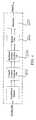
- FIG. 1is a schematic representation of a conventional satellite communication system including a transmitter system (left), a satellite repeater 150 and a receiver system (right).
- the transmitter systemreceives a digital data input 100 after it passes through digital baseband processing 110 .
- the signalis directed to modulator 120 which modulates the digital data onto a carrier.
- Modulated data signalis then converted to the appropriate frequency and filtered by upconverter 130 .
- the data signalis then directed to High Power Amplifier (“HPA”) 140 to amplify the communication signal prior to transmitting the signal from the transponder system antenna 148 to the satellite repeater 150 .
- HPAHigh Power Amplifier
- the signalis received at the satellite repeater 150 as an uplink signal received by antenna 152 .
- the uplink signalis processed through LNA 154 , down converter 155 , filter 156 , amplifier 158 and filter 159 before its transmission through antenna 153 to the receiver system antenna 172 as a downlink signal.
- the downlink signal received through antenna 172is direct downlinked to a LNB converter 174 which amplifies the signal but inherently adds thermal noise.
- the data signalis then input to demodulator 178 at L-band.
- the demodulatorrecovers the originally-transmitted data to provide digital data output 180 .
- the receiving system 170could comprise a low noise amplifier (“LNA”), radio frequency (“RF”) to intermediate frequency (“IF”) down converter and a demodulator that accepts the IF for demodulation.
- LNAlow noise amplifier
- RFradio frequency
- IFintermediate frequency
- any part of the signal transfer chain from transponder system to satellite repeater to receiver system that imparts a change in amplitude or group delay versus frequencywill cause a degradation of the signal. These changes cause a degradation in performance of the demodulation process, and thus, a less reliable system.
- the largest contributors to the degradation of the signalare caused by the group delay of the upconverter and filter 130 and the satellite repeater 150 which adds group delays at each of its filters 156 and 159 .
- Various parts of the transmitter system and satellite repeater 150conventionally introduce significant amplitude distortion as well.
- the amplitude and phase delay distortionis minimized through the bandwidth of the signal being kept narrow enough to occupy only a limited portion of the available transponder bandwidth where the group delay is sufficiently small to only minimally affect the signal.
- Another common approachis to place an analog equalizer in the ground station uplink that is tuned to compensate for this group delay characteristic.
- Analog equalizerscomprise several sections of all-pass filters that cannot remove the excess delay at the edges of the transponder bandwidth, but rather add additional delay in the middle. This is accomplished in a piecewise method by manually tuning all the sections while monitoring the downlink with very expensive test equipment. To tune the various sections is an art rather than a science. It is impossible to completely equalize the channel with this device. Significant residual group delay or amplitude flatness issues will remain and are subject to the typical drift of analog components.
- a satellite communication systemaddress amplitude and group delay versus frequency correction requirements and other limitations by using a digital receiver associated with the modulator for measuring transmitter and repeater amplitude and group delay versus frequency distortions.
- the characteristics of these distortionsare fed to the modulator which calculates an inverse response and, using a complex FIR and IIR filter structure, compensates for the distortions.
- the digital equalizationis performed in the digital domain within the modulator and, hence, is not dependent on the output frequency of the modulator.
- a digital receiveris located at the receive end of the communication link for measuring transmitter and repeater distortions.
- the characteristics of these distortionsare communicated over an external communications link to the modulator which then calculates an inverse response and, using a complex FIR and IIR filter structure and compensates for the distortions.
- the digital equalizationis performed in the digital domain within the modulator and hence is not dependent on the output frequency of the modulator.
- the pre-distortion coefficientsare calculated ahead of time and uploaded to the modulator to modify the spectral output of the system to compensate for the distortion.
- the digital equalizationis performed in the digital domain within the modulator and, hence, is not dependent on the output frequency of the modulator.
- FIG. 1is a schematic representation of a conventional satellite communication system
- FIG. 2is a graph illustrating group delay versus relative frequency of a conventional transponder
- FIG. 3is a schematic representation of a satellite communication system according to a particular implementation of the disclosure.
- FIG. 4is a block diagram of a modulator configured according to a particular implementation of the disclosure.
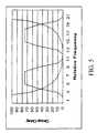
- FIG. 5is a graph illustrating group delay versus relative frequency for multiple carriers on a single transponder system
- FIGS. 6A and 6Bschematically illustrate receive signals through a conventional satellite communication system and a satellite communication system configured with a pre-distortion process.
- FIG. 7illustrates a representation of received signals through a conventional satellite communication system such as that illustrated in FIG. 1 modulated by 8 PSK at 30 Msps;
- FIG. 8illustrates a representation of the received signals shown in FIG. 5 , but processed according to a satellite communication system configured according to an implementation of the disclosure.
- FIG. 9is a graph illustrating a performance comparison of a modulator and demodulator with no degradation, a conventional transponder without an equalizer and a conventional transponder with equalization configured according to a particular implementation of the disclosure for various types of modulation.
- FIG. 2illustrates a representation of the group delay versus relative frequency of a conventional system. This forces large carriers to use only the center portion of the frequency range of the transponder.
- a conventional transponder systemuses only a portion of its available bandwidth capacity because of these limitations. In fact, a conventional transponder system typically uses only 80% of its total capacity.
- FIG. 3is a block diagram of a particular, non-limiting example of an equalizer circuit 200 , particular implementations of which may be referred to as an automatic equalizer (“AutoEQ”) throughout this disclosure.
- Equalizer 200addresses amplitude and group delay versus frequency correction by pre-filtering the digital data input signal 100 with an opposite phase and amplitude as the known transponder system. Because the pre-distortion step is performed at baseband in the digital processing circuitry, it can effectively eliminate the negative effects of the amplifier and filter distortion resulting in a carrier free of distortion at any output IF frequency.
- the amplitude and group delay versus frequency filter function of a satellite communication systemcan be described by the time impulse response of the filter (or combination of filters).
- standard equalizer techniquesto compensate for it. These include, by non-limiting example, minimum mean squared error (MMSE), least mean square (LMS), decision feedback (DFE), and the like.
- MMSEminimum mean squared error
- LMSleast mean square
- DFEdecision feedback
- the equalizerespecially those using DFE type techniques, may be employed in the receiver.
- DFE type equalizer techniquesmay be employed in the receiver.
- implementations applying DFE type equalizer techniques in the receiverare rather simple; relying on the DFE approach to cancel the inter-symbol interference (“ISI”) created by the non-constant group delay as opposed to generating the inverse response as is the case for the transmit equalizer.
- ISIinter-symbol interference
- the receive equalizerwill add noise to the signal and cause degradation from a lower signal to noise ratio.
- the equalizer in the transmitteravoids this problem
- the modulatoris programmed and configured to generate a known pseudorandom noise (“PN”) modulated BPSK signal occupying the same bandwidth as the desired modulated signal to measure the impulse response for the communication channel.
- the receiveruses conventional techniques to demodulate the signal, but also includes a complex PN correlator using the known PN pattern.
- the output of the correlatoris the impulse response of the communication channel, but it is corrupted by noise.
- the result of the computationis mathematically the same except that it contains the uncorrelated noise from the link.
- the signal to noise ratiomay be improved to the point where an accurate, stable impulse response can be computed.
- other data patterns besides a PN patternwill work. A pattern such as a single “one” followed by s string of “zeros” would work, but the PN sequence results in a more uniform output spectrum.
- the satellite communication systemis modeled as a modulated signal with a characteristic impulse response (time response) of S passing through a filter Fe (the equalizer) then passing through a filter Fs (the satellite filter), then being received as a signal that is passed through a Nyquist filter Fn, resulting in a received signal Rrx (the received impulse response).
- the difference between Rrx and Rrefis the result of Fs.
- Implementations of the digital equalizer circuitmay be configured in a variety of different ways depending upon the existing circuitry schemes being configured to include AutoEQ and the needs of a particular application of the equalizer.
- the equalizer for the circuitmay be placed in the digital modulator either before or after the Nyquist filter but before modulation as illustrated in the non-limiting example provided in FIG. 4 . This makes the equalizer independent of modulator output frequency. Conventional analog equalizers are not capable of equalizing independent of modulator output frequency.
- the equalizer in the particular implementations shown in FIGS. 3 and 4each comprise a forward complex FIR digital filter 202 followed by a backward complex IIR digital filter 204 . The output of the backward complex IIR filter 204 is fed to a Nyquist filter 206 and then to the modulator 210 .
- Those of ordinary skill in the artwill understand how to select and construct the components of the circuit from the block diagrams and descriptions provided.
- Non-symmetric group delay variationmay occur when two carriers are placed on a single transponder system as is illustrated through the graph included in FIG. 5 .
- the receivermay be built into the modulator of the transmitter system for measuring transmitter and repeater distortions that are then fed into the modulator to calculate an inverse response.
- the modulatormay then compensate for the distortions which may use a digital equalization performed in the digital domain so it is not dependent on the output frequency of the modulator.
- a digital receivermay be located at the receive end of the communication system for measuring transmitter and repeater distortions which are communicated to the modulator which then calculates an inverse response.
- the modulatormay then compensate for the distortions which may use digital equalization performed in the digital domain so it is not dependent on the output frequency of the modulator.
- pre-distortion coefficientsare calculated ahead of time and uploaded to the modulator to modify the spectral output of the system and compensate for the amplitude versus frequency group delay distortion which may use digital equalization performed in the digital domain so it is not dependent on the output frequency of the modulator.
- the received signalis sampled by the AutoEQ receiver 300 receives amplitude and phase distortion information through the receiver system after the received signal has been received from the satellite antenna 153 , but before the L-band signal is demodulated at demodulator 178 .
- the signalis processed at receiver microprocessor 302 before being fed to the forward complex FIR digital filter 202 with the digitally processed data input signal 100 .
- the equalizer circuitcalculates the amplitude versus frequency group delay correction pre-distortion coefficients and pre-distorts the carrier signal consistent with the pre-distortion coefficients.
- FIGS. 6A and 6Bschematically illustrate a comparison between a receive signal in a conventional satellite communication system ( FIG. 6A ) and a receive signal resulting through a satellite communication system modified with a pre-distortion process configured according to a particular implementation of the disclosure ( FIG. 6B ).
- a transponder induced distortion 410is added to the normal transmit signal 420 when it is received as the conventional receive signal 430 .
- the received signal 430is used as the basis for determining the desired carrier group delay.
- Normal transmit signal 420is equalized by the AutoEQ processed signal 440 to pre-distort the transmit signal, resulting in a much better quality receive signal 450 .
- the negative effects of the transponder and satellite distortioncan be eliminated.
- FIG. 7illustrates conventional satellite communication system received signals modulated by 8 PSK (phase shift keying) at 30 Msps. Specifically, FIG. 7 illustrates pre-equalization eye-pattern distortion. In contrast, FIG. 8 illustrates the received signals of FIG. 7 processed with an automatic equalizer consistent with an implementation of the disclosure. A comparison of FIGS. 7 and 8 illustrates the significance of auto-equalization according to the implementations disclosed herein.
- PSKphase shift keying
- FIG. 9illustrates an example of a performance improvement achieved using AutoEq for 3 types of modulation compared to the performance of a typical transponder system.
- the baseline curves of the modem performance without a transponderare the best that can be attained in a conventional satellite communication system.
- the curves without AutoEQillustrate the degradation the typical transponder causes for QPSK, 8 PSK and 16 PSK carrier examples, respectively.
- the first lines 910 , 912 and 914 on each examplerepresents the ideal performance curve with no transponder or equalizer at all for each of the respective examples.
- the second lines 920 , 922 and 924 on each respective examplerepresents performance with the AutoEQ amplitude and group delay versus frequency correction turned off.
- the third line 930 , 932 and 934 on each respective examplerepresents performance with the AutoEq turned on.
- the curves with AutoEQ turned onshow the performance improvement that AutoEQ provides, nearly matching the best attainable result from the modem nearly to the limits of the transponder system frequency range.
Landscapes
- Engineering & Computer Science (AREA)
- Power Engineering (AREA)
- Computer Networks & Wireless Communication (AREA)
- Signal Processing (AREA)
- Radio Relay Systems (AREA)
- Cable Transmission Systems, Equalization Of Radio And Reduction Of Echo (AREA)
Abstract
Description
S*Fe*Fs*Fn=Rrx
Rref=S*Fn
Claims (19)
Priority Applications (1)
| Application Number | Priority Date | Filing Date | Title |
|---|---|---|---|
| US12/202,513US8233562B2 (en) | 2007-09-05 | 2008-09-02 | System and method for closed-loop signal distortion |
Applications Claiming Priority (2)
| Application Number | Priority Date | Filing Date | Title |
|---|---|---|---|
| US97023907P | 2007-09-05 | 2007-09-05 | |
| US12/202,513US8233562B2 (en) | 2007-09-05 | 2008-09-02 | System and method for closed-loop signal distortion |
Publications (2)
| Publication Number | Publication Date |
|---|---|
| US20090052507A1 US20090052507A1 (en) | 2009-02-26 |
| US8233562B2true US8233562B2 (en) | 2012-07-31 |
Family
ID=40382099
Family Applications (1)
| Application Number | Title | Priority Date | Filing Date |
|---|---|---|---|
| US12/202,513Expired - Fee RelatedUS8233562B2 (en) | 2007-09-05 | 2008-09-02 | System and method for closed-loop signal distortion |
Country Status (1)
| Country | Link |
|---|---|
| US (1) | US8233562B2 (en) |
Cited By (1)
| Publication number | Priority date | Publication date | Assignee | Title |
|---|---|---|---|---|
| US10033568B2 (en) | 2014-07-04 | 2018-07-24 | Ses S.A. | Methods, devices, and computer programs for compensating nonlinearities of a communication channel |
Families Citing this family (5)
| Publication number | Priority date | Publication date | Assignee | Title |
|---|---|---|---|---|
| CN103647595B (en)* | 2013-12-25 | 2017-01-18 | 北京华力创通科技股份有限公司 | Signal transmitting device and method for satellite mobile communication system |
| TWI573414B (en)* | 2015-12-17 | 2017-03-01 | 翌勤通訊股份有限公司 | Repeater system and control signal method thereof |
| US10027404B2 (en) | 2016-01-08 | 2018-07-17 | Global Eagle Entertainment Inc. | Loopback satellite transponder pre-distorter |
| CN106357323A (en)* | 2016-10-08 | 2017-01-25 | 航天恒星科技有限公司 | Satellite channel group delay compensation method and device |
| TWI628927B (en)* | 2017-02-20 | 2018-07-01 | 群聯電子股份有限公司 | Equalizer adjustment method, adaptive equalizer and memory storage device |
Citations (15)
| Publication number | Priority date | Publication date | Assignee | Title |
|---|---|---|---|---|
| US5625893A (en) | 1993-07-26 | 1997-04-29 | Kahn; Leonard R. | Satellite communications system with receiver distortion correction which is controlled by up-link transmission equipment |
| US5860057A (en)* | 1995-03-15 | 1999-01-12 | Hitachi, Ltd. | Satellite communications system and method |
| US6246865B1 (en) | 1997-02-04 | 2001-06-12 | Samsung Electronics Co., Ltd. | Device and method for controlling distortion characteristic of predistorter |
| US6252912B1 (en)* | 1997-12-24 | 2001-06-26 | General Dynamics Government Systems Corporation | Adaptive predistortion system |
| US6266517B1 (en) | 1999-12-30 | 2001-07-24 | Motorola, Inc. | Method and apparatus for correcting distortion in a transmitter |
| US20040028411A1 (en) | 2002-08-07 | 2004-02-12 | Ses-Americom, Incorporated | System and method for transmitting high-bandwidth signals over a satellite communications system |
| US6751266B1 (en) | 1999-06-30 | 2004-06-15 | Harris Corporation | RF transmitter employing linear and non-linear pre-correctors |
| US20040166800A1 (en)* | 2003-02-21 | 2004-08-26 | Feng-Wen Sun | Compensating for non-linearity in an overlaid communication system |
| US6873860B2 (en) | 2000-11-24 | 2005-03-29 | Telefonaktiebolaget Lm Ericsson (Publ) | Base transceiver station with distortion compensation |
| US6879641B2 (en) | 2002-06-13 | 2005-04-12 | Bigband Networks Bas, Inc. | Transmit pre-equalization in a modem environment |
| US6889060B2 (en) | 2001-06-28 | 2005-05-03 | Telecommunications Research Laboratories | Optical fiber based on wireless scheme for wideband multimedia access |
| US20050094752A1 (en) | 2003-11-03 | 2005-05-05 | Frahm Timothy V. | Pre-equalization for low-cost DTV translators |
| US6957044B2 (en) | 2001-03-13 | 2005-10-18 | Tandberg Television Asa | Satellite communication apparatus |
| US20070082617A1 (en) | 2005-10-11 | 2007-04-12 | Crestcom, Inc. | Transceiver with isolation-filter compensation and method therefor |
| US20070153884A1 (en) | 2005-10-13 | 2007-07-05 | Viasat, Inc. | Closed-loop receiver feedback pre-distortion |
- 2008
- 2008-09-02USUS12/202,513patent/US8233562B2/ennot_activeExpired - Fee Related
Patent Citations (15)
| Publication number | Priority date | Publication date | Assignee | Title |
|---|---|---|---|---|
| US5625893A (en) | 1993-07-26 | 1997-04-29 | Kahn; Leonard R. | Satellite communications system with receiver distortion correction which is controlled by up-link transmission equipment |
| US5860057A (en)* | 1995-03-15 | 1999-01-12 | Hitachi, Ltd. | Satellite communications system and method |
| US6246865B1 (en) | 1997-02-04 | 2001-06-12 | Samsung Electronics Co., Ltd. | Device and method for controlling distortion characteristic of predistorter |
| US6252912B1 (en)* | 1997-12-24 | 2001-06-26 | General Dynamics Government Systems Corporation | Adaptive predistortion system |
| US6751266B1 (en) | 1999-06-30 | 2004-06-15 | Harris Corporation | RF transmitter employing linear and non-linear pre-correctors |
| US6266517B1 (en) | 1999-12-30 | 2001-07-24 | Motorola, Inc. | Method and apparatus for correcting distortion in a transmitter |
| US6873860B2 (en) | 2000-11-24 | 2005-03-29 | Telefonaktiebolaget Lm Ericsson (Publ) | Base transceiver station with distortion compensation |
| US6957044B2 (en) | 2001-03-13 | 2005-10-18 | Tandberg Television Asa | Satellite communication apparatus |
| US6889060B2 (en) | 2001-06-28 | 2005-05-03 | Telecommunications Research Laboratories | Optical fiber based on wireless scheme for wideband multimedia access |
| US6879641B2 (en) | 2002-06-13 | 2005-04-12 | Bigband Networks Bas, Inc. | Transmit pre-equalization in a modem environment |
| US20040028411A1 (en) | 2002-08-07 | 2004-02-12 | Ses-Americom, Incorporated | System and method for transmitting high-bandwidth signals over a satellite communications system |
| US20040166800A1 (en)* | 2003-02-21 | 2004-08-26 | Feng-Wen Sun | Compensating for non-linearity in an overlaid communication system |
| US20050094752A1 (en) | 2003-11-03 | 2005-05-05 | Frahm Timothy V. | Pre-equalization for low-cost DTV translators |
| US20070082617A1 (en) | 2005-10-11 | 2007-04-12 | Crestcom, Inc. | Transceiver with isolation-filter compensation and method therefor |
| US20070153884A1 (en) | 2005-10-13 | 2007-07-05 | Viasat, Inc. | Closed-loop receiver feedback pre-distortion |
Cited By (1)
| Publication number | Priority date | Publication date | Assignee | Title |
|---|---|---|---|---|
| US10033568B2 (en) | 2014-07-04 | 2018-07-24 | Ses S.A. | Methods, devices, and computer programs for compensating nonlinearities of a communication channel |
Also Published As
| Publication number | Publication date |
|---|---|
| US20090052507A1 (en) | 2009-02-26 |
Similar Documents
| Publication | Publication Date | Title |
|---|---|---|
| US9071313B2 (en) | Method and apparatus for demodulation of a desired signal in the presence of nonlinear-distorted interference | |
| US9608718B2 (en) | Method and apparatus for demodulation of a desired signal by constellation-independent cancellation of nonlinear-distorted interference | |
| US8160127B2 (en) | Asymmetric multi-channel adaptive equalizer | |
| US8553805B2 (en) | Method and apparatus for subband signal demodulation in a transponder satellite communication link containing a component of relayed interference | |
| US8233562B2 (en) | System and method for closed-loop signal distortion | |
| US20030058959A1 (en) | Combined digital adaptive pre-distorter and pre-equalizer system for modems in link hopping radio networks | |
| US6205170B1 (en) | Transmission/reception unit with bidirectional equalization | |
| US8204455B2 (en) | Techniques for pre-distorting transmitted signals for a transmitter device | |
| US11316716B2 (en) | Radio frequency impairments compensator for broadband quadrature-conversion architectures | |
| EP1371202B1 (en) | Predistortion for correction of non-linearities and group delay in satellite communications | |
| EP2362556B1 (en) | A method and a system with distortion compensation | |
| JP6405153B2 (en) | Transmitter | |
| JP5520858B2 (en) | Amplifier characteristic estimation device, compensator, and transmission device | |
| US10230409B2 (en) | Apparatus and method for reduced computation amplifier gain control | |
| JP2016059026A (en) | Receiver | |
| US10158388B2 (en) | Receiver device and method for non-linear channel compensation | |
| WO1999044343A1 (en) | Quadrature modulator | |
| US20110150131A1 (en) | Apparatus and method for processing digital transmission/reception signals to correct in-band gain flatness | |
| JP7203657B2 (en) | Amplifier characteristic estimation device, compensator, transmission device, and program | |
| JP6937215B2 (en) | Amplifier characteristic estimator, compensator, transmitter, and program | |
| EP1748578A1 (en) | Method and device for repeating isofrequency signals | |
| JPH1065586A (en) | Receiver | |
| WO2002073920A1 (en) | Distortion pre-corrector for communication apparatus | |
| Ishiguro | Post-Compensation of TWTA Nonlinearity for Satellite Communications | |
| JPS6352822B2 (en) |
Legal Events
| Date | Code | Title | Description |
|---|---|---|---|
| AS | Assignment | Owner name:COMTECH EF DATA CORP., ARIZONA Free format text:ASSIGNMENT OF ASSIGNORS INTEREST;ASSIGNOR:EYMANN, STEVEN;REEL/FRAME:021470/0373 Effective date:20080901 | |
| STCF | Information on status: patent grant | Free format text:PATENTED CASE | |
| FPAY | Fee payment | Year of fee payment:4 | |
| AS | Assignment | Owner name:CITIBANK N.A., AS ADMINISTRATIVE AGENT, NEW YORK Free format text:SECURITY AGREEMENT;ASSIGNORS:COMTECH EF DATA CORP.;COMTECH XICOM TECHNOLOGY, INC.;COMTECH MOBILE DATACOM CORPORATION;AND OTHERS;REEL/FRAME:037993/0001 Effective date:20160223 | |
| MAFP | Maintenance fee payment | Free format text:PAYMENT OF MAINTENANCE FEE, 8TH YEAR, LARGE ENTITY (ORIGINAL EVENT CODE: M1552); ENTITY STATUS OF PATENT OWNER: LARGE ENTITY Year of fee payment:8 | |
| FEPP | Fee payment procedure | Free format text:MAINTENANCE FEE REMINDER MAILED (ORIGINAL EVENT CODE: REM.); ENTITY STATUS OF PATENT OWNER: LARGE ENTITY | |
| AS | Assignment | Owner name:COMTECH SATELLITE NETWORK TECHNOLOGIES, INC., ARIZONA Free format text:MERGER AND CHANGE OF NAME;ASSIGNORS:COMTECH EF DATA CORP.;COMTECH XICOM TECHNOLOGY, INC.;COMTECH SATELLITE NETWORK TECHNOLOGIES, INC.;REEL/FRAME:067187/0363 Effective date:20210730 | |
| AS | Assignment | Owner name:TCW ASSET MANAGEMENT COMPANY LLC, AS AGENT, MASSACHUSETTS Free format text:SECURITY INTEREST;ASSIGNOR:COMTECH SATELLITE NETWORK TECHNOLOGIES, INC.;REEL/FRAME:067756/0148 Effective date:20240617 | |
| AS | Assignment | Owner name:TELECOMMUNICATION SYSTEMS, INC., NEW YORK Free format text:RELEASE OF SECURITY INTEREST IN PATENTS AT REEL 037993/FRAME 0001;ASSIGNOR:CITIBANK, N.A., AS ADMINISTRATIVE AGENT;REEL/FRAME:067780/0566 Effective date:20240618 Owner name:MAPLE ACQUISITION LLC, MARYLAND Free format text:RELEASE OF SECURITY INTEREST IN PATENTS AT REEL 037993/FRAME 0001;ASSIGNOR:CITIBANK, N.A., AS ADMINISTRATIVE AGENT;REEL/FRAME:067780/0566 Effective date:20240618 Owner name:COMTECH XICOM TECHNOLOGY, INC., CALIFORNIA Free format text:RELEASE OF SECURITY INTEREST IN PATENTS AT REEL 037993/FRAME 0001;ASSIGNOR:CITIBANK, N.A., AS ADMINISTRATIVE AGENT;REEL/FRAME:067780/0566 Effective date:20240618 Owner name:COMTECH SYSTEMS, INC., FLORIDA Free format text:RELEASE OF SECURITY INTEREST IN PATENTS AT REEL 037993/FRAME 0001;ASSIGNOR:CITIBANK, N.A., AS ADMINISTRATIVE AGENT;REEL/FRAME:067780/0566 Effective date:20240618 Owner name:COMTECH SATELLITE NETWORK TECHNOLOGIES, INC., ARIZONA Free format text:RELEASE OF SECURITY INTEREST IN PATENTS AT REEL 037993/FRAME 0001;ASSIGNOR:CITIBANK, N.A., AS ADMINISTRATIVE AGENT;REEL/FRAME:067780/0566 Effective date:20240618 Owner name:COMTECH MOBILE DATACOM LLC, MARYLAND Free format text:RELEASE OF SECURITY INTEREST IN PATENTS AT REEL 037993/FRAME 0001;ASSIGNOR:CITIBANK, N.A., AS ADMINISTRATIVE AGENT;REEL/FRAME:067780/0566 Effective date:20240618 Owner name:COMTECH EF DATA CORP., ARIZONA Free format text:RELEASE OF SECURITY INTEREST IN PATENTS AT REEL 037993/FRAME 0001;ASSIGNOR:CITIBANK, N.A., AS ADMINISTRATIVE AGENT;REEL/FRAME:067780/0566 Effective date:20240618 Owner name:COMTECH TELECOMMUNICATIONS CORP., NEW YORK Free format text:RELEASE OF SECURITY INTEREST IN PATENTS AT REEL 037993/FRAME 0001;ASSIGNOR:CITIBANK, N.A., AS ADMINISTRATIVE AGENT;REEL/FRAME:067780/0566 Effective date:20240618 | |
| LAPS | Lapse for failure to pay maintenance fees | Free format text:PATENT EXPIRED FOR FAILURE TO PAY MAINTENANCE FEES (ORIGINAL EVENT CODE: EXP.); ENTITY STATUS OF PATENT OWNER: LARGE ENTITY | |
| STCH | Information on status: patent discontinuation | Free format text:PATENT EXPIRED DUE TO NONPAYMENT OF MAINTENANCE FEES UNDER 37 CFR 1.362 | |
| FP | Lapsed due to failure to pay maintenance fee | Effective date:20240731 |