US8233555B2 - Time varying delay diversity of OFDM - Google Patents
Time varying delay diversity of OFDMDownload PDFInfo
- Publication number
- US8233555B2 US8233555B2US11/078,176US7817605AUS8233555B2US 8233555 B2US8233555 B2US 8233555B2US 7817605 AUS7817605 AUS 7817605AUS 8233555 B2US8233555 B2US 8233555B2
- Authority
- US
- United States
- Prior art keywords
- symbol
- delay period
- samples
- symbols
- antenna
- Prior art date
- Legal status (The legal status is an assumption and is not a legal conclusion. Google has not performed a legal analysis and makes no representation as to the accuracy of the status listed.)
- Active, expires
Links
- 238000000034methodMethods0.000claimsabstractdescription45
- 125000004122cyclic groupChemical group0.000claimsdescription43
- 230000006870functionEffects0.000claimsdescription27
- 230000005540biological transmissionEffects0.000claimsdescription26
- 230000015654memoryEffects0.000claimsdescription25
- 238000004891communicationMethods0.000claimsdescription19
- 230000003111delayed effectEffects0.000claimsdescription18
- 230000010363phase shiftEffects0.000description38
- 238000010586diagramMethods0.000description13
- 238000012545processingMethods0.000description11
- 230000004044responseEffects0.000description11
- 230000008569processEffects0.000description8
- 239000013598vectorSubstances0.000description8
- 239000011159matrix materialSubstances0.000description7
- 230000001934delayEffects0.000description6
- 238000013507mappingMethods0.000description5
- 230000000295complement effectEffects0.000description4
- 238000005562fadingMethods0.000description4
- 230000001143conditioned effectEffects0.000description3
- 230000008901benefitEffects0.000description2
- 230000002939deleterious effectEffects0.000description2
- 238000013461designMethods0.000description2
- 230000001066destructive effectEffects0.000description2
- 230000000694effectsEffects0.000description2
- 101000863856Homo sapiens Shiftless antiviral inhibitor of ribosomal frameshifting proteinProteins0.000description1
- 230000003044adaptive effectEffects0.000description1
- 239000000654additiveSubstances0.000description1
- 230000000996additive effectEffects0.000description1
- 239000000969carrierSubstances0.000description1
- 230000008859changeEffects0.000description1
- 239000002131composite materialSubstances0.000description1
- 230000008878couplingEffects0.000description1
- 238000010168coupling processMethods0.000description1
- 238000005859coupling reactionMethods0.000description1
- 230000001419dependent effectEffects0.000description1
- 239000006185dispersionSubstances0.000description1
- 238000012986modificationMethods0.000description1
- 230000004048modificationEffects0.000description1
- 230000009467reductionEffects0.000description1
- 230000008054signal transmissionEffects0.000description1
- 230000003068static effectEffects0.000description1
Images


Classifications
- H—ELECTRICITY
- H04—ELECTRIC COMMUNICATION TECHNIQUE
- H04B—TRANSMISSION
- H04B7/00—Radio transmission systems, i.e. using radiation field
- H04B7/02—Diversity systems; Multi-antenna system, i.e. transmission or reception using multiple antennas
- H04B7/04—Diversity systems; Multi-antenna system, i.e. transmission or reception using multiple antennas using two or more spaced independent antennas
- H04B7/0413—MIMO systems
- H04B7/0417—Feedback systems
- H—ELECTRICITY
- H04—ELECTRIC COMMUNICATION TECHNIQUE
- H04B—TRANSMISSION
- H04B7/00—Radio transmission systems, i.e. using radiation field
- H04B7/02—Diversity systems; Multi-antenna system, i.e. transmission or reception using multiple antennas
- H04B7/04—Diversity systems; Multi-antenna system, i.e. transmission or reception using multiple antennas using two or more spaced independent antennas
- H04B7/06—Diversity systems; Multi-antenna system, i.e. transmission or reception using multiple antennas using two or more spaced independent antennas at the transmitting station
- H04B7/0613—Diversity systems; Multi-antenna system, i.e. transmission or reception using multiple antennas using two or more spaced independent antennas at the transmitting station using simultaneous transmission
- H04B7/0615—Diversity systems; Multi-antenna system, i.e. transmission or reception using multiple antennas using two or more spaced independent antennas at the transmitting station using simultaneous transmission of weighted versions of same signal
- H04B7/0619—Diversity systems; Multi-antenna system, i.e. transmission or reception using multiple antennas using two or more spaced independent antennas at the transmitting station using simultaneous transmission of weighted versions of same signal using feedback from receiving side
- H04B7/0621—Feedback content
- H04B7/0632—Channel quality parameters, e.g. channel quality indicator [CQI]
- H—ELECTRICITY
- H04—ELECTRIC COMMUNICATION TECHNIQUE
- H04B—TRANSMISSION
- H04B7/00—Radio transmission systems, i.e. using radiation field
- H04B7/02—Diversity systems; Multi-antenna system, i.e. transmission or reception using multiple antennas
- H04B7/04—Diversity systems; Multi-antenna system, i.e. transmission or reception using multiple antennas using two or more spaced independent antennas
- H04B7/06—Diversity systems; Multi-antenna system, i.e. transmission or reception using multiple antennas using two or more spaced independent antennas at the transmitting station
- H04B7/0613—Diversity systems; Multi-antenna system, i.e. transmission or reception using multiple antennas using two or more spaced independent antennas at the transmitting station using simultaneous transmission
- H04B7/0667—Diversity systems; Multi-antenna system, i.e. transmission or reception using multiple antennas using two or more spaced independent antennas at the transmitting station using simultaneous transmission of delayed versions of same signal
- H04B7/0671—Diversity systems; Multi-antenna system, i.e. transmission or reception using multiple antennas using two or more spaced independent antennas at the transmitting station using simultaneous transmission of delayed versions of same signal using different delays between antennas
- H—ELECTRICITY
- H04—ELECTRIC COMMUNICATION TECHNIQUE
- H04B—TRANSMISSION
- H04B7/00—Radio transmission systems, i.e. using radiation field
- H04B7/02—Diversity systems; Multi-antenna system, i.e. transmission or reception using multiple antennas
- H04B7/04—Diversity systems; Multi-antenna system, i.e. transmission or reception using multiple antennas using two or more spaced independent antennas
- H04B7/06—Diversity systems; Multi-antenna system, i.e. transmission or reception using multiple antennas using two or more spaced independent antennas at the transmitting station
- H04B7/0613—Diversity systems; Multi-antenna system, i.e. transmission or reception using multiple antennas using two or more spaced independent antennas at the transmitting station using simultaneous transmission
- H04B7/0682—Diversity systems; Multi-antenna system, i.e. transmission or reception using multiple antennas using two or more spaced independent antennas at the transmitting station using simultaneous transmission using phase diversity (e.g. phase sweeping)
- H—ELECTRICITY
- H04—ELECTRIC COMMUNICATION TECHNIQUE
- H04L—TRANSMISSION OF DIGITAL INFORMATION, e.g. TELEGRAPHIC COMMUNICATION
- H04L1/00—Arrangements for detecting or preventing errors in the information received
- H04L1/004—Arrangements for detecting or preventing errors in the information received by using forward error control
- H04L1/0056—Systems characterized by the type of code used
- H04L1/0071—Use of interleaving
- H—ELECTRICITY
- H04—ELECTRIC COMMUNICATION TECHNIQUE
- H04L—TRANSMISSION OF DIGITAL INFORMATION, e.g. TELEGRAPHIC COMMUNICATION
- H04L1/00—Arrangements for detecting or preventing errors in the information received
- H04L1/02—Arrangements for detecting or preventing errors in the information received by diversity reception
- H04L1/06—Arrangements for detecting or preventing errors in the information received by diversity reception using space diversity
- H04L1/0618—Space-time coding
- H—ELECTRICITY
- H04—ELECTRIC COMMUNICATION TECHNIQUE
- H04L—TRANSMISSION OF DIGITAL INFORMATION, e.g. TELEGRAPHIC COMMUNICATION
- H04L27/00—Modulated-carrier systems
- H04L27/26—Systems using multi-frequency codes
- H04L27/2601—Multicarrier modulation systems
- H04L27/2602—Signal structure
- H—ELECTRICITY
- H04—ELECTRIC COMMUNICATION TECHNIQUE
- H04L—TRANSMISSION OF DIGITAL INFORMATION, e.g. TELEGRAPHIC COMMUNICATION
- H04L27/00—Modulated-carrier systems
- H04L27/26—Systems using multi-frequency codes
- H04L27/2601—Multicarrier modulation systems
- H04L27/2626—Arrangements specific to the transmitter only
- H04L27/2627—Modulators
- H04L27/2628—Inverse Fourier transform modulators, e.g. inverse fast Fourier transform [IFFT] or inverse discrete Fourier transform [IDFT] modulators
- H—ELECTRICITY
- H04—ELECTRIC COMMUNICATION TECHNIQUE
- H04L—TRANSMISSION OF DIGITAL INFORMATION, e.g. TELEGRAPHIC COMMUNICATION
- H04L27/00—Modulated-carrier systems
- H04L27/26—Systems using multi-frequency codes
- H04L27/2601—Multicarrier modulation systems
- H04L27/2626—Arrangements specific to the transmitter only
- H04L27/2627—Modulators
- H04L27/2634—Inverse fast Fourier transform [IFFT] or inverse discrete Fourier transform [IDFT] modulators in combination with other circuits for modulation
- H—ELECTRICITY
- H04—ELECTRIC COMMUNICATION TECHNIQUE
- H04B—TRANSMISSION
- H04B7/00—Radio transmission systems, i.e. using radiation field
- H04B7/02—Diversity systems; Multi-antenna system, i.e. transmission or reception using multiple antennas
- H04B7/04—Diversity systems; Multi-antenna system, i.e. transmission or reception using multiple antennas using two or more spaced independent antennas
- H04B7/06—Diversity systems; Multi-antenna system, i.e. transmission or reception using multiple antennas using two or more spaced independent antennas at the transmitting station
- H04B7/0613—Diversity systems; Multi-antenna system, i.e. transmission or reception using multiple antennas using two or more spaced independent antennas at the transmitting station using simultaneous transmission
- H04B7/0667—Diversity systems; Multi-antenna system, i.e. transmission or reception using multiple antennas using two or more spaced independent antennas at the transmitting station using simultaneous transmission of delayed versions of same signal
- H04B7/0673—Diversity systems; Multi-antenna system, i.e. transmission or reception using multiple antennas using two or more spaced independent antennas at the transmitting station using simultaneous transmission of delayed versions of same signal using feedback from receiving side
- H—ELECTRICITY
- H04—ELECTRIC COMMUNICATION TECHNIQUE
- H04L—TRANSMISSION OF DIGITAL INFORMATION, e.g. TELEGRAPHIC COMMUNICATION
- H04L1/00—Arrangements for detecting or preventing errors in the information received
- H04L1/0001—Systems modifying transmission characteristics according to link quality, e.g. power backoff
- H04L1/0002—Systems modifying transmission characteristics according to link quality, e.g. power backoff by adapting the transmission rate
- H04L1/0003—Systems modifying transmission characteristics according to link quality, e.g. power backoff by adapting the transmission rate by switching between different modulation schemes
- H—ELECTRICITY
- H04—ELECTRIC COMMUNICATION TECHNIQUE
- H04L—TRANSMISSION OF DIGITAL INFORMATION, e.g. TELEGRAPHIC COMMUNICATION
- H04L1/00—Arrangements for detecting or preventing errors in the information received
- H04L1/0001—Systems modifying transmission characteristics according to link quality, e.g. power backoff
- H04L1/0009—Systems modifying transmission characteristics according to link quality, e.g. power backoff by adapting the channel coding
- H—ELECTRICITY
- H04—ELECTRIC COMMUNICATION TECHNIQUE
- H04L—TRANSMISSION OF DIGITAL INFORMATION, e.g. TELEGRAPHIC COMMUNICATION
- H04L1/00—Arrangements for detecting or preventing errors in the information received
- H04L1/0001—Systems modifying transmission characteristics according to link quality, e.g. power backoff
- H04L1/0023—Systems modifying transmission characteristics according to link quality, e.g. power backoff characterised by the signalling
- H04L1/0026—Transmission of channel quality indication
- H—ELECTRICITY
- H04—ELECTRIC COMMUNICATION TECHNIQUE
- H04L—TRANSMISSION OF DIGITAL INFORMATION, e.g. TELEGRAPHIC COMMUNICATION
- H04L25/00—Baseband systems
- H04L25/02—Details ; arrangements for supplying electrical power along data transmission lines
- H04L25/0202—Channel estimation
- H04L25/0224—Channel estimation using sounding signals
- H—ELECTRICITY
- H04—ELECTRIC COMMUNICATION TECHNIQUE
- H04L—TRANSMISSION OF DIGITAL INFORMATION, e.g. TELEGRAPHIC COMMUNICATION
- H04L27/00—Modulated-carrier systems
- H04L27/26—Systems using multi-frequency codes
- H04L27/2601—Multicarrier modulation systems
- H04L27/2602—Signal structure
- H04L27/2605—Symbol extensions, e.g. Zero Tail, Unique Word [UW]
- H04L27/2607—Cyclic extensions
- H—ELECTRICITY
- H04—ELECTRIC COMMUNICATION TECHNIQUE
- H04L—TRANSMISSION OF DIGITAL INFORMATION, e.g. TELEGRAPHIC COMMUNICATION
- H04L27/00—Modulated-carrier systems
- H04L27/26—Systems using multi-frequency codes
- H04L27/2601—Multicarrier modulation systems
- H04L27/2647—Arrangements specific to the receiver only
- H—ELECTRICITY
- H04—ELECTRIC COMMUNICATION TECHNIQUE
- H04W—WIRELESS COMMUNICATION NETWORKS
- H04W52/00—Power management, e.g. Transmission Power Control [TPC] or power classes
- H04W52/04—Transmission power control [TPC]
- H04W52/38—TPC being performed in particular situations
- H04W52/42—TPC being performed in particular situations in systems with time, space, frequency or polarisation diversity
Definitions
- the present documentrelates generally to wireless communication, and amongst other things to, signal transmission in multi-antenna system.
- an RF modulated signal from a transmittermay reach a receiver via a number of propagation paths.
- the characteristics of the propagation pathstypically vary over time due to a number of factors such as fading and multipath.
- multiple transmit and receive antennasmay be used.
- a multiple-input multiple-output (MIMO) communication systememploys multiple (N T ) transmit antennas and multiple (N R ) receive antennas for data transmission.
- a MIMO channel formed by the N T transmit and N R receive antennasmay be decomposed into N S independent channels, with N S ⁇ min ⁇ N T , N R ⁇ .
- Each of the N S independent channelsmay also be referred to as a spatial subchannel (or a transmission channel) of the MIMO channel and corresponds to a dimension.
- the propagation paths between the transmit and receive antennasare linearly independent (i.e., a transmission on one path is not formed as a linear combination of the transmissions on the other paths), which is generally true to at least an extent, then the likelihood of correctly receiving a data transmission increases as the number of antennas increases. Generally, diversity increases and performance improves as the number of transmit and receive antennas increases
- transmit diversity techniquemay be utilized.
- Many transmit diversity techniqueshave been explored.
- One such techniqueis transmit delay diversity.
- transmit delay diversitya transmitter utilizes two antennas that transmit the same signal, with the second antenna transmitting a delayed replica of that transmitted by the first antenna.
- the second antennacreates diversity by establishing a second set of independent multipath elements that may be collected at the receiver. If the multipath generated by the first transmitter fades, the multipath generated by the second transmitter may not, in which case an acceptable Signal-To-Noise Ratio (SNR) will be maintained at the receiver.
- SNRSignal-To-Noise Ratio
- This techniqueis easy to implement, because only the composite TX 0 +TX 1 channel is estimated at the receiver.
- the biggest drawback to transmit delay diversityis that it increases the effective delay spread of the channel, and can perform poorly when the multipath introduced by the second antenna falls upon, and interacts destructively with, the multipath of the first antenna, thereby reducing the overall level of diversity.
- a cyclic delayis one where the samples of each symbol of the n i symbols are shifted in the order in which they are transmitted as part of the symbol. Those samples that are beyond the effective part of the symbol are transmitted in the beginning of that symbol.
- a prefixis pre-pended to each sample that fixes a delay, or order, for transmitting the sample from the specific antenna as part of the symbol.
- the cyclic delaysallow for longer delays, however, which would otherwise be limited to fractions of the guard interval period to avoid inter-symbol interference.
- a cyclic delay diversity schememay introduce frequency selectivity in the channel and hence may provide diversity benefit for flat channels. It does not provide, however, any time diversity when the channel is not in and of itself time selective. For example, if two transmit antennas are in slow fading or static channels, the cyclic shift ⁇ m may be such that the two channels, e.g. H 1 (n) and H 2 (n), add up destructively (or constructively) all the time.
- a method for providing transmission diversitycomprises providing, to a first antenna, a first symbol after a first delay period, providing, to the first antenna, a second symbol after a second delay period that is different than the first delay period, and providing, to the first antenna, a third symbol after a third delay period that is different than the first delay period and the second delay period.
- a transmittercomprises at least two antennas, a modulator, and a delay circuit that delays symbols output from the modulator to the antenna by a delay period that varies over time.
- a wireless transmittercomprises at least two antennas and a that stores a plurality of symbols each comprising a plurality of samples, wherein the memory outputs the plurality of samples of a first symbol after a first delay to one antenna of the at least two antennas and a second symbol of the plurality of symbols after a second delay to the one antenna.
- the first delay and the second delayare different.
- a transmittercomprises at least three antennas, a modulator, a first delay circuit coupled between the modulator and one of the at least two antennas, the first delay circuit delaying symbols output from the modulator to the antenna by a delay period that varies over time, and a second delay circuit coupled between the modulator and another of the at least two antennas, the first delay circuit delaying symbols output from the modulator to the another antenna by a another delay period that varies over time.
- the another delay period and the delay periodare different.
- a method for providing transmission diversity in a multi-channel communication systemcomprises applying a first phase shift to a first symbol to be transmitted on a first antenna and applying a second phase shift, different than the first phase shift, to the first symbol to be transmitted on a second antenna.
- a transmittercomprises at least two antennas, a modulator, and a phase shift that applies a phase shift to symbols output by the modulator to the antenna by a phase shift that varies over time.
- FIG. 1illustrates a block diagram of an embodiment of a transmitter system and a receiver system in a MIMO system
- FIG. 2illustrates a block diagram of an embodiment of a transmitter unit that provides time-varying delay diversity
- FIG. 3illustrates an embodiment of a time varying delay applied to symbols transmitted from a same antenna
- FIG. 4illustrates an embodiment of a time varying delay applied to a symbol transmitted on multiple antennas
- FIG. 5illustrates a block diagram of another embodiment of a transmitter unit that provides time-varying delay diversity
- FIG. 6illustrates a block diagram of an embodiment of a receiver unit capable of utilizing time-varying delay diversity
- FIG. 7illustrates a block diagram of an embodiment of a delay element
- FIG. 8illustrates a flow chart of an embodiment of a method for providing time-varying diversity
- FIG. 9illustrates a block diagram of a further embodiment of a transmitter unit that provides time-varying delay diversity.
- FIG. 10illustrates a flow chart of a further embodiment of a method for providing time-varying diversity.
- Multi-channel communication systemsinclude multiple-input multiple-output (MIMO) communication systems, orthogonal frequency division multiplexing (OFDM) communication systems, MIMO systems that employ OFDM (i.e., MIMO-OFDM systems), and other types of transmissions.
- MIMOmultiple-input multiple-output
- OFDMorthogonal frequency division multiplexing
- MIMO-OFDM systemsMIMO systems that employ OFDM
- other types of transmissionsi.e., OFDM-OFDM systems
- a MIMO systememploys multiple (N T ) transmit antennas and multiple (N R ) receive antennas for data transmission.
- a MIMO channel formed by the N T transmit and N R receive antennasmay be decomposed into N S independent channels, with N S ⁇ min ⁇ N T , N R ⁇ .
- Each of the N S independent channelsmay also be referred to as a spatial subchannel (or transmission channel) of the MIMO channel.
- the number of spatial subchannelsis determined by the number of eigenmodes for the MIMO channel, which in turn is dependent on a channel response matrix, H, that describes the response between the N T transmit and N R receive antennas.
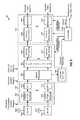
- FIG. 1is a block diagram of an embodiment of a transmitter system 110 and a receiver system 150 in a MIMO system 100 .
- traffic data for a number of data streamsis provided from a data source 112 to a transmit (TX) data processor 114 .
- TX data processor 114formats, codes, and interleaves the traffic data for each data stream based on a particular coding scheme selected for that data stream to provide coded data.
- the coded data for each data streammay be multiplexed with pilot data using, for example, time division multiplexing (TDM) or code division multiplexing (CDM).
- the pilot datais typically a known data pattern that is processed in a known manner (if at all), and may be used at the receiver system to estimate the channel response.
- the multiplexed pilot and coded data for each data streamis then modulated (i.e., symbol mapped) based on a particular modulation scheme (e.g., BPSK, QSPK, M-PSK, or M-QAM) selected for that data stream to provide modulation symbols.
- the data rate, coding, and modulation for each data streammay be determined by controls provided by a processor 130 .
- TX MIMO processor 120may further process the modulation symbols (e.g., for OFDM).
- TX MIMO processor 120then provides N T modulation symbol streams to N T transmitters (TMTR) 122 a through 122 t .
- TMTRN T transmitters
- Each transmitter 122receives and processes a respective symbol stream to provide one or more analog signals, and further conditions (e.g., amplifies, filters, and upconverts) the analog signals to provide a modulated signal suitable for transmission over the MIMO channel.
- N T modulated signals from transmitters 122 a through 122 tare then transmitted from N T antennas 124 a through 124 t , respectively.
- the transmitted modulated signalsare received by N R antennas 152 a through 152 r , and the received signal from each antenna 152 is provided to a respective receiver (RCVR) 154 .
- Each receiver 154conditions (e.g., filters, amplifies, and downconverts) a respective received signal, digitizes the conditioned signal to provide samples, and further processes the samples to provide a corresponding “received” symbol stream.
- An RX MIMO/data processor 160then receives and processes the N R received symbol streams from N R receivers 154 based on a particular receiver processing technique to provide N T “detected” symbol streams.
- the processing by RX MIMO/data processor 160is described in further detail below.
- Each detected symbol streamincludes symbols that are estimates of the modulation symbols transmitted for the corresponding data stream.
- RX MIMO/data processor 160then demodulates, deinterleaves, and decodes each detected symbol stream to recover the traffic data for the data stream.
- the processing by RX MIMO/data processor 160is complementary to that performed by TX MIMO processor 120 and TX data processor 114 at transmitter system 110 .
- RX MIMO processor 160may derive an estimate of the channel response between the N T transmit and N R receive antennas, e.g., based on the pilot multiplexed with the traffic data. The channel response estimate may be used to perform space or space/time processing at the receiver.
- RX MIMO processor 160may further estimate the signal-to-noise-and-interference ratios (SNRs) of the detected symbol streams, and possibly other channel characteristics, and provides these quantities to a processor 170 .
- SNRssignal-to-noise-and-interference ratios
- RX MIMO/data processor 160 or processor 170may further derive an estimate of the “operating” SNR for the system, which is indicative of the conditions of the communication link.
- Processor 170then provides channel state information (CSI), which may comprise various types of information regarding the communication link and/or the received data stream.
- CSIchannel state information
- the CSImay comprise only the operating SNR.
- the CSIis then processed by a TX data processor 178 , modulated by a modulator 180 , conditioned by transmitters 154 a through 154 r , and transmitted back to transmitter system 110 .
- the modulated signals from receiver system 150are received by antennas 124 , conditioned by receivers 122 , demodulated by a demodulator 140 , and processed by a RX data processor 142 to recover the CSI reported by the receiver system.
- the reported CSIis then provided to processor 130 and used to (1) determine the data rates and coding and modulation schemes to be used for the data streams and (2) generate various controls for TX data processor 114 and TX MIMO processor 120 .
- Processors 130 and 170direct the operation at the transmitter and receiver systems that they are coupled with including the appropriate transmit and receive data processors.
- Memories 132 and 172provide storage for program codes and data used by processors 130 and 170 , respectively.
- receiver processing techniquesmay be used to process the N R received signals to detect the N T transmitted symbol streams. These receiver processing techniques may be grouped into two primary categories:
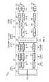
- FIG. 2is a block diagram of a portion of a transmitter unit 200 , which may be an embodiment of the transmitter portion of a transmitter system, e.g. such as transmitter system 110 in FIG. 1 .
- a separate data rate and coding and modulation schememay be used for each of the N T data streams to be transmitted on the N T transmit antennas (i.e., separate coding and modulation on a per-antenna basis).
- the specific data rate and coding and modulation schemes to be used for each transmit antennamay be determined based on controls provided by processor 130 , and the data rates may be determined as described above.
- Transmitter unit 200includes, in one embodiment, a transmit data processor 202 that receives, codes, and modulates each data stream in accordance with a separate coding and modulation scheme to provide modulation symbols and transmit MIMO Transmit data processor 202 and transmit data processor 204 are one embodiment of transmit data processor 114 and transmit MIMO processor 120 , respectively, of FIG. 1 .
- transmit data processor 202includes demultiplexer 210 , N T encoders 212 a through 212 t , and N T channel interleavers 214 a through 214 t (i.e., one set of demultiplexers, encoders, and channel interleavers for each transmit antenna).
- Demultiplexer 210demultiplexes data (i.e., the information bits) into N T data streams for the N T transmit antennas to be used for data transmission.
- the N T data streamsmay be associated with different data rates, as determined by rate control functionality, which in one embodiment may be provided by processor 130 or 170 ( FIG. 1 ). Each data stream is provided to a respective encoder 212 a through 212 t.
- Each encoder 212 a through 212 treceives and codes a respective data stream based on the specific coding scheme selected for that data stream to provide coded bits.
- the codingmay be used to increase the reliability of data transmission.
- the coding schememay include in one embodiment any combination of cyclic redundancy check (CRC) coding, convolutional coding, Turbo coding, block coding, or the like.
- CRCcyclic redundancy check
- the coded bits from each encoder 212 a through 212 tare then provided to a respective channel interleaver 214 a through 214 t , which interleaves the coded bits based on a particular interleaving scheme.
- the interleavingprovides time diversity for the coded bits, permits the data to be transmitted based on an average SNR for the transmission channels used for the data stream, combats fading, and further removes correlation between coded bits used to form each modulation symbol.
- each channel interleaver 214 a through 214 tare provided to a respective symbol mapping block 222 a through 222 t , of transmit MIMO processor 204 , which maps these bits to form modulation symbols.
- each symbol mapping block 222 a through 222 tThe particular modulation scheme to be implemented by each symbol mapping block 222 a through 222 t is determined by the modulation control provided by processor 130 .
- Each symbol mapping block 222 a through 222 tgroups sets of q j coded and interleaved bits to form non-binary symbols, and further maps each non-binary symbol to a specific point in a signal constellation corresponding to the selected modulation scheme (e.g., QPSK, M-PSK, M-QAM, or some other modulation scheme).
- Symbol mapping blocks 222 a through 222 tthen provide N T streams of modulation symbols.
- transmit MIMO processor 204also includes a modulator 224 and inverse Fast Fourier transform (IFFT) block 226 a through 226 t , along with symbol mapping blocks 222 a through 222 t .
- Modulator 224modulates the samples to form the modulation symbols for the N T streams on the proper subbands and transmit antennas.
- modulator 224provides each of the N T symbol streams at a proscribed power level.
- modulator 224may modulate symbols according to a hopping sequence controlled by a processor, e.g. processor 130 or 170 .
- the frequencies with which the N T symbol streams are modulatedmay vary for each group or block of symbols, frame, or portion of a frame of a transmission cycle.
- Each IFFT block 226 a through 226 treceives a respective modulation symbol stream from modulator 224 .
- Each IFFT block 226 a through 226 tgroups sets of N F modulation symbols to form corresponding modulation symbol vectors, and converts each modulation symbol vector into its time-domain representation (which is referred to as an OFDM symbol) using the inverse fast Fourier transform.
- IFFT blocks 226 a through 226 tmay be designed to perform the inverse transform on any number of frequency subchannels (e.g., 8, 16, 32, . . . , N F ,).
- Each time-domain representation of the modulation symbol vector generated by IFFT blocks 226 a through 226 tis provided to an associated cyclic prefix generator 228 a through 228 t .
- the cyclic prefix generators 228 a through 228 tpre-pending a prefix of a fixed number of samples, which are generally a number of samples from the end of the OFDM symbol, to the N S samples that constitute an OFDM symbol to form a corresponding transmission symbol.
- the prefixis designed to improve performance against deleterious path effects such as channel dispersion caused by frequency selective fading.
- Cyclic prefix generators 228 a through 228 tthen provide a stream of transmission symbols to an associated delay element 230 a through 230 t - 1 .
- Each delay element 230 a through 230 t - 1provides a delay to each symbol that is output from cyclic prefix generators 228 a through 228 t .
- the delay provided by each delay element 230 a through 230 t - 1varies in time. In one embodiment, this delay is such that the delay varies between consecutive symbols output by the cyclic prefix generator or consecutive symbols that are to be consecutively transmitted from the transmitter unit 200 .
- the delaymay vary between groups of two, three, four, or more symbols with each symbol within the group having a same delay.
- all of the symbols in a frame or burst periodwould have a same delay with each frame or burst period having a different delay for each symbol than a preceding or following frame or burst period.
- each delay element 230 a through 230 t - 1is different than the delay provided by each other delay element.
- FIG. 2depicts that cyclic prefix generator 228 a is not coupled to a delay element, other embodiments may provide a delay element to the output of each of the cyclic prefix generators 228 a through 228 t.
- the symbols output by delay elements 230 a through 230 t - 1are provided to an associated transmitter 232 a through 232 t which causes the symbols to be transmitted by antennas 232 a through 232 t according to the delay provided by delay elements 230 a through 230 t - 1 .
- the i-th OFDM symbolis transmitted as a transmitted symbol from antenna m according a delay of Eq. 2:
- H m (i,n)is the channel n-th discrete Fourier Transform (DFT) coefficient for the channel impulse response from the m-th transmitting antenna to the receiving antenna.
- DFTdiscrete Fourier Transform
- time varying delaycan introduce both frequency selectivity and time selectivity into the channel that may be utilized to improve performance. For example, by using time varying delay for transmission symbols across different sub-carriers and different OFDM symbols, both the time selectivity and frequency selectivity can simultaneously be provided. Moreover, in the case of transmission to multiple users, the time variation of the channel that is provided by varying the delay for symbols can be exploited to provide diversity gains to each of the multiple users, since each user's receiver will have different channel conditions than each other user's receiver.
- the delay ⁇ m (i)may be changed in a linear fashion with time with each consecutive, or group of consecutive symbols, being delayed by n* ⁇ samples, where ⁇ is a constant and n varying from 0, 1, . . . , N ⁇ 1, where N is the number of symbols in a frame, burst period, or symbol stream.
- the delay ⁇ m (i)may be a random delay, based upon a pseudo random sequence, with respect to an adjacent channel, i.e. antenna, of the N T antennas, a preceding and/or following symbol.
- the delaymay be varied by f(x) where f is a function such as a sine, cosine, or other time varying function, and x varies from 0, 1, . . . , N ⁇ 1 or some multiples thereof, where N is the number of symbols in a frame, burst period, or symbol stream.
- the delaymay also be changed based on feedback information, in which case the receiver sends back a channel quality indicator that describes the overall channel conditions and ⁇ m (i) is changed to improve the overall quality.
- Symbols S 1 , S 2 , S 3 , and S 4are generated to be transmitted during consecutive time slots T 1 , T 2 , T 3 , and T 4 respectively.
- Each symbol S 1 , S 2 , S 3 , and S 4comprises nine samples N S1 , N S2 , N S3 , N S4 , N S5 , N S6 , N S7 , N S8 , N S9 , and a two-sample cyclic prefix N C1 and N C2 , which are samples N S8 , and N S9 respectively.
- each samplemay be different for each of the symbols.
- the samples N S1 , N S2 , N S3 , N S4 , N S5 , N S6 , N S7 , N S8 , N S9are to be combined to form symbol S 1 in the order of N S1 , N S2 , N S3 , N S4 , N S5 , N S6 , N S7 , N S8 , N S9 .
- the delay elemente.g. delay element 230 a , then provides a delay to the symbol S 1 , S 2 , S 3 , and S 4 that are transmitted from the same antenna.
- the delay for symbol S 1is one sample period t 1 .
- the next symbol S 2which is to be transmitted on the same antenna immediately after symbol S 1 , is delayed by two sample periods t 1 and t 2 .
- the next symbol S 3which is to be transmitted on the same antenna immediately after symbol S 2 , is delayed by three sample periods t 1 , t 2 , and t 3 .
- next symbol S 4which is to be transmitted on the same antenna immediately after symbol S 3 , is delayed by four sample periods t 1 , t 2 , t 3 , and t 4 . If additional symbols are to be transmitted on the same antenna, the next consecutive symbol would be transmitted with a delay of five sample periods t 1 , t 2 , t 3 , t 4 , and t 5 . In this way, a linear time varying delay may be applied to transmission from an antenna, which may or may not be part of a MIMO system.
- the linear variation of the delay periodneed not be sequential by one sample period, but may be sequential by 2 or more sample periods as well, e.g. the first symbol S 1 may be delayed by three sample periods, the second symbol S 2 is delayed by six sample periods, the third symbol S 3 is delayed by nine sample periods, and the fourth symbol S 4 is delayed by twelve sample periods. Also, the linear variation need not vary between each consecutive symbol but for groups of symbols, e.g. symbols S 1 and S 2 are each delayed by one sample period and symbols S 3 , and S 4 are each delayed by two or more sample periods.
- a same symbol S 1is to be transmitted from antennas A 1 , A 2 , A 3 , and A 4 .
- Symbol S 1comprises nine samples N S1 , N S2 , N S3 , N S4 , N S5 , N S6 , N S7 , N S8 , N S9 , and a two-sample cyclic prefix N C1 and N C2 , which are samples N S , and N S9 respectively. From first antenna A 1 symbol S 1 is not delayed by any sample periods. From second antenna A 2 , symbol S 1 is delayed by one sample period t 1 .
- symbol S 1is delayed by two sample periods t 1 and t 2 .
- symbol S 1is delayed by three sample periods t 1 , t 2 , and t 3 .
- time and frequency diversitymay be provided in a MIMO system in addition to the spatial diversity provided by antennas A 1 , A 2 , A 3 , and A 4 .
- the time diversity provided for the scheme depicted in FIG. 4provides a reduction in the likelihood of collisions by the same samples of a same symbol thereby minimizing the possibility of destructive or constructive addition of the channels.
- the delay variation between a same symbol transmitted on a same antennaneed not be linear or even related to the delay on the other antennas, so long as if the symbol is to be transmitted substantially simultaneously, it should be delayed by a different amount on each antenna.
- the order utilizedneed not correspond to the number of antennas and may vary for smaller groups or in a larger number than the number of antennas.
- the delaymay be random and may be based on a function such as a sine, cosine, or other function.
- the delay periodis limited to a number of samples in a symbol, where the delay period may be repeated after a fixed or random number of symbols.
- the delay between symbolscan be fractions of sample periods and is not limited to being multiples of entire sample periods. The fractional delay may be implemented, in one embodiment, by using fractions of clock periods of the one or more clocks of transmitter unit 200 .
- Transmitter unit 500is substantially identical to transmitter unit 200 .
- scaling circuits 554 a through 554 t - 1are each coupled to an output of one of the delay elements 530 a through 530 t - 1 .
- Scaling circuits 534 a through 534 t - 1provide a fixed scalar shift to the delay provided by each of the delay elements 530 a through 530 t - 1 .
- each of scaling circuits 554 a through 554 t - 1provides a shift that is different than each other scaling circuit.
- a linear progressionis provided across scaling circuits 554 a through 534 t - 1 that is scaling circuit 554 a provides a shift less than, 554 b , which is less than 554 c , etc.
- FIG. 5depicts that cyclic prefix generator 228 a is not coupled to a delay element, other embodiments may provide a delay element to the output of each of the cyclic prefix generators 228 a through 228 t . Also, while FIG. 5 , depicts that cyclic prefix generator 228 a is not coupled to a scaling circuit, other embodiments may provide a scaling circuit to the output of each of the cyclic prefix generators 228 a through 228 t , regardless of whether a delay circuit is coupled to the cyclic prefix generator.
- FIG. 6a block diagram of an embodiment of a receiver unit capable of utilizing time-varying delay diversity is illustrated.
- the transmitted signalsare received by antennas 602 a through 602 r and processed by receivers 604 a through 604 r , respectively, to provide N R sample streams, which are then provided to an RX processor 606 .
- cyclic prefix removal element 612 a through 612 r and FFT blocks 614 a through 614 rprovide N R symbol streams.
- Cyclic prefix removal elements 612 a through 612 rremove the cyclic prefix included in each transmission symbol to provide a corresponding recovered OFDM symbol.
- FFT blocks 614 a through 614 rthen transform each recovered symbol of the symbol stream using the fast Fourier transform to provide a vector of N F recovered modulation symbols for the N F frequency subchannels for each transmission symbol period.
- FFT blocks 614 a through 614 rprovide N R received symbol streams to a spatial processor 620 .
- Spatial processor 620performs spatial or space-time processing on the N R received symbol streams to provide N T detected symbol streams, which are estimates of the N T transmitted symbol streams.
- Spatial processor 620may implement a linear ZF equalizer, a channel correlation matrix inversion (CCMI) equalizer, a minimum mean square error (MMSE) equalizer, an MMSE linear equalizer (MMSE-LE), a decision feedback equalizer (DFE), or some other equalizer, which are described and depicted in U.S. patent application Ser. Nos. 09/993,087, 09/854,235, 09/826,481, and 09/956,444 each of which is incorporated herein by reference in their entireties.
- CCMIchannel correlation matrix inversion
- MMSEminimum mean square error
- MMSE-LEMMSE linear equalizer
- DFEdecision feedback equalizer
- Spatial processor 620may be capable of compensating for the time varying delay provided by the delay elements and/or scaling circuit of the transmitters, which are discussed with respect to FIGS. 2 and 5 .
- This compensationmay be provided, in one embodiment, by having the delay scheme, e.g. linear, random according to a pseudo random sequence, or function, known a priori by the receiver unit 600 .
- This knowledgemay be provide, for example, by having a same scheme utilized by all transmitters or providing information as to the scheme utilized as part of the initialization of communication between the transmitter and receiver unit 600 .
- a multiplexer/demultiplexer 622then multiplexes/demultiplexes the detected symbols, and provides N D aggregated detected symbol streams for the N D data streams to N D symbol demapping elements 624 a through 624 r .
- Each symbol demapping element 624 a through 624 rthen demodulates the detected symbols in accordance with a demodulation scheme that is complementary to the modulation scheme used for the data stream.
- the N D demodulated data streams from N D symbol demapping elements 624 a through 624 rare then provided to a RX data processor 610 .
- each demodulated data streamis de-interleaved by a channel de-interleaver 632 a through 632 r in a manner complementary to that performed at the transmitter system for the data stream, and the de-interleaved data is further decoded by a decoder 634 a through 634 r in a manner complementary to that performed at the transmitter system.
- a Turbo decoder or a Viterbi decodermay be used for decoder 634 a through 634 r if Turbo or convolutional coding, respectively, is performed at the transmitter unit.
- the decoded data stream from each decoder 634 a through 634 rrepresents an estimate of the transmitted data stream.
- Decoders 634 a through 634 rmay also provide the status of each received packet (e.g., indicating whether it was received correctly or in error). Decoder 634 a through 634 r may further store demodulated data for packets not decoded correctly, so that this data may be combined with data from a subsequent incremental transmission and decoded.
- a channel estimator 640estimates the channel response and the noise variance and provides these estimates to processor 650 .
- the channel response and noise variancemay be estimated based on the detected symbols for the pilot.
- Processor 650may be designed to perform various functions related to rate selection. For example, processor 650 may determine the maximum data rate that may be used for each data stream based on the channel estimates and other parameters such as the modulation scheme.
- a processor 700is coupled via a bus 702 with a memory 704 .
- Memory 704is utilized to store samples of time-domain representations of the modulation symbols that are provided for transmission. The samples of each symbol are stored in memory locations that are known to processor 700 . Processor 700 can then instruct memory 704 to output the samples of each symbol utilizing any desired time varying delay for consecutive, groups, or frames or burst periods of symbols.
- the delay for each symbolmay vary between each symbol, for groups of symbols that are to be transmitted contiguously, and between symbols in different frames or bursts periods.
- the use of a memoryallows for any predetermined or adaptive scheme to be utilized for delaying provision of the symbols and therefore providing time diversity that may be varied based upon channel conditions as well as pre-determined schemes, e.g. a linear variation.
- FIG. 8a flow chart of an embodiment of a method for providing time-varying delay diversity is illustrated.
- Samples of that represent one or more modulated symbols after being subject to an inverse Fast Fourier transformare provided, block 800 .
- a cyclic prefixis then pre-pended to each of the modulated symbols, block 802 .
- the size of the prefixmay vary as desired, and in one embodiment may be thirty-two or more samples.
- the samples including the cyclic prefixare then stored in a memory, block 804 , which in one embodiment may be a buffer.
- the samples for each modulated symbolare stored in memory according to the order in which they are provided after pre-pending of the cyclic prefix. In other embodiments, the samples of each modulated symbol may be stored in any order that is desired.
- a first symbol to be transmitted for a symbolis removed according to a first delay N, block 806 .
- the next symbol to be transmittedis then removed according a second delay, which is different than the first delay, block 808 .
- the second delay, and additional delays for later symbolsmay be delays of N+ ⁇ , where ⁇ may be a linear increase or decrease from N, a random change from N, or be the result of some function.
- Transmitter unit 900is substantially identical to transmitter unit 200 . However, instead of utilizing delay element 230 a through 230 t - 1 coupled to an output of IFFT blocks 226 a through 226 t , phase shift circuits 930 a through 930 t - 1 are coupled before an input of IFFT blocks 926 a through 926 t , in they receive the output of modulator 924 . Phase shift circuits 930 a through 930 t -provide a time-varying phase shift to the samples of each symbol.
- phase shift circuit 930 amay provide a phase shift ⁇ 1 to the samples of a first symbol and a phase shift ⁇ 1 to the samples of a next or later symbol output by the modulator.
- the samples of a later symbolmay have a phase shift of a different or same amount.
- This phase shiftmay operate as a delay in the time domain, after application of the IFFT by IFFT blocks 926 a through 926 t.
- Each phase shift circuit 930 a through 930 tmay provide a different phase shift than each other phase shift circuit 930 a through 930 t , so that a delay of a same symbol transmitted from multiple antennas is different from each antenna.
- the variancemay or may not be a function of the phase shift applied with respect to any other antenna.
- the phase shift provided by each phase shift circuit 930 a through 930 tis such that the phase shift varies between consecutive symbols output by the modulator.
- the phase shiftmay vary between groups of two, three, four, or more symbols with each symbol within the group having a same phase shift.
- all of the symbols in a frame or burst periodwould have a same phase shift with each frame or burst period having a different phase shift for each symbol than a preceding or following frame or burst period.
- FIG. 9depicts that a phase shift circuit is not coupled to cyclic prefix generator 928 a
- other embodimentsmay provide a phase shift circuit to the output of each of the cyclic prefix generators 928 a through 928 t.
- the modulator and the phase shift circuitmay comprise a processor.
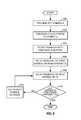
- FIG. 10a flow chart of an embodiment of a method for providing time-varying delay diversity is illustrated.
- Samples of a first symbol output by a modulatoris subject to a first phase shift ⁇ 1 , block 1000 .
- the samples of a second symbolare then subject to a phase shift ⁇ 2 , which is different than ⁇ 1 , block 1002 .
- a determinationis then made whether additional symbols have yet to be phase shifted, block 1004 . If not, then a phase shift which may be the same or different as ⁇ 1 or ⁇ 2 is then applied to the samples of a next symbol output by the modulator, block 106 . This process is then repeated, until there are no additional symbols to phase shift.
- the symbolsare subject to IFFT, block 1008 , the pre-pending of a cyclic prefix, block 1010 , and stores the symbol in memory, block 1012 , which in one embodiment may be a buffer.
- the samples for each modulated symbolare stored in memory according to the order in which they are provided after pre-pending of the cyclic prefix. In other embodiments, the samples of each modulated symbol may be stored in any order that is desired.
- the phase shiftmay be different between consecutive symbols, groups of symbols, or frames by a phase that is equal to a constant angle multiplied by a varying number corresponding to the location of the symbol in a symbol stream or other ordinal number.
- the constant anglemay be fixed or may vary according to other time constants. Also, the constant angle applied to symbols intended for different antennas may be different.
- the phase shiftmay vary according to a random phase with respect to any other symbols. This may be provided by utilizing a pseudo random code to generate the phase shift.
- FIG. 10illustrates waiting to perform IFFT and cyclic prefix pre-pending until a phase shift is applied to all of the symbols of a frame or burst period
- each symbolmay be subject to IFFT and cyclic prefix pre-pending either individually or in groups before completion of phase shifts to each of the symbols of a frame or burst period.
- transmitter 200 and 500may receive and process a respective modulation symbol stream (for MIMO without OFDM) or transmission symbol stream (for MIMO with OFDM) to generate a modulated signal, which is then transmitted from the associated antenna.
- a respective modulation symbol streamfor MIMO without OFDM
- transmission symbol streamfor MIMO with OFDM
- Other designs for the transmitter unitmay also be implemented and are within the scope of the invention.
- DSPdigital signal processor
- ASICapplication specific integrated circuit
- FPGAfield programmable gate array
- a general purpose processormay be a microprocessor, but in the alternative, the processor may be any conventional processor, processor, microprocessor, or state machine.
- a processormay also be implemented as a combination of devices, e.g., a combination of a DSP and a microprocessor, a plurality of microprocessors, one or more microprocessors in conjunction with a DSP core, multiple logic elements, multiple circuits, or any other such configuration.
- a software modulemay reside in RAM memory, flash memory, ROM memory, EPROM memory, EEPROM memory, registers, hard disk, a removable disk, a CD-ROM, or any other form of storage medium known in the art.
- An exemplary storage mediumis coupled to the processor such the processor can read information from, and write information to, the storage medium.
- the storage mediummay be integral to the processor.
- the processor and the storage mediummay reside in an ASIC.
- the ASICmay reside in a user terminal.
- the processor and the storage mediummay reside as discrete components in a user terminal.
Landscapes
- Engineering & Computer Science (AREA)
- Computer Networks & Wireless Communication (AREA)
- Signal Processing (AREA)
- Physics & Mathematics (AREA)
- Discrete Mathematics (AREA)
- General Physics & Mathematics (AREA)
- Mathematical Physics (AREA)
- Power Engineering (AREA)
- Radio Transmission System (AREA)
- Mobile Radio Communication Systems (AREA)
- Time-Division Multiplex Systems (AREA)
- Transmitters (AREA)
Abstract
Description
y=Hx+n, Eq (1)
- where y is the received vector, i.e., y=[y1y2. . . yN
R ]T, where {yi} is the entry received on the i-th received antenna and iε{1, . . . , NR}; - x is the transmitted vector, i.e., x=[x1x2. . . xN
T ]T, where {xj} is the entry transmitted from the j-th transmit antenna and jε{1, . . . , NT}; - H is the channel response matrix for the MIMO channel;
- n is the additive white Gaussian noise (AWGN) with a mean vector of 0 and a covariance matrix of Λn=σ2I, where 0 is a vector of zeros, I is the identity matrix with ones along the diagonal and zeros everywhere else, and σ2is the variance of the noise; and
- [.]Tdenotes the transpose of [.].
Due to scattering in the propagation environment, the NTsymbol streams transmitted from the NTtransmit antennas interfere with each other at the receiver. In particular, a given symbol stream transmitted from one transmit antenna may be received by all NRreceive antennas at different amplitudes and phases. Each received signal may then include a component of each of the NTtransmitted symbol streams. The NRreceived signals would collectively include all NTtransmitted symbols streams. However, these NTsymbol streams are dispersed among the NRreceived signals.
- where y is the received vector, i.e., y=[y1y2. . . yN
- spatial and space-time receiver processing techniques (which are also referred to as equalization techniques), and
- “successive nulling/equalization and interference cancellation” receiver processing technique (which is also referred to as “successive interference cancellation” or “successive cancellation” receiver processing technique).
The resulting overall channel in this case may be described as
where Hm(i,n) is the channel n-th discrete Fourier Transform (DFT) coefficient for the channel impulse response from the m-th transmitting antenna to the receiving antenna.
- U.S. patent application Ser. No. 09/993,087, entitled “Multiple-Access Multiple-Input Multiple-Output (MIMO) Communication System,” filed Nov. 6, 2001;
- U.S. patent application Ser. No. 09/854,235, entitled “Method and Apparatus for Processing Data in a Multiple-Input Multiple-Output (MIMO) Communication System Utilizing Channel State Information,” filed May 11, 2001;
- U.S. patent application Ser. Nos. 09/826,481 and 09/956,449, both entitled “Method and Apparatus for Utilizing Channel State Information in a Wireless Communication System,” respectively filed Mar. 23, 2001 and Sep. 18, 2001;
- U.S. patent application Ser. No. 09/776,075, entitled “Coding Scheme for a Wireless Communication System,” filed Feb. 1, 2001; and
- U.S. patent application Ser. No. 09/532,492, entitled “High Efficiency, High Performance Communications System Employing Multi-Carrier Modulation,” filed Mar. 30, 2000.
These applications are all assigned to the assignee of the present application and incorporated herein by reference. Application Ser. No. 09/776,075 describes a coding scheme whereby different rates may be achieved by coding the data with the same base code (e.g., a convolutional or Turbo code) and adjusting the puncturing to achieve the desired rate. Other coding and modulation schemes may also be used, and this is within the scope of the invention.
Claims (26)
Priority Applications (23)
| Application Number | Priority Date | Filing Date | Title |
|---|---|---|---|
| US11/078,176US8233555B2 (en) | 2004-05-17 | 2005-03-10 | Time varying delay diversity of OFDM |
| RU2006144849/09ARU2375823C2 (en) | 2004-05-17 | 2005-04-29 | Time-varying separation of periodic delay in ofdm system |
| CA2566487ACA2566487C (en) | 2004-05-17 | 2005-04-29 | Time varying cyclic delay diversity of ofdm |
| EP05744038AEP1757001B1 (en) | 2004-05-17 | 2005-04-29 | Time varying cyclic delay diversity of ofdm |
| AU2005330570AAU2005330570C1 (en) | 2004-05-17 | 2005-04-29 | Time varying cyclic diversity of OFDM |
| AT05744038TATE478487T1 (en) | 2004-05-17 | 2005-04-29 | TIME-VANGING CYCLIC DELAY DIVERSITY IN OFDM |
| MXPA06013443AMXPA06013443A (en) | 2004-05-17 | 2005-04-29 | Time varying cyclic delay diversity of ofdm. |
| BRPI0511170-6ABRPI0511170B1 (en) | 2004-05-17 | 2005-04-29 | METHOD AND APPARATUS FOR PROVIDING TRANSMISSION DIVERSITY IN A COMPUTER-READY MULTI-CHANNEL AND MEMORY COMMUNICATION SYSTEM |
| DE602005023012TDE602005023012D1 (en) | 2004-05-17 | 2005-04-29 | TIME-CHANGING CYCLIC DELAY DIVERSITY OF OFDM |
| KR1020067026233AKR100873837B1 (en) | 2004-05-17 | 2005-04-29 | ODFDM's time-varying cyclic delay diversity |
| JP2007527260AJP2007538466A (en) | 2004-05-17 | 2005-04-29 | OFDM time-varying periodic delay diversity |
| KR1020087018834AKR100909802B1 (en) | 2004-05-17 | 2005-04-29 | ODFDM's time-varying cyclic delay diversity |
| PCT/US2005/015041WO2005117321A1 (en) | 2004-05-17 | 2005-04-29 | Time varying cyclic delay diversity of ofdm |
| CN2005800241026ACN1989722B (en) | 2004-05-17 | 2005-04-29 | Time varying cyclic delay diversity of OFDM |
| MYPI20052163AMY142280A (en) | 2004-05-17 | 2005-05-13 | Time varying cyclic delay diversity of ofdm |
| TW101149146ATWI479834B (en) | 2004-05-17 | 2005-05-13 | Method of wireless transmission, wireless transmission apparatus, and computer-readable medium for time varying cyclic delay diversity of ofdm |
| TW094115667ATWI390885B (en) | 2004-05-17 | 2005-05-13 | Time varying cyclic delay diversity of ofdm |
| ARP050102005AAR049339A1 (en) | 2004-05-17 | 2005-05-16 | DIVERSITY OF VARIABLE CYCLE DELAY IN OFDM TIME (MULTIPLEX BY DIVISION OF ORTOGONAL FREQUENCY) |
| IL179181AIL179181A0 (en) | 2004-05-17 | 2006-11-09 | Time varying cyclic delay diversity of ofdm |
| JP2010166280AJP5221605B2 (en) | 2004-05-17 | 2010-07-23 | OFDM time-varying cyclic delay diversity |
| US13/550,549US9100076B2 (en) | 2004-05-17 | 2012-07-16 | Time varying delay diversity of OFDM |
| JP2012277645AJP5714559B2 (en) | 2004-05-17 | 2012-12-20 | OFDM time-varying cyclic delay diversity |
| JP2015006045AJP6215241B2 (en) | 2004-05-17 | 2015-01-15 | OFDM time-varying cyclic delay diversity |
Applications Claiming Priority (2)
| Application Number | Priority Date | Filing Date | Title |
|---|---|---|---|
| US57213704P | 2004-05-17 | 2004-05-17 | |
| US11/078,176US8233555B2 (en) | 2004-05-17 | 2005-03-10 | Time varying delay diversity of OFDM |
Related Child Applications (1)
| Application Number | Title | Priority Date | Filing Date |
|---|---|---|---|
| US13/550,549ContinuationUS9100076B2 (en) | 2004-05-17 | 2012-07-16 | Time varying delay diversity of OFDM |
Publications (2)
| Publication Number | Publication Date |
|---|---|
| US20050254592A1 US20050254592A1 (en) | 2005-11-17 |
| US8233555B2true US8233555B2 (en) | 2012-07-31 |
Family
ID=34968537
Family Applications (2)
| Application Number | Title | Priority Date | Filing Date |
|---|---|---|---|
| US11/078,176Active2027-08-05US8233555B2 (en) | 2004-05-17 | 2005-03-10 | Time varying delay diversity of OFDM |
| US13/550,549Expired - LifetimeUS9100076B2 (en) | 2004-05-17 | 2012-07-16 | Time varying delay diversity of OFDM |
Family Applications After (1)
| Application Number | Title | Priority Date | Filing Date |
|---|---|---|---|
| US13/550,549Expired - LifetimeUS9100076B2 (en) | 2004-05-17 | 2012-07-16 | Time varying delay diversity of OFDM |
Country Status (16)
| Country | Link |
|---|---|
| US (2) | US8233555B2 (en) |
| EP (1) | EP1757001B1 (en) |
| JP (4) | JP2007538466A (en) |
| KR (2) | KR100909802B1 (en) |
| AR (1) | AR049339A1 (en) |
| AT (1) | ATE478487T1 (en) |
| AU (1) | AU2005330570C1 (en) |
| BR (1) | BRPI0511170B1 (en) |
| CA (1) | CA2566487C (en) |
| DE (1) | DE602005023012D1 (en) |
| IL (1) | IL179181A0 (en) |
| MX (1) | MXPA06013443A (en) |
| MY (1) | MY142280A (en) |
| RU (1) | RU2375823C2 (en) |
| TW (2) | TWI479834B (en) |
| WO (1) | WO2005117321A1 (en) |
Cited By (9)
| Publication number | Priority date | Publication date | Assignee | Title |
|---|---|---|---|---|
| US20090010225A1 (en)* | 2007-03-21 | 2009-01-08 | Binita Gupta | Methods and Apparatus for RF Handoff in a Multi-Frequency Network |
| US8958408B1 (en)* | 2008-06-05 | 2015-02-17 | The Boeing Company | Coded aperture scanning |
| US9100076B2 (en) | 2004-05-17 | 2015-08-04 | Qualcomm Incorporated | Time varying delay diversity of OFDM |
| US10079633B2 (en)* | 2015-09-29 | 2018-09-18 | The United States Of America, As Represented By The Secretary Of The Army | Time-based and frequency-based radio beamforming waveform transmission |
| US10193612B2 (en)* | 2015-09-29 | 2019-01-29 | The United States Of America, As Represented By The Secretary Of The Army | Time-based radio beamforming waveform transmission |
| US10320467B2 (en) | 2015-09-29 | 2019-06-11 | The United States Of America, As Represented By The Secretary Of The Army | Frequency-based radio beamforming waveform transmission |
| US10439771B2 (en)* | 2012-05-22 | 2019-10-08 | Sun Patent Trust | Transmission method, reception method, transmitter, and receiver |
| US20200067746A1 (en)* | 2005-12-06 | 2020-02-27 | Microsoft Technology Licensing, Llc | Apparatus and method for transmitting data using a plurality of carriers |
| US11108453B2 (en)* | 2019-03-12 | 2021-08-31 | Intel Corporation | Antenna configuration parameters |
Families Citing this family (64)
| Publication number | Priority date | Publication date | Assignee | Title |
|---|---|---|---|---|
| US8149810B1 (en) | 2003-02-14 | 2012-04-03 | Marvell International Ltd. | Data rate adaptation in multiple-in-multiple-out systems |
| US7864678B1 (en) | 2003-08-12 | 2011-01-04 | Marvell International Ltd. | Rate adaptation in wireless systems |
| US7697449B1 (en)* | 2004-07-20 | 2010-04-13 | Marvell International Ltd. | Adaptively determining a data rate of packetized information transmission over a wireless channel |
| WO2006023559A2 (en)* | 2004-08-16 | 2006-03-02 | Wionics Research | Packet detection in time/frequency hopped wireless communication systems |
| US7436903B2 (en)* | 2004-09-29 | 2008-10-14 | Intel Corporation | Multicarrier transmitter and method for transmitting multiple data streams with cyclic delay diversity |
| JP4569929B2 (en)* | 2005-01-17 | 2010-10-27 | シャープ株式会社 | Communication device |
| US8335159B2 (en)* | 2005-04-21 | 2012-12-18 | Samsung Electronics Co., Ltd. | Method and system for introducing frequency selectivity into transmissions in an orthogonal frequency division multiplexing network |
| US8014463B2 (en)* | 2005-05-25 | 2011-09-06 | Qualcomm Incorporated | Delay diversity and spatial rotation systems and methods |
| US7660229B2 (en)* | 2005-06-20 | 2010-02-09 | Texas Instruments Incorporated | Pilot design and channel estimation |
| US7738356B2 (en)* | 2005-06-28 | 2010-06-15 | Broadcom Corporation | Multiple stream cyclic-shifted delay transmitter |
| EP1921774B1 (en)* | 2005-09-01 | 2016-07-20 | SnapTrack, Inc. | Wireless transmitting device and wireless transmitting method |
| US8165189B2 (en)* | 2005-10-07 | 2012-04-24 | University Of Washington Through Its Center For Commercialization | Dirty paper precoding with known interference structure at receiver |
| ES2367138T3 (en) | 2005-10-31 | 2011-10-28 | Sharp Kabushiki Kaisha | WIRELESS TRANSMITTER. |
| WO2007052649A1 (en) | 2005-10-31 | 2007-05-10 | Sharp Kabushiki Kaisha | Radio transmitter, radio communication system, and radio transmission method |
| GB2433397B (en)* | 2005-12-16 | 2008-09-10 | Toshiba Res Europ Ltd | A configurable block cdma scheme |
| CN102594422B (en) | 2005-12-20 | 2014-12-03 | 华为技术有限公司 | sending control method, base station and mobile radio station |
| JP4658146B2 (en) | 2005-12-26 | 2011-03-23 | シャープ株式会社 | Wireless transmitter and wireless transmission method |
| JP4425880B2 (en)* | 2006-01-18 | 2010-03-03 | 株式会社エヌ・ティ・ティ・ドコモ | Communication apparatus, mobile station and method |
| JP4727545B2 (en)* | 2006-02-07 | 2011-07-20 | シャープ株式会社 | Wireless transmitter, wireless transmission method, wireless communication system, program thereof, and IFFT arithmetic circuit |
| US20070189151A1 (en)* | 2006-02-10 | 2007-08-16 | Interdigital Technology Corporation | Method and apparatus for performing uplink transmission in a multiple-input multiple-output single carrier frequency division multiple access system |
| TW200735560A (en)* | 2006-02-10 | 2007-09-16 | Interdigital Tech Corp | Method and apparatus for performing uplink transmission in a multiple-input multiple-output single carrier frequency division multiple access system |
| KR101260835B1 (en)* | 2006-02-28 | 2013-05-06 | 삼성전자주식회사 | Apparatus and method for transceiving a signal in a multi antenna system |
| KR100889748B1 (en) | 2006-03-24 | 2009-03-24 | 한국전자통신연구원 | Apparatus and Method of Inter-Cell macro-diversity for providing Broadcast/Multicast Service using multi-antenna |
| KR101241895B1 (en)* | 2006-04-10 | 2013-03-11 | 엘지전자 주식회사 | method for repetitive transmission using a plurality of carrier |
| CN101056132B (en)* | 2006-04-13 | 2011-04-20 | 上海贝尔阿尔卡特股份有限公司 | Method and device for processing the base band of the space-time/space frequency/space diversity transmitter |
| TWI343200B (en)* | 2006-05-26 | 2011-06-01 | Lg Electronics Inc | Method and apparatus for signal generation using phase-shift based pre-coding |
| US20100020737A1 (en)* | 2006-07-25 | 2010-01-28 | Hidenobu Fukumasa | Mobile communication system, base station apparatus and mobile station device |
| US7804910B2 (en)* | 2006-08-08 | 2010-09-28 | Adaptix, Inc. | Systems and methods for wireless communication system channel allocation using international delay distortion |
| US20080101482A1 (en)* | 2006-10-26 | 2008-05-01 | General Instrument Corporation | Method and apparatus for refining MIMO channel estimation using the signal field of the data frame |
| KR100939738B1 (en)* | 2006-12-21 | 2010-01-29 | 삼성전자주식회사 | Cyclic delay diversity apparatus and method in multi-antenna wireless communication system |
| US8780771B2 (en) | 2007-02-06 | 2014-07-15 | Qualcomm Incorporated | Cyclic delay diversity and precoding for wireless communication |
| WO2008098093A2 (en)* | 2007-02-06 | 2008-08-14 | Qualcomm Incorporated | Apparatus and method for mimo transmission with explicit and implicit cyclic delays |
| US8509710B2 (en) | 2007-02-06 | 2013-08-13 | Qualcomm Incorporated | MIMO transmission with explicit and implicit cyclic delays |
| US8750248B2 (en) | 2007-03-21 | 2014-06-10 | Qualcomm Incorporated | Methods and apparatus for RF handoff in a multi-frequency network |
| US8457064B2 (en) | 2007-03-21 | 2013-06-04 | Qualcomm Incorporated | Methods and apparatus for RF handoff in a multi-frequency network |
| US8948757B2 (en) | 2007-03-21 | 2015-02-03 | Qualcomm Incorporated | Methods and apparatus for RF handoff in a multi-frequency network |
| US8737353B2 (en) | 2007-03-21 | 2014-05-27 | Qualcomm Incorporated | Methods and apparatus for RF handoff in a multi-frequency network |
| US20100190486A1 (en)* | 2007-05-31 | 2010-07-29 | Panasonic Corporation | Radio communication mobile station device and cdd mode judging method |
| US8160177B2 (en) | 2007-06-25 | 2012-04-17 | Samsung Electronics Co., Ltd. | Transmit methods with delay diversity and space-frequency diversity |
| KR20090030200A (en) | 2007-09-19 | 2009-03-24 | 엘지전자 주식회사 | Data Transceiving Method Using Phase-Transition-Based Precoding and Transceivers Supporting It |
| KR101413309B1 (en)* | 2007-10-08 | 2014-06-27 | 엘지전자 주식회사 | Transmitter and data transmission method for reducing channel selectivity |
| KR100901760B1 (en) | 2007-11-08 | 2009-06-11 | 한국전자통신연구원 | Cyclic Delay Diversity Method with an Optimal Cyclic Delay Value and Its Transmitter |
| KR101048437B1 (en)* | 2007-11-30 | 2011-07-11 | 삼성전자주식회사 | Method and apparatus for time varying cyclic delay diversity in wireless communication system |
| US8570939B2 (en) | 2008-03-07 | 2013-10-29 | Qualcomm Incorporated | Methods and systems for choosing cyclic delays in multiple antenna OFDM systems |
| EP2266247A2 (en)* | 2008-03-14 | 2010-12-29 | QUALCOMM Incorporated | Methods and systems for choosing cyclic delays in multiple antenna ofdm systems |
| US8391132B2 (en)* | 2008-03-31 | 2013-03-05 | Sirius Xm Radio Inc. | Slow speed mute resistance via selective COFDM bin loading |
| JP5226122B2 (en)* | 2008-05-05 | 2013-07-03 | エルジー エレクトロニクス インコーポレイティド | Cyclic delay diversity based forwarding with delay hopping |
| KR101497928B1 (en)* | 2008-09-25 | 2015-03-03 | 삼성전자주식회사 | Apparatus for transmitting and receiving signal in multi-input multi-output system, and mehtod the same |
| JP4465020B2 (en)* | 2008-09-26 | 2010-05-19 | 株式会社エヌ・ティ・ティ・ドコモ | Mobile station and radio base station |
| EP2375580B1 (en)* | 2010-03-29 | 2016-10-12 | Sequans Communications | Method and apparatus for optimizing transmission diversity |
| US8737506B1 (en)* | 2010-12-29 | 2014-05-27 | Sprint Communications Company L.P. | Determination of transmit diversity transmission delays |
| US9131460B2 (en)* | 2011-02-15 | 2015-09-08 | Intel Mobile Communications GmbH | Radio relay communication device, method for relaying data, mobile terminal, and method for determining a sender of a signal |
| KR20200085931A (en) | 2011-02-18 | 2020-07-15 | 선 페이턴트 트러스트 | Method of signal generation and signal generating device |
| US8861638B2 (en)* | 2011-09-26 | 2014-10-14 | Cambridge Silicon Radio Limited | Transmitter with reduced peak-to-mean amplitude ratio |
| US9450659B2 (en)* | 2011-11-04 | 2016-09-20 | Alcatel Lucent | Method and apparatus to generate virtual sector wide static beams using phase shift transmit diversity |
| US9692123B2 (en)* | 2012-09-17 | 2017-06-27 | Qualcomm Incorporated | Systems and methods of controlling antenna radiation patterns |
| US9602228B1 (en)* | 2013-01-18 | 2017-03-21 | Gregory R. Warnes | Method and apparatus for transmission and reception of a signal over multiple frequencies with time offset encoding at each frequency |
| US9401823B2 (en) | 2013-11-26 | 2016-07-26 | Plusn Llc | System and method for radio frequency carrier aggregation |
| US9647861B1 (en)* | 2014-01-30 | 2017-05-09 | Rockwell Collins, Inc. | Multiple antenna transmission of pulsed data communication messages with phase or time dithering for reduction of static interference nulls |
| WO2016167614A1 (en)* | 2015-04-16 | 2016-10-20 | 엘지전자 주식회사 | Symbol-mapping method and radio device for decreasing papr |
| US20170171721A1 (en)* | 2015-12-10 | 2017-06-15 | Linear Dms Solutions Sdn. Bhd. | Bluetooth protocol broadcasting system |
| EP3481142B1 (en)* | 2016-08-08 | 2020-10-28 | Huawei Technologies Co., Ltd. | Data transmission method and transmitting terminal device |
| EP3602812A1 (en)* | 2017-03-24 | 2020-02-05 | Telefonaktiebolaget LM Ericsson (PUBL) | Methods for multi-antenna transmission in vehicular communications |
| US10601517B1 (en)* | 2019-01-22 | 2020-03-24 | Fujitsu Limited | Probabilistic shaping on eight-dimensional super-symbols |
Citations (26)
| Publication number | Priority date | Publication date | Assignee | Title |
|---|---|---|---|---|
| US4513412A (en) | 1983-04-25 | 1985-04-23 | At&T Bell Laboratories | Time division adaptive retransmission technique for portable radio telephones |
| JPH06169273A (en) | 1991-09-07 | 1994-06-14 | Motorola Ltd | Radio receiver, transmitter and repeater for execution of diversity |
| JPH08265244A (en) | 1995-03-20 | 1996-10-11 | Nippon Telegr & Teleph Corp <Ntt> | Base station device for spread spectrum communication |
| EP1065855A1 (en) | 1999-06-29 | 2001-01-03 | Sony International (Europe) GmbH | Adaptation of cyclic extensions in an OFDM communication system |
| EP1073214A1 (en) | 1999-02-16 | 2001-01-31 | Mitsubishi Denki Kabushiki Kaisha | Radio communication system, transmitter and receiver |
| JP2001102976A (en) | 1999-08-24 | 2001-04-13 | Samsung Electronics Co Ltd | Closed loop transmission antenna diversity method in next generation mobile communication system, base station apparatus using the method, and mobile station apparatus |
| WO2002001732A2 (en) | 2000-06-02 | 2002-01-03 | Nokia Corporation | Closed loop feedback system for improved down link performance |
| US6377632B1 (en)* | 2000-01-24 | 2002-04-23 | Iospan Wireless, Inc. | Wireless communication system and method using stochastic space-time/frequency division multiplexing |
| WO2002045293A2 (en) | 2000-12-02 | 2002-06-06 | Koninklijke Philips Electronics N.V. | Radio communicati0n system |
| US20020122381A1 (en)* | 2000-09-01 | 2002-09-05 | Shiquan Wu | Channels estimation for multiple input - multiple output, orthogonal frequency division multiplexing (OFDM) system |
| US20020154705A1 (en) | 2000-03-22 | 2002-10-24 | Walton Jay R. | High efficiency high performance communications system employing multi-carrier modulation |
| US20030137926A1 (en)* | 2001-11-10 | 2003-07-24 | Samsung Electronics Co., Ltd. | STFBC coding/decoding apparatus and method in an OFDM mobile communication system |
| WO2004002010A1 (en) | 2002-06-20 | 2003-12-31 | Lg Electronics Inc. | Improved mimo system and method for radio communication |
| JP2004064654A (en) | 2002-07-31 | 2004-02-26 | Matsushita Electric Ind Co Ltd | Multicarrier transmission apparatus and multicarrier transmission method |
| KR20040028111A (en) | 2002-09-28 | 2004-04-03 | 주식회사 케이티 | DSP apparatus and method in OFDM receiver using antenna diversity technique |
| US6771706B2 (en) | 2001-03-23 | 2004-08-03 | Qualcomm Incorporated | Method and apparatus for utilizing channel state information in a wireless communication system |
| US6785341B2 (en) | 2001-05-11 | 2004-08-31 | Qualcomm Incorporated | Method and apparatus for processing data in a multiple-input multiple-output (MIMO) communication system utilizing channel state information |
| US6842487B1 (en)* | 2000-09-22 | 2005-01-11 | Telefonaktiebolaget Lm Ericsson (Publ) | Cyclic delay diversity for mitigating intersymbol interference in OFDM systems |
| US20050105631A1 (en)* | 2003-10-01 | 2005-05-19 | Giannakis Georgios B. | Full-diversity, full-rate complex-field space-time coding for wireless communication |
| US6961388B2 (en) | 2001-02-01 | 2005-11-01 | Qualcomm, Incorporated | Coding scheme for a wireless communication system |
| US20060221898A1 (en)* | 2003-04-16 | 2006-10-05 | Martin Bossert | Method and transmitter for transmitting data in a multi-carrier system via a number of transmitting antennas |
| EP1757001A1 (en) | 2004-05-17 | 2007-02-28 | Qualcomm, Incorporated | Time varying cyclic delay diversity of ofdm |
| US20090141620A1 (en)* | 2007-11-30 | 2009-06-04 | Samsung Electronics Co. Ltd. | Apparatus and method for time-varying cyclic delay diversity in a wireless communication system |
| US20100022193A1 (en)* | 2005-10-27 | 2010-01-28 | Bruno Melis | Method and System for Multiple Antenna Communications Using Multiple Transmission Modes, Related Apparatus and Computer Program Product |
| US20100322349A1 (en)* | 2006-10-23 | 2010-12-23 | Moon Il Lee | Method for transmitting data using cyclic delay diversity |
| US20110001579A1 (en)* | 2007-11-28 | 2011-01-06 | Vincenzo Boffa | Tunable ridge waveguide delay line |
Family Cites Families (21)
| Publication number | Priority date | Publication date | Assignee | Title |
|---|---|---|---|---|
| JP2558660B2 (en)* | 1986-12-03 | 1996-11-27 | 松下電器産業株式会社 | Data transmission device |
| JP2572765B2 (en)* | 1987-05-19 | 1997-01-16 | 日本電信電話株式会社 | Transmission path diversity transmission method |
| JPH05167480A (en)* | 1991-12-12 | 1993-07-02 | Nec Corp | Transmitter in multiple address communication system |
| US5574989A (en)* | 1993-04-26 | 1996-11-12 | Hughes Electronics | Time division multiple access cellular communication system and method employing base station diversity transmission |
| FI961944L (en)* | 1994-09-09 | 1996-05-08 | Motorola Inc | Radio antenna arrangement |
| JP2705623B2 (en)* | 1995-03-22 | 1998-01-28 | 日本電気株式会社 | Diversity transmission / reception method and transceiver |
| JP3338747B2 (en)* | 1995-12-28 | 2002-10-28 | 日本電気株式会社 | Interference wave canceller |
| EP2280494A3 (en)* | 1996-04-26 | 2011-12-07 | AT & T Corp. | Method and apparatus for data transmission using multiple transmit antennas |
| US6175550B1 (en)* | 1997-04-01 | 2001-01-16 | Lucent Technologies, Inc. | Orthogonal frequency division multiplexing system with dynamically scalable operating parameters and method thereof |
| JP3097623B2 (en)* | 1997-10-21 | 2000-10-10 | 日本電気株式会社 | Diversity transmission / reception system |
| US6795508B1 (en)* | 1997-12-02 | 2004-09-21 | Qualcomm, Incorporated | Method and apparatus for obtaining transmit diversity using switched antennas |
| US6327299B1 (en)* | 1999-08-31 | 2001-12-04 | Motorola, Inc. | Method and system for measuring and adjusting the quality of an orthogonal transmit diversity signal in a wireless communications system |
| US20030026348A1 (en)* | 2001-06-07 | 2003-02-06 | National University Of Singapore | Wireless communication apparatus and method |
| JP2002374193A (en)* | 2001-06-13 | 2002-12-26 | Nec Saitama Ltd | Transmission diversity delay correction system |
| JP4731055B2 (en)* | 2001-06-29 | 2011-07-20 | パナソニック株式会社 | Wireless communication apparatus and wireless communication method |
| US20030125040A1 (en) | 2001-11-06 | 2003-07-03 | Walton Jay R. | Multiple-access multiple-input multiple-output (MIMO) communication system |
| JP2004297142A (en)* | 2003-03-25 | 2004-10-21 | Nippon Hoso Kyokai <Nhk> | Diversity transmitter, diversity receiver, and diversity transmission system |
| AU2003271665A1 (en)* | 2003-09-30 | 2005-05-11 | Docomo Communications Laboratories Europe Gmbh | Apparatus and method for cyclic delay diversity |
| JP4413232B2 (en)* | 2004-02-19 | 2010-02-10 | 株式会社エヌ・ティ・ティ・ドコモ | Channel evaluator and method for evaluating channel transfer function, and apparatus and method for supplying pilot sequence |
| DE602004014984D1 (en)* | 2004-02-19 | 2008-08-21 | Ntt Docomo Inc | DEVICE AND METHOD FOR ESTIMATING AN EFFECTIVE CHANNEL AND DEVICE AND METHOD FOR PROVIDING PILOT SEQUENCES |
| US8285226B2 (en)* | 2004-05-07 | 2012-10-09 | Qualcomm Incorporated | Steering diversity for an OFDM-based multi-antenna communication system |
- 2005
- 2005-03-10USUS11/078,176patent/US8233555B2/enactiveActive
- 2005-04-29BRBRPI0511170-6Apatent/BRPI0511170B1/enactiveIP Right Grant
- 2005-04-29KRKR1020087018834Apatent/KR100909802B1/ennot_activeExpired - Lifetime
- 2005-04-29WOPCT/US2005/015041patent/WO2005117321A1/enactiveApplication Filing
- 2005-04-29EPEP05744038Apatent/EP1757001B1/ennot_activeExpired - Lifetime
- 2005-04-29JPJP2007527260Apatent/JP2007538466A/ennot_activeWithdrawn
- 2005-04-29DEDE602005023012Tpatent/DE602005023012D1/ennot_activeExpired - Lifetime
- 2005-04-29CACA2566487Apatent/CA2566487C/ennot_activeExpired - Lifetime
- 2005-04-29RURU2006144849/09Apatent/RU2375823C2/enactive
- 2005-04-29ATAT05744038Tpatent/ATE478487T1/ennot_activeIP Right Cessation
- 2005-04-29AUAU2005330570Apatent/AU2005330570C1/ennot_activeCeased
- 2005-04-29MXMXPA06013443Apatent/MXPA06013443A/enactiveIP Right Grant
- 2005-04-29KRKR1020067026233Apatent/KR100873837B1/ennot_activeExpired - Lifetime
- 2005-05-13TWTW101149146Apatent/TWI479834B/enactive
- 2005-05-13MYMYPI20052163Apatent/MY142280A/enunknown
- 2005-05-13TWTW094115667Apatent/TWI390885B/ennot_activeIP Right Cessation
- 2005-05-16ARARP050102005Apatent/AR049339A1/enunknown
- 2006
- 2006-11-09ILIL179181Apatent/IL179181A0/enunknown
- 2010
- 2010-07-23JPJP2010166280Apatent/JP5221605B2/ennot_activeExpired - Lifetime
- 2012
- 2012-07-16USUS13/550,549patent/US9100076B2/ennot_activeExpired - Lifetime
- 2012-12-20JPJP2012277645Apatent/JP5714559B2/ennot_activeExpired - Lifetime
- 2015
- 2015-01-15JPJP2015006045Apatent/JP6215241B2/ennot_activeExpired - Lifetime
Patent Citations (28)
| Publication number | Priority date | Publication date | Assignee | Title |
|---|---|---|---|---|
| US4513412A (en) | 1983-04-25 | 1985-04-23 | At&T Bell Laboratories | Time division adaptive retransmission technique for portable radio telephones |
| JPH06169273A (en) | 1991-09-07 | 1994-06-14 | Motorola Ltd | Radio receiver, transmitter and repeater for execution of diversity |
| JPH08265244A (en) | 1995-03-20 | 1996-10-11 | Nippon Telegr & Teleph Corp <Ntt> | Base station device for spread spectrum communication |
| EP1073214A1 (en) | 1999-02-16 | 2001-01-31 | Mitsubishi Denki Kabushiki Kaisha | Radio communication system, transmitter and receiver |
| EP1065855A1 (en) | 1999-06-29 | 2001-01-03 | Sony International (Europe) GmbH | Adaptation of cyclic extensions in an OFDM communication system |
| JP2001102976A (en) | 1999-08-24 | 2001-04-13 | Samsung Electronics Co Ltd | Closed loop transmission antenna diversity method in next generation mobile communication system, base station apparatus using the method, and mobile station apparatus |
| US6377632B1 (en)* | 2000-01-24 | 2002-04-23 | Iospan Wireless, Inc. | Wireless communication system and method using stochastic space-time/frequency division multiplexing |
| US20020154705A1 (en) | 2000-03-22 | 2002-10-24 | Walton Jay R. | High efficiency high performance communications system employing multi-carrier modulation |
| WO2002001732A2 (en) | 2000-06-02 | 2002-01-03 | Nokia Corporation | Closed loop feedback system for improved down link performance |
| JP2004502376A (en) | 2000-06-02 | 2004-01-22 | ノキア コーポレーション | Closed loop feedback system to improve down link performance |
| US20020122381A1 (en)* | 2000-09-01 | 2002-09-05 | Shiquan Wu | Channels estimation for multiple input - multiple output, orthogonal frequency division multiplexing (OFDM) system |
| US6842487B1 (en)* | 2000-09-22 | 2005-01-11 | Telefonaktiebolaget Lm Ericsson (Publ) | Cyclic delay diversity for mitigating intersymbol interference in OFDM systems |
| WO2002045293A2 (en) | 2000-12-02 | 2002-06-06 | Koninklijke Philips Electronics N.V. | Radio communicati0n system |
| US6961388B2 (en) | 2001-02-01 | 2005-11-01 | Qualcomm, Incorporated | Coding scheme for a wireless communication system |
| US7006848B2 (en) | 2001-03-23 | 2006-02-28 | Qualcomm Incorporated | Method and apparatus for utilizing channel state information in a wireless communication system |
| US6771706B2 (en) | 2001-03-23 | 2004-08-03 | Qualcomm Incorporated | Method and apparatus for utilizing channel state information in a wireless communication system |
| US6785341B2 (en) | 2001-05-11 | 2004-08-31 | Qualcomm Incorporated | Method and apparatus for processing data in a multiple-input multiple-output (MIMO) communication system utilizing channel state information |
| US20030137926A1 (en)* | 2001-11-10 | 2003-07-24 | Samsung Electronics Co., Ltd. | STFBC coding/decoding apparatus and method in an OFDM mobile communication system |
| WO2004002010A1 (en) | 2002-06-20 | 2003-12-31 | Lg Electronics Inc. | Improved mimo system and method for radio communication |
| JP2004064654A (en) | 2002-07-31 | 2004-02-26 | Matsushita Electric Ind Co Ltd | Multicarrier transmission apparatus and multicarrier transmission method |
| KR20040028111A (en) | 2002-09-28 | 2004-04-03 | 주식회사 케이티 | DSP apparatus and method in OFDM receiver using antenna diversity technique |
| US20060221898A1 (en)* | 2003-04-16 | 2006-10-05 | Martin Bossert | Method and transmitter for transmitting data in a multi-carrier system via a number of transmitting antennas |
| US20050105631A1 (en)* | 2003-10-01 | 2005-05-19 | Giannakis Georgios B. | Full-diversity, full-rate complex-field space-time coding for wireless communication |
| EP1757001A1 (en) | 2004-05-17 | 2007-02-28 | Qualcomm, Incorporated | Time varying cyclic delay diversity of ofdm |
| US20100022193A1 (en)* | 2005-10-27 | 2010-01-28 | Bruno Melis | Method and System for Multiple Antenna Communications Using Multiple Transmission Modes, Related Apparatus and Computer Program Product |
| US20100322349A1 (en)* | 2006-10-23 | 2010-12-23 | Moon Il Lee | Method for transmitting data using cyclic delay diversity |
| US20110001579A1 (en)* | 2007-11-28 | 2011-01-06 | Vincenzo Boffa | Tunable ridge waveguide delay line |
| US20090141620A1 (en)* | 2007-11-30 | 2009-06-04 | Samsung Electronics Co. Ltd. | Apparatus and method for time-varying cyclic delay diversity in a wireless communication system |
Non-Patent Citations (17)
| Title |
|---|
| "Discrete Message Transmission," ed. by V.P. Shuvalov, Moscow, Radio and Communication, 1990, pp. 44-45. |
| "Radio Transmitters," ed. by Blagoveshenskiy, M.V., and Utkin, G.M., Moscow, Radio and Communication, 1982, pp. 336-339. |
| Armin Dammann and Stefan Kaiser, "Transmit/Receive-Antenna Diversity Techniques for OFDM Systems", German Aerospace Center, vol. 13, No. 5 Sep.-Oct. 2002.* |
| Bauch et al "Orthogonal Frequency Division Miltiple Access with Cyclic Delay Diversity" IEEE (2004). |
| Dammann, A. et al., "Beamforming in Combination with Space-Time Diversity for Broadband OFDM Systems", ICC 2002. 2002 IEEE International Conference on Communications. Apr. 28-May 2, 2002, pp. 165-171, XP010589479. |
| Dammann, A., Kaiser, S.,"Standard conformable antenna diversity techniques for OFDM and its application to the DVB-T system", German Aerospace Center, 2001 IEEE.* |
| Dammann, et al., "Standard Conformable Antenna Diversity Techniques for OFDM and its Application to the DVB-T System," GLOBECOM '01, IEEE Global Telecommunications Conference, 2001, vol. 5, Nov. 25-29, 2001, pp. 3100-3105. |
| Hiroike, A., Adachi, F., Nakajima, N., "Combined effects of phase sweeping transmitter diversity and channel coding", NTT Radio Communication Systems Laboratories, Kanagawa, Japan, 1992 IEEE.* |
| International Preliminary Report on Patentability-PCT/US05/015041, The International Bureau of WIPO-Geneva, Switzerland, Nov. 21, 2006. |
| International Search Report-PCT/US05/015041, International Search Authority-European Patent Office, Aug. 22, 2005. |
| Kaiser, "Spatial transmit diversity techniques for broadband OFDM systems", German aerospace center publisher, 2000 IEEE Global Telecommunications Conference, GLOBECOM, vol. 3, pp. 1824-1828. |
| R1-062302, Time varying CDD/CSD, Siemens, 3GPP TSG RAN WG1 LTE, Tallinn, Estonia, Aug. 28 to Sep. 1, 2006.* |
| Simon Plass, Armin Dammann, Gerd Richter and Martin Bossert, Resulting Channel Characteristics from Time-Varying Cyclic Delay Diversity in OFDM, German Aerospace Center (DLR) and Ulm University, Germany, IEEE 2007.* |
| Spilker, "Digital Satellite Communications," Moscow, Publishing House "Communication," 1979, p. 278, 242. |
| Stefan Kaiser, "Spatial Transmit Diversity Techniques for Broadband OFDM Systems", German Aerospace Center, 2000 IEEE.* |
| Viswanath, et al., "Opportunistic Beamforming Using Dumb Antennas," IEEE Transactions on Information Theory, vol. 48, Issue 6, Jun. 2002, pp. 1277-1294. |
| Written Opinion-PCT/US05/015041, International Searching Authority-European Patent Office, Aug. 22, 2005. |
Cited By (16)
| Publication number | Priority date | Publication date | Assignee | Title |
|---|---|---|---|---|
| US9100076B2 (en) | 2004-05-17 | 2015-08-04 | Qualcomm Incorporated | Time varying delay diversity of OFDM |
| US20200067746A1 (en)* | 2005-12-06 | 2020-02-27 | Microsoft Technology Licensing, Llc | Apparatus and method for transmitting data using a plurality of carriers |
| US10992505B2 (en)* | 2005-12-06 | 2021-04-27 | Microsoft Technology Licensing, Llc | Apparatus and method for transmitting data using a plurality of carriers |
| US8737350B2 (en) | 2007-03-21 | 2014-05-27 | Qualcomm Incorporated | Methods and apparatus for RF handoff in a multi-frequency network |
| US20090010225A1 (en)* | 2007-03-21 | 2009-01-08 | Binita Gupta | Methods and Apparatus for RF Handoff in a Multi-Frequency Network |
| US8958408B1 (en)* | 2008-06-05 | 2015-02-17 | The Boeing Company | Coded aperture scanning |
| US11683133B2 (en) | 2012-05-22 | 2023-06-20 | Sun Patent Trust | Transmission method, reception method, transmitter, and receiver |
| US12184565B2 (en)* | 2012-05-22 | 2024-12-31 | Sun Patent Trust | Transmission method, reception method, transmitter, and receiver |
| US20230275712A1 (en)* | 2012-05-22 | 2023-08-31 | Sun Patent Trust | Transmission method, reception method, transmitter, and receiver |
| US10439771B2 (en)* | 2012-05-22 | 2019-10-08 | Sun Patent Trust | Transmission method, reception method, transmitter, and receiver |
| US10693608B2 (en) | 2012-05-22 | 2020-06-23 | Sun Patent Trust | Transmission method, reception method, transmitter, and receiver |
| US11025380B2 (en) | 2012-05-22 | 2021-06-01 | Sun Patent Trust | Transmission method, reception method, transmitter, and receiver |
| US10079633B2 (en)* | 2015-09-29 | 2018-09-18 | The United States Of America, As Represented By The Secretary Of The Army | Time-based and frequency-based radio beamforming waveform transmission |
| US10320467B2 (en) | 2015-09-29 | 2019-06-11 | The United States Of America, As Represented By The Secretary Of The Army | Frequency-based radio beamforming waveform transmission |
| US10193612B2 (en)* | 2015-09-29 | 2019-01-29 | The United States Of America, As Represented By The Secretary Of The Army | Time-based radio beamforming waveform transmission |
| US11108453B2 (en)* | 2019-03-12 | 2021-08-31 | Intel Corporation | Antenna configuration parameters |
Also Published As
Similar Documents
| Publication | Publication Date | Title |
|---|---|---|
| US8233555B2 (en) | Time varying delay diversity of OFDM | |
| KR100906285B1 (en) | Space?time block coding in orthogonal frequency division communication systems | |
| US7974359B2 (en) | Methods and apparatus for mitigating multi-antenna correlation effect in communication systems | |
| US20040121730A1 (en) | Transmission scheme for multi-carrier MIMO systems | |
| KR20110060225A (en) | How to determine adaptive modulation and coding scheme in multi-antenna system | |
| US20050152267A1 (en) | Apparatus and method for canceling interference signal in an orthogonal frequency division multiplexing system using multiple antennas | |
| CN1989722B (en) | Time varying cyclic delay diversity of OFDM | |
| Bauch | Multistream differential modulation for cyclic delay diversity in OFDM | |
| HK1105728A (en) | Time varying cyclic delay diversity of ofdm | |
| Deshmukh et al. | INTERNATIONAL JOURNAL OF ELECTRONICS AND COMMUNICATION ENGINEERING & TECHNOLOGY (IJECET) |
Legal Events
| Date | Code | Title | Description |
|---|---|---|---|
| AS | Assignment | Owner name:QUALCOMM INCORPORATED, CALIFORNIA Free format text:ASSIGNMENT OF ASSIGNORS INTEREST;ASSIGNORS:NAGUIB, AYMAN FAWAY;AGRAWAL, AVNEESH;SIGNING DATES FROM 20050309 TO 20050311;REEL/FRAME:016683/0772 Owner name:QUALCOMM INCORPORATED, CALIFORNIA Free format text:ASSIGNMENT OF ASSIGNORS INTEREST;ASSIGNORS:NAGUIB, AYMAN FAWAY;AGRAWAL, AVNEESH;REEL/FRAME:016683/0772;SIGNING DATES FROM 20050309 TO 20050311 | |
| AS | Assignment | Owner name:QUALCOMM INCORPORATED, CALIFORNIA Free format text:ASSIGNMENT OF ASSIGNORS INTEREST;ASSIGNORS:NAGUIB, AYMAN FAWZY;AGRAWAL, AVNEESH;SIGNING DATES FROM 20050309 TO 20050311;REEL/FRAME:017211/0863 Owner name:QUALCOMM INCORPORATED, CALIFORNIA Free format text:ASSIGNMENT OF ASSIGNORS INTEREST;ASSIGNORS:NAGUIB, AYMAN FAWZY;AGRAWAL, AVNEESH;REEL/FRAME:017211/0863;SIGNING DATES FROM 20050309 TO 20050311 | |
| AS | Assignment | Owner name:QUALCOMM INCORPORATED, CALIFORNIA Free format text:ASSIGNMENT OF ASSIGNORS INTEREST;ASSIGNORS:NAGUIB, AYMAN FAWZY;AGRAWAL, AVNEESH;SIGNING DATES FROM 20070416 TO 20070419;REEL/FRAME:019202/0656 Owner name:QUALCOMM INCORPORATED, CALIFORNIA Free format text:ASSIGNMENT OF ASSIGNORS INTEREST;ASSIGNORS:NAGUIB, AYMAN FAWZY;AGRAWAL, AVNEESH;REEL/FRAME:019202/0656;SIGNING DATES FROM 20070416 TO 20070419 | |
| STCF | Information on status: patent grant | Free format text:PATENTED CASE | |
| FPAY | Fee payment | Year of fee payment:4 | |
| MAFP | Maintenance fee payment | Free format text:PAYMENT OF MAINTENANCE FEE, 8TH YEAR, LARGE ENTITY (ORIGINAL EVENT CODE: M1552); ENTITY STATUS OF PATENT OWNER: LARGE ENTITY Year of fee payment:8 | |
| MAFP | Maintenance fee payment | Free format text:PAYMENT OF MAINTENANCE FEE, 12TH YEAR, LARGE ENTITY (ORIGINAL EVENT CODE: M1553); ENTITY STATUS OF PATENT OWNER: LARGE ENTITY Year of fee payment:12 |