US8233206B2 - User interaction with holographic images - Google Patents
User interaction with holographic imagesDownload PDFInfo
- Publication number
- US8233206B2 US8233206B2US12/050,527US5052708AUS8233206B2US 8233206 B2US8233206 B2US 8233206B2US 5052708 AUS5052708 AUS 5052708AUS 8233206 B2US8233206 B2US 8233206B2
- Authority
- US
- United States
- Prior art keywords
- image
- input device
- feature
- response
- user
- Prior art date
- Legal status (The legal status is an assumption and is not a legal conclusion. Google has not performed a legal analysis and makes no representation as to the accuracy of the status listed.)
- Expired - Fee Related, expires
Links
Images


Classifications
- G—PHYSICS
- G03—PHOTOGRAPHY; CINEMATOGRAPHY; ANALOGOUS TECHNIQUES USING WAVES OTHER THAN OPTICAL WAVES; ELECTROGRAPHY; HOLOGRAPHY
- G03H—HOLOGRAPHIC PROCESSES OR APPARATUS
- G03H1/00—Holographic processes or apparatus using light, infrared or ultraviolet waves for obtaining holograms or for obtaining an image from them; Details peculiar thereto
- G03H1/0005—Adaptation of holography to specific applications
- G—PHYSICS
- G06—COMPUTING OR CALCULATING; COUNTING
- G06F—ELECTRIC DIGITAL DATA PROCESSING
- G06F3/00—Input arrangements for transferring data to be processed into a form capable of being handled by the computer; Output arrangements for transferring data from processing unit to output unit, e.g. interface arrangements
- G06F3/01—Input arrangements or combined input and output arrangements for interaction between user and computer
- G06F3/011—Arrangements for interaction with the human body, e.g. for user immersion in virtual reality
- G06F3/014—Hand-worn input/output arrangements, e.g. data gloves
- G—PHYSICS
- G06—COMPUTING OR CALCULATING; COUNTING
- G06F—ELECTRIC DIGITAL DATA PROCESSING
- G06F3/00—Input arrangements for transferring data to be processed into a form capable of being handled by the computer; Output arrangements for transferring data from processing unit to output unit, e.g. interface arrangements
- G06F3/01—Input arrangements or combined input and output arrangements for interaction between user and computer
- G06F3/017—Gesture based interaction, e.g. based on a set of recognized hand gestures
- G—PHYSICS
- G06—COMPUTING OR CALCULATING; COUNTING
- G06F—ELECTRIC DIGITAL DATA PROCESSING
- G06F3/00—Input arrangements for transferring data to be processed into a form capable of being handled by the computer; Output arrangements for transferring data from processing unit to output unit, e.g. interface arrangements
- G06F3/01—Input arrangements or combined input and output arrangements for interaction between user and computer
- G06F3/03—Arrangements for converting the position or the displacement of a member into a coded form
- G06F3/0304—Detection arrangements using opto-electronic means
- G06F3/0325—Detection arrangements using opto-electronic means using a plurality of light emitters or reflectors or a plurality of detectors forming a reference frame from which to derive the orientation of the object, e.g. by triangulation or on the basis of reference deformation in the picked up image
- G—PHYSICS
- G03—PHOTOGRAPHY; CINEMATOGRAPHY; ANALOGOUS TECHNIQUES USING WAVES OTHER THAN OPTICAL WAVES; ELECTROGRAPHY; HOLOGRAPHY
- G03H—HOLOGRAPHIC PROCESSES OR APPARATUS
- G03H1/00—Holographic processes or apparatus using light, infrared or ultraviolet waves for obtaining holograms or for obtaining an image from them; Details peculiar thereto
- G03H1/22—Processes or apparatus for obtaining an optical image from holograms
- G—PHYSICS
- G03—PHOTOGRAPHY; CINEMATOGRAPHY; ANALOGOUS TECHNIQUES USING WAVES OTHER THAN OPTICAL WAVES; ELECTROGRAPHY; HOLOGRAPHY
- G03H—HOLOGRAPHIC PROCESSES OR APPARATUS
- G03H1/00—Holographic processes or apparatus using light, infrared or ultraviolet waves for obtaining holograms or for obtaining an image from them; Details peculiar thereto
- G03H1/0005—Adaptation of holography to specific applications
- G03H2001/0061—Adaptation of holography to specific applications in haptic applications when the observer interacts with the holobject
Definitions
- the present inventionrelates in general to the field of holographic images, and more particularly, to user interactions with autostereoscopic holographic displays through poses and gestures.
- a three-dimensional graphical displaycan be termed autostereoscopic when the work of stereo separation is done by the display so that the observer need not wear special eyewear.
- Hologramsare one type of autostereoscopic three-dimensional display and allow multiple simultaneous observers to move and collaborate while viewing a three-dimensional image. Examples of techniques for hologram production can be found in U.S. Pat. No. 6,330,088 entitled “Method and Apparatus for Recording One-Step, Full-Color, Full-Parallax, Holographic Stereograms,” naming Michael A. Klug, Mark E. Holzbach, and Alejandro J. Ferdman as inventors, which is hereby incorporated by reference herein in its entirety.
- the systemincludes a holographic device displaying a static, digitally generated, three-dimensional, autostereoscopic, full-parallax, real image.
- the holographic deviceincludes a holographic film configured for normal illumination.
- the holographic filmincludes an interference pattern formed by interference of one or more object beams and one or more reference beams.
- the systemalso includes a projection system that illuminates the holographic film and displays two-dimensional shapes onto the holographic film.
- the systemalso includes a first set of one or more tags mounted on an input device, which is a glove, and a second set of one or more tags mounted on a support system of the holographic device and located with a fixed location relative to the image.
- the first set of tagscan be, for example retroreflecting beads that are used to automate the detection of the input device.
- the second set of tagscan similarly be retroreflecting beads used to automate the detection of a table or other support system for the holographic device and the three-dimensional image it generates.
- the input deviceis a glove worn by a user
- the first set of tagscan be a set of retroreflecting markers that can be recognized by a motion-capture imaging system to identify the location, pose, and gesturing of the glove.
- the second set of tagscan be, for example, retroreflecting markers affixed to the corners of a table on which a holographic film is placed, with the holographic film generating the three-dimensional image.
- the systemalso includes a locating system configured to determine locations of the tags in the first and second sets of tags, and a processor coupled to the locating system.
- the processoris configured to calculate a location of a feature of the image in response to the locations of the second set of tags, and a distance and direction between the input device and the feature of the image in response to the locations of the tags in the first and second sets of tags.
- the locating systemis also able to identify an intersection of the input device with the feature of the image, based on the distance and direction between the input device and the feature of the image.
- the locating systemcan additionally be configured to identify the feature of the image in response to a user using the input device to poke the feature of the image.
- One implementation of a methodincludes displaying an image using a holographic device including a holographic film, the image consisting of a static, digitally generated, three-dimensional, autostereoscopic, full-parallax, real image, and illuminating the holographic film to display two-dimensional shapes onto the holographic film.
- the methodfurther includes detecting a first set of one or more tags mounted on at least one input device that is a glove wearable by a user, and detecting a second set of one or more tags mounted on a support system of the holographic device and having a fixed location relative to the static, digitally generated, three-dimensional, autostereoscopic, full-parallax, real image.
- the methodalso includes determining locations of the tags in the first and second set of tags and calculating a location of a first feature of the image in response to the locations of the tags in the second set of tags.
- the methodcontinues by calculating a distance and direction between the input device and the first feature of the image in response to the locations of the tags, and by identifying an intersection of the input device with the first feature of the image in response to the distance and direction between the input device and the first feature of the image.
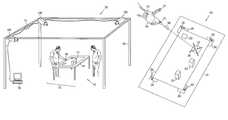
- FIG. 1shows an example of one implementation of an environment 100 in which a user can view and select objects on a display.
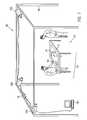
- FIG. 2shows an example of an interaction between an input device glove and an object projected by a display system.
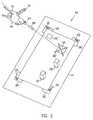
- FIG. 3illustrates an operation in which a user manipulates a displayed rectangle with the glove.
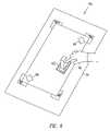
- FIG. 4illustrates a two-handed operation by which two-dimensional objects are moved to into corner positions.
- FIGS. 5A and 5Billustrate a poke operation through which a user can manipulate displayed two-dimensional objects.
- FIG. 6illustrates a poke operation through which a user can select a displayed three-dimensional object.
- FIG. 7is a flowchart showing a procedure for recognizing user input in an environment that displays three-dimensional images.
- FIG. 1shows an example of one implementation of an environment 100 in which a user can view and select objects on a display.
- the environmentincludes a display system 110 capable of displaying two- and three-dimensional holographic images, a set of detectors 120 A, 120 B, and 120 C (collectively, the detectors 120 ) that observes the region around the images from display system 110 , and a computer 130 coupled to detectors 120 .
- Each of the detectors 120includes an infrared emitter that generates a distinctly unique pulsed sequence of infrared illumination, and an infrared camera that receives infrared light.
- Detectors 120are securely mounted on a rigid frame 105 .
- Environment 100also includes at least one user-controlled indicator, which a user can use as an input device to indicate selections of objects displayed by display system 110 .
- the user-controlled indicatoris a glove 140 .
- Display system 110includes a computer-controlled projector 115 mounted on frame 105 , and a rectangular flat tabletop 111 illuminated by projector 115 .
- Projector 115is aimed, focused, and controlled to display two-dimensional objects on tabletop 111 .
- projector 115is controlled by the same computer 130 that is coupled to detectors 120 . It is also contemplated that two or more separate computers could be used to coordinate display and detection.
- Display system 110includes a hologram film 117 that displays three-dimensional objects when viewed by a user at appropriate angles and under appropriate lighting conditions.
- hologram film 117displays real images—that is, images that appear to a viewer to be located in a spatial location that is between the user and hologram film 117 . Such real images are useful, for example, to provide users with access to the displayed objects in a region of space where users can interact with the displayed objects.
- real imagesare used to present “aerial” views of geographic terrain potentially including symbols, people, animals, buildings, vehicles, and/or any objects that users can collectively point at and “touch” by intersecting hand-held pointers or fingers with the real images.
- hologram film 117is a reflection hologram recorded in a flexible sheet of polymer material.
- Hologram film 117is placed on flat tabletop 111 , so that projector 115 serves as the source of illumination, and so that the three-dimensional objects displayed by hologram film 117 appear to be co-located in an interaction region 150 along with the two-dimensional objects projected by projector 115 .
- the two-dimensional objectsmay be used to add cursors, text annotations, graphical annotations, topographic markings, roadmap features, graphical annotations, and other static or dynamic data to a static set of three-dimensional scenes or objects recorded in the hologram, such as a geographic terrain, cityscape, or architectural rendering.
- the two-dimensional objectsinclude cursors, pointers, graphical symbols, text annotations, and movable images of people and vehicles and the three-dimensional objects include images of buildings, roads, vehicles and bridges based on data taken from actual urban environments.
- the three-dimensional imagesinclude hills and valleys based on data taken from actual rural environments in which various rainfall distributions are anticipated, and the two-dimensional objects include renderings of the resulting water flows based on hydrology simulations.
- detectors 120gather data on the position in three-dimensional space of glove 140 , as well as data on any poses made by the arrangement of the fingers of the glove. As the user moves, rotates, and flexes the glove around interaction region 150 , detectors 120 and computer 130 use the collected data on the time-stamped locations and poses of the glove to detect various gestures made by the motion of the glove. Further information on gesture detection is available in U.S. Provisional Patent Application No. 60/651,290 by John Underkoffler, filed Feb. 8, 2005 and titled “Gesture based control system,” and in U.S. patent application Ser. No. 11/350,697 by John S. Underkoffler and Kevin T. Parent, filed Feb. 8, 2006 and titled “System and method for gesture based control system” (collectively referred to herein as the “Underkoffler references”).
- FIG. 2shows an example of an interaction between glove 140 and an object 231 projected by display system 110 in environment 100 (from FIG. 1 ), and as further described in the Underkoffler references.
- a user wearing the glovemakes a “gun” pose, with the index finger and thumb extended at an approximately 90° angle and the other fingers curled towards the palm of the hand.
- the gun poseis used to point at locations and objects displayed on tabletop 111 .
- the usercan drop the thumb of the gun pose into a closed position approximately parallel to the index finger. This motion is understood by detectors 120 and computer 130 as a gesture that selects an object at which the gun pose is pointing.
- These objectsare displayed on tabletop 111 in FIG. 2 . These object include two 2-dimensional rectangular objects 231 and 232 , which are projected through the computer-controlled projector 115 . These objects also include two 3-dimensional static objects 221 and 222 (two rectangular blocks), which are visible to a user who views hologram film 117 from appropriate angles.
- the useruses the gun pose to point at object 231 on tabletop 111 .
- Object 231is a computer-generated two-dimensional rectangle projected by the computer-controlled projector 115 from FIG. 1 .
- computer-controlled projector 115also displays a two-dimensional cursor 240 that moves along with a location where the gun pose points on tabletop 111 , as further described in the Underkoffler references. The user can then orient the gun pose of glove 140 so that the cursor 240 intersects the desired object, such as two-dimensional object 231 .
- Environment 100carries out a variety of operations so that computer 130 is able to detect such interactions between a user and the displayed objects. For example, detecting that a user is employing glove 140 to point at object 221 involves (a) gathering information on the location and spatial extents of object 221 and other objects being displayed, (b) gathering information on the location and pose of glove 140 , (c) performing a calculation to identify a vector along which glove 140 is pointing, and (d) determining that the location of object 221 coincides with those coordinates.
- detecting that a user is employing glove 140 to point at object 221involves (a) gathering information on the location and spatial extents of object 221 and other objects being displayed, (b) gathering information on the location and pose of glove 140 , (c) performing a calculation to identify a vector along which glove 140 is pointing, and (d) determining that the location of object 221 coincides with those coordinates.
- the following discussionaddresses each of these operations. Additional information is also available in the Underkoffler references.
- Various techniquesmay be used to gather information on the location and spatial extents of the objects displayed by display system 110 .
- One approachrequires a stable mounting of computer-controlled projector 115 on frame 105 and a stable location of tabletop 111 , fixed with respect to frame 105 .
- the location of tabletop 111 and the location and orientation of projector 115can then be measured relative to detectors 120 , which are also stably mounted on frame 105 .
- This relative location informationcan be entered into computer 130 . Since tabletop 111 defines the display region for the two- and three-dimensional images, computer 130 is thus made aware of the location of the display surface for the images.
- the location of two-dimensional objects on the display surfaceis known to computer 130 (from FIG.
- this computeris the device that controls the projection of the two-dimensional objects through projector 115 .
- projector 115can be manually or automatically adjusted to maintain a proper alignment, and/or the projector information can be recalibrated to compensate for drifts in the projector alignment.
- hologram film 117can be rigidly mounted onto tabletop 111 , so that the three-dimensional objects displayed by the hologram film are fixed with well-defined locations relative to tabletop 111 , frame 105 , and detectors 120 .
- Data concerning the three-dimensional objects encoded in the hologram film 117can be entered into computer 130 . These data describe the apparent locations of the three-dimensional objects with respect to hologram film 117 . These data are combined with data regarding the mounting position of hologram film 117 with respect to tabletop 111 . As a result, computer 130 can calculate the apparent locations of the three-dimensional objects with respect to tabletop 111 , and thus, with respect to the interaction region 150 in which the two- and three-dimensional images appear to a user. This information allows computer 130 to carry out a registration with 1:1 scaling and coincident spatial overlap of the three-dimensional objects with the interaction region 150 .
- the tabletopmay be equipped with mounting brackets 261 , 262 , 263 , and 264 , which fix the position of two diagonal corners of a hologram film on tabletop 111 .
- a second approachis also contemplated for gathering information on the location and spatial extents of the displayed two- and three-dimensional objects.
- This approachis similar to the approach described above, but can be used to relax the requirement of a fixed location for tabletop 111 .
- tabletop 111does not need to have a fixed known location relative to frame 105 and detectors 120 .
- detectors 120are used to determine the location and orientation of tabletop 111 during regular operation.
- detectors 120are capable of repeatedly ascertaining the location and orientation of tabletop 111 , so that even if tabletop 111 is shifted, spun, or tilted, the relevant position information can be gathered and updated as needed.
- detectors 120 and computer 130can determine the location of tabletop 111 .
- the tagscan be implemented, for example, using small retroreflecting beads, with the beads arranged in unique patterns for each tag.
- tabletop 111has four distinct visible tags 251 , 252 , 253 , and 254 . These tags are shown as combinations of dots arranged in four different geometric patterns, placed at the four corners of tabletop 111 .
- the tagsare mounted on the four brackets 261 , 262 , 263 , and 264 , which are fixed onto tabletop 111 .
- Tabletop 111is constructed of rigid material, so that the four tags have a fixed spatial relationship (distance and direction) with respect to each other and to the tabletop. Measurements regarding the location of these four tags relative to each other and to the spatial extents of the tabletop are pre-entered into computer 130 . When detectors 120 detect the locations in three-space of the four tags, these locations can be provided to computer 130 . Using the pre-entered tabletop measurements, computer 130 can then deduce the location, azimuthal orientation, and inclination of tabletop 111 . In one implementation, the computer uses the spatial location of at least three of the tags to identify a plane of the tabletop. In another implementation, the computer uses the spatial orientation of at least one of the tags to identify the plane of the tabletop.
- Detectors 120use pulsed infrared imaging and triangulation to ascertain the locations of each of the tags 251 , 252 , 253 , and 254 . Additional information is also available in the Underkoffler references.
- Each of the detectors 120 A, 120 B, and 120 Cilluminates the region around tabletop 111 periodically with a pulse of infrared light. The reflected light is collected by the emitting detector and imaged on a charge coupled device (or other suitable type of sensor). Circuitry in each detector identifies the four tags based on their unique patterns; the data from the three cameras is then combined to calculate the position in three-space of each of the four tags. Additional detectors may also be used.
- the additional detector(s)provides some flexibility in situations where one of the other detectors has an obscured view, and may also provide additional data that can improve the accuracy of the triangulation calculations.
- environment 100uses eight detectors to gather data from the interaction region 150 .
- Detectors 120may include motion capture detectors that use infrared pulses to detect locations of retroreflecting tags. Such devices are available, for example, from Vicon Limited in Los Angeles, Calif. The infrared pulses may be flashes with repetition rates of approximately 90 Hz, with a coordinated time-base operation to isolate the data acquisition among the various detectors.
- Tags 251 , 252 , 253 , and 254may be implemented using passive retroreflecting beads with dimensions of approximately 1 mm. With spherical beads and appropriate imaging equipment, a spatial resolution of approximately 0.5 mm may be obtained for the location of the tags. Further information on the operation of an infrared location system is available in the Underkoffler references.
- Detectors 120can be configured to make fast regular updates of the locations of tags 251 , 252 , 253 , and 254 .
- computer 130can be updated if the location of the tags, and therefore of tabletop 111 moves over time.
- This configurationcan be used to enable a rotating tabletop.
- the hologram film 117 used in display system 110is configured to be viewed under normal illumination, from a direction perpendicular to the film. (For example, hologram film 117 can be constructed using optics in which a reference beam normally illuminates the hologram film.).
- display system 110includes a light source (not shown) that is mounted directly above tabletop 111 to provide normal illumination.
- tabletop 111can be readily mounted on a rotating support, so that tabletop 111 , and the hologram film mounted thereon, can be rotated for the convenience of users.
- hologram film 117As hologram film 117 is rotated, the overhead light source continues to serve as a properly angled source of illumination.
- Detectors 120 and computer 130can also be used to gather information on the location and pose of glove 140 , as described in the Underkoffler references. Additional tags 211 , 212 , and 213 are depicted in FIG. 2 as being attached on the thumb, index finger, and wrist, respectively, of glove 140 in this example. Additional tags may also be used on glove 140 . By obtaining the three-space location of the tags, detectors 120 obtain position information for the points on the glove to which they are attached.
- detectors 120 and computer 130can use the three-space positions of tags 211 , 212 , and 213 to determine the location, pose, and gesturing of the glove, as described in the Underkoffler references.
- the three-space positions of the glove-mounted tags 211 , 212 , and 213indicate where glove 140 is located and also that glove 140 is being held in a gun pose. That is, the positions of the glove-mounted tags, relative to each other, indicate that the index finger is extended and the thumb is being held away from the index finger in this example.
- the pose of glove 140can similarly be deduced from the information about the positions of tags 211 , 212 , and 213 .
- the posemay be characterized, for example, by angles that describe the inclination of the pointing index finger (e.g., the direction of a vector between tags 212 and 213 ), and the inclination of the extended thumb (using tags 211 and 212 and appropriate anatomical information).
- computer 130can proceed to identify coordinates at which glove 140 is pointing. That is, computer 130 can use the position information of tags 211 , 212 , and 213 and appropriate anatomical information to calculate a vector 280 along which a user is pointing, as described in the Underkoffler references.
- Computer 130then performs a calculation to determine which object(s), if any, have coordinates along the vector 280 . This calculation uses the information about the positions of the two- and three-dimensional objects, and also employs data regarding the extents of these objects. If the vector 280 intersects the extents of an object, computer 130 (from FIG. 1 ) ascertains that the user is pointing at that object. In the example of FIG. 2 , the computer ascertains that the user is pointing at two-dimensional object 231 . Visual feedback can be provided to the user, for example by causing object 231 to visibly undulate (not shown) when the user points at object 231 . In addition or instead, auditory feedback, for example using a beep sound generated by a speaker coupled to computer 130 , can also be provided to show that the user is pointing at an object.
- FIG. 3illustrates an operation in which a user manipulates a displayed object 231 with glove 140 .
- object 231has been repositioned.
- This operationinvolves the user selecting the object by changing the pose of glove 140 , and moving the object by a motion of the glove.
- a userchanges the pose of the glove from an open gun to a closed gun by bringing the thumb close to the index finger while pointing at object 231 .
- This motionis interpreted as a gesture that selects object 231 .
- Detectors 120detect the resulting locations of tags 211 , 212 , and 213 on the glove, and pass these locations on to computer 130 .
- Computer 130determines that the locations of the tags have changed relative to each other and recognizes the change as indicating a selection gesture. Since the user is pointing at cross-shaped object 231 while the selection gesture is performed, computer 130 deems this object 231 to be selected by the user.
- Visual feedbackcan be provided to the user, for example by displaying a two-dimensional highlight border 341 around object 231 to indicate that the user has selected object 231 .
- auditory feedbackfor example using a beep sound, can also be provided to show that the user has selected an object.
- Visual and auditory feedback for selected objectsare also contemplated, such as a change in size, a geometric pulsing, an encircling, a change in color, or a flashing of the selected object, or an auditory chime, bell, or other alert sound, or others, or some combination thereof.
- various forms of visual feedbackcan also be provided when a user points at a displayed object.
- computer 130can also change the image projected through projector 115 in response to a change in location or pose of glove 140 .
- the userhas changed the direction at which the glove points; the direction of pointing 380 is different in FIG. 3 than it was ( 280 ) in FIG. 2 .
- This motionis used in the illustrated example to move a selected object across the surface of tabletop 111 .
- object 231has been repositioned accordingly. The user may de-select object 231 in the new location by raising the thumb (not shown), thereby returning glove 140 to the open gun pose.
- Computer 130would respond accordingly by removing the highlight border 341 from object 231 in the new position.
- the user-directed repositioning of two-dimensional objectsmay be usable, for example, to control the placement of two-dimensional shapes, text, or other overlay features displayed in conjunction with a three-dimensional holographic image.
- Other user-directed operations on the displayed objectsare also contemplated, such as arranging various two-dimensional objects in home positions arrayed in a grid or in a circular pattern.
- Various operationscan be done with right-hand gestures, left-hand gestures, or simultaneously with both hands. More than two hands simultaneously are even possible, i.e. with multiple users.
- various operationsmay be performed based on collaborative gestures that involve a one-handed gesture from a user along with another one-handed gesture from another user.
- multi-user gesturesmay be involve more than two users and/or one or two-handed gestures by the users, as described in the Underkoffler references.
- FIG. 4illustrates a two-handed operation by which two-dimensional objects are moved to into corner positions.
- a useremploys two gloves, 140 and 440 , each with appropriately mounted tags that can be recognized and individually identified by detectors 120 .
- computer 130recognizes this gesture as a return-to-corner command, as described in the Underkoffler references.
- computer 130causes the objects 231 and 232 to move to adjacent corners of tabletop 111 .
- FIGS. 5A , 5 B, and 6illustrate other types of operations through which a user can manipulate displayed objects.
- a usertouches tabletop 111 with the extended index finger of glove 140 .
- the usertouches the location where object 342 is displayed.
- This position and pose of the gloveis interpreted as a selection of object 232 by “poking” the object 232 .
- Visual feedback and auditoryis provided to the user by displaying a two-dimensional highlight border 542 around object 232 and sounding a chime to indicate that the user has selected rectangle 542 .
- the userthen drags the index finger of glove 140 to a new location on the surface of tabletop 111 .
- Computer 130responds by causing object 232 to be projected as moving along with the user's index finger, thereby displaying the dragging of the object a new position, shown in FIG. 5B .
- FIG. 6shows another operation, in which a user selects a three-dimensional object by poking the three-dimensional object.
- the usertouches three-dimensional object 222 with the index finger of glove 140 .
- the locations of the tags on glove 140are detected by detectors 120 , which pass the location information on to computer 130 .
- Computer 130uses this location information, in combination with location information of the tags mounted on tabletop 111 , to ascertain that the user's fingertip has intersected the extents of three-dimensional object 222 .
- Visual and auditory feedbackis provided to the user, in this example by displaying a two-dimensional highlight border 622 around object 222 and by sounding an audible beep.
- FIG. 7is a flowchart showing a procedure for recognizing user input in an environment that displays three-dimensional images.
- the procedurecommences in act 710 by displaying a static, digitally generated, three-dimensional, autostereoscopic, full-parallax, real image.
- the imagemay be produced by a holographic film that is securely mounted onto a tabletop in an interaction region that is accessible to users.
- two-dimensional shapesare displayed in alignment with the three-dimensional image.
- the procedurecontinues in act 720 by detecting tags mounted on a glove worn by a user, and by determining the location and pose of the glove based on the tags.
- the proceduredetects tags mounted with a fixed relationship to the three-dimensional image. For example, these, tags can be fixed to particular locations of the tabletop. Based on these tags, a determination is made of the location and orientation of the tabletop.
- the procedurecalculates a location of a feature of the three-dimensional image. This calculation is based on the location and orientation of the tabletop, and on data describing the features shown in the three-dimensional image.
- the procedurethen calculates a distance and direction between the glove and the feature of the three-dimensional image, based on the location of the tags.
- the proceduremay identify an intersection of the input device with the feature of the three-dimensional image based on the distance and direction between the glove and the feature of the three-dimensional image. Other operations are also contemplated. For example, in act 745 the procedure identifies a user input based on a gestural motion of the glove. In act 750 , the procedure identifies a feature of the image in response to a user using the glove to point at the feature of the image, and in act 755 the procedure identifies the feature of the image in response to a user using the glove to poke the feature of the image.
- FIGS. 1-7illustrate some of the many operational examples of the techniques disclosed in the present application. Those having ordinary skill in the art will readily recognize that certain steps or operations described herein may be eliminated or taken in an alternate order. Moreover, the operations discussed with respect to FIGS. 1-6 may be implemented as one or more software programs for a computer system and encoded in a computer readable medium as instructions executable on one or more processors.
- the computer readable mediummay include a solid-state storage medium, a magnetic storage medium, or an optical storage medium, or combinations thereof.
- the software programsmay also be carried in a communications medium conveying signals encoding the instructions. Separate instances of these programs may be executed on separate computer systems.
- the softwaremay be provided to the computer system via a variety of computer readable media including electronic media (e.g., flash memory), magnetic storage media (e.g., hard disk, a floppy disk, etc.), or optical storage media (e.g., CD-ROM).
- Communications mediaconveying signals encoding the instructions may also be used to provide the software (e.g., via a network coupled to a network interface).
Landscapes
- Engineering & Computer Science (AREA)
- General Engineering & Computer Science (AREA)
- Theoretical Computer Science (AREA)
- Physics & Mathematics (AREA)
- General Physics & Mathematics (AREA)
- Human Computer Interaction (AREA)
- Position Input By Displaying (AREA)
- User Interface Of Digital Computer (AREA)
Abstract
Description
Claims (23)
Priority Applications (1)
| Application Number | Priority Date | Filing Date | Title |
|---|---|---|---|
| US12/050,527US8233206B2 (en) | 2008-03-18 | 2008-03-18 | User interaction with holographic images |
Applications Claiming Priority (1)
| Application Number | Priority Date | Filing Date | Title |
|---|---|---|---|
| US12/050,527US8233206B2 (en) | 2008-03-18 | 2008-03-18 | User interaction with holographic images |
Publications (2)
| Publication Number | Publication Date |
|---|---|
| US20090237763A1 US20090237763A1 (en) | 2009-09-24 |
| US8233206B2true US8233206B2 (en) | 2012-07-31 |
Family
ID=41088626
Family Applications (1)
| Application Number | Title | Priority Date | Filing Date |
|---|---|---|---|
| US12/050,527Expired - Fee RelatedUS8233206B2 (en) | 2008-03-18 | 2008-03-18 | User interaction with holographic images |
Country Status (1)
| Country | Link |
|---|---|
| US (1) | US8233206B2 (en) |
Cited By (6)
| Publication number | Priority date | Publication date | Assignee | Title |
|---|---|---|---|---|
| US20140282267A1 (en)* | 2011-09-08 | 2014-09-18 | Eads Deutschland Gmbh | Interaction with a Three-Dimensional Virtual Scenario |
| US10025099B2 (en) | 2015-06-10 | 2018-07-17 | Microsoft Technology Licensing, Llc | Adjusted location hologram display |
| US10573056B2 (en) | 2017-03-06 | 2020-02-25 | 3D Patents, Llc | Multi-view processing unit systems and methods |
| TWI701941B (en)* | 2018-12-21 | 2020-08-11 | 大陸商北京市商湯科技開發有限公司 | Method, apparatus and electronic device for image processing and storage medium thereof |
| US10824293B2 (en) | 2017-05-08 | 2020-11-03 | International Business Machines Corporation | Finger direction based holographic object interaction from a distance |
| US11796959B2 (en) | 2019-01-25 | 2023-10-24 | International Business Machines Corporation | Augmented image viewing with three dimensional objects |
Families Citing this family (26)
| Publication number | Priority date | Publication date | Assignee | Title |
|---|---|---|---|---|
| US20080231926A1 (en)* | 2007-03-19 | 2008-09-25 | Klug Michael A | Systems and Methods for Updating Dynamic Three-Dimensional Displays with User Input |
| IT1397737B1 (en)* | 2010-01-18 | 2013-01-24 | Giovanni Saggio | EQUIPMENT AND METHOD OF DETECTION, TRAINING AND TRAINING OF MOTOR ACTIVITIES |
| GB2481366B (en)* | 2010-06-03 | 2014-05-28 | Sony Comp Entertainment Europe | Entertainment device and entertainment methods |
| US8508347B2 (en)* | 2010-06-24 | 2013-08-13 | Nokia Corporation | Apparatus and method for proximity based input |
| US9851829B2 (en)* | 2010-08-27 | 2017-12-26 | Apple Inc. | Signal processing for touch and hover sensing display device |
| ES2693060T3 (en)* | 2011-03-17 | 2018-12-07 | Ssi Schäfer Automation Gmbh | Control and supervision of a warehouse installation and order preparation through movement and voice |
| JP5880916B2 (en) | 2011-06-03 | 2016-03-09 | ソニー株式会社 | Information processing apparatus, information processing method, and program |
| US9019240B2 (en) | 2011-09-29 | 2015-04-28 | Qualcomm Mems Technologies, Inc. | Optical touch device with pixilated light-turning features |
| US9032334B2 (en)* | 2011-12-21 | 2015-05-12 | Lg Electronics Inc. | Electronic device having 3-dimensional display and method of operating thereof |
| US9449433B2 (en) | 2012-02-22 | 2016-09-20 | Ming Fong | System for reproducing virtual objects |
| US20130215132A1 (en)* | 2012-02-22 | 2013-08-22 | Ming Fong | System for reproducing virtual objects |
| US20140002336A1 (en)* | 2012-06-27 | 2014-01-02 | Greg D. Kaine | Peripheral device for visual and/or tactile feedback |
| KR101950939B1 (en)* | 2012-09-13 | 2019-02-22 | 삼성전자주식회사 | Apparatus and and method for processing Holograghic Object |
| JP6138566B2 (en)* | 2013-04-24 | 2017-05-31 | 川崎重工業株式会社 | Component mounting work support system and component mounting method |
| WO2015004670A1 (en)* | 2013-07-10 | 2015-01-15 | Real View Imaging Ltd. | Three dimensional user interface |
| US9530057B2 (en)* | 2013-11-26 | 2016-12-27 | Honeywell International Inc. | Maintenance assistant system |
| US20150185858A1 (en)* | 2013-12-26 | 2015-07-02 | Wes A. Nagara | System and method of plane field activation for a gesture-based control system |
| US9958829B2 (en)* | 2014-05-07 | 2018-05-01 | International Business Machines Corporation | Sensory holograms |
| US20160282947A1 (en)* | 2015-03-26 | 2016-09-29 | Lenovo (Singapore) Pte. Ltd. | Controlling a wearable device using gestures |
| US10564770B1 (en) | 2015-06-09 | 2020-02-18 | Apple Inc. | Predictive touch detection |
| US10895950B2 (en) | 2016-12-09 | 2021-01-19 | International Business Machines Corporation | Method and system for generating a holographic image having simulated physical properties |
| EP3826741A4 (en)* | 2018-07-25 | 2022-08-10 | Light Field Lab, Inc. | Light field display system based amusement park attraction |
| US10921950B1 (en) | 2019-08-07 | 2021-02-16 | Ford Global Technologies, Llc | Pointing and interaction control devices for large scale tabletop models |
| CN110825271B (en)* | 2019-11-13 | 2024-07-16 | 一汽奔腾轿车有限公司 | Vehicle-mounted AR holographic projection interaction device |
| CN111870278B (en)* | 2020-08-26 | 2025-02-07 | 居天智慧(深圳)有限公司 | Ultrasonic scanning holographic projection equipment |
| DE102023133037A1 (en) | 2023-11-27 | 2025-05-28 | Carl Zeiss Jena Gmbh | Holographic light field display system |
Citations (14)
| Publication number | Priority date | Publication date | Assignee | Title |
|---|---|---|---|---|
| US5687307A (en) | 1993-09-21 | 1997-11-11 | Canon Kabushiki Kaisha | Computer graphic animation in which texture animation is independently performed on a plurality of objects in three-dimensional space |
| US6195104B1 (en) | 1997-12-23 | 2001-02-27 | Philips Electronics North America Corp. | System and method for permitting three-dimensional navigation through a virtual reality environment using camera-based gesture inputs |
| US6330088B1 (en) | 1998-02-27 | 2001-12-11 | Zebra Imaging, Inc. | Method and apparatus for recording one-step, full-color, full-parallax, holographic stereograms |
| US20040046736A1 (en) | 1997-08-22 | 2004-03-11 | Pryor Timothy R. | Novel man machine interfaces and applications |
| US6750848B1 (en) | 1998-11-09 | 2004-06-15 | Timothy R. Pryor | More useful man machine interfaces and applications |
| US6795241B1 (en) | 1998-12-10 | 2004-09-21 | Zebra Imaging, Inc. | Dynamic scalable full-parallax three-dimensional electronic display |
| US6859293B2 (en) | 2002-10-22 | 2005-02-22 | Zebra Imaging, Inc. | Active digital hologram display |
| US20060001650A1 (en) | 2004-06-30 | 2006-01-05 | Microsoft Corporation | Using physical objects to adjust attributes of an interactive display application |
| US20060187196A1 (en) | 2005-02-08 | 2006-08-24 | Underkoffler John S | System and method for gesture based control system |
| US20070048702A1 (en)* | 2005-08-25 | 2007-03-01 | Jang Gil S | Immersion-type live-line work training system and method |
| US7190496B2 (en) | 2003-07-24 | 2007-03-13 | Zebra Imaging, Inc. | Enhanced environment visualization using holographic stereograms |
| US20080144174A1 (en) | 2006-03-15 | 2008-06-19 | Zebra Imaging, Inc. | Dynamic autostereoscopic displays |
| US20080170293A1 (en) | 2006-03-15 | 2008-07-17 | Lucente Mark E | Dynamic autostereoscopic displays |
| US20080231926A1 (en) | 2007-03-19 | 2008-09-25 | Klug Michael A | Systems and Methods for Updating Dynamic Three-Dimensional Displays with User Input |
- 2008
- 2008-03-18USUS12/050,527patent/US8233206B2/ennot_activeExpired - Fee Related
Patent Citations (14)
| Publication number | Priority date | Publication date | Assignee | Title |
|---|---|---|---|---|
| US5687307A (en) | 1993-09-21 | 1997-11-11 | Canon Kabushiki Kaisha | Computer graphic animation in which texture animation is independently performed on a plurality of objects in three-dimensional space |
| US20040046736A1 (en) | 1997-08-22 | 2004-03-11 | Pryor Timothy R. | Novel man machine interfaces and applications |
| US6195104B1 (en) | 1997-12-23 | 2001-02-27 | Philips Electronics North America Corp. | System and method for permitting three-dimensional navigation through a virtual reality environment using camera-based gesture inputs |
| US6330088B1 (en) | 1998-02-27 | 2001-12-11 | Zebra Imaging, Inc. | Method and apparatus for recording one-step, full-color, full-parallax, holographic stereograms |
| US6750848B1 (en) | 1998-11-09 | 2004-06-15 | Timothy R. Pryor | More useful man machine interfaces and applications |
| US6795241B1 (en) | 1998-12-10 | 2004-09-21 | Zebra Imaging, Inc. | Dynamic scalable full-parallax three-dimensional electronic display |
| US6859293B2 (en) | 2002-10-22 | 2005-02-22 | Zebra Imaging, Inc. | Active digital hologram display |
| US7190496B2 (en) | 2003-07-24 | 2007-03-13 | Zebra Imaging, Inc. | Enhanced environment visualization using holographic stereograms |
| US20060001650A1 (en) | 2004-06-30 | 2006-01-05 | Microsoft Corporation | Using physical objects to adjust attributes of an interactive display application |
| US20060187196A1 (en) | 2005-02-08 | 2006-08-24 | Underkoffler John S | System and method for gesture based control system |
| US20070048702A1 (en)* | 2005-08-25 | 2007-03-01 | Jang Gil S | Immersion-type live-line work training system and method |
| US20080144174A1 (en) | 2006-03-15 | 2008-06-19 | Zebra Imaging, Inc. | Dynamic autostereoscopic displays |
| US20080170293A1 (en) | 2006-03-15 | 2008-07-17 | Lucente Mark E | Dynamic autostereoscopic displays |
| US20080231926A1 (en) | 2007-03-19 | 2008-09-25 | Klug Michael A | Systems and Methods for Updating Dynamic Three-Dimensional Displays with User Input |
Non-Patent Citations (21)
| Title |
|---|
| "Blue-C," project web page, http://blue-c.ethz.ch, 1 page, downloaded Apr. 14, 2009. |
| "Hitachi shows off new stereoscopic vision display technology," 3rd Dimension, Veritas et Visus, Temple, Texas, p. 15, Sep. 2007. |
| Bolt, Richard A., "'Put-That-There': Voice and Gesture at the Graphics Interface," International Conference on Computer Graphics and Interactive Techniques, pp. 262-270, Seattle, Jul. 14-18, 1980. |
| Businessweek Archives, "Let's Talk!," Speech technology is the next big thing in computing. Will it put a PC in every home? hap://www.businessweek.com/1998/08/b3566001.htm, 1998, 12 pages. |
| Gross, Markus, et al., preprint: "blue-c: A Spatially Immersive Display and 3D Video Portal for Telepresence," ACM SIGGRAPH 2003: International Conference on Computer Graphics and Interactive Techniques, ACM Press, pp. 819-827, 2003. |
| Gross, Markus, web page for "blue-c: A Spatially Immersive Display and 3D Video Portal for Telepresence," http://www.inf.ethz.ch/news/focus/res-focus/jun-2004, pp. 1-4, Aug. 22, 2005. |
| Grossman, Tovi et al., "Pointing at Trivariate Targets in 3D Environments," CHI 2004 Conference Proceedings: ACM Conference on Human Factors in Computing Systems, pp. 447-454, 2004. |
| Grossman, Tovi, et al., "Multi-Finger Gestural Interaction with 3D Volumetric Displays," Proceedings of the 17th Annual ACM Symposium on User Interface Software and Technology, vol. 6, No. 2, Santa Fe, NM, pp. 61-70, Oct. 24-27, 2004. |
| Grossman, Tovi, home page, http://www.dgp.toronto.edu/~tovi/, pp. 1-6, Apr. 14, 2009. |
| Grossman, Tovi, home page, http://www.dgp.toronto.edu/˜tovi/, pp. 1-6, Apr. 14, 2009. |
| Harris, Michael; Moderator, NCR Human Interface Technology Center, "Interfaces for Humans: Natural Interaction, Tangible Data, and Beyond," Panels Conference Abstracts and Applications http://tangible.media.mit.edu/content/papers/pdf/panel-1-SG98.pdf, pp. 200-202. |
| Holzbach, Mark E. et al., "Multi-Core Porcessor Architercture for Active Autostereoscopic Emmisive Displays," U.S. Appl. No. 11/949,763, filed Dec. 3, 2007, consisting of Specification, Claims and Abstract (29 pages); and Drawings (5 sheets). |
| IBM Corporation, IBM Research: DreamSpace: natural interaction,: http://www.lucente.us/career/natural/dreamspace/index.html, 1995, pp. 1-8. |
| Lucente, Mark, "IBM Plans a Magic Show for the Folks at Comdex," Mark Lucente-popular press: The Wall Street Journal, Monday, Nov. 17, 1997 article by Staff Reporter Raju Narisetti, http://www.lucente.us/press/1997wsj/index.html, 3 pages. |
| Lucente, Mark, et al., "Visualization Space: A Testbed for Deviceless Multimodal User Interface," IBM Research, Presented at Intelligent Environments Symposium, American Assoc. for Artificial Intelligence Spring Symposium Series, Mar. 23-25, 1998 at Stanford University, http://www.lucente.us/pubs/IE98.pdf, 6 pages. |
| Lucente, Mark-popular press: BusinessWeek Cover Story, 1998, Feb 23 "Let's Talk!" BusinessWeek cover story http://www.lucente.us/press/1998bw/BW1998.html, 3 pages. |
| Pfister, Hanspeter, web page for "3D Video at ETH Zurich," http://graphics.ethz.ch/research/past-projects/3dvideo/ (forwarded from http://graphics.ethz.ch/3dvideo), 1 page, 2004. |
| R. Narisetti, "IBM Plans a Magic Show for the Folks at Comdex," The Wall Street Journal, Nov. 17, 1997, 3 pages. |
| Tovi Grossman et al., "The design and evaluation of selection techniques for 3D volumetric displays," UIST 2006 Proceedings: ACM Symposium on User Interface Software and Technology, pp. 3-12, 2006. |
| Wigdor, Daniel, et al., "Effects of Display Position and Control Space Orientation on User Preference and Performance," CHI 06: Proceedings of the SIGCHI Conference on Human Factors in Computing Systems, Montréal, Québec, 10 pages, Apr. 22-27, 2006. |
| Wigdor, Daniel, et al., "Table-Centric Interactive spaces for Real-time Collaboration," Proceedings of the working conference on Advanced visual interfaces, Venezia, Italy, pp. 103-107, May 23-26, 2006. |
Cited By (8)
| Publication number | Priority date | Publication date | Assignee | Title |
|---|---|---|---|---|
| US20140282267A1 (en)* | 2011-09-08 | 2014-09-18 | Eads Deutschland Gmbh | Interaction with a Three-Dimensional Virtual Scenario |
| US10025099B2 (en) | 2015-06-10 | 2018-07-17 | Microsoft Technology Licensing, Llc | Adjusted location hologram display |
| US10573056B2 (en) | 2017-03-06 | 2020-02-25 | 3D Patents, Llc | Multi-view processing unit systems and methods |
| US10937223B2 (en) | 2017-03-06 | 2021-03-02 | 3D Patents, Llc | Multi-view processing unit systems and methods |
| US11423599B2 (en) | 2017-03-06 | 2022-08-23 | 3D Patents, Llc | Multi-view processing unit systems and methods |
| US10824293B2 (en) | 2017-05-08 | 2020-11-03 | International Business Machines Corporation | Finger direction based holographic object interaction from a distance |
| TWI701941B (en)* | 2018-12-21 | 2020-08-11 | 大陸商北京市商湯科技開發有限公司 | Method, apparatus and electronic device for image processing and storage medium thereof |
| US11796959B2 (en) | 2019-01-25 | 2023-10-24 | International Business Machines Corporation | Augmented image viewing with three dimensional objects |
Also Published As
| Publication number | Publication date |
|---|---|
| US20090237763A1 (en) | 2009-09-24 |
Similar Documents
| Publication | Publication Date | Title |
|---|---|---|
| US8233206B2 (en) | User interaction with holographic images | |
| Cao et al. | Mobile augmented reality: User interfaces, frameworks, and intelligence | |
| Costanza et al. | Mixed reality: A survey | |
| US20080231926A1 (en) | Systems and Methods for Updating Dynamic Three-Dimensional Displays with User Input | |
| TWI722280B (en) | Controller tracking for multiple degrees of freedom | |
| Zhou et al. | Trends in augmented reality tracking, interaction and display: A review of ten years of ISMAR | |
| CN114080585A (en) | Virtual user interface using peripherals in artificial reality | |
| JP5950130B2 (en) | Camera-type multi-touch interaction device, system and method | |
| US6775014B2 (en) | System and method for determining the location of a target in a room or small area | |
| US9292089B1 (en) | Gestural object selection | |
| KR101823182B1 (en) | Three dimensional user interface effects on a display by using properties of motion | |
| EP1292877B1 (en) | Apparatus and method for indicating a target by image processing without three-dimensional modeling | |
| Winkler et al. | Pervasive information through constant personal projection: the ambient mobile pervasive display (AMP-D) | |
| AU2017261608A1 (en) | Method for representing points of interest in a view of a real environment on a mobile device and mobile device therefor | |
| US20120194561A1 (en) | Remote control of computer devices | |
| JP2013054661A (en) | Information display system, information display method and program for information display | |
| EP3283938A1 (en) | Gesture interface | |
| Shirazi et al. | Flashlight interaction: a study on mobile phone interaction techniques with large displays | |
| Herman et al. | Multi-touch querying on data physicalizations in immersive AR | |
| JP2004265222A (en) | Interface method, apparatus, and program | |
| Schmalstieg et al. | Augmented reality as a medium for cartography | |
| Chan et al. | Enabling beyond-surface interactions for interactive surface with an invisible projection | |
| Livingston | Vision-based tracking with dynamic structured light for video see-through augmented reality | |
| Cheliotis et al. | A classification of augmented reality approaches for spatial data visualization | |
| WO2022129646A1 (en) | Virtual reality environment |
Legal Events
| Date | Code | Title | Description |
|---|---|---|---|
| AS | Assignment | Owner name:ZEBRA IMAGING, INC., TEXAS Free format text:ASSIGNMENT OF ASSIGNORS INTEREST;ASSIGNORS:KLUG, MICHAEL A.;HOLZBACH, MARK E.;KRAMER, KWINDLA H.;AND OTHERS;REEL/FRAME:020667/0838;SIGNING DATES FROM 20080228 TO 20080317 Owner name:ZEBRA IMAGING, INC., TEXAS Free format text:ASSIGNMENT OF ASSIGNORS INTEREST;ASSIGNORS:KLUG, MICHAEL A.;HOLZBACH, MARK E.;KRAMER, KWINDLA H.;AND OTHERS;SIGNING DATES FROM 20080228 TO 20080317;REEL/FRAME:020667/0838 | |
| STCF | Information on status: patent grant | Free format text:PATENTED CASE | |
| FPAY | Fee payment | Year of fee payment:4 | |
| AS | Assignment | Owner name:FOVI 3D, INC., TEXAS Free format text:ASSIGNMENT OF ASSIGNORS INTEREST;ASSIGNOR:ZEBRA IMAGING, INC.;REEL/FRAME:042391/0378 Effective date:20161020 | |
| AS | Assignment | Owner name:NUEVO CAPITAL PARTNERS, L.P., TEXAS Free format text:SECURITY INTEREST;ASSIGNOR:FOVI 3D, INC.;REEL/FRAME:048260/0043 Effective date:20190129 | |
| AS | Assignment | Owner name:3D PATENTS, LLC, KANSAS Free format text:ASSIGNMENT OF ASSIGNORS INTEREST;ASSIGNOR:FOVI3D, INC.;REEL/FRAME:050083/0745 Effective date:20190331 | |
| FEPP | Fee payment procedure | Free format text:MAINTENANCE FEE REMINDER MAILED (ORIGINAL EVENT CODE: REM.); ENTITY STATUS OF PATENT OWNER: SMALL ENTITY | |
| AS | Assignment | Owner name:3D VIRTUALIS KINCSTAR KFT., HUNGARY Free format text:ASSIGNMENT OF ASSIGNORS INTEREST;ASSIGNOR:3D PATENTS, LLC;REEL/FRAME:052887/0276 Effective date:20200302 | |
| FEPP | Fee payment procedure | Free format text:7.5 YR SURCHARGE - LATE PMT W/IN 6 MO, SMALL ENTITY (ORIGINAL EVENT CODE: M2555); ENTITY STATUS OF PATENT OWNER: SMALL ENTITY | |
| MAFP | Maintenance fee payment | Free format text:PAYMENT OF MAINTENANCE FEE, 8TH YR, SMALL ENTITY (ORIGINAL EVENT CODE: M2552); ENTITY STATUS OF PATENT OWNER: SMALL ENTITY Year of fee payment:8 | |
| FEPP | Fee payment procedure | Free format text:MAINTENANCE FEE REMINDER MAILED (ORIGINAL EVENT CODE: REM.); ENTITY STATUS OF PATENT OWNER: SMALL ENTITY | |
| LAPS | Lapse for failure to pay maintenance fees | Free format text:PATENT EXPIRED FOR FAILURE TO PAY MAINTENANCE FEES (ORIGINAL EVENT CODE: EXP.); ENTITY STATUS OF PATENT OWNER: SMALL ENTITY | |
| STCH | Information on status: patent discontinuation | Free format text:PATENT EXPIRED DUE TO NONPAYMENT OF MAINTENANCE FEES UNDER 37 CFR 1.362 | |
| FP | Lapsed due to failure to pay maintenance fee | Effective date:20240731 |