US8231649B2 - Retrievable blood clot filter with retractable anchoring members - Google Patents
Retrievable blood clot filter with retractable anchoring membersDownload PDFInfo
- Publication number
- US8231649B2 US8231649B2US10/762,643US76264304AUS8231649B2US 8231649 B2US8231649 B2US 8231649B2US 76264304 AUS76264304 AUS 76264304AUS 8231649 B2US8231649 B2US 8231649B2
- Authority
- US
- United States
- Prior art keywords
- filter
- blood clot
- filter device
- clot filter
- blood
- Prior art date
- Legal status (The legal status is an assumption and is not a legal conclusion. Google has not performed a legal analysis and makes no representation as to the accuracy of the status listed.)
- Expired - Fee Related, expires
Links
Images


Classifications
- A—HUMAN NECESSITIES
- A61—MEDICAL OR VETERINARY SCIENCE; HYGIENE
- A61F—FILTERS IMPLANTABLE INTO BLOOD VESSELS; PROSTHESES; DEVICES PROVIDING PATENCY TO, OR PREVENTING COLLAPSING OF, TUBULAR STRUCTURES OF THE BODY, e.g. STENTS; ORTHOPAEDIC, NURSING OR CONTRACEPTIVE DEVICES; FOMENTATION; TREATMENT OR PROTECTION OF EYES OR EARS; BANDAGES, DRESSINGS OR ABSORBENT PADS; FIRST-AID KITS
- A61F2/00—Filters implantable into blood vessels; Prostheses, i.e. artificial substitutes or replacements for parts of the body; Appliances for connecting them with the body; Devices providing patency to, or preventing collapsing of, tubular structures of the body, e.g. stents
- A61F2/01—Filters implantable into blood vessels
- A61F2/0105—Open ended, i.e. legs gathered only at one side
- A—HUMAN NECESSITIES
- A61—MEDICAL OR VETERINARY SCIENCE; HYGIENE
- A61F—FILTERS IMPLANTABLE INTO BLOOD VESSELS; PROSTHESES; DEVICES PROVIDING PATENCY TO, OR PREVENTING COLLAPSING OF, TUBULAR STRUCTURES OF THE BODY, e.g. STENTS; ORTHOPAEDIC, NURSING OR CONTRACEPTIVE DEVICES; FOMENTATION; TREATMENT OR PROTECTION OF EYES OR EARS; BANDAGES, DRESSINGS OR ABSORBENT PADS; FIRST-AID KITS
- A61F2/00—Filters implantable into blood vessels; Prostheses, i.e. artificial substitutes or replacements for parts of the body; Appliances for connecting them with the body; Devices providing patency to, or preventing collapsing of, tubular structures of the body, e.g. stents
- A61F2/01—Filters implantable into blood vessels
- A61F2002/016—Filters implantable into blood vessels made from wire-like elements
- A—HUMAN NECESSITIES
- A61—MEDICAL OR VETERINARY SCIENCE; HYGIENE
- A61F—FILTERS IMPLANTABLE INTO BLOOD VESSELS; PROSTHESES; DEVICES PROVIDING PATENCY TO, OR PREVENTING COLLAPSING OF, TUBULAR STRUCTURES OF THE BODY, e.g. STENTS; ORTHOPAEDIC, NURSING OR CONTRACEPTIVE DEVICES; FOMENTATION; TREATMENT OR PROTECTION OF EYES OR EARS; BANDAGES, DRESSINGS OR ABSORBENT PADS; FIRST-AID KITS
- A61F2230/00—Geometry of prostheses classified in groups A61F2/00 - A61F2/26 or A61F2/82 or A61F9/00 or A61F11/00 or subgroups thereof
- A61F2230/0002—Two-dimensional shapes, e.g. cross-sections
- A61F2230/0028—Shapes in the form of latin or greek characters
- A61F2230/005—Rosette-shaped, e.g. star-shaped
- A—HUMAN NECESSITIES
- A61—MEDICAL OR VETERINARY SCIENCE; HYGIENE
- A61F—FILTERS IMPLANTABLE INTO BLOOD VESSELS; PROSTHESES; DEVICES PROVIDING PATENCY TO, OR PREVENTING COLLAPSING OF, TUBULAR STRUCTURES OF THE BODY, e.g. STENTS; ORTHOPAEDIC, NURSING OR CONTRACEPTIVE DEVICES; FOMENTATION; TREATMENT OR PROTECTION OF EYES OR EARS; BANDAGES, DRESSINGS OR ABSORBENT PADS; FIRST-AID KITS
- A61F2230/00—Geometry of prostheses classified in groups A61F2/00 - A61F2/26 or A61F2/82 or A61F9/00 or A61F11/00 or subgroups thereof
- A61F2230/0063—Three-dimensional shapes
- A61F2230/0067—Three-dimensional shapes conical
Definitions
- the present inventionrelates generally to devices for filtering blood clots within a blood vessel. More specifically, the present invention pertains to retrievable blood clot filter devices and associated methods and apparatus for retrieving such devices within the body.
- Blood clot filtersare used in combination with other thrombolytic agents to treat pulmonary embolism occurring within a patient.
- Such devicesare generally inserted intravenously into a target location of the body (e.g. an artery or vein), and function by capturing blood clots (emboli) contained in the blood stream before they can reach the heart and/or lungs and cause permanent damage to the body.
- a target location of the bodye.g. an artery or vein
- blood clotsemboli
- DVTDeep Vein Thrombosis
- Placement of the filteris typically accomplished percutaneously via the femoral arteries or the jugular vein using a local anesthetic, or by performing a laparotomy with the patient under general anesthesia.
- an introducer sheathmay be used to deliver the blood clot filter through the body.
- Such introducer sheathsare generally tubular in shape, and include an inner lumen configured to transport the blood clot filter in a collapsed position through the body. Once transported to a desired location within the vasculature, the filter can then be removed from within the introducer sheath, allowing the filter to spring open and engage the vessel wall.
- a needle, hook, barb, prong, wedge or other attachment means disposed on the blood clot filtercan be used to secure the filter to the vessel wall.
- the present inventionrelates generally to retrievable blood clot filter devices implantable within a blood vessel. Associated retrieval apparatuses and methods for retrieving and/or repositioning the blood clot filter device within the body are also disclosed herein.
- a retrievable blood clot filter device in accordance with an illustrative embodiment of the present inventionmay include an apical head, and a plurality of elongated filter legs configured to expand between a collapsed position and an expanded position within a blood vessel.
- One or more of the filter legsmay include a bendable anchoring member that can be used to temporarily or permanently secure the blood clot filter device along the inner wall of the blood vessel.
- the anchoring memberscan be attached to or formed integrally with several support members that apply an outwardly directed force to the anchoring members.
- the anchoring memberscan be configured to retract within a number of filter tubes slidably disposed about the support members.
- a hubcan be used to actuate the filter tubes about the anchoring members, causing them to disengage from the vessel wall and retract therein. Once retracted, the blood clot filter device can then be removed from the body, or repositioned at another location within the blood vessel and redeployed.
- the retrieval apparatuscan include an inner member configured to grasp the apical head, a middle tubular member configured to engage the hub and retract the anchoring members into the inner lumen of the filter tubes, and an outer sheath that can be used in collapsing and retrieving the blood clot filter device within the body.
- Various methods of retrieving the blood clot filter device using either a femoral or jugular approachare also described in detail herein.
- FIG. 1is a perspective view showing a retrievable blood clot filter device in accordance with an illustrative embodiment of the present invention
- FIG. 2is a top perspective view showing the illustrative blood clot filter device of FIG. 1 implanted within a blood vessel;
- FIG. 3is an enlarged view showing one of the anchoring members of FIG. 1 in a deployed position
- FIG. 4is an enlarged view showing the anchoring member of FIG. 3 in a retracted position
- FIG. 5is an enlarged view showing an alternative anchoring arrangement using a landing pad
- FIG. 6is an enlarged view showing the anchoring member of FIG. 5 in a retracted position
- FIG. 7is a perspective view showing a retrievable blood clot filter device in accordance with another illustrative embodiment of the present invention.
- FIG. 8is a partially broken, longitudinal cross-sectional view showing a retrieval apparatus in accordance with an illustrative embodiment of the present invention.
- FIG. 9is a partial cross-sectional view showing the blood clot filter device of FIG. 1 and the retrieval apparatus of FIG. 8 in a first position within a blood vessel;
- FIG. 10is a partial cross-sectional view showing the retrieval apparatus in a second position within the blood vessel, wherein the inner member and middle tubular member are shown, respectively, engaging the apical head and hub of the blood clot filter device;
- FIG. 11is a partial cross-sectional view showing the retrieval apparatus in a third position within the blood vessel, wherein the inner member is shown withdrawn proximally to retract the anchoring members within the filter tubes;
- FIG. 12is a partial cross-sectional view showing the retrieval apparatus in a fourth position within the blood vessel, wherein the filter legs are shown collapsed at least in part within the outer sheath of the retrieval apparatus;
- FIG. 13is a partial cross-sectional view showing the retrieval apparatus in a fifth position within the blood vessel, wherein the blood clot filter device is shown collapsed entirely within the outer sheath of the retrieval apparatus;
- FIG. 14is a perspective view of a retrievable blood clot filter device in accordance with another illustrative embodiment of the present invention.
- FIG. 15is a partially broken, longitudinal cross-sectional view showing a retrieval apparatus in accordance with another illustrative embodiment of the present invention.
- FIG. 16is a partial cross-sectional view showing the blood clot filter device of FIG. 14 and retrieval apparatus of FIG. 15 in a first position within a blood vessel;
- FIG. 17is a partial cross-sectional view showing the retrieval apparatus in a second position within the blood vessel, wherein the inner member is shown engaging the apical head of the blood clot filter device;
- FIG. 18is a partial cross-sectional view showing the retrieval apparatus in a third position within the blood vessel, wherein the middle tubular member is shown engaging the hub of the blood clot filter device;
- FIG. 19is a partial cross-sectional view showing the retrieval apparatus in a fourth position within the blood vessel, wherein the inner member is shown advanced distally to retract the anchoring members within the filter tubes;
- FIG. 20is a partial cross-sectional view showing the retrieval apparatus in a fifth position within the blood vessel, wherein the blood clot filter device is shown collapsed entirely within the outer sheath of the retrieval apparatus.
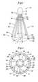
- FIG. 1is a perspective view of a retrievable blood clot filter device 10 in accordance with an illustrative embodiment of the present invention.
- Blood clot filter device 10includes an apical head 12 , and a plurality of elongated filter legs 14 each having a joined end section 16 and a free end section 18 .
- Each of the filter legs 14may be configured identically with respect to each other, and may be symmetrically spaced about a central longitudinal axis L in a generally conical-shaped configuration when expanded.
- the filter legs 14may be collectively arranged about the longitudinal axis L such that the joined end section 16 of each filter leg 14 converges at the apical head 12 to form an apex.
- the filter legs 14may be biased to expand from a substantially straight position when radially constrained within a delivery device to an outswept position when deployed in a blood vessel.
- Each filter leg 14may include a support member 20 having a first end 22 that is coupled to the apical head 12 , and a distal end 24 that extends angularly in an outswept manner to a retractable anchoring member 26 disposed on the free end section 18 of each filter leg 14 .
- the support member 20may comprise a length of wire, rod, tubing, or other suitable member that can be formed into the shape depicted generally in FIG. 1 .
- a suitable metal or metal alloysuch as platinum, gold, tantalum, tungsten, titanium, or stainless steel may be used.
- Metal or metal-polymer composites containing one or more of these materialsmay also be used in forming the support members 20 , if desired.
- the support members 20can be formed from a superelastic material such as a nickel-titanium alloy (Nitinol). Such materials are capable of enduring significant bending without forming residual stresses within the material, allowing the support members 20 to be collapsed into relatively small delivery devices. The ability of the support members 20 to spring back to their original, unstressed state is significant to permit the blood clot filter device 10 to expand to a desired shape when deployed within a blood vessel.
- the anchoring members 26can be formed integral with or as separate elements from the wire, rod, tubing, etc. forming the support members 20 .
- the anchoring members 26are formed as extensions of the material forming the support members 20 .
- the anchoring members 26may comprise separate members that have been attached to the distal end 24 of the support member 20 by adhesive, laser welding, brazing or other suitable method.
- a pointed tip portion 28 of each anchoring member 26can be configured to pierce the vessel wall.
- the pointed tip portion 28may be formed, for example, by grinding down a portion of the wire forming the distal end 24 of each support member 20 to form a point. While a pointed structure is specifically illustrated for anchoring members 26 of FIG. 1 , it should be understood that other suitable means for securing the blood clot filter device 10 to the vessel wall could be employed.
- the anchoring member 26could include a needle, hook, barb prong, wedge, or other suitable attachment member known in the art.
- each filter tube 30can include a first end 32 , a second end 34 , and an inner lumen 36 configured to slidably receive a corresponding one of the support members 20 therein.
- the first end 32 of each filter tube 30may be attached to or formed integrally with an annular-shaped hub 38 that extends circumferentially about the filter legs 14 adjacent to the apical head 12 .
- the second end 34 of each tubular member 30in turn, can be configured to lie adjacent to the anchoring member 26 at or near the distal end 24 of the support member 20 .
- the filter tubes 30can have a substantially straight shape along their length, as shown in FIG. 1 , or can assume some other desired shape.
- a small bend or kink 40 located at or near the free end section 18 of the filter legs 14can be provided to orient a portion of the filter legs 14 in a direction substantially parallel to the inner wall of the blood vessel.
- the filter tubes 30can be formed of one or more segments of sheathing or tubing having a metal, metal alloy, or metal-polymer composition.
- suitable materialsinclude stainless steel, platinum, tungsten, nickel-titanium alloy, polyethylene terapthalate (PET), polytetraflouroethylene (PTFE), polyurethane (nylon) fluorinated ethylene propylene (FEP), polyurethane, polypropylene (PP), polyvinylchloride (PVC), polyether-ester, polyester, polyamide, elastomeric polyamides, block polyamide/ethers, polyether block amide (PEBA), silicones, polyethylene, polyether-ether ketone (PEEK), polyimide (PI), and polyetherimide (PEI).
- the inner lumen 36 of each filter tube 30may also include a lubricious coating such as a layer of polytetraflouroethylene (PTFE) to reduce friction between the contact surfaces of the filter tube 30 and support member 20 .
- the filter tubes 30provide a surface upon which blood clots (emboli) can be collected.
- all or a portion of the filter tubes 30may include an anti-thrombogenic coating such as herapin (or its derivatives), urokinase, or PPack (dextrophenylalanine proline arginine chloromethylketone).
- An anti-inflammatory agentsuch as dexamethasone, prednisolone, corticosterone, budesonide, estrogen, sulfasalazine, mesalamine, or any suitable combination or mixture thereof may also be applied to the filter tubes 30 as well as other locations of the blood clot filter device 10 to prevent inflammation caused by the engagement of the device 10 along the vessel wall.
- FIG. 2is a top perspective view showing the blood clot filter device 10 of FIG. 1 implanted within a blood vessel V.
- the filter legs 14are configured to extend outwardly from the apical head 12 during deployment to anchor the blood clot filter device 10 along the inner wall W of the blood vessel V.
- the filter legs 14can be arranged at equidistant intervals such that the filter legs 14 are symmetrically spaced about the longitudinal axis formed by the apical head 12 .
- the blood clot filter device 10is shown having six filter legs 14 arranged at 60° intervals. It is to be understood, however, that any number or arrangement of filter legs can be employed in accordance with the present invention.
- each anchoring member 26When expanded within the blood vessel V, the pointed tip portion 28 of each anchoring member 26 can be configured to pierce the inner wall of the vessel V. In use, each anchoring member 26 compresses against the inner wall W of the vessel V as a result of the outwardly directed force exerted by the filter legs 14 . The amount of force exerted against the inner wall W can be sufficient to prevent migration of the blood clot filter device 10 within the vessel V. By changing design factors such as the dimensions and material composition of the various filter components, the blood clot filter device 10 can be placed in a wide range of vessels within the body.
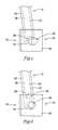
- FIG. 3is an enlarged view of the free end section 18 of one of the filter legs 14 , showing the anchoring member 26 in a deployed position.
- a bending region 42 of the support member 20orients the anchoring member 26 at an angle ⁇ relative to the support member 20 , directing the pointed tip portion 28 towards the inner wall of the blood vessel.
- the anchoring member 26can be oriented at any angle ⁇ relative to the support member 20 by applying a bending force thereto.
- the anchoring members 26can then be bent to a desired angle ⁇ to orient the pointed tip portions 28 in a direction towards the inner wall of the blood vessel.
- the anchoring members 26can be bent at the bend region 42 to orient the pointed tip portions 28 at an angle substantially perpendicular to the vessel wall W.
- the bending region 42can be configured to orient the pointed tip portions 28 at an acute or obtuse angle relative to the vessel wall W.
- FIG. 4is an enlarged view showing the anchoring member 26 of FIG. 3 in a retracted position.
- the anchoring member 26can be configured to retract into the inner lumen 36 of the filter tube 30 .
- Retraction of the anchoring member 26 into the inner lumen 36can be accomplished by either advancing the filter tube 30 over the anchoring member 26 while holding the anchoring member 26 stationary, or by advancing of the support member 20 towards the apex of the blood clot filter device 10 while holding the filter tube 30 stationary.
- the force of the filter tube 30 exerted on the anchoring member 26forces the bending region 42 to bend, causing the anchoring member 26 to align with the support member 20 .
- the amount of force required to bend the anchoring member 26will typically be greater than the force exerted on the blood clot filter device 10 by the flow of blood within the blood vessel. This prevents the anchoring members 26 from prematurely bending within the blood vessel as a result of spikes in blood pressure, or as a result of incidental shifts or movement of the blood clot filter device 10 within the blood vessel.
- the amount of force required to bend the anchoring members 26can be varied based on a number of factors including, for example, the type of material(s) used to construct the blood clot filter device 10 , and the dimensions of the various components employed.
- the bending region 42can be reduced in profile or include a notch that reduces the stiffness at this region.
- the anchoring member 26may be formed from a flexible material such as Beta III Titanium or a nickel-titanium alloy that can be easily bent without permanently deforming the material.
- FIG. 5is an enlarged view showing an alternative anchoring arrangement using a landing pad 44 .
- the landing pad 44can be attached to the distal end 34 of the filter tube 30 .
- the landing pad 44may be attached to the filter tube 30 at an angle to permit a flat face 46 of the landing pad 44 to lie parallel to and flush with the inner wall of the blood vessel. While a rectangular shaped landing pad 44 is depicted in the illustrative embodiment of FIG. 5 , it should be understood that the landing pad 44 could assume any number of desirable shaped.
- the landing padmay have a oval or circular shape with a convex face that approximates the curve of the vessel wall. In use, the landing pad 44 reduces trauma to the body by distributing the force exerted on the wall of the blood vessel by the filter tube 30 over a greater area.
- FIG. 6is an enlarged view showing the anchoring member 26 of FIG. 5 in a retracted position.
- an opening 48 originating on the flat face 46 and extending through the thickness of the landing pad 44can be configured to receive the anchoring member 26 therethrough, allowing the anchoring member 26 to be retracted into the inner lumen 36 of the filter tube 30 .
- Retraction of the anchoring member 26 into the inner lumen 36 of the filter tube 30can be accomplished by advancing of the support member 20 in a direction towards the apex of the blood clot filter device 10 while holding the filter tube 30 and attached landing pad 44 stationary.
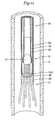
- FIG. 7is a perspective view showing a retrievable blood clot filter device 50 in accordance another illustrative embodiment of the present invention.
- blood clot filter device 50includes an apical head 52 , and a plurality of elongated filter legs 54 each having a joined end section 56 and a free end section 58 .
- Each of the filter legs 54may include a support member 60 having a first end 62 coupled to the apical head 52 , and a second end 64 that extends in an outswept manner to a retractable anchoring member 66 disposed on the free end section 58 of the filter leg 54 .
- the support members 60can be slidably received within several coiled filter tubes 66 .
- the filter tubes 66may each comprise a length or segment of coil tubing having a first end 68 , a second end 70 , and an inner lumen 72 configured to slidably receive a corresponding one of the support members 60 therein.
- the first end 68 of each coiled filter tube 66can be attached to or formed integrally with an annular-shaped hub 74 that extends circumferentially about the coiled filter legs 54 adjacent to the apical head 52 .
- the second end 70 of each coiled filter tube 66in turn, can be configured to lie adjacent to the anchoring member 60 .
- the coils forming the coiled filter tubes 66can be tightly spaced together to eliminate any spacing between adjacent coil turns. Alternatively, the coils forming the coiled filter tubes 66 can be loosely spaced, forming several gaps between adjacent coil turns.
- Each of the coiled filter tubes 66can be formed by wrapping a wire about a mandrel having an outer diameter slightly larger than the outer diameter of the support members 60 to permit the support members 60 to slide therein.
- the inner lumen 72 of each filter tube 66may also include a lubricious coating such as a layer of polytetraflouroethylene (PTFE) to reduce friction between the contacts surfaces of the filter tube 66 and support member 60 .
- PTFEpolytetraflouroethylene
- FIG. 8is a partially broken, longitudinal cross-sectional view showing a suitable retrieval apparatus 76 for use in retrieving a medical device such as the blood clot filter device 10 described herein.
- the retrieval apparatus 76may comprise a plurality of separate tubular members that can be inserted percutaneously into the body and advanced through the vasculature to the site of the implanted blood clot filter.
- the retrieval apparatus 76can include an inner tubular member 78 , a middle tubular member 80 slidably disposed about the inner tubular member 78 , and an outer sheath 82 slidably disposed about the middle tubular member 78 .
- the arrangement of the various members 78 , 80 , 82can differ, however, depending on the particular filter device being retrieved.
- Each of the tubular members 78 , 80 , 82may extend from a proximal end 84 of the retrieval apparatus 76 that can be manipulated from a position outside of the patient's body, to a distal end 86 thereof that can be inserted into the body and advanced to the implantation site to retrieve the blood clot filter from within the blood vessel.
- a hub 88 disposed at or near the proximal end 84 of the retrieval apparatus 76can be employed to fix the relative positioning of the tubular members 78 , 80 , 82 during the retrieval process.
- the inner tubular member 78can be configured to grasp the apical head 12 of the blood clot filter device 10 , allowing the clinician to retract the anchoring members 26 and collapse the filter legs 14 using, respectively, the middle tubular member 80 and outer sheath 82 .
- a proximal segment 90 of the inner tubular member 78may be formed from a suitable stiff material having sufficient column strength and rigidity to withstand buckling or bulging as the inner tubular member 78 is engaged against the apical head 12 .
- the wall thickness of the proximal segment 90may be generally uniform along the length of the inner tubular member 78 , or may vary to alter the stiffness or torqueability characteristics of the inner tubular member 78 , as desired. In the illustrative embodiment of FIG.
- the proximal segment 90may decrease in thickness from the proximal end of the inner tubular member (not shown) towards the distal end 92 of the proximal segment 90 , wherein the proximal segment 90 transitions into a flexible distal segment 94 . It should be understood, however, that the proximal segment 90 may have a constant thickness along its length, or may assume some other desired configuration.
- the proximal segment 90may be formed at least in part from a polymeric material such as polyether block amide (PEBA), which is commercially available from Atochem Polymers of Birdsboro, Pa. under the trade name PEBAX. Other suitable polymeric materials frequently used in the construction of catheters shafts and/or retrieval sheaths may also be employed.
- PEBApolyether block amide
- the proximal segment 90may comprise one or more segments having differing material characteristics such as stiffness, torsional rigidity, tensile strength, and/or hardness, if desired.
- the distal segment 94 of the inner tubular member 78can be configured to radially expand when compressed in a direction along its length, allowing the inner tubular member 78 to grasp the apical head 12 .
- the expandability of the distal segment 94may be due at least in part to the selection of materials used to form the segment 94 .
- Examples of materials that can be used in the construction of the distal segment 94may include, but are not limited to, polyethylene terapthalate (PET), polytetrafluoroethylene (PTFE), polyurethane (Nylon) fluorinated ethylene propylene (FEP), ethylene tetrafluoroethylene (ETFE), polyurethane, polypropylene (PP), polyvinylchloride (PVC), polyether-ester, polyester, polyamide, elastomeric polyamides, block polyamide/ethers, polyether block amide (PEBA), silicones, polyethylene (PE), polyether-ether ketone (PEEK), polyimide (PI), polyetherimide (PEI), polyphenylene sulfide (PPS), polyphenylene oxide (PPO), polysulfone, perfluoro(propyl vinyl ether) (PFA), or other suitable materials, mixtures, combinations or copolymers thereof.
- the polymeric materialmay be blended with or otherwise include a
- the material forming the proximal segment 90 and/or distal segment 94may include a radiopaque filler such as barium sulfate (BaSO 4 ) or bismuth subcarbonate ((BiO) 2 CO 3 ) to permit visualization of the retrieval apparatus 76 within the body.
- Radiopaque materialsare understood to be materials capable of producing a relatively bright image on a fluoroscopic monitor or other imaging device. When a radiopaque die is injected into the vessel at issue, the relatively bright image produced on the monitor can be used to determine the location of the inner tubular member 78 within the body.
- a braided layer 96 coupled to or formed integrally with the distal segment 94 of the inner tubular member 78can be utilized to impart expandability to the distal segment 94 while maintaining its desired stiffness and rigidity characteristics.
- the braided layer 96may include a number of filaments 98 encased within or disposed adjacent to the distal segment 94 .
- the filaments 98may be arranged generally in two sets of parallel helices wound in opposite directions about a common longitudinal axis disposed through the center of the inner tubular member 78 .
- the filaments 98may intersect each other in an overlapping or interwoven fashion to permit the distal segment 94 to radially expand when subjected to a compressive force.
- the braided layer 96extends along the entire length of the distal segment 94 , terminating proximally at or near the distal end 92 of the proximal segment 90 . In other embodiments, however, the braided layer 96 may extend along only a portion of the distal segment 94 , or may extend further into all or a portion of the proximal segment 90 .
- the filaments 96can be formed from any number of suitable materials including polymers, metals, metal alloys, metal-polymer composites, or metal-metal composites. Some examples of suitable metals and metal alloys include platinum, stainless steel, Beta III Titanium, nickel-titanium alloy (Nitinol), nickel-chromium alloy, nickel-chromium alloy, cobalt alloy, or the like. Polymers similar to that used in the construction of the proximal and distal segments 90 , 94 may also be used in forming the filaments 98 .
- the filaments 98 , or portions thereof,may also be doped with or otherwise include a radiopaque material to facilitate fluoroscopic visualization within the body.
- the filaments 98may be formed at least in part of gold, platinum, palladium, tantalum, tungsten alloy or other suitable radiopaque material capable of producing a relatively bright image on a fluoroscopic screen or other imaging device.
- the middle tubular member 80can be configured to engage the annular-shaped hub 38 and retract the anchoring members 26 into the filter tubes 30 .
- the middle tubular member 80may comprise a rigid sheath or tube that extends from a proximal end (not shown) to a distal end 100 thereof.
- An annular spaced gap 102 disposed between the inner tubular member 78 and middle tubular member 80provides a sufficient amount of clearance to permit the middle tubular member 80 to be advanced beyond the apical head 12 and against the hub 38 once the distal segment 94 of the inner tubular member 78 has been expanded to grasp the apical head 12 .
- the retrieval apparatus 76may further include an outer sheath 82 that can be used in collapsing and retrieving the blood clot filter device 10 within the body.
- the outer sheath 82may comprise an elongated segment of sheathing or hypodermic tubing having an internal lumen dimensioned to receive the collapsed blood clot filter device 10 therein.
- the outer sheath 82may comprise the same or similar sheath used to deliver the blood clot filter device 10 to the target (i.e. implantation) site.
- the blood clot filter device 10can be loaded into an introducer sheath and inserted percutaneously into the body in accordance with standard practice in the art.
- the blood clot filter device 10is then advanced to a desired vessel within the body (e.g. the inferior vena cava), and removed from within the introducer sheath, causing the filter legs 14 to deploy and engage the wall of the vessel.
- a desired vessel within the bodye.g. the inferior vena cava
- the pointed tip portion 28 on the anchoring member 26pierces the cava wall W, temporarily fixing the blood clot filter device within the vessel V, as shown, for example, in FIG. 9 .
- blood flow within the blood vessel(indicated generally by the upwardly directed arrow) can be collected on the exposed surfaces of the apical head 12 and filter legs 14 .
- the retrieval apparatus 76can be inserted percutaneously into the vasculature and advanced to a position adjacent to the blood clot filter device 10 .
- the retrieval apparatus 76is shown inserted via a jugular approach through the jugular vein of the patient.
- the cliniciannext releases the hub 88 (not shown) and advances the inner tubular member 78 distally within the blood vessel V toward the apical head 12 .
- the inner tubular member 78is shown engaged against the apical head 12 , causing the distal segment 94 of the inner tubular member 78 to expand and grasp the apical head 12 .
- the middle tubular member 80is further shown advanced distally toward the blood clot filter device 10 , with the distal end 100 thereof seated against the hub 38 .
- the clinicianTo retract the anchoring members 26 from the vessel wall, the clinician, while holding the blood clot filter device 10 stationary with the middle tubular member 80 , retracts the inner tubular member 78 in a proximal direction. Alternatively, the clinician may hold the inner tubular member 78 stationary while advancing the distal end 100 of the middle tubular member 80 against the hub 38 . In either case, the movement of the filter tubes 30 about the support members 20 causes the anchoring members 26 to bend and retract into the filter tubes 30 , as shown, for example, in FIG. 11 .
- the cliniciancan next advance the outer sheath 82 distally about the filter legs 14 , causing the filter legs 14 to begin to collapse, as shown, for example, in FIG. 12 .
- the blood clot filter device 10assume a fully collapsed position, as shown, for example, in FIG. 13 , allowing the clinician to either remove the blood clot filter device 10 from the body, or reposition the device 10 at another location within the blood vessel V
- FIG. 14is a perspective view of a retrievable blood clot filter device 104 in accordance with another illustrative embodiment of the present invention.
- the blood clot filter device 104can include an apical head 106 , and a plurality of elongated filter legs 108 each having a joined end section 110 and a free end section 112 .
- Each of the filter legs 108can include a support member 114 having a first end 116 coupled to the apical head 106 , and a second end 118 that extends angularly in an outswept manner to a retractable anchoring member 120 disposed on the free end section 112 of each filter leg 108 .
- the support members 114can be slidably received within several filter tubes 122 each having a first end 124 , a second end 126 , and an inner lumen 128 therein.
- the first end 124 of each filter tube 122can be attached to or formed integrally with an annular-shaped hub 130 that extends circumferentially about the filter legs 108 adjacent to the apical head 106 .
- annular-shaped hub 130that extends circumferentially about the filter legs 108 adjacent to the apical head 106 .
- the hub 130includes a series of notches or slots 132 formed within the interior 134 of the hub 130 , which as discussed in greater detail below, can be used in conjunction with a retrieval apparatus to retrieve the blood clot filter device 104 within a Vena Cava via a femoral approach through one of the femoral veins.
- Several openings 136 (hidden) disposed through the thickness of the hub 130can be configured to slidably receive the support members 114 .
- FIG. 15is a partially broken, longitudinal cross-sectional view showing a retrieval apparatus 138 for use in retrieving a medical device such as blood clot filter 104 discussed herein.
- retrieval apparatus 138may include several members that extend from a proximal end 140 of the retrieval apparatus 138 that can be manipulated from a position outside of the patient's body, to a distal end 142 thereof that can be inserted into the body and advanced to the implantation site.
- a proximal end 140 of the retrieval apparatus 138that can be manipulated from a position outside of the patient's body, to a distal end 142 thereof that can be inserted into the body and advanced to the implantation site.
- the retrieval apparatus 138may include an inner member 144 , a middle tubular member 146 slidably disposed about the inner member 144 , and an outer sheath 146 slidably disposed about the middle tubular member 146 .
- a hub 150 disposed at or near the proximal end 104 of the retrieval apparatus 138can be employed to fix the relative positioning of the members 144 , 146 , 148 during the retrieval process.
- the inner member 144may include a rod or tubing that can be utilized to engage the apical head 106 of the blood clot filter device 104 .
- the inner member 144can be dimensioned to allow the inner member 144 to be inserted via a femoral approach through the interior 134 of the hub 130 towards the rear of the apical head 106 .
- a bulbous-shaped tip 152 disposed on the distal end of the inner member 144can be configured to engage the apical head 106 .
- the middle tubular member 146may include a suitably rigid tubular member having one or more fins 154 dimensioned to fit within the notches or slots 132 formed within the interior 134 of the hub 130 .
- the one or more fins 154 on the middle tubular member 146can be inserted through the interior 134 of the hub 130 in a direction toward the apical head 106 .
- the middle tubular member 146can then be rotated slightly (e.g. 90° clockwise or counterclockwise) causing the one or more fins 154 to become misaligned with the notches or slots 130 .
- the outer sheath 148can be utilized to collapse and retrieve the blood clot filter device 104 , allowing the clinician to either remove or reposition the device 104 within the body.
- the outer tubular member 148may comprise a sheath or hypodermic having an internal lumen dimensioned to collapse and receive the blood clot filter device 104 therein.
- the outer tubular member 148may comprise the same or similar sheath used to deliver the blood clot filter device 104 to the target (i.e. implantation) site.
- FIGS. 16-20an illustrative method of retrieving the blood clot filter device 104 of FIG. 14 using the retrieval apparatus of FIG. 15 will now be described.
- the retrieval apparatus 104is shown advanced via a femoral approach into a blood vessel V (e.g. the inferior vena cava) adjacent the blood clot filter device 104 .
- Ve.g. the inferior vena cava
- the cliniciannext advances the inner member 144 distally towards the apical head 106 of the blood clot filter device 104 .
- the inner member 144is shown advanced to the apical head 106 , causing the bulbous tip 152 to engage the apical head 106 .
- the clinicianmay next advance the middle tubular member 146 distally towards the blood clot filter 104 to engage the hub 130 .
- the clinicianpushes the middle tubular member 146 through the interior 134 of the hub 130 until the one or more fins 154 are disposed beyond the notches or slots 132 .
- the middle tubular member 144can then be rotated slightly, causing the one or more fins 154 to become misaligned with the notches or slots 132 , as shown, for example, in FIG. 18 .
- the clinicianTo retract the anchoring members 120 within the filter tubes 122 , the clinician, while holding the hub 130 stationary with middle tubular member 146 , advances the apical head 106 in an upward direction by pushing the inner member 144 distally within the blood vessel V. The advancement of the apical head 106 in this manner causes the anchoring members 120 to bend and retract into the filter tubes 122 , as shown, for example, in FIG. 19 . Continued advancement of the apical head 104 in this direction causes the filter legs 108 to begin to collapse inwardly, allowing the outer sheath 148 of the retrieval apparatus 138 to be advanced over the filter legs 108 encapsulate the blood clot filter 104 therein, as shown, for example, in FIG. 20 . The retrieval apparatus 138 and accompanying blood clot filter device 104 can then be removed from the body, or repositioned at another location within the vessel and redeployed.
Landscapes
- Health & Medical Sciences (AREA)
- Cardiology (AREA)
- Oral & Maxillofacial Surgery (AREA)
- Transplantation (AREA)
- Engineering & Computer Science (AREA)
- Biomedical Technology (AREA)
- Heart & Thoracic Surgery (AREA)
- Vascular Medicine (AREA)
- Life Sciences & Earth Sciences (AREA)
- Animal Behavior & Ethology (AREA)
- General Health & Medical Sciences (AREA)
- Public Health (AREA)
- Veterinary Medicine (AREA)
- Surgical Instruments (AREA)
- External Artificial Organs (AREA)
Abstract
Description
Claims (22)
Priority Applications (8)
| Application Number | Priority Date | Filing Date | Title |
|---|---|---|---|
| US10/762,643US8231649B2 (en) | 2004-01-20 | 2004-01-20 | Retrievable blood clot filter with retractable anchoring members |
| EP05705892AEP1706062B1 (en) | 2004-01-20 | 2005-01-18 | Retrievable blood clot filter with retractable anchoring members |
| JP2006551229AJP4696080B2 (en) | 2004-01-20 | 2005-01-18 | Retrievable thrombus filter device with retractable fixation member |
| PCT/US2005/001661WO2005072648A1 (en) | 2004-01-20 | 2005-01-18 | Retrievable blood clot filter with retractable anchoring members |
| DE602005024914TDE602005024914D1 (en) | 2004-01-20 | 2005-01-18 | REMOVABLE BLOOD CLEANER FILTER WITH REFERENCE FIXING HOOK |
| CA002553981ACA2553981A1 (en) | 2004-01-20 | 2005-01-18 | Retrievable blood clot filter with retractable anchoring members |
| AT05705892TATE489053T1 (en) | 2004-01-20 | 2005-01-18 | REMOVABLE BLOOD CLOT FILTER WITH RETRACTABLE ATTACHMENT HOOKS |
| US13/537,154US20120265239A1 (en) | 2004-01-20 | 2012-06-29 | Retrievable blood clot filter with retractable anchoring members |
Applications Claiming Priority (1)
| Application Number | Priority Date | Filing Date | Title |
|---|---|---|---|
| US10/762,643US8231649B2 (en) | 2004-01-20 | 2004-01-20 | Retrievable blood clot filter with retractable anchoring members |
Related Child Applications (1)
| Application Number | Title | Priority Date | Filing Date |
|---|---|---|---|
| US13/537,154ContinuationUS20120265239A1 (en) | 2004-01-20 | 2012-06-29 | Retrievable blood clot filter with retractable anchoring members |
Publications (2)
| Publication Number | Publication Date |
|---|---|
| US20050159771A1 US20050159771A1 (en) | 2005-07-21 |
| US8231649B2true US8231649B2 (en) | 2012-07-31 |
Family
ID=34750361
Family Applications (2)
| Application Number | Title | Priority Date | Filing Date |
|---|---|---|---|
| US10/762,643Expired - Fee RelatedUS8231649B2 (en) | 2004-01-20 | 2004-01-20 | Retrievable blood clot filter with retractable anchoring members |
| US13/537,154AbandonedUS20120265239A1 (en) | 2004-01-20 | 2012-06-29 | Retrievable blood clot filter with retractable anchoring members |
Family Applications After (1)
| Application Number | Title | Priority Date | Filing Date |
|---|---|---|---|
| US13/537,154AbandonedUS20120265239A1 (en) | 2004-01-20 | 2012-06-29 | Retrievable blood clot filter with retractable anchoring members |
Country Status (7)
| Country | Link |
|---|---|
| US (2) | US8231649B2 (en) |
| EP (1) | EP1706062B1 (en) |
| JP (1) | JP4696080B2 (en) |
| AT (1) | ATE489053T1 (en) |
| CA (1) | CA2553981A1 (en) |
| DE (1) | DE602005024914D1 (en) |
| WO (1) | WO2005072648A1 (en) |
Cited By (3)
| Publication number | Priority date | Publication date | Assignee | Title |
|---|---|---|---|---|
| US9308074B2 (en) | 2012-12-04 | 2016-04-12 | Cook Medical Technologies Llc | Filter retrieval device |
| US10010398B2 (en) | 2013-10-01 | 2018-07-03 | Cook Medical Technologies Llc | Filter device, system, and method |
| US10117736B2 (en) | 2014-08-06 | 2018-11-06 | Cook Medical Technologies Llc | Low radial force filter |
Families Citing this family (70)
| Publication number | Priority date | Publication date | Assignee | Title |
|---|---|---|---|---|
| US7314477B1 (en) | 1998-09-25 | 2008-01-01 | C.R. Bard Inc. | Removable embolus blood clot filter and filter delivery unit |
| US6267776B1 (en)* | 1999-05-03 | 2001-07-31 | O'connell Paul T. | Vena cava filter and method for treating pulmonary embolism |
| US9204956B2 (en) | 2002-02-20 | 2015-12-08 | C. R. Bard, Inc. | IVC filter with translating hooks |
| US7704267B2 (en) | 2004-08-04 | 2010-04-27 | C. R. Bard, Inc. | Non-entangling vena cava filter |
| US7794473B2 (en) | 2004-11-12 | 2010-09-14 | C.R. Bard, Inc. | Filter delivery system |
| US8267954B2 (en) | 2005-02-04 | 2012-09-18 | C. R. Bard, Inc. | Vascular filter with sensing capability |
| US7993362B2 (en)* | 2005-02-16 | 2011-08-09 | Boston Scientific Scimed, Inc. | Filter with positioning and retrieval devices and methods |
| WO2006107939A1 (en)* | 2005-04-04 | 2006-10-12 | B. Braun Medical Sas | Removable filter head |
| CA2607580C (en) | 2005-05-12 | 2016-12-20 | C.R. Bard Inc. | Removable embolus blood clot filter |
| US12115057B2 (en) | 2005-05-12 | 2024-10-15 | C.R. Bard, Inc. | Tubular filter |
| US8613754B2 (en) | 2005-05-12 | 2013-12-24 | C. R. Bard, Inc. | Tubular filter |
| WO2007021340A1 (en) | 2005-08-09 | 2007-02-22 | C.R. Bard Inc | Embolus blood clot filter and delivery system |
| US9131999B2 (en) | 2005-11-18 | 2015-09-15 | C.R. Bard Inc. | Vena cava filter with filament |
| CA2630447A1 (en)* | 2005-12-02 | 2007-06-07 | C.R. Bard, Inc. | Helical vena cava filter |
| US8562638B2 (en)* | 2005-12-30 | 2013-10-22 | C.R. Bard, Inc. | Embolus blood clot filter with floating filter basket |
| WO2007079407A2 (en)* | 2005-12-30 | 2007-07-12 | C.R. Bard Inc. | Embolus blood clot filter with post delivery actuation |
| WO2007079410A2 (en) | 2005-12-30 | 2007-07-12 | C.R Bard Inc. | Embolus blood clot filter delivery system |
| US9730781B2 (en) | 2005-12-30 | 2017-08-15 | C. R. Bard, Inc. | Embolus blood clot filter removal system and method |
| US8317818B2 (en)* | 2005-12-30 | 2012-11-27 | C.R. Bard, Inc. | Removable blood clot filter with edge for cutting through the endothelium |
| WO2007099448A2 (en)* | 2006-03-03 | 2007-09-07 | Vayro Ltd. | A fastening device |
| WO2007133366A2 (en) | 2006-05-02 | 2007-11-22 | C. R. Bard, Inc. | Vena cava filter formed from a sheet |
| US9326842B2 (en) | 2006-06-05 | 2016-05-03 | C. R . Bard, Inc. | Embolus blood clot filter utilizable with a single delivery system or a single retrieval system in one of a femoral or jugular access |
| US20080119867A1 (en)* | 2006-10-31 | 2008-05-22 | Cook Incorporated | Puncture and abrasion resistant sheath |
| US8961557B2 (en) | 2007-01-31 | 2015-02-24 | Stanley Batiste | Intravenous filter with fluid or medication infusion capability |
| US8795351B2 (en) | 2007-04-13 | 2014-08-05 | C.R. Bard, Inc. | Migration resistant embolic filter |
| US20080294189A1 (en)* | 2007-05-23 | 2008-11-27 | Moll Fransiscus L | Vein filter |
| US20090005803A1 (en)* | 2007-06-27 | 2009-01-01 | Stanley Batiste | Removable vascular filter and method of filter use |
| US8246648B2 (en) | 2008-11-10 | 2012-08-21 | Cook Medical Technologies Llc | Removable vena cava filter with improved leg |
| WO2011043900A1 (en)* | 2009-10-08 | 2011-04-14 | Cook Incorporated | Vascular implant retrieval assembly and tool for the same |
| EP2523629B1 (en)* | 2010-01-12 | 2021-04-14 | Cook Medical Technologies LLC | Visual stabilizer on anchor legs of vena cava filter |
| JP5998147B2 (en)* | 2011-09-27 | 2016-09-28 | 寛治 井上 | Vascular free substance capture device |
| US8702747B2 (en) | 2011-10-21 | 2014-04-22 | Cook Medical Technologies Llc | Femoral removal vena cava filter |
| US20150142025A1 (en) | 2012-06-26 | 2015-05-21 | V.V.T. Med Ltd. | Biodegradable blood vessel occlusion and narrowing |
| DK2863811T3 (en)* | 2012-06-26 | 2017-12-11 | Vvt Medical Ltd | BLOOD VESSEL CONCLUSION DEVICES |
| US9308073B2 (en) | 2012-09-12 | 2016-04-12 | Cook Medical Technologies Llc | Vena cava filter with dual retrieval |
| US9833305B2 (en) | 2012-09-12 | 2017-12-05 | Cook Medical Technologies Llc | Vena cava filter with dual retrieval |
| US9414752B2 (en) | 2012-11-09 | 2016-08-16 | Elwha Llc | Embolism deflector |
| US10307240B2 (en)* | 2012-12-11 | 2019-06-04 | Alan Zajarias | Methods and apparatus for capturing embolic debris during endovascular procedures |
| US20180360586A9 (en)* | 2013-03-07 | 2018-12-20 | Merit Medical Systems, Inc. | Embolic filter balloon |
| US11154302B2 (en)* | 2014-03-31 | 2021-10-26 | DePuy Synthes Products, Inc. | Aneurysm occlusion device |
| US11076860B2 (en) | 2014-03-31 | 2021-08-03 | DePuy Synthes Products, Inc. | Aneurysm occlusion device |
| GB2527761A (en)* | 2014-06-30 | 2016-01-06 | Cook Medical Technologies Llc | Improved vascular filter and anchoring arrangement therefor |
| US10245072B2 (en) | 2015-07-10 | 2019-04-02 | Medtronic, Inc. | Extravascular medical access tools having boring tip and methods of using such tools |
| US10758729B2 (en)* | 2015-10-01 | 2020-09-01 | Medtronic, Inc. | Interventional medical systems, catheters, and methods |
| US10080888B2 (en) | 2015-11-16 | 2018-09-25 | Medtronic, Inc. | Interventional medical systems and associated methods |
| CN108143517B (en)* | 2016-12-06 | 2024-07-05 | 先健科技(深圳)有限公司 | Filter device |
| CN110545739A (en) | 2017-02-23 | 2019-12-06 | 德普伊新特斯产品公司 | aneurysm devices and delivery systems |
| US10905430B2 (en) | 2018-01-24 | 2021-02-02 | DePuy Synthes Products, Inc. | Aneurysm device and delivery system |
| US11058430B2 (en) | 2018-05-25 | 2021-07-13 | DePuy Synthes Products, Inc. | Aneurysm device and delivery system |
| US11596412B2 (en) | 2018-05-25 | 2023-03-07 | DePuy Synthes Products, Inc. | Aneurysm device and delivery system |
| US10939915B2 (en) | 2018-05-31 | 2021-03-09 | DePuy Synthes Products, Inc. | Aneurysm device and delivery system |
| US11051825B2 (en) | 2018-08-08 | 2021-07-06 | DePuy Synthes Products, Inc. | Delivery system for embolic braid |
| US11123077B2 (en) | 2018-09-25 | 2021-09-21 | DePuy Synthes Products, Inc. | Intrasaccular device positioning and deployment system |
| CN109199632B (en)* | 2018-09-26 | 2024-02-20 | 李雷 | Inferior vena cava embolic filter |
| US11076861B2 (en) | 2018-10-12 | 2021-08-03 | DePuy Synthes Products, Inc. | Folded aneurysm treatment device and delivery method |
| US11406392B2 (en) | 2018-12-12 | 2022-08-09 | DePuy Synthes Products, Inc. | Aneurysm occluding device for use with coagulating agents |
| US11272939B2 (en) | 2018-12-18 | 2022-03-15 | DePuy Synthes Products, Inc. | Intrasaccular flow diverter for treating cerebral aneurysms |
| US11134953B2 (en) | 2019-02-06 | 2021-10-05 | DePuy Synthes Products, Inc. | Adhesive cover occluding device for aneurysm treatment |
| US11337706B2 (en) | 2019-03-27 | 2022-05-24 | DePuy Synthes Products, Inc. | Aneurysm treatment device |
| US11672542B2 (en) | 2019-05-21 | 2023-06-13 | DePuy Synthes Products, Inc. | Aneurysm treatment with pushable ball segment |
| US10653425B1 (en) | 2019-05-21 | 2020-05-19 | DePuy Synthes Products, Inc. | Layered braided aneurysm treatment device |
| US11607226B2 (en) | 2019-05-21 | 2023-03-21 | DePuy Synthes Products, Inc. | Layered braided aneurysm treatment device with corrugations |
| US11413046B2 (en) | 2019-05-21 | 2022-08-16 | DePuy Synthes Products, Inc. | Layered braided aneurysm treatment device |
| US11497504B2 (en) | 2019-05-21 | 2022-11-15 | DePuy Synthes Products, Inc. | Aneurysm treatment with pushable implanted braid |
| US11602350B2 (en) | 2019-12-05 | 2023-03-14 | DePuy Synthes Products, Inc. | Intrasaccular inverting braid with highly flexible fill material |
| US11278292B2 (en) | 2019-05-21 | 2022-03-22 | DePuy Synthes Products, Inc. | Inverting braided aneurysm treatment system and method |
| US11457926B2 (en) | 2019-12-18 | 2022-10-04 | DePuy Synthes Products, Inc. | Implant having an intrasaccular section and intravascular section |
| JP7252181B2 (en)* | 2020-08-26 | 2023-04-04 | シー・アール・バード・インコーポレーテッド | Interventional medical device with reduced breakage risk |
| CN115607331B (en)* | 2022-12-16 | 2023-03-31 | 北京心祐医疗科技有限公司 | Adjustable anchoring type vena cava filter |
| CN115607330B (en)* | 2022-12-16 | 2023-03-21 | 北京心祐医疗科技有限公司 | Vena cava filter |
Citations (43)
| Publication number | Priority date | Publication date | Assignee | Title |
|---|---|---|---|---|
| US4643184A (en) | 1982-09-29 | 1987-02-17 | Mobin Uddin Kazi | Embolus trap |
| US4781177A (en) | 1986-11-17 | 1988-11-01 | Promed | Blood clots filtering device |
| US4832055A (en)* | 1988-07-08 | 1989-05-23 | Palestrant Aubrey M | Mechanically locking blood clot filter |
| US4969891A (en) | 1989-03-06 | 1990-11-13 | Gewertz Bruce L | Removable vascular filter |
| US5059205A (en)* | 1989-09-07 | 1991-10-22 | Boston Scientific Corporation | Percutaneous anti-migration vena cava filter |
| US5071407A (en) | 1990-04-12 | 1991-12-10 | Schneider (U.S.A.) Inc. | Radially expandable fixation member |
| US5133733A (en) | 1989-11-28 | 1992-07-28 | William Cook Europe A/S | Collapsible filter for introduction in a blood vessel of a patient |
| US5147379A (en)* | 1990-11-26 | 1992-09-15 | Louisiana State University And Agricultural And Mechanical College | Insertion instrument for vena cava filter |
| US5234458A (en) | 1990-06-15 | 1993-08-10 | Antheor | Filter device intended to prevent embolisms |
| US5242462A (en) | 1989-09-07 | 1993-09-07 | Boston Scientific Corp. | Percutaneous anti-migration vena cava filter |
| US5324304A (en) | 1992-06-18 | 1994-06-28 | William Cook Europe A/S | Introduction catheter set for a collapsible self-expandable implant |
| US5601595A (en) | 1994-10-25 | 1997-02-11 | Scimed Life Systems, Inc. | Remobable thrombus filter |
| US5626605A (en) | 1991-12-30 | 1997-05-06 | Scimed Life Systems, Inc. | Thrombosis filter |
| US5669933A (en) | 1996-07-17 | 1997-09-23 | Nitinol Medical Technologies, Inc. | Removable embolus blood clot filter |
| US5827324A (en) | 1997-03-06 | 1998-10-27 | Scimed Life Systems, Inc. | Distal protection device |
| US5836969A (en) | 1993-10-01 | 1998-11-17 | Boston Scientific Corporation | Vena cava filter |
| US5853420A (en) | 1994-04-21 | 1998-12-29 | B. Braun Celsa | Assembly comprising a blood filter for temporary or definitive use and device for implanting it, corresponding filter and method of implanting such a filter |
| US5984947A (en) | 1998-05-04 | 1999-11-16 | Scimed Life Systems, Inc. | Removable thrombus filter |
| US6001118A (en) | 1997-03-06 | 1999-12-14 | Scimed Life Systems, Inc. | Distal protection device and method |
| US6007558A (en)* | 1998-09-25 | 1999-12-28 | Nitinol Medical Technologies, Inc. | Removable embolus blood clot filter |
| US6066158A (en) | 1996-07-25 | 2000-05-23 | Target Therapeutics, Inc. | Mechanical clot encasing and removal wire |
| US6146404A (en) | 1999-09-03 | 2000-11-14 | Scimed Life Systems, Inc. | Removable thrombus filter |
| US6179859B1 (en) | 1999-07-16 | 2001-01-30 | Baff Llc | Emboli filtration system and methods of use |
| US6214026B1 (en) | 1999-07-30 | 2001-04-10 | Incept Llc | Delivery system for a vascular device with articulation region |
| US6217600B1 (en) | 2000-01-26 | 2001-04-17 | Scimed Life Systems, Inc. | Thrombus filter with break-away anchor members |
| US6231589B1 (en) | 1999-03-22 | 2001-05-15 | Microvena Corporation | Body vessel filter |
| US6273901B1 (en)* | 1999-08-10 | 2001-08-14 | Scimed Life Systems, Inc. | Thrombosis filter having a surface treatment |
| US6342062B1 (en)* | 1998-09-24 | 2002-01-29 | Scimed Life Systems, Inc. | Retrieval devices for vena cava filter |
| US6375670B1 (en) | 1999-10-07 | 2002-04-23 | Prodesco, Inc. | Intraluminal filter |
| US6391044B1 (en) | 1997-02-03 | 2002-05-21 | Angioguard, Inc. | Vascular filter system |
| US20020116024A1 (en) | 2001-02-20 | 2002-08-22 | Uresil Corporation | Blood clot filtering system |
| US6443972B1 (en) | 1997-11-19 | 2002-09-03 | Cordis Europa N.V. | Vascular filter |
| US6447530B1 (en)* | 1996-11-27 | 2002-09-10 | Scimed Life Systems, Inc. | Atraumatic anchoring and disengagement mechanism for permanent implant device |
| US6482221B1 (en)* | 2000-08-21 | 2002-11-19 | Counter Clockwise, Inc. | Manipulatable delivery catheter for occlusive devices (II) |
| US6540722B1 (en) | 1999-12-30 | 2003-04-01 | Advanced Cardiovascular Systems, Inc. | Embolic protection devices |
| US6540768B1 (en) | 2000-02-09 | 2003-04-01 | Cordis Corporation | Vascular filter system |
| US6540767B1 (en) | 2000-02-08 | 2003-04-01 | Scimed Life Systems, Inc. | Recoilable thrombosis filtering device and method |
| US6558405B1 (en) | 2000-08-29 | 2003-05-06 | Advanced Cardiovascular Systems, Inc. | Embolic filter |
| US6569184B2 (en) | 2001-02-27 | 2003-05-27 | Advanced Cardiovascular Systems, Inc. | Recovery system for retrieving an embolic protection device |
| US6616680B1 (en) | 2000-11-01 | 2003-09-09 | Joseph M. Thielen | Distal protection and delivery system and method |
| US6645224B2 (en) | 1997-11-07 | 2003-11-11 | Salviac Limited | Embolic protection device |
| WO2004024032A1 (en) | 2002-09-12 | 2004-03-25 | Cook Incorporated | Retrievable filter |
| US20040158274A1 (en) | 2003-02-11 | 2004-08-12 | Scimed Life Systems, Inc. | Retrievable IVC filter |
Family Cites Families (3)
| Publication number | Priority date | Publication date | Assignee | Title |
|---|---|---|---|---|
| SU1711906A1 (en)* | 1988-01-11 | 1992-02-15 | 2-й Московский государственный медицинский институт им.Н.И.Пирогова | Intravenous filter and device for its implantation |
| JPH11318910A (en)* | 1997-11-25 | 1999-11-24 | Boston Scient Corp | Atraumatic anchoring and disengagement mechanism for permanent implanting device |
| US6361546B1 (en)* | 2000-01-13 | 2002-03-26 | Endotex Interventional Systems, Inc. | Deployable recoverable vascular filter and methods for use |
- 2004
- 2004-01-20USUS10/762,643patent/US8231649B2/ennot_activeExpired - Fee Related
- 2005
- 2005-01-18CACA002553981Apatent/CA2553981A1/ennot_activeAbandoned
- 2005-01-18ATAT05705892Tpatent/ATE489053T1/ennot_activeIP Right Cessation
- 2005-01-18WOPCT/US2005/001661patent/WO2005072648A1/enactiveApplication Filing
- 2005-01-18JPJP2006551229Apatent/JP4696080B2/ennot_activeExpired - Fee Related
- 2005-01-18DEDE602005024914Tpatent/DE602005024914D1/ennot_activeExpired - Lifetime
- 2005-01-18EPEP05705892Apatent/EP1706062B1/ennot_activeExpired - Lifetime
- 2012
- 2012-06-29USUS13/537,154patent/US20120265239A1/ennot_activeAbandoned
Patent Citations (47)
| Publication number | Priority date | Publication date | Assignee | Title |
|---|---|---|---|---|
| US4643184A (en) | 1982-09-29 | 1987-02-17 | Mobin Uddin Kazi | Embolus trap |
| US4781177A (en) | 1986-11-17 | 1988-11-01 | Promed | Blood clots filtering device |
| US4832055A (en)* | 1988-07-08 | 1989-05-23 | Palestrant Aubrey M | Mechanically locking blood clot filter |
| US4969891A (en) | 1989-03-06 | 1990-11-13 | Gewertz Bruce L | Removable vascular filter |
| US5242462A (en) | 1989-09-07 | 1993-09-07 | Boston Scientific Corp. | Percutaneous anti-migration vena cava filter |
| US5059205A (en)* | 1989-09-07 | 1991-10-22 | Boston Scientific Corporation | Percutaneous anti-migration vena cava filter |
| US5133733A (en) | 1989-11-28 | 1992-07-28 | William Cook Europe A/S | Collapsible filter for introduction in a blood vessel of a patient |
| US5071407A (en) | 1990-04-12 | 1991-12-10 | Schneider (U.S.A.) Inc. | Radially expandable fixation member |
| US5234458A (en) | 1990-06-15 | 1993-08-10 | Antheor | Filter device intended to prevent embolisms |
| US5147379A (en)* | 1990-11-26 | 1992-09-15 | Louisiana State University And Agricultural And Mechanical College | Insertion instrument for vena cava filter |
| US5626605A (en) | 1991-12-30 | 1997-05-06 | Scimed Life Systems, Inc. | Thrombosis filter |
| US5324304A (en) | 1992-06-18 | 1994-06-28 | William Cook Europe A/S | Introduction catheter set for a collapsible self-expandable implant |
| US5836969A (en) | 1993-10-01 | 1998-11-17 | Boston Scientific Corporation | Vena cava filter |
| US5853420A (en) | 1994-04-21 | 1998-12-29 | B. Braun Celsa | Assembly comprising a blood filter for temporary or definitive use and device for implanting it, corresponding filter and method of implanting such a filter |
| US5601595A (en) | 1994-10-25 | 1997-02-11 | Scimed Life Systems, Inc. | Remobable thrombus filter |
| US5746767A (en) | 1994-10-25 | 1998-05-05 | Scimed Life Systems, Inc. | Removable thrombus filter |
| US5669933A (en) | 1996-07-17 | 1997-09-23 | Nitinol Medical Technologies, Inc. | Removable embolus blood clot filter |
| US5836968A (en)* | 1996-07-17 | 1998-11-17 | Nitinol Medical Technologies, Inc. | Removable embolus blood clot filter |
| US6066158A (en) | 1996-07-25 | 2000-05-23 | Target Therapeutics, Inc. | Mechanical clot encasing and removal wire |
| US6447530B1 (en)* | 1996-11-27 | 2002-09-10 | Scimed Life Systems, Inc. | Atraumatic anchoring and disengagement mechanism for permanent implant device |
| US6391044B1 (en) | 1997-02-03 | 2002-05-21 | Angioguard, Inc. | Vascular filter system |
| US6001118A (en) | 1997-03-06 | 1999-12-14 | Scimed Life Systems, Inc. | Distal protection device and method |
| US5827324A (en) | 1997-03-06 | 1998-10-27 | Scimed Life Systems, Inc. | Distal protection device |
| US6645224B2 (en) | 1997-11-07 | 2003-11-11 | Salviac Limited | Embolic protection device |
| US6443972B1 (en) | 1997-11-19 | 2002-09-03 | Cordis Europa N.V. | Vascular filter |
| US5984947A (en) | 1998-05-04 | 1999-11-16 | Scimed Life Systems, Inc. | Removable thrombus filter |
| US6342062B1 (en)* | 1998-09-24 | 2002-01-29 | Scimed Life Systems, Inc. | Retrieval devices for vena cava filter |
| US6007558A (en)* | 1998-09-25 | 1999-12-28 | Nitinol Medical Technologies, Inc. | Removable embolus blood clot filter |
| US6231589B1 (en) | 1999-03-22 | 2001-05-15 | Microvena Corporation | Body vessel filter |
| US6179859B1 (en) | 1999-07-16 | 2001-01-30 | Baff Llc | Emboli filtration system and methods of use |
| US6214026B1 (en) | 1999-07-30 | 2001-04-10 | Incept Llc | Delivery system for a vascular device with articulation region |
| US6273901B1 (en)* | 1999-08-10 | 2001-08-14 | Scimed Life Systems, Inc. | Thrombosis filter having a surface treatment |
| US6146404A (en) | 1999-09-03 | 2000-11-14 | Scimed Life Systems, Inc. | Removable thrombus filter |
| US6569183B1 (en) | 1999-09-03 | 2003-05-27 | Scimed Life Systems, Inc. | Removable thrombus filter |
| US6375670B1 (en) | 1999-10-07 | 2002-04-23 | Prodesco, Inc. | Intraluminal filter |
| US6540722B1 (en) | 1999-12-30 | 2003-04-01 | Advanced Cardiovascular Systems, Inc. | Embolic protection devices |
| US6217600B1 (en) | 2000-01-26 | 2001-04-17 | Scimed Life Systems, Inc. | Thrombus filter with break-away anchor members |
| US6540767B1 (en) | 2000-02-08 | 2003-04-01 | Scimed Life Systems, Inc. | Recoilable thrombosis filtering device and method |
| US6540768B1 (en) | 2000-02-09 | 2003-04-01 | Cordis Corporation | Vascular filter system |
| US6482221B1 (en)* | 2000-08-21 | 2002-11-19 | Counter Clockwise, Inc. | Manipulatable delivery catheter for occlusive devices (II) |
| US6558405B1 (en) | 2000-08-29 | 2003-05-06 | Advanced Cardiovascular Systems, Inc. | Embolic filter |
| US6616680B1 (en) | 2000-11-01 | 2003-09-09 | Joseph M. Thielen | Distal protection and delivery system and method |
| US20030097145A1 (en) | 2001-02-20 | 2003-05-22 | Mark Goldberg | Blood clot filtering system |
| US20020116024A1 (en) | 2001-02-20 | 2002-08-22 | Uresil Corporation | Blood clot filtering system |
| US6569184B2 (en) | 2001-02-27 | 2003-05-27 | Advanced Cardiovascular Systems, Inc. | Recovery system for retrieving an embolic protection device |
| WO2004024032A1 (en) | 2002-09-12 | 2004-03-25 | Cook Incorporated | Retrievable filter |
| US20040158274A1 (en) | 2003-02-11 | 2004-08-12 | Scimed Life Systems, Inc. | Retrievable IVC filter |
Cited By (3)
| Publication number | Priority date | Publication date | Assignee | Title |
|---|---|---|---|---|
| US9308074B2 (en) | 2012-12-04 | 2016-04-12 | Cook Medical Technologies Llc | Filter retrieval device |
| US10010398B2 (en) | 2013-10-01 | 2018-07-03 | Cook Medical Technologies Llc | Filter device, system, and method |
| US10117736B2 (en) | 2014-08-06 | 2018-11-06 | Cook Medical Technologies Llc | Low radial force filter |
Also Published As
| Publication number | Publication date |
|---|---|
| DE602005024914D1 (en) | 2011-01-05 |
| EP1706062A1 (en) | 2006-10-04 |
| CA2553981A1 (en) | 2005-08-11 |
| WO2005072648A1 (en) | 2005-08-11 |
| ATE489053T1 (en) | 2010-12-15 |
| JP2007518529A (en) | 2007-07-12 |
| JP4696080B2 (en) | 2011-06-08 |
| EP1706062B1 (en) | 2010-11-24 |
| US20050159771A1 (en) | 2005-07-21 |
| US20120265239A1 (en) | 2012-10-18 |
Similar Documents
| Publication | Publication Date | Title |
|---|---|---|
| US8231649B2 (en) | Retrievable blood clot filter with retractable anchoring members | |
| US7534251B2 (en) | Retrievable IVC filter | |
| US10512531B2 (en) | Filter delivery system | |
| US20060015137A1 (en) | Retrievable intravascular filter with bendable anchoring members | |
| US7998164B2 (en) | Intravascular filter with centering member | |
| EP1583485B1 (en) | Snare retrievable embolic protection filter with guidewire stopper | |
| US20050159773A1 (en) | Expandable retrieval device with dilator tip | |
| US20100217305A1 (en) | Embolic protection filtering device that can be adapted to be advanced over a guidewire | |
| US20040193209A1 (en) | Retrievable filter | |
| US20050277977A1 (en) | Invertible intravascular filter | |
| US20110106135A1 (en) | Indwelling Temporary IVC Filter System With Drug Delivery and Aspiration | |
| US20110106134A1 (en) | Indwelling Temporary IVC Filter System with Aspiration |
Legal Events
| Date | Code | Title | Description |
|---|---|---|---|
| AS | Assignment | Owner name:SCIMED LIFE SYSTEMS, INC., MINNESOTA Free format text:ASSIGNMENT OF ASSIGNORS INTEREST;ASSIGNOR:PETERSEN, SCOTT;REEL/FRAME:014930/0166 Effective date:20040114 | |
| AS | Assignment | Owner name:BOSTON SCIENTIFIC SCIMED, INC., MINNESOTA Free format text:CHANGE OF NAME;ASSIGNOR:SCIMED LIFE SYSTEMS, INC.;REEL/FRAME:018505/0868 Effective date:20050101 Owner name:BOSTON SCIENTIFIC SCIMED, INC.,MINNESOTA Free format text:CHANGE OF NAME;ASSIGNOR:SCIMED LIFE SYSTEMS, INC.;REEL/FRAME:018505/0868 Effective date:20050101 | |
| FEPP | Fee payment procedure | Free format text:PAYOR NUMBER ASSIGNED (ORIGINAL EVENT CODE: ASPN); ENTITY STATUS OF PATENT OWNER: LARGE ENTITY Free format text:PAYER NUMBER DE-ASSIGNED (ORIGINAL EVENT CODE: RMPN); ENTITY STATUS OF PATENT OWNER: LARGE ENTITY | |
| AS | Assignment | Owner name:LIFESCREEN SCIENCES LLC, TEXAS Free format text:ASSIGNMENT OF ASSIGNORS INTEREST;ASSIGNOR:ACACIA RESEARCH GROUP LLC;REEL/FRAME:029809/0314 Effective date:20130119 Owner name:ACACIA RESEARCH GROUP LLC, TEXAS Free format text:ASSIGNMENT OF ASSIGNORS INTEREST;ASSIGNOR:BOSTON SCIENTIFIC SCIMED, INC.;REEL/FRAME:029809/0251 Effective date:20130118 | |
| REMI | Maintenance fee reminder mailed | ||
| LAPS | Lapse for failure to pay maintenance fees | ||
| STCH | Information on status: patent discontinuation | Free format text:PATENT EXPIRED DUE TO NONPAYMENT OF MAINTENANCE FEES UNDER 37 CFR 1.362 | |
| FP | Lapsed due to failure to pay maintenance fee | Effective date:20160731 |