US8231625B2 - Modular bone fixation device for treatment of fractures and related methods - Google Patents
Modular bone fixation device for treatment of fractures and related methodsDownload PDFInfo
- Publication number
- US8231625B2 US8231625B2US12/203,221US20322108AUS8231625B2US 8231625 B2US8231625 B2US 8231625B2US 20322108 AUS20322108 AUS 20322108AUS 8231625 B2US8231625 B2US 8231625B2
- Authority
- US
- United States
- Prior art keywords
- bone plate
- bone
- fastener
- receiving
- secondary bone
- Prior art date
- Legal status (The legal status is an assumption and is not a legal conclusion. Google has not performed a legal analysis and makes no representation as to the accuracy of the status listed.)
- Active, expires
Links
Images


Classifications
- A—HUMAN NECESSITIES
- A61—MEDICAL OR VETERINARY SCIENCE; HYGIENE
- A61B—DIAGNOSIS; SURGERY; IDENTIFICATION
- A61B17/00—Surgical instruments, devices or methods
- A61B17/56—Surgical instruments or methods for treatment of bones or joints; Devices specially adapted therefor
- A61B17/58—Surgical instruments or methods for treatment of bones or joints; Devices specially adapted therefor for osteosynthesis, e.g. bone plates, screws or setting implements
- A61B17/68—Internal fixation devices, including fasteners and spinal fixators, even if a part thereof projects from the skin
- A61B17/80—Cortical plates, i.e. bone plates; Instruments for holding or positioning cortical plates, or for compressing bones attached to cortical plates
- A61B17/8033—Cortical plates, i.e. bone plates; Instruments for holding or positioning cortical plates, or for compressing bones attached to cortical plates having indirect contact with screw heads, or having contact with screw heads maintained with the aid of additional components, e.g. nuts, wedges or head covers
- A61B17/8047—Cortical plates, i.e. bone plates; Instruments for holding or positioning cortical plates, or for compressing bones attached to cortical plates having indirect contact with screw heads, or having contact with screw heads maintained with the aid of additional components, e.g. nuts, wedges or head covers wherein the additional element surrounds the screw head in the plate hole
Definitions
- the present inventionrelates to the field of surgical implants, and, more particularly, to a bone fixation device for a peri-articular or juxta-articular region of a long bone and related methods.
- bonesare the solid organs that function to move, support, and protect other soft tissue organs in the body.
- the effected bonesmay fracture.
- bonesmay even fracture under less demanding instances due to certain medical conditions (pathologic fractures), for example, Osteoporosis and Osteogenesis Imperfecta, weakening the bone system.
- bonesmay heal in positions that are mechanically or functionally disadvantageous for normal or optimal functioning (malunions).
- reconstructive surgeryduring which bones are cut or “rebroken,” may be necessary to restore comfort and improve function.
- Fractures of bonesmay be treated by a variety of methods including, for example, maintaining alignment with casts or splints (closed methods) or operative treatments (open methods).
- Open treatments for bone fracturemay include bone fixation, i.e. open reduction internal fixation (ORIF), where the bone fragments are returned to their normal position for healing and maintained by internal devices and/or external immobilization.
- IEFopen reduction internal fixation
- alignment of the fragments containing articular cartilage surfacesmay be important to optimize short-term and long-term outcomes.
- a typical bone fixation approachmay include surgical implantation of a fastener, for example, a pin, a screw, or a peg, or a bone plate with a fastener construct.
- the typical bone plate and fastener constructmay include an elongate portion with openings for receiving surgical screws or pegs for affixing the bone plate to a diaphysis of the fractured bone, and a flared head portion connected thereto with openings for receiving surgical screws for fixing the fractured portions in an epiphyseal or juxta-articular region of the fractured bone.
- This bone plateis for treatment of a fracture of the distal portion of a radius bone, which is the bone of the forearm that extends from the lateral side of the elbow to the thumb side of the wrist.
- the bone plateincludes a plurality of fastener openings and a central oblique linking area for aiding in proper placement of the bone plate.
- This bone plateis for treatment of juxta-articular femur bone fractures.
- This bone plateincludes an elongate member with openings for surgical screws, and a flared portion also with openings for surgical screws.
- This bone platemay be permanently contoured by the surgeon to more accurately fit the femur bone of the patient.
- a bone plate for bone fixationis disclosed in U.S. Pat. No. 7,326,212 to Huebner.
- This bone plateis also for treatment of distal radius bone fractures and includes an elongate member with openings for surgical screws, and a T-shaped head portion including openings for surgical screws and pivotally coupled to an end of the elongate member.
- Another distal radius bone plateis disclosed in U.S. Pat. No. 6,283,969 to Grusin et al. This bone plate includes an extender for mating to the flared head portion of the bone plate.
- This bone plateincludes sheaths for covering the surgical screw heads received by the flared head portion of the bone plate. Each sheath has an opening for receiving a screw for securing the sheath to the bone plate.
- a bone fixation devicecomprising a primary bone plate.
- the primary bone platemay include an elongate member having at least one first fastener-receiving passageway therein to receive at least one first fastener to anchor the primary bone plate to a long bone of a patient, and an enlarged head member extending from the elongate member and having at least one secondary bone plate-receiving passageway therein.
- the bone fixation devicemay also include at least one secondary bone plate received in the secondary bone plate-receiving passageway and having at least one second fastener-receiving passageway therein to receive at least one second fastener to anchor the secondary bone plate to fractured end portions of the long bone of the patient.
- the bone fixation devicemay be used in anatomically diverse patient applications while being cost effective.
- the long bonemay comprise a radius bone
- the fractured end portionsmay comprise fractured distal portions of the radius bone.
- the secondary bone plate-receiving passagewaymay comprise a plurality thereof, and the secondary bone plate may comprise a plurality thereof with each received in a respective secondary bone plate-receiving passageway.
- the second fastener-receiving passagewaymay comprise a plurality thereof, and each secondary bone plate may have a different pattern of the second fastener-receiving passageways therein.
- the elongate membermay define a longitudinal axis
- the secondary bone plate-receiving passagewaymay comprise a pair thereof arranged in side-by-side relation on opposite sides of the longitudinal axis.
- the second fastener-receiving passagewaymay be angled from normal to the at least one secondary bone plate.
- the elongate member and the enlarged head membermay be connected at a canted angle.
- the canted anglemay be in a range of 5 to 20 degrees.
- the primary bone platemay have rounded corner portions, and the elongate member may have an arcuate shape.
- the secondary bone plate-receiving passagewaymay have a generally rectangular with a corner portion cut therefrom to accommodate variations in patient anatomy.
- the methodmay comprise providing a primary bone plate.
- the primary bone platemay include an elongate member having at least one first fastener-receiving passageways therein, and an enlarged head member extending from the elongate member and having at least one secondary bone plate-receiving passageway therein.
- the methodmay also include selecting at least one secondary bone plate having at least one second fastener-receiving passageway therein, using at least one first fastener to anchor the primary bone plate to the long bone of the patient, and using at least one second fastener to anchor the secondary bone plate to the fractured end portions of the long bone of the patient.
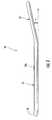
- FIG. 1is a top plan view of the bone fixation device implanted on a radius bone of a patient, according to the present invention.
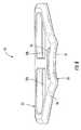
- FIG. 2is a perspective view of the primary bone plate according to the present invention.
- FIG. 3is a side elevational view of the primary bone plate of FIG. 2 .
- FIG. 4is a top plan view of the primary bone plate of FIG. 2 .
- FIG. 5is a bottom plan view of the primary bone plate of FIG. 2 .
- FIG. 6is a front elevational view of the primary bone plate of FIG. 2 .
- FIG. 7is a perspective view of the first secondary bone plate according to the present invention.
- FIG. 8is a bottom plan view of the secondary bone plate of FIG. 7 .
- FIG. 9is a side elevational view of the secondary bone plate of FIG. 7 .
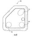
- FIG. 10is a perspective view of another secondary bone plate according to the present invention.
- the bone fixation device 27may be used in bone fixation treatments, i.e. open reduction internal fixation (ORIF).
- the bone fixation device 27may be used to treat a fractured long bone, for example, the illustrated radius bone 21 ( FIG. 1 ), in a patient, more particularly, a distal juxta-articular radius bone fracture.
- the bone fixation device 27may be used on other long bones in the patient, for example, the femur bone, the tibia bone, the fibula bones of the legs, and the humerus bones. Moreover, as also appreciated by those skilled in the art, the bone fixation device 27 may be implanted on either the volar side or the dorsal side of the radius bone 21 .
- the bone fixation device 27illustratively includes a primary bone plate 20 and a plurality of secondary bone plates 30 a - 30 b .
- the primary bone plate 20illustratively includes an elongate member 23 having a plurality of first fastener-receiving passageways 24 a - 24 c therein to receive a plurality of first fasteners 25 a - 25 c to anchor the primary bone plate to the radius bone 21 of a patient. More particularly, the elongate member 23 may be anchored to a diaphysis of the radius bone 21 . As perhaps best seen in FIG. 6 , the elongate member 23 illustratively has an arcuate shape, which may better fit the diaphysis of the radius bone 21 .
- the primary bone plate 20is anatomically contoured to match the surface of the radius bone 21 .
- the elongate member 23can be completely planar or flat.
- the elongate member 23illustratively defines a longitudinal axis 39 ( FIG. 4 ).
- the primary bone plate 20illustratively has rounded corner portions 26 , thereby providing greater comfort to the patient after implantation.
- the primary bone plate 20further illustratively includes an enlarged head member 22 extending from the elongate member 23 .
- the angle between the longitudinal axis 39 of the elongate member 23 and the transverse axis of the enlarged head member 22can be variable and be in the range of approximately 45 to 90 degrees.
- the elongate member 23 and the enlarged head member 22are illustratively connected at a canted angle ⁇ of 11 degrees. In other embodiments, the canted angle may be in a range of 5 to 20 degrees.
- the enlarged head member 23illustratively includes a plurality of secondary bone plate-receiving passageways 32 a - 32 b therein.
- the secondary bone plates 30 a - 30 bare illustratively received in respective secondary bone plate-receiving passageways 32 a - 32 b .
- the secondary bone plate-receiving passageways 32 a - 32 billustratively form a pair thereof arranged in side-by-side relation on opposite sides of the longitudinal axis 39 .
- the primary bone plate 20also illustratively includes a pair of passageways 28 a - 28 b . As will be appreciated by those skilled in the art, these passageways 28 a - 28 b may aid in positioning the primary bone plate 20 and the bone fragments during implantation, for example, by inserting Kirschner wire (K-wire) therethrough. Moreover, the primary bone plate 20 also illustratively includes a medial opening 36 . As will be appreciated by those skilled in the art, the medial opening 36 may permit application of bone graft material during implantation to aid in the bone healing process.
- K-wireKirschner wire
- each secondary bone plate 30 a - 30 billustratively includes a plurality of second fastener-receiving passageways 35 a - 35 c , 33 a - 33 c therein to receive a plurality of second fasteners 31 a - 31 f to anchor the secondary bone plates to fractured distal portions of the radius bone 21 of the patient. More particularly, the secondary bone plates 30 a - 30 b fix together the fractured epiphysis of the radius bone 21 .
- the first 25 a - 25 c and second fasteners 31 a - 31 fmay comprise the illustrated surgical screws or pegs, for example.
- the bottom sides 35 of the secondary bone plates 30 a - 30 bare flanged.
- the secondary bone plate-receiving passageways 32 a - 32 bprovide a rim or ledge of sorts for the secondary bone plates 30 a - 30 b .
- each secondary bone plates 30 a - 30 bcan be received by both secondary bone plate-receiving passageways 32 a - 32 b , thereby providing flexibility during implantation. Since each secondary bone plate 30 a - 30 b has a different arrangement of the second fastener-receiving passageways 35 a - 35 c , 33 a - 33 c , the secondary bone plates may be oriented to best fit the fracture of the radius bone 21 .
- the secondary bone plates 30 a - 30 bmay include tabs extending from the sides thereof. The tabs may cooperate with corresponding openings in the secondary bone plate-receiving passageways 32 a - 32 b for aiding in holding the secondary bone plates to the primary bone plate 20 during implantation but before insertion of the second fasteners 31 a - 31 f.
- the secondary bone plates 30 a - 30 b and the respective secondary bone plate-receiving passageways 32 a - 32 billustratively have a generally rectangular shape with a corner portion cut therefrom, but can alternatively be contoured in several ways to still permit the orientation of the secondary bone plates 30 a - 30 b and its passageways (second fastener-receiving passageways 35 a - 35 c , 33 a - 33 c ) for fasteners to optimize fracture fragment stabilization. Nonetheless, in other embodiments, not shown, the shape may alternatively be generally rectangular or trapezoidal, for example.
- the bone fixation device 27may include more than two secondary bone plates, for example, symmetrically oriented, or only one rotatable secondary bone plate, i.e. the single secondary bone plate may be oriented in a plurality of positions.
- the secondary bone plates 30 a - 30 bmay have flanged bottom and top sides, thereby permitting the secondary bone plate to be flipped to inverse orientation of the second fastener-receiving passageways 35 a - 35 c , 33 a - 33 c.
- two 33 c , 35 c of the second fastener-receiving passageways 35 a - 35 c , 33 a - 33 care illustratively angled from normal to the secondary bone plate 30 a - 30 b , i.e. hooded openings.
- the angle ⁇ ( FIG. 9 ) of canting for the second fastener-receiving passageways 33 c , 35 cis illustratively 37 degrees.
- the angle ⁇can be created by either elevating the “hood” that is designed to receive the secondary fastener or recessing the passageway to create a similar angle of passage for the second fasteners 31 a - 31 f into the fracture fragment.
- the angled second fastener-receiving passageways 33 c , 35 cmay more readily fix together fragmented portions of the distal radius bone 21 .
- the secondary bone plates 30 a - 30 bmay comprise no angled second fastener-receiving passageways or more than the illustrated two ( FIG. 1 ), i.e.
- the second fastener-receiving passageways 35 a - 35 c , 33 a - 33 cmay be recessed (excavated) and optionally angled, and combined with planar and/or hooded embodiments.
- the recessed second fastener-receiving passagewaysmay reduce attrition of soft tissue over the implanted bone fixation device 27 .
- the bone fixation device 27may be used in cost sensitive applications, i.e. ambulatory surgery centers (ASC), for example, since the facility may stock fewer parts because the surgeon would have the flexibility and capability to build “custom” devices that adapt to a variety of patient anatomies and fracture patterns.
- ASCambulatory surgery centers
- the medical facilitymay stock fewer primary 20 and secondary bone plates 30 a - 30 b . More so, each secondary bone plate 30 a - 30 b illustratively has a different pattern of the second fastener-receiving passageways 35 a - 35 c , 33 a - 33 c therein.
- the bone fixation device 27may be customized to the particular fracture of the radius bone 21 without having to stock of large inventory of differing bone plates. This strategy may optimize patient care while demonstrating a fiscal sensitivity.
- the first fastener-receiving passageways 24 a - 24 c and the second fastener-receiving passageways 35 a - 35 c , 33 a - 33 care illustratively countersunk.
- thisprovides that the head portions of the first 25 a - 25 c and second fasteners 31 a - 31 f do not extend beyond a surface of the elongate member 20 and the secondary bone plates 30 a - 30 b , respectively.
- first fastener-receiving passageways 24 a - 24 c and the second fastener-receiving passageways 35 a - 35 c , 33 a - 33 cmay have threaded surfaces for engaging the threaded surfaces of the respective fasteners considered “locking screws” 25 a - 25 c , 31 a - 31 f , thereby providing a more rigid and durable bone fixation.
- elongated passagewayssuch as the illustrated first fastener-receiving passageway 24 b , may or may not have threaded surfaces.
- this bone fixation device 27may be used in conjunction with supplemental bone fixation devices, for example, as disclosed in U.S. patent application Ser. No. 12/114,619 to Graham et al., also assigned to the present application's assignee.
- the methodmay comprise providing a primary bone plate 22 , as described above in detail.
- the methodmay also include selecting at least one secondary bone plate 30 a - 30 b , as described above in detail.
- the methodmay include using first fasteners 25 a - 25 c to anchor the primary bone plate 22 to the radius bone 21 of the patient, and using second fasteners 31 a - 31 f to anchor the secondary bone plate 20 to the fractured distal portions of the radius bone of the patient.
- the first fasteners 25 a - 25 cmay be implanted before the second fasteners 31 a - 31 f or vice versa.
Landscapes
- Health & Medical Sciences (AREA)
- Orthopedic Medicine & Surgery (AREA)
- Surgery (AREA)
- Life Sciences & Earth Sciences (AREA)
- Heart & Thoracic Surgery (AREA)
- Nuclear Medicine, Radiotherapy & Molecular Imaging (AREA)
- Engineering & Computer Science (AREA)
- Biomedical Technology (AREA)
- Neurology (AREA)
- Medical Informatics (AREA)
- Molecular Biology (AREA)
- Animal Behavior & Ethology (AREA)
- General Health & Medical Sciences (AREA)
- Public Health (AREA)
- Veterinary Medicine (AREA)
- Surgical Instruments (AREA)
- Prostheses (AREA)
Abstract
Description
Claims (22)
Priority Applications (1)
| Application Number | Priority Date | Filing Date | Title |
|---|---|---|---|
| US12/203,221US8231625B2 (en) | 2008-09-03 | 2008-09-03 | Modular bone fixation device for treatment of fractures and related methods |
Applications Claiming Priority (1)
| Application Number | Priority Date | Filing Date | Title |
|---|---|---|---|
| US12/203,221US8231625B2 (en) | 2008-09-03 | 2008-09-03 | Modular bone fixation device for treatment of fractures and related methods |
Publications (2)
| Publication Number | Publication Date |
|---|---|
| US20100057132A1 US20100057132A1 (en) | 2010-03-04 |
| US8231625B2true US8231625B2 (en) | 2012-07-31 |
Family
ID=41726505
Family Applications (1)
| Application Number | Title | Priority Date | Filing Date |
|---|---|---|---|
| US12/203,221Active2031-06-01US8231625B2 (en) | 2008-09-03 | 2008-09-03 | Modular bone fixation device for treatment of fractures and related methods |
Country Status (1)
| Country | Link |
|---|---|
| US (1) | US8231625B2 (en) |
Cited By (12)
| Publication number | Priority date | Publication date | Assignee | Title |
|---|---|---|---|---|
| US20110276097A1 (en)* | 2010-05-07 | 2011-11-10 | Osteomed L.P. | System for Treating Bone Fractures |
| US20120209334A1 (en)* | 2011-02-15 | 2012-08-16 | Orthohelix Surgical Designs, Inc. | Orthopedic compression plate |
| US8518042B2 (en)* | 2010-10-19 | 2013-08-27 | Biomet Manufacturing, Llc | Orthopedic plate assembly for a distal radius having re-contouring features and method for using same |
| US20130238032A1 (en)* | 2012-03-06 | 2013-09-12 | Stryker Trauma Sa | Bone plate and aiming block |
| US8858644B2 (en) | 2009-01-08 | 2014-10-14 | Memometal Technologies | Orthopaedic implant for arthroplasty of the fingers |
| US9408647B2 (en) | 2014-02-27 | 2016-08-09 | Biomedical Enterprises, Inc. | Method and apparatus for use of a compressing plate |
| US9572607B2 (en) | 2009-07-09 | 2017-02-21 | Orthohelix Surgical Designs, Inc. | Osteotomy plate, plate driver and method for their use |
| US9597192B2 (en) | 2014-06-02 | 2017-03-21 | Stryker European Holdings I, Llc | Metacarpal rod anchor for a trapezometacarpal prosthesis |
| US9883897B2 (en) | 2014-09-25 | 2018-02-06 | Biomedical Enterprises, Inc. | Method and apparatus for a compressing plate |
| US9907588B2 (en) | 2012-09-06 | 2018-03-06 | Orthohelix Surgical Designs, Inc. | Orthopedic dual pocket compression plate and method of surgery |
| US10213236B2 (en) | 2011-12-28 | 2019-02-26 | Orthohelix Surgical Designs, Inc. | Orthopedic compression plate and method of surgery |
| US11020148B2 (en) | 2019-08-07 | 2021-06-01 | Crossroads Extremity Systems, Llc | Bunion correction system and method |
Families Citing this family (8)
| Publication number | Priority date | Publication date | Assignee | Title |
|---|---|---|---|---|
| US20070198016A1 (en)* | 2006-02-21 | 2007-08-23 | Osteomed, L.P. | Compression stabilizing spacers |
| CN104068925B (en) | 2008-03-26 | 2017-07-14 | 斯恩蒂斯有限公司 | For the universal anchor by physical attachment on bone tissue |
| CN102046111A (en) | 2008-06-05 | 2011-05-04 | 斯恩蒂斯有限公司 | Articulating disc implant |
| FR2956972B1 (en) | 2010-03-08 | 2012-12-28 | Memometal Technologies | ARTICULATED OSTEOSYNTHESIS PLATE |
| FR2956971B1 (en) | 2010-03-08 | 2012-03-02 | Memometal Technologies | PLATE OSTEOSYNTHESIS SYSTEM |
| CA2882601C (en)* | 2012-08-22 | 2020-10-27 | Andreas Appenzeller | Anchor-in-anchor system |
| GB2532721B (en)* | 2014-11-21 | 2021-02-10 | Everost Uk Ltd | Bone fixation plate |
| WO2016126996A1 (en)* | 2015-02-06 | 2016-08-11 | In2Bones Usa, Llc | Bone plate with insert(s) for optimally directing fasteners |
Citations (38)
| Publication number | Priority date | Publication date | Assignee | Title |
|---|---|---|---|---|
| US4164793A (en) | 1978-04-26 | 1979-08-21 | Swanson Alfred B | Lunate implant |
| US4198712A (en) | 1978-10-13 | 1980-04-22 | Swanson Alfred B | Scaphoid implant |
| US4936860A (en) | 1988-09-23 | 1990-06-26 | Swanson Alfred B | Metal scaphoid implant |
| US4969908A (en) | 1989-06-02 | 1990-11-13 | Swanson Alfred B | Lunate implant and method of stabilizing same |
| US5314485A (en) | 1991-09-12 | 1994-05-24 | Etablissements Tornier | Total prosthesis of the wrist |
| US5326364A (en) | 1992-12-16 | 1994-07-05 | Wright Medical Technology, Inc. | Trapezial implant |
| US5360431A (en) | 1990-04-26 | 1994-11-01 | Cross Medical Products | Transpedicular screw system and method of use |
| WO1996003084A1 (en) | 1994-07-26 | 1996-02-08 | University Of Akron, The | Device and method for restoration of connective tissue |
| US5645605A (en) | 1995-09-18 | 1997-07-08 | Ascension Orthopedics, Inc. | Implant device to replace the carpometacarpal joint of the human thumb |
| US5827285A (en) | 1996-12-12 | 1998-10-27 | Bramlet; Dale G. | Multipiece interfragmentary fixation assembly |
| US5984926A (en) | 1998-02-24 | 1999-11-16 | Jones; A. Alexander M. | Bone screw shimming and bone graft containment system and method |
| US5984970A (en) | 1996-03-13 | 1999-11-16 | Bramlet; Dale G. | Arthroplasty joint assembly |
| US6221074B1 (en) | 1999-06-10 | 2001-04-24 | Orthodyne, Inc. | Femoral intramedullary rod system |
| US6283969B1 (en) | 2000-03-10 | 2001-09-04 | Wright Medical Technology, Inc. | Bone plating system |
| US6302887B1 (en) | 1998-07-20 | 2001-10-16 | Joseph John Spranza | Hardware for high strength fastening of bone |
| US6440135B2 (en) | 2000-02-01 | 2002-08-27 | Hand Innovations, Inc. | Volar fixation system with articulating stabilization pegs |
| US6565960B2 (en) | 2000-06-01 | 2003-05-20 | Shriners Hospital Of Children | Polymer composite compositions |
| US6699292B2 (en) | 2000-11-28 | 2004-03-02 | Ascension Orthopedics, Inc. | Interphalangeal joint replacement |
| US20040097935A1 (en)* | 2002-03-12 | 2004-05-20 | Marc Richelsoph | Bone plate and screw retaining mechanism |
| US20040138754A1 (en) | 2002-10-07 | 2004-07-15 | Imaging Therapeutics, Inc. | Minimally invasive joint implant with 3-Dimensional geometry matching the articular surfaces |
| US20040158251A1 (en) | 1999-04-16 | 2004-08-12 | Morrison Matthew M. | Multi-axial bone anchor system |
| US20050049710A1 (en) | 2003-08-28 | 2005-03-03 | O'driscoll Shawn W. | Prosthesis for partial replacement of an articulating surface on bone |
| US20050070902A1 (en) | 2003-09-30 | 2005-03-31 | Medoff Robert J. | Intramedullary implant for fracture fixation |
| US20050216090A1 (en) | 2004-03-11 | 2005-09-29 | O'driscoll Shawn W | Systems for bone replacement |
| US20050234458A1 (en) | 2004-04-19 | 2005-10-20 | Huebner Randall J | Expanded stabilization of bones |
| US20050245931A1 (en)* | 2000-02-01 | 2005-11-03 | Orbay Jorge L | Volar fixation system |
| US20060015101A1 (en) | 2004-07-15 | 2006-01-19 | Wright Medical Technology, Inc. | Intramedullary fixation assembly and devices and methods for installing the same |
| US20060089648A1 (en) | 2004-10-27 | 2006-04-27 | Masini Michael A | Versatile bone plate systems particularly suited to minimally invasive surgical procedures |
| US20060155284A1 (en) | 2005-01-07 | 2006-07-13 | Depuy Spine Sarl | Occipital plate and guide systems |
| US20060173458A1 (en) | 2004-10-07 | 2006-08-03 | Micah Forstein | Bone fracture fixation system |
| US7090676B2 (en) | 2002-11-19 | 2006-08-15 | Acumed Llc | Adjustable bone plates |
| US20070014649A1 (en) | 2003-04-23 | 2007-01-18 | James Dugal S S | Fixation device and method of fixation |
| US20070043357A1 (en) | 2005-07-29 | 2007-02-22 | X-Spine Systems, Inc. | Capless multiaxial screw and spinal fixation assembly and method |
| US7189237B2 (en) | 2002-11-19 | 2007-03-13 | Acumed Llc | Deformable bone plates |
| US20070083202A1 (en) | 2005-09-20 | 2007-04-12 | Donald Eli Running | Intramedullary bone plate with sheath |
| US20070173834A1 (en) | 2004-04-12 | 2007-07-26 | Thakkar Navin N | Flexible Nail Assembly For Fractures Of Long Bones |
| US20070173841A1 (en) | 2006-01-18 | 2007-07-26 | Ralph James D | Adjustable bone plate |
| US20070265629A1 (en) | 2006-03-07 | 2007-11-15 | Amanda Martin | Distal radius plate |
- 2008
- 2008-09-03USUS12/203,221patent/US8231625B2/enactiveActive
Patent Citations (43)
| Publication number | Priority date | Publication date | Assignee | Title |
|---|---|---|---|---|
| US4164793A (en) | 1978-04-26 | 1979-08-21 | Swanson Alfred B | Lunate implant |
| US4198712A (en) | 1978-10-13 | 1980-04-22 | Swanson Alfred B | Scaphoid implant |
| US4936860A (en) | 1988-09-23 | 1990-06-26 | Swanson Alfred B | Metal scaphoid implant |
| US4969908A (en) | 1989-06-02 | 1990-11-13 | Swanson Alfred B | Lunate implant and method of stabilizing same |
| US5360431A (en) | 1990-04-26 | 1994-11-01 | Cross Medical Products | Transpedicular screw system and method of use |
| US5314485A (en) | 1991-09-12 | 1994-05-24 | Etablissements Tornier | Total prosthesis of the wrist |
| US5326364A (en) | 1992-12-16 | 1994-07-05 | Wright Medical Technology, Inc. | Trapezial implant |
| WO1996003084A1 (en) | 1994-07-26 | 1996-02-08 | University Of Akron, The | Device and method for restoration of connective tissue |
| US5645605A (en) | 1995-09-18 | 1997-07-08 | Ascension Orthopedics, Inc. | Implant device to replace the carpometacarpal joint of the human thumb |
| US6475242B1 (en) | 1996-03-13 | 2002-11-05 | Dale G. Bramlet | Arthroplasty joint assembly |
| US5984970A (en) | 1996-03-13 | 1999-11-16 | Bramlet; Dale G. | Arthroplasty joint assembly |
| US5827285A (en) | 1996-12-12 | 1998-10-27 | Bramlet; Dale G. | Multipiece interfragmentary fixation assembly |
| US5984926A (en) | 1998-02-24 | 1999-11-16 | Jones; A. Alexander M. | Bone screw shimming and bone graft containment system and method |
| WO2001024717A1 (en) | 1998-02-24 | 2001-04-12 | Jones A Alexander M | Bone screw shimming and bone graft containment system and method |
| US6302887B1 (en) | 1998-07-20 | 2001-10-16 | Joseph John Spranza | Hardware for high strength fastening of bone |
| US20040158251A1 (en) | 1999-04-16 | 2004-08-12 | Morrison Matthew M. | Multi-axial bone anchor system |
| US6221074B1 (en) | 1999-06-10 | 2001-04-24 | Orthodyne, Inc. | Femoral intramedullary rod system |
| US6440135B2 (en) | 2000-02-01 | 2002-08-27 | Hand Innovations, Inc. | Volar fixation system with articulating stabilization pegs |
| US20050245931A1 (en)* | 2000-02-01 | 2005-11-03 | Orbay Jorge L | Volar fixation system |
| US6283969B1 (en) | 2000-03-10 | 2001-09-04 | Wright Medical Technology, Inc. | Bone plating system |
| US6565960B2 (en) | 2000-06-01 | 2003-05-20 | Shriners Hospital Of Children | Polymer composite compositions |
| US6821530B2 (en) | 2000-06-01 | 2004-11-23 | Shriners Hospitals For Children | Polymer composite compositions |
| US6699292B2 (en) | 2000-11-28 | 2004-03-02 | Ascension Orthopedics, Inc. | Interphalangeal joint replacement |
| US20040097935A1 (en)* | 2002-03-12 | 2004-05-20 | Marc Richelsoph | Bone plate and screw retaining mechanism |
| US20040138754A1 (en) | 2002-10-07 | 2004-07-15 | Imaging Therapeutics, Inc. | Minimally invasive joint implant with 3-Dimensional geometry matching the articular surfaces |
| US7189237B2 (en) | 2002-11-19 | 2007-03-13 | Acumed Llc | Deformable bone plates |
| US7090676B2 (en) | 2002-11-19 | 2006-08-15 | Acumed Llc | Adjustable bone plates |
| US7326212B2 (en) | 2002-11-19 | 2008-02-05 | Acumed Llc | Bone plates with reference marks |
| US20070014649A1 (en) | 2003-04-23 | 2007-01-18 | James Dugal S S | Fixation device and method of fixation |
| US20050049710A1 (en) | 2003-08-28 | 2005-03-03 | O'driscoll Shawn W. | Prosthesis for partial replacement of an articulating surface on bone |
| US20050070902A1 (en) | 2003-09-30 | 2005-03-31 | Medoff Robert J. | Intramedullary implant for fracture fixation |
| US20050216090A1 (en) | 2004-03-11 | 2005-09-29 | O'driscoll Shawn W | Systems for bone replacement |
| US20070173834A1 (en) | 2004-04-12 | 2007-07-26 | Thakkar Navin N | Flexible Nail Assembly For Fractures Of Long Bones |
| US20050234458A1 (en) | 2004-04-19 | 2005-10-20 | Huebner Randall J | Expanded stabilization of bones |
| US20060015101A1 (en) | 2004-07-15 | 2006-01-19 | Wright Medical Technology, Inc. | Intramedullary fixation assembly and devices and methods for installing the same |
| US20060173458A1 (en) | 2004-10-07 | 2006-08-03 | Micah Forstein | Bone fracture fixation system |
| US20060089648A1 (en) | 2004-10-27 | 2006-04-27 | Masini Michael A | Versatile bone plate systems particularly suited to minimally invasive surgical procedures |
| US20060155284A1 (en) | 2005-01-07 | 2006-07-13 | Depuy Spine Sarl | Occipital plate and guide systems |
| US20070043357A1 (en) | 2005-07-29 | 2007-02-22 | X-Spine Systems, Inc. | Capless multiaxial screw and spinal fixation assembly and method |
| US20070123867A1 (en) | 2005-07-29 | 2007-05-31 | X-Spine Systems, Inc. | Capless multiaxial screw and spinal fixation assembly and method |
| US20070083202A1 (en) | 2005-09-20 | 2007-04-12 | Donald Eli Running | Intramedullary bone plate with sheath |
| US20070173841A1 (en) | 2006-01-18 | 2007-07-26 | Ralph James D | Adjustable bone plate |
| US20070265629A1 (en) | 2006-03-07 | 2007-11-15 | Amanda Martin | Distal radius plate |
Non-Patent Citations (6)
| Title |
|---|
| Anatomidesign, Ascension® PIP PyroCarbon Total Joint. |
| SBI Small Bone Innovations, SCS(TM) Volar Distal Radius Plate Sytem, Surgical Technique, 2006, pp. 1-9. |
| SBI Small Bone Innovations, SCS(TM)Volar Distal Radius Plate, 2008. |
| SBI Small Bone Innovations, SCS™ Volar Distal Radius Plate Sytem, Surgical Technique, 2006, pp. 1-9. |
| SBI Small Bone Innovations, SCS™Volar Distal Radius Plate, 2008. |
| TONIER US, Medical Professionals, Wrist Products, CoverLoc Volar Plate, 2008. |
Cited By (27)
| Publication number | Priority date | Publication date | Assignee | Title |
|---|---|---|---|---|
| US8858644B2 (en) | 2009-01-08 | 2014-10-14 | Memometal Technologies | Orthopaedic implant for arthroplasty of the fingers |
| US11864803B2 (en) | 2009-07-09 | 2024-01-09 | Orthohelix Surgical Designs, Inc. | Osteotomy plate, plate driver and method for their use |
| US10368926B2 (en)* | 2009-07-09 | 2019-08-06 | Orthohelix Surgical Designs, Inc. | Osteotomy plate, plate driver and method for their use |
| US12268424B2 (en) | 2009-07-09 | 2025-04-08 | Stryker Corporation | Osteotomy plate, plate driver and method for their use |
| US9888949B2 (en)* | 2009-07-09 | 2018-02-13 | Orthohelix Surgical Designs, Inc. | Osteotomy plate, plate driver and method for their use |
| US11337737B2 (en) | 2009-07-09 | 2022-05-24 | Orthohelix Surgical Designs, Inc. | Osteotomy plate, plate driver and method for their use |
| US9572607B2 (en) | 2009-07-09 | 2017-02-21 | Orthohelix Surgical Designs, Inc. | Osteotomy plate, plate driver and method for their use |
| US20170128111A1 (en)* | 2009-07-09 | 2017-05-11 | Orthohelix Surgical Designs, Inc. | Osteotomy plate, plate driver and method for their use |
| US20110276097A1 (en)* | 2010-05-07 | 2011-11-10 | Osteomed L.P. | System for Treating Bone Fractures |
| US9295506B2 (en) | 2010-05-07 | 2016-03-29 | Osteomed Llc | System for treating bone fractures |
| US9066766B2 (en)* | 2010-05-07 | 2015-06-30 | Osteomed Llc | System for treating bone fractures |
| US8518042B2 (en)* | 2010-10-19 | 2013-08-27 | Biomet Manufacturing, Llc | Orthopedic plate assembly for a distal radius having re-contouring features and method for using same |
| US9173690B2 (en) | 2010-10-19 | 2015-11-03 | Biomet Manufacturing, Llc | Orthopedic plate assembly for a distal radius having re-contouring features and method for using same |
| US9005255B2 (en)* | 2011-02-15 | 2015-04-14 | Orthohelix Surgical Designs, Inc. | Orthopedic compression plate |
| US20120209334A1 (en)* | 2011-02-15 | 2012-08-16 | Orthohelix Surgical Designs, Inc. | Orthopedic compression plate |
| US12016600B2 (en) | 2011-12-28 | 2024-06-25 | Orthohelix Surgical Designs, Inc. | Orthopedic compression plate and method of surgery |
| US11317952B2 (en)* | 2011-12-28 | 2022-05-03 | Orthohelix Surgical Designs, Inc. | Orthopedic compression plate and method of surgery |
| US10213236B2 (en) | 2011-12-28 | 2019-02-26 | Orthohelix Surgical Designs, Inc. | Orthopedic compression plate and method of surgery |
| US9050151B2 (en)* | 2012-03-06 | 2015-06-09 | Stryker Trauma Sa | Bone plate and aiming block |
| US20130238032A1 (en)* | 2012-03-06 | 2013-09-12 | Stryker Trauma Sa | Bone plate and aiming block |
| US10736677B2 (en) | 2012-09-06 | 2020-08-11 | Orthohelix Surgical Designs, Inc. | Orthopedic dual pocket compression plate and method of surgery |
| US9907588B2 (en) | 2012-09-06 | 2018-03-06 | Orthohelix Surgical Designs, Inc. | Orthopedic dual pocket compression plate and method of surgery |
| US9408647B2 (en) | 2014-02-27 | 2016-08-09 | Biomedical Enterprises, Inc. | Method and apparatus for use of a compressing plate |
| US9597192B2 (en) | 2014-06-02 | 2017-03-21 | Stryker European Holdings I, Llc | Metacarpal rod anchor for a trapezometacarpal prosthesis |
| US9883897B2 (en) | 2014-09-25 | 2018-02-06 | Biomedical Enterprises, Inc. | Method and apparatus for a compressing plate |
| US11020148B2 (en) | 2019-08-07 | 2021-06-01 | Crossroads Extremity Systems, Llc | Bunion correction system and method |
| US12402915B2 (en) | 2019-08-07 | 2025-09-02 | Crossroads Extremity Systems, Llc | Bunion correction system and method |
Also Published As
| Publication number | Publication date |
|---|---|
| US20100057132A1 (en) | 2010-03-04 |
Similar Documents
| Publication | Publication Date | Title |
|---|---|---|
| US8231625B2 (en) | Modular bone fixation device for treatment of fractures and related methods | |
| JP4421474B2 (en) | Intramedullary fixation device for long bone metaphyseal fractures | |
| AU2009293201B2 (en) | Intramedullary arthrodesis nail and method of use | |
| EP1429674B1 (en) | Fixation device | |
| US6730090B2 (en) | Fixation device for metaphyseal long bone fractures | |
| US5006120A (en) | Distal radial fracture set and method for repairing distal radial fractures | |
| EP2482739B1 (en) | Surgical implant | |
| US20120010667A1 (en) | Fracture-specific distal radius plates | |
| US20070191855A1 (en) | Fracture fixation device and implantation jig therefor | |
| US20060149257A1 (en) | Fracture fixation device | |
| US9968389B2 (en) | Fracture plating | |
| Jung et al. | Biologic fixation through bridge plating for comminuted shaft fracture of the clavicle: technical aspects and prospective clinical experience with a minimum of 12-month follow-up | |
| JP2019166319A (en) | Bone stabilization systems | |
| US20190216611A1 (en) | Grooved slot allowing adjustment of the position of a bone fixation device for osteosynthesis | |
| WO2005048888A1 (en) | A surgical procedure | |
| US20120016366A1 (en) | Proximal Radius Locking Plate | |
| US10194961B2 (en) | Prosthesis | |
| WO2007086854A1 (en) | A fracture fixation device and implantation jig therefor | |
| Park et al. | PHILOS plate osteosynthesis in metaphyseal fractures of the distal humerus through an anterolateral approach | |
| US20130325122A1 (en) | Low contact femoral and tibial bases | |
| Suresh | Functional outcome of middle third humeral shaft fractures treated with anteromedial plate osteosynthesis through an anterolateral approach | |
| TWM537878U (en) | A securing device for a proximal radius | |
| WO2024238198A1 (en) | Orthopedic intramedullary nail system for greater trochanter fixation | |
| WO2021137824A1 (en) | Cable-supported cannulated screw | |
| Huebner et al. | Clinical Applications of the F3® Fragment Plating System in the Upper Extremity: A Series of Case Examples |
Legal Events
| Date | Code | Title | Description |
|---|---|---|---|
| AS | Assignment | Owner name:MIMEDX, INC.,FLORIDA Free format text:ASSIGNMENT OF ASSIGNORS INTEREST;ASSIGNORS:GRAHAM, THOMAS JAMES, M.D.;FOCHT, LOUISE M.;SIGNING DATES FROM 20080909 TO 20081105;REEL/FRAME:021815/0926 Owner name:MIMEDX, INC., FLORIDA Free format text:ASSIGNMENT OF ASSIGNORS INTEREST;ASSIGNORS:GRAHAM, THOMAS JAMES, M.D.;FOCHT, LOUISE M.;SIGNING DATES FROM 20080909 TO 20081105;REEL/FRAME:021815/0926 | |
| AS | Assignment | Owner name:UPEX HOLDINGS, LLC,WEST VIRGINIA Free format text:ASSIGNMENT OF ASSIGNORS INTEREST;ASSIGNOR:MIMEDX, INC.;REEL/FRAME:023411/0255 Effective date:20091016 Owner name:UPEX HOLDINGS, LLC, WEST VIRGINIA Free format text:ASSIGNMENT OF ASSIGNORS INTEREST;ASSIGNOR:MIMEDX, INC.;REEL/FRAME:023411/0255 Effective date:20091016 | |
| STCF | Information on status: patent grant | Free format text:PATENTED CASE | |
| FPAY | Fee payment | Year of fee payment:4 | |
| MAFP | Maintenance fee payment | Free format text:PAYMENT OF MAINTENANCE FEE, 8TH YR, SMALL ENTITY (ORIGINAL EVENT CODE: M2552); ENTITY STATUS OF PATENT OWNER: SMALL ENTITY Year of fee payment:8 | |
| MAFP | Maintenance fee payment | Free format text:PAYMENT OF MAINTENANCE FEE, 12TH YR, SMALL ENTITY (ORIGINAL EVENT CODE: M2553); ENTITY STATUS OF PATENT OWNER: SMALL ENTITY Year of fee payment:12 |