US8231545B2 - Rotational core biopsy device with liquid cryogen adhesion probe - Google Patents
Rotational core biopsy device with liquid cryogen adhesion probeDownload PDFInfo
- Publication number
- US8231545B2 US8231545B2US12/611,085US61108509AUS8231545B2US 8231545 B2US8231545 B2US 8231545B2US 61108509 AUS61108509 AUS 61108509AUS 8231545 B2US8231545 B2US 8231545B2
- Authority
- US
- United States
- Prior art keywords
- canister
- adhesion probe
- valve
- cannula
- probe
- Prior art date
- Legal status (The legal status is an assumption and is not a legal conclusion. Google has not performed a legal analysis and makes no representation as to the accuracy of the status listed.)
- Expired - Fee Related, expires
Links
- 239000000523sampleSubstances0.000titleclaimsdescription83
- 238000001574biopsyMethods0.000titleabstractdescription46
- 239000007788liquidSubstances0.000titleabstractdescription19
- 230000007246mechanismEffects0.000claimsdescription14
- 239000012530fluidSubstances0.000claimsdescription10
- 210000000481breastAnatomy0.000claimsdescription8
- 238000005070samplingMethods0.000claimsdescription8
- 230000000994depressogenic effectEffects0.000claimsdescription4
- 206010028980NeoplasmDiseases0.000description31
- CURLTUGMZLYLDI-UHFFFAOYSA-NCarbon dioxideChemical compoundO=C=OCURLTUGMZLYLDI-UHFFFAOYSA-N0.000description21
- 229910002092carbon dioxideInorganic materials0.000description21
- 238000000034methodMethods0.000description12
- 230000003902lesionEffects0.000description10
- GQPLMRYTRLFLPF-UHFFFAOYSA-NNitrous OxideChemical compound[O-][N+]#NGQPLMRYTRLFLPF-UHFFFAOYSA-N0.000description9
- 201000011510cancerDiseases0.000description9
- 210000004027cellAnatomy0.000description9
- 239000002826coolantSubstances0.000description9
- 230000000149penetrating effectEffects0.000description9
- 238000001816coolingMethods0.000description8
- 239000007789gasSubstances0.000description6
- 238000013519translationMethods0.000description6
- 238000003745diagnosisMethods0.000description5
- 208000026310Breast neoplasmDiseases0.000description4
- 239000001272nitrous oxideSubstances0.000description4
- 238000002271resectionMethods0.000description4
- 238000007710freezingMethods0.000description3
- 230000008014freezingEffects0.000description3
- 230000000977initiatory effectEffects0.000description3
- 230000037361pathwayEffects0.000description3
- 210000004881tumor cellAnatomy0.000description3
- XKRFYHLGVUSROY-UHFFFAOYSA-NArgonChemical compound[Ar]XKRFYHLGVUSROY-UHFFFAOYSA-N0.000description2
- ATUOYWHBWRKTHZ-UHFFFAOYSA-NPropaneChemical compoundCCCATUOYWHBWRKTHZ-UHFFFAOYSA-N0.000description2
- 238000010276constructionMethods0.000description2
- 238000010586diagramMethods0.000description2
- 239000006185dispersionSubstances0.000description2
- VNWKTOKETHGBQD-UHFFFAOYSA-NmethaneChemical compoundCVNWKTOKETHGBQD-UHFFFAOYSA-N0.000description2
- 230000004044responseEffects0.000description2
- TXEYQDLBPFQVAA-UHFFFAOYSA-NtetrafluoromethaneChemical compoundFC(F)(F)FTXEYQDLBPFQVAA-UHFFFAOYSA-N0.000description2
- 238000012285ultrasound imagingMethods0.000description2
- 206010006187Breast cancerDiseases0.000description1
- OTMSDBZUPAUEDD-UHFFFAOYSA-NEthaneChemical compoundCCOTMSDBZUPAUEDD-UHFFFAOYSA-N0.000description1
- 208000006994Precancerous ConditionsDiseases0.000description1
- 206010044334TranceDiseases0.000description1
- 229910052786argonInorganic materials0.000description1
- 230000000712assemblyEffects0.000description1
- 238000000429assemblyMethods0.000description1
- 230000008901benefitEffects0.000description1
- 210000001124body fluidAnatomy0.000description1
- 239000010839body fluidSubstances0.000description1
- 239000001569carbon dioxideSubstances0.000description1
- 238000004891communicationMethods0.000description1
- 238000012790confirmationMethods0.000description1
- 230000009133cooperative interactionEffects0.000description1
- 238000005138cryopreservationMethods0.000description1
- 230000006378damageEffects0.000description1
- 208000037765diseases and disordersDiseases0.000description1
- 238000007387excisional biopsyMethods0.000description1
- 238000007667floatingMethods0.000description1
- 239000012634fragmentSubstances0.000description1
- 238000010438heat treatmentMethods0.000description1
- 230000002962histologic effectEffects0.000description1
- 238000003384imaging methodMethods0.000description1
- 238000007386incisional biopsyMethods0.000description1
- 238000003780insertionMethods0.000description1
- 230000037431insertionEffects0.000description1
- 238000012977invasive surgical procedureMethods0.000description1
- 238000003754machiningMethods0.000description1
- 238000009607mammographyMethods0.000description1
- 239000012528membraneSubstances0.000description1
- 238000010899nucleationMethods0.000description1
- 238000012354overpressurizationMethods0.000description1
- 238000002559palpationMethods0.000description1
- 239000012188paraffin waxSubstances0.000description1
- 238000012545processingMethods0.000description1
- 239000001294propaneSubstances0.000description1
- 238000010008shearingMethods0.000description1
- 239000007787solidSubstances0.000description1
- 230000007704transitionEffects0.000description1
- 230000000007visual effectEffects0.000description1
- XLYOFNOQVPJJNP-UHFFFAOYSA-NwaterSubstancesOXLYOFNOQVPJJNP-UHFFFAOYSA-N0.000description1
Images


Classifications
- A—HUMAN NECESSITIES
- A61—MEDICAL OR VETERINARY SCIENCE; HYGIENE
- A61B—DIAGNOSIS; SURGERY; IDENTIFICATION
- A61B10/00—Instruments for taking body samples for diagnostic purposes; Other methods or instruments for diagnosis, e.g. for vaccination diagnosis, sex determination or ovulation-period determination; Throat striking implements
- A61B10/02—Instruments for taking cell samples or for biopsy
- A61B10/0233—Pointed or sharp biopsy instruments
- A61B10/0266—Pointed or sharp biopsy instruments means for severing sample
- A—HUMAN NECESSITIES
- A61—MEDICAL OR VETERINARY SCIENCE; HYGIENE
- A61B—DIAGNOSIS; SURGERY; IDENTIFICATION
- A61B18/00—Surgical instruments, devices or methods for transferring non-mechanical forms of energy to or from the body
- A61B18/02—Surgical instruments, devices or methods for transferring non-mechanical forms of energy to or from the body by cooling, e.g. cryogenic techniques
- A61B18/0218—Surgical instruments, devices or methods for transferring non-mechanical forms of energy to or from the body by cooling, e.g. cryogenic techniques with open-end cryogenic probe, e.g. for spraying fluid directly on tissue or via a tissue-contacting porous tip
- A—HUMAN NECESSITIES
- A61—MEDICAL OR VETERINARY SCIENCE; HYGIENE
- A61B—DIAGNOSIS; SURGERY; IDENTIFICATION
- A61B17/00—Surgical instruments, devices or methods
- A61B2017/00017—Electrical control of surgical instruments
- A61B2017/00199—Electrical control of surgical instruments with a console, e.g. a control panel with a display
- A—HUMAN NECESSITIES
- A61—MEDICAL OR VETERINARY SCIENCE; HYGIENE
- A61B—DIAGNOSIS; SURGERY; IDENTIFICATION
- A61B17/00—Surgical instruments, devices or methods
- A61B2017/00535—Surgical instruments, devices or methods pneumatically or hydraulically operated
- A61B2017/00539—Surgical instruments, devices or methods pneumatically or hydraulically operated hydraulically
Definitions
- the devices and methods described belowrelate to the diagnosis and treatment of breast lesions, and more generally, to the diagnosis and treatment of tumors and lesions throughout the body.
- Biopsyis an important procedure used for the diagnosis of patients with cancerous tumors, pre-malignant conditions, and other diseases and disorders.
- a biopsyis performed. The biopsy will help determine whether the cells are cancerous, the type of cancer, and what treatment should be used to treat the cancer.
- Biopsymay be done by an open or percutaneous technique. Open biopsy, which is an invasive surgical procedure using a scalpel and involving direct vision of the target area, removes the entire mass (excisional biopsy) or a part of the mass (incisional biopsy).
- Percutaneous biopsyis usually done with a needle-like instrument through a relatively small incision, blindly or with the aid of an imaging device, and may be either a fine needle aspiration (FNA) or a core biopsy.
- FNA biopsyindividual cells or clusters of cells are obtained for cytologic examination and may be prepared such as in a Papanicolaou smear.
- core biopsyas the term suggests, a core or fragment of tissue is obtained for histologic examination which may be done via a frozen section or paraffin section.
- One important area where biopsies are performedis the diagnosis of breast tumors.
- the biopsy technique for breast tumorsinvolves placing a biopsy device multiple times into the breast and taking several samples of tissue from a mass or tumor which is suspected of being cancerous. Several samples are required to be sure that some tissue from the suspect mass has been captured, and enough tissue has been sampled to ensure that, if disperse cancer cells exist in the suspect mass some of those cancer cells will be captured in the samples. Each time the device is placed the physician must locate and direct the device with ultrasound imaging into the correct position near the suspect mass. Some breast tumors and lesions are very well defined, hard spherical masses which grow within the soft, compliant breast tissue. It is difficult to force a needle into these lesions because they are resistant to puncture and fairly mobile. Forcing the biopsy needle into the lesion is like trying to spear an apple floating in water.
- Vacuum assisted biopsy systemproposed by Biopsys involves sucking a breast lesion into a cannula and shearing off the captured edge of the lesion to obtain a biopsy sample.
- the deviceuses a vacuum to collect tissue into the side of an open tubular device, and then uses a rotating corer to cut the tissue collected.
- the rotating coreris slidable within the tubular section and can be pulled back to remove the tissue collected in the rotating corer.
- An additional stylet inside the rotating corercan be used to push the tissue out of the corer.
- the devicecan be rotated on its axis to remove a sample, 360 degrees around the central placement of the device.
- physicianssample six to eight cores.
- One advantage of this deviceis that the physician does not have to remove the device for additional biopsy samples.
- Tumorsmay be too tough to yield to the suction and deform as necessary to enter the side opening of the cannula. Doctors also currently use the device to take a circular sequence of cores by rotating the device about its long axis or by sideways movement of the suction head to take a line of cores.
- the tumorAfter biopsy and analysis, the tumor must be treated with a separate device, as Biopsys teaches that their coring device should not be used for resection. Indeed, the device is not designed to perform resection with assurance that complete resection of a suspect mass has been accomplished. Mechanical cutting and disruption of the tissue structure and cancer cell dispersion (that is, tearing of the tissue around the cancer and movement of the cancer cells amongst normal tissue) will result in unintentional delivery of cancer cells into healthy tissue adjacent the lesion.
- the device described belowprovides for diagnosis of tumors within the breast.
- the deviceincludes an adhesion probe with structures that permit the surgeon to secure a suspect mass or tumor within the breast during the biopsy procedure.
- the probeis provided with a rigid tube and a sharp distal tip. To secure the tumor to the probe, the surgeon pierces the tumor with the distal rod. Tubing extending within the rigid tube directs coolant to the distal tip to cool the tip, the tumor then adhering to the cooled probe.
- the devicealso includes a coring apparatus with structures that permit the surgeon to core a sample of the tumor during the biopsy procedure.
- the coring apparatusis provided with an outer cutting cannula that advances through a tumor to core a sample of the tumor.
- the coring apparatusis adapted for use with the probe.
- the adhesion probeis disposed within the cannula with the distal tip of the probe extending beyond the distal tip of the cannula.
- the deviceis inserted into the body until the adhesion probe pierces the tumor. Coolant is directed to the distal tip of the probe to lightly cool the distal tip and the tumor. The lightly cooled distal tip adheres to the tumor cells immediately proximate the distal tip.
- the coring apparatusis actuated to excise tumor tissue surrounding the distal tip.
- the coring apparatuscomprises a cutting cannula and means for rotating and translating the cutting cannula. After coring is complete, the device is removed from the body and the cutting cannula is retracted to release the excised tissue. This method of biopsy prevents destruction of the tumor cells and reduces seeding (the dispersion of tumor cells to healthy cell areas).
- Small canisters of CO 2 , (carbon dioxide) or N 2 O (nitrous oxide), sometimes referred to as whippets,provide the coolant to the device. These small canisters eliminate the need for hoses remotely connected to large coolant canisters and allow the surgeon to freely operate during a procedure without the possibility of severing or tangling coolant supply tubes.
- the use of liquid CO 2facilitates rapid yet moderate freezing of the target tissue lesion proximate the adhesion probe.
- the larger heat capacity of the liquid cryogen, vis-à-vis gaseous cryogen such as Argon gasallows for further miniaturization of the reservoir and cooling probe components, with an overall gain of cooling efficiency and faster cooling operation.
- the liquid CO 2is also used to drive the rotation and longitudinal translation of the biopsy coring apparatus.
- the systemis controlled with various electromechanical interlocks and a microchip programmed to operate the system in response to operator input and various predetermined parameters.
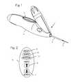
- FIG. 1is an isometric view of the biopsy instrument.
- FIG. 2illustrates the user interface of biopsy instrument illustrated in FIG. 1 .
- FIG. 3is an isometric view of internal components of the biopsy instrument illustrated in FIG. 1 .
- FIG. 4shows a cross-sectional view of the biopsy instrument with the cutting cannula in the retracted position.
- FIG. 5shows a cross-sectional view of the biopsy instrument with the cutting cannula in the advanced position.
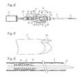
- FIG. 6shows an elevated cross-sectional view of the biopsy instrument.
- FIGS. 7 a , 7 b , 7 c and 7 dare schematic diagrams of the valve assembly and associated tubing for operating the biopsy instrument of FIG. 1 .
- FIG. 8shows a detailed view of the cutting cannula.
- FIG. 9illustrates details of the cutting cannula and adhesion probe.
- FIG. 1illustrates a biopsy instrument 1 which comprises an adhesion probe 2 , a cutting cannula 3 , and a housing 4 sized and shaped to form a convenient handle and also to house the components of the instrument.
- the housingfurther comprises a button interface 5 , detailed in FIG. 2 , which allows the user to control the device and which reports to the user the state of the device.
- the button interfacecomprises a sample button 6 which may be depressed by the user to initiate sampling operation of the device, a retract button 7 which may be depressed by the operator to initiate retraction of the cutting cannula after sampling, a ready light 8 which is operable by the device controller to indicate to the operator that the device is ready for use, a sample light 9 which is operable by the control system to indicate that the device is operating to core a biopsy sample from a patient, and an expended light 10 to indicate when the CO 2 liquid has been expended.
- Membrane switches, or any other form of input devicemay be used as input buttons.
- the indicator lightsmay be replaced with any form of visual, audible, or tactile indicator capable of providing several distinct signals to the user.
- FIG. 3is an isometric view of internal components of the biopsy instrument illustrated in FIG. 1 .
- the adhesion probe 2 and cutting cannula 3are operably connected to the various components illustrated in FIG. 3 .
- Coolantis supplied to the adhesion probe from the small portable liquid CO 2 canisters or whippets 11 .
- Canisters of N 2 0 (nitrous oxide), ethane, propane, methane or tetrafluoromethane (R14)may also be used. Because the device is designed to use the liquid cryogen, rather than the gaseous cryogen, within the canister, the canister is held in fixed relationship to the biopsy instrument, with the outlet pointing downward, establishing an up-and-down orientation for the device. In use, the canister which is disposed at a substantial angle relative to the adhesion probe is disposed in an inclined position when the adhesion probe is horizontally oriented.
- the biopsy instrumentincludes a coring mechanism that serves as both a translating mechanism and a rotating mechanism for the cannula.
- the translating mechanism and a rotating mechanismare provided in the form of a combined translating/coring mechanism which performs the rotating operation as it performs the longitudinal translation of the cannula that is required for coring.
- the combined translating/coring mechanismis comprised of a hydraulic actuator 12 and the various valves in valve block 13 and mechanical components described in more detail below.
- a computerized control systemis provided on a printed circuit board 14 .
- the control systemis powered by a 9 volt battery 15 or other suitable power source. The battery can be removed if needed to facilitate disposal.
- FIGS. 3 , 4 , 5 and 6show various views of the biopsy instrument, which is adapted for use with an adhesion probe 2 for securing a breast tumor during a biopsy or resection procedure.
- a suitable adhesion probeis described in Van Bladel, et al., Device for Biopsy of Tumors , U.S. Pat. No. 6,551,255 (Apr. 22, 2003), incorporated herein by reference.
- the adhesion probe 2comprises a long, slender yet rigid tube.
- a short rigid penetrating segment 2 dextends distally from the distal end of the rigid tube, and a coolant inlet tube passes through the rigid tube, extending to the distal end of the rigid tube, and terminating just proximal of the distal tip of the penetrating segment.
- the distal tip 2 tis beveled, and the bevel face is oriented to face upward relative to the device, and thus is radially aligned with the cryogen canister, so that it is oriented superficially, toward the skin of the patient, when in use.
- the cutting cannula 3is slidably disposed around the adhesion probe, longitudinally translated relative to the adhesion probe and adapted for insertion through a small incision in the skin, and may be inserted along the with the adhesion probe or over the adhesion probe.
- the cutting cannulamay be forced distally over the penetrating segment 2 d to core any tissue which is secured to the penetrating segment from any surrounding body tissue.
- the actuator 12includes a cylinder or piston chamber 16 , a proximal closure head 17 and a distal closure head 18 , a proximal piston 19 and a distal piston 20 , lead screw or jackscrew 21 disposed between the proximal and distal pistons, and an actuator rod 22 .
- the lead screwis bounded on both sides by the pistons 19 and 20 .
- the cylinder 16can be formed from the inner surface of the housing, or the housing may be integrally formed with the cylinder.
- the pistonsare disposed within the piston cylinder chamber, such that the pistons, although tightly fitting within the cylinder chamber, are capable of translating longitudinally along the cylinder. They may also be rotatable relative to the cylinder.
- the pistonsare attached to the cannula 3 , and are longitudinally fixed to the cannula, through the actuator 22 .
- the actuatormay be integrally formed with the cannula, and may, as illustrated, be formed of the proximal extent of the cutting cannula.
- the pistonsmay be rotatably fixed to the cannula, but the cannula may also be longitudinally fixed to the pistons while remaining freely rotatable relative to the pistons. The translation of the pistons distally and proximally through the cylinder is translated to the cannula.
- the actuator rod or proximal extent of the cannulamay extend from the proximal end of the housing, through a bore in the proximal piston and the distal piston, and through the lead screw 22 , or it may terminate proximally at the distal piston, or any point in between, so long as it is fixed to the pistons.)
- the adhesion probe and cannulaare coaxially disposed within the pistons, actuator rod and cylinder.
- the cannula rotating mechanismis comprised of a lead screw 22 (which also serves as the actuator rod) and a lead screw nut 23 .
- the lead screwis formed of a tube, with screw threads on the outside of the tube and a lumen passing through the tube.
- the lead screwis longitudinally fixed to the pistons, such that the lumen of the lead screw communicates with the respective piston bores.
- the actuator rod or proximal extent of the cannulamay pass through the lumen of the lead screw.
- the lead screw nutis adapted to receive the lead screw.
- the lead screwis screwed into and through the lead screw nut.
- the cannula 3is rotationally fixed into the lead screw, either directly or indirectly.
- the lead screwWhen the pistons are translated, the lead screw translates under operation of the pistons and rotates via translation of the lead screw through the lead screw nut.
- the lead screwcan have a pitch of 1 inch per revolution, such that for every inch of translation, the lead screw rotates one revolution. Because the lead screw is rotationally fixed to the cannula, the rotation of the lead screw is translated to the cannula.
- the cannula translating mechanismhas a retracted/proximal position and an extended/distal position.
- FIG. 4illustrates the translating mechanism in the retracted position, where the cannula 3 will not be engaged with the tumor.
- the distal pistonis positioned at the proximal end of the cylinder and the penetrating segment 2 d of the adhesion probe 2 is exposed, extending distally from the cannula.
- FIG. 5illustrates the translating mechanism in the advanced position, with the cannula translated distally over the penetrating segment 2 d of the adhesion probe, where it will engage and core a tumor secured to the penetrating segment. Comparison of FIGS.
- FIGS. 4 and 5illustrates the cooperative interaction between the proximal and distal pistons, the lead screw, and the cutting cannula.
- FIGS. 4 and 5also show the CO 2 canister 11 , the valve block 13 , the computerized control system 14 , the battery 15 , the motor 24 , and the gear box 25 , all within the housing 4 .
- the CO 2 canister 11is shown disposed within the vertically oriented canister housing (formed integrally with the housing 4 ) and is held in place by the screw-cap 26 .
- the outlet of the CO 2 canisteris jammed into the pierce pin connector 27 upon closure of the screw-cap, establishing a fluid pathway from the canister to the valve block.
- the CO 2 used in the probeexhausts from the proximal end 2 p of the adhesion probe, and thence through exhaust vent 28 in the device housing, shown in FIGS. 4 and 5 .
- a filter 29is disposed in the exhaust gas pathway to prevent cryogen from escaping (small bits of solid CO 2 , or droplets of liquid N 2 O, may be ejected from the proximal end of the adhesion probe).
- FIG. 6shows a top view of the biopsy instrument, in which the valve block 13 and gear motor 24 are more clearly visible.
- the main valve 41 , advance valve 46 and retract valve 51are connected through various tubes which direct fluid flow to the various components, as described in relation to FIGS. 7 a through 7 d .
- the motoris shown at the proximal end of the instrument, proximal of the valve block 13 .
- the motoris operably connected to the various valve stems (see FIGS. 7 a through 7 d ) through motor gear box 25 , jack screw 30 and the jack screw nut 31 (also referred to as a drive nut).
- the drive nutoperates directly on the main valve stem 42 , and operates the advance valve stem 51 through cam 32 , and operates on the retract valve stem 47 through cam 33 .
- Proximal movement of the jack screw nutresults in operation of cam 32 to impinge on advance valve stem 51 to open the advance valve an direct flow of high pressure liquid cryogen to the advance side of the cutter actuator piston, and further proximal movement of the jack screw nut results in rotation of cam 33 to impinge on retract valve stem 47 , pushing the retract valve stem into the retract valve to open the valve and direct flow to the retract side of the cutter actuator piston.
- a manifold 34is used to distribute liquid cryogen from the main valve to the various points in the system.
- Main valve outlet tube 58provides a fluid pathway from the main valve to the manifold, and the fluid is then distributed to the retract valve through retract valve supply tube 62 and to the advance valve through the advance valve supply tube 60 .
- the small wiper contact 35 on the drive nutinteracts with a corresponding trace on the printed circuit board which is fixed in predetermined position relative to the valve stem such that the wiper/trace combination may act as a limit switch to provide feedback to the computer control system as to the position of the drive nut and main valve stem.
- This trace and/or additional traces on the circuit boardcan be used as described below to provide feedback for control of the motor and drive nut.
- FIGS. 7 a through 7 dare schematic diagrams of the valve assembly and associated tubing for operating the biopsy instrument of FIG. 1 .
- the valve assemblycomprises the valve block 13 , which includes a main valve and two associated valves which have inlets aligned to the outlet of the main valve.
- the main valve 41comprises a main valve stem 42 , main valve outlet 43 , main valve inlet 44 and main reservoir 45 .
- the retract valve 46comprises a retract valve stem 47 , retract valve outlet 48 , retract valve inlet 49 and retract reservoir 50 .
- the advance valve 51comprises an advance valve stem 52 , advance valve outlet 53 , advance valve inlet 54 and advance reservoir 55 .
- the valvesare spring loaded plunger valves which are normally closed, such that movement of the plunger into the valves opens the valves.
- the valvesmay comprise a ball which is forced against the valve seat, or a typical plunger valve with a seal positively fixed to the plunger, as shown.
- the inlets of both the retract valve and the advance valveare fitted with check valves 56 and 57 , which may be spring biased ball check valves or any other type of check valve.
- FIG. 7 ashows the system in its initial condition, with all three valves closed, the cutting cannula in the retracted position, and the adhesion probe extending distally from the distal extent of the cutting cannula.
- the CO 2 canisteris filled with liquid CO 2 , and is in fluid communication with the inlet of main valve 41 .
- the motor(item 24 in FIG. 6 ) operates through linkages to drive the jack screw nut forward, thus driving the main valve stem 42 forward, thereby opening the main valve, as shown in FIG. 7 b .
- the main valveis driven forward from a home position until the electrically conductive wiper that is mounted to the drive nut loses contact with traces on the printed circuit board (any other form of contact switch, proximity switch, encoder or sensor may be used to sense the position of the main valve stem (and, thus, the state of the valve)).
- the motorstops in this position for a period (the dwell time) which may be predetermined or calculated by the computerized control system.
- the dwell timeis calculated by the control system based on the time required for the conductive wiper to traverse the trances on the printed circuit board. This dynamic calculation of the dwell time allows the computerized control system to automatically compensate for variations in the sped of the valve stem travel due to motor characteristics, friction in the system, and battery voltage.
- liquid C0 2flows through the main valve outlet 43 to the coolant supply tubing 58 that is connected to the adhesion probe 2 .
- the sample light 9is flashed while cryogen is flowing to the adhesion probe to indicate to the operator that the device is operating in cooling mode.
- the cryogen exits the port inside the adhesion probe 2the temperature of the penetrating segment 2 d drops. While liquid is flowing to the adhesion probe, liquid is also routed to charge the advance reservoir 55 and retract reservoir 50 through the advance valve inlet 54 and the retract valve inlet 49 .
- the size of the reservoirsare calculated to provide a set pressure inside the cylinder once all of the valves open and the liquid CO 2 is turned to vapor with an expansion ratio of 400:1 or more (compensating for end state gas temperature).
- the motoris reversed. As the main valve stem 42 moves backward, as shown in FIG. 7 c , the main valve closes. The motor continues in reverse operation to drive the drive nut backward. At this point, the main valve is fully closed and the cooling flow to the adhesion probe ceases.
- the jack screw nut 31encounters a cam 32 and forces the cam to pivot forward and forces advance valve stem 52 forward to open the advance valve 51 . This allows fluid to flow through the pressure tubing 60 into the advance side 61 of the piston cylinder 16 which drives the cutting cannula forward. As the cannula translates, the cannula rotates under operation of the lead screw and lead screw nut assembly illustrated in FIGS. 4 and 5 .
- the motorcontinues in reverse operation to draw the drive nut backward until the wiper encounters a second contact (the second contact is located on the circuit board or other fixed structure located above the drive nut) and stops.
- the cutting cannulais fully extended over the adhesion probe, and has excised any tissue adhered to the distal segment of the adhesion probe.
- the time required for this complete stick freeze/advance cycleis preferably less than 10 seconds, and is about 4 seconds using the embodiments illustrated.
- the control systemilluminates the sample light 9 on the input pad continuously after advancing the cutter, to indicate to the operator that the coring operation is complete.
- electromechanical valve actuators described above in relation to FIGS. 6 and 7 a through 7 dprovide for fairly simple, compact and quick actuation of the valves in the high pressure system
- other electromechanical valve actuatorsmay be used.
- Each valvemay be driven by a different solenoid actuator or a different motor, and each actuator or motor may be operated by the control system programmed to provide the valve timing described above.
- Other valve actuatorsincluding pneumatic actuators (driven by the high pressure cryogen stored in the canister), shape memory actuators (heated by the battery, as controlled by the control system), and any other valve actuating means may be used.
- the embodiment described above, however,is compact, sufficiently powerful to operate against the high pressures of the cryogen, and inexpensive.
- the control systemoperates the motor continues to operate, in reverse, to move the drive nut backwards until a second cam 33 is encountered by the jack screw nut 31 .
- This second campivots forward and opens the retract valve 46 , as shown in FIG. 7 d .
- the tissue excised from the bodyis then exposed, and is readily removed from the distal segment of the adhesion probe.
- the advance side 61 of the piston cylinder 16must be evacuated prior to application of high pressure fluid to the retract side, to prevent hydraulic/pneumatic binding of the piston.
- the advance side of the piston cylindermay be vented in any convenient manner.
- the valve bodiescomprise cylinders 65 with end caps 66 .
- the threading of end cap on the advance valveis machined so that it is slightly loose (or gas valve threads are used, and the cap is not completely seated) and allows slight leakage of the cryogen from the valve body reservoir.
- the retract cylinderis vented in the same manner. Vented may be accomplished with small apertures in the end caps or valve bodies in similar fashion.
- the amount of time in which coolant is flowingdepends on desired temperature of adhesion probe. Final temperature of about ⁇ 3° to ⁇ 20° C. is desired for biopsy, while a final temperature below ⁇ 30° C. is desired for cryo-preservation.
- a thermocouplemay be embedded in the adhesion probe so that the device may be temperature controlled rather than time controlled. This will compensate for differences in device or tissue thermal loading, or the difference between the first shot of liquid CO 2 and the last as the device cools down, and for variations in the speed of the valve stem travel which may result from variations in the battery. For a standard biopsy with a fully charged battery, the dwell time after the main valve is fully open is about 0.5 to 2.0 seconds.
- the valveis open, then, for about 5 seconds, which includes the dwell time and the time in which the valve stem is moving (and the valve is open).
- CO 2 flow of 0.05 and 1.25 grams per 5 second cycle (0.01 to 0.25 grams per second)provides adequate cooling for biopsy, which requires cooling sufficient to adhere the probe to the tissue, and preferable does not result in extensive freezing.
- This flowis appropriate in embodiments in which the adhesion probe outer tube has an outer diameter of 0.0.43 inches and an inner diameter of 0.029 inches (a 19 gauge hypo tube), and the adhesion probe inner tube has an outer diameter of 0.020 inches and an inner diameter of 0.007 inches (28 gauge).
- the flow ratemay be adjusted as necessary with different constructions of the device.
- the motorAfter moving the jack screw nut back a set distance, the motor is stopped and then driven forward until the jack screw nut is driven to its home position.
- the control systemchecks the battery voltage and verifies that the number of cycles used is within the capacity of the CO 2 canister. Conveniently sized canisters hold enough liquid CO 2 to supply the system for about 7 coring operations. Twelve to sixteen grams of liquid are sufficient in a canister filled to 75% density. If there are any cycles left, the ready light 8 illuminates. If not, the expended light 10 illuminates and the system is software disabled. The system will not operate if it has already counted 7 operating cycles (this limit is somewhat arbitrary, chosen to provide ample cycles for a single patient use, and it may be adjusted as manufacturers and doctors gain experience with the device).
- FIG. 8shows a detailed view of the cannula cutter.
- the cutting edgeis provided in the form of a scalloped bevel, formed by multi-axis machining.
- the cutting edge 3 dhas several distally extending, longitudinally rounded protrusions which are provided with a sharp longitudinally oriented bevel, with the cutting edge toward the inner wall of the cannula, and the bevel extending proximally toward the outer wall, and the circumference of the bevel following a scalloped or sinusoidal curve relative to the longitude of the cannula.
- a beveled tip with three such longitudinally rounded protrusionsworks well on breast tissue.
- FIG. 9illustrates details of the cutting cannula and adhesion probe.
- the adhesion probe 2 and cutting cannula 3 of the prior figuresare shown in cross section.
- a ferrule 72is fitted coaxially over the adhesion probe, between the adhesion probe and the cutting cannula.
- the ferruleis fixed to the adhesion probe, and has an outer diameter closely matching the inner diameter of the cutting cannula, and is used to provide the proximal segment of the adhesion probe with a larger outer diameter than the distal segment.
- a trocar-type blade or tapered coneprovides the transition from the outer diameter of the ferrule to the distally extending penetrating segment 2 d is formed in.
- One or more ring seals 73are disposed between the ferrule and the cutting cannula, and may be secured within annular grooves within the ferrule, as shown.
- the ring sealsserve to prevent body fluids seeping into the clearance between the adhesion probe/ferrule and the cutting cannula and freezing during operation of the device, and this eliminates any interference with cannula translation that may result.
- valve stem travel timeis calculated by dividing the distance the valve must travel (which depends on the construction of the device) by the measured speed of the valve stem (which corresponds to the speed of the drive nut).
- the speed of the drive nutis determined by measuring the time required to travel past the trace, or to move from one trace to another trace, given that the trace(s) are fixed relative to the drive nut wiper and the length of the trace (or the distance between the traces) is known.
- the ready light 8 on the button interface 5illuminates.
- the usertypically a surgeon or radiologist, inserts the distal tip of the adhesion probe into a tumor or other suspect mass within the body of a patient.
- the userdepresses the sample button on the input pad, and the system initiations the cooling and coring operation described above in relation to FIGS. 7 a through 7 c .
- the control systemoperates the sample light continuously to indicate to the operator that the sample has been cored from the patient. The user than removes the probe from the patient, and depresses the retract button on the input pad.
- control systeminitiates the retraction operation described above in relation to FIG. 7 d .
- the cored tissue samplemay then be removed from the distal tip, and, if the user desires to take more samples, the adhesion probe can be re-inserted into the body.
- the systemis provided with safety features to prevent over-pressurization, initiation of sampling with a partially discharged device, etc.
- the average pressure inside the CO 2 canister at room temperatureis 850 psi. Extreme ambient heating may result in canister pressure of 3 kpsi.
- the burst pressure of the canisteris 10 kpsi, but there is no need to construct the entire probe to withstand such high pressure.
- a burst disk 74(shown throughout the figures) may be placed in line with the main valve so that it will vent when the pressure is higher than 3 kpsi. Any other suitable pressure relief means may be used.
- the canistermay self discharge, so that it no longer hold enough gas for a full compliment of sampling procedures, or doctors may inadvertently attempt to use a device on a patient after it has already been used on another patient.
- the control systemis programmed to exhaust the probe after a predetermined time period, such as by driving the drive nut forward to vent out any remaining gas.
- the deviceis provided as a disposable device, such that it cannot be recharged and re-used. This is accomplished with appropriate programming of the computerized control system within the device. The device could be sent back for re-processing, however, in which case the circuitry, internal components and housing can be recycled into new devices with sterile probe and cutter assemblies, and the control system could be reset to allow another set of operating cycles.
Landscapes
- Health & Medical Sciences (AREA)
- Life Sciences & Earth Sciences (AREA)
- Surgery (AREA)
- Animal Behavior & Ethology (AREA)
- Biomedical Technology (AREA)
- Heart & Thoracic Surgery (AREA)
- Medical Informatics (AREA)
- Molecular Biology (AREA)
- Pathology (AREA)
- Engineering & Computer Science (AREA)
- General Health & Medical Sciences (AREA)
- Public Health (AREA)
- Veterinary Medicine (AREA)
- Surgical Instruments (AREA)
- Medicines Containing Antibodies Or Antigens For Use As Internal Diagnostic Agents (AREA)
- External Artificial Organs (AREA)
Abstract
Description
valve cycle time=(desired cryogen flow cycle time)+(valve stem travel time to initiate flow);
where
desired cryogen flow cycle time=valve stem travel time after valve opening+dwell time.
Claims (5)
Priority Applications (1)
| Application Number | Priority Date | Filing Date | Title |
|---|---|---|---|
| US12/611,085US8231545B2 (en) | 2004-02-12 | 2009-11-02 | Rotational core biopsy device with liquid cryogen adhesion probe |
Applications Claiming Priority (3)
| Application Number | Priority Date | Filing Date | Title |
|---|---|---|---|
| US10/779,520US7402140B2 (en) | 2004-02-12 | 2004-02-12 | Rotational core biopsy device with liquid cryogen adhesion probe |
| US12/177,470US7611475B2 (en) | 2004-02-12 | 2008-07-22 | Rotational core biopsy device with liquid cryogen adhesion probe |
| US12/611,085US8231545B2 (en) | 2004-02-12 | 2009-11-02 | Rotational core biopsy device with liquid cryogen adhesion probe |
Related Parent Applications (1)
| Application Number | Title | Priority Date | Filing Date |
|---|---|---|---|
| US12/177,470ContinuationUS7611475B2 (en) | 2004-02-12 | 2008-07-22 | Rotational core biopsy device with liquid cryogen adhesion probe |
Publications (2)
| Publication Number | Publication Date |
|---|---|
| US20100049087A1 US20100049087A1 (en) | 2010-02-25 |
| US8231545B2true US8231545B2 (en) | 2012-07-31 |
Family
ID=34838404
Family Applications (3)
| Application Number | Title | Priority Date | Filing Date |
|---|---|---|---|
| US10/779,520Active2026-09-13US7402140B2 (en) | 2004-02-12 | 2004-02-12 | Rotational core biopsy device with liquid cryogen adhesion probe |
| US12/177,470Expired - LifetimeUS7611475B2 (en) | 2004-02-12 | 2008-07-22 | Rotational core biopsy device with liquid cryogen adhesion probe |
| US12/611,085Expired - Fee RelatedUS8231545B2 (en) | 2004-02-12 | 2009-11-02 | Rotational core biopsy device with liquid cryogen adhesion probe |
Family Applications Before (2)
| Application Number | Title | Priority Date | Filing Date |
|---|---|---|---|
| US10/779,520Active2026-09-13US7402140B2 (en) | 2004-02-12 | 2004-02-12 | Rotational core biopsy device with liquid cryogen adhesion probe |
| US12/177,470Expired - LifetimeUS7611475B2 (en) | 2004-02-12 | 2008-07-22 | Rotational core biopsy device with liquid cryogen adhesion probe |
Country Status (8)
| Country | Link |
|---|---|
| US (3) | US7402140B2 (en) |
| EP (1) | EP1740101A4 (en) |
| JP (1) | JP2007521924A (en) |
| CN (1) | CN100571649C (en) |
| AU (1) | AU2005214067A1 (en) |
| BR (1) | BRPI0507659A (en) |
| CA (1) | CA2555416A1 (en) |
| WO (1) | WO2005079321A2 (en) |
Cited By (2)
| Publication number | Priority date | Publication date | Assignee | Title |
|---|---|---|---|---|
| US10610205B2 (en) | 2014-05-15 | 2020-04-07 | Devicor Medical Products, Inc. | Biopsy device |
| US11096676B2 (en) | 2016-11-21 | 2021-08-24 | C.R. Bard, Inc. | Biopsy device having a hydraulic drive assembly |
Families Citing this family (127)
| Publication number | Priority date | Publication date | Assignee | Title |
|---|---|---|---|---|
| EP1524940B1 (en) | 2002-03-19 | 2011-08-24 | Bard Dublin ITC Limited | Biopsy device and biopsy needle module that can be inserted into the biopsy device |
| US8109885B2 (en) | 2002-03-19 | 2012-02-07 | C. R. Bard, Inc. | Biopsy device for removing tissue specimens using a vacuum |
| US8668698B2 (en) | 2002-05-31 | 2014-03-11 | Vidacare Corporation | Assembly for coupling powered driver with intraosseous device |
| US9072543B2 (en) | 2002-05-31 | 2015-07-07 | Vidacare LLC | Vascular access kits and methods |
| US9314228B2 (en) | 2002-05-31 | 2016-04-19 | Vidacare LLC | Apparatus and method for accessing the bone marrow |
| US7951089B2 (en) | 2002-05-31 | 2011-05-31 | Vidacare Corporation | Apparatus and methods to harvest bone and bone marrow |
| US7850620B2 (en) | 2002-05-31 | 2010-12-14 | Vidacare Corporation | Biopsy devices and related methods |
| US9451968B2 (en) | 2002-05-31 | 2016-09-27 | Vidacare LLC | Powered drivers, intraosseous devices and methods to access bone marrow |
| US10973545B2 (en) | 2002-05-31 | 2021-04-13 | Teleflex Life Sciences Limited | Powered drivers, intraosseous devices and methods to access bone marrow |
| US8690791B2 (en) | 2002-05-31 | 2014-04-08 | Vidacare Corporation | Apparatus and method to access the bone marrow |
| US7811260B2 (en) | 2002-05-31 | 2010-10-12 | Vidacare Corporation | Apparatus and method to inject fluids into bone marrow and other target sites |
| EP2039298B1 (en) | 2002-05-31 | 2017-10-25 | Vidacare LLC | Apparatus to access bone marrow |
| US10973532B2 (en) | 2002-05-31 | 2021-04-13 | Teleflex Life Sciences Limited | Powered drivers, intraosseous devices and methods to access bone marrow |
| US8142365B2 (en) | 2002-05-31 | 2012-03-27 | Vidacare Corporation | Apparatus and method for accessing the bone marrow of the sternum |
| US8641715B2 (en) | 2002-05-31 | 2014-02-04 | Vidacare Corporation | Manual intraosseous device |
| US11337728B2 (en) | 2002-05-31 | 2022-05-24 | Teleflex Life Sciences Limited | Powered drivers, intraosseous devices and methods to access bone marrow |
| US20070049945A1 (en) | 2002-05-31 | 2007-03-01 | Miller Larry J | Apparatus and methods to install, support and/or monitor performance of intraosseous devices |
| US11298202B2 (en) | 2002-05-31 | 2022-04-12 | Teleflex Life Sciences Limited | Biopsy devices and related methods |
| AU2002368364A1 (en)* | 2002-11-18 | 2004-06-15 | N.V. H And O Equipments | Instrument for cryogenic treatments in the medical, paramedical and cosmetic field |
| DE10314240B4 (en) | 2003-03-29 | 2025-05-28 | Bard Dublin Itc Ltd. | Pressure generation unit |
| US9504477B2 (en) | 2003-05-30 | 2016-11-29 | Vidacare LLC | Powered driver |
| CN101536926B (en) | 2004-01-26 | 2012-07-18 | 维达保健公司 | Manual interosseous device |
| US7815642B2 (en) | 2004-01-26 | 2010-10-19 | Vidacare Corporation | Impact-driven intraosseous needle |
| US7402140B2 (en)* | 2004-02-12 | 2008-07-22 | Sanarus Medical, Inc. | Rotational core biopsy device with liquid cryogen adhesion probe |
| USD569515S1 (en)* | 2004-02-12 | 2008-05-20 | Sanarus Medical, Inc. | Biopsy device |
| US8932233B2 (en) | 2004-05-21 | 2015-01-13 | Devicor Medical Products, Inc. | MRI biopsy device |
| JP4814229B2 (en) | 2004-07-09 | 2011-11-16 | バード ペリフェラル ヴァスキュラー インコーポレイテッド | Transport device for biopsy device |
| US8998848B2 (en) | 2004-11-12 | 2015-04-07 | Vidacare LLC | Intraosseous device and methods for accessing bone marrow in the sternum and other target areas |
| US7604631B2 (en)* | 2004-12-15 | 2009-10-20 | Boston Scientific Scimed, Inc. | Efficient controlled cryogenic fluid delivery into a balloon catheter and other treatment devices |
| US7517321B2 (en) | 2005-01-31 | 2009-04-14 | C. R. Bard, Inc. | Quick cycle biopsy system |
| US7850683B2 (en) | 2005-05-20 | 2010-12-14 | Myoscience, Inc. | Subdermal cryogenic remodeling of muscles, nerves, connective tissue, and/or adipose tissue (fat) |
| US7713266B2 (en)* | 2005-05-20 | 2010-05-11 | Myoscience, Inc. | Subdermal cryogenic remodeling of muscles, nerves, connective tissue, and/or adipose tissue (fat) |
| US7867173B2 (en) | 2005-08-05 | 2011-01-11 | Devicor Medical Products, Inc. | Biopsy device with replaceable probe and incorporating vibration insertion assist and static vacuum source sample stacking retrieval |
| US7854707B2 (en) | 2005-08-05 | 2010-12-21 | Devicor Medical Products, Inc. | Tissue sample revolver drum biopsy device |
| USRE46135E1 (en) | 2005-08-05 | 2016-09-06 | Devicor Medical Products, Inc. | Vacuum syringe assisted biopsy device |
| JP4991723B2 (en) | 2005-08-10 | 2012-08-01 | シー・アール・バード・インコーポレーテッド | Single insertion multiple sampling biopsy device with integrated marker |
| ES2539578T3 (en) | 2005-08-10 | 2015-07-02 | C.R. Bard, Inc. | Multi-sample biopsy device and single insert with various transport systems |
| EP1921998B8 (en) | 2005-08-10 | 2021-07-07 | C.R.Bard, Inc. | Single-insertion, multiple sampling biopsy device with linear drive |
| USD569516S1 (en)* | 2005-08-23 | 2008-05-20 | Sanarus Medical, Inc. | Biopsy device |
| US20070055173A1 (en)* | 2005-08-23 | 2007-03-08 | Sanarus Medical, Inc. | Rotational core biopsy device with liquid cryogen adhesion probe |
| US20070156125A1 (en)* | 2005-12-30 | 2007-07-05 | Russell Delonzor | Encodable cryogenic device |
| US20070191732A1 (en)* | 2006-02-10 | 2007-08-16 | Voegele James W | Cryogenic probe |
| US10363092B2 (en) | 2006-03-24 | 2019-07-30 | Neuwave Medical, Inc. | Transmission line with heat transfer ability |
| US10376314B2 (en) | 2006-07-14 | 2019-08-13 | Neuwave Medical, Inc. | Energy delivery systems and uses thereof |
| US11389235B2 (en) | 2006-07-14 | 2022-07-19 | Neuwave Medical, Inc. | Energy delivery systems and uses thereof |
| EP3417792B1 (en) | 2006-08-21 | 2022-03-02 | C. R. Bard, Inc. | Self-contained handheld biopsy needle |
| US8944069B2 (en) | 2006-09-12 | 2015-02-03 | Vidacare Corporation | Assemblies for coupling intraosseous (IO) devices to powered drivers |
| EP2073728B1 (en) | 2006-09-12 | 2018-11-07 | Teleflex Medical Devices S.à.r.l. | Biopsy device |
| EP2068743B1 (en) | 2006-09-12 | 2017-03-15 | Vidacare LLC | Medical procedures trays, kits and related methods |
| EP3189787B1 (en) | 2006-09-12 | 2019-01-09 | Teleflex Medical Devices S.à.r.l. | Medical procedures trays and related methods |
| SI2086418T1 (en) | 2006-10-06 | 2011-05-31 | Bard Peripheral Vascular Inc | Tissue handling system with reduced operator exposure |
| US8262586B2 (en) | 2006-10-24 | 2012-09-11 | C. R. Bard, Inc. | Large sample low aspect ratio biopsy needle |
| US8974410B2 (en) | 2006-10-30 | 2015-03-10 | Vidacare LLC | Apparatus and methods to communicate fluids and/or support intraosseous devices |
| US8480595B2 (en) | 2006-12-13 | 2013-07-09 | Devicor Medical Products, Inc. | Biopsy device with motorized needle cocking |
| DE102007020582A1 (en)* | 2006-12-19 | 2008-06-26 | Erbe Elektromedizin Gmbh | A cryosurgical instrument and method for separating a tissue sample from surrounding tissue of a biological tissue to be treated |
| US9254162B2 (en) | 2006-12-21 | 2016-02-09 | Myoscience, Inc. | Dermal and transdermal cryogenic microprobe systems |
| US8409185B2 (en)* | 2007-02-16 | 2013-04-02 | Myoscience, Inc. | Replaceable and/or easily removable needle systems for dermal and transdermal cryogenic remodeling |
| DE102008026635B4 (en)* | 2007-06-26 | 2010-10-28 | Erbe Elektromedizin Gmbh | Kryobiopsiesonde |
| US8380299B2 (en)* | 2007-07-30 | 2013-02-19 | Nuvue Therapeutics, Inc. | Fluid flowing device and method for tissue diagnosis or therapy |
| WO2009065061A1 (en) | 2007-11-14 | 2009-05-22 | Myoscience, Inc. | Pain management using cryogenic remodeling |
| US8241225B2 (en) | 2007-12-20 | 2012-08-14 | C. R. Bard, Inc. | Biopsy device |
| US7854706B2 (en) | 2007-12-27 | 2010-12-21 | Devicor Medical Products, Inc. | Clutch and valving system for tetherless biopsy device |
| US20100152610A1 (en)* | 2008-12-16 | 2010-06-17 | Parihar Shailendra K | Hand Actuated Tetherless Biopsy Device with Pistol Grip |
| US8574167B2 (en) | 2008-12-16 | 2013-11-05 | Devicor Medical Products, Inc. | Needle for biopsy device |
| US8622927B2 (en) | 2008-12-18 | 2014-01-07 | Devicor Medical Products, Inc. | Mechanical tissue sample holder indexing device |
| JP5642087B2 (en) | 2008-12-22 | 2014-12-17 | ミオサイエンス インコーポレーティッド | Integrated cryosurgery system with refrigerant and power supply |
| WO2010107424A1 (en) | 2009-03-16 | 2010-09-23 | C.R. Bard, Inc. | Biopsy device having rotational cutting |
| AU2009344276B2 (en) | 2009-04-15 | 2014-06-05 | C.R. Bard, Inc. | Biopsy apparatus having integrated fluid management |
| WO2010124109A1 (en) | 2009-04-22 | 2010-10-28 | Nuvue Therapeutics, Inc. | Fluid flowing device and method for tissue diagnosis or therapy |
| US20100274236A1 (en)* | 2009-04-23 | 2010-10-28 | Krimsky William S | Apparatuses and methods for applying a cryogenic effect to tissue and cutting tissue |
| US8888768B2 (en)* | 2009-04-30 | 2014-11-18 | Cryomedix, Llc | Cryoablation system having docking station for charging cryogen containers and related method |
| US8206316B2 (en) | 2009-06-12 | 2012-06-26 | Devicor Medical Products, Inc. | Tetherless biopsy device with reusable portion |
| EP3549544B1 (en)* | 2009-07-28 | 2021-01-06 | Neuwave Medical, Inc. | DEVICE FOR ABLATION |
| US9173641B2 (en) | 2009-08-12 | 2015-11-03 | C. R. Bard, Inc. | Biopsy apparatus having integrated thumbwheel mechanism for manual rotation of biopsy cannula |
| US8283890B2 (en) | 2009-09-25 | 2012-10-09 | Bard Peripheral Vascular, Inc. | Charging station for battery powered biopsy apparatus |
| US8485989B2 (en) | 2009-09-01 | 2013-07-16 | Bard Peripheral Vascular, Inc. | Biopsy apparatus having a tissue sample retrieval mechanism |
| US8430824B2 (en) | 2009-10-29 | 2013-04-30 | Bard Peripheral Vascular, Inc. | Biopsy driver assembly having a control circuit for conserving battery power |
| US8597206B2 (en) | 2009-10-12 | 2013-12-03 | Bard Peripheral Vascular, Inc. | Biopsy probe assembly having a mechanism to prevent misalignment of components prior to installation |
| EP2493390B1 (en)* | 2009-10-30 | 2014-12-31 | Cook Medical Technologies LLC | System for performing a full thickness tissue biopsy |
| WO2011104692A2 (en)* | 2010-02-25 | 2011-09-01 | Robin Medical Inc. | Cryogenic biopsy system and method |
| US20110224576A1 (en)* | 2010-03-12 | 2011-09-15 | Biotex, Inc. | Methods and devices for tissue collection and analysis |
| JP5144833B2 (en)* | 2010-04-08 | 2013-02-13 | 学校法人 久留米大学 | Suction puncture device |
| ES2856026T3 (en) | 2010-05-03 | 2021-09-27 | Neuwave Medical Inc | Power supply systems |
| CN103118613A (en) | 2010-08-26 | 2013-05-22 | 克莱米迪克斯有限责任公司 | Cryoablation balloon catheter and related method |
| EP2632372A4 (en) | 2010-10-27 | 2015-04-01 | Cryomedix Llc | Cryoablation apparatus with enhanced heat exchange area and related method |
| EP2670328B1 (en) | 2011-02-01 | 2019-10-16 | Channel Medsystems, Inc. | Apparatus for cyrogenic treatment of a body cavity or lumen |
| US9314568B2 (en)* | 2011-02-11 | 2016-04-19 | Lifecell Corporation | Devices and methods for tissue transfer |
| US8657760B2 (en)* | 2011-03-04 | 2014-02-25 | Cook Medical Technologies Llc | Ergonomic biopsy instrument |
| US9192438B2 (en) | 2011-12-21 | 2015-11-24 | Neuwave Medical, Inc. | Energy delivery systems and uses thereof |
| CN104159534B (en) | 2012-01-13 | 2017-02-22 | 肌肉科技股份有限公司 | Skin protection for subdermal cryogenic remodeling for cosmetic and other treatments |
| WO2013106860A1 (en) | 2012-01-13 | 2013-07-18 | Myoscience, Inc. | Cryogenic probe filtration system |
| EP2802279B1 (en) | 2012-01-13 | 2017-08-16 | Myoscience, Inc. | Cryogenic needle with freeze zone regulation |
| EP2804535B1 (en) | 2012-01-16 | 2016-11-23 | Coloplast A/S | Device for taking at least one sample of tissue |
| US9017318B2 (en) | 2012-01-20 | 2015-04-28 | Myoscience, Inc. | Cryogenic probe system and method |
| EP2838435B1 (en) | 2012-04-16 | 2020-03-25 | Hathaway, Jeff M. | Biopsy device |
| ES2924635T3 (en) | 2012-11-21 | 2022-10-10 | Bard Inc C R | Core needle biopsy device |
| USD735332S1 (en) | 2013-03-06 | 2015-07-28 | C. R. Bard, Inc. | Biopsy device |
| USD737440S1 (en) | 2013-03-07 | 2015-08-25 | C. R. Bard, Inc. | Biopsy device |
| WO2014146127A1 (en) | 2013-03-15 | 2014-09-18 | Myoscience, Inc. | Methods and systems for treatment of spasticity |
| US9615816B2 (en)* | 2013-03-15 | 2017-04-11 | Vidacare LLC | Drivers and drive systems |
| US9295512B2 (en) | 2013-03-15 | 2016-03-29 | Myoscience, Inc. | Methods and devices for pain management |
| WO2014146126A1 (en) | 2013-03-15 | 2014-09-18 | Myoscience, Inc. | Cryogenic blunt dissection methods and devices |
| US9610112B2 (en) | 2013-03-15 | 2017-04-04 | Myoscience, Inc. | Cryogenic enhancement of joint function, alleviation of joint stiffness and/or alleviation of pain associated with osteoarthritis |
| CA2902221A1 (en) | 2013-03-20 | 2014-09-25 | Bard Peripheral Vascular, Inc. | Biopsy device |
| USD735333S1 (en) | 2013-06-26 | 2015-07-28 | C. R. Bard, Inc. | Biopsy device |
| US10130409B2 (en) | 2013-11-05 | 2018-11-20 | Myoscience, Inc. | Secure cryosurgical treatment system |
| ES2726985T3 (en) | 2013-11-05 | 2019-10-11 | Bard Inc C R | Biopsy device that has integrated vacuum |
| US10610279B2 (en)* | 2014-04-10 | 2020-04-07 | Channel Medsystems, Inc. | Apparatus and methods for regulating cryogenic treatment |
| US11020098B2 (en)* | 2014-09-09 | 2021-06-01 | Boston Scientific Scimed, Inc. | Methods, systems and devices for cryogenic biopsy |
| JP6518784B2 (en)* | 2015-03-26 | 2019-05-22 | スパイレーション インコーポレイテッド ディー ビー エイ オリンパス レスピラトリー アメリカ | Apparatus for generating a local vacuum at the distal end of a sampling device |
| WO2016178656A1 (en) | 2015-05-01 | 2016-11-10 | C. R. Bard, Inc. | Biopsy device |
| CN113367788B (en) | 2015-10-26 | 2024-09-06 | 纽韦弗医疗设备公司 | Energy delivery systems and uses thereof |
| CN105505753B (en)* | 2016-01-20 | 2018-04-17 | 中国科学院广州生物医药与健康研究院 | A kind of cell obtains pin |
| US10531917B2 (en) | 2016-04-15 | 2020-01-14 | Neuwave Medical, Inc. | Systems and methods for energy delivery |
| EP4349396A3 (en) | 2016-05-13 | 2024-05-01 | Pacira CryoTech, Inc. | Systems for locating and treating with cold therapy |
| US11793498B2 (en) | 2017-05-19 | 2023-10-24 | Merit Medical Systems, Inc. | Biopsy needle devices and methods of use |
| US11844500B2 (en) | 2017-05-19 | 2023-12-19 | Merit Medical Systems, Inc. | Semi-automatic biopsy needle device and methods of use |
| US11116483B2 (en) | 2017-05-19 | 2021-09-14 | Merit Medical Systems, Inc. | Rotating biopsy needle |
| EP3709918B1 (en) | 2017-11-15 | 2025-06-18 | Pacira CryoTech, Inc. | Integrated cold therapy and electrical stimulation systems for locating and treating nerves |
| US11672596B2 (en) | 2018-02-26 | 2023-06-13 | Neuwave Medical, Inc. | Energy delivery devices with flexible and adjustable tips |
| WO2020086829A1 (en)* | 2018-10-26 | 2020-04-30 | University Of Washington | Tissue sample coring system |
| US11832879B2 (en) | 2019-03-08 | 2023-12-05 | Neuwave Medical, Inc. | Systems and methods for energy delivery |
| US12295556B2 (en) | 2019-09-27 | 2025-05-13 | Merit Medical Systems, Inc. | Rotation biopsy system and handle |
| US12150627B2 (en) | 2019-12-11 | 2024-11-26 | Merit Medical Systems, Inc. | Bone biopsy device and related methods |
| CN114376625A (en)* | 2022-01-14 | 2022-04-22 | 上海立升医疗科技有限公司 | Biopsy data visualization system and biopsy device |
| CN114159105B (en)* | 2022-01-14 | 2024-09-03 | 赛恩医疗科技(连云港)有限公司 | Continuous low-temperature biopsy safety air supply system and low-temperature biopsy device |
| CN116650030A (en)* | 2023-05-22 | 2023-08-29 | 赛昂国际医疗技术江苏有限公司 | Rotary-cut biopsy needle and cold-adhesion core biopsy needle assembly |
Citations (26)
| Publication number | Priority date | Publication date | Assignee | Title |
|---|---|---|---|---|
| US4644951A (en) | 1985-09-16 | 1987-02-24 | Concept, Inc. | Vacuum sleeve for a surgical appliance |
| US5027827A (en) | 1990-03-28 | 1991-07-02 | Cody Michael P | Vacuum biopsy apparatus |
| US5056532A (en) | 1989-07-25 | 1991-10-15 | Medtronic, Inc. | Esophageal pacing lead |
| US5056523A (en) | 1989-11-22 | 1991-10-15 | Board Of Regents, The University Of Texas System | Precision breast lesion localizer |
| US5133360A (en) | 1991-03-07 | 1992-07-28 | Spears Colin P | Spears retriever |
| US5234000A (en) | 1992-09-25 | 1993-08-10 | Hakky Said I | Automatic biopsy device housing a plurality of stylets |
| US5353804A (en) | 1990-09-18 | 1994-10-11 | Peb Biopsy Corporation | Method and device for percutaneous exisional breast biopsy |
| WO1997020504A1 (en) | 1995-12-06 | 1997-06-12 | Biopsys Medical, Inc. | Control system and method for automated biopsy device |
| US5649547A (en) | 1994-03-24 | 1997-07-22 | Biopsys Medical, Inc. | Methods and devices for automated biopsy and collection of soft tissue |
| WO1998006346A1 (en) | 1996-08-12 | 1998-02-19 | Biopsys Medical, Inc. | Apparatus and method for marking tissue |
| WO1998008441A1 (en) | 1996-08-29 | 1998-03-05 | Ethicon Endo-Surgery | Methods and devices for collection of soft tissue |
| US5775333A (en) | 1994-03-24 | 1998-07-07 | Ethicon Endo-Surgery, Inc. | Apparatus for automated biopsy and collection of soft tissue |
| US5833685A (en) | 1994-03-15 | 1998-11-10 | Tortal; Proserfina R. | Cryosurgical technique and devices |
| US5868673A (en) | 1995-03-28 | 1999-02-09 | Sonometrics Corporation | System for carrying out surgery, biopsy and ablation of a tumor or other physical anomaly |
| US5913857A (en) | 1996-08-29 | 1999-06-22 | Ethicon End0-Surgery, Inc. | Methods and devices for collection of soft tissue |
| US5944673A (en) | 1998-05-14 | 1999-08-31 | Ethicon Endo-Surgery, Inc. | Biopsy instrument with multi-port needle |
| WO1999044506A1 (en) | 1998-03-03 | 1999-09-10 | Senorx, Inc. | Breast biopsy system and method |
| US5964716A (en) | 1998-05-14 | 1999-10-12 | Ethicon Endo-Surgery, Inc. | Method of use for a multi-port biopsy instrument |
| US6007497A (en) | 1998-06-30 | 1999-12-28 | Ethicon Endo-Surgery, Inc. | Surgical biopsy device |
| US6017316A (en) | 1997-06-18 | 2000-01-25 | Biopsys Medical | Vacuum control system and method for automated biopsy device |
| WO2000012009A2 (en) | 1998-09-01 | 2000-03-09 | Senorx, Inc. | Securing surgical instruments at target tissue sites |
| US6277083B1 (en) | 1999-12-27 | 2001-08-21 | Neothermia Corporation | Minimally invasive intact recovery of tissue |
| US6551255B2 (en) | 2000-10-16 | 2003-04-22 | Sanarus Medical, Inc. | Device for biopsy of tumors |
| US6758824B1 (en) | 2000-11-06 | 2004-07-06 | Suros Surgical Systems, Inc. | Biopsy apparatus |
| US20070055173A1 (en) | 2005-08-23 | 2007-03-08 | Sanarus Medical, Inc. | Rotational core biopsy device with liquid cryogen adhesion probe |
| US7402140B2 (en)* | 2004-02-12 | 2008-07-22 | Sanarus Medical, Inc. | Rotational core biopsy device with liquid cryogen adhesion probe |
Family Cites Families (2)
| Publication number | Priority date | Publication date | Assignee | Title |
|---|---|---|---|---|
| SE432353B (en)* | 1983-02-11 | 1984-04-02 | Lkb Produkter Ab | PROCEDURE TO SUBMIT ANIMATED A COOLED SAMPLING SHEET TAKEN, FREEZED TISSUE SAMPLES IN A MICROTOM AND SAMPLING SHEET USED BY THE PROCEDURE |
| CA2287087C (en)* | 1998-10-23 | 2007-12-04 | Ethicon Endo-Surgery, Inc. | Surgical device for the collection of soft tissue |
- 2004
- 2004-02-12USUS10/779,520patent/US7402140B2/enactiveActive
- 2005
- 2005-02-14AUAU2005214067Apatent/AU2005214067A1/ennot_activeAbandoned
- 2005-02-14CACA002555416Apatent/CA2555416A1/ennot_activeAbandoned
- 2005-02-14EPEP05713409Apatent/EP1740101A4/ennot_activeWithdrawn
- 2005-02-14BRBRPI0507659-5Apatent/BRPI0507659A/ennot_activeIP Right Cessation
- 2005-02-14CNCNB2005800109200Apatent/CN100571649C/ennot_activeExpired - Lifetime
- 2005-02-14WOPCT/US2005/004449patent/WO2005079321A2/enactiveApplication Filing
- 2005-02-14JPJP2006553284Apatent/JP2007521924A/enactivePending
- 2008
- 2008-07-22USUS12/177,470patent/US7611475B2/ennot_activeExpired - Lifetime
- 2009
- 2009-11-02USUS12/611,085patent/US8231545B2/ennot_activeExpired - Fee Related
Patent Citations (30)
| Publication number | Priority date | Publication date | Assignee | Title |
|---|---|---|---|---|
| US4644951A (en) | 1985-09-16 | 1987-02-24 | Concept, Inc. | Vacuum sleeve for a surgical appliance |
| US5056532A (en) | 1989-07-25 | 1991-10-15 | Medtronic, Inc. | Esophageal pacing lead |
| US5056523A (en) | 1989-11-22 | 1991-10-15 | Board Of Regents, The University Of Texas System | Precision breast lesion localizer |
| US5027827A (en) | 1990-03-28 | 1991-07-02 | Cody Michael P | Vacuum biopsy apparatus |
| US5353804A (en) | 1990-09-18 | 1994-10-11 | Peb Biopsy Corporation | Method and device for percutaneous exisional breast biopsy |
| US5133360A (en) | 1991-03-07 | 1992-07-28 | Spears Colin P | Spears retriever |
| US5234000A (en) | 1992-09-25 | 1993-08-10 | Hakky Said I | Automatic biopsy device housing a plurality of stylets |
| US5833685A (en) | 1994-03-15 | 1998-11-10 | Tortal; Proserfina R. | Cryosurgical technique and devices |
| US5775333A (en) | 1994-03-24 | 1998-07-07 | Ethicon Endo-Surgery, Inc. | Apparatus for automated biopsy and collection of soft tissue |
| US5649547A (en) | 1994-03-24 | 1997-07-22 | Biopsys Medical, Inc. | Methods and devices for automated biopsy and collection of soft tissue |
| US5928164A (en) | 1994-03-24 | 1999-07-27 | Ethicon Endo-Surgery, Inc. | Apparatus for automated biopsy and collection of soft tissue |
| US5868673A (en) | 1995-03-28 | 1999-02-09 | Sonometrics Corporation | System for carrying out surgery, biopsy and ablation of a tumor or other physical anomaly |
| WO1997020504A1 (en) | 1995-12-06 | 1997-06-12 | Biopsys Medical, Inc. | Control system and method for automated biopsy device |
| US5769086A (en) | 1995-12-06 | 1998-06-23 | Biopsys Medical, Inc. | Control system and method for automated biopsy device |
| WO1998006346A1 (en) | 1996-08-12 | 1998-02-19 | Biopsys Medical, Inc. | Apparatus and method for marking tissue |
| WO1998008441A1 (en) | 1996-08-29 | 1998-03-05 | Ethicon Endo-Surgery | Methods and devices for collection of soft tissue |
| US5913857A (en) | 1996-08-29 | 1999-06-22 | Ethicon End0-Surgery, Inc. | Methods and devices for collection of soft tissue |
| US5810806A (en) | 1996-08-29 | 1998-09-22 | Ethicon Endo-Surgery | Methods and devices for collection of soft tissue |
| US6017316A (en) | 1997-06-18 | 2000-01-25 | Biopsys Medical | Vacuum control system and method for automated biopsy device |
| WO1999044506A1 (en) | 1998-03-03 | 1999-09-10 | Senorx, Inc. | Breast biopsy system and method |
| US5944673A (en) | 1998-05-14 | 1999-08-31 | Ethicon Endo-Surgery, Inc. | Biopsy instrument with multi-port needle |
| US5964716A (en) | 1998-05-14 | 1999-10-12 | Ethicon Endo-Surgery, Inc. | Method of use for a multi-port biopsy instrument |
| US6007497A (en) | 1998-06-30 | 1999-12-28 | Ethicon Endo-Surgery, Inc. | Surgical biopsy device |
| WO2000012009A2 (en) | 1998-09-01 | 2000-03-09 | Senorx, Inc. | Securing surgical instruments at target tissue sites |
| US6277083B1 (en) | 1999-12-27 | 2001-08-21 | Neothermia Corporation | Minimally invasive intact recovery of tissue |
| US6551255B2 (en) | 2000-10-16 | 2003-04-22 | Sanarus Medical, Inc. | Device for biopsy of tumors |
| US6758824B1 (en) | 2000-11-06 | 2004-07-06 | Suros Surgical Systems, Inc. | Biopsy apparatus |
| US7402140B2 (en)* | 2004-02-12 | 2008-07-22 | Sanarus Medical, Inc. | Rotational core biopsy device with liquid cryogen adhesion probe |
| US7611475B2 (en)* | 2004-02-12 | 2009-11-03 | Sanarus Technologies, Llc | Rotational core biopsy device with liquid cryogen adhesion probe |
| US20070055173A1 (en) | 2005-08-23 | 2007-03-08 | Sanarus Medical, Inc. | Rotational core biopsy device with liquid cryogen adhesion probe |
Non-Patent Citations (11)
| Title |
|---|
| Bard Product Brochure. |
| Biopsy Mammotome Brochure. |
| Breast Care Info Web Page: Steps in the Mammotome Procedure. |
| Edgar D. Staren, MD et al., Ultrasound-Guided Needle Biopsy of the Breast, Surgery; Oct. 1999, 629-625. |
| G.S. Ferzli et al., Advanced Breast Biopsy Instrumentation: A Critique, Journal of American College of Surgeons; 1997; 185:145-151. |
| Jackman RJ et al., Needle-Localized Breast Biopsy: Why Do We Fail?, Radiology Sep. 1997, 204(3); 677-84. |
| Jackman RJ et al., Percutaneous Removal of Benign Mammographic Lesions: Comparison of Automated Large-Core and Directional Vacuum-Assisted Stereotactic Biopsy Techniques, AJR Am J Roentgenol Nov. 1998; 171(5), 1325-30. |
| Open Excisional Surgical Biopsy: Breast Biopsy Website. |
| Parker et al., Performing a Breast Biopsy with a Directional, Vacuum-Assisted Biopsy Instrument, Radiographics; (Sep.-Oct. 1997); 17(5):1233-52. |
| Stereotactics in Breast Biopsy: Breast Biopsy Website. |
| Tyco Minimally Invasive Breast Biopsy. |
Cited By (4)
| Publication number | Priority date | Publication date | Assignee | Title |
|---|---|---|---|---|
| US10610205B2 (en) | 2014-05-15 | 2020-04-07 | Devicor Medical Products, Inc. | Biopsy device |
| US11564668B2 (en) | 2014-05-15 | 2023-01-31 | Devicor Medical Products, Inc. | Biopsy device |
| US11096676B2 (en) | 2016-11-21 | 2021-08-24 | C.R. Bard, Inc. | Biopsy device having a hydraulic drive assembly |
| US12419618B2 (en) | 2016-11-21 | 2025-09-23 | C. R. Bard, Inc. | Biopsy device having a hydraulic drive assembly |
Also Published As
| Publication number | Publication date |
|---|---|
| CN100571649C (en) | 2009-12-23 |
| AU2005214067A1 (en) | 2005-09-01 |
| EP1740101A2 (en) | 2007-01-10 |
| US20050182394A1 (en) | 2005-08-18 |
| US20080281225A1 (en) | 2008-11-13 |
| BRPI0507659A (en) | 2007-07-10 |
| WO2005079321A3 (en) | 2007-04-05 |
| CN101027008A (en) | 2007-08-29 |
| US7611475B2 (en) | 2009-11-03 |
| US20100049087A1 (en) | 2010-02-25 |
| US7402140B2 (en) | 2008-07-22 |
| JP2007521924A (en) | 2007-08-09 |
| CA2555416A1 (en) | 2005-09-01 |
| WO2005079321A2 (en) | 2005-09-01 |
| EP1740101A4 (en) | 2010-06-23 |
Similar Documents
| Publication | Publication Date | Title |
|---|---|---|
| US8231545B2 (en) | Rotational core biopsy device with liquid cryogen adhesion probe | |
| US20070055173A1 (en) | Rotational core biopsy device with liquid cryogen adhesion probe | |
| US7311672B2 (en) | Device for biopsy of tumors | |
| US6551255B2 (en) | Device for biopsy of tumors | |
| US6485436B1 (en) | Pressure-assisted biopsy needle apparatus and technique | |
| AU2002211568A1 (en) | Device for biopsy of tumors | |
| CA2275249C (en) | Pneumatically actuated tissue sampling device | |
| JP4559630B2 (en) | Biopsy system | |
| US7465279B2 (en) | Marker device and method of deploying a cavity marker using a surgical biopsy device | |
| JP2004511292A5 (en) | ||
| US20050065453A1 (en) | Biopsy device with selectable tissue receiving aperture orientation and site illumination | |
| WO2001097702A1 (en) | Device for biopsy and treatment of breast tumors | |
| AU2005232255B2 (en) | Device for biopsy of tumors | |
| AU2007205759A1 (en) | Method for biopsy of tumors |
Legal Events
| Date | Code | Title | Description |
|---|---|---|---|
| AS | Assignment | Owner name:SANARUS MEDICAL, INC.,CALIFORNIA Free format text:ASSIGNMENT OF ASSIGNORS INTEREST;ASSIGNORS:SPERO, RICHARD K.;OWEN, CHRISTOPHER D.;VAN BUSKIRK, DANIEL V.;AND OTHERS;REEL/FRAME:023461/0009 Effective date:20050214 Owner name:SANARUS TECHNOLOGIES, LLC,CALIFORNIA Free format text:ASSIGNMENT OF ASSIGNORS INTEREST;ASSIGNOR:SANARUS MEDICAL, INC.;REEL/FRAME:023461/0060 Effective date:20090710 Owner name:SANARUS MEDICAL, INC., CALIFORNIA Free format text:ASSIGNMENT OF ASSIGNORS INTEREST;ASSIGNORS:SPERO, RICHARD K.;OWEN, CHRISTOPHER D.;VAN BUSKIRK, DANIEL V.;AND OTHERS;REEL/FRAME:023461/0009 Effective date:20050214 Owner name:SANARUS TECHNOLOGIES, LLC, CALIFORNIA Free format text:ASSIGNMENT OF ASSIGNORS INTEREST;ASSIGNOR:SANARUS MEDICAL, INC.;REEL/FRAME:023461/0060 Effective date:20090710 | |
| AS | Assignment | Owner name:SCION MEDICAL TECHNOLOGIES, LLC, MASSACHUSETTS Free format text:ASSIGNMENT OF ASSIGNORS INTEREST;ASSIGNOR:SANARUS TECHNOLOGIES, LLC;REEL/FRAME:027186/0816 Effective date:20111020 | |
| STCF | Information on status: patent grant | Free format text:PATENTED CASE | |
| AS | Assignment | Owner name:SCION MEDICAL LTD., HONG KONG Free format text:ASSIGNMENT OF ASSIGNORS INTEREST;ASSIGNOR:SCION MEDICAL TECHNOLOGIES, LLC;REEL/FRAME:030623/0876 Effective date:20120701 | |
| FPAY | Fee payment | Year of fee payment:4 | |
| MAFP | Maintenance fee payment | Free format text:PAYMENT OF MAINTENANCE FEE, 8TH YR, SMALL ENTITY (ORIGINAL EVENT CODE: M2552); ENTITY STATUS OF PATENT OWNER: SMALL ENTITY Year of fee payment:8 | |
| FEPP | Fee payment procedure | Free format text:MAINTENANCE FEE REMINDER MAILED (ORIGINAL EVENT CODE: REM.); ENTITY STATUS OF PATENT OWNER: SMALL ENTITY | |
| LAPS | Lapse for failure to pay maintenance fees | Free format text:PATENT EXPIRED FOR FAILURE TO PAY MAINTENANCE FEES (ORIGINAL EVENT CODE: EXP.); ENTITY STATUS OF PATENT OWNER: SMALL ENTITY | |
| STCH | Information on status: patent discontinuation | Free format text:PATENT EXPIRED DUE TO NONPAYMENT OF MAINTENANCE FEES UNDER 37 CFR 1.362 | |
| FP | Lapsed due to failure to pay maintenance fee | Effective date:20240731 |