US8231415B2 - High speed backplane connector with impedance modification and skew correction - Google Patents
High speed backplane connector with impedance modification and skew correctionDownload PDFInfo
- Publication number
- US8231415B2 US8231415B2US12/828,824US82882410AUS8231415B2US 8231415 B2US8231415 B2US 8231415B2US 82882410 AUS82882410 AUS 82882410AUS 8231415 B2US8231415 B2US 8231415B2
- Authority
- US
- United States
- Prior art keywords
- electrical contacts
- air pocket
- pair
- differential signal
- along
- Prior art date
- Legal status (The legal status is an assumption and is not a legal conclusion. Google has not performed a legal analysis and makes no representation as to the accuracy of the status listed.)
- Active, expires
Links
- 238000012986modificationMethods0.000title1
- 230000004048modificationEffects0.000title1
- 239000000463materialSubstances0.000claimsdescription4
- 238000002715modification methodMethods0.000claimsdescription2
- 230000013011matingEffects0.000description24
- 230000000712assemblyEffects0.000description5
- 238000000429assemblyMethods0.000description5
- 239000004020conductorSubstances0.000description4
- 230000000295complement effectEffects0.000description3
- 239000003989dielectric materialSubstances0.000description2
- 239000002184metalSubstances0.000description2
- 229910052751metalInorganic materials0.000description2
- RYGMFSIKBFXOCR-UHFFFAOYSA-NCopperChemical compound[Cu]RYGMFSIKBFXOCR-UHFFFAOYSA-N0.000description1
- 239000011358absorbing materialSubstances0.000description1
- 229910052802copperInorganic materials0.000description1
- 239000010949copperSubstances0.000description1
- 230000008878couplingEffects0.000description1
- 238000010168coupling processMethods0.000description1
- 238000005859coupling reactionMethods0.000description1
- 230000001934delayEffects0.000description1
- 238000002347injectionMethods0.000description1
- 239000007924injectionSubstances0.000description1
- 230000014759maintenance of locationEffects0.000description1
- 238000003032molecular dockingMethods0.000description1
- 229910000679solderInorganic materials0.000description1
- 239000000758substrateSubstances0.000description1
Images


Classifications
- H—ELECTRICITY
- H01—ELECTRIC ELEMENTS
- H01R—ELECTRICALLY-CONDUCTIVE CONNECTIONS; STRUCTURAL ASSOCIATIONS OF A PLURALITY OF MUTUALLY-INSULATED ELECTRICAL CONNECTING ELEMENTS; COUPLING DEVICES; CURRENT COLLECTORS
- H01R13/00—Details of coupling devices of the kinds covered by groups H01R12/70 or H01R24/00 - H01R33/00
- H01R13/646—Details of coupling devices of the kinds covered by groups H01R12/70 or H01R24/00 - H01R33/00 specially adapted for high-frequency, e.g. structures providing an impedance match or phase match
- H01R13/6473—Impedance matching
- H01R13/6477—Impedance matching by variation of dielectric properties
- H—ELECTRICITY
- H01—ELECTRIC ELEMENTS
- H01R—ELECTRICALLY-CONDUCTIVE CONNECTIONS; STRUCTURAL ASSOCIATIONS OF A PLURALITY OF MUTUALLY-INSULATED ELECTRICAL CONNECTING ELEMENTS; COUPLING DEVICES; CURRENT COLLECTORS
- H01R13/00—Details of coupling devices of the kinds covered by groups H01R12/70 or H01R24/00 - H01R33/00
- H01R13/646—Details of coupling devices of the kinds covered by groups H01R12/70 or H01R24/00 - H01R33/00 specially adapted for high-frequency, e.g. structures providing an impedance match or phase match
- H01R13/6461—Means for preventing cross-talk
- H01R13/6471—Means for preventing cross-talk by special arrangement of ground and signal conductors, e.g. GSGS [Ground-Signal-Ground-Signal]
- H—ELECTRICITY
- H01—ELECTRIC ELEMENTS
- H01R—ELECTRICALLY-CONDUCTIVE CONNECTIONS; STRUCTURAL ASSOCIATIONS OF A PLURALITY OF MUTUALLY-INSULATED ELECTRICAL CONNECTING ELEMENTS; COUPLING DEVICES; CURRENT COLLECTORS
- H01R13/00—Details of coupling devices of the kinds covered by groups H01R12/70 or H01R24/00 - H01R33/00
- H01R13/648—Protective earth or shield arrangements on coupling devices, e.g. anti-static shielding
- H01R13/658—High frequency shielding arrangements, e.g. against EMI [Electro-Magnetic Interference] or EMP [Electro-Magnetic Pulse]
- H01R13/6581—Shield structure
- H01R13/6582—Shield structure with resilient means for engaging mating connector
- H01R13/6583—Shield structure with resilient means for engaging mating connector with separate conductive resilient members between mating shield members
- Y—GENERAL TAGGING OF NEW TECHNOLOGICAL DEVELOPMENTS; GENERAL TAGGING OF CROSS-SECTIONAL TECHNOLOGIES SPANNING OVER SEVERAL SECTIONS OF THE IPC; TECHNICAL SUBJECTS COVERED BY FORMER USPC CROSS-REFERENCE ART COLLECTIONS [XRACs] AND DIGESTS
- Y10—TECHNICAL SUBJECTS COVERED BY FORMER USPC
- Y10T—TECHNICAL SUBJECTS COVERED BY FORMER US CLASSIFICATION
- Y10T29/00—Metal working
- Y10T29/49—Method of mechanical manufacture
- Y10T29/49002—Electrical device making
- Y10T29/49117—Conductor or circuit manufacturing
- Y10T29/49204—Contact or terminal manufacturing
Definitions
- the pair of electrical contactsmay extend along a first direction.
- the air pocketmay be offset relative to the pair of electrical contacts along the first direction.
- the pair of electrical contactsmay extend a first distance along the first direction.
- the air pocketmay extend a second distance along the first direction, with the second distance being greater than the first distance.
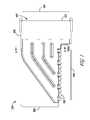
- FIG. 1is a side view of an example right-angle connector assembly.
- the connector housing 102may contain a plurality of leadframe assemblies 300 A-D.
- Each leadframe assembly 300 A-Dmay include a respective dielectric housing 404 A-D.
- Each dielectric housing 404 A-Dmay retain one or more ground plates 406 A-D, which may be made from a metal, metalized plastic, or magnetic absorbing material.
- Each leadframe assembly 300 A-Dmay also be devoid of shields.
- a dielectric housing 404 A-Dmay be insert molded over a respective leadframe 202 (shown in FIG. 2 ) of electrical contacts 101 A-H.
- the air pocket 502can be moved so that the shorter electrical contact, such as electrical contact 101 F ( FIG. 2 ), is physically closer to a first end of the air pocket 502 (i.e., a distance XS away from the plastic) and the longer electrical contact 101 E ( FIG. 2 ) is farther away from the opposite end of the air pocket (i.e., a distance XL away from the plastic).
- the effective dielectric constant for the shorter electrical contact 101 FFIG. 2
- the effective dielectric constant for the shorter electrical contact 101 Fmay be increased, which increases the time delay for a signal carried through that electrical contact.
- in-pair skewmay be controlled.
- a second manufactured connector 100may be manufactured from the design.
- the leadframe housing 404 D of the second manufactured connectormay define an air pocket 502 of a second size adjacent to the pair 210 of electrical contacts 101 E, 101 F.
- the size of the first air pocket 502may be different from the size of the second air pocket 502 .
- the second manufactured connector 100may have a second connector impedance Z 2 that is different from the first connector impedance Z 1 .
Landscapes
- Details Of Connecting Devices For Male And Female Coupling (AREA)
- Coupling Device And Connection With Printed Circuit (AREA)
Abstract
Description
Claims (21)
Priority Applications (4)
| Application Number | Priority Date | Filing Date | Title |
|---|---|---|---|
| US12/828,824US8231415B2 (en) | 2009-07-10 | 2010-07-01 | High speed backplane connector with impedance modification and skew correction |
| PCT/US2010/040899WO2011005682A2 (en) | 2009-07-10 | 2010-07-02 | High speed backplane connector with impedance modification and skew connection |
| CN201080035500.9ACN102474050B (en) | 2009-07-10 | 2010-07-02 | High speed backplane connector with impedance modification and offset correction |
| TW099122749ATWI412184B (en) | 2009-07-10 | 2010-07-09 | High speed backplane connector with impedance correction and skew correction |
Applications Claiming Priority (2)
| Application Number | Priority Date | Filing Date | Title |
|---|---|---|---|
| US22473309P | 2009-07-10 | 2009-07-10 | |
| US12/828,824US8231415B2 (en) | 2009-07-10 | 2010-07-01 | High speed backplane connector with impedance modification and skew correction |
Publications (2)
| Publication Number | Publication Date |
|---|---|
| US20110009011A1 US20110009011A1 (en) | 2011-01-13 |
| US8231415B2true US8231415B2 (en) | 2012-07-31 |
Family
ID=43427826
Family Applications (1)
| Application Number | Title | Priority Date | Filing Date |
|---|---|---|---|
| US12/828,824Active2030-07-12US8231415B2 (en) | 2009-07-10 | 2010-07-01 | High speed backplane connector with impedance modification and skew correction |
Country Status (4)
| Country | Link |
|---|---|
| US (1) | US8231415B2 (en) |
| CN (1) | CN102474050B (en) |
| TW (1) | TWI412184B (en) |
| WO (1) | WO2011005682A2 (en) |
Cited By (21)
| Publication number | Priority date | Publication date | Assignee | Title |
|---|---|---|---|---|
| US20110159744A1 (en)* | 2009-12-30 | 2011-06-30 | Buck Jonathan E | Electrical connector having impedance tuning ribs |
| US20110195607A1 (en)* | 2008-09-30 | 2011-08-11 | Jeroen De Bruijn | Lead frame assembly for an electrical connector |
| US20120178292A1 (en)* | 2011-01-06 | 2012-07-12 | Fujitsu Component Limited | Connector |
| US20140073173A1 (en)* | 2012-09-07 | 2014-03-13 | All Best Electronics Co., Ltd. | Electrical connector |
| USD718253S1 (en) | 2012-04-13 | 2014-11-25 | Fci Americas Technology Llc | Electrical cable connector |
| US8905651B2 (en) | 2012-01-31 | 2014-12-09 | Fci | Dismountable optical coupling device |
| USD720698S1 (en) | 2013-03-15 | 2015-01-06 | Fci Americas Technology Llc | Electrical cable connector |
| US20150024635A1 (en)* | 2013-07-16 | 2015-01-22 | Tyco Electronics Corporation | Electrical connector for transmitting data signals |
| US8944831B2 (en) | 2012-04-13 | 2015-02-03 | Fci Americas Technology Llc | Electrical connector having ribbed ground plate with engagement members |
| US20150079821A1 (en)* | 2013-09-17 | 2015-03-19 | Topconn Electronic (Kunshan) Co., Ltd | Communication connector and terminal lead frame thereof |
| USD727268S1 (en) | 2012-04-13 | 2015-04-21 | Fci Americas Technology Llc | Vertical electrical connector |
| USD727852S1 (en) | 2012-04-13 | 2015-04-28 | Fci Americas Technology Llc | Ground shield for a right angle electrical connector |
| US9048583B2 (en) | 2009-03-19 | 2015-06-02 | Fci Americas Technology Llc | Electrical connector having ribbed ground plate |
| USD733662S1 (en) | 2013-01-25 | 2015-07-07 | Fci Americas Technology Llc | Connector housing for electrical connector |
| US9136634B2 (en) | 2010-09-03 | 2015-09-15 | Fci Americas Technology Llc | Low-cross-talk electrical connector |
| USD746236S1 (en) | 2012-07-11 | 2015-12-29 | Fci Americas Technology Llc | Electrical connector housing |
| US9231393B2 (en) | 2012-04-13 | 2016-01-05 | Fci Americas Technology Llc | Electrical assembly with organizer |
| US9257778B2 (en) | 2012-04-13 | 2016-02-09 | Fci Americas Technology | High speed electrical connector |
| US9300103B2 (en) | 2011-04-04 | 2016-03-29 | Fci Americas Technology Llc | Electrical connector |
| US9543703B2 (en) | 2012-07-11 | 2017-01-10 | Fci Americas Technology Llc | Electrical connector with reduced stack height |
| US9545040B2 (en) | 2012-01-23 | 2017-01-10 | Fci Americas Technology Llc | Cable retention housing |
Families Citing this family (10)
| Publication number | Priority date | Publication date | Assignee | Title |
|---|---|---|---|---|
| US8313354B2 (en)* | 2010-06-01 | 2012-11-20 | Tyco Electronics Corporation | Socket contact for a header connector |
| US9281624B2 (en)* | 2013-08-16 | 2016-03-08 | Tyco Electronics Corporation | Electrical connector with signal pathways and a system having the same |
| US10498086B2 (en)* | 2016-01-12 | 2019-12-03 | Fci Usa Llc | Differential pair signal contacts with skew correction |
| CN110800172B (en) | 2017-04-28 | 2021-06-04 | 富加宜(美国)有限责任公司 | High frequency BGA connector |
| TWI828624B (en) | 2017-06-13 | 2024-01-11 | 美商山姆科技公司 | Electrical connector system and method using the same |
| USD964291S1 (en) | 2017-07-21 | 2022-09-20 | Samtec, Inc. | Electrical connector |
| US11289850B2 (en) | 2017-07-21 | 2022-03-29 | Samtec, Inc. | Electrical connector having latch |
| CN110277699B (en)* | 2019-05-28 | 2021-03-16 | 番禺得意精密电子工业有限公司 | Electrical connector |
| WO2021154702A1 (en) | 2020-01-27 | 2021-08-05 | Fci Usa Llc | High speed connector |
| TWI887339B (en)* | 2020-01-27 | 2025-06-21 | 美商Fci美國有限責任公司 | High speed, high density direct mate orthogonal connector |
Citations (94)
| Publication number | Priority date | Publication date | Assignee | Title |
|---|---|---|---|---|
| US4464003A (en) | 1982-11-01 | 1984-08-07 | Amp Incorporated | Insulation displacing connector with programmable ground bussing feature |
| DE3529218A1 (en) | 1984-08-17 | 1986-02-27 | Teradyne Inc., Boston, Mass. | CONNECTING DEVICE FOR CIRCUIT BOARDS |
| US4596428A (en) | 1984-03-12 | 1986-06-24 | Minnesota Mining And Manufacturing Company | Multi-conductor cable/contact connection assembly and method |
| US4632476A (en) | 1985-08-30 | 1986-12-30 | At&T Bell Laboratories | Terminal grounding unit |
| EP0212764A2 (en) | 1985-08-05 | 1987-03-04 | Criton Technologies partn. comp. of Criton Corp. B.S.B. Diversified Co., Inc., Royal Zenith Corp, d/b/a Viking Connectors Co. | High density, controlled impedance connector |
| US4655515A (en) | 1985-07-12 | 1987-04-07 | Amp Incorporated | Double row electrical connector |
| DE3605316A1 (en) | 1986-02-19 | 1987-08-20 | Siemens Ag | Multipole plug connector |
| US4705332A (en) | 1985-08-05 | 1987-11-10 | Criton Technologies | High density, controlled impedance connectors |
| US4806107A (en) | 1987-10-16 | 1989-02-21 | American Telephone And Telegraph Company, At&T Bell Laboratories | High frequency connector |
| US4820169A (en) | 1986-04-22 | 1989-04-11 | Amp Incorporated | Programmable modular connector assembly |
| US4824383A (en) | 1986-11-18 | 1989-04-25 | E. I. Du Pont De Nemours And Company | Terminator and corresponding receptacle for multiple electrical conductors |
| US4836791A (en) | 1987-11-16 | 1989-06-06 | Amp Incorporated | High density coax connector |
| US4846727A (en) | 1988-04-11 | 1989-07-11 | Amp Incorporated | Reference conductor for improving signal integrity in electrical connectors |
| US4854899A (en) | 1987-11-24 | 1989-08-08 | Elcon Products International Company | Terminal bus junction with multiple, displaced contact points |
| US4882554A (en) | 1987-05-29 | 1989-11-21 | Sony Corp. | Multi-drop type bus line system |
| US4952172A (en) | 1989-07-14 | 1990-08-28 | Amp Incorporated | Electrical connector stiffener device |
| US4975069A (en) | 1989-11-01 | 1990-12-04 | Amp Incorporated | Electrical modular connector |
| US4975084A (en) | 1988-10-17 | 1990-12-04 | Amp Incorporated | Electrical connector system |
| DE4040551A1 (en) | 1989-12-20 | 1991-06-27 | Amp Inc | ELECTRICAL CONNECTOR ARRANGEMENT |
| EP0442785A1 (en) | 1990-02-13 | 1991-08-21 | Elf Atochem S.A. | Process for purification of polyorganophosphazene solutions or suspensions by means of membranes |
| US5046960A (en) | 1990-12-20 | 1991-09-10 | Amp Incorporated | High density connector system |
| US5066236A (en) | 1989-10-10 | 1991-11-19 | Amp Incorporated | Impedance matched backplane connector |
| US5083238A (en) | 1991-02-04 | 1992-01-21 | Motorola, Inc. | High frequency electronic assembly |
| EP0486298A1 (en) | 1990-11-15 | 1992-05-20 | The Whitaker Corporation | Multicontact connector for signal transmission |
| US5117331A (en) | 1991-05-16 | 1992-05-26 | Compaq Computer Corporation | Bus control signal routing and termination |
| US5224867A (en) | 1990-10-08 | 1993-07-06 | Daiichi Denshi Kogyo Kabushiki Kaisha | Electrical connector for coaxial flat cable |
| US5228864A (en) | 1990-06-08 | 1993-07-20 | E. I. Du Pont De Nemours And Company | Connectors with ground structure |
| US5342211A (en) | 1992-03-09 | 1994-08-30 | The Whitaker Corporation | Shielded back plane connector |
| US5354219A (en) | 1990-12-21 | 1994-10-11 | Vemako Ab | Multipolar screened connector having a common earth |
| US5403206A (en) | 1993-04-05 | 1995-04-04 | Teradyne, Inc. | Shielded electrical connector |
| US5429520A (en) | 1993-06-04 | 1995-07-04 | Framatome Connectors International | Connector assembly |
| US5496183A (en) | 1993-04-06 | 1996-03-05 | The Whitaker Corporation | Prestressed shielding plates for electrical connectors |
| US5580283A (en) | 1995-09-08 | 1996-12-03 | Molex Incorporated | Electrical connector having terminal modules |
| EP0562691B1 (en) | 1992-03-26 | 1997-06-04 | Berg Electronics Manufacturing B.V. | Connector |
| US5718606A (en) | 1996-10-30 | 1998-02-17 | Component Equipment Company, Inc. | Electrical connector between a pair of printed circuit boards |
| US5743765A (en) | 1994-07-22 | 1998-04-28 | Berg Technology, Inc. | Selectively metallized connector with at least one coaxial or twin-axial terminal |
| US5795191A (en) | 1996-09-11 | 1998-08-18 | Preputnick; George | Connector assembly with shielded modules and method of making same |
| US5851121A (en) | 1996-04-01 | 1998-12-22 | Framatome Connectors International | Miniature shielded connector with elbow contact shafts |
| US5913702A (en) | 1994-08-08 | 1999-06-22 | Framatome Connectors International | Low cross-talk network connector |
| US5938479A (en) | 1997-04-02 | 1999-08-17 | Communications Systems, Inc. | Connector for reducing electromagnetic field coupling |
| US6027381A (en) | 1998-12-28 | 2000-02-22 | Hon Hai Precision Ind. Co., Ltd. | Insert molded compression connector |
| US6042394A (en) | 1995-04-19 | 2000-03-28 | Berg Technology, Inc. | Right-angle connector |
| US6050842A (en) | 1996-09-27 | 2000-04-18 | The Whitaker Corporation | Electrical connector with paired terminals |
| US6083047A (en) | 1997-01-16 | 2000-07-04 | Berg Technology, Inc. | Modular electrical PCB assembly connector |
| US6113418A (en) | 1993-03-12 | 2000-09-05 | Cekan/Cdt A/S | Connector element for telecommunication |
| US6206735B1 (en) | 1998-08-28 | 2001-03-27 | Teka Interconnection Systems, Inc. | Press fit print circuit board connector |
| US6244887B1 (en) | 1999-03-19 | 2001-06-12 | Molex Incorporated | Electrical connector assembly |
| EP1111730A2 (en) | 1999-12-23 | 2001-06-27 | Molex Incorporated | Electrical connector assembly with screen and ESD protection |
| US6290552B1 (en) | 1999-05-18 | 2001-09-18 | Yazaki Corporation | Battery connection plate and a manufacturing method therefor |
| US20010041477A1 (en) | 2000-03-29 | 2001-11-15 | Billman Timothy B. | Electrical connector with grounding system |
| US20020013101A1 (en) | 2000-03-31 | 2002-01-31 | Long Michael D. | Connector assembly with stabilized modules |
| US6347962B1 (en) | 2001-01-30 | 2002-02-19 | Tyco Electronics Corporation | Connector assembly with multi-contact ground shields |
| US6361376B1 (en) | 1997-12-25 | 2002-03-26 | Yazaki Corporation | Connector, method of manufacturing the same and die structure for executing the method |
| US6371813B2 (en) | 1998-08-12 | 2002-04-16 | Robinson Nugent, Inc. | Connector apparatus |
| US6375508B1 (en) | 2000-12-26 | 2002-04-23 | Hon Hai Precision Ind. Co.., Ltd. | Electrical connector assembly having the same circuit boards therein |
| US6379188B1 (en) | 1997-02-07 | 2002-04-30 | Teradyne, Inc. | Differential signal electrical connectors |
| US20020106932A1 (en) | 2001-02-06 | 2002-08-08 | HOLLAND Simon | Low profile electrical connector |
| US20020142629A1 (en) | 2001-03-27 | 2002-10-03 | Victor Zaderej | Board mounted electrical connector assembly |
| US20020173177A1 (en) | 2001-05-15 | 2002-11-21 | Korsunsky Iosif R. | High-speed card edge connector |
| US6491545B1 (en) | 2000-05-05 | 2002-12-10 | Molex Incorporated | Modular shielded coaxial cable connector |
| US6503103B1 (en) | 1997-02-07 | 2003-01-07 | Teradyne, Inc. | Differential signal electrical connectors |
| US6517360B1 (en) | 2000-02-03 | 2003-02-11 | Teradyne, Inc. | High speed pressure mount connector |
| US6527588B2 (en) | 1997-01-16 | 2003-03-04 | Fci Americas Technology, Inc. | Electrical connector with integrated PCB assembly |
| US6544072B2 (en) | 2001-06-12 | 2003-04-08 | Berg Technologies | Electrical connector with metallized polymeric housing |
| US6551140B2 (en) | 2001-05-09 | 2003-04-22 | Hon Hai Precision Ind. Co., Ltd. | Electrical connector having differential pair terminals with equal length |
| US6602095B2 (en) | 2001-01-25 | 2003-08-05 | Teradyne, Inc. | Shielded waferized connector |
| US6623310B1 (en) | 2002-05-21 | 2003-09-23 | Hon Hai Precision Ind. Co., Ltd. | High density electrical connector assembly with reduced insertion force |
| US6652318B1 (en) | 2002-05-24 | 2003-11-25 | Fci Americas Technology, Inc. | Cross-talk canceling technique for high speed electrical connectors |
| US6666693B2 (en) | 2001-11-20 | 2003-12-23 | Fci Americas Technology, Inc. | Surface-mounted right-angle electrical connector |
| US20040018757A1 (en) | 2002-05-06 | 2004-01-29 | Lang Harold Keith | Board-to-board connector with compliant mounting pins |
| US6692272B2 (en) | 2001-11-14 | 2004-02-17 | Fci Americas Technology, Inc. | High speed electrical connector |
| US6702590B2 (en) | 2001-06-13 | 2004-03-09 | Molex Incorporated | High-speed mezzanine connector with conductive housing |
| US6709294B1 (en) | 2002-12-17 | 2004-03-23 | Teradyne, Inc. | Electrical connector with conductive plastic features |
| US6712646B2 (en) | 2000-10-20 | 2004-03-30 | Japan Aviation Electronics Industry, Limited | High-speed transmission connector with a ground structure having an improved shielding function |
| US6739910B1 (en) | 2003-07-11 | 2004-05-25 | Hon Hai Precision Ind. Co., Ltd. | Cable assembly with internal circuit modules |
| US6746278B2 (en) | 2001-11-28 | 2004-06-08 | Molex Incorporated | Interstitial ground assembly for connector |
| US6814619B1 (en) | 2003-06-26 | 2004-11-09 | Teradyne, Inc. | High speed, high density electrical connector and connector assembly |
| US20050026503A1 (en) | 2003-07-31 | 2005-02-03 | Trout David A. | Metal contact LGA socket |
| US6872085B1 (en) | 2003-09-30 | 2005-03-29 | Teradyne, Inc. | High speed, high density electrical connector assembly |
| US6979202B2 (en) | 2001-01-12 | 2005-12-27 | Litton Systems, Inc. | High-speed electrical connector |
| US7040901B2 (en) | 2001-01-12 | 2006-05-09 | Litton Systems, Inc. | High-speed electrical connector |
| US7163421B1 (en)* | 2005-06-30 | 2007-01-16 | Amphenol Corporation | High speed high density electrical connector |
| US20070021002A1 (en) | 2005-03-31 | 2007-01-25 | Molex Incorporated | High-density, robust connector |
| US20070099512A1 (en) | 2005-11-02 | 2007-05-03 | Japan Aviation Electronics Industry, Limited | Connector in which a mutual distance between contacts is adjusted at terminal portions thereof |
| US7316585B2 (en) | 2006-05-30 | 2008-01-08 | Fci Americas Technology, Inc. | Reducing suck-out insertion loss |
| US7347740B2 (en) | 2005-11-21 | 2008-03-25 | Fci Americas Technology, Inc. | Mechanically robust lead frame assembly for an electrical connector |
| US7384311B2 (en) | 2006-02-27 | 2008-06-10 | Tyco Electronics Corporation | Electrical connector having contact modules with terminal exposing slots |
| US7422483B2 (en) | 2005-02-22 | 2008-09-09 | Molex Incorproated | Differential signal connector with wafer-style construction |
| US20080246555A1 (en) | 2007-04-04 | 2008-10-09 | Brian Kirk | Differential electrical connector with skew control |
| US20080316729A1 (en) | 2007-06-25 | 2008-12-25 | Tyco Electronics Corporation | Skew controlled leadframe for a contact module assembly |
| US20090011643A1 (en)* | 2007-06-20 | 2009-01-08 | Molex Incorporated | Impedance control in connector mounting areas |
| US7497736B2 (en) | 2006-12-19 | 2009-03-03 | Fci Americas Technology, Inc. | Shieldless, high-speed, low-cross-talk electrical connector |
| US7588463B2 (en) | 2007-04-26 | 2009-09-15 | Kyocera Elco Corporation | Connector and method of producing the same |
| US20100240233A1 (en) | 2009-03-19 | 2010-09-23 | Johnescu Douglas M | Electrical connector having ribbed ground plate |
- 2010
- 2010-07-01USUS12/828,824patent/US8231415B2/enactiveActive
- 2010-07-02CNCN201080035500.9Apatent/CN102474050B/enactiveActive
- 2010-07-02WOPCT/US2010/040899patent/WO2011005682A2/enactiveApplication Filing
- 2010-07-09TWTW099122749Apatent/TWI412184B/enactive
Patent Citations (108)
| Publication number | Priority date | Publication date | Assignee | Title |
|---|---|---|---|---|
| US4464003A (en) | 1982-11-01 | 1984-08-07 | Amp Incorporated | Insulation displacing connector with programmable ground bussing feature |
| US4596428A (en) | 1984-03-12 | 1986-06-24 | Minnesota Mining And Manufacturing Company | Multi-conductor cable/contact connection assembly and method |
| DE3529218A1 (en) | 1984-08-17 | 1986-02-27 | Teradyne Inc., Boston, Mass. | CONNECTING DEVICE FOR CIRCUIT BOARDS |
| US4655515A (en) | 1985-07-12 | 1987-04-07 | Amp Incorporated | Double row electrical connector |
| EP0212764A2 (en) | 1985-08-05 | 1987-03-04 | Criton Technologies partn. comp. of Criton Corp. B.S.B. Diversified Co., Inc., Royal Zenith Corp, d/b/a Viking Connectors Co. | High density, controlled impedance connector |
| US4705332A (en) | 1985-08-05 | 1987-11-10 | Criton Technologies | High density, controlled impedance connectors |
| US4632476A (en) | 1985-08-30 | 1986-12-30 | At&T Bell Laboratories | Terminal grounding unit |
| DE3605316A1 (en) | 1986-02-19 | 1987-08-20 | Siemens Ag | Multipole plug connector |
| US4820169A (en) | 1986-04-22 | 1989-04-11 | Amp Incorporated | Programmable modular connector assembly |
| US4824383A (en) | 1986-11-18 | 1989-04-25 | E. I. Du Pont De Nemours And Company | Terminator and corresponding receptacle for multiple electrical conductors |
| US4882554A (en) | 1987-05-29 | 1989-11-21 | Sony Corp. | Multi-drop type bus line system |
| US4806107A (en) | 1987-10-16 | 1989-02-21 | American Telephone And Telegraph Company, At&T Bell Laboratories | High frequency connector |
| US4836791A (en) | 1987-11-16 | 1989-06-06 | Amp Incorporated | High density coax connector |
| US4854899A (en) | 1987-11-24 | 1989-08-08 | Elcon Products International Company | Terminal bus junction with multiple, displaced contact points |
| US4846727A (en) | 1988-04-11 | 1989-07-11 | Amp Incorporated | Reference conductor for improving signal integrity in electrical connectors |
| US4975084A (en) | 1988-10-17 | 1990-12-04 | Amp Incorporated | Electrical connector system |
| US4952172A (en) | 1989-07-14 | 1990-08-28 | Amp Incorporated | Electrical connector stiffener device |
| US5066236A (en) | 1989-10-10 | 1991-11-19 | Amp Incorporated | Impedance matched backplane connector |
| US4975069A (en) | 1989-11-01 | 1990-12-04 | Amp Incorporated | Electrical modular connector |
| DE4040551A1 (en) | 1989-12-20 | 1991-06-27 | Amp Inc | ELECTRICAL CONNECTOR ARRANGEMENT |
| US5104341A (en) | 1989-12-20 | 1992-04-14 | Amp Incorporated | Shielded backplane connector |
| EP0442785A1 (en) | 1990-02-13 | 1991-08-21 | Elf Atochem S.A. | Process for purification of polyorganophosphazene solutions or suspensions by means of membranes |
| US5228864A (en) | 1990-06-08 | 1993-07-20 | E. I. Du Pont De Nemours And Company | Connectors with ground structure |
| US5224867A (en) | 1990-10-08 | 1993-07-06 | Daiichi Denshi Kogyo Kabushiki Kaisha | Electrical connector for coaxial flat cable |
| EP0486298A1 (en) | 1990-11-15 | 1992-05-20 | The Whitaker Corporation | Multicontact connector for signal transmission |
| EP0486298B1 (en) | 1990-11-15 | 1996-01-31 | The Whitaker Corporation | Multicontact connector for signal transmission |
| US5046960A (en) | 1990-12-20 | 1991-09-10 | Amp Incorporated | High density connector system |
| US5354219A (en) | 1990-12-21 | 1994-10-11 | Vemako Ab | Multipolar screened connector having a common earth |
| US5083238A (en) | 1991-02-04 | 1992-01-21 | Motorola, Inc. | High frequency electronic assembly |
| US5117331A (en) | 1991-05-16 | 1992-05-26 | Compaq Computer Corporation | Bus control signal routing and termination |
| US5342211A (en) | 1992-03-09 | 1994-08-30 | The Whitaker Corporation | Shielded back plane connector |
| EP0560550B1 (en) | 1992-03-09 | 1997-07-16 | The Whitaker Corporation | Shielded back plane connector |
| EP0562691B1 (en) | 1992-03-26 | 1997-06-04 | Berg Electronics Manufacturing B.V. | Connector |
| US6113418A (en) | 1993-03-12 | 2000-09-05 | Cekan/Cdt A/S | Connector element for telecommunication |
| US5403206A (en) | 1993-04-05 | 1995-04-04 | Teradyne, Inc. | Shielded electrical connector |
| US5496183A (en) | 1993-04-06 | 1996-03-05 | The Whitaker Corporation | Prestressed shielding plates for electrical connectors |
| US5433617A (en) | 1993-06-04 | 1995-07-18 | Framatome Connectors International | Connector assembly for printed circuit boards |
| US5433618A (en) | 1993-06-04 | 1995-07-18 | Framatome Connectors International | Connector assembly |
| US5429520A (en) | 1993-06-04 | 1995-07-04 | Framatome Connectors International | Connector assembly |
| US5743765A (en) | 1994-07-22 | 1998-04-28 | Berg Technology, Inc. | Selectively metallized connector with at least one coaxial or twin-axial terminal |
| US5913702A (en) | 1994-08-08 | 1999-06-22 | Framatome Connectors International | Low cross-talk network connector |
| US6042394A (en) | 1995-04-19 | 2000-03-28 | Berg Technology, Inc. | Right-angle connector |
| US5580283A (en) | 1995-09-08 | 1996-12-03 | Molex Incorporated | Electrical connector having terminal modules |
| US5943770A (en) | 1996-04-01 | 1999-08-31 | Framatome Connectors International | Method of making miniature shielded connector with elbow contact shafts |
| US5851121A (en) | 1996-04-01 | 1998-12-22 | Framatome Connectors International | Miniature shielded connector with elbow contact shafts |
| US5795191A (en) | 1996-09-11 | 1998-08-18 | Preputnick; George | Connector assembly with shielded modules and method of making same |
| US6050842A (en) | 1996-09-27 | 2000-04-18 | The Whitaker Corporation | Electrical connector with paired terminals |
| US5718606A (en) | 1996-10-30 | 1998-02-17 | Component Equipment Company, Inc. | Electrical connector between a pair of printed circuit boards |
| US6527588B2 (en) | 1997-01-16 | 2003-03-04 | Fci Americas Technology, Inc. | Electrical connector with integrated PCB assembly |
| US6083047A (en) | 1997-01-16 | 2000-07-04 | Berg Technology, Inc. | Modular electrical PCB assembly connector |
| US6503103B1 (en) | 1997-02-07 | 2003-01-07 | Teradyne, Inc. | Differential signal electrical connectors |
| US6379188B1 (en) | 1997-02-07 | 2002-04-30 | Teradyne, Inc. | Differential signal electrical connectors |
| US6607402B2 (en) | 1997-02-07 | 2003-08-19 | Teradyne, Inc. | Printed circuit board for differential signal electrical connectors |
| US5938479A (en) | 1997-04-02 | 1999-08-17 | Communications Systems, Inc. | Connector for reducing electromagnetic field coupling |
| US6361376B1 (en) | 1997-12-25 | 2002-03-26 | Yazaki Corporation | Connector, method of manufacturing the same and die structure for executing the method |
| US6371813B2 (en) | 1998-08-12 | 2002-04-16 | Robinson Nugent, Inc. | Connector apparatus |
| US6206735B1 (en) | 1998-08-28 | 2001-03-27 | Teka Interconnection Systems, Inc. | Press fit print circuit board connector |
| US6027381A (en) | 1998-12-28 | 2000-02-22 | Hon Hai Precision Ind. Co., Ltd. | Insert molded compression connector |
| US6244887B1 (en) | 1999-03-19 | 2001-06-12 | Molex Incorporated | Electrical connector assembly |
| US6290552B1 (en) | 1999-05-18 | 2001-09-18 | Yazaki Corporation | Battery connection plate and a manufacturing method therefor |
| US20010046816A1 (en) | 1999-05-18 | 2001-11-29 | Satoshi Saito | Battery connection plate and a manufacturing method therefor |
| US6431921B2 (en) | 1999-05-18 | 2002-08-13 | Yazaki Corp. | Battery connection plate having busbar and terminal |
| EP1111730A2 (en) | 1999-12-23 | 2001-06-27 | Molex Incorporated | Electrical connector assembly with screen and ESD protection |
| US6517360B1 (en) | 2000-02-03 | 2003-02-11 | Teradyne, Inc. | High speed pressure mount connector |
| US20010041477A1 (en) | 2000-03-29 | 2001-11-15 | Billman Timothy B. | Electrical connector with grounding system |
| US20020013101A1 (en) | 2000-03-31 | 2002-01-31 | Long Michael D. | Connector assembly with stabilized modules |
| US6491545B1 (en) | 2000-05-05 | 2002-12-10 | Molex Incorporated | Modular shielded coaxial cable connector |
| US6712646B2 (en) | 2000-10-20 | 2004-03-30 | Japan Aviation Electronics Industry, Limited | High-speed transmission connector with a ground structure having an improved shielding function |
| US6375508B1 (en) | 2000-12-26 | 2002-04-23 | Hon Hai Precision Ind. Co.., Ltd. | Electrical connector assembly having the same circuit boards therein |
| US7040901B2 (en) | 2001-01-12 | 2006-05-09 | Litton Systems, Inc. | High-speed electrical connector |
| US6979202B2 (en) | 2001-01-12 | 2005-12-27 | Litton Systems, Inc. | High-speed electrical connector |
| US6602095B2 (en) | 2001-01-25 | 2003-08-05 | Teradyne, Inc. | Shielded waferized connector |
| US6347962B1 (en) | 2001-01-30 | 2002-02-19 | Tyco Electronics Corporation | Connector assembly with multi-contact ground shields |
| US20020106932A1 (en) | 2001-02-06 | 2002-08-08 | HOLLAND Simon | Low profile electrical connector |
| US20020142629A1 (en) | 2001-03-27 | 2002-10-03 | Victor Zaderej | Board mounted electrical connector assembly |
| US6551140B2 (en) | 2001-05-09 | 2003-04-22 | Hon Hai Precision Ind. Co., Ltd. | Electrical connector having differential pair terminals with equal length |
| US20020173177A1 (en) | 2001-05-15 | 2002-11-21 | Korsunsky Iosif R. | High-speed card edge connector |
| US6544072B2 (en) | 2001-06-12 | 2003-04-08 | Berg Technologies | Electrical connector with metallized polymeric housing |
| US6702590B2 (en) | 2001-06-13 | 2004-03-09 | Molex Incorporated | High-speed mezzanine connector with conductive housing |
| US6692272B2 (en) | 2001-11-14 | 2004-02-17 | Fci Americas Technology, Inc. | High speed electrical connector |
| US6666693B2 (en) | 2001-11-20 | 2003-12-23 | Fci Americas Technology, Inc. | Surface-mounted right-angle electrical connector |
| US6746278B2 (en) | 2001-11-28 | 2004-06-08 | Molex Incorporated | Interstitial ground assembly for connector |
| US20040087196A1 (en) | 2002-05-06 | 2004-05-06 | Lang Harold Keith | Differential signal connectors with ESD protection |
| US20040072470A1 (en) | 2002-05-06 | 2004-04-15 | Lang Harold Keith | Terminal assemblies for differential signal connector |
| US20040038590A1 (en) | 2002-05-06 | 2004-02-26 | Lang Harold Keith | High-speed differential signal connector with interstitial ground aspect |
| US20040018757A1 (en) | 2002-05-06 | 2004-01-29 | Lang Harold Keith | Board-to-board connector with compliant mounting pins |
| US6918789B2 (en) | 2002-05-06 | 2005-07-19 | Molex Incorporated | High-speed differential signal connector particularly suitable for docking applications |
| US6623310B1 (en) | 2002-05-21 | 2003-09-23 | Hon Hai Precision Ind. Co., Ltd. | High density electrical connector assembly with reduced insertion force |
| US6652318B1 (en) | 2002-05-24 | 2003-11-25 | Fci Americas Technology, Inc. | Cross-talk canceling technique for high speed electrical connectors |
| US6709294B1 (en) | 2002-12-17 | 2004-03-23 | Teradyne, Inc. | Electrical connector with conductive plastic features |
| US6814619B1 (en) | 2003-06-26 | 2004-11-09 | Teradyne, Inc. | High speed, high density electrical connector and connector assembly |
| US6739910B1 (en) | 2003-07-11 | 2004-05-25 | Hon Hai Precision Ind. Co., Ltd. | Cable assembly with internal circuit modules |
| US20050026503A1 (en) | 2003-07-31 | 2005-02-03 | Trout David A. | Metal contact LGA socket |
| US6872085B1 (en) | 2003-09-30 | 2005-03-29 | Teradyne, Inc. | High speed, high density electrical connector assembly |
| US7422483B2 (en) | 2005-02-22 | 2008-09-09 | Molex Incorproated | Differential signal connector with wafer-style construction |
| US20070021002A1 (en) | 2005-03-31 | 2007-01-25 | Molex Incorporated | High-density, robust connector |
| US7163421B1 (en)* | 2005-06-30 | 2007-01-16 | Amphenol Corporation | High speed high density electrical connector |
| US20070099512A1 (en) | 2005-11-02 | 2007-05-03 | Japan Aviation Electronics Industry, Limited | Connector in which a mutual distance between contacts is adjusted at terminal portions thereof |
| JP2007128706A (en) | 2005-11-02 | 2007-05-24 | Japan Aviation Electronics Industry Ltd | Connector |
| US7347740B2 (en) | 2005-11-21 | 2008-03-25 | Fci Americas Technology, Inc. | Mechanically robust lead frame assembly for an electrical connector |
| US7384311B2 (en) | 2006-02-27 | 2008-06-10 | Tyco Electronics Corporation | Electrical connector having contact modules with terminal exposing slots |
| US7316585B2 (en) | 2006-05-30 | 2008-01-08 | Fci Americas Technology, Inc. | Reducing suck-out insertion loss |
| US7497736B2 (en) | 2006-12-19 | 2009-03-03 | Fci Americas Technology, Inc. | Shieldless, high-speed, low-cross-talk electrical connector |
| US20080246555A1 (en) | 2007-04-04 | 2008-10-09 | Brian Kirk | Differential electrical connector with skew control |
| US7588463B2 (en) | 2007-04-26 | 2009-09-15 | Kyocera Elco Corporation | Connector and method of producing the same |
| US20090011643A1 (en)* | 2007-06-20 | 2009-01-08 | Molex Incorporated | Impedance control in connector mounting areas |
| US20080316729A1 (en) | 2007-06-25 | 2008-12-25 | Tyco Electronics Corporation | Skew controlled leadframe for a contact module assembly |
| US20100240233A1 (en) | 2009-03-19 | 2010-09-23 | Johnescu Douglas M | Electrical connector having ribbed ground plate |
Non-Patent Citations (5)
| Title |
|---|
| Derman "Speed, Density Push Design Xomplexities," Electronic Engineering Times, May 1998. |
| IBM Bulletin, Shielded In-Line Electrical Multiconnector, Aug. 1967, 10(3). |
| International Application No. PCT/US2003/014370, International Search Report dated Aug. 6, 2003, 2 pages. |
| International Application No. PCT/US2010/040899, International Search Report dated Jan. 25, 2011, 9 pages. |
| Siemens, "SpeedPac: A New Concept for the Next Generation of Transmission Speed," Backplane Interconnection, Issue Jan. 1996. |
Cited By (40)
| Publication number | Priority date | Publication date | Assignee | Title |
|---|---|---|---|---|
| US8771023B2 (en)* | 2008-09-30 | 2014-07-08 | Fci | Lead frame assembly for an electrical connector |
| US20110195607A1 (en)* | 2008-09-30 | 2011-08-11 | Jeroen De Bruijn | Lead frame assembly for an electrical connector |
| US10096921B2 (en) | 2009-03-19 | 2018-10-09 | Fci Usa Llc | Electrical connector having ribbed ground plate |
| US10720721B2 (en) | 2009-03-19 | 2020-07-21 | Fci Usa Llc | Electrical connector having ribbed ground plate |
| US9048583B2 (en) | 2009-03-19 | 2015-06-02 | Fci Americas Technology Llc | Electrical connector having ribbed ground plate |
| US9461410B2 (en) | 2009-03-19 | 2016-10-04 | Fci Americas Technology Llc | Electrical connector having ribbed ground plate |
| US8715003B2 (en)* | 2009-12-30 | 2014-05-06 | Fci Americas Technology Llc | Electrical connector having impedance tuning ribs |
| US20110159744A1 (en)* | 2009-12-30 | 2011-06-30 | Buck Jonathan E | Electrical connector having impedance tuning ribs |
| US9136634B2 (en) | 2010-09-03 | 2015-09-15 | Fci Americas Technology Llc | Low-cross-talk electrical connector |
| US20120178292A1 (en)* | 2011-01-06 | 2012-07-12 | Fujitsu Component Limited | Connector |
| US9252541B2 (en)* | 2011-01-06 | 2016-02-02 | Fujitsu Component Limited | Connector |
| US9300103B2 (en) | 2011-04-04 | 2016-03-29 | Fci Americas Technology Llc | Electrical connector |
| US9545040B2 (en) | 2012-01-23 | 2017-01-10 | Fci Americas Technology Llc | Cable retention housing |
| US8905651B2 (en) | 2012-01-31 | 2014-12-09 | Fci | Dismountable optical coupling device |
| US8944831B2 (en) | 2012-04-13 | 2015-02-03 | Fci Americas Technology Llc | Electrical connector having ribbed ground plate with engagement members |
| USD750025S1 (en) | 2012-04-13 | 2016-02-23 | Fci Americas Technology Llc | Vertical electrical connector |
| USD718253S1 (en) | 2012-04-13 | 2014-11-25 | Fci Americas Technology Llc | Electrical cable connector |
| USD816044S1 (en) | 2012-04-13 | 2018-04-24 | Fci Americas Technology Llc | Electrical cable connector |
| USD727268S1 (en) | 2012-04-13 | 2015-04-21 | Fci Americas Technology Llc | Vertical electrical connector |
| US9831605B2 (en)* | 2012-04-13 | 2017-11-28 | Fci Americas Technology Llc | High speed electrical connector |
| USD790471S1 (en) | 2012-04-13 | 2017-06-27 | Fci Americas Technology Llc | Vertical electrical connector |
| US9231393B2 (en) | 2012-04-13 | 2016-01-05 | Fci Americas Technology Llc | Electrical assembly with organizer |
| USD748063S1 (en) | 2012-04-13 | 2016-01-26 | Fci Americas Technology Llc | Electrical ground shield |
| USD727852S1 (en) | 2012-04-13 | 2015-04-28 | Fci Americas Technology Llc | Ground shield for a right angle electrical connector |
| US9257778B2 (en) | 2012-04-13 | 2016-02-09 | Fci Americas Technology | High speed electrical connector |
| USD750030S1 (en) | 2012-04-13 | 2016-02-23 | Fci Americas Technology Llc | Electrical cable connector |
| USD751507S1 (en) | 2012-07-11 | 2016-03-15 | Fci Americas Technology Llc | Electrical connector |
| US9543703B2 (en) | 2012-07-11 | 2017-01-10 | Fci Americas Technology Llc | Electrical connector with reduced stack height |
| US9871323B2 (en) | 2012-07-11 | 2018-01-16 | Fci Americas Technology Llc | Electrical connector with reduced stack height |
| USD746236S1 (en) | 2012-07-11 | 2015-12-29 | Fci Americas Technology Llc | Electrical connector housing |
| US20140073173A1 (en)* | 2012-09-07 | 2014-03-13 | All Best Electronics Co., Ltd. | Electrical connector |
| USD745852S1 (en) | 2013-01-25 | 2015-12-22 | Fci Americas Technology Llc | Electrical connector |
| USD766832S1 (en) | 2013-01-25 | 2016-09-20 | Fci Americas Technology Llc | Electrical connector |
| USD733662S1 (en) | 2013-01-25 | 2015-07-07 | Fci Americas Technology Llc | Connector housing for electrical connector |
| USD772168S1 (en) | 2013-01-25 | 2016-11-22 | Fci Americas Technology Llc | Connector housing for electrical connector |
| USD720698S1 (en) | 2013-03-15 | 2015-01-06 | Fci Americas Technology Llc | Electrical cable connector |
| US8992253B2 (en)* | 2013-07-16 | 2015-03-31 | Tyco Electronics Corporation | Electrical connector for transmitting data signals |
| US20150024635A1 (en)* | 2013-07-16 | 2015-01-22 | Tyco Electronics Corporation | Electrical connector for transmitting data signals |
| US9130314B2 (en)* | 2013-09-17 | 2015-09-08 | Topconn Electronic (Kunshan) Co., Ltd. | Communication connector and terminal lead frame thereof |
| US20150079821A1 (en)* | 2013-09-17 | 2015-03-19 | Topconn Electronic (Kunshan) Co., Ltd | Communication connector and terminal lead frame thereof |
Also Published As
| Publication number | Publication date |
|---|---|
| TW201112517A (en) | 2011-04-01 |
| CN102474050A (en) | 2012-05-23 |
| US20110009011A1 (en) | 2011-01-13 |
| CN102474050B (en) | 2016-01-20 |
| TWI412184B (en) | 2013-10-11 |
| WO2011005682A3 (en) | 2011-04-07 |
| WO2011005682A2 (en) | 2011-01-13 |
Similar Documents
| Publication | Publication Date | Title |
|---|---|---|
| US8231415B2 (en) | High speed backplane connector with impedance modification and skew correction | |
| US10720721B2 (en) | Electrical connector having ribbed ground plate | |
| US11139620B2 (en) | Overmolded lead frame providing contact support and impedance matching properties | |
| US7462924B2 (en) | Electrical connector with elongated ground contacts | |
| US8480413B2 (en) | Electrical connector having commoned ground shields | |
| US8944831B2 (en) | Electrical connector having ribbed ground plate with engagement members | |
| US7708569B2 (en) | Broadside-coupled signal pair configurations for electrical connectors | |
| KR101076122B1 (en) | Impedance control in electrical connectors | |
| US8888529B2 (en) | Electrical connector having common ground shield | |
| US7524209B2 (en) | Impedance mating interface for electrical connectors | |
| US8267721B2 (en) | Electrical connector having ground plates and ground coupling bar | |
| US20040097112A1 (en) | Electrical connectors having contacts that may be selectively designated as either signal or ground contacts | |
| CN102684009B (en) | Electrical connectors with common ground shield | |
| EP2084785B1 (en) | Broadside-coupled signal pair configurations for electrical connectors | |
| US20230155328A1 (en) | High-speed electrical connector |
Legal Events
| Date | Code | Title | Description |
|---|---|---|---|
| AS | Assignment | Owner name:FCI AMERICAS TECHNOLOGY LLC, NEVADA Free format text:ASSIGNMENT OF ASSIGNORS INTEREST;ASSIGNORS:JOHNESCU, DOUGLAS M.;BUCK, JONATHAN E.;SMITH, STEPHEN B.;AND OTHERS;SIGNING DATES FROM 20100706 TO 20100707;REEL/FRAME:024695/0416 | |
| AS | Assignment | Owner name:FCI AMERICAS TECHNOLOGY LLC, NEVADA Free format text:CONVERSION TO LLC;ASSIGNOR:FCI AMERICAS TECHNOLOGY, INC.;REEL/FRAME:025957/0432 Effective date:20090930 | |
| FEPP | Fee payment procedure | Free format text:PAYOR NUMBER ASSIGNED (ORIGINAL EVENT CODE: ASPN); ENTITY STATUS OF PATENT OWNER: LARGE ENTITY | |
| STCF | Information on status: patent grant | Free format text:PATENTED CASE | |
| AS | Assignment | Owner name:WILMINGTON TRUST (LONDON) LIMITED, UNITED KINGDOM Free format text:SECURITY AGREEMENT;ASSIGNOR:FCI AMERICAS TECHNOLOGY LLC;REEL/FRAME:031896/0696 Effective date:20131227 | |
| FPAY | Fee payment | Year of fee payment:4 | |
| AS | Assignment | Owner name:FCI AMERICAS TECHNOLOGY LLC, NEVADA Free format text:RELEASE BY SECURED PARTY;ASSIGNOR:WILMINGTON TRUST (LONDON) LIMITED;REEL/FRAME:037484/0169 Effective date:20160108 | |
| MAFP | Maintenance fee payment | Free format text:PAYMENT OF MAINTENANCE FEE, 8TH YEAR, LARGE ENTITY (ORIGINAL EVENT CODE: M1552); ENTITY STATUS OF PATENT OWNER: LARGE ENTITY Year of fee payment:8 | |
| MAFP | Maintenance fee payment | Free format text:PAYMENT OF MAINTENANCE FEE, 12TH YEAR, LARGE ENTITY (ORIGINAL EVENT CODE: M1553); ENTITY STATUS OF PATENT OWNER: LARGE ENTITY Year of fee payment:12 |