US8231133B2 - Knee walker - Google Patents
Knee walkerDownload PDFInfo
- Publication number
- US8231133B2 US8231133B2US12/860,318US86031810AUS8231133B2US 8231133 B2US8231133 B2US 8231133B2US 86031810 AUS86031810 AUS 86031810AUS 8231133 B2US8231133 B2US 8231133B2
- Authority
- US
- United States
- Prior art keywords
- frame
- front wheels
- knee walker
- swivel
- walker assembly
- Prior art date
- Legal status (The legal status is an assumption and is not a legal conclusion. Google has not performed a legal analysis and makes no representation as to the accuracy of the status listed.)
- Active, expires
Links
Images


Classifications
- B—PERFORMING OPERATIONS; TRANSPORTING
- B62—LAND VEHICLES FOR TRAVELLING OTHERWISE THAN ON RAILS
- B62B—HAND-PROPELLED VEHICLES, e.g. HAND CARTS OR PERAMBULATORS; SLEDGES
- B62B3/00—Hand carts having more than one axis carrying transport wheels; Steering devices therefor; Equipment therefor
- B62B3/12—Hand carts having more than one axis carrying transport wheels; Steering devices therefor; Equipment therefor characterised by three-wheeled construction
- B—PERFORMING OPERATIONS; TRANSPORTING
- B62—LAND VEHICLES FOR TRAVELLING OTHERWISE THAN ON RAILS
- B62K—CYCLES; CYCLE FRAMES; CYCLE STEERING DEVICES; RIDER-OPERATED TERMINAL CONTROLS SPECIALLY ADAPTED FOR CYCLES; CYCLE AXLE SUSPENSIONS; CYCLE SIDE-CARS, FORECARS, OR THE LIKE
- B62K5/00—Cycles with handlebars, equipped with three or more main road wheels
- B62K5/02—Tricycles
- B62K5/023—Tricycles specially adapted for disabled riders, e.g. personal mobility type vehicles with three wheels
- B—PERFORMING OPERATIONS; TRANSPORTING
- B62—LAND VEHICLES FOR TRAVELLING OTHERWISE THAN ON RAILS
- B62K—CYCLES; CYCLE FRAMES; CYCLE STEERING DEVICES; RIDER-OPERATED TERMINAL CONTROLS SPECIALLY ADAPTED FOR CYCLES; CYCLE AXLE SUSPENSIONS; CYCLE SIDE-CARS, FORECARS, OR THE LIKE
- B62K5/00—Cycles with handlebars, equipped with three or more main road wheels
- B62K5/02—Tricycles
- B62K5/05—Tricycles characterised by a single rear wheel
- B—PERFORMING OPERATIONS; TRANSPORTING
- B62—LAND VEHICLES FOR TRAVELLING OTHERWISE THAN ON RAILS
- B62K—CYCLES; CYCLE FRAMES; CYCLE STEERING DEVICES; RIDER-OPERATED TERMINAL CONTROLS SPECIALLY ADAPTED FOR CYCLES; CYCLE AXLE SUSPENSIONS; CYCLE SIDE-CARS, FORECARS, OR THE LIKE
- B62K5/00—Cycles with handlebars, equipped with three or more main road wheels
- B62K5/08—Cycles with handlebars, equipped with three or more main road wheels with steering devices acting on two or more wheels
- Y—GENERAL TAGGING OF NEW TECHNOLOGICAL DEVELOPMENTS; GENERAL TAGGING OF CROSS-SECTIONAL TECHNOLOGIES SPANNING OVER SEVERAL SECTIONS OF THE IPC; TECHNICAL SUBJECTS COVERED BY FORMER USPC CROSS-REFERENCE ART COLLECTIONS [XRACs] AND DIGESTS
- Y10—TECHNICAL SUBJECTS COVERED BY FORMER USPC
- Y10T—TECHNICAL SUBJECTS COVERED BY FORMER US CLASSIFICATION
- Y10T29/00—Metal working
- Y10T29/49—Method of mechanical manufacture
- Y10T29/49826—Assembling or joining
Definitions
- the present inventionrelates generally to ambulatory assistance devices for the physically impaired, and more particularly to multi-wheeled knee walker assemblies for aiding the disabled in walking.
- the knee walkeris typically intended for users with an injury below the knee, such as an Achilles tendon injury, a fracture of the foot or ankle, or gout.
- the knee walkeris designed to elevate and support a non-ambulatory leg, while allowing the user to utilize the ambulatory leg for propulsion.
- Most knee walkersinclude an elevated knee bench that is rigidly mounted on a support frame, both the support frame and the platform being maneuverable on casters or wheels.
- knee walkersThere are three general types of knee walkers: (1) knee walker assemblies that have rigidly mounted wheels and no steering capabilities, (2) knee walker assemblies that have rigidly mounted wheels and can be steered, and (3) knee walker assemblies with swivel-mounted wheels and no steering capabilities.
- One known knee walker assemblyincludes a four-wheeled walking cart that is designed for supporting a person's leg and foot.
- the cartincludes a frame, a leg support member coupled to the frame, and a handlebar coupled to the frame.
- the carthas two swivel-mounted front wheels and two rigidly-mounted rear wheels.
- the two rigidly-mounted rear wheelscan be laterally shifted between first and second asymmetrical wheel positions relative to the frame, thereby accommodating a person having a non-ambulatory lower left leg or a non-ambulatory lower right leg, respectively.
- Another know knee walker assemblyincludes a four-wheeled walking cart that is designed for supporting a person's leg and foot.
- the cartincludes a frame, a leg support member coupled to the frame, and a handlebar movably coupled to the frame.
- the carthas two swivel-mounted front wheels and two rigidly-mounted rear wheels.
- the handlebaris moveable between first and second asymmetrical handlebar positions relative to the frame, thereby accommodating a person having a non-ambulatory lower left leg or a non-ambulatory lower right leg, respectively.
- a therapeutic scooterin yet another known configuration, includes a tubular frame with four rigidly mounted wheels.
- the wheel assemblyincludes front and rear axles, each axle maintaining a pair of laterally offset wheels.
- a steering assemblyis telescopingly coupled to the front axle.
- the steering assemblyhas a cross-bar with handles.
- the cross-baris provided with a braking mechanism to slow and stop the scooter.
- a steerable kneeling walkerthat includes a frame, a steering assembly coupled to the frame, and a steering stem.
- the kneeling walkeris movably supported on four rigidly mounted wheels.
- the control assemblyis coupled to the steering stem to rotate the front wheels about separate pivot points.
- knee walker designswhere the wheels are 100% rigid will have limited maneuverability. If the knee walker does not have built-in steering capabilities, the entire knee walker assembly must be lifted and repositioned to turn. If the knee walker does have built-in steering capabilities, the turning radius may be too large for tight places such as airport shops, bathrooms, etc. In contrast, knee walker configurations where the wheels swivel 100% may be dangerous due to limited control of the assembly when the ambulatory leg is not in contact with the ground.
- the features of the present disclosureeliminate the drawbacks present in these designs.
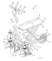
- FIG. 1is an isometric illustration of an exemplary knee walker assembly in accordance with embodiments of the present concepts
- FIG. 2is a partially exploded perspective-view illustration of a portion of the knee walker assembly of FIG. 1 .
- FIG. 3is an enlarged perspective-view illustration of another portion of the knee walker assembly of FIG. 1 .
- FIG. 4is an enlarged perspective-view illustration of an exemplary locking-pin mechanism that may be used with the knee walker assembly of FIG. 1 .
- FIG. 1presents an isometric illustration of an exemplary knee walker assembly, designated generally as 10 , in accordance with various aspects of the present disclosure.
- the drawings presented hereinare not to scale, and are provided purely for explanatory purposes. Thus, the individual and relative dimensions and orientations shown in the drawings are not to be considered limiting.
- the use of spatial adjectives in the specification and claims, such as “front,” “rear,” “forward,” “rearward,” “upward,” “downward,” etc.,are intended, unless explicitly indicated otherwise, to specify the comparative orientation of a given component relative to the knee walker assembly when operatively mounted thereto.
- the knee walker assembly 10is intended for, albeit not per se limited to, aiding a physically impaired person in walking.
- the knee walker assembly 10includes a rigid frame, designated generally at 12 , a support platform 14 that is mounted to the frame 12 , a handle or handle bar 16 , at least one rear wheel 18 mounted to the frame 12 proximate the rear end thereof, and at least two front wheels (e.g., right and left front wheels 20 A and 20 B, respectively) mounted to the frame 12 proximate the front end thereof.
- the frame 12is desirably fabricated from a rigid material, which may include, but is not limited to, metals, such as aluminum and steel, polymers, such as polyvinyl chloride (PVC) and polyethylene terephthalate (PET), glass-fiber composites, etc.
- the frame 12is shown in the drawings comprising a tubular structure with two generally horizontal, longitudinally oriented base beams 22 connected at the front with a laterally oriented cross-beam 24 and at the back with a laterally oriented wheel bearing 26 .
- a front axle 28extends transversely across the front of the frame 12 , rigidly mounted to each of the base beams 22 via a respective upwardly extending coupling bracket 30 (only one of which is visible in the drawings, but a second coupling bracket is also present in the illustrated frame 12 ).
- Optional end plugscan be inserted into the open ends of the base beams 22 , cross-beam 24 , and/or other open tube ends for aesthetic and/or safety purposes.
- the frame 12may comprise fewer or greater than the various beams illustrated in FIG. 1 .
- the length, width, and height of frame 12can be modified, for example, to accommodate the particular user and/or intended application of the knee walker assembly 10 .
- one or more of the beamscan be replaced with alternate structure, such as a base plate or box.
- the base beams 22 and cross-beam 24are exemplified in the drawings as elongated, hollow tubes; alternatively, the beams 22 , 24 may be fabricated as solid bars, and may take on alternative geometries.
- each of the front wheels 20 A, 20 Bis swivel mounted (i.e., attached in a swivel-type mounting configuration) to the front axle 28 .
- swivel mountand “swivel-type mounting configuration” is intended to indicate a mounting arrangement where the wheel can revolve around a rolling axis and rotate about a non-rolling axis.
- each of the front wheels 20 A, 20 Bis connected (e.g., via a wheel-pin or roller bearing) to a respective swivel fork 32 such that the wheel 20 A, 20 B can revolve around its central rolling axis A 1 .
- the swivel fork 32is connected via a swivel joint 34 to the front axle 28 .
- the swivel joint 34allows the swivel fork 32 to rotate about a non-rolling axis A 2 that is laterally offset from the center of the front axle 28 and passes through a diametric plane of the wheel 20 A, 20 B.
- the front wheels 20 A, 20 Bwhen in a swivel-type mounting configuration, can roll around axis A 1 and swivel about axis A 2 , which is generally perpendicular to axis A 1 .
- the swivel mounted wheels 20 A, 20 Bwill tend to automatically align with, and rotate parallel to the direction of travel.
- the rear wheel 18is shown attached in a rigid-type mounting configuration to the rear of the frame 12 .
- “rigid mount” and “rigid-type mounting configuration,” when referring to a wheel,is intended to indicate a mounting arrangement where the wheel can rotate relative to the wheel mount, but the wheel mount cannot rotate relative to the frame.
- the rear wheel 18is rotatably mounted, e.g., via wheel bearing 26 , to the longitudinally oriented base beams 22 such that the wheel 18 can revolve around its central rolling axis A 3 .
- the rear wheel 18cannot swivel on the roller bearing 26 around a non-rolling axis.
- the knee walker assembly 10has a single rear wheel 18 that is longitudinally spaced from and centrally aligned with the front wheels 20 A, 20 B.
- the support platform 14is configured to support at least one human appendage.
- the support platform 14is designed to prop up and hold a user's non-ambulatory lower leg during operation of the knee walker assembly 10 .
- the support platform 14 of FIG. 1includes a cushion 36 fixed to the upper surface of a planar substrate 38 .
- the cushion 36may comprise, for example, a molded plastic body or a foam core that is covered with vinyl or any other suitable material.
- the support platform 14is vertically adjustable (i.e., may be raised or lowered) relative to the frame 12 .
- the support platform 14is mounted on a collapsible stanchion arrangement, designated generally at 40 in FIG. 1 .
- the collapsible stanchion arrangement 40includes a pair of pivoting stanchions 42 that are pivotably attached at respective first ends to the substrate 38 and pivotably attached at respective second ends to the base beams 22 of the frame 12 .
- the collapsible stanchion arrangement 40also includes a pair of sliding stanchions 44 that are pivotably attached at respective first ends to the substrate 38 and pivotably attached at respective second ends to a movable trolley 46 .
- the trolley 46is slidably mounted to the base beams 22 for rectilinear travel between the front and rear ends of the frame 12 .
- the trolley 46is configured to adjust the vertical height of the support platform 14 .
- sliding the trolley 46 forward on the frame 12i.e., to the left in FIG. 1
- the pivoting stanchions 42 and sliding stanchions 44to collapse onto each other in a scissor-like fashion, thereby drawing the support platform 14 down towards the base beams 22 .
- Sliding the trolley 46 in the opposite direction towards the rear end of the frame 12i.e., to the right in FIG.
- the knee walker assembly 10is also provided with a steering mechanism, designated generally as 50 , that is configured to selectively reposition the front wheels 20 A, 20 B such that the knee walker assembly 10 can be maneuvered by the user.
- the steering mechanism 50 shown in FIGS. 1 and 2comprises a steering column 52 that is attached at a first end to the frame 12 and at a second end to the handle bar 16 .
- the steering column 52passes through a hollow sleeve 58 , which is coupled to the front axle 28 and the base beams 22 at the front end of the frame 12 . As best seen in FIG.
- a connector plate 72attaches a T-shaped tie rod 70 to the lower end of the steering column 52 such that the tie rod 70 rotates with the steering column 52 via manipulation of the handle bar 16 .
- Each lateral end 71 , 73 ( FIG. 2 ) of the tie rod 70selectively engages with a respective one of the front wheels 20 A, 20 B, as described below. When so engaged, the tie rod 70 turns the front wheels 20 A, 20 B in response to the rotation of the handle bar 16 and, thus, the steering column 52 .
- the steering column 52may be selectively repositionable between an upright position, exemplified at 52 A in FIG. 2 , and a collapsed position, exemplified schematically with hidden lines at 52 B in FIG. 2 .
- the steering mechanism 50may be provided with a locking hub 54 that is configured to retain the steering column 52 in a plurality of positions relative to the frame 12 , including the upright position 52 A, the collapsed position 52 B, and one or more positions therebetween.
- the steering column 52is separated into two segments, with an upper segment 53 of the steering column 52 fixedly attached to an outer cuff of the locking hub 54 , and a lower segment 55 of the steering column 52 fixedly attached to an inner cuff of the locking hub 54 .
- Rotation of a tension dial 56(e.g., in a counterclockwise direction) will loosen the locking hub 54 , allowing the user to reorient the upper segment 53 of the steering column 52 relative to the lower segment 55 thereof.
- rotation of the tension dial 56 in an opposite directione.g., clockwise
- the handle bar 16includes right and left handle grips 62 A and 62 B, respectively, attached at opposing ends of the upper transverse section of a T-shaped handle mount 60 .
- the handle bar 16may be adjustable, for example, to accommodate users of differing heights and/or for increased compactness during storage of the knee walker assembly 10 .
- the handle mount 60 of FIG. 1is designed to telescope with respect to the steering column 52 .
- the downwardly extending section of the T-shaped handle mount 60is slidably received through an opening in a hollow portion of the upper segment 53 of the steering column 52 .
- a locking screw 64is provided, which is repositionable to allow a user to adjust the position of the handle mount 60 relative to the steering column 52 .
- the locking screw 64e.g., in a counterclockwise direction
- rotation of the locking screw 64in an opposite direction (e.g., clockwise) will mechanically retain the handle mount 60 in the selected orientation.
- Any of a wide variety of alternative coupling mechanismsmay readily be employed as a substitute for the locking screw 64 (e.g., a quick-connect locking device or a spring-biased locking pin).
- alternative handle arrangements, wheels, or other steering configurationsmay be used on alternate embodiments.
- the knee walker assembly 10may be provided with an optional braking mechanism (not shown) that is operable to slow and/or stop the knee walker assembly 10 .
- Both of the front wheels 20 A, 20 B of the knee walker assembly 10are configured to selectively switch between a swivel-type mounting configuration and a rigid-type mounting configuration.
- the knee walker assembly 10 of FIGS. 1-3includes a variable mounting assembly, designated generally as 74 in FIG. 2 , for mounting the front wheels proximate the front end of the frame 12 .
- the variable mounting assembly 74is designed to simultaneously or nearly simultaneously transition both of the front wheels 20 A, 20 B from a swivel-type mounting configuration to a rigid-type mounting configuration, and back.
- the knee walker assembly 10includes a locking mechanism that selectively engages the front wheels 20 A, 20 B to simultaneously or substantially simultaneously lock both of the front wheels 20 A, 20 B in a rigid-type mounting configuration.
- Thisprovides the knee walker assembly 10 with all of the advantages of having swivel-mounted front wheels (e.g., increased maneuverability), while eliminating the disadvantages to a knee walker assembly with only swivel mounted front wheels (e.g., limited control).
- the front wheels 20 A, 20 Bare swivel mounted to the frame 12 by swivel forks 32 and swivel joint 34 .
- a locking disc 76which is most readily visible in FIGS. 2 and 3 , is rigidly fastened to the top of each swivel fork 32 , for example, via a compression bushing 78 and a bushing and nut combination 79 , both of which are part of the swivel joint 34 .
- Each locking disc 76includes an aperture 77 (readily visible in FIG. 2 , but only labeled in FIG. 3 ) that is shaped and sized to receive a locking pin 86 ( FIG. 4 ) to thereby lock the respective front wheel 20 A, 20 B in the rigid-type mounting configuration.
- the knee walker assembly 10also includes a pair of retractable locking pin assemblies 80 , illustrated in FIGS. 3 and 4 , each of which is mounted onto a steering tab 82 at a respective lateral end 71 , 73 of the tie rod 70 .
- Each locking pin assembly 80is configured to selectively engage a respective one of the front wheels 20 A, 20 B—namely, the corresponding locking disc 76 , to thereby lock the front wheel 20 A, 20 B in a rigid-type mounting configuration.
- each retractable locking pin assembly 80comprises a generally hollow, cylindrical housing 84 that is attached (e.g., via fasteners or welding) to one of the steering tabs 82 .
- a locking pin 86is slidably mounted at least partially within the housing 84 .
- a biasing membersuch as a compression spring (not visible in the views provided) is disposed within the housing 84 .
- the biasing memberurges the locking pin 80 into an extended position whereat a distal end of the locking pin 86 extends out of the housing 84 (as seen in FIG. 4 ) into the aperture 77 of the locking disc 76 (as seen in FIG. 3 ).
- each wheel 20 A, 20 Bcan rotate relative to the swivel fork 32 around its respective central rolling axis A 1 , but the fork 32 cannot rotate (i.e., “swivel”) relative to the front axle 28 —i.e., the wheel is in a “rigid-type mounting configuration.”
- a retractor cable 88is routed through a sheath 90 and attached at a proximal end 92 of the locking pin 86 via a cable connector 94 .
- the retractor cable 88is configured to selectively draw the locking pin 86 out of engagement with the locking disc 76 , thereby releasing the front wheels 20 A, 20 B for rotation about the swivel joint 34 .
- an activating lever 98which is shown in FIGS. 1 and 2 , is attached to the handle bar 16 (e.g., at a midsection of the handle mount 60 between the right and left handle grips 62 A and 62 B).
- the activating lever 98is configured to selectively disengage both retractable locking pin assemblies 80 from the locking discs 76 .
- drawing the activating lever 98 backwards(e.g., to the right in FIG. 1 ) will apply a tensile force to the retractor cable 88 , which in turn will transmit the tensile force to the proximal end 92 of the pins 86 via the cable connectors 94 .
- the pins 86will translate longitudinally in a generally rectilinear motion into the housing 84 and out of engagement with the locking discs 76 .
- the swivel joints 34are operable such that the swivel forks 32 can rotate about the non-rolling axes A 2 .
- each wheel 20 A, 20 Bcan rotate relative to the fork 32 around its respective central rolling axis A 1 , and each fork 32 can rotate relative to the front axle 28 around its respective non-rolling axis A 2 —i.e., each wheel is in a “swivel-type mounting configuration.”
- the knee walker assemblycan include a steering locking mechanism that is operable to lock or otherwise secure the steering mechanism 50 in place.
- a steering locking pinthat is operatively mounted, e.g., by a U-shaped mounting bracket, to the frame 12 .
- An actuator cableis attached at one end thereof to the activating lever 98 , and at another end thereof to a proximal end of the steering locking pin.
- both retractable locking pin assemblies 80are disengaged from the locking discs 76 , as described above.
- a distal end of the steering locking pinis engaged with the tie rod 70 —e.g., received via a complementary cavity or hole in a portion of the tie rod 70 , when the lever 98 is activated.
- the steering locking pincan be movably mounted to the U-shaped mounting bracket by a pivot plate. In this instance, the locking pin is attached at a first lateral end of the pivot plate and the actuator cable is attached at an opposing second lateral end of the pivot plate.
- the pivot plateis pivotably mounted to the U-shaped bracket (e.g., via a hinge or pin) to rotate about its center.
- the first lateral end of the pivot platecan be urged upwards by a biasing member (e.g., a compression spring) such that the steering locking pin is biased out of engagement with the tie rod 70 .
- a biasing membere.g., a compression spring
- This tensile forceis applied to the actuator cable, which is transferred to the second lateral end of the pivot plate.
- This tensile forcewill rotate the pivot plate about its central axis, pushing the first lateral end down against the biasing member, thereby feeding the steering locking pin into the hole in the tie rod 70 .
- the tie rod 70is rigidly locked to the frame 12 .
- the steering column 52is thus rigidly locked to the frame 12 via the connector plate 72 that attaches the T-shaped tie rod 70 to the lower end of the steering column 52 .
- the steering mechanism 50cannot be repositioned (or turned) by
- front wheels 20 A, 20 Bwhen the front wheels 20 A, 20 B are released by the retractable locking pin assemblies 80 , they are operable to pivot less than approximately 360 degrees about the non-rolling axis A 2 . In some embodiments, when the front wheels 20 A, 20 B are released by the retractable locking pin assemblies 80 , they are operable to pivot less than approximately 160 degrees about the non-rolling axis A 2 .
- the pivot range of the front wheels 20 A, 20 Bmay be limited by integrating stops or other appropriate structure into the knee walker assembly 10 . Alternatively, when the front wheels 20 A, 20 B are released by the retractable locking pin assemblies 80 , they are operable to freely pivot about the non-rolling axis A 2 .
- an improved method of manufacturing a knee walker assemblyincludes: mounting a support platform to a rigid frame, the support platform being configured to support at least one human appendage; mounting a handle to the frame; mounting at least one rear wheel proximate a rear end of the frame; mounting at least two front wheels proximate a front end of the frame such that the front wheels can transition between a swivel-type mounting configuration and rigid-type mounting configuration; attaching a locking mechanism to the frame, the locking mechanism being configured to substantially simultaneously lock both of the at least two front wheels in the rigid-type mounting configuration.
- the method of manufacturing a knee walker assemblyincludes at least those steps identified in the preceding paragraph. It is also within the scope and spirit of the present invention to omit steps, include additional steps, and/or modify the order presented above.
- the methodalso includes mounting a steering mechanism to the frame, the steering mechanism being configured to selectively reposition the at least two front wheels. It should be further noted that the method represents a single sequence of manufacturing a knee walker assembly. However, it is expected that the method be practiced systematically to manufacture numerous knee walker assemblies. Although the method is described herein with respect to the structure illustrated in FIGS. 1-4 , the claimed methods of the present disclosure are not limited to these exemplary embodiments.
Landscapes
- Engineering & Computer Science (AREA)
- Mechanical Engineering (AREA)
- Chemical & Material Sciences (AREA)
- Combustion & Propulsion (AREA)
- Transportation (AREA)
- Rehabilitation Tools (AREA)
Abstract
Description
Claims (20)
Priority Applications (7)
| Application Number | Priority Date | Filing Date | Title |
|---|---|---|---|
| US12/860,318US8231133B2 (en) | 2010-08-20 | 2010-08-20 | Knee walker |
| CN201180040275.2ACN103068353B (en) | 2010-08-20 | 2011-08-16 | Knee walk helper |
| CA2807173ACA2807173C (en) | 2010-08-20 | 2011-08-16 | Knee walker |
| PCT/US2011/047880WO2012024275A2 (en) | 2010-08-20 | 2011-08-16 | Knee walker |
| US13/413,095US8496257B2 (en) | 2010-08-20 | 2012-03-06 | Knee walker |
| US13/535,700US8827284B2 (en) | 2010-08-20 | 2012-06-28 | Knee walker |
| US13/942,853US8801007B2 (en) | 2010-08-20 | 2013-07-16 | Knee walker |
Applications Claiming Priority (1)
| Application Number | Priority Date | Filing Date | Title |
|---|---|---|---|
| US12/860,318US8231133B2 (en) | 2010-08-20 | 2010-08-20 | Knee walker |
Related Child Applications (1)
| Application Number | Title | Priority Date | Filing Date |
|---|---|---|---|
| US13/413,095DivisionUS8496257B2 (en) | 2010-08-20 | 2012-03-06 | Knee walker |
Publications (2)
| Publication Number | Publication Date |
|---|---|
| US20120043730A1 US20120043730A1 (en) | 2012-02-23 |
| US8231133B2true US8231133B2 (en) | 2012-07-31 |
Family
ID=45593440
Family Applications (3)
| Application Number | Title | Priority Date | Filing Date |
|---|---|---|---|
| US12/860,318Active2030-08-24US8231133B2 (en) | 2010-08-20 | 2010-08-20 | Knee walker |
| US13/413,095ActiveUS8496257B2 (en) | 2010-08-20 | 2012-03-06 | Knee walker |
| US13/942,853ActiveUS8801007B2 (en) | 2010-08-20 | 2013-07-16 | Knee walker |
Family Applications After (2)
| Application Number | Title | Priority Date | Filing Date |
|---|---|---|---|
| US13/413,095ActiveUS8496257B2 (en) | 2010-08-20 | 2012-03-06 | Knee walker |
| US13/942,853ActiveUS8801007B2 (en) | 2010-08-20 | 2013-07-16 | Knee walker |
Country Status (4)
| Country | Link |
|---|---|
| US (3) | US8231133B2 (en) |
| CN (1) | CN103068353B (en) |
| CA (1) | CA2807173C (en) |
| WO (1) | WO2012024275A2 (en) |
Cited By (4)
| Publication number | Priority date | Publication date | Assignee | Title |
|---|---|---|---|---|
| US8523211B2 (en)* | 2011-09-22 | 2013-09-03 | Clinton Allen Mailahn | Knee roller |
| US20150035257A1 (en)* | 2012-02-13 | 2015-02-05 | RoadIX Urban Transportation Ltd. | Urban vehicle |
| US20150076797A1 (en)* | 2012-04-24 | 2015-03-19 | Barbara Elisabeth Alink | Walker device with sitting assembly |
| US9610997B1 (en)* | 2014-06-30 | 2017-04-04 | Walter Edwin Croft | Kneel push cycle apparatus |
Families Citing this family (19)
| Publication number | Priority date | Publication date | Assignee | Title |
|---|---|---|---|---|
| FR2962403B1 (en)* | 2010-07-07 | 2015-03-27 | Raoul Parienti | TRICYCLE ULTRALEGER MOTORIZED ELECTRICALLY |
| US8857832B2 (en)* | 2012-10-04 | 2014-10-14 | Paul Smith | Knee-walker |
| US20140141940A1 (en)* | 2012-11-21 | 2014-05-22 | Ellen Simon | Training Aid for Skaters |
| SE537198C2 (en)* | 2012-11-22 | 2015-03-03 | Kent Edlund | Vehicles with drive device that engage when the driver sits |
| US20170165146A1 (en)* | 2015-12-15 | 2017-06-15 | Justin Franson | Medical knee walker |
| WO2017172473A1 (en)* | 2016-03-31 | 2017-10-05 | University Of Main System Board Of Trustees | Stylized adaptive mobility device |
| DE102016118180B4 (en) | 2016-09-27 | 2018-09-06 | Curvin Gmbh | Modular scooter kit comprising a walker knee roller configurable for at least two medical applications as well as methods for configuring the knee scooter |
| USD810631S1 (en) | 2016-09-27 | 2018-02-20 | Curvin Gmbh | Knee wheeler |
| AU2018224858C1 (en)* | 2017-02-25 | 2021-10-28 | Pride Mobility Products Corporation | Mobility vehicle |
| US10227102B1 (en)* | 2018-09-27 | 2019-03-12 | Ronald Ballou | Mobility assistance vehicle |
| USD891309S1 (en)* | 2019-03-12 | 2020-07-28 | Qingfeng Li | Knee rest walker |
| JP7233398B2 (en) | 2019-06-13 | 2023-03-06 | ワンダーランド スイツァーランド アーゲー | Conveyor with wheels |
| WO2020251728A1 (en)* | 2019-06-14 | 2020-12-17 | Rover Mobility, Llc | Knee walker with four-wheel steering |
| TWI783266B (en)* | 2019-09-11 | 2022-11-11 | 瑞士商明門瑞士股份有限公司 | Child carrier |
| IT202000025645A1 (en)* | 2020-10-29 | 2022-04-29 | Claudio Rosin | WHEELED WALKER |
| CN215153663U (en)* | 2020-12-29 | 2021-12-14 | 明门瑞士股份有限公司 | Wheel orientation structure operated by one hand and child carrier |
| DE102021101944A1 (en)* | 2021-01-28 | 2022-07-28 | Dietz Gmbh | Chassis or rollator with castors |
| DE102021001506B3 (en) | 2021-03-22 | 2022-08-11 | Stefan Anneser | Height-adjustable wheelbarrow |
| US11517493B1 (en) | 2022-02-26 | 2022-12-06 | Priscilla Tang | Motorized convertible knee scooter |
Citations (56)
| Publication number | Priority date | Publication date | Assignee | Title |
|---|---|---|---|---|
| US1288588A (en) | 1918-05-20 | 1918-12-24 | Luther P Holt | Manually-propelled vehicle. |
| US1328343A (en) | 1919-04-18 | 1920-01-20 | Smith Philester | Vehicle |
| US1371421A (en) | 1920-09-14 | 1921-03-15 | Universal Novelty Mfg Company | Coaster-vehicle |
| US1457842A (en) | 1922-02-23 | 1923-06-05 | Walter C Williams | Toy vehicle |
| US1611307A (en) | 1925-03-02 | 1926-12-21 | Harry D Forse | Combination seat and vehicle stand |
| US1668623A (en) | 1925-05-05 | 1928-05-08 | Ralph C Avril | Coaster |
| US2222678A (en) | 1939-07-25 | 1940-11-26 | Samuel S Mittleburg | Scooter board |
| US2530544A (en) | 1949-03-09 | 1950-11-21 | Otto R Schwantes | Walking chair for invalids |
| US2652097A (en) | 1951-04-02 | 1953-09-15 | Eugene R Warren | Rolling crutch |
| US3419283A (en) | 1965-08-17 | 1968-12-31 | Newland David Edward | Folding bicycles |
| US3572757A (en) | 1968-07-09 | 1971-03-30 | Javier Sanglas Camps | Folding frame for a motorcycle |
| US3623749A (en) | 1969-12-29 | 1971-11-30 | Falle R Jensen | Portable bicycle |
| US3990717A (en) | 1975-04-26 | 1976-11-09 | Best Melvin H M | Collapsible vehicle |
| US3992024A (en) | 1975-11-20 | 1976-11-16 | John Workman | Tripodal vehicle |
| US4029329A (en) | 1976-01-19 | 1977-06-14 | Carter Carl Chambers | Child's three-wheel scooter |
| US4065145A (en) | 1976-03-30 | 1977-12-27 | Carter Carl Chambers | Wheeled vehicle for semi-ambulatory medical patients |
| US4202561A (en) | 1977-08-11 | 1980-05-13 | Yonkers Edward H | Collapsible bicycle |
| US4239248A (en) | 1978-10-10 | 1980-12-16 | Ewers Marion H | Collapsible walker |
| US4342466A (en) | 1980-02-08 | 1982-08-03 | Irving Bullet, Jr. | Scooter with seat |
| US4621804A (en) | 1985-03-25 | 1986-11-11 | R-Jayco Ltd. | Therapeutic roller/walker |
| US4750578A (en) | 1987-01-12 | 1988-06-14 | Brandenfels Carl W | Dismantlable and collapsible utility cart |
| US4830133A (en) | 1986-10-01 | 1989-05-16 | Bruno Gaddi | Vehicle with reducible overall dimensions |
| US4844494A (en) | 1988-03-15 | 1989-07-04 | Pierre Blanchard | Collapsible vehicle |
| US4867188A (en) | 1986-01-28 | 1989-09-19 | Michael Reid | Orthopaedic trolley |
| US4907794A (en)* | 1987-12-24 | 1990-03-13 | Guardian Products, Inc. | Foldable rolling walker |
| US4917396A (en) | 1989-03-22 | 1990-04-17 | Sabino Meneses | Tricycle |
| US4930796A (en) | 1988-07-29 | 1990-06-05 | Kransco | Riding vehicle |
| US4944360A (en) | 1988-03-31 | 1990-07-31 | Sturges Daniel D | Platform oriented transportation vehicle |
| US5158313A (en) | 1991-08-12 | 1992-10-27 | Becker Sharon L | Wheeled walker |
| US5167597A (en) | 1991-10-01 | 1992-12-01 | George David | Wheeled walker treatment method |
| US5388659A (en) | 1993-08-19 | 1995-02-14 | Pepe; Anthony | Motorized scooter |
| US5551717A (en) | 1992-04-09 | 1996-09-03 | De Courcey Milne; John | Sports conveyance |
| US5600857A (en) | 1994-11-09 | 1997-02-11 | Heilmann; Steve | Vehicle for carrying a disabled person |
| US5702326A (en) | 1996-05-21 | 1997-12-30 | Versatex Inc. | Walking assistance device |
| US5800317A (en) | 1994-03-14 | 1998-09-01 | Accetta; Roderick William | Four wheel side support kneeling walker |
| US5816593A (en) | 1997-08-11 | 1998-10-06 | Genemax Medical Products Industry Corp. | Walking frame for disabled persons |
| US5839740A (en) | 1997-11-26 | 1998-11-24 | Seeger; Jerral C. | Cart for injured persons |
| US6053189A (en) | 1997-11-19 | 2000-04-25 | Longenecker; Lisa M. | Mobile leg support device |
| US6099002A (en) | 1998-11-05 | 2000-08-08 | Uchie Co., Ltd. | Foldable walking-assistant device |
| US6149170A (en)* | 1998-05-14 | 2000-11-21 | David A. Dotson | Bike-like rehabilitation device |
| US6161860A (en) | 1999-02-11 | 2000-12-19 | Corneau; Michel | Collapsible and convertible walker for disabled persons |
| US6311708B1 (en) | 1999-05-27 | 2001-11-06 | Kaye Products, Inc. | Foldable walker |
| US20010038186A1 (en) | 2000-03-07 | 2001-11-08 | Wychozowycz Barbara Kling | Rolling crutch with braking means |
| US6343802B1 (en)* | 1995-12-14 | 2002-02-05 | Ultimate Support Systems, Inc. | Method and system for concentrated primary support for a user in support assistive devices |
| US20020130482A1 (en) | 2001-03-16 | 2002-09-19 | Jang Jiann Lian | Vehicle movable by rotating handle in a reciprocating action |
| US6481730B2 (en) | 2001-04-20 | 2002-11-19 | Genemax Medical Products Industry Corp. | Walker frame |
| US6520525B1 (en) | 1998-07-21 | 2003-02-18 | Suk Kwon Yoon | Folding tricycle |
| US6634660B2 (en) | 2001-11-21 | 2003-10-21 | Michael S. Miller | Cart for injured person |
| US20040201192A1 (en) | 2003-04-08 | 2004-10-14 | Ramm Sharalyn S. | Kneeling walker systems and methods |
| US20050121873A1 (en) | 2003-06-25 | 2005-06-09 | Miller Michael S. | Cart for injured person |
| US20060033297A1 (en) | 2004-08-12 | 2006-02-16 | Miller Michael L | Collapsible walker for injured person |
| US7001313B1 (en) | 2003-05-23 | 2006-02-21 | Crnkovich Gary M | Exercise assistance device |
| WO2007065174A2 (en) | 2005-12-02 | 2007-06-07 | Rammtlc, Llc | Improved steerable kneeling walker |
| US20070182116A1 (en)* | 2006-01-31 | 2007-08-09 | Enhanced Mobility Systems, Inc. | Mobility scooter |
| US20090058037A1 (en) | 2007-08-31 | 2009-03-05 | Accetta Roderick W | Balance Compensation Apparatus |
| US7780180B2 (en)* | 2007-08-27 | 2010-08-24 | Hoepner John M | Knee walker |
Family Cites Families (2)
| Publication number | Priority date | Publication date | Assignee | Title |
|---|---|---|---|---|
| CH534061A (en)* | 1971-01-20 | 1973-02-28 | Tente Rollen Gmbh & Co | Caster, in particular a swivel castor, with a locking device |
| US5324064A (en)* | 1992-05-01 | 1994-06-28 | Century Products Company | Adjustable height mechanism for a collapsible support frame |
- 2010
- 2010-08-20USUS12/860,318patent/US8231133B2/enactiveActive
- 2011
- 2011-08-16CNCN201180040275.2Apatent/CN103068353B/enactiveActive
- 2011-08-16WOPCT/US2011/047880patent/WO2012024275A2/enactiveApplication Filing
- 2011-08-16CACA2807173Apatent/CA2807173C/enactiveActive
- 2012
- 2012-03-06USUS13/413,095patent/US8496257B2/enactiveActive
- 2013
- 2013-07-16USUS13/942,853patent/US8801007B2/enactiveActive
Patent Citations (57)
| Publication number | Priority date | Publication date | Assignee | Title |
|---|---|---|---|---|
| US1288588A (en) | 1918-05-20 | 1918-12-24 | Luther P Holt | Manually-propelled vehicle. |
| US1328343A (en) | 1919-04-18 | 1920-01-20 | Smith Philester | Vehicle |
| US1371421A (en) | 1920-09-14 | 1921-03-15 | Universal Novelty Mfg Company | Coaster-vehicle |
| US1457842A (en) | 1922-02-23 | 1923-06-05 | Walter C Williams | Toy vehicle |
| US1611307A (en) | 1925-03-02 | 1926-12-21 | Harry D Forse | Combination seat and vehicle stand |
| US1668623A (en) | 1925-05-05 | 1928-05-08 | Ralph C Avril | Coaster |
| US2222678A (en) | 1939-07-25 | 1940-11-26 | Samuel S Mittleburg | Scooter board |
| US2530544A (en) | 1949-03-09 | 1950-11-21 | Otto R Schwantes | Walking chair for invalids |
| US2652097A (en) | 1951-04-02 | 1953-09-15 | Eugene R Warren | Rolling crutch |
| US3419283A (en) | 1965-08-17 | 1968-12-31 | Newland David Edward | Folding bicycles |
| US3572757A (en) | 1968-07-09 | 1971-03-30 | Javier Sanglas Camps | Folding frame for a motorcycle |
| US3623749A (en) | 1969-12-29 | 1971-11-30 | Falle R Jensen | Portable bicycle |
| US3990717A (en) | 1975-04-26 | 1976-11-09 | Best Melvin H M | Collapsible vehicle |
| US3992024A (en) | 1975-11-20 | 1976-11-16 | John Workman | Tripodal vehicle |
| US4029329A (en) | 1976-01-19 | 1977-06-14 | Carter Carl Chambers | Child's three-wheel scooter |
| US4065145A (en) | 1976-03-30 | 1977-12-27 | Carter Carl Chambers | Wheeled vehicle for semi-ambulatory medical patients |
| US4202561A (en) | 1977-08-11 | 1980-05-13 | Yonkers Edward H | Collapsible bicycle |
| US4239248A (en) | 1978-10-10 | 1980-12-16 | Ewers Marion H | Collapsible walker |
| US4342466A (en) | 1980-02-08 | 1982-08-03 | Irving Bullet, Jr. | Scooter with seat |
| US4621804A (en) | 1985-03-25 | 1986-11-11 | R-Jayco Ltd. | Therapeutic roller/walker |
| US4867188A (en) | 1986-01-28 | 1989-09-19 | Michael Reid | Orthopaedic trolley |
| US4830133A (en) | 1986-10-01 | 1989-05-16 | Bruno Gaddi | Vehicle with reducible overall dimensions |
| US4750578A (en) | 1987-01-12 | 1988-06-14 | Brandenfels Carl W | Dismantlable and collapsible utility cart |
| US4907794A (en)* | 1987-12-24 | 1990-03-13 | Guardian Products, Inc. | Foldable rolling walker |
| US4844494A (en) | 1988-03-15 | 1989-07-04 | Pierre Blanchard | Collapsible vehicle |
| US4944360A (en) | 1988-03-31 | 1990-07-31 | Sturges Daniel D | Platform oriented transportation vehicle |
| US4930796A (en) | 1988-07-29 | 1990-06-05 | Kransco | Riding vehicle |
| US4917396A (en) | 1989-03-22 | 1990-04-17 | Sabino Meneses | Tricycle |
| US5158313A (en) | 1991-08-12 | 1992-10-27 | Becker Sharon L | Wheeled walker |
| US5167597A (en) | 1991-10-01 | 1992-12-01 | George David | Wheeled walker treatment method |
| US5551717A (en) | 1992-04-09 | 1996-09-03 | De Courcey Milne; John | Sports conveyance |
| US5388659A (en) | 1993-08-19 | 1995-02-14 | Pepe; Anthony | Motorized scooter |
| US5800317A (en) | 1994-03-14 | 1998-09-01 | Accetta; Roderick William | Four wheel side support kneeling walker |
| US5600857A (en) | 1994-11-09 | 1997-02-11 | Heilmann; Steve | Vehicle for carrying a disabled person |
| US6343802B1 (en)* | 1995-12-14 | 2002-02-05 | Ultimate Support Systems, Inc. | Method and system for concentrated primary support for a user in support assistive devices |
| US5702326A (en) | 1996-05-21 | 1997-12-30 | Versatex Inc. | Walking assistance device |
| US5816593A (en) | 1997-08-11 | 1998-10-06 | Genemax Medical Products Industry Corp. | Walking frame for disabled persons |
| US6053189A (en) | 1997-11-19 | 2000-04-25 | Longenecker; Lisa M. | Mobile leg support device |
| US5839740A (en) | 1997-11-26 | 1998-11-24 | Seeger; Jerral C. | Cart for injured persons |
| US6149170A (en)* | 1998-05-14 | 2000-11-21 | David A. Dotson | Bike-like rehabilitation device |
| US6520525B1 (en) | 1998-07-21 | 2003-02-18 | Suk Kwon Yoon | Folding tricycle |
| US6099002A (en) | 1998-11-05 | 2000-08-08 | Uchie Co., Ltd. | Foldable walking-assistant device |
| US6161860A (en) | 1999-02-11 | 2000-12-19 | Corneau; Michel | Collapsible and convertible walker for disabled persons |
| US6311708B1 (en) | 1999-05-27 | 2001-11-06 | Kaye Products, Inc. | Foldable walker |
| US20010038186A1 (en) | 2000-03-07 | 2001-11-08 | Wychozowycz Barbara Kling | Rolling crutch with braking means |
| US20020130482A1 (en) | 2001-03-16 | 2002-09-19 | Jang Jiann Lian | Vehicle movable by rotating handle in a reciprocating action |
| US6481730B2 (en) | 2001-04-20 | 2002-11-19 | Genemax Medical Products Industry Corp. | Walker frame |
| US6634660B2 (en) | 2001-11-21 | 2003-10-21 | Michael S. Miller | Cart for injured person |
| US6848696B2 (en) | 2001-11-21 | 2005-02-01 | Michael S. Miller | Cart for injured person |
| US20040201192A1 (en) | 2003-04-08 | 2004-10-14 | Ramm Sharalyn S. | Kneeling walker systems and methods |
| US7001313B1 (en) | 2003-05-23 | 2006-02-21 | Crnkovich Gary M | Exercise assistance device |
| US20050121873A1 (en) | 2003-06-25 | 2005-06-09 | Miller Michael S. | Cart for injured person |
| US20060033297A1 (en) | 2004-08-12 | 2006-02-16 | Miller Michael L | Collapsible walker for injured person |
| WO2007065174A2 (en) | 2005-12-02 | 2007-06-07 | Rammtlc, Llc | Improved steerable kneeling walker |
| US20070182116A1 (en)* | 2006-01-31 | 2007-08-09 | Enhanced Mobility Systems, Inc. | Mobility scooter |
| US7780180B2 (en)* | 2007-08-27 | 2010-08-24 | Hoepner John M | Knee walker |
| US20090058037A1 (en) | 2007-08-31 | 2009-03-05 | Accetta Roderick W | Balance Compensation Apparatus |
Non-Patent Citations (3)
| Title |
|---|
| International Search Report mailed Mar. 26, 2012 which issued in corresponding International Patent Application No. PCT/US2011/047880 (5 pages). |
| Medline: Mini 4 Parts List; Issue No. 1 dated Jan. 2005; 15 pages (30-44). |
| Written Opinion mailed Mar. 26, 2012 which issued in corresponding International Patent Application No. PCT/US2011/047880 (6 pages). |
Cited By (6)
| Publication number | Priority date | Publication date | Assignee | Title |
|---|---|---|---|---|
| US8523211B2 (en)* | 2011-09-22 | 2013-09-03 | Clinton Allen Mailahn | Knee roller |
| US20150035257A1 (en)* | 2012-02-13 | 2015-02-05 | RoadIX Urban Transportation Ltd. | Urban vehicle |
| US9272739B2 (en)* | 2012-02-13 | 2016-03-01 | RoadIX Urban Transportation Ltd. | Urban vehicle |
| US20150076797A1 (en)* | 2012-04-24 | 2015-03-19 | Barbara Elisabeth Alink | Walker device with sitting assembly |
| US9623926B2 (en)* | 2012-04-24 | 2017-04-18 | Barbara Elisabeth Alink | Walker device with sitting assembly |
| US9610997B1 (en)* | 2014-06-30 | 2017-04-04 | Walter Edwin Croft | Kneel push cycle apparatus |
Also Published As
| Publication number | Publication date |
|---|---|
| CN103068353A (en) | 2013-04-24 |
| US8801007B2 (en) | 2014-08-12 |
| US20120043730A1 (en) | 2012-02-23 |
| WO2012024275A2 (en) | 2012-02-23 |
| CA2807173A1 (en) | 2012-02-23 |
| US8496257B2 (en) | 2013-07-30 |
| US20120161416A1 (en) | 2012-06-28 |
| WO2012024275A3 (en) | 2012-05-18 |
| CN103068353B (en) | 2016-05-18 |
| CA2807173C (en) | 2016-12-13 |
| US20130300080A1 (en) | 2013-11-14 |
Similar Documents
| Publication | Publication Date | Title |
|---|---|---|
| US8231133B2 (en) | Knee walker | |
| US8827284B2 (en) | Knee walker | |
| CA2820031C (en) | Knee walker | |
| US6338493B1 (en) | Walker chair | |
| US10717491B1 (en) | Folding scooter | |
| US8348288B1 (en) | Knee scooter | |
| US20060033297A1 (en) | Collapsible walker for injured person | |
| US6991243B2 (en) | Platform scooter for larger children and handicapped persons | |
| US20070182116A1 (en) | Mobility scooter | |
| US20090194142A1 (en) | Two-Wheeled In-Line Walker | |
| CN104349765A (en) | Walker device with seating assembly | |
| US20070216122A1 (en) | Mobility Cart | |
| US20100012400A1 (en) | Wheelchair having torsion-acting shock absorption and detachable dirve train | |
| US11052001B2 (en) | Mobile chair apparatus comprising foot pedals | |
| US9757289B1 (en) | Mobile chair apparatus comprising foot pedals | |
| WO2022224238A1 (en) | Scooter convertible to push-cart | |
| US10076456B2 (en) | Mobile chair apparatus comprising foot pedals | |
| US9757288B1 (en) | Mobile chair apparatus comprising foot pedals | |
| US20240092448A1 (en) | Scooter convertible to push-cart | |
| US11370504B2 (en) | Mobility scooter with folding feature and related methods | |
| WO2021061696A1 (en) | Folding scooter | |
| HK40013897B (en) | Mobile chair apparatus comprising foot pedals | |
| HK40013897A (en) | Mobile chair apparatus comprising foot pedals |
Legal Events
| Date | Code | Title | Description |
|---|---|---|---|
| AS | Assignment | Owner name:MEDLINE INDUSTRIES, INC., ILLINOIS Free format text:ASSIGNMENT OF ASSIGNORS INTEREST;ASSIGNORS:WALTHER, LINDA M.;ABERNATHEY, ETHAN S.;KUTSCH, JOHN H.;AND OTHERS;SIGNING DATES FROM 20100820 TO 20100826;REEL/FRAME:025166/0856 | |
| STCF | Information on status: patent grant | Free format text:PATENTED CASE | |
| CC | Certificate of correction | ||
| FPAY | Fee payment | Year of fee payment:4 | |
| MAFP | Maintenance fee payment | Free format text:PAYMENT OF MAINTENANCE FEE, 8TH YEAR, LARGE ENTITY (ORIGINAL EVENT CODE: M1552); ENTITY STATUS OF PATENT OWNER: LARGE ENTITY Year of fee payment:8 | |
| AS | Assignment | Owner name:BANK OF AMERICA, N.A., TEXAS Free format text:SECURITY INTEREST;ASSIGNOR:MEDLINE INDUSTRIES, LP;REEL/FRAME:058040/0001 Effective date:20211021 Owner name:WILMINGTON TRUST, NATIONAL ASSOCIATION, MINNESOTA Free format text:SECURITY INTEREST;ASSIGNOR:MEDLINE INDUSTRIES, LP;REEL/FRAME:057927/0091 Effective date:20211021 | |
| MAFP | Maintenance fee payment | Free format text:PAYMENT OF MAINTENANCE FEE, 12TH YEAR, LARGE ENTITY (ORIGINAL EVENT CODE: M1553); ENTITY STATUS OF PATENT OWNER: LARGE ENTITY Year of fee payment:12 | |
| AS | Assignment | Owner name:WILMINGTON TRUST, NATIONAL ASSOCIATION, AS NOTES COLLATERAL AGENT, MINNESOTA Free format text:PATENT SECURITY AGREEMENT;ASSIGNOR:MEDLINE INDUSTRIES, LP;REEL/FRAME:071672/0100 Effective date:20240327 |